WO2014092096A1 - 車両用計器装置 - Google Patents
車両用計器装置 Download PDFInfo
- Publication number
- WO2014092096A1 WO2014092096A1 PCT/JP2013/083125 JP2013083125W WO2014092096A1 WO 2014092096 A1 WO2014092096 A1 WO 2014092096A1 JP 2013083125 W JP2013083125 W JP 2013083125W WO 2014092096 A1 WO2014092096 A1 WO 2014092096A1
- Authority
- WO
- WIPO (PCT)
- Prior art keywords
- display unit
- circuit board
- control circuit
- liquid crystal
- crystal display
- Prior art date
- Legal status (The legal status is an assumption and is not a legal conclusion. Google has not performed a legal analysis and makes no representation as to the accuracy of the status listed.)
- Ceased
Links
Images


Classifications
-
- B—PERFORMING OPERATIONS; TRANSPORTING
- B60—VEHICLES IN GENERAL
- B60K—ARRANGEMENT OR MOUNTING OF PROPULSION UNITS OR OF TRANSMISSIONS IN VEHICLES; ARRANGEMENT OR MOUNTING OF PLURAL DIVERSE PRIME-MOVERS IN VEHICLES; AUXILIARY DRIVES FOR VEHICLES; INSTRUMENTATION OR DASHBOARDS FOR VEHICLES; ARRANGEMENTS IN CONNECTION WITH COOLING, AIR INTAKE, GAS EXHAUST OR FUEL SUPPLY OF PROPULSION UNITS IN VEHICLES
- B60K35/00—Instruments specially adapted for vehicles; Arrangement of instruments in or on vehicles
- B60K35/20—Output arrangements, i.e. from vehicle to user, associated with vehicle functions or specially adapted therefor
- B60K35/21—Output arrangements, i.e. from vehicle to user, associated with vehicle functions or specially adapted therefor using visual output, e.g. blinking lights or matrix displays
- B60K35/215—Output arrangements, i.e. from vehicle to user, associated with vehicle functions or specially adapted therefor using visual output, e.g. blinking lights or matrix displays characterised by the combination of multiple visual outputs, e.g. combined instruments with analogue meters and additional displays
-
- B—PERFORMING OPERATIONS; TRANSPORTING
- B60—VEHICLES IN GENERAL
- B60K—ARRANGEMENT OR MOUNTING OF PROPULSION UNITS OR OF TRANSMISSIONS IN VEHICLES; ARRANGEMENT OR MOUNTING OF PLURAL DIVERSE PRIME-MOVERS IN VEHICLES; AUXILIARY DRIVES FOR VEHICLES; INSTRUMENTATION OR DASHBOARDS FOR VEHICLES; ARRANGEMENTS IN CONNECTION WITH COOLING, AIR INTAKE, GAS EXHAUST OR FUEL SUPPLY OF PROPULSION UNITS IN VEHICLES
- B60K35/00—Instruments specially adapted for vehicles; Arrangement of instruments in or on vehicles
- B60K35/80—Arrangements for controlling instruments
- B60K35/81—Arrangements for controlling instruments for controlling displays
Definitions
- the present invention relates to a vehicle instrument device in which a pointer-type instrument and a display unit are arranged in parallel.
- FIG. 3 shows a vehicle instrument device disclosed in Patent Document 1 below.
- the vehicle instrument device 100 is a composite meter (combination meter) disposed on a dashboard of a vehicle.
- a pointer-type meter (not shown) such as a speedometer and a tachometer, and a liquid crystal
- the display unit (display unit) 120 is arranged in parallel.
- a display accommodation space 111 is secured at the center of the apparatus housing 110.
- the display housing space 111 is a space in which the liquid crystal display unit 120 is incorporated.
- the liquid crystal display unit 120 can operate with multiple functions, and can function as, for example, an odometer that indicates a travel distance, a fuel consumption meter, a gear position indicator, and the like.
- the apparatus housing 110 shown in FIG. 3 is provided with a speedometer placement section 112 in which a speedometer as a pointer-type instrument is placed and a tachometer placement section 113 in which a tachometer as a pointer-type instrument is placed. Yes.
- the vehicle instrument device 100 shown in FIG. 3 is designed such that pointer-type instruments are arranged on both sides of the liquid crystal display unit 120, respectively.
- the electronic circuit for controlling the operation of the liquid crystal display unit and the electronic circuit for controlling the operation of the pointer-type instrument are both formed on a common circuit board. Often.
- the display unit when the electronic circuit for controlling the operation of the display unit and the electronic circuit for controlling the operation of the pointer-type meter are formed on a common circuit board, the display unit From the viewpoint of satisfying the requirements for electronic circuits, a multilayer substrate having four or more layers is used as the circuit substrate. Therefore, the circuit board becomes an excessive quality with respect to the electronic circuit for the pointer-type instrument, which causes an increase in the cost of the vehicle instrument device.
- an object of the present invention is to solve the above-mentioned problems, and in a vehicle instrument device in which a pointer-type instrument and a display unit are provided in parallel, a pointer control circuit board for controlling the operation of the pointer-type instrument Is to provide an instrument device for a vehicle that can reduce the cost by preventing excessive quality.
- a vehicle instrument device in which a pointer-type instrument and a display unit are juxtaposed,
- the display control circuit board for controlling the operation of the display unit is separate from the pointer control circuit board for controlling the operation of the pointer-type instrument, and the front view dimension is the front view dimension of the display unit.
- the display instrument is a vehicle instrument device arranged in parallel with the pointer-type instrument as a display unit integrated with the display control circuit board.
- the display control circuit board is a vehicular instrument device in which an external connection connector for connecting to an external circuit is provided on an outer surface located on the opposite side of the display unit.
- the display unit is a liquid crystal display unit
- An instrument device for a vehicle wherein the display control circuit board is an LCD control circuit board.
- the display control circuit board for controlling the operation of the display unit is separate from the pointer control circuit board for controlling the operation of the pointer-type instrument. Therefore, even when a circuit board as a display control circuit board uses a multilayer board of four or more layers, which is advantageous for realizing high-density mounting while ensuring reliability against noise resistance, noise resistance and For example, an inexpensive circuit board having three or less layers can be used as a circuit board as a pointer control circuit board that is not required to be mounted as easily as a display control circuit board.
- the display unit is arranged in parallel with the pointer-type instrument as a display unit integrated with the display control circuit board, so that the pointer for controlling the operation of the pointer-type instrument is provided.
- the control circuit board can be designed independently as a simple circuit board that does not include a circuit for controlling the operation of the display unit, and the design of the pointer control circuit board can be facilitated. In addition, it is easy to share the display unit.
- the outer surface of the display control circuit board equipped with the external connector is a surface located on the side opposite to the display unit and exposed to the outside. Therefore, the external connection connector is provided in a state exposed to the outside, and can be easily connected to an external circuit.
- both the signal cable for sending a signal necessary for the operation of the display unit and the power cable for supplying power are connected to the external connection connector on the outer surface of the display control circuit board. Therefore, connection work of each cable can be facilitated.
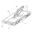
- FIG. 1 is a perspective view of a display unit in an embodiment of a vehicle instrument device according to the present invention.
- FIG. 2 is a development view of the display unit shown in FIG.
- FIG. 3 is a perspective view of a conventional vehicle instrument device.
- FIG. 1 is a perspective view of a display unit in an embodiment of a vehicle instrument device according to the present invention
- FIG. 2 is a development view of the display unit shown in FIG.
- the vehicle instrument device 1 is a combination meter disposed on a dashboard of a vehicle.
- a pointer-type meter 50 and a liquid crystal display unit (display unit) 10 are provided on a device housing (not shown). It is installed side by side.
- Examples of the pointer-type meter 50 include a speedometer and a tachometer.
- an LCD control circuit board (display control circuit board) 20 is detachably attached to the back surface of the liquid crystal display unit 10 which is a display unit.
- the LCD control circuit board 20 is a board for controlling the operation of the liquid crystal display unit 10, and is formed separately from the pointer control circuit board 60 for controlling the operation of the pointer-type instrument 50.
- the liquid crystal display unit 10 is juxtaposed with the pointer-type meter 50 as a liquid crystal display unit (display unit) 30 integrated with the LCD control circuit board 20.
- the liquid crystal display unit 10 covers a liquid crystal display panel 11 having a display surface 11 a for displaying an image, a box-shaped LCD case 15 covering the back side and the outer periphery of the liquid crystal display panel 11, and the back side of the LCD case 15.
- a metal bottom plate 16 and a metal bezel 18 that covers the periphery of the liquid crystal display panel 11 are provided.
- the box-type LCD case 15 is made of resin.
- the LCD case 15 includes a bottom wall portion 15a (see FIG. 2) that covers the back surface of the liquid crystal display panel 11 from the outside of the backlight, and a side wall portion 15b (see FIG. 1) that covers the outer periphery of the liquid crystal display panel 11. ing.
- the bottom plate 16 covers the bottom wall portion 15a of the LCD case 15 as shown in FIG.
- the bottom wall 15a of the LCD case 15 is provided with two mounting holes 151 for mounting the LCD control circuit board 20, two positioning pins 152, and two locking claws 153.
- the mounting hole 151, the positioning pin 152, and the locking claw 153 are all exposed outward from the notch 161 formed in the bottom plate 16.
- the two mounting holes 151 are holes for screwing the LCD control circuit board 20 and are formed with female screws.
- the two attachment holes 151 are provided at one diagonal on the rectangular bottom surface of the LCD case 15.
- the two positioning pins 152 have a structure in which a thin pin body 152b protrudes from the center of the large diameter boss portion 152a, and is provided at the other diagonal of the rectangular bottom surface of the LCD case 15. Each positioning pin 152 positions the LCD control circuit board 20 by inserting the pin main body 152b into a positioning hole 252 formed through the LCD control circuit board 20.
- the two locking claws 153 are engaged with the edge of the LCD control circuit board 20 when the LCD control circuit board 20 is positioned on the back surface of the liquid crystal display unit 10 by the two positioning pins 152, and the LCD control The circuit board 20 is temporarily fixed.
- an FPC (Flexible Printed Circuit) 19 for electrically connecting the liquid crystal display unit 10 and the LCD control circuit board 20 is drawn out.
- the FPC 19 is led out from the liquid crystal display unit 10, and the tip 19 a is connected to the LCD control circuit board 20 by the FPC connector 42.
- the part 191 laid on the bottom plate 16 of the FPC 19 is fixed in a state of surface contact with the bottom plate 16 by the adhesive mounting tape 170 and the pressing claws 157.
- an electronic component 192 is mounted on a portion 191 laid on the bottom plate 16 of the FPC 19.
- the tip 19a of the FPC 19 protrudes to the outside of the bottom plate 16, and as shown in FIG. 2, is connected to the FPC connector 42 on the LCD control circuit board 20 arranged in a plane adjacent to the liquid crystal display unit 10. Is done.
- the portion 193 of the FPC 19 that protrudes outside the bottom plate 16 is laid on the bottom plate 16 of the FPC 19 at the position of the broken line L1 in FIG. 2 when the LCD control circuit board 20 is attached to the back surface of the liquid crystal display unit 10. It is folded on the part 191 to be turned. That is, the portion 193 of the FPC 19 that protrudes outside the bottom plate 16 is folded between the portion 191 laid on the bottom plate 16 of the FPC 19 and accommodated between the liquid crystal display unit 10 and the LCD control circuit board 20. .
- the bezel 18 is a press-molded product made of a metal plate. As shown in FIG. 1, the front edge frame portion 181 that borders the display surface 11 a of the liquid crystal display panel 11 and the outside of the side wall portion 15 b of the LCD case 15. And an outer peripheral frame portion 182 that covers the outer periphery.
- an FPC cover portion 182 a is provided at a position facing the folded portion 19 b of the FPC 19 in the outer peripheral frame portion 182 of the bezel 18.
- the FPC cover 182a is formed longer in the thickness direction of the liquid crystal display unit 10 (the arrow X1 side in FIG. 1) than the surrounding outer peripheral frame 182 so as to cover the outside of the folded portion 19b of the FPC 19. .
- the LCD control circuit board 20 includes various electronic components 41a, 41b, 41c, 41d, and 41e for controlling the operation of the liquid crystal display unit 10, as shown in FIG.
- An FPC connector 42 and an external connection connector 43 are mounted.
- the LCD control circuit board 20 has a front view dimension set substantially the same as the front view dimension of the liquid crystal display unit 10. That is, in FIG. 2, the width dimension W1 of the liquid crystal display unit 10 and the width dimension W2 of the LCD control circuit board 20 are set to be approximately equal. In FIG. 2, the length dimension H1 of the liquid crystal display unit 10 and the length dimension H2 of the LCD control circuit board 20 are set to be approximately equal.
- the electronic component 41 a is a CPU (Central Processing Unit) and is located on the opposite side of the liquid crystal display unit 10. 21 is mounted on the outer surface 21a.
- the electronic component 41b is an LCD (Liquid Crystal Display) driver, and is mounted on the inner surface 21b of the multilayer substrate 21 located on the liquid crystal display unit 10 side.
- the FPC connector 42 mounted on the multilayer substrate 21 is a connector to which the tip 19a of the FPC 19 led to the back surface of the liquid crystal display unit 10 is connected.
- the FPC connector 42 is mounted on the inner surface 21 b of the multilayer substrate 21.
- the LCD control circuit board 20 is assembled to the back surface of the liquid crystal display unit 10 so that the inner surface 21b of the multilayer substrate 21 faces the back surface of the liquid crystal display unit 10.
- a regulation rib 158 protrudes at a position facing the FPC connector 42 on the LCD control circuit board 20.
- the restriction rib 158 is integrally formed with the bottom wall portion 15 a of the LCD case 15.
- the restriction rib 158 interferes with the FPC connector 42 when the LCD control circuit board 20 is assembled to the back surface of the liquid crystal display unit 10.
- the assembly of the LCD control circuit board 20 is disabled and a connection failure is detected.
- the external connection connector 43 mounted on the multilayer substrate 21 is a connector for connecting to an external circuit.
- the external connection connector 43 is mounted on the outer surface 21 a of the multilayer substrate 21.
- the external connection connector 43 is connected with a signal cable 71 for sending a signal necessary for the operation of the liquid crystal display unit 30, a power supply cable 73 for supplying power, and a GND cable 75 as external circuits.
- the multi-layer substrate 21 is provided with two mounting holes 251, two positioning holes 252, and two locking notches 253 for fixing to the back surface of the liquid crystal display unit 10.
- the two mounting holes 251 are holes corresponding to the mounting holes 151 on the back surface of the liquid crystal display unit 10 and are holes through which male screws that are screwed into the mounting holes 151 can be inserted.
- the two positioning holes 252 are holes corresponding to the positioning pins 152 on the back surface of the liquid crystal display unit 10.
- the two positioning holes 252 are positioned by inserting the pin main body 152b of the positioning pin 152.
- the two locking notches 253 are portions where the locking claws 153 on the back surface of the liquid crystal display unit 10 are engaged.
- a ground terminal 61 is provided on the inner surface 21 b of the multilayer substrate 21.
- the ground terminal 61 is made of metal and has a base end soldered on a grounding pattern (GND pattern) on the multilayer substrate 21.
- the ground terminal 61 has an LCD ground portion that elastically contacts the bottom plate 16 of the metal bezel 18 when the LCD control circuit board 20 is assembled to the liquid crystal display unit 10.
- the casing contact portion elastically contacts the bottom plate 16, and the bottom plate 16 and the GND pattern 23 are in a conductive state.
- the GND pattern on the multilayer substrate 21 to which the ground terminal 61 is soldered is connected to an external GND cable via the external connection connector 43.
- the GND pattern is provided at a position close to the external connection connector 43.
- the back surface of the liquid crystal display unit 10 and the LCD control circuit board 20 are arranged in a plane, and the tip 19a of the FPC 19 is an FPC connector on the inner surface 21b of the LCD control circuit board 20. 42.
- the FPC 19 is folded back at the position of the broken line L 1 in FIG. 2, and the inner surface 21 b of the LCD control circuit board 20 is overlaid on the back surface of the liquid crystal display unit 10.
- the positioning pins 152 of the liquid crystal display unit 10 and the positioning holes 252 of the LCD control circuit board 20 are aligned, so that the locking claws 153 of the liquid crystal display unit 10 are moved to the LCD as shown in FIG.
- the LCD control circuit board 20 is temporarily fixed to the back surface of the liquid crystal display unit 10 by being engaged with the locking notch 253 of the control circuit board 20.
- the male screw inserted into the mounting hole 251 of the LCD control circuit board 20 is screwed into the mounting hole 151 of the liquid crystal display unit 10, whereby the LCD control circuit board 20 is fixed to the back surface of the liquid crystal display unit 10, and the liquid crystal Assembling is completed as the display unit 30.
- the liquid crystal display unit 30 described above can function as, for example, an odometer indicating a travel distance, a fuel consumption meter, a gear position indicator, and the like.
- the LCD control circuit board 20 for controlling the operation of the liquid crystal display unit 10 is the pointer control circuit board for controlling the operation of the pointer-type instrument 50.
- 60 is a separate body. Therefore, even when a circuit board as the LCD control circuit board 20 uses a multilayer board having four or more layers, which is advantageous in achieving high-density mounting while ensuring reliability against noise resistance, the noise resistance is high.
- an inexpensive circuit board having three or less layers can be used as the circuit board as the pointer control circuit board 60 that is not required to be as good as the LCD control circuit board 20.
- the liquid crystal display unit 10 is juxtaposed with the pointer-type instrument 50 as the liquid crystal display unit 30 integrated with the LCD control circuit board 20.
- the pointer control circuit board 60 for controlling the operation of the pointer can be designed independently as a simple circuit board that does not include a circuit for controlling the operation of the liquid crystal display unit 10. Design can be made easy. Further, it is easy to share the liquid crystal display unit 10.
- the liquid crystal display unit 30 can be set to the minimum front view size. Assembling property (space property) can be made advantageous, and the maximum electronic component mounting area can be secured within the dimensions.
- the outer surface of the LCD control circuit board 20 provided with the external connection connector 43 (the outer surface 21 a of the multilayer board 21) is opposite to the liquid crystal display unit 10. It is a surface which is located on the outside and is exposed to the outside. Therefore, the external connection connector 43 is provided in a state exposed to the outside, and can be easily connected to an external circuit.
- the signal cable 71 for sending a signal necessary for the operation of the liquid crystal display unit 30 and the power supply cable 73 for supplying power are both outside the LCD control circuit board 20. It is connected to the external connection connector 43 on the surface. Therefore, the connection work of each cable can be facilitated.
- this invention is not limited to embodiment mentioned above, A deformation
- the material, shape, dimensions, number, arrangement location, and the like of each component in the above-described embodiment are arbitrary and are not limited as long as the present invention can be achieved.
- the liquid crystal display unit 10 and the LCD control circuit board 20 have been described as examples.
- other display units such as an organic EL display unit and an organic EL display control circuit board, and a display control circuit board. Of course, can be used.
- a vehicle instrument device (1) in which a pointer-type instrument (50) and a display unit (liquid crystal display unit 10) are provided in parallel,
- a display control circuit board (LCD control circuit board 20) for controlling the operation of the display unit (liquid crystal display unit 10) is a pointer control circuit board (60) for controlling the operation of the pointer-type instrument (50).
- a front view dimension is set to be substantially the same as the front view dimension of the liquid crystal display unit (liquid crystal display unit 10), and is assembled to the back surface of the liquid crystal display unit (liquid crystal display unit 10).
- the liquid crystal display unit (liquid crystal display unit 10) is arranged in parallel with the pointer-type instrument (50) as a display unit (liquid crystal display unit 30) integrated with the display control circuit board (LCD control circuit board 20).
- Vehicle instrument device (1) in which a pointer-type instrument (50) and a display unit (liquid crystal display unit 10) are provided in parallel
- the control circuit board (LCD control circuit board 20) includes an external connection connector (43) for connecting to an external circuit on an outer surface located on the opposite side of the display unit (liquid crystal display unit 10).
- the control circuit board includes an external connection connector (43) for connecting to an external circuit on an outer surface located on the opposite side of the display unit (liquid crystal display unit 10).
- the vehicle instrument device (1) Connected to the external connector (43) are a signal cable (71) for sending a signal necessary for the operation of the display unit (liquid crystal display unit 30) and a power cable (73) for supplying power as the external circuit. Vehicle instrument device (1).
- the display unit is a liquid crystal display unit (10), The vehicle instrument device (1), wherein the display control circuit board is an LCD control circuit board (20).
- the pointer control circuit board for controlling the operation of the pointer-type instrument becomes excessive quality. Can be prevented and the cost can be reduced.
- liquid crystal display unit (display unit) 20 LCD control circuit board (display control circuit board) 30 Liquid crystal display unit (display unit) 43 External connection connector 50 Pointer type instrument 60 Pointer control circuit board 71 Signal cable 73 Power cable
Landscapes
- Engineering & Computer Science (AREA)
- Chemical & Material Sciences (AREA)
- Combustion & Propulsion (AREA)
- Transportation (AREA)
- Mechanical Engineering (AREA)
- Instrument Panels (AREA)
- Liquid Crystal (AREA)
- Devices For Indicating Variable Information By Combining Individual Elements (AREA)
Priority Applications (3)
| Application Number | Priority Date | Filing Date | Title |
|---|---|---|---|
| DE112013005885.5T DE112013005885B4 (de) | 2012-12-10 | 2013-12-10 | Instrumentenvorrichtung für Fahrzeuge |
| CN201380064582.3A CN104838239A (zh) | 2012-12-10 | 2013-12-10 | 车辆仪器装置 |
| US14/734,776 US9969264B2 (en) | 2012-12-10 | 2015-06-09 | Vehicle instrument device |
Applications Claiming Priority (2)
| Application Number | Priority Date | Filing Date | Title |
|---|---|---|---|
| JP2012269629A JP6023575B2 (ja) | 2012-12-10 | 2012-12-10 | 車両用計器装置 |
| JP2012-269629 | 2012-12-10 |
Related Child Applications (1)
| Application Number | Title | Priority Date | Filing Date |
|---|---|---|---|
| US14/734,776 Continuation US9969264B2 (en) | 2012-12-10 | 2015-06-09 | Vehicle instrument device |
Publications (1)
| Publication Number | Publication Date |
|---|---|
| WO2014092096A1 true WO2014092096A1 (ja) | 2014-06-19 |
Family
ID=50934384
Family Applications (1)
| Application Number | Title | Priority Date | Filing Date |
|---|---|---|---|
| PCT/JP2013/083125 Ceased WO2014092096A1 (ja) | 2012-12-10 | 2013-12-10 | 車両用計器装置 |
Country Status (5)
| Country | Link |
|---|---|
| US (1) | US9969264B2 (https=) |
| JP (1) | JP6023575B2 (https=) |
| CN (1) | CN104838239A (https=) |
| DE (1) | DE112013005885B4 (https=) |
| WO (1) | WO2014092096A1 (https=) |
Families Citing this family (6)
| Publication number | Priority date | Publication date | Assignee | Title |
|---|---|---|---|---|
| KR101651787B1 (ko) * | 2015-07-03 | 2016-08-26 | 덴소코리아일렉트로닉스 주식회사 | 차량용 클러스터 시스템 |
| KR101651788B1 (ko) * | 2015-07-03 | 2016-08-29 | 덴소코리아일렉트로닉스 주식회사 | 차량용 클러스터 시스템 |
| KR101651785B1 (ko) * | 2015-07-03 | 2016-08-26 | 덴소코리아일렉트로닉스 주식회사 | 차량용 클러스터 시스템 |
| KR101651786B1 (ko) * | 2015-07-03 | 2016-08-29 | 덴소코리아일렉트로닉스 주식회사 | 차량용 클러스터 시스템 |
| KR20210080111A (ko) * | 2019-12-20 | 2021-06-30 | 현대모비스 주식회사 | 조립 구조를 강화한 차량용 헤드업 디스플레이 장치 |
| CN113320386B (zh) * | 2021-06-08 | 2023-08-04 | 浙江汽车仪表有限公司 | 一种低温稳定性好且可靠性高的汽车全液晶仪表盘 |
Citations (2)
| Publication number | Priority date | Publication date | Assignee | Title |
|---|---|---|---|---|
| JP2008026117A (ja) * | 2006-07-20 | 2008-02-07 | Nippon Seiki Co Ltd | 車両用計器 |
| JP2011095117A (ja) * | 2009-10-30 | 2011-05-12 | Nippon Seiki Co Ltd | 表示装置 |
Family Cites Families (9)
| Publication number | Priority date | Publication date | Assignee | Title |
|---|---|---|---|---|
| JPH11118529A (ja) * | 1997-10-21 | 1999-04-30 | Nippon Seiki Co Ltd | 計器装置 |
| DE102005042863A1 (de) * | 2005-09-08 | 2007-03-22 | Ford-Werke Gmbh | Fahrerinformationssystem in einem Kraftfahrzeug |
| JP5034961B2 (ja) * | 2008-01-11 | 2012-09-26 | 株式会社デンソー | 指針計器 |
| CN101318473A (zh) * | 2008-05-22 | 2008-12-10 | 中国科学院电工研究所 | 一种混合动力车综合仪表系统 |
| CN201320967Y (zh) * | 2008-12-27 | 2009-10-07 | 东风襄樊仪表系统有限公司 | 多功能集成信息显示组合仪表 |
| CN201354012Y (zh) * | 2008-12-30 | 2009-12-02 | 吉林大学 | 汽车总线数字组合仪表 |
| JP2010181478A (ja) * | 2009-02-03 | 2010-08-19 | Yazaki Corp | 表示装置の取付構造 |
| WO2012050573A1 (en) * | 2010-10-13 | 2012-04-19 | Hewlett-Packard Development Company, L.P. | Dashboard display method and apparatus |
| CN202110419U (zh) * | 2011-01-21 | 2012-01-11 | 广东好帮手电子科技股份有限公司 | 基于汽车总线的全数字智能仪表系统 |
-
2012
- 2012-12-10 JP JP2012269629A patent/JP6023575B2/ja active Active
-
2013
- 2013-12-10 WO PCT/JP2013/083125 patent/WO2014092096A1/ja not_active Ceased
- 2013-12-10 DE DE112013005885.5T patent/DE112013005885B4/de active Active
- 2013-12-10 CN CN201380064582.3A patent/CN104838239A/zh active Pending
-
2015
- 2015-06-09 US US14/734,776 patent/US9969264B2/en active Active
Patent Citations (2)
| Publication number | Priority date | Publication date | Assignee | Title |
|---|---|---|---|---|
| JP2008026117A (ja) * | 2006-07-20 | 2008-02-07 | Nippon Seiki Co Ltd | 車両用計器 |
| JP2011095117A (ja) * | 2009-10-30 | 2011-05-12 | Nippon Seiki Co Ltd | 表示装置 |
Also Published As
| Publication number | Publication date |
|---|---|
| CN104838239A (zh) | 2015-08-12 |
| DE112013005885B4 (de) | 2025-11-13 |
| JP6023575B2 (ja) | 2016-11-09 |
| US9969264B2 (en) | 2018-05-15 |
| JP2014115192A (ja) | 2014-06-26 |
| US20150266380A1 (en) | 2015-09-24 |
| DE112013005885T5 (de) | 2015-09-10 |
Similar Documents
| Publication | Publication Date | Title |
|---|---|---|
| JP6023575B2 (ja) | 車両用計器装置 | |
| US10388198B2 (en) | Vehicular display device | |
| US5652508A (en) | Odometer assembly incorporating electronic drive of speedometer and tachometer | |
| CA2954343C (en) | Display unit for vehicle and display control unit | |
| JP5304217B2 (ja) | 電子装置 | |
| JP6077847B2 (ja) | 液晶表示ユニット | |
| JP5288257B2 (ja) | 表示装置 | |
| JP5510391B2 (ja) | 電気回路装置 | |
| JP6198553B2 (ja) | 表示装置 | |
| US11752868B2 (en) | Instrument device for a vehicle | |
| JP5382339B2 (ja) | 表示装置 | |
| JP6077848B2 (ja) | 液晶表示ユニット | |
| JP5966126B2 (ja) | 車載機器接続用アダプタ | |
| JP6440133B2 (ja) | 車載機器接続用アダプタ | |
| JP2015221663A (ja) | 車載機器接続用アダプタ | |
| JP5189268B2 (ja) | 車両用表示装置 | |
| JP2010052714A (ja) | 車両用表示装置 | |
| JP6452867B2 (ja) | 車載機器接続用アダプタ | |
| JP3098167B2 (ja) | ユニットの照明構造 | |
| JP6597463B2 (ja) | 車両用計器 | |
| JP6482010B2 (ja) | 車載機器接続用アダプタ | |
| JP2528821Y2 (ja) | メータケースの配線接続構造 | |
| JP2016118641A (ja) | 表示装置 | |
| JPH09134136A (ja) | 車両用表示装置 |
Legal Events
| Date | Code | Title | Description |
|---|---|---|---|
| 121 | Ep: the epo has been informed by wipo that ep was designated in this application |
Ref document number: 13862038 Country of ref document: EP Kind code of ref document: A1 |
|
| WWE | Wipo information: entry into national phase |
Ref document number: 112013005885 Country of ref document: DE Ref document number: 1120130058855 Country of ref document: DE |
|
| WWP | Wipo information: published in national office |
Ref document number: 112013005885 Country of ref document: DE |
|
| 122 | Ep: pct application non-entry in european phase |
Ref document number: 13862038 Country of ref document: EP Kind code of ref document: A1 |
|
| WWG | Wipo information: grant in national office |
Ref document number: 112013005885 Country of ref document: DE |