WO2014092096A1 - Instrument device for vehicles - Google Patents
Instrument device for vehicles Download PDFInfo
- Publication number
- WO2014092096A1 WO2014092096A1 PCT/JP2013/083125 JP2013083125W WO2014092096A1 WO 2014092096 A1 WO2014092096 A1 WO 2014092096A1 JP 2013083125 W JP2013083125 W JP 2013083125W WO 2014092096 A1 WO2014092096 A1 WO 2014092096A1
- Authority
- WO
- WIPO (PCT)
- Prior art keywords
- display unit
- circuit board
- control circuit
- liquid crystal
- crystal display
- Prior art date
Links
- 239000004973 liquid crystal related substance Substances 0.000 claims abstract description 89
- 239000000758 substrate Substances 0.000 description 14
- 210000000078 claw Anatomy 0.000 description 6
- 239000002184 metal Substances 0.000 description 5
- 230000002093 peripheral effect Effects 0.000 description 3
- 239000000446 fuel Substances 0.000 description 2
- 230000004308 accommodation Effects 0.000 description 1
- 239000000853 adhesive Substances 0.000 description 1
- 230000001070 adhesive effect Effects 0.000 description 1
- 239000002131 composite material Substances 0.000 description 1
- 230000010354 integration Effects 0.000 description 1
- 239000000463 material Substances 0.000 description 1
- 238000000034 method Methods 0.000 description 1
- 239000011347 resin Substances 0.000 description 1
- 229920005989 resin Polymers 0.000 description 1
- 230000009466 transformation Effects 0.000 description 1
Images


Classifications
-
- B—PERFORMING OPERATIONS; TRANSPORTING
- B60—VEHICLES IN GENERAL
- B60K—ARRANGEMENT OR MOUNTING OF PROPULSION UNITS OR OF TRANSMISSIONS IN VEHICLES; ARRANGEMENT OR MOUNTING OF PLURAL DIVERSE PRIME-MOVERS IN VEHICLES; AUXILIARY DRIVES FOR VEHICLES; INSTRUMENTATION OR DASHBOARDS FOR VEHICLES; ARRANGEMENTS IN CONNECTION WITH COOLING, AIR INTAKE, GAS EXHAUST OR FUEL SUPPLY OF PROPULSION UNITS IN VEHICLES
- B60K35/00—Instruments specially adapted for vehicles; Arrangement of instruments in or on vehicles
- B60K35/20—Output arrangements, i.e. from vehicle to user, associated with vehicle functions or specially adapted therefor
- B60K35/21—Output arrangements, i.e. from vehicle to user, associated with vehicle functions or specially adapted therefor using visual output, e.g. blinking lights or matrix displays
- B60K35/215—Output arrangements, i.e. from vehicle to user, associated with vehicle functions or specially adapted therefor using visual output, e.g. blinking lights or matrix displays characterised by the combination of multiple visual outputs, e.g. combined instruments with analogue meters and additional displays
-
- B—PERFORMING OPERATIONS; TRANSPORTING
- B60—VEHICLES IN GENERAL
- B60K—ARRANGEMENT OR MOUNTING OF PROPULSION UNITS OR OF TRANSMISSIONS IN VEHICLES; ARRANGEMENT OR MOUNTING OF PLURAL DIVERSE PRIME-MOVERS IN VEHICLES; AUXILIARY DRIVES FOR VEHICLES; INSTRUMENTATION OR DASHBOARDS FOR VEHICLES; ARRANGEMENTS IN CONNECTION WITH COOLING, AIR INTAKE, GAS EXHAUST OR FUEL SUPPLY OF PROPULSION UNITS IN VEHICLES
- B60K37/00—Dashboards
Definitions
- the present invention relates to a vehicle instrument device in which a pointer-type instrument and a display unit are arranged in parallel.
- FIG. 3 shows a vehicle instrument device disclosed in Patent Document 1 below.
- the vehicle instrument device 100 is a composite meter (combination meter) disposed on a dashboard of a vehicle.
- a pointer-type meter (not shown) such as a speedometer and a tachometer, and a liquid crystal
- the display unit (display unit) 120 is arranged in parallel.
- a display accommodation space 111 is secured at the center of the apparatus housing 110.
- the display housing space 111 is a space in which the liquid crystal display unit 120 is incorporated.
- the liquid crystal display unit 120 can operate with multiple functions, and can function as, for example, an odometer that indicates a travel distance, a fuel consumption meter, a gear position indicator, and the like.
- the apparatus housing 110 shown in FIG. 3 is provided with a speedometer placement section 112 in which a speedometer as a pointer-type instrument is placed and a tachometer placement section 113 in which a tachometer as a pointer-type instrument is placed. Yes.
- the vehicle instrument device 100 shown in FIG. 3 is designed such that pointer-type instruments are arranged on both sides of the liquid crystal display unit 120, respectively.
- the electronic circuit for controlling the operation of the liquid crystal display unit and the electronic circuit for controlling the operation of the pointer-type instrument are both formed on a common circuit board. Often.
- the display unit when the electronic circuit for controlling the operation of the display unit and the electronic circuit for controlling the operation of the pointer-type meter are formed on a common circuit board, the display unit From the viewpoint of satisfying the requirements for electronic circuits, a multilayer substrate having four or more layers is used as the circuit substrate. Therefore, the circuit board becomes an excessive quality with respect to the electronic circuit for the pointer-type instrument, which causes an increase in the cost of the vehicle instrument device.
- an object of the present invention is to solve the above-mentioned problems, and in a vehicle instrument device in which a pointer-type instrument and a display unit are provided in parallel, a pointer control circuit board for controlling the operation of the pointer-type instrument Is to provide an instrument device for a vehicle that can reduce the cost by preventing excessive quality.
- a vehicle instrument device in which a pointer-type instrument and a display unit are juxtaposed,
- the display control circuit board for controlling the operation of the display unit is separate from the pointer control circuit board for controlling the operation of the pointer-type instrument, and the front view dimension is the front view dimension of the display unit.
- the display instrument is a vehicle instrument device arranged in parallel with the pointer-type instrument as a display unit integrated with the display control circuit board.
- the display control circuit board is a vehicular instrument device in which an external connection connector for connecting to an external circuit is provided on an outer surface located on the opposite side of the display unit.
- the display unit is a liquid crystal display unit
- An instrument device for a vehicle wherein the display control circuit board is an LCD control circuit board.
- the display control circuit board for controlling the operation of the display unit is separate from the pointer control circuit board for controlling the operation of the pointer-type instrument. Therefore, even when a circuit board as a display control circuit board uses a multilayer board of four or more layers, which is advantageous for realizing high-density mounting while ensuring reliability against noise resistance, noise resistance and For example, an inexpensive circuit board having three or less layers can be used as a circuit board as a pointer control circuit board that is not required to be mounted as easily as a display control circuit board.
- the display unit is arranged in parallel with the pointer-type instrument as a display unit integrated with the display control circuit board, so that the pointer for controlling the operation of the pointer-type instrument is provided.
- the control circuit board can be designed independently as a simple circuit board that does not include a circuit for controlling the operation of the display unit, and the design of the pointer control circuit board can be facilitated. In addition, it is easy to share the display unit.
- the outer surface of the display control circuit board equipped with the external connector is a surface located on the side opposite to the display unit and exposed to the outside. Therefore, the external connection connector is provided in a state exposed to the outside, and can be easily connected to an external circuit.
- both the signal cable for sending a signal necessary for the operation of the display unit and the power cable for supplying power are connected to the external connection connector on the outer surface of the display control circuit board. Therefore, connection work of each cable can be facilitated.
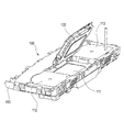
- FIG. 1 is a perspective view of a display unit in an embodiment of a vehicle instrument device according to the present invention.
- FIG. 2 is a development view of the display unit shown in FIG.
- FIG. 3 is a perspective view of a conventional vehicle instrument device.
- FIG. 1 is a perspective view of a display unit in an embodiment of a vehicle instrument device according to the present invention
- FIG. 2 is a development view of the display unit shown in FIG.
- the vehicle instrument device 1 is a combination meter disposed on a dashboard of a vehicle.
- a pointer-type meter 50 and a liquid crystal display unit (display unit) 10 are provided on a device housing (not shown). It is installed side by side.
- Examples of the pointer-type meter 50 include a speedometer and a tachometer.
- an LCD control circuit board (display control circuit board) 20 is detachably attached to the back surface of the liquid crystal display unit 10 which is a display unit.
- the LCD control circuit board 20 is a board for controlling the operation of the liquid crystal display unit 10, and is formed separately from the pointer control circuit board 60 for controlling the operation of the pointer-type instrument 50.
- the liquid crystal display unit 10 is juxtaposed with the pointer-type meter 50 as a liquid crystal display unit (display unit) 30 integrated with the LCD control circuit board 20.
- the liquid crystal display unit 10 covers a liquid crystal display panel 11 having a display surface 11 a for displaying an image, a box-shaped LCD case 15 covering the back side and the outer periphery of the liquid crystal display panel 11, and the back side of the LCD case 15.
- a metal bottom plate 16 and a metal bezel 18 that covers the periphery of the liquid crystal display panel 11 are provided.
- the box-type LCD case 15 is made of resin.
- the LCD case 15 includes a bottom wall portion 15a (see FIG. 2) that covers the back surface of the liquid crystal display panel 11 from the outside of the backlight, and a side wall portion 15b (see FIG. 1) that covers the outer periphery of the liquid crystal display panel 11. ing.
- the bottom plate 16 covers the bottom wall portion 15a of the LCD case 15 as shown in FIG.
- the bottom wall 15a of the LCD case 15 is provided with two mounting holes 151 for mounting the LCD control circuit board 20, two positioning pins 152, and two locking claws 153.
- the mounting hole 151, the positioning pin 152, and the locking claw 153 are all exposed outward from the notch 161 formed in the bottom plate 16.
- the two mounting holes 151 are holes for screwing the LCD control circuit board 20 and are formed with female screws.
- the two attachment holes 151 are provided at one diagonal on the rectangular bottom surface of the LCD case 15.
- the two positioning pins 152 have a structure in which a thin pin body 152b protrudes from the center of the large diameter boss portion 152a, and is provided at the other diagonal of the rectangular bottom surface of the LCD case 15. Each positioning pin 152 positions the LCD control circuit board 20 by inserting the pin main body 152b into a positioning hole 252 formed through the LCD control circuit board 20.
- the two locking claws 153 are engaged with the edge of the LCD control circuit board 20 when the LCD control circuit board 20 is positioned on the back surface of the liquid crystal display unit 10 by the two positioning pins 152, and the LCD control The circuit board 20 is temporarily fixed.
- an FPC (Flexible Printed Circuit) 19 for electrically connecting the liquid crystal display unit 10 and the LCD control circuit board 20 is drawn out.
- the FPC 19 is led out from the liquid crystal display unit 10, and the tip 19 a is connected to the LCD control circuit board 20 by the FPC connector 42.
- the part 191 laid on the bottom plate 16 of the FPC 19 is fixed in a state of surface contact with the bottom plate 16 by the adhesive mounting tape 170 and the pressing claws 157.
- an electronic component 192 is mounted on a portion 191 laid on the bottom plate 16 of the FPC 19.
- the tip 19a of the FPC 19 protrudes to the outside of the bottom plate 16, and as shown in FIG. 2, is connected to the FPC connector 42 on the LCD control circuit board 20 arranged in a plane adjacent to the liquid crystal display unit 10. Is done.
- the portion 193 of the FPC 19 that protrudes outside the bottom plate 16 is laid on the bottom plate 16 of the FPC 19 at the position of the broken line L1 in FIG. 2 when the LCD control circuit board 20 is attached to the back surface of the liquid crystal display unit 10. It is folded on the part 191 to be turned. That is, the portion 193 of the FPC 19 that protrudes outside the bottom plate 16 is folded between the portion 191 laid on the bottom plate 16 of the FPC 19 and accommodated between the liquid crystal display unit 10 and the LCD control circuit board 20. .
- the bezel 18 is a press-molded product made of a metal plate. As shown in FIG. 1, the front edge frame portion 181 that borders the display surface 11 a of the liquid crystal display panel 11 and the outside of the side wall portion 15 b of the LCD case 15. And an outer peripheral frame portion 182 that covers the outer periphery.
- an FPC cover portion 182 a is provided at a position facing the folded portion 19 b of the FPC 19 in the outer peripheral frame portion 182 of the bezel 18.
- the FPC cover 182a is formed longer in the thickness direction of the liquid crystal display unit 10 (the arrow X1 side in FIG. 1) than the surrounding outer peripheral frame 182 so as to cover the outside of the folded portion 19b of the FPC 19. .
- the LCD control circuit board 20 includes various electronic components 41a, 41b, 41c, 41d, and 41e for controlling the operation of the liquid crystal display unit 10, as shown in FIG.
- An FPC connector 42 and an external connection connector 43 are mounted.
- the LCD control circuit board 20 has a front view dimension set substantially the same as the front view dimension of the liquid crystal display unit 10. That is, in FIG. 2, the width dimension W1 of the liquid crystal display unit 10 and the width dimension W2 of the LCD control circuit board 20 are set to be approximately equal. In FIG. 2, the length dimension H1 of the liquid crystal display unit 10 and the length dimension H2 of the LCD control circuit board 20 are set to be approximately equal.
- the electronic component 41 a is a CPU (Central Processing Unit) and is located on the opposite side of the liquid crystal display unit 10. 21 is mounted on the outer surface 21a.
- the electronic component 41b is an LCD (Liquid Crystal Display) driver, and is mounted on the inner surface 21b of the multilayer substrate 21 located on the liquid crystal display unit 10 side.
- the FPC connector 42 mounted on the multilayer substrate 21 is a connector to which the tip 19a of the FPC 19 led to the back surface of the liquid crystal display unit 10 is connected.
- the FPC connector 42 is mounted on the inner surface 21 b of the multilayer substrate 21.
- the LCD control circuit board 20 is assembled to the back surface of the liquid crystal display unit 10 so that the inner surface 21b of the multilayer substrate 21 faces the back surface of the liquid crystal display unit 10.
- a regulation rib 158 protrudes at a position facing the FPC connector 42 on the LCD control circuit board 20.
- the restriction rib 158 is integrally formed with the bottom wall portion 15 a of the LCD case 15.
- the restriction rib 158 interferes with the FPC connector 42 when the LCD control circuit board 20 is assembled to the back surface of the liquid crystal display unit 10.
- the assembly of the LCD control circuit board 20 is disabled and a connection failure is detected.
- the external connection connector 43 mounted on the multilayer substrate 21 is a connector for connecting to an external circuit.
- the external connection connector 43 is mounted on the outer surface 21 a of the multilayer substrate 21.
- the external connection connector 43 is connected with a signal cable 71 for sending a signal necessary for the operation of the liquid crystal display unit 30, a power supply cable 73 for supplying power, and a GND cable 75 as external circuits.
- the multi-layer substrate 21 is provided with two mounting holes 251, two positioning holes 252, and two locking notches 253 for fixing to the back surface of the liquid crystal display unit 10.
- the two mounting holes 251 are holes corresponding to the mounting holes 151 on the back surface of the liquid crystal display unit 10 and are holes through which male screws that are screwed into the mounting holes 151 can be inserted.
- the two positioning holes 252 are holes corresponding to the positioning pins 152 on the back surface of the liquid crystal display unit 10.
- the two positioning holes 252 are positioned by inserting the pin main body 152b of the positioning pin 152.
- the two locking notches 253 are portions where the locking claws 153 on the back surface of the liquid crystal display unit 10 are engaged.
- a ground terminal 61 is provided on the inner surface 21 b of the multilayer substrate 21.
- the ground terminal 61 is made of metal and has a base end soldered on a grounding pattern (GND pattern) on the multilayer substrate 21.
- the ground terminal 61 has an LCD ground portion that elastically contacts the bottom plate 16 of the metal bezel 18 when the LCD control circuit board 20 is assembled to the liquid crystal display unit 10.
- the casing contact portion elastically contacts the bottom plate 16, and the bottom plate 16 and the GND pattern 23 are in a conductive state.
- the GND pattern on the multilayer substrate 21 to which the ground terminal 61 is soldered is connected to an external GND cable via the external connection connector 43.
- the GND pattern is provided at a position close to the external connection connector 43.
- the back surface of the liquid crystal display unit 10 and the LCD control circuit board 20 are arranged in a plane, and the tip 19a of the FPC 19 is an FPC connector on the inner surface 21b of the LCD control circuit board 20. 42.
- the FPC 19 is folded back at the position of the broken line L 1 in FIG. 2, and the inner surface 21 b of the LCD control circuit board 20 is overlaid on the back surface of the liquid crystal display unit 10.
- the positioning pins 152 of the liquid crystal display unit 10 and the positioning holes 252 of the LCD control circuit board 20 are aligned, so that the locking claws 153 of the liquid crystal display unit 10 are moved to the LCD as shown in FIG.
- the LCD control circuit board 20 is temporarily fixed to the back surface of the liquid crystal display unit 10 by being engaged with the locking notch 253 of the control circuit board 20.
- the male screw inserted into the mounting hole 251 of the LCD control circuit board 20 is screwed into the mounting hole 151 of the liquid crystal display unit 10, whereby the LCD control circuit board 20 is fixed to the back surface of the liquid crystal display unit 10, and the liquid crystal Assembling is completed as the display unit 30.
- the liquid crystal display unit 30 described above can function as, for example, an odometer indicating a travel distance, a fuel consumption meter, a gear position indicator, and the like.
- the LCD control circuit board 20 for controlling the operation of the liquid crystal display unit 10 is the pointer control circuit board for controlling the operation of the pointer-type instrument 50.
- 60 is a separate body. Therefore, even when a circuit board as the LCD control circuit board 20 uses a multilayer board having four or more layers, which is advantageous in achieving high-density mounting while ensuring reliability against noise resistance, the noise resistance is high.
- an inexpensive circuit board having three or less layers can be used as the circuit board as the pointer control circuit board 60 that is not required to be as good as the LCD control circuit board 20.
- the liquid crystal display unit 10 is juxtaposed with the pointer-type instrument 50 as the liquid crystal display unit 30 integrated with the LCD control circuit board 20.
- the pointer control circuit board 60 for controlling the operation of the pointer can be designed independently as a simple circuit board that does not include a circuit for controlling the operation of the liquid crystal display unit 10. Design can be made easy. Further, it is easy to share the liquid crystal display unit 10.
- the liquid crystal display unit 30 can be set to the minimum front view size. Assembling property (space property) can be made advantageous, and the maximum electronic component mounting area can be secured within the dimensions.
- the outer surface of the LCD control circuit board 20 provided with the external connection connector 43 (the outer surface 21 a of the multilayer board 21) is opposite to the liquid crystal display unit 10. It is a surface which is located on the outside and is exposed to the outside. Therefore, the external connection connector 43 is provided in a state exposed to the outside, and can be easily connected to an external circuit.
- the signal cable 71 for sending a signal necessary for the operation of the liquid crystal display unit 30 and the power supply cable 73 for supplying power are both outside the LCD control circuit board 20. It is connected to the external connection connector 43 on the surface. Therefore, the connection work of each cable can be facilitated.
- this invention is not limited to embodiment mentioned above, A deformation
- the material, shape, dimensions, number, arrangement location, and the like of each component in the above-described embodiment are arbitrary and are not limited as long as the present invention can be achieved.
- the liquid crystal display unit 10 and the LCD control circuit board 20 have been described as examples.
- other display units such as an organic EL display unit and an organic EL display control circuit board, and a display control circuit board. Of course, can be used.
- a vehicle instrument device (1) in which a pointer-type instrument (50) and a display unit (liquid crystal display unit 10) are provided in parallel,
- a display control circuit board (LCD control circuit board 20) for controlling the operation of the display unit (liquid crystal display unit 10) is a pointer control circuit board (60) for controlling the operation of the pointer-type instrument (50).
- a front view dimension is set to be substantially the same as the front view dimension of the liquid crystal display unit (liquid crystal display unit 10), and is assembled to the back surface of the liquid crystal display unit (liquid crystal display unit 10).
- the liquid crystal display unit (liquid crystal display unit 10) is arranged in parallel with the pointer-type instrument (50) as a display unit (liquid crystal display unit 30) integrated with the display control circuit board (LCD control circuit board 20).
- Vehicle instrument device (1) in which a pointer-type instrument (50) and a display unit (liquid crystal display unit 10) are provided in parallel
- the control circuit board (LCD control circuit board 20) includes an external connection connector (43) for connecting to an external circuit on an outer surface located on the opposite side of the display unit (liquid crystal display unit 10).
- the control circuit board includes an external connection connector (43) for connecting to an external circuit on an outer surface located on the opposite side of the display unit (liquid crystal display unit 10).
- the vehicle instrument device (1) Connected to the external connector (43) are a signal cable (71) for sending a signal necessary for the operation of the display unit (liquid crystal display unit 30) and a power cable (73) for supplying power as the external circuit. Vehicle instrument device (1).
- the display unit is a liquid crystal display unit (10), The vehicle instrument device (1), wherein the display control circuit board is an LCD control circuit board (20).
- the pointer control circuit board for controlling the operation of the pointer-type instrument becomes excessive quality. Can be prevented and the cost can be reduced.
- liquid crystal display unit (display unit) 20 LCD control circuit board (display control circuit board) 30 Liquid crystal display unit (display unit) 43 External connection connector 50 Pointer type instrument 60 Pointer control circuit board 71 Signal cable 73 Power cable
Landscapes
- Engineering & Computer Science (AREA)
- Chemical & Material Sciences (AREA)
- Combustion & Propulsion (AREA)
- Transportation (AREA)
- Mechanical Engineering (AREA)
- Instrument Panels (AREA)
- Liquid Crystal (AREA)
- Devices For Indicating Variable Information By Combining Individual Elements (AREA)
Abstract
A circuit board (20) for LCD control, for controlling the operation of a liquid crystal display unit (10), is assembled on the rear surface of the liquid crystal display unit (10), separate from a circuit board (60) for pointer control for controlling the operation of a pointer-type instrument (50), and has the dimensions thereof as viewed from the front surface set to be substantially the same as the dimensions, as viewed from the front surface, of the liquid crystal display unit (10). The liquid crystal display unit (10) is arranged alongside the pointer-type instrument (50), as a liquid crystal display unit (30) that is integral with the circuit board (20) for LCD control.
Description
本発明は、指針式計器とディスプレイユニットとが並設される車両用計器装置に関する。
The present invention relates to a vehicle instrument device in which a pointer-type instrument and a display unit are arranged in parallel.
図3は、下記特許文献1に開示された車両用計器装置を示している。
この車両用計器装置100は、車両のダッシュボードに配置される複合メータ(コンビネーションメータ)であり、装置筐体110上には、速度計や回転計などの指針式計器(不図示)と、液晶ディスプレイユニット(ディスプレイユニット)120とが並設される構造である。 FIG. 3 shows a vehicle instrument device disclosed in Patent Document 1 below.
Thevehicle instrument device 100 is a composite meter (combination meter) disposed on a dashboard of a vehicle. On the device housing 110, a pointer-type meter (not shown) such as a speedometer and a tachometer, and a liquid crystal The display unit (display unit) 120 is arranged in parallel.
この車両用計器装置100は、車両のダッシュボードに配置される複合メータ(コンビネーションメータ)であり、装置筐体110上には、速度計や回転計などの指針式計器(不図示)と、液晶ディスプレイユニット(ディスプレイユニット)120とが並設される構造である。 FIG. 3 shows a vehicle instrument device disclosed in Patent Document 1 below.
The
装置筐体110の中央部には、ディスプレイ収容空間111が確保されている。ディスプレイ収容空間111は、液晶ディスプレイユニット120が組み込まれる空間である。この液晶ディスプレイユニット120は、多機能に動作することができ、例えば、走行距離を示すオドメータや、燃費計や、ギヤポジションインジケータなどとして機能することができる。
A display accommodation space 111 is secured at the center of the apparatus housing 110. The display housing space 111 is a space in which the liquid crystal display unit 120 is incorporated. The liquid crystal display unit 120 can operate with multiple functions, and can function as, for example, an odometer that indicates a travel distance, a fuel consumption meter, a gear position indicator, and the like.
図3に示した装置筐体110は、指針式計器である速度計が配置される速度計配置部112と、指針式計器である回転計が配置される回転計配置部113とが設けられている。
The apparatus housing 110 shown in FIG. 3 is provided with a speedometer placement section 112 in which a speedometer as a pointer-type instrument is placed and a tachometer placement section 113 in which a tachometer as a pointer-type instrument is placed. Yes.
即ち、図3に示した車両用計器装置100は、液晶ディスプレイユニット120の両側に、それぞれ指針式計器が配置されるデザインになっている。
That is, the vehicle instrument device 100 shown in FIG. 3 is designed such that pointer-type instruments are arranged on both sides of the liquid crystal display unit 120, respectively.
従来の車両用計器装置の場合、液晶ディスプレイユニットの動作を制御するための電子回路や、指針式計器の動作を制御するための電子回路は、いずれも共通の一枚の回路基板上に形成されることが多い。
In the case of a conventional vehicle instrument device, the electronic circuit for controlling the operation of the liquid crystal display unit and the electronic circuit for controlling the operation of the pointer-type instrument are both formed on a common circuit board. Often.
ところで、液晶ディスプレイユニットや有機ELディスプレイユニット等のディスプレイユニットの動作を制御するための電子回路の場合、画像データ処理用のCPUを始めとして集積度の高い回路素子が使用されることが多い。そのため、耐ノイズ性に対する信頼性を確保すると同時に高密度実装を実現する観点から、回路基板としては例えば4層以上の多層基板の使用が要求される。
Incidentally, in the case of an electronic circuit for controlling the operation of a display unit such as a liquid crystal display unit or an organic EL display unit, a highly integrated circuit element such as a CPU for image data processing is often used. For this reason, from the viewpoint of ensuring reliability against noise resistance and at the same time realizing high-density mounting, it is required to use, for example, a multilayer board having four or more layers as the circuit board.
一方、指針式計器の動作を制御するための電子回路の場合は、ディスプレイユニットの動作を制御する電子回路と比較すると、使用する回路素子の集積度が低く、耐ノイズ性や実装性を考慮しても、4層以上の多層基板は必要とならない。
On the other hand, in the case of an electronic circuit for controlling the operation of a pointer-type meter, the degree of integration of circuit elements to be used is low compared to an electronic circuit for controlling the operation of a display unit, and noise resistance and mountability are taken into consideration. However, a multilayer substrate having four or more layers is not required.
従って、ディスプレイユニットの動作を制御するための電子回路と、指針式計器の動作を制御するための電子回路とが、共通の一枚の回路基板上に形成される場合には、ディスプレイユニット用の電子回路に対する要求を満足させる観点から、回路基板としては4層以上の多層基板が使用される。そこで、その回路基板は指針式計器用の電子回路に対しては過剰品質となって、車両用計器装置の高額化を招く要因となる。
Therefore, when the electronic circuit for controlling the operation of the display unit and the electronic circuit for controlling the operation of the pointer-type meter are formed on a common circuit board, the display unit From the viewpoint of satisfying the requirements for electronic circuits, a multilayer substrate having four or more layers is used as the circuit substrate. Therefore, the circuit board becomes an excessive quality with respect to the electronic circuit for the pointer-type instrument, which causes an increase in the cost of the vehicle instrument device.
そこで、本発明の目的は、上記課題を解消することに係り、指針式計器とディスプレイユニットとが並設される車両用計器装置において、指針式計器の動作を制御するための指針制御用回路基板が過剰品質になることを防止して、低コスト化を図ることのできる車両用計器装置を提供すること。
Accordingly, an object of the present invention is to solve the above-mentioned problems, and in a vehicle instrument device in which a pointer-type instrument and a display unit are provided in parallel, a pointer control circuit board for controlling the operation of the pointer-type instrument Is to provide an instrument device for a vehicle that can reduce the cost by preventing excessive quality.
本発明の前述した目的は、下記の構成により達成される。
(1) 指針式計器とディスプレイユニットとが並設される車両用計器装置であって、
前記ディスプレイユニットの動作を制御するためのディスプレイ制御用回路基板は、前記指針式計器の動作を制御するための指針制御用回路基板とは別体で、正面視寸法が前記ディスプレイユニットの正面視寸法と略同一に設定されると共に、前記ディスプレイユニットの裏面に組み付けられ、
前記ディスプレイユニットは、前記ディスプレイ制御用回路基板と一体化された表示ユニットとして前記指針式計器に並設される車両用計器装置。 The above-described object of the present invention is achieved by the following configuration.
(1) A vehicle instrument device in which a pointer-type instrument and a display unit are juxtaposed,
The display control circuit board for controlling the operation of the display unit is separate from the pointer control circuit board for controlling the operation of the pointer-type instrument, and the front view dimension is the front view dimension of the display unit. Is set to be substantially the same as that and assembled to the back surface of the display unit,
The display instrument is a vehicle instrument device arranged in parallel with the pointer-type instrument as a display unit integrated with the display control circuit board.
(2) 上記(1)に記載の車両用計器装置であって、
前記ディスプレイ制御用回路基板は、前記ディスプレイユニットとは反対側に位置する外表面に、外部回路と接続するための外部接続コネクタが備えられている車両用計器装置。 (2) The vehicle instrument device according to (1) above,
The display control circuit board is a vehicular instrument device in which an external connection connector for connecting to an external circuit is provided on an outer surface located on the opposite side of the display unit.
(3) 上記(2)に記載の車両用計器装置であって、
前記外部接続コネクタには、前記外部回路として、前記表示ユニットの動作に必要な信号を送る信号ケーブルと、給電を行う電源ケーブルとが接続される車両用計器装置。 (3) The vehicle instrument device according to (2) above,
A vehicle instrument device in which a signal cable for sending a signal necessary for the operation of the display unit and a power cable for supplying power are connected to the external connection connector as the external circuit.
(4) 上記(1)~(3)の何れか1つに記載の車両用計器装置において、
前記ディスプレイユニットが、液晶ディスプレイユニットであって、
前記ディスプレイ制御用回路基板が、LCD制御用回路基板である車両用計器装置。 (4) In the vehicle instrument device described in any one of (1) to (3) above,
The display unit is a liquid crystal display unit,
An instrument device for a vehicle, wherein the display control circuit board is an LCD control circuit board.
上記(1)の構成によれば、ディスプレイユニットの動作を制御するためのディスプレイ制御用回路基板は、指針式計器の動作を制御するための指針制御用回路基板とは別体である。従って、ディスプレイ制御用回路基板としての回路基板には、耐ノイズ性に対する信頼性を確保すると同時に高密度実装を実現する上で有利な4層以上の多層基板を使用する場合でも、耐ノイズ性や実装性がディスプレイ制御用回路基板ほど要求されない指針制御用回路基板としての回路基板には、例えば、3層以下の安価な回路基板を使用することができる。
According to the configuration of (1) above, the display control circuit board for controlling the operation of the display unit is separate from the pointer control circuit board for controlling the operation of the pointer-type instrument. Therefore, even when a circuit board as a display control circuit board uses a multilayer board of four or more layers, which is advantageous for realizing high-density mounting while ensuring reliability against noise resistance, noise resistance and For example, an inexpensive circuit board having three or less layers can be used as a circuit board as a pointer control circuit board that is not required to be mounted as easily as a display control circuit board.
従って、ディスプレイユニットに並設される指針式計器の動作を制御するための指針制御用回路基板が過剰品質になることを防止して、低コスト化を図ることができる。
Therefore, it is possible to prevent the pointer control circuit board for controlling the operation of the pointer-type meters arranged in parallel with the display unit from becoming excessive quality and to reduce the cost.
また、上記(1)の構成によれば、ディスプレイユニットは、ディスプレイ制御用回路基板と一体化された表示ユニットとして指針式計器に並設されるため、指針式計器の動作を制御するための指針制御用回路基板は、ディスプレイユニットの動作を制御するための回路を含まない単純な回路基板として単独で設計することができ、指針制御用回路基板の設計を容易にすることができる。また、ディスプレイユニットの共用も図り易い。
Further, according to the configuration of (1), the display unit is arranged in parallel with the pointer-type instrument as a display unit integrated with the display control circuit board, so that the pointer for controlling the operation of the pointer-type instrument is provided. The control circuit board can be designed independently as a simple circuit board that does not include a circuit for controlling the operation of the display unit, and the design of the pointer control circuit board can be facilitated. In addition, it is easy to share the display unit.
上記(2)の構成によれば、外部接続コネクタが装備されているディスプレイ制御用回路基板の外表面は、ディスプレイユニットとは反対側に位置する面で、外部に露出している面である。従って、外部接続コネクタは外部に露出した状態に装備されており、外部回路への接続が容易にできる。
According to the configuration of (2) above, the outer surface of the display control circuit board equipped with the external connector is a surface located on the side opposite to the display unit and exposed to the outside. Therefore, the external connection connector is provided in a state exposed to the outside, and can be easily connected to an external circuit.
上記(3)の構成によれば、表示ユニットの動作に必要な信号を送る信号ケーブルと、給電を行う電源ケーブルとは、いずれも、ディスプレイ制御用回路基板の外表面の外部接続コネクタに接続されるため、それぞれのケーブルの接続作業を容易にすることができる。
According to the configuration of (3) above, both the signal cable for sending a signal necessary for the operation of the display unit and the power cable for supplying power are connected to the external connection connector on the outer surface of the display control circuit board. Therefore, connection work of each cable can be facilitated.
以上、本発明について簡潔に説明した。更に、以下に説明される発明を実施するための形態(以下、「実施形態」という。)を添付の図面を参照して通読することにより、本発明の詳細は更に明確化されるであろう。
The present invention has been briefly described above. Further, the details of the present invention will be further clarified by reading through a mode for carrying out the invention described below (hereinafter referred to as “embodiment”) with reference to the accompanying drawings. .
以下、本発明に係る車両用計器装置の好適な実施形態について、図面を参照して詳細に説明する。
Hereinafter, preferred embodiments of a vehicle instrument device according to the present invention will be described in detail with reference to the drawings.
図1は本発明に係る車両用計器装置の一実施形態における表示ユニットの斜視図、図2は図1に示した表示ユニットの展開図である。
FIG. 1 is a perspective view of a display unit in an embodiment of a vehicle instrument device according to the present invention, and FIG. 2 is a development view of the display unit shown in FIG.
この一実施形態の車両用計器装置1は、車両のダッシュボードに配置されるコンビネーションメータであり、不図示の装置筐体上に、指針式計器50と、液晶ディスプレイユニット(ディスプレイユニット)10とが並設される。
The vehicle instrument device 1 according to this embodiment is a combination meter disposed on a dashboard of a vehicle. A pointer-type meter 50 and a liquid crystal display unit (display unit) 10 are provided on a device housing (not shown). It is installed side by side.
指針式計器50としては、例えば、速度計や回転計などがある。
Examples of the pointer-type meter 50 include a speedometer and a tachometer.
本実施形態の場合、ディスプレイユニットである液晶ディスプレイユニット10の裏面には、LCD制御用回路基板(ディスプレイ制御用回路基板)20が着脱可能に取り付けられる。LCD制御用回路基板20は、液晶ディスプレイユニット10の動作を制御するための基板であり、指針式計器50の動作を制御するための指針制御用回路基板60とは別体に形成されている。また、本実施形態の場合、液晶ディスプレイユニット10は、LCD制御用回路基板20と一体化された液晶表示ユニット(表示ユニット)30として、指針式計器50に並設される。
In the case of this embodiment, an LCD control circuit board (display control circuit board) 20 is detachably attached to the back surface of the liquid crystal display unit 10 which is a display unit. The LCD control circuit board 20 is a board for controlling the operation of the liquid crystal display unit 10, and is formed separately from the pointer control circuit board 60 for controlling the operation of the pointer-type instrument 50. In the case of this embodiment, the liquid crystal display unit 10 is juxtaposed with the pointer-type meter 50 as a liquid crystal display unit (display unit) 30 integrated with the LCD control circuit board 20.
以下、本実施形態に係る液晶表示ユニット30の構成部品について、詳述する。
液晶ディスプレイユニット10は、画像を表示する表示面11aを有した液晶ディスプレイパネル11と、該液晶ディスプレイパネル11の裏面側及び外周を覆う箱型のLCDケース15と、このLCDケース15の裏面を覆う金属製の底板16と、液晶ディスプレイパネル11の周囲を覆う金属製のベゼル18と、を備えている。 Hereinafter, the components of the liquidcrystal display unit 30 according to the present embodiment will be described in detail.
The liquidcrystal display unit 10 covers a liquid crystal display panel 11 having a display surface 11 a for displaying an image, a box-shaped LCD case 15 covering the back side and the outer periphery of the liquid crystal display panel 11, and the back side of the LCD case 15. A metal bottom plate 16 and a metal bezel 18 that covers the periphery of the liquid crystal display panel 11 are provided.
液晶ディスプレイユニット10は、画像を表示する表示面11aを有した液晶ディスプレイパネル11と、該液晶ディスプレイパネル11の裏面側及び外周を覆う箱型のLCDケース15と、このLCDケース15の裏面を覆う金属製の底板16と、液晶ディスプレイパネル11の周囲を覆う金属製のベゼル18と、を備えている。 Hereinafter, the components of the liquid
The liquid
液晶ディスプレイパネル11の裏面には、図示していないが、液晶を照明するバックライトが配置されている。箱型のLCDケース15は、樹脂製である。このLCDケース15は、バックライトの外側から液晶ディスプレイパネル11の裏面を覆う底壁部15a(図2参照)と、液晶ディスプレイパネル11の外周を覆う側壁部15b(図1参照)と、を備えている。
Although not shown, a backlight for illuminating the liquid crystal is disposed on the back surface of the liquid crystal display panel 11. The box-type LCD case 15 is made of resin. The LCD case 15 includes a bottom wall portion 15a (see FIG. 2) that covers the back surface of the liquid crystal display panel 11 from the outside of the backlight, and a side wall portion 15b (see FIG. 1) that covers the outer periphery of the liquid crystal display panel 11. ing.
底板16は、図2に示すように、LCDケース15の底壁部15aを覆っている。
The bottom plate 16 covers the bottom wall portion 15a of the LCD case 15 as shown in FIG.
LCDケース15の底壁部15aには、LCD制御用回路基板20を取り付けるための2つの取付孔151と、2つの位置決めピン152と、2つの係止爪153と、が設けられる。これらの取付孔151、位置決めピン152、係止爪153は、いずれも、底板16に形成された切欠161から外方に露出する。
The bottom wall 15a of the LCD case 15 is provided with two mounting holes 151 for mounting the LCD control circuit board 20, two positioning pins 152, and two locking claws 153. The mounting hole 151, the positioning pin 152, and the locking claw 153 are all exposed outward from the notch 161 formed in the bottom plate 16.
2つの取付孔151は、LCD制御用回路基板20をねじ止めするための孔で、雌ねじが形成されている。2つの取付孔151は、LCDケース15の矩形の底面における一方の対角に設けられている。
The two mounting holes 151 are holes for screwing the LCD control circuit board 20 and are formed with female screws. The two attachment holes 151 are provided at one diagonal on the rectangular bottom surface of the LCD case 15.
2つの位置決めピン152は、太径のボス部152aの中心に細径のピン本体152bが突設された構造で、LCDケース15の矩形の底面における他方の対角に設けられている。それぞれの位置決めピン152は、LCD制御用回路基板20に貫通形成された位置決め孔252にピン本体152bが挿通されることで、LCD制御用回路基板20が位置決めされる。
The two positioning pins 152 have a structure in which a thin pin body 152b protrudes from the center of the large diameter boss portion 152a, and is provided at the other diagonal of the rectangular bottom surface of the LCD case 15. Each positioning pin 152 positions the LCD control circuit board 20 by inserting the pin main body 152b into a positioning hole 252 formed through the LCD control circuit board 20.
2つの係止爪153は、2つの位置決めピン152により液晶ディスプレイユニット10の裏面にLCD制御用回路基板20が位置決めされた時に、LCD制御用回路基板20の縁に係合されて、該LCD制御用回路基板20が仮止めされる。
The two locking claws 153 are engaged with the edge of the LCD control circuit board 20 when the LCD control circuit board 20 is positioned on the back surface of the liquid crystal display unit 10 by the two positioning pins 152, and the LCD control The circuit board 20 is temporarily fixed.
底板16の中央には、液晶ディスプレイユニット10とLCD制御用回路基板20とを電気的に接続するためのFPC(Flexible Printed Circuit)19が引き出されている。このFPC19は、液晶ディスプレイユニット10から導出されており、先端19aは、FPCコネクタ42によりLCD制御用回路基板20に接続される。
At the center of the bottom plate 16, an FPC (Flexible Printed Circuit) 19 for electrically connecting the liquid crystal display unit 10 and the LCD control circuit board 20 is drawn out. The FPC 19 is led out from the liquid crystal display unit 10, and the tip 19 a is connected to the LCD control circuit board 20 by the FPC connector 42.
FPC19の底板16上に敷設される部位191は、粘着性の取り付けテープ170と押さえ爪157とによって、底板16に面接触した状態に固定される。本実施形態の場合、FPC19の底板16上に敷設される部位191には、電子部品192が搭載されている。
The part 191 laid on the bottom plate 16 of the FPC 19 is fixed in a state of surface contact with the bottom plate 16 by the adhesive mounting tape 170 and the pressing claws 157. In the case of this embodiment, an electronic component 192 is mounted on a portion 191 laid on the bottom plate 16 of the FPC 19.
FPC19の先端19aは、底板16の外側に張り出しており、図2に示すように、液晶ディスプレイユニット10に隣接する状態に平面状に敷き並べたLCD制御用回路基板20上のFPCコネクタ42に接続される。底板16の外側に張り出したFPC19の部位193は、LCD制御用回路基板20が液晶ディスプレイユニット10の裏面に取り付けられた際に、図2の破線L1の位置で、FPC19の底板16上に敷設される部位191の上に折り返される。即ち、底板16の外側に張り出しFPC19の部位193は、FPC19の底板16上に敷設される部位191の上に折り重なる形態で、液晶ディスプレイユニット10とLCD制御用回路基板20との間に収容される。
The tip 19a of the FPC 19 protrudes to the outside of the bottom plate 16, and as shown in FIG. 2, is connected to the FPC connector 42 on the LCD control circuit board 20 arranged in a plane adjacent to the liquid crystal display unit 10. Is done. The portion 193 of the FPC 19 that protrudes outside the bottom plate 16 is laid on the bottom plate 16 of the FPC 19 at the position of the broken line L1 in FIG. 2 when the LCD control circuit board 20 is attached to the back surface of the liquid crystal display unit 10. It is folded on the part 191 to be turned. That is, the portion 193 of the FPC 19 that protrudes outside the bottom plate 16 is folded between the portion 191 laid on the bottom plate 16 of the FPC 19 and accommodated between the liquid crystal display unit 10 and the LCD control circuit board 20. .
ベゼル18は、金属板製のプレス成形品であり、図1に示すように、液晶ディスプレイパネル11の表示面11aの周囲を縁取る前縁枠部181と、LCDケース15の側壁部15bの外側を覆う外周枠部182と、を備えている。
The bezel 18 is a press-molded product made of a metal plate. As shown in FIG. 1, the front edge frame portion 181 that borders the display surface 11 a of the liquid crystal display panel 11 and the outside of the side wall portion 15 b of the LCD case 15. And an outer peripheral frame portion 182 that covers the outer periphery.
ベゼル18の外周枠部182のうち、FPC19の折り返し部19bと対向する位置には、図1に示すように、FPC覆い部182aが設けられている。このFPC覆い部182aは、FPC19の折り返し部19bの外側を覆うように、周囲の外周枠部182よりも、液晶ディスプレイユニット10の厚さ方向(図1の矢印X1側)に長く形成されている。
As shown in FIG. 1, an FPC cover portion 182 a is provided at a position facing the folded portion 19 b of the FPC 19 in the outer peripheral frame portion 182 of the bezel 18. The FPC cover 182a is formed longer in the thickness direction of the liquid crystal display unit 10 (the arrow X1 side in FIG. 1) than the surrounding outer peripheral frame 182 so as to cover the outside of the folded portion 19b of the FPC 19. .
LCD制御用回路基板20は、4層以上の多層基板21に、図2に示すように、液晶ディスプレイユニット10の動作を制御するための各種の電子部品41a,41b,41c,41d,41eと、FPCコネクタ42と、外部接続コネクタ43と、を搭載したものである。
As shown in FIG. 2, the LCD control circuit board 20 includes various electronic components 41a, 41b, 41c, 41d, and 41e for controlling the operation of the liquid crystal display unit 10, as shown in FIG. An FPC connector 42 and an external connection connector 43 are mounted.
本実施形態の場合、LCD制御用回路基板20は、その正面視寸法が前記液晶ディスプレイユニット10の正面視寸法と略同一に設定されている。即ち、図2において、液晶ディスプレイユニット10の幅寸法W1とLCD制御用回路基板20の幅寸法W2とは略等しく設定されている。また、図2において、液晶ディスプレイユニット10の長さ寸法H1とLCD制御用回路基板20の長さ寸法H2とは、略等しく設定されている。
In the case of the present embodiment, the LCD control circuit board 20 has a front view dimension set substantially the same as the front view dimension of the liquid crystal display unit 10. That is, in FIG. 2, the width dimension W1 of the liquid crystal display unit 10 and the width dimension W2 of the LCD control circuit board 20 are set to be approximately equal. In FIG. 2, the length dimension H1 of the liquid crystal display unit 10 and the length dimension H2 of the LCD control circuit board 20 are set to be approximately equal.
多層基板21に搭載される各種の電子部品41a,41b,41c,41d,41eの内、電子部品41aは、CPU(Central Processing Unit)であり、液晶ディスプレイユニット10とは反対側に位置する多層基板21の外表面21aに搭載されている。電子部品41bは、LCD(Liquid Crystal Display)ドライバであり、液晶ディスプレイユニット10側に位置する多層基板21の内表面21bに搭載されている。
Of the various electronic components 41 a, 41 b, 41 c, 41 d, 41 e mounted on the multilayer substrate 21, the electronic component 41 a is a CPU (Central Processing Unit) and is located on the opposite side of the liquid crystal display unit 10. 21 is mounted on the outer surface 21a. The electronic component 41b is an LCD (Liquid Crystal Display) driver, and is mounted on the inner surface 21b of the multilayer substrate 21 located on the liquid crystal display unit 10 side.
多層基板21に搭載されるFPCコネクタ42は、液晶ディスプレイユニット10の裏面に導出されたFPC19の先端19aが接続されるコネクタである。FPCコネクタ42は、多層基板21の内表面21bに搭載されている。
The FPC connector 42 mounted on the multilayer substrate 21 is a connector to which the tip 19a of the FPC 19 led to the back surface of the liquid crystal display unit 10 is connected. The FPC connector 42 is mounted on the inner surface 21 b of the multilayer substrate 21.
LCD制御用回路基板20は、多層基板21の内表面21bが液晶ディスプレイユニット10の裏面と対向するように、液晶ディスプレイユニット10の裏面に組み付けられる。
The LCD control circuit board 20 is assembled to the back surface of the liquid crystal display unit 10 so that the inner surface 21b of the multilayer substrate 21 faces the back surface of the liquid crystal display unit 10.
液晶ディスプレイユニット10の裏面において、LCD制御用回路基板20上のFPCコネクタ42と対向する位置には、規制リブ158が突設されている。この規制リブ158は、LCDケース15の底壁部15aに一体形成されている。この規制リブ158は、FPC19の先端19aのFPCコネクタ42への接続が不完全の場合には、LCD制御用回路基板20が液晶ディスプレイユニット10の裏面に組み付けられた際にFPCコネクタ42と干渉して、LCD制御用回路基板20の組み付けを不能にすると共に、接続不良を検知させる。
On the back surface of the liquid crystal display unit 10, a regulation rib 158 protrudes at a position facing the FPC connector 42 on the LCD control circuit board 20. The restriction rib 158 is integrally formed with the bottom wall portion 15 a of the LCD case 15. When the connection of the tip 19a of the FPC 19 to the FPC connector 42 is incomplete, the restriction rib 158 interferes with the FPC connector 42 when the LCD control circuit board 20 is assembled to the back surface of the liquid crystal display unit 10. Thus, the assembly of the LCD control circuit board 20 is disabled and a connection failure is detected.
多層基板21に搭載される外部接続コネクタ43は、外部回路と接続するためのコネクタである。この外部接続コネクタ43は、多層基板21の外表面21aに搭載されている。また、この外部接続コネクタ43には、外部回路として、液晶表示ユニット30の動作に必要な信号を送る信号ケーブル71と、給電を行う電源ケーブル73と、GNDケーブル75とが接続される。
The external connection connector 43 mounted on the multilayer substrate 21 is a connector for connecting to an external circuit. The external connection connector 43 is mounted on the outer surface 21 a of the multilayer substrate 21. The external connection connector 43 is connected with a signal cable 71 for sending a signal necessary for the operation of the liquid crystal display unit 30, a power supply cable 73 for supplying power, and a GND cable 75 as external circuits.
多層基板21には、液晶ディスプレイユニット10の裏面に固定するために、2つの取付孔251と、2つの位置決め孔252と、2つの係止用切欠253とが設けられている。
The multi-layer substrate 21 is provided with two mounting holes 251, two positioning holes 252, and two locking notches 253 for fixing to the back surface of the liquid crystal display unit 10.
2つの取付孔251は、液晶ディスプレイユニット10の裏面の取付孔151に対応する孔で、取付孔151に螺着する雄ねじを挿通可能な孔である。
The two mounting holes 251 are holes corresponding to the mounting holes 151 on the back surface of the liquid crystal display unit 10 and are holes through which male screws that are screwed into the mounting holes 151 can be inserted.
2つの位置決め孔252は、液晶ディスプレイユニット10の裏面の位置決めピン152に対応する孔である。2つの位置決め孔252は、位置決めピン152のピン本体152bが挿通されることで、位置決めされる。
The two positioning holes 252 are holes corresponding to the positioning pins 152 on the back surface of the liquid crystal display unit 10. The two positioning holes 252 are positioned by inserting the pin main body 152b of the positioning pin 152.
2つの係止用切欠253は、液晶ディスプレイユニット10の裏面の係止爪153が係合する部位である。
The two locking notches 253 are portions where the locking claws 153 on the back surface of the liquid crystal display unit 10 are engaged.
また、本実施形態の場合、多層基板21の内表面21bには、アース端子61が設けられている。このアース端子61は、金属製で、基端が多層基板21上の接地用パターン(GNDパターン)の上に半田付けされている。アース端子61は、LCD制御用回路基板20を液晶ディスプレイユニット10に組み付けた際に、金属製のベゼル18の底板16に弾性接触するLCD接地部を有している。
In the case of the present embodiment, a ground terminal 61 is provided on the inner surface 21 b of the multilayer substrate 21. The ground terminal 61 is made of metal and has a base end soldered on a grounding pattern (GND pattern) on the multilayer substrate 21. The ground terminal 61 has an LCD ground portion that elastically contacts the bottom plate 16 of the metal bezel 18 when the LCD control circuit board 20 is assembled to the liquid crystal display unit 10.
本実施形態のアース端子61は、LCD制御用回路基板20が液晶ディスプレイユニット10に組み付けられた際に、筐体接触部が底板16に弾性接触して、底板16とGNDパターン23とを導通状態にする。
In the ground terminal 61 of the present embodiment, when the LCD control circuit board 20 is assembled to the liquid crystal display unit 10, the casing contact portion elastically contacts the bottom plate 16, and the bottom plate 16 and the GND pattern 23 are in a conductive state. To.
本実施形態の場合、アース端子61が半田付けされる多層基板21上のGNDパターンは、外部接続コネクタ43を介して外部のGNDケーブルに接続される。GNDパターンの敷設長をできるだけ短くするために、本実施形態では、GNDパターンが、外部接続コネクタ43に近接する位置に設けられている。
In the case of this embodiment, the GND pattern on the multilayer substrate 21 to which the ground terminal 61 is soldered is connected to an external GND cable via the external connection connector 43. In order to make the laying length of the GND pattern as short as possible, in the present embodiment, the GND pattern is provided at a position close to the external connection connector 43.
LCD制御用回路基板20が液晶ディスプレイユニット10の裏面に組み付けられる作業は、次の手順で行われる。
The operation of assembling the LCD control circuit board 20 on the back surface of the liquid crystal display unit 10 is performed according to the following procedure.
まず、図2に示すように、液晶ディスプレイユニット10の裏面とLCD制御用回路基板20とが平面状に敷き並べられて、FPC19の先端19aがLCD制御用回路基板20の内表面21bのFPCコネクタ42に接続される。
First, as shown in FIG. 2, the back surface of the liquid crystal display unit 10 and the LCD control circuit board 20 are arranged in a plane, and the tip 19a of the FPC 19 is an FPC connector on the inner surface 21b of the LCD control circuit board 20. 42.
次いで、図2の破線L1の位置でFPC19が折り返されて、LCD制御用回路基板20の内表面21bが、液晶ディスプレイユニット10の裏面に重ねられる。その時、液晶ディスプレイユニット10の位置決めピン152と、LCD制御用回路基板20の位置決め孔252とが位置合わせされることで、図1に示すように、液晶ディスプレイユニット10の係止爪153が、LCD制御用回路基板20の係止用切欠253に係合されて、LCD制御用回路基板20が液晶ディスプレイユニット10の裏面に仮止めされた状態になる。
Next, the FPC 19 is folded back at the position of the broken line L 1 in FIG. 2, and the inner surface 21 b of the LCD control circuit board 20 is overlaid on the back surface of the liquid crystal display unit 10. At that time, the positioning pins 152 of the liquid crystal display unit 10 and the positioning holes 252 of the LCD control circuit board 20 are aligned, so that the locking claws 153 of the liquid crystal display unit 10 are moved to the LCD as shown in FIG. The LCD control circuit board 20 is temporarily fixed to the back surface of the liquid crystal display unit 10 by being engaged with the locking notch 253 of the control circuit board 20.
次いで、LCD制御用回路基板20の取付孔251に挿通させた雄ねじが液晶ディスプレイユニット10の取付孔151にねじ込まれることで、LCD制御用回路基板20が液晶ディスプレイユニット10の裏面に固定され、液晶表示ユニット30として組立が完了した状態になる。
Next, the male screw inserted into the mounting hole 251 of the LCD control circuit board 20 is screwed into the mounting hole 151 of the liquid crystal display unit 10, whereby the LCD control circuit board 20 is fixed to the back surface of the liquid crystal display unit 10, and the liquid crystal Assembling is completed as the display unit 30.
以上に説明した液晶表示ユニット30は、例えば、走行距離を示すオドメータや、燃費計や、ギヤポジションインジケータなどとして機能させることができる。
The liquid crystal display unit 30 described above can function as, for example, an odometer indicating a travel distance, a fuel consumption meter, a gear position indicator, and the like.
以上に説明した本実施形態の車両用計器装置1では、液晶ディスプレイユニット10の動作を制御するためのLCD制御用回路基板20は、指針式計器50の動作を制御するための指針制御用回路基板60とは別体である。従って、LCD制御用回路基板20としての回路基板には、耐ノイズ性に対する信頼性を確保すると同時に高密度実装を実現する上で有利な4層以上の多層基板が使用される場合でも、耐ノイズ性や実装性がLCD制御用回路基板20ほど要求されない指針制御用回路基板60としての回路基板には、例えば、3層以下の安価な回路基板を使用することができる。
In the vehicle instrument device 1 according to the present embodiment described above, the LCD control circuit board 20 for controlling the operation of the liquid crystal display unit 10 is the pointer control circuit board for controlling the operation of the pointer-type instrument 50. 60 is a separate body. Therefore, even when a circuit board as the LCD control circuit board 20 uses a multilayer board having four or more layers, which is advantageous in achieving high-density mounting while ensuring reliability against noise resistance, the noise resistance is high. For example, an inexpensive circuit board having three or less layers can be used as the circuit board as the pointer control circuit board 60 that is not required to be as good as the LCD control circuit board 20.
従って、液晶ディスプレイユニット10に並設される指針式計器50の動作を制御するための指針制御用回路基板60が過剰品質になることを防止して、低コスト化を図ることができる。
Therefore, it is possible to prevent the pointer control circuit board 60 for controlling the operation of the pointer-type meter 50 provided in parallel with the liquid crystal display unit 10 from becoming excessive quality, and to reduce the cost.
また、本実施形態の車両用計器装置1では、液晶ディスプレイユニット10は、LCD制御用回路基板20と一体化された液晶表示ユニット30として指針式計器50に並設されるため、指針式計器50の動作を制御するための指針制御用回路基板60は、液晶ディスプレイユニット10の動作を制御するための回路を含まない単純な回路基板として単独で設計することができ、指針制御用回路基板60の設計を容易にすることができる。また、液晶ディスプレイユニット10の共用も図り易い。
Further, in the vehicle instrument device 1 of the present embodiment, the liquid crystal display unit 10 is juxtaposed with the pointer-type instrument 50 as the liquid crystal display unit 30 integrated with the LCD control circuit board 20. The pointer control circuit board 60 for controlling the operation of the pointer can be designed independently as a simple circuit board that does not include a circuit for controlling the operation of the liquid crystal display unit 10. Design can be made easy. Further, it is easy to share the liquid crystal display unit 10.
また、LCD制御用回路基板20の正面視寸法が液晶ディスプレイユニット10の正面視寸法と略同一とされることにより、液晶表示ユニット30は最小正面視寸法とすることができ、車両用計器装置1への組付性(スペース性)を有利にでき、かつ、その寸法内で最大の電子部品実装面積を確保できる。
Further, since the front view size of the LCD control circuit board 20 is substantially the same as the front view size of the liquid crystal display unit 10, the liquid crystal display unit 30 can be set to the minimum front view size. Assembling property (space property) can be made advantageous, and the maximum electronic component mounting area can be secured within the dimensions.
また、本実施形態の車両用計器装置1では、外部接続コネクタ43が設けられているLCD制御用回路基板20の外表面(多層基板21の外表面21a)は、液晶ディスプレイユニット10とは反対側に位置する面であり、外部に露出している面である。従って、外部接続コネクタ43は外部に露出した状態に設けられており、外部回路への接続が容易にできる。
Further, in the vehicle instrument device 1 of the present embodiment, the outer surface of the LCD control circuit board 20 provided with the external connection connector 43 (the outer surface 21 a of the multilayer board 21) is opposite to the liquid crystal display unit 10. It is a surface which is located on the outside and is exposed to the outside. Therefore, the external connection connector 43 is provided in a state exposed to the outside, and can be easily connected to an external circuit.
また、本実施形態の車両用計器装置1では、液晶表示ユニット30の動作に必要な信号を送る信号ケーブル71と、給電を行う電源ケーブル73とは、いずれも、LCD制御用回路基板20の外表面の外部接続コネクタ43に接続される。そのため、それぞれのケーブルの接続作業を容易にすることができる。
Further, in the vehicle instrument device 1 of the present embodiment, the signal cable 71 for sending a signal necessary for the operation of the liquid crystal display unit 30 and the power supply cable 73 for supplying power are both outside the LCD control circuit board 20. It is connected to the external connection connector 43 on the surface. Therefore, the connection work of each cable can be facilitated.
なお、本発明は、上述した実施形態に限定されるものではなく、適宜、変形、改良、等が可能である。その他、上述した実施形態における各構成要素の材質、形状、寸法、数、配置箇所、等は本発明を達成できるものであれば任意であり、限定されない。
例えば、上記実施形態においては、液晶ディスプレイユニット10及びLCD制御用回路基板20を例に説明したが、有機ELディスプレイユニット及び有機ELディスプレイ制御用回路基板などの他のディスプレイユニット及びディスプレイ制御用回路基板を用いることができることは勿論である。 In addition, this invention is not limited to embodiment mentioned above, A deformation | transformation, improvement, etc. are possible suitably. In addition, the material, shape, dimensions, number, arrangement location, and the like of each component in the above-described embodiment are arbitrary and are not limited as long as the present invention can be achieved.
For example, in the above embodiment, the liquidcrystal display unit 10 and the LCD control circuit board 20 have been described as examples. However, other display units such as an organic EL display unit and an organic EL display control circuit board, and a display control circuit board. Of course, can be used.
例えば、上記実施形態においては、液晶ディスプレイユニット10及びLCD制御用回路基板20を例に説明したが、有機ELディスプレイユニット及び有機ELディスプレイ制御用回路基板などの他のディスプレイユニット及びディスプレイ制御用回路基板を用いることができることは勿論である。 In addition, this invention is not limited to embodiment mentioned above, A deformation | transformation, improvement, etc. are possible suitably. In addition, the material, shape, dimensions, number, arrangement location, and the like of each component in the above-described embodiment are arbitrary and are not limited as long as the present invention can be achieved.
For example, in the above embodiment, the liquid
ここで、上述した本発明に係る車両用計器装置の実施形態の特徴をそれぞれ以下[1]~[4]に簡潔に纏めて列記する。
Here, the features of the above-described embodiment of the vehicle instrument device according to the present invention are briefly summarized and listed in the following [1] to [4], respectively.
[1] 指針式計器(50)とディスプレイユニット(液晶ディスプレイユニット10)とが並設される車両用計器装置(1)であって、
前記ディスプレイユニット(液晶ディスプレイユニット10)の動作を制御するためのディスプレイ制御用回路基板(LCD制御用回路基板20)は、前記指針式計器(50)の動作を制御する指針制御用回路基板(60)とは別体で、正面視寸法が前記液晶ディスプレイユニット(液晶ディスプレイユニット10)の正面視寸法と略同一に設定されると共に、前記液晶ディスプレイユニット(液晶ディスプレイユニット10)の裏面に組み付けられ、
前記液晶ディスプレイユニット(液晶ディスプレイユニット10)は、前記ディスプレイ制御用回路基板(LCD制御用回路基板20)と一体化された表示ユニット(液晶表示ユニット30)として前記指針式計器(50)に並設される車両用計器装置(1)。 [1] A vehicle instrument device (1) in which a pointer-type instrument (50) and a display unit (liquid crystal display unit 10) are provided in parallel,
A display control circuit board (LCD control circuit board 20) for controlling the operation of the display unit (liquid crystal display unit 10) is a pointer control circuit board (60) for controlling the operation of the pointer-type instrument (50). ) And a front view dimension is set to be substantially the same as the front view dimension of the liquid crystal display unit (liquid crystal display unit 10), and is assembled to the back surface of the liquid crystal display unit (liquid crystal display unit 10).
The liquid crystal display unit (liquid crystal display unit 10) is arranged in parallel with the pointer-type instrument (50) as a display unit (liquid crystal display unit 30) integrated with the display control circuit board (LCD control circuit board 20). Vehicle instrument device (1).
[2] 上記[1]に記載の車両用計器装置(1)であって、
前記制御用回路基板(LCD制御用回路基板20)は、前記ディスプレイユニット(液晶ディスプレイユニット10)とは反対側に位置する外表面に、外部回路と接続するための外部接続コネクタ(43)が備えられている車両用計器装置(1)。 [2] The vehicle instrument device (1) according to [1] above,
The control circuit board (LCD control circuit board 20) includes an external connection connector (43) for connecting to an external circuit on an outer surface located on the opposite side of the display unit (liquid crystal display unit 10). A vehicle instrument device (1).
[3] 上記[2]に記載の車両用計器装置(1)であって、
前記外部接続コネクタ(43)には、前記外部回路として、前記表示ユニット(液晶表示ユニット30)の動作に必要な信号を送る信号ケーブル(71)と、給電を行う電源ケーブル(73)とが接続される車両用計器装置(1)。 [3] The vehicle instrument device (1) according to the above [2],
Connected to the external connector (43) are a signal cable (71) for sending a signal necessary for the operation of the display unit (liquid crystal display unit 30) and a power cable (73) for supplying power as the external circuit. Vehicle instrument device (1).
[4] 上記[1]~[3]の何れか1つに記載の車両用計器装置(1)において、
前記ディスプレイユニットが、液晶ディスプレイユニット(10)であって、
前記ディスプレイ制御用回路基板が、LCD制御用回路基板(20)である車両用計器装置(1)。 [4] In the vehicular instrument device (1) according to any one of [1] to [3],
The display unit is a liquid crystal display unit (10),
The vehicle instrument device (1), wherein the display control circuit board is an LCD control circuit board (20).
また、本出願は、2012年12月10日出願の日本特許出願(特願2012-269629に基づくものであり、その内容はここに参照として取り込まれる。
This application is based on a Japanese patent application filed on Dec. 10, 2012 (Japanese Patent Application No. 2012-269629, the contents of which are incorporated herein by reference).
本発明による車両用計器装置によれば、指針式計器とディスプレイユニットとが並設される車両用計器装置において、指針式計器の動作を制御するための指針制御用回路基板が過剰品質になることを防止して、低コスト化を図ることができる。
According to the vehicle instrument device according to the present invention, in the vehicle instrument device in which the pointer-type instrument and the display unit are arranged in parallel, the pointer control circuit board for controlling the operation of the pointer-type instrument becomes excessive quality. Can be prevented and the cost can be reduced.
1 車両用計器装置
10 液晶ディスプレイユニット(ディスプレイユニット)
20 LCD制御用回路基板(ディスプレイ制御用回路基板)
30 液晶表示ユニット(表示ユニット)
43 外部接続コネクタ
50 指針式計器
60 指針制御用回路基板
71 信号ケーブル
73 電源ケーブル 1vehicle instrument 10 liquid crystal display unit (display unit)
20 LCD control circuit board (display control circuit board)
30 Liquid crystal display unit (display unit)
43External connection connector 50 Pointer type instrument 60 Pointer control circuit board 71 Signal cable 73 Power cable
10 液晶ディスプレイユニット(ディスプレイユニット)
20 LCD制御用回路基板(ディスプレイ制御用回路基板)
30 液晶表示ユニット(表示ユニット)
43 外部接続コネクタ
50 指針式計器
60 指針制御用回路基板
71 信号ケーブル
73 電源ケーブル 1
20 LCD control circuit board (display control circuit board)
30 Liquid crystal display unit (display unit)
43
Claims (4)
- 指針式計器とディスプレイユニットとが並設される車両用計器装置であって、
前記ディスプレイユニットの動作を制御するためのディスプレイ制御用回路基板は、前記指針式計器の動作を制御するための指針制御用回路基板とは別体で、正面視寸法が前記ディスプレイユニットの正面視寸法と略同一に設定されると共に、前記ディスプレイユニットの裏面に組み付けられ、
前記ディスプレイユニットは、前記ディスプレイ制御用回路基板と一体化された表示ユニットとして前記指針式計器に並設される車両用計器装置。 A vehicle instrument device in which a pointer-type instrument and a display unit are arranged in parallel,
The display control circuit board for controlling the operation of the display unit is separate from the pointer control circuit board for controlling the operation of the pointer-type instrument, and the front view dimension is the front view dimension of the display unit. Is set to be substantially the same as that and assembled to the back surface of the display unit,
The display instrument is a vehicle instrument device arranged in parallel with the pointer-type instrument as a display unit integrated with the display control circuit board. - 請求項1に記載の車両用計器装置であって、
前記ディスプレイ制御用回路基板は、前記ディスプレイユニットとは反対側に位置する外表面に、外部回路と接続するための外部接続コネクタが備えられている車両用計器装置。 The vehicle instrument device according to claim 1,
The display control circuit board is a vehicular instrument device in which an external connection connector for connecting to an external circuit is provided on an outer surface located on the opposite side of the display unit. - 請求項2に記載の車両用計器装置であって、
前記外部接続コネクタには、前記外部回路として、前記表示ユニットの動作に必要な信号を送る信号ケーブルと、給電を行う電源ケーブルとが接続される車両用計器装置。 The vehicle instrument device according to claim 2,
A vehicle instrument device in which a signal cable for sending a signal necessary for the operation of the display unit and a power cable for supplying power are connected to the external connection connector as the external circuit. - 請求項1~3の何れか1項に記載の車両用計器装置において、
前記ディスプレイユニットが、液晶ディスプレイユニットであって、
前記ディスプレイ制御用回路基板が、LCD制御用回路基板である車両用計器装置。 The vehicular instrument device according to any one of claims 1 to 3,
The display unit is a liquid crystal display unit,
An instrument device for a vehicle, wherein the display control circuit board is an LCD control circuit board.
Priority Applications (3)
| Application Number | Priority Date | Filing Date | Title |
|---|---|---|---|
| CN201380064582.3A CN104838239A (en) | 2012-12-10 | 2013-12-10 | Instrument device for vehicles |
| DE112013005885.5T DE112013005885T5 (en) | 2012-12-10 | 2013-12-10 | Instrument device for vehicles |
| US14/734,776 US9969264B2 (en) | 2012-12-10 | 2015-06-09 | Vehicle instrument device |
Applications Claiming Priority (2)
| Application Number | Priority Date | Filing Date | Title |
|---|---|---|---|
| JP2012-269629 | 2012-12-10 | ||
| JP2012269629A JP6023575B2 (en) | 2012-12-10 | 2012-12-10 | Vehicle instrumentation |
Related Child Applications (1)
| Application Number | Title | Priority Date | Filing Date |
|---|---|---|---|
| US14/734,776 Continuation US9969264B2 (en) | 2012-12-10 | 2015-06-09 | Vehicle instrument device |
Publications (1)
| Publication Number | Publication Date |
|---|---|
| WO2014092096A1 true WO2014092096A1 (en) | 2014-06-19 |
Family
ID=50934384
Family Applications (1)
| Application Number | Title | Priority Date | Filing Date |
|---|---|---|---|
| PCT/JP2013/083125 WO2014092096A1 (en) | 2012-12-10 | 2013-12-10 | Instrument device for vehicles |
Country Status (5)
| Country | Link |
|---|---|
| US (1) | US9969264B2 (en) |
| JP (1) | JP6023575B2 (en) |
| CN (1) | CN104838239A (en) |
| DE (1) | DE112013005885T5 (en) |
| WO (1) | WO2014092096A1 (en) |
Families Citing this family (5)
| Publication number | Priority date | Publication date | Assignee | Title |
|---|---|---|---|---|
| KR101651788B1 (en) * | 2015-07-03 | 2016-08-29 | 덴소코리아일렉트로닉스 주식회사 | Cluster system for a vehicle |
| KR101651785B1 (en) * | 2015-07-03 | 2016-08-26 | 덴소코리아일렉트로닉스 주식회사 | Cluster system for a vehicle |
| KR101651787B1 (en) * | 2015-07-03 | 2016-08-26 | 덴소코리아일렉트로닉스 주식회사 | Cluster system for a vehicle |
| KR101651786B1 (en) * | 2015-07-03 | 2016-08-29 | 덴소코리아일렉트로닉스 주식회사 | Cluster system for a vehicle |
| CN113320386B (en) * | 2021-06-08 | 2023-08-04 | 浙江汽车仪表有限公司 | Automobile full-liquid-crystal instrument panel with good low-temperature stability and high reliability |
Citations (2)
| Publication number | Priority date | Publication date | Assignee | Title |
|---|---|---|---|---|
| JP2008026117A (en) * | 2006-07-20 | 2008-02-07 | Nippon Seiki Co Ltd | Vehicle meter |
| JP2011095117A (en) * | 2009-10-30 | 2011-05-12 | Nippon Seiki Co Ltd | Display device |
Family Cites Families (7)
| Publication number | Priority date | Publication date | Assignee | Title |
|---|---|---|---|---|
| DE102005042863A1 (en) * | 2005-09-08 | 2007-03-22 | Ford-Werke Gmbh | Driver-information system for use in motor vehicle, has image processing module that is connected with instrument display in removable manner and arranged before instrument display in direct field of vision of driver |
| CN101318473A (en) * | 2008-05-22 | 2008-12-10 | 中国科学院电工研究所 | Synthetic meter system of hybrid vehicle |
| CN201320967Y (en) * | 2008-12-27 | 2009-10-07 | 东风襄樊仪表系统有限公司 | Multifunctional integration information display combination instrument |
| CN201354012Y (en) * | 2008-12-30 | 2009-12-02 | 吉林大学 | Digital combination meter for vehicle bus |
| JP2010181478A (en) * | 2009-02-03 | 2010-08-19 | Yazaki Corp | Mounting structure of display device |
| WO2012050573A1 (en) * | 2010-10-13 | 2012-04-19 | Hewlett-Packard Development Company, L.P. | Dashboard display method and apparatus |
| CN202110419U (en) * | 2011-01-21 | 2012-01-11 | 广东好帮手电子科技股份有限公司 | All-digital intelligent instrument system based on automobile bus |
-
2012
- 2012-12-10 JP JP2012269629A patent/JP6023575B2/en active Active
-
2013
- 2013-12-10 DE DE112013005885.5T patent/DE112013005885T5/en active Pending
- 2013-12-10 WO PCT/JP2013/083125 patent/WO2014092096A1/en active Application Filing
- 2013-12-10 CN CN201380064582.3A patent/CN104838239A/en active Pending
-
2015
- 2015-06-09 US US14/734,776 patent/US9969264B2/en active Active
Patent Citations (2)
| Publication number | Priority date | Publication date | Assignee | Title |
|---|---|---|---|---|
| JP2008026117A (en) * | 2006-07-20 | 2008-02-07 | Nippon Seiki Co Ltd | Vehicle meter |
| JP2011095117A (en) * | 2009-10-30 | 2011-05-12 | Nippon Seiki Co Ltd | Display device |
Also Published As
| Publication number | Publication date |
|---|---|
| US20150266380A1 (en) | 2015-09-24 |
| JP2014115192A (en) | 2014-06-26 |
| CN104838239A (en) | 2015-08-12 |
| JP6023575B2 (en) | 2016-11-09 |
| US9969264B2 (en) | 2018-05-15 |
| DE112013005885T5 (en) | 2015-09-10 |
Similar Documents
| Publication | Publication Date | Title |
|---|---|---|
| WO2014092096A1 (en) | Instrument device for vehicles | |
| US10388198B2 (en) | Vehicular display device | |
| CA2954343C (en) | Display unit for vehicle and display control unit | |
| US5652508A (en) | Odometer assembly incorporating electronic drive of speedometer and tachometer | |
| JP5769164B2 (en) | In-vehicle device connection adapter | |
| JP5304217B2 (en) | Electronic equipment | |
| JP6077847B2 (en) | LCD display unit | |
| US11752868B2 (en) | Instrument device for a vehicle | |
| JP6198553B2 (en) | Display device | |
| JP5382339B2 (en) | Display device | |
| JP6077848B2 (en) | LCD display unit | |
| JP5288257B2 (en) | Display device | |
| JP5510391B2 (en) | Electrical circuit device | |
| JP6440133B2 (en) | In-vehicle device connection adapter | |
| JP2015221663A (en) | Adapter for in-vehicle device connection | |
| JP2008102336A (en) | Lcd module and display device for vehicle | |
| JP5471690B2 (en) | Image display device | |
| JP6452867B2 (en) | In-vehicle device connection adapter | |
| JP2010052714A (en) | Vehicle display device | |
| JP6482010B2 (en) | In-vehicle device connection adapter | |
| JP6597463B2 (en) | Vehicle instrument | |
| JP3098167B2 (en) | Unit lighting structure | |
| JP2528821Y2 (en) | Wiring connection structure of meter case | |
| JPH07181063A (en) | Instrument unit | |
| JP2015128071A (en) | Adapter for on-vehicle device connection |
Legal Events
| Date | Code | Title | Description |
|---|---|---|---|
| 121 | Ep: the epo has been informed by wipo that ep was designated in this application |
Ref document number: 13862038 Country of ref document: EP Kind code of ref document: A1 |
|
| WWE | Wipo information: entry into national phase |
Ref document number: 112013005885 Country of ref document: DE Ref document number: 1120130058855 Country of ref document: DE |
|
| 122 | Ep: pct application non-entry in european phase |
Ref document number: 13862038 Country of ref document: EP Kind code of ref document: A1 |