WO2014087672A1 - 垂直磁気記録媒体 - Google Patents
垂直磁気記録媒体 Download PDFInfo
- Publication number
- WO2014087672A1 WO2014087672A1 PCT/JP2013/007213 JP2013007213W WO2014087672A1 WO 2014087672 A1 WO2014087672 A1 WO 2014087672A1 JP 2013007213 W JP2013007213 W JP 2013007213W WO 2014087672 A1 WO2014087672 A1 WO 2014087672A1
- Authority
- WO
- WIPO (PCT)
- Prior art keywords
- magnetic recording
- magnetic
- layer
- recording layer
- nonmagnetic
- Prior art date
- Legal status (The legal status is an assumption and is not a legal conclusion. Google has not performed a legal analysis and makes no representation as to the accuracy of the status listed.)
- Ceased
Links
Images






Classifications
-
- G—PHYSICS
- G11—INFORMATION STORAGE
- G11B—INFORMATION STORAGE BASED ON RELATIVE MOVEMENT BETWEEN RECORD CARRIER AND TRANSDUCER
- G11B5/00—Recording by magnetisation or demagnetisation of a record carrier; Reproducing by magnetic means; Record carriers therefor
- G11B5/62—Record carriers characterised by the selection of the material
- G11B5/64—Record carriers characterised by the selection of the material comprising only the magnetic material without bonding agent
- G11B5/66—Record carriers characterised by the selection of the material comprising only the magnetic material without bonding agent the record carriers consisting of several layers
- G11B5/672—Record carriers characterised by the selection of the material comprising only the magnetic material without bonding agent the record carriers consisting of several layers having different compositions in a plurality of magnetic layers, e.g. layer compositions having differing elemental components or differing proportions of elements
Definitions
- the present invention relates to perpendicular magnetic recording media.
- the present invention relates to a perpendicular magnetic recording medium including a granular magnetic layer, in which the magnetic layer is thickened while maintaining high magnetic anisotropy.
- the perpendicular magnetic recording medium based on this system includes at least a nonmagnetic substrate and a magnetic recording layer containing a hard magnetic material.
- the perpendicular magnetic recording medium is formed of a soft magnetic material in addition to the above-described elements, and serves to concentrate the magnetic flux generated by the magnetic head on the magnetic recording layer, the soft magnetic backing layer, the hard magnetic material of the magnetic recording layer
- an underlayer for orientation, a protective film for protecting the surface of the magnetic recording layer, and the like may be further included.
- a granular magnetic material is used as a material for forming the magnetic recording layer of the perpendicular magnetic recording medium.
- This granular magnetic material comprises a magnetic material and a nonmagnetic material, and provides a granular structure composed of magnetic crystal grains and nonmagnetic material segregated so as to surround the magnetic crystal grains.
- ordered alloys have attracted attention as magnetic materials, and carbon-based, oxide-based, nitride-based and the like are known as nonmagnetic materials (see, for example, Patent Document 1 etc.).
- nonmagnetic materials In perpendicular magnetic recording media, various materials have been proposed as granular magnetic materials, but depending on the combination of ordered alloys as magnetic crystal grains and nonmagnetic materials, nonmagnetic materials become larger as the film thickness of the magnetic recording layer becomes larger.
- the phenomenon may occur that precipitates not only on the grain boundaries of the magnetic crystal grains but also on the surface of the magnetic crystal grains, thereby hindering the growth of the magnetic crystal grains (see Non-Patent Document 1).
- the film thickness of the magnetic recording layer is further increased, magnetic crystal grains grow on the nonmagnetic material precipitated on the surfaces of the magnetic crystal grains, so-called secondary growth happenss. Such secondary growth is consequently to reduce the magnetic anisotropy of the perpendicular magnetic recording medium.
- Patent Document 2 discloses a perpendicular magnetic recording medium including a magnetic recording layer using B 4 C as a nonmagnetic material.
- Patent Document 2 reports that high thermal stability, high magnetic anisotropy constant (Ku) and the like can be realized, and that film formation can be performed by a DC sputtering method.
- Patent Document 2 does not mention using B 4 C in combination with the ordered alloy.
- Patent Document 3 uses a granular magnetic material obtained by adding an oxide such as SiO 2 as a non-magnetic material in ordered alloy having an L1 0 type crystal structure into the first magnetic layer, does not contain such an oxide continuous
- a thermally assisted magnetic recording medium is disclosed having a magnetic layer of a two-layer structure using a second magnetic layer as a layer (CAP layer).
- the invention of Patent Document 3 is characterized in that the content of the nonmagnetic material in the first magnetic layer decreases from the substrate side toward the second magnetic layer, and such a configuration As a result, excess nonmagnetic material precipitates on top of the grains of the ordered alloy, preventing the grain growth from being divided in the vertical direction. Moreover, thereby, the crystal grain of the ordered alloy which is fine in grain diameter and continuously grown in the direction perpendicular to the substrate surface is realized.
- magnetic recording media comprising a plurality of magnetic layers containing granular magnetic materials, and the concentration of nonmagnetic material being different in these magnetic layers.
- Patent Document 4 includes a process of forming a substrate temperature control layer on a substrate, a process of forming an underlayer on the substrate temperature control layer, and a process of forming a magnetic recording layer on the underlayer.
- the step of forming the magnetic recording layer comprises a first step of heating the substrate in a heating chamber, and an alloy mainly composed of FePt to which at least one nonmagnetic material selected from the group consisting of C and Si oxides is added.
- a method is disclosed for manufacturing a perpendicular magnetic recording medium by repeating a magnetic layer laminating step consisting of a second step of forming a magnetic recording layer in a film forming chamber and N times (N ⁇ 2). By this manufacturing method, the change in substrate temperature during the formation of the magnetic recording layer is reduced, and the crystal grain size is reduced. Further, in Patent Document 4, the content of the nonmagnetic material added to the magnetic recording layer is increased on the substrate side.
- Patent Document 5 includes a magnetic recording layer including a plurality of magnetic layers containing a magnetic alloy mainly composed of Fe and Pt, and at least one nonmagnetic material selected from carbon, oxide, and nitride. Discloses a magnetic recording medium having the same.
- the FePt of the first magnetic layer (consisting of a FePt alloy and the nonmagnetic material) is used as the second magnetic layer located on the surface side of the first magnetic layer. It has a homogeneous structure mixed in a finer state than the diameter of the magnetic alloy particles.
- the first magnetic layer contains a large amount of carbon which is a nonmagnetic material and a small amount of oxides and nitrides other than that of the second magnetic layer. It is characterized by
- the magnetic recording medium of the present invention at least includes a nonmagnetic substrate and a magnetic recording layer.
- the magnetic recording layer is composed of a plurality of layers including at least a first magnetic recording layer and a second magnetic recording layer,
- the first magnetic recording layer has a granular structure including first magnetic crystal grains and first nonmagnetic crystal grain boundaries surrounding the first magnetic crystal grains, and the first magnetic crystal grains include an ordered alloy.
- the first nonmagnetic grain boundary is made of carbon
- the second magnetic recording layer has a granular structure including second magnetic crystal grains and second nonmagnetic crystal grain boundaries surrounding the second magnetic crystal grains, and the second magnetic crystal grains include an ordered alloy.
- the second nonmagnetic grain boundary is made of one or more materials selected from carbon, boron or silicon.
- the perpendicular magnetic recording medium of the present invention comprises at least a nonmagnetic substrate and a magnetic recording layer.
- the magnetic recording layer is composed of a plurality of layers including at least a first magnetic recording layer and a second magnetic recording layer
- the first magnetic recording layer has a granular structure including first magnetic crystal grains and first nonmagnetic crystal grain boundaries surrounding the first magnetic crystal grains, and the first magnetic crystal grains include an ordered alloy.
- the first nonmagnetic grain boundary is made of carbon
- the second magnetic recording layer has a granular structure including second magnetic crystal grains and second nonmagnetic crystal grain boundaries surrounding the second magnetic crystal grains, and the second magnetic crystal grains include an ordered alloy.
- the second nonmagnetic grain boundary is a carbide.
- the carbide is preferably boron (B) carbide or silicon (Si) carbide, and particularly preferably boron carbide (B 4 C) or silicon carbide (SiC).
- the second nonmagnetic grain boundary is preferably one or more materials selected from carbon, boron or silicon.
- the content of the carbide or one or more materials selected from carbon, boron or silicon is preferably 20 vol% to 50 vol%.
- the first magnetic crystal grains and the second magnetic crystal grains preferably contains an L1 0 type ordered alloys, L1 0 type ordered alloys, it is particularly preferred containing Fe and Pt.
- the thickness of the first magnetic recording layer is preferably 4 nm or less.
- the magnetic recording medium of the present invention even if a plurality of the first magnetic recording layer or the second magnetic recording layer is provided, and the first magnetic recording layer and the second magnetic recording layer are alternately stacked. Good.
- a perpendicular magnetic recording medium including a magnetic recording layer having a predetermined film thickness can be obtained while maintaining high magnetic anisotropy.
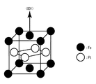
- FIG. 1 is a schematic cross-sectional view showing an embodiment of a perpendicular magnetic recording medium of the present invention. It is a schematic view showing a crystal structure of L1 0 type ordered alloys that may be used in the present invention.
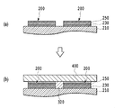
- (A) to (c) are schematic diagrams for explaining problems in the process of growth of granular magnetic material (FePt-C) of the magnetic recording layer.
- (A) to (b) are schematic diagrams for explaining the process of growth of granular magnetic material (FePt-B 4 C) of the magnetic recording layer.
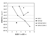
- FIG. 7 is a graph showing measurement results of the magnetic anisotropy constant (Ku) of the magnetic recording media of Examples 1 to 3 and 11 and Comparative Examples 1 to 5.
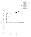
- FIG. 16 is a diagram comparing the results of Examples 7 to 10 and Comparative Example 7 with the results of Examples 11 to 12 and Comparative Example 8. It is the figure which added and further compared the result of Examples 13-17 with the result of FIG.
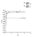
- FIG. 16 is a diagram in which the value of Mr / Ms is plotted against the total amount of boron (B) and carbon (C) in the second magnetic recording layers (the second layer) of Examples 13 to 17.
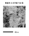
- FIG. 16 is a plan TEM image of the magnetic recording medium of Example 10;
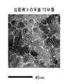
- FIG. 16 is a plan TEM image of the magnetic recording medium of Comparative Example 9;
- FIG. 16 is a diagram in which the value of Ku is plotted against the total film thickness of the magnetic recording layer for the magnetic recording media of Examples 1 to 3 and Examples 18 to 20.
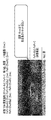
- Fig. 20 shows a vertical TEM image of a magnetic recording medium.
- FIG. 16 is a view showing a vertical TEM of the magnetic recording medium of Example 3;
- the magnetic recording medium of the present invention comprises at least a nonmagnetic substrate and a magnetic recording layer.
- FIG. 1 shows a more specific structural example of the magnetic recording medium of the present invention.
- the magnetic recording medium 100 of the present invention has a nonmagnetic substrate 20, an optional seed layer 40, a magnetic recording layer 60, and an optional protective layer 80.
- the magnetic recording layer 60 is composed of a plurality of layers including at least the first magnetic recording layer 62 and the second magnetic recording layer 64.
- FIG. 1 shows a two-layer structure of the first magnetic recording layer 62 and the second magnetic recording layer 64.
- the first magnetic recording layer is composed of a first magnetic crystal grain and a first nonmagnetic crystal grain boundary surrounding the first magnetic crystal grain
- the second magnetic recording layer is a second magnetic crystal grain, and this It is comprised from the 2nd nonmagnetic grain boundary surrounding the 2nd magnetic crystal grain.
- the seed layer 40 and the protective layer 80 are optional layers, but in the present invention, these layers are preferably provided.
- the magnetic recording medium of the present invention may further include an adhesion layer, a soft magnetic backing layer, a nonmagnetic underlayer, and the like between the nonmagnetic substrate 10 and the magnetic recording layer 40.
- a lubricating layer may be provided on the upper layer of the protective layer 80.
- the magnetic recording medium of the present invention is applicable to various perpendicular magnetic recording media including, for example, energy assisted magnetic recording media such as heat assisted type and microwave assisted type. Accordingly, the magnetic recording medium of the present invention can appropriately include layers necessary for various perpendicular magnetic recording media in addition to the above-described layers. For example, in a thermally assisted perpendicular magnetic recording medium, a heat sink layer or the like can be further included below the magnetic recording layer.
- the magnetic recording layer 60 is composed of a plurality of layers including at least the first magnetic recording layer 62 and the second magnetic recording layer 64.
- the construction of such a magnetic recording layer in the present invention will be described below.
- a magnetic recording layer of a magnetic crystal grain-nonmagnetic material which provides a granular structure comprising ordered alloy magnetic crystal grains and nonmagnetic crystal grain boundaries surrounding the ordered alloy magnetic crystal grains.
- ordered alloy has L1 0 type ordered alloys, such as iron platinum (FePt) system, an alloy such as cobalt platinum (CoPt) systems are known.
- the non-magnetic material for example, FePt- carbon (C) [hereinafter, FePt-C], FePt- SiO 2 or the like is known.
- FePt-C FePt- carbon
- FePt- SiO 2 FePt- SiO 2
- these materials are expected as materials capable of achieving high magnetic anisotropy, these materials have a problem of so-called secondary growth of magnetic crystal grains, which is accompanied by an increase in the film thickness of the magnetic recording layer. It has become clear from the studies of the present inventors that there is a problem that the granular structure can not be formed on the seed layer.
- the present invention solves such problems, provides a predetermined film thickness while maintaining high magnetic anisotropy, and provides a perpendicular magnetic recording medium sufficiently applicable to various methods including energy assist type.
- the purpose is
- L1 0 type ordered alloy - as a non-magnetic material, taking an example FePt-C and FePt-B 4 C, the a problem, the outline of the present invention will be described with reference to the drawings.
- Figure 2 is a crystal lattice diagram of L1 0 type FePt alloy. As shown in FIG. 2, L1 0 type FePt alloy is (001) has an orientation, having a structure in which Fe atoms and Pt atoms are alternately stacked.
- Figure 3 is a diagram showing a growth process when deposited on the seed layer 210 by sputtering an L1 0 type FePt-C material.
- the seed layer, and the MgO layer capable of forming an L1 0 type FePt magnetic crystal grains having a (001) orientation.
- FIG. 3A when the FePt—C material is deposited by sputtering, magnetic crystal grains 200 and nonmagnetic crystal grain boundaries 270 surrounding the crystal grains grow on the seed layer 210.
- the magnetic crystal grain 200 has a structure in which layers 230 of Fe atoms and layers 250 of Pt atoms are alternately stacked, as shown in FIG. 2, and crystals grow in a direction perpendicular to the seed layer 210. .
- FIG. 3 shows an example in which the layer 230 of Fe atoms is stacked on the seed layer 210, and the layer 250 of Pt atoms is stacked thereon.
- the layer 250 of Pt atoms may be stacked on the seed layer 210 and the layer 230 of Fe atoms may be formed thereon.
- deposition of FePt-C is advanced to further increase the film thickness, carbon wraps on the surface of the magnetic crystal grains, and carbon is deposited on the surfaces of the magnetic crystal grains (d in FIG. 3 (b), It impedes the growth of the magnetic crystal grains 200 (FIG.
- the height of magnetic grains from the seed layer exceeds 3 nm, for example, when the material of 75 vol% FePt-25 vol% C is used. It has been found by the present inventors that It was also found that the film thickness at which carbon wrap occurs varies depending on the diameter of the magnetic crystal grains, and as the diameter decreases, carbon wrap occurs at a thinner film thickness. That is, if it is attempted to reduce the size of magnetic crystal grains by increasing the amount of addition of carbon in order to improve the recording density, the film thickness at which good magnetic crystal grains can be formed will decrease. Therefore, it was found that it is difficult to increase the film thickness while maintaining high magnetic anisotropy in the FePt-C single layer.
- a magnetic recording medium having a granular structure formed of a magnetic material containing B 4 C as a nonmagnetic material is known (Patent Document 2).
- the magnetic recording medium actually produced in this document does not use an ordered alloy.
- FIG. 4A when a seed layer 210 made of MgO or the like is used, as shown in FIG. 4, formation of FePt magnetic crystal grains 200 is performed (FIG. 4A).
- Nonmagnetic crystal grain boundaries 320 surrounding magnetic crystal grains are not formed, or only slightly if formed (FIG. 4 (b)), magnetic crystal grains can not be separated from each other, and mixed state (400) It became clear in the study of the present inventors.
- B 4 C which is a nonmagnetic material
- B 4 C is also grown in the magnetic crystal grains as the FePt-B 4 C deposits, leading to the gradual destruction of the magnetic crystal grains. Such breakdown will reduce the magnetic anisotropy.
- the FePt—B 4 C material may not be able to be thickened in a single layer as well.
- SiC is also known as a nonmagnetic grain boundary segregation material, but in the same way as FePt-B 4 C, ordered alloy-SiC can not form a sufficient granular structure in a single layer. , It has been understood by the study of the present inventors.
- L1 0 type ordered alloy in advance as a template layer on the seed layer - by forming a carbon (C) (FePt-C), the L1 0 type ordered alloy - carbon (C) above carbide or regular metal - - rules metals L1 0 type in the carbon, one or more materials selected from boron and / or silicon (herein, carbides, boron (B) carbides or silicon (Si) Carbide, boron carbide (B 4 C) or silicon carbide (SiC), and carbon, and one or more materials selected from boron and / or silicon are also simply referred to as a carbon-containing nonmagnetic material) to form a granular structure
- the magnetic recording layer can be grown to a desired thickness. It has also been revealed that perpendicular magnetic recording media including such a magnetic recording layer have high magnetic anisotropy.
- the present invention has been made based on the above findings, and is capable of realizing a thick film of a magnetic recording layer while maintaining high magnetic anisotropy, with a magnetic recording layer having a granular structure.
- the nonmagnetic substrate 20 may be various substrates whose surface is smooth.
- the nonmagnetic substrate 20 can be formed using a material generally used for a magnetic recording medium.
- materials such as Al alloy plated with NiP, tempered glass, and crystallized glass can be used as the nonmagnetic substrate.
- an alloy material having excellent adhesion for example, Cr, CrTi, or Ta may be formed on the substrate as the adhesion layer.
- the optional soft magnetic backing layer is a layer having a function of concentrating the magnetic flux generated by the magnetic head on the magnetic recording layer during recording on the magnetic recording layer.
- the soft magnetic backing layer can be formed using a crystalline material such as FeTaC or Sendust (FeSiAl) alloy or an amorphous material containing a Co alloy such as CoZrNb, CoTaZr, or CoFeZrTa. In this case, it is necessary to select a material that does not cause a change in surface roughness due to crystallization at the formation temperature of the magnetic layer.
- the optimum value of the film thickness of the soft magnetic underlayer changes depending on the structure and characteristics of the magnetic head used for recording, but it is desirable that the film thickness be about 10 nm or more and 500 nm or less from the balance with productivity.
- a nonmagnetic underlayer which may optionally be provided, ensures adhesion between the soft magnetic backing layer and the seed layer 40, and allows the seed layer 40 to obtain a desired orientation.
- the nonmagnetic underlayer can be formed using Cr or an alloy containing Cr.
- the nonmagnetic underlayer may have a laminated structure including a plurality of layers of NiW, Ta, Cr, or an alloy containing Ta and / or Cr.
- the nonmagnetic underlayer has a thickness of 5 nm to 30 nm. It is desirable to have
- the function of the seed layer 40 is to control the crystal orientation and the like of the magnetic crystal grains of the magnetic recording layer 60 which is the upper layer. Also, it is desirable that the seed layer 40 be nonmagnetic.
- the seed layer 40 is a layer that is intended to be oriented crystals of the ordered alloy in the magnetic recording layer 60 (for example, in the case of such L1 0 type FePt alloy), for example (001). With such an orientation, perpendicular magnetic recording is possible.
- the material of the seed layer 40 is appropriately selected in accordance with the material of the magnetic crystal grains of the magnetic recording layer 60.
- the magnetic crystal grains in the magnetic recording layer 60 is formed by L1 0 type ordered alloy, preferably a material of the cubic, SrTiO 3, MgO, TiN, particularly preferably such CrN, and most preferably MgO It is.
- the seed layer 40 can also be formed using a mixture of the above oxides.
- the seed layer 40 can be formed by laminating a plurality of layers made of the above materials.
- the seed layer 40 desirably has a thickness of 1 nm to 60 nm, preferably 1 to 20 nm, from the viewpoint of improving the crystallinity of the magnetic crystal grains of the magnetic recording layer 60 and the productivity.
- the seed layer 40 can be formed using any method known in the art such as sputtering (including DC magnetron sputtering and RF sputtering), vacuum evaporation, and the like.
- the seed layer 40 is particularly preferably formed using MgO.
- the magnetic recording layer 60 includes at least two layers of a first magnetic recording layer 62 and a second magnetic recording layer 64.
- the first magnetic recording layer 62 has a granular structure including first magnetic crystal grains and first nonmagnetic crystal grain boundaries surrounding the first magnetic crystal grains
- the second magnetic recording layer includes second magnetic crystal grains and It has a granular structure including second nonmagnetic grain boundaries surrounding the second magnetic grain.
- the present invention is characterized in that the second magnetic recording layer has a granular structure in which nonmagnetic grain boundaries of the second magnetic recording layer are made of a material different from the first nonmagnetic grain boundaries of the first magnetic recording layer.
- the first magnetic recording layer 62 has a granular structure composed of first magnetic crystal grains containing an ordered alloy and first nonmagnetic crystal grain boundaries made of carbon.
- the second magnetic recording layer 64 is composed of a second magnetic crystal grain containing an ordered alloy, and a second nonmagnetic crystal grain boundary made of carbide, carbon, and at least one material selected from boron and silicon. It has a granular structure.
- the first nonmagnetic grain boundary is composed of carbon (C).
- the second nonmagnetic grain boundary is preferably carbide or one or more materials selected from carbon and boron and / or silicon, more preferably B 4 C, SiC, TiC, ZrC , Boron-carbon (B-C), etc., most preferably B 4 C, SiC or B-C.
- boron-carbon or “B-C” means that the nonmagnetic material of the second magnetic recording layer is composed of boron and carbon, but it is clear such as boron carbide. It is meant to include forms such as a mixture of boron (B) and carbon (C) as well as forms having a bond of boron (B) and carbon (C). B—C non-magnetic materials containing such multiple forms are referred to herein simply as “boron-carbon” or “B-C”.
- the ratio of the nonmagnetic material in the magnetic crystal grain-nonmagnetic material is preferably 20 vol% to 50 vol% of carbon in magnetic crystal grain-carbon, and more preferably 20 vol% to 40 vol%. preferable.
- the amount of carbon-containing nonmagnetic material in the ordered metal-carbon nonmagnetic material is preferably 20 vol% to 50 vol%, more preferably 20 vol% to 40 vol%, and 20 vol% to 30 vol%. It is further preferred that In order to increase the total film thickness of the magnetic recording layer, the above range is preferable.
- a ratio [B (B) of the second magnetic recording layer based on at% of boron (B) and carbon (C) is preferably 0.3 or more, and more preferably 0.4 or more.
- the first magnetic crystal grains of the first and second magnetic recording layer and the second magnetic crystal grains ordered alloy preferably, those containing an L1 0 ordered alloy.
- Fe, Co, and at least one element selected from Ni,, Pt, Pd, Au, Cu , L1 0 alloy preferably contains at least one element selected from Ir, and the like. More preferably, it ordered alloy is FePt, CoPt, FePd, and L1 0 type alloys comprised of a material selected from the group consisting of CoPd, and most preferably L1 0 type FePt alloy.
- a metal such as Ni, Mn, Cr, Cu, Ag, or Au may be added to the first and second magnetic crystal grains for the purpose of characteristic modulation of the magnetic crystal grains.
- Ni, Mn, and Cr magnetic interaction can be reduced and magnetic properties such as magnetic anisotropy and Curie temperature can be changed, so that desired magnetic properties can be adjusted.
- Cu, Ag, and Au the ordering temperature can be reduced, and the effect of improving the magnetic anisotropy can be obtained.
- the reversal magnetic field can be reduced due to the lowering of the Curie temperature, and the thermally assisted recording becomes easy. That is, when Mn is added to the magnetic crystal grains and combined with the carbon-containing nonmagnetic material, the temperature dependence of the reversal magnetic field changes largely near the Curie temperature, and the reversal magnetic field becomes less than the recording magnetic field generated by the magnetic head. . This enables thermally assisted recording at a temperature significantly lower than that of the prior art. In addition, the temperature gradient of the reversal magnetic field becomes large in this temperature range, and it becomes possible to improve the resolution of recording at the time of thermal assist recording.
- the degree of regularity S representing the degree of regular structure may be equal to or greater than a predetermined value.
- the degree of order S is measured by X-ray diffraction (XRD) of the magnetic recording medium, and is calculated by the ratio of the measured value to the theoretical value when completely ordered. For example, in the case of L1 0 type ordered alloy, first calculates the (001) and (002) integrated intensity of the peak derived from the ordered alloy.
- the value (IN1) of the ratio of the integrated intensity of the (002) peak to the integrated intensity of the measured (001) peak (IN 1) and the integrated intensity of the (001) peak theoretically calculated when completely ordered Calculate the value (IN2) of the ratio of the integrated intensity of the (002) peak to.
- the degree of order S can be obtained by dividing the value (IN1) obtained by the above measurement by the value (IN2) calculated theoretically. If the degree of order S obtained in this manner is 0.5 or more, it has a magnetic anisotropy constant Ku practical for a magnetic recording medium.
- the magnetic recording layer 60 may have a structure in which more magnetic recording layers are stacked.
- the magnetic recording layer 60 may have a structure in which a plurality of the first magnetic recording layer and the second magnetic recording layer described above are stacked, and the first magnetic recording layer and the second magnetic recording layer may be formed.
- these magnetic recording layers may have a structure in which magnetic recording layers made of materials having different compositions or constituent elements are further stacked.
- the magnetic recording layer 60 has a structure in which different ordered metal-carbon containing nonmagnetic materials are alternately laminated, such as a structure in which a first magnetic recording layer, a second magnetic recording layer, and a first magnetic recording layer are sequentially laminated. May be included.
- the magnetic recording layer 60 may be provided with an additional layer such as a CAP layer.
- the first magnetic crystal grains and the second magnetic crystal grains can be made of different materials.
- the magnetic recording layer 60 at least includes the first magnetic recording layer 62 and the second magnetic recording layer 64 having the above-described configuration.
- the first nonmagnetic material surrounding the first nonmagnetic crystal grains is carbon (C).
- the second magnetic recording layer 64 is formed on the first nonmagnetic material by using a granular magnetic material containing a carbon-containing nonmagnetic material which is a second nonmagnetic material, thereby forming the first magnetic recording layer.
- the second magnetic recording layer 64 having a granular structure in accordance with the granular structure can be efficiently formed.
- the first magnetic recording layer is formed in advance as a magnetic recording layer made of FePt-C, and FePt-B 4 C, FePt-B- is formed on the first magnetic recording layer 62.
- C forming a second magnetic recording layer 64 containing an ordered alloy to which a carbon-containing nonmagnetic material such as FePt-SiC is added, and forming a plurality of these magnetic recording layers alternately to achieve high magnetic properties Thickening of the entire magnetic recording layer 60 was realized while maintaining the anisotropy.
- the film thickness of the first magnetic recording layer is 4 nm or less, preferably 2 to 4 nm. Above 4 nm, growth inhibition and secondary growth of ordered alloys occur. From the viewpoint of maintaining high magnetic anisotropy, the thickness of the second magnetic recording layer is preferably 3 to 7 nm.
- the thickness of the magnetic recording layer 60 is not particularly limited. However, from the viewpoint of achieving both high productivity and high recording density, the magnetic recording layer 60 desirably has a thickness of at least 5 nm or more, preferably 8 nm or more.
- the preferred film thickness as the magnetic recording layer 60 is 6 to 16 nm, more preferably 8 to 11 nm.
- the magnetic recording medium of the present invention at least 6.5E + 06erg / cm 3 or more is preferable as the value of the anisotropy constant (Ku), more preferably having 1.0E + 07erg / cm 3 or more, It is even more preferable to have 1.2E + 07 erg / cm 3 or more.
- the value of the residual magnetization (Mr) divided by the saturation magnetization (Ms) preferably exceeds 0.70, and more preferably is 0.75 or more. .
- Mr / Ms the value of the residual magnetization (Mr) divided by the saturation magnetization (Ms)
- a Tc control magnetic layer having a Curie temperature Tc different from that of the magnetic recording layer can be further disposed.
- the Curie temperature of the Tc control magnetic layer is set lower than the Curie temperature of the magnetic recording layer. If the recording temperature is set to the middle between the two Curie temperatures, the magnetization of the Tc control magnetic layer disappears during recording, and the magnetic field necessary to reverse the recording is reduced. In this manner, the magnetic field generated at the time of recording required for the magnetic recording head can be reduced, and good magnetic recording performance can be realized.
- the arrangement of the Tc control magnetic layer may be either above or below the magnetic recording layer.
- the Tc control magnetic layer preferably has a granular structure. It is particularly preferable to arrange the magnetic crystal grains of the magnetic recording layer and the Tc control magnetic layer substantially at the same position. By setting the positions approximately at the same position, the performance such as the signal to noise ratio (SNR) can be improved.
- SNR signal to noise ratio
- the magnetic crystal grains constituting the Tc control magnetic layer are preferably made of a material containing at least one of Co or Fe, and further an element selected from Pt, Pd, Ni, Mn, Cr, Cu, Ag, or Au It is more preferable to include at least one of For example, a CoCr-based alloy, a CoCrPt-based alloy, an FePt-based alloy, an FePd-based alloy, or the like can be used.
- the crystal structure of the magnetic crystal grains can be the L1 0 type, L1 1 type, L1 ordered structure of type 2, etc., hcp structure (hexagonal close-packed structure), fcc structure (face-centered cubic structure) and the like.
- the above-mentioned carbon-containing nonmagnetic material an oxide such as SiO 2 or TiO 2 , a nitride such as SiN or TiN, C, B or the like is used. be able to.
- an exchange coupling control layer between the magnetic recording layer and the Tc control magnetic layer.
- the exchange coupling control layer a layer having magnetic properties or a nonmagnetic layer can be selected depending on the desired exchange coupling. It is preferable to use a nonmagnetic layer in order to enhance the reduction effect of the switching magnetic field at the recording temperature.
- a Ku control magnetic layer having a uniaxial crystal magnetic anisotropy constant Ku different from the magnetic recording layer can be disposed.
- the arrangement of the Ku control magnetic layer may be either above or below the magnetic recording layer.
- the Ku control magnetic layer preferably has a granular structure. It is particularly preferable to arrange the magnetic crystal grains of the magnetic recording layer and the Ku control magnetic layer substantially at the same position. By setting the positions approximately at the same position, the performance such as the signal to noise ratio (SNR) can be improved.
- SNR signal to noise ratio
- the magnetic crystal grains constituting the Ku control magnetic layer are preferably made of a material containing at least one of Co or Fe, and further an element selected from Pt, Pd, Ni, Mn, Cr, Cu, Ag, or Au. It is more preferable to include at least one.
- a CoCr-based alloy, a CoCrPt-based alloy, an FePt-based alloy, an FePd-based alloy, or the like can be used.
- the crystal structure of the magnetic crystal grains can be the L1 0 type, L1 1 type, L1 ordered structure of type 2, etc., hcp structure (hexagonal close-packed structure), fcc structure (face-centered cubic structure) and the like.
- the above-mentioned carbon containing nonmagnetic material an oxide such as SiO 2 or TiO 2 , a nitride such as SiN or TiN, C, B or the like is used. be able to.
- an exchange coupling control layer between the magnetic recording layer and the Ku control magnetic layer.
- the thermal stability can be adjusted by adjusting the magnetic exchange coupling during recording and storage.
- the exchange coupling control layer a layer having magnetic properties or a nonmagnetic layer can be selected depending on the desired exchange coupling. It is preferable to use a nonmagnetic layer in order to enhance the effect of improving the thermal stability at the recording storage temperature.
- the optional protective layer 80 is a layer for protecting each component layer below the magnetic recording layer 60 below.
- the protective layer 80 in the present invention can be formed using a material conventionally used in the field of magnetic recording media, such as a material mainly composed of carbon.
- the protective layer 80 may be a single layer or may have a laminated structure.
- the protective layer 80 having a laminated structure may have, for example, a laminated structure of two carbon-based materials having different properties, a laminated structure of a metal and a carbon-based material, or a laminated structure of a metal oxide film and a carbon-based material Good.
- the thickness of the protective layer is preferably 10 nm or less, typically.
- the optional lubricating layer can be formed using a liquid lubricant such as PFPE (perfluoropolyether).
- PFPE perfluoropolyether
- the film thickness of the liquid lubricant layer is preferably set to a film thickness that can exhibit the function of the liquid lubricant layer in consideration of the film quality and the like of the protective layer.
- a nonmagnetic underlayer is formed on the nonmagnetic substrate 20, if necessary.
- the seed layer 40 is formed.
- Each of these layers can be formed by a sputtering method (including a DC magnetron sputtering method, an RF magnetron sputtering method, and the like), a vacuum evaporation method, and the like.
- the adhesion layer which consists of materials, such as metals, such as Ta and Cr, or these metal type alloys, can be formed on a nonmagnetic substrate as needed.
- the magnetic recording layer 60 is formed.
- the first magnetic recording layer 62 is formed by a sputtering method using a metal and an alloy target containing carbon constituting an ordered alloy, a vacuum evaporation method, or the like.
- the second magnetic recording layer 64 is formed on the first magnetic recording layer 62.
- the second magnetic recording layer 64 can be formed by sputtering or vacuum evaporation using an alloy target containing a metal forming the ordered alloy and a desired carbon-containing nonmagnetic material.
- the temperature of the nonmagnetic substrate 20 which is a film formation substrate or the nonmagnetic substrate 20 on which an appropriate constitution layer is formed is It is desirable to heat to
- the present invention as a method of forming the first magnetic recording layer 62 and the second magnetic recording layer, materials including ordered alloys (for example, Fe, Pt) other than sputtering using an alloy target as described above, and A co-sputtering method in which C, C or their alloys are separately sputtered can also be employed.
- ordered alloys for example, Fe, Pt
- a co-sputtering method in which C, C or their alloys are separately sputtered can also be employed.
- the protective layer 80 is formed on the magnetic recording layer 60.
- the protective layer 80 can be formed using the above-mentioned materials, for example, formed using any method known in the art such as sputtering (including DC magnetron sputtering), vacuum evaporation, and the like. can do.
- the optional liquid lubricant layer can be formed using materials conventionally used in the field of magnetic recording media (for example, perfluoropolyether lubricants and the like).
- the liquid lubricant layer can be formed, for example, using a coating method such as dip coating method or spin coating method.
- Examples 1 to 17 and Comparative Examples 1 to 9 (I) (Examples 1 to 3) A perpendicular magnetic recording medium was prepared having a nonmagnetic substrate, a Ta adhesion layer, a Cr underlayer, a MgO seed layer, an ordered alloy (FePt-based) magnetic recording layer, and a carbon (C) protective layer sequentially provided thereon.
- Examples 1 to 3 show an example in which FePt-C is used for the first magnetic recording layer and FePt-B 4 C is used for the second magnetic recording layer.
- a chemically strengthened glass substrate (N-10 glass substrate manufactured by Hoya Corporation) was prepared as a nonmagnetic substrate.
- the nonmagnetic substrate was introduced into the sputtering apparatus.
- the film formation from the Ta adhesion layer to the C protective layer was performed by an in-line type film formation apparatus without releasing to the atmosphere.
- the Ta adhesion layer was formed to a film thickness of 5 nm by DC magnetron sputtering in an Ar atmosphere using a pure Ta target.
- a Cr underlayer was formed to a film thickness of 20 nm by DC magnetron sputtering in an Ar atmosphere using a pure Cr target.
- the base was heated to 300 ° C., and a MgO target was used to form a 5 nm-thick seed layer by RF sputtering.
- the MgO layer which is a seed layer, was deposited at an RF power of 200 W in an Ar gas atmosphere with a degree of vacuum of 0.1 Pa.
- the first magnetic recording layer is a FePt-C layer.
- the substrate on which each of the above layers was formed was heated to 400 ° C., and FePt and C were prepared such that the composition at the time of film formation is FePt (vol%)-C (vol%) described in Table 1.
- a first magnetic recording layer having a thickness shown in Table 1 was formed by DC magnetron sputtering using a target including The first magnetic recording layer (FeP—C layer) was formed at a DC power of 100 W in an Ar gas atmosphere with a degree of vacuum of 1.0 Pa.
- the second magnetic recording layer of this example is a FePt-B 4 C layer.
- the film formation was performed as follows. FePt (vol%)-B 4 C (vol%) described in Table 1 in a state where the substrate on which the first magnetic recording layer is formed as described above is heated to 400 ° C.
- a second magnetic recording layer having a thickness shown in Table 1 was formed by DC magnetron sputtering using a target containing boron and boron.
- the second magnetic recording layer (FeP—B 4 C layer) was formed at a DC power of 100 W in an Ar gas atmosphere with a degree of vacuum of 1.0 Pa.
- a carbon protective layer with a film thickness of 3 nm was formed by DC magnetron sputtering using a carbon target in an Ar gas atmosphere, to obtain a magnetic recording medium.
- Examples 4 to 6 A perpendicular magnetic recording medium was prepared having a nonmagnetic substrate, a Ta adhesion layer, a Cr underlayer, a MgO seed layer, an ordered alloy (FePt-based) magnetic recording layer, and a carbon (C) protective layer sequentially provided thereon.
- Examples 4 to 6 show examples in which FePt-C is used for the first magnetic recording layer and FePt-SiC is used for the second magnetic recording layer.
- a chemically strengthened glass substrate (N-10 glass substrate manufactured by Hoya Corporation) was prepared as a nonmagnetic substrate.
- the nonmagnetic substrate was introduced into the sputtering apparatus.
- the film formation from the Ta adhesion layer to the C protective layer was performed by an in-line type film formation apparatus without releasing to the atmosphere.
- the Ta adhesion layer was formed to a film thickness of 5 nm by DC magnetron sputtering in an Ar atmosphere using a pure Ta target.
- a Cr underlayer was formed to a film thickness of 20 nm by DC magnetron sputtering in an Ar atmosphere using a pure Cr target.
- the base was heated to 300 ° C., and a MgO target was used to form a 5 nm-thick seed layer by RF sputtering.
- the MgO layer which is a seed layer, was deposited at an RF power of 200 W in an Ar gas atmosphere with a degree of vacuum of 0.1 Pa.
- the first magnetic recording layer is a FePt-C layer.
- the substrate on which each layer described above was formed was heated to 400 ° C., and FePt and C prepared so that the composition at the time of film formation was FePt (vol%)-C (vol%) described in Table 2
- a first magnetic recording layer of the thickness shown in Table 2 was formed by DC magnetron sputtering using a target including The first magnetic recording layer (FeP—C layer) was formed at a DC power of 100 W in an Ar gas atmosphere with a degree of vacuum of 1.0 Pa.
- the second magnetic recording layer of this example is a FePt—SiC layer.
- the film formation was performed as follows. FePt and SiC prepared to be FePt (vol%)-SiC (vol%) described in Table 2 in a state where the substrate on which the first magnetic recording layer is formed as described above is heated to 400 ° C.
- the second magnetic recording layer having the thickness shown in Table 2 was formed by DC magnetron sputtering using a target including
- the second magnetic recording layer (FeP—SiC layer) was formed at a DC power of 100 W in an Ar gas atmosphere with a degree of vacuum of 1.0 Pa.
- a carbon protective layer with a film thickness of 3 nm was formed by DC magnetron sputtering using a carbon target in an Ar gas atmosphere, to obtain a magnetic recording medium.
- Example 7 to 17 A perpendicular magnetic recording medium was prepared having a nonmagnetic substrate, a Ta adhesion layer, a Cr underlayer, a MgO seed layer, an ordered alloy (FePt-based) magnetic recording layer, and a carbon (C) protective layer sequentially provided thereon.
- Examples 7 to 17 show an example in which FePt-C is used for the first magnetic recording layer and FePt-BC is used for the second magnetic recording layer.
- the content of carbon (C) in the first magnetic recording layer is fixed at 40 vol% or 25 vol%, and the content ratio of boron (B) and carbon (C) in the second magnetic recording layer is changed. This is an example in which the magnetic properties are evaluated.
- the carbon (C) content of the first magnetic recording layer is fixed at 40 vol%, and the total amount of B-C of the second magnetic recording layer is fixed at 25 vol%, respectively. It is an example which changed the content rate of boron (B) and carbon (C).
- the carbon (C) content of the first magnetic recording layer is fixed to 25 vol%, and the total amount of B—C of the second magnetic recording layer is fixed to 25 vol%, and the boron of the second magnetic recording layer is fixed. It is an example which changed the content rate of (B) and carbon (C).
- the C content of the first magnetic recording layer is fixed at 40 vol%, and the total B-C content of the second magnetic recording layer is changed.
- a chemically strengthened glass substrate (N-10 glass substrate manufactured by Hoya Corporation) was prepared as a nonmagnetic substrate.
- the nonmagnetic substrate was introduced into the sputtering apparatus.
- the film formation from the Ta adhesion layer to the C protective layer was performed by an in-line type film formation apparatus without releasing to the atmosphere.
- the Ta adhesion layer was formed to a film thickness of 5 nm by DC magnetron sputtering in an Ar atmosphere using a pure Ta target.
- a Cr underlayer was formed to a film thickness of 20 nm by DC magnetron sputtering in an Ar atmosphere using a pure Cr target.
- the base was heated to 300 ° C., and a MgO target was used to form a 5 nm-thick seed layer by RF sputtering.
- the MgO layer which is a seed layer, was deposited at an RF power of 200 W in an Ar gas atmosphere with a degree of vacuum of 0.1 Pa.
- the first magnetic recording layer is a FePt-C layer.
- the substrate on which each layer described above was formed was heated to 400 ° C., and FePt and C prepared so that the composition at the time of film formation was FePt (vol%)-C (vol%) described in Table 3
- a first magnetic recording layer of the thickness shown in Table 3 was formed by DC magnetron sputtering using a target including The first magnetic recording layer (FeP—C layer) was formed at a DC power of 100 W in an Ar gas atmosphere with a degree of vacuum of 1.0 Pa.
- the second magnetic recording layer of this example is a FePt--B--C layer.
- the film formation was performed as follows. FePt prepared as FePt (vol%)-B-C (vol%) described in Table 3 in a state where the substrate on which the first magnetic recording layer is deposited as described above is heated to 400 ° C.
- a second magnetic recording layer having a thickness shown in Table 3 was formed by DC magnetron sputtering using a target containing boron (B) and carbon (C).
- the second magnetic recording layer (FeP-B-C layer) was formed with DC power of 100 W in an Ar gas atmosphere with a degree of vacuum of 1.0 Pa.
- each magnetic recording layer of each comparative example is a film formation of the first magnetic recording layer of Examples 1 to 6 for "FePt-C layer".
- the film is formed under the conditions, and the film of “FePt—B 4 C layer” is formed under the film forming condition of the second magnetic recording layer of Examples 1 to 3.
- the “FePt—SiC layer” is The film was formed under the film forming conditions of the second magnetic recording layer 6.
- a perpendicular magnetic recording medium was prepared having a nonmagnetic substrate, a Ta adhesion layer, a Cr underlayer, a MgO seed layer, an ordered alloy (FePt-based) magnetic recording layer, and a carbon (C) protective layer sequentially provided thereon.
- Comparative Examples 7 and 8 are examples in which FePt-C is used for the first and second magnetic recording layers.
- a chemically strengthened glass substrate (N-10 glass substrate manufactured by Hoya Corporation) was prepared as a nonmagnetic substrate.
- the nonmagnetic substrate was introduced into the sputtering apparatus.
- the film formation from the Ta adhesion layer to the C protective layer was performed by an in-line type film formation apparatus without releasing to the atmosphere.
- the Ta adhesion layer was formed to a film thickness of 5 nm by DC magnetron sputtering in an Ar atmosphere using a pure Ta target.
- a Cr underlayer was formed to a film thickness of 20 nm by DC magnetron sputtering in an Ar atmosphere using a pure Cr target.
- the base was heated to 300 ° C., and a MgO target was used to form a 5 nm-thick seed layer by RF sputtering.
- the MgO layer which is a seed layer, was deposited at an RF power of 200 W in an Ar gas atmosphere with a degree of vacuum of 0.1 Pa.
- the first magnetic recording layer is a FePt-C layer.
- the substrate on which each layer described above was formed was heated to 400 ° C., and FePt and C prepared so that the composition at the time of film formation was FePt (vol%)-C (vol%) described in Table 5
- the first magnetic recording layer of the thickness shown in Table 5 was formed by DC magnetron sputtering using a target including The first magnetic recording layer (FeP—C layer) was formed at a DC power of 100 W in an Ar gas atmosphere with a degree of vacuum of 1.0 Pa.
- the second magnetic recording layer of this comparative example is a FePt-C layer.
- the film formation was performed as follows. FePt prepared so as to be FePt (vol%)-C (vol%) described in Table 5 in a state where the substrate on which the first magnetic recording layer is formed as described above is heated to 400 ° C.
- the second magnetic recording layer having the thickness shown in Table 5 was formed by DC magnetron sputtering using a target containing carbon.
- the second magnetic recording layer (FePt—C layer) was formed at a DC power of 100 W in an Ar gas atmosphere with a degree of vacuum of 1.0 Pa.
- the present comparative example is an example in which the second magnetic recording layer is FePt—SiO 2 in a two -layer magnetic recording medium.
- the film forming conditions of this comparative example are as follows: using the target containing FePt and SiO 2 prepared so as to be FePt (75 vol%)-SiO 2 (25 vol%) in forming the second magnetic recording layer; The same as Comparative Examples 7 to 8 except that the film thicknesses of the magnetic recording layer and the second magnetic recording layer were 3 nm (total film thickness 6 nm), respectively.
- the magnetic recording medium obtained in this comparative example had a Ku of 1.80E + 07 erg / cm 3 and an Mr / Ms value of 0.95.
- the coercivity (Hc) and the ⁇ value (the inclination of the magnetization curve in the vicinity of the coercivity) of the MH hysteresis loop were determined.
- a specific measurement method evaluates the MH hysteresis loop using a PPMS device, and determines ⁇ from the slope (dM / dH) near the coercivity (Hc) from saturation magnetization (Ms) obtained using VSM
- (alpha) made 0.6 or more and 2.5 or less the favorable range.
- FIG. 5 compares the results of Examples 1 to 3 with Comparative Examples 1 to 5
- FIG. 6 compares the results of Examples 4 to 6 with Comparative Examples 1 to 4 and 6.
- FIG. 5 the result of Example 11 to be described later is shown as “BC / C” (black circle) as a reference.
- the thickness is thicker than that of a magnetic recording medium including a magnetic recording layer of FePt-C single layer. Even if the film was thickened, the Ku value could be increased as a whole.
- the coercivity (Hc) and the ⁇ value of the hysteresis loop were also better than in the comparative example.
- the characteristics of the nonmagnetic material in the ordered alloy-nonmagnetic material are considered as follows.
- Carbon (C) diffuses rapidly in the FePt crystal and has good dischargeability from within the FePt crystal grains. However, when the film thickness is 4 nm, it also diffuses to the upper surface of the FePt crystal grains (columnar growth) and causes secondary growth of the FePt crystal.
- B 4 C has the slowest diffusion and tends to remain in FePt grains, but does not diffuse to the upper surface of FePt grains (columnar growth). Therefore, a large Ku can not be obtained, but there is no decrease in Ku even if it is thickened. B 4 C is relatively difficult to form a granular structure on the MgO seed layer.
- SiC is considered to be an intermediate property of carbon (C) and B 4 C, and emission to nonmagnetic grain boundaries is considered to progress to some extent with the growth of the magnetic recording layer.
- the magnetic recording medium including the magnetic recording layer of FePt-C single layer in which the film thickness of FePt-C magnetic recording layer is 2 nm and the film thickness of FePt-SiC magnetic recording layer is 3 nm. It is possible to reduce the diffusion of SiC to the surface of the columnar growth of FePt crystal grains, and to relatively suppress the secondary growth of FePt crystal grains accompanying the increase of the thickness of the magnetic recording layer. As a result, a very high Ku can be obtained in a single layer up to the above film thickness. However, as the film thickness of the FePt—SiC layer increases, SiC also diffuses onto the columnar growth surface of FePt crystal grains, which has the possibility of causing secondary growth.
- Mr / Ms is low, it means that there are particles that can not keep the direction of magnetization in the direction of magnetization when there is no magnetic field applied during magnetic recording, and such in magnetic recording. Particles are undesirable sources of noise in the reproduced signal.
- the value of Mr / Ms is preferably more than 0.70.
- FIGS. 7-8 The values of Mr / Ms are summarized in FIGS. 7-8.
- FIG. 7 compares the results of Examples 7 to 10 and Comparative Example 7 with the results of Examples 11 to 12 and Comparative Example 8, and
- FIG. 8 further shows Example 13 to the results of FIG. 17 results are added and compared.
- FIG. 9 is a plot of Mr / Ms values with respect to the total amount of boron (B) and carbon (C) in the second magnetic recording layers (the second layer) of Examples 13-17.
- the ratio (B / C ratio) of boron (B) and carbon (C) in the second magnetic recording layer is preferably 0.3 or more, and more preferably 0.4 or more. You see ( Figure 7). Furthermore, also from the results of Examples 13 to 17 (these are investigations of the B-C content of the second magnetic recording layer over a wider range than in Examples 7 to 12), the B / C ratio is 0. 3 or more are preferable and 0.4 or more are more preferable (FIG. 8).
- the content of the nonmagnetic material in the ordered metal-nonmagnetic material is preferably 20 vol% to 40 vol%, and more preferably 20 vol% to 30 vol%.
- Example 11 As shown in FIG. 5 together with Examples 1 to 6 in Example 11, the same excellent magnetic characteristics as in Examples 1 to 6 were realized even when FePt-B-C was used. .
- Example 10 and Comparative Example 9 Results of Example 10 and Comparative Example 9
- the magnetic recording media of Example 10 and Comparative Example 9 were measured by transmission electron microscopy (TEM). A planar TEM was measured. The results are shown in FIGS. 10A and 10B.
- TEM transmission electron microscopy
- Examples 18 to 20 are examples in which the magnetic recording layer is composed of a plurality of three or more layers.
- a perpendicular magnetic recording medium was prepared having a nonmagnetic substrate, a Ta adhesion layer, a Cr underlayer, a MgO seed layer, an ordered alloy (FePt-based) magnetic recording layer, and a carbon (C) protective layer sequentially provided thereon.
- FePt-C was used for the odd-numbered magnetic recording layers
- FePt-B 4 C was used for the even-numbered magnetic recording layers (the detailed layer configuration and the film thickness of each layer are shown in Table 8). ).
- a chemically strengthened glass substrate (N-10 glass substrate manufactured by Hoya Corporation) was prepared as a nonmagnetic substrate.
- the nonmagnetic substrate was introduced into the sputtering apparatus.
- the film formation from the Ta adhesion layer to the C protective layer was performed by an in-line type film formation apparatus without releasing to the atmosphere.
- the Ta adhesion layer was formed to a film thickness of 5 nm by DC magnetron sputtering in an Ar atmosphere using a pure Ta target.
- a Cr underlayer was formed to a film thickness of 20 nm by DC magnetron sputtering in an Ar atmosphere using a pure Cr target.
- the base was heated to 300 ° C., and a MgO target was used to form a 5 nm-thick seed layer by RF sputtering.
- the MgO layer which is a seed layer, was deposited at an RF power of 200 W in an Ar gas atmosphere with a degree of vacuum of 0.1 Pa.
- the first magnetic recording layer is a FePt-C layer.
- the substrate on which each of the above layers was formed was heated to 400 ° C., and FePt and C were prepared such that the composition at the time of film formation is FePt (vol%)-C (vol%) described in Table 1.
- a first magnetic recording layer having a thickness shown in Table 8 was formed by DC magnetron sputtering using a target including The first magnetic recording layer (FeP—C layer) was formed at a DC power of 100 W in an Ar gas atmosphere with a degree of vacuum of 1.0 Pa.
- the second magnetic recording layer of this example is a FePt-B 4 C layer.
- the film formation was performed as follows. FePt (vol%)-B 4 C (vol%) described in Table 8 in a state where the substrate on which the first magnetic recording layer is deposited as described above is heated to 400 ° C.
- a second magnetic recording layer having a thickness shown in Table 1 was formed by DC magnetron sputtering using a target containing boron and boron.
- the second magnetic recording layer (FeP—B 4 C layer) was formed at a DC power of 100 W in an Ar gas atmosphere with a degree of vacuum of 1.0 Pa.
- the procedure of the first magnetic recording layer and the second magnetic recording layer was repeated as many times as necessary to form a magnetic recording layer having a desired number of layers.
- a carbon protective layer with a film thickness of 3 nm was formed by DC magnetron sputtering using a carbon target in an Ar gas atmosphere, to obtain a magnetic recording medium.
- the coercivity (Hc) and the ⁇ value of the hysteresis loop were determined.
- the evaluation method is the same as in Examples 1 to 6.
- Table 8 also shows the results of Examples 1 to 3 as a reference.
- FIG. 11 is a plot of the Ku value against the total film thickness of the magnetic recording layer.
- the film thickness can be further increased while maintaining the ⁇ value of Ku, Hc and hysteresis loop.
- Example 3 of the two-layer structure the growth inhibition of the ordered alloy occurs at a film thickness of about 7 nm, but in Example 20 having more layers, the film thickness is up to about 10 nm. This did not happen.
- FePt-C is used as the first magnetic recording layer and combined with this as the second magnetic recording layer as one embodiment of the present invention.
- a magnetic recording layer having a granular structure of a magnetic crystal grain-carbon containing nonmagnetic material including the ordered alloy used in the above embodiment thickening the entire magnetic recording layer while maintaining high magnetic anisotropy
- high magnetic anisotropy is maintained by alternately providing a plurality of layers of FePt-C layer and magnetic grain-carbon-containing nonmagnetic material containing ordered alloy. A further increase in the film thickness of the entire magnetic recording layer could be realized.
- the magnetic recording medium of the present invention can be used for a magnetic recording apparatus including a perpendicular magnetic recording medium, including an energy assisted magnetic recording medium such as a thermal assist type or microwave assisted type.
Landscapes
- Magnetic Record Carriers (AREA)
Abstract
本発明は、非磁性基板及び磁気記録層を少なくとも含む垂直磁気記録媒体であり、前記磁気記録層は、少なくとも第1磁気記録層及び第2磁気記録層を含む複数層からなり、前記第1磁気記録層は、第1磁性結晶粒と、前記第1磁性結晶粒を取り囲む第1非磁性結晶粒界とを含むグラニュラー構造を有し、前記第1磁性結晶粒は規則合金を含み、前記第1非磁性結晶粒界は炭素からなり、前記第2磁気記録層は、第2磁性結晶粒と、前記第2磁性結晶粒を取り囲む第2非磁性結晶粒界とを含むグラニュラー構造を有し、前記第2磁性結晶粒は規則合金を含み、前記第2非磁性結晶粒界は、炭素含有非磁性材料からなるものである。
Description
本発明は、垂直磁気記録媒体に関する。特に、本発明は、グラニュラー磁性層を含む垂直磁気記録媒体において、高い磁気異方性を維持しながら該磁性層を厚膜化したものに関する。
近年、磁気記録の高密度化の要請が著しい。磁気記録の高密度化を実現する技術として、垂直磁気記録方式が採用されている。この方式に基づいた垂直磁気記録媒体は、非磁性基板と、硬質磁性材料を含む磁気記録層を少なくとも含む。垂直磁気記録媒体は、前記要素に加え、軟磁性材料から形成され、磁気ヘッドが発生する磁束を磁気記録層に集中させる役割を担う軟磁性裏打ち層、磁気記録層の硬質磁性材料を目的の方向に配向させるための下地層、磁気記録層の表面を保護する保護膜などを、任意選択的に、更に含んでいてもよい。
垂直磁気記録媒体の磁気記録層を形成するための材料として、グラニュラー磁性材料が用いられる。このグラニュラー磁性材料は、磁性材料と非磁性材料から構成され、磁性結晶粒と、磁性結晶粒の周囲を取り囲むように偏析した非磁性材料から構成されるグラニュラー構造をもたらす。磁性材料は、近年では例えば規則合金が注目されており、非磁性材料には、炭素系、酸化物系、窒化物系等が知られている(例えば、特許文献1等を参照)。
垂直磁気記録媒体では、グラニュラー磁性材料として各種材料が提案されているが、磁性結晶粒としての規則合金と、非磁性材料との組み合わせによっては、磁気記録層の膜厚が大きくなると、非磁性材料が磁性結晶粒の粒界のみならず磁性結晶粒の表面にも析出し、磁性結晶粒の成長を妨げるという現象が起こることがある(非特許文献1参照)。このような表面への析出が起こった後に、更に磁気記録層の膜厚を厚くしていくと、磁性結晶粒の表面に析出した非磁性材料上に磁性結晶粒子が成長する、所謂二次成長が起こる。このような二次成長は、結果的に、垂直磁気記録媒体の磁気異方性を低下させることになっていた。
このため、グラニュラー磁性材料に含まれる非磁性材料についても種々の材料が検討されている。例えば、特許文献2は、B4Cを非磁性材料として用いた磁気記録層を含む垂直磁気記録媒体を開示している。特許文献2は、高い熱安定性、高い磁気異方性定数(Ku)等を実現できること、及びDCスパッタリング法により成膜が行えることを報告している。しかし、特許文献2は、規則合金と組み合わせてB4Cを用いることの言及はない。
特許文献3は、L10型の結晶構造を有する規則合金にSiO2等の酸化物を非磁性材料として添加したグラニュラー磁性材料を第1の磁性層に用い、このような酸化物を含まない連続層(CAP層)としての第2の磁性層を用いた二層構造の磁性層を有する熱アシスト磁気記録媒体を開示している。特許文献3の発明では、第1の磁性層中の非磁性材料の含有率が、前記基板側から前記第2の磁性層側に向かって減少していることを特徴としており、このような構成にすることによって、過剰な非磁性材料が規則合金の結晶粒の上部に析出し、結晶粒の成長が垂直方向に分断されることを防いでいる。また、これによって、粒径が微細で、且つ、基板面に対して垂直な方向に連続的に成長した規則合金の結晶粒を実現している。
また、グラニュラー磁性材料を含む複数の磁性層からなり、これらの磁性層において非磁性材料の濃度が異なっている磁気記録媒体も知られている。
例えば、特許文献4は、基板上に基板温度制御層を形成する工程と、基板温度制御層上に下地層を形成する工程と、下地層上に磁気記録層を形成する工程とを有し、磁気記録層を形成する工程では、基板を加熱チャンバで加熱する第1工程と、C、Si酸化物からなる群から選ばれた少なくとも一種の非磁性材料を添加したFePtを主とする合金からなる磁気記録層を製膜チャンバで製膜する第2工程とからなる磁性層積層工程をN回(N≧2)繰り返して垂直磁気記録媒体を製造する方法を開示している。この製造方法により、磁気記録層を製膜する間の基板温度の変化を小さくし、結晶粒径を小さくしている。また、特許文献4では、磁気記録層に添加する非磁性材料の含有量について、基板側の添加量を多くしている。
また、特許文献5は、Fe及びPtを主原料とする磁性合金と、カーボン、酸化物、窒化物から選ばれる少なくとも一種の非磁性材料を含有する複数の磁性層により構成された磁気記録層を有する磁気記録媒体を開示している。特許文献5の磁気記録層では、第一の磁性層よりも表面側に位置する第二の磁性層が、第一の磁性層(FePt合金と前記非磁性材料とで構成されている)のFePt磁性合金粒子の直径よりも微細な状態で混ざり合った均質な構造を有する。また、特許文献5では、第一の磁性層は、第二の磁性層と比較して、非磁性材料であるカーボンの含有量が多く、それ以外の酸化物及び窒化物の含有量が少ないことを特徴としている。
Appl. Phys. Express, 101301, 2008
富士時報 vol.83,No.4 2010年,257~260頁
R. F. Penoyer, Rev. Sci. Instr. 30(1959) p711
強磁性体の物理(下)近角聰信 裳華房 10~21頁
垂直磁気記録媒体においては、高い磁気異方性を維持する必要がある。また、垂直磁気記録媒体では、グラニュラー構造中の規則合金の粒径を微細化することが望まれる(特許文献3参照)。更に、近年、熱アシスト式、マイクロ波アシスト式等のエネルギーアシスト式の磁気記録媒体が、上記の高密度化した磁気記録媒体として注目を集めている(非特許文献2参照)。これらのエネルギーアシスト式の磁気記録媒体では、磁気記録層がある程度の膜厚を有することが有利であることが、本発明者らの研究で分かってきた。このように、垂直磁気記録媒体の磁気記録層には、高い磁気異方性を維持しながら微細な規則合金で所定の膜厚を持たせるという要請が存在する。
しかし、従来から用いられている規則合金-非磁性材料の組み合わせでは、単層として十分な膜厚を実現することはできなかった。また、複数層のグラニュラー磁性材料で構成される磁気記録層を含む磁気記録媒体においても、これまで十分に高い磁気異方性を維持しながら、所定の膜厚を実現した磁気記録媒体は得られていなかった。
従って、本発明は、高い磁気異方性を維持しながら、所望の膜厚を有する磁気記録層を含む垂直磁気記録媒体を提供することを目的とする。
本発明の磁気記録媒体は、非磁性基板及び磁気記録層を少なくとも含む。該垂直磁気記録媒体において、前記磁気記録層は、少なくとも第1磁気記録層及び第2磁気記録層を含む複数層からなり、
前記第1磁気記録層は、第1磁性結晶粒と、前記第1磁性結晶粒を取り囲む第1非磁性結晶粒界とを含むグラニュラー構造を有し、前記第1磁性結晶粒は規則合金を含み、前記第1非磁性結晶粒界は炭素からなり、
前記第2磁気記録層は、第2磁性結晶粒と、前記第2磁性結晶粒を取り囲む第2非磁性結晶粒界とを含むグラニュラー構造を有し、前記第2磁性結晶粒は規則合金を含み、前記第2非磁性結晶粒界は、炭素、ホウ素又はケイ素から選択される1つ以上の材料からなる。
前記第1磁気記録層は、第1磁性結晶粒と、前記第1磁性結晶粒を取り囲む第1非磁性結晶粒界とを含むグラニュラー構造を有し、前記第1磁性結晶粒は規則合金を含み、前記第1非磁性結晶粒界は炭素からなり、
前記第2磁気記録層は、第2磁性結晶粒と、前記第2磁性結晶粒を取り囲む第2非磁性結晶粒界とを含むグラニュラー構造を有し、前記第2磁性結晶粒は規則合金を含み、前記第2非磁性結晶粒界は、炭素、ホウ素又はケイ素から選択される1つ以上の材料からなる。
本発明の垂直磁気記録媒体は、非磁性基板及び磁気記録層を少なくとも含む。該垂直磁気記録媒体において、前記磁気記録層は、少なくとも第1磁気記録層及び第2磁気記録層を含む複数層からなり、
前記第1磁気記録層は、第1磁性結晶粒と、前記第1磁性結晶粒を取り囲む第1非磁性結晶粒界とを含むグラニュラー構造を有し、前記第1磁性結晶粒は規則合金を含み、前記第1非磁性結晶粒界は炭素からなり、
前記第2磁気記録層は、第2磁性結晶粒と、前記第2磁性結晶粒を取り囲む第2非磁性結晶粒界とを含むグラニュラー構造を有し、前記第2磁性結晶粒は規則合金を含み、前記第2非磁性結晶粒界は炭化物である。
前記第1磁気記録層は、第1磁性結晶粒と、前記第1磁性結晶粒を取り囲む第1非磁性結晶粒界とを含むグラニュラー構造を有し、前記第1磁性結晶粒は規則合金を含み、前記第1非磁性結晶粒界は炭素からなり、
前記第2磁気記録層は、第2磁性結晶粒と、前記第2磁性結晶粒を取り囲む第2非磁性結晶粒界とを含むグラニュラー構造を有し、前記第2磁性結晶粒は規則合金を含み、前記第2非磁性結晶粒界は炭化物である。
本発明において、炭化物は、ホウ素(B)炭化物又はケイ素(Si)炭化物であることが好ましく、特に、炭化ホウ素(B4C)又は炭化ケイ素(SiC)であることが好ましい。また、本発明において、第2非磁性結晶粒界は、炭素、ホウ素又はケイ素から選択される1つ以上の材料であることが好ましい。本発明において、前記炭化物、又は、炭素、ホウ素又はケイ素から選択される1つ以上の材料の含有量は、20vol%から50vol%であることが好ましい。
また、本発明において、前記第1磁性結晶粒及び前記第2磁性結晶粒はL10型の規則合金を含むことが好ましく、L10型の規則合金は、Fe及びPtを含むことが特に好ましい。また、第1の磁気記録層の膜厚は4nm以下であることが好ましい。
更に、本発明の磁気記録媒体では、前記第1磁気記録層又は第2磁気記録層を複数層有し、且つ、前記第1磁気記録層と第2磁気記録層が交互に積層されていてもよい。
高い磁気異方性を維持しながら所定の膜厚を有する磁気記録層を含む垂直磁気記録媒体を得ることができる。
本発明の磁気記録媒体は非磁性基体及び磁気記録層を少なくとも含む。図1に、本発明の磁気記録媒体のより具体的な構成例を示した。図1に示されるように、本発明の磁気記録媒体100は、非磁性基体20、任意選択的なシード層40、磁気記録層60、および任意選択的な保護層80を有する。本発明では、磁気記録層60は、少なくとも第1磁気記録層62と第2磁気記録層64を含む複数層で構成される。図1には、第1磁気記録層62及び第2磁気記録層64の二層構造を示した。さらに、第1磁気記録層は、第1磁性結晶粒、及びこの第1磁性結晶粒を取り囲む第1非磁性結晶粒界から構成され、第2磁気記録層は、第2磁性結晶粒、及びこの第2磁性結晶粒を取り囲む第2非磁性結晶粒界から構成される。図1に示した本発明の磁気記録媒体の構成例において、上述の通り、シード層40および保護層80は任意選択的な層であるが、本発明ではこれらの層を設けることが好ましい。さらに、本発明の磁気記録媒体は、非磁性基体10と磁気記録層40との間に、密着層、軟磁性裏打ち層、非磁性下地層などをさらに含んでもよい。さらに、保護層80の上層に潤滑層を設けてもよい。
本発明の磁気記録媒体は、例えば熱アシスト式、マイクロ波アシスト式等のエネルギーアシスト式の磁気記録媒体を含めた、種々の垂直磁気記録媒体に適用可能である。従って、本発明の磁気記録媒体は、上述した各層に加え、種々の垂直磁気記録媒体に必要な層を適宜含むことができる。例えば、熱アシスト式垂直磁気記録媒体では、ヒートシンク層等を磁気記録層の下部に更に含むことができる。
本発明では、上述した通り、磁気記録層60は少なくとも第1磁気記録層62と第2磁気記録層64を含む複数層で構成される。以下に本発明でこのような磁気記録層の構成を取ることについて説明する。
近年の垂直磁気記録媒体では、規則合金磁性結晶粒と、これを取り囲む非磁性結晶粒界とからなるグラニュラー構造をもたらす磁性結晶粒-非磁性材料で磁気記録層を構成することが一般に行われており、このような磁性結晶粒-非磁性材料の研究が盛んに行われている。例えば、規則合金の例として、L10型の規則合金があり、例えば鉄白金(FePt)系、コバルト白金(CoPt)系などの合金が知られている。これらの規則合金を含むL10型の規則合金-非磁性材料には、例えば、FePt-炭素(C)[以下、FePt-C]、FePt-SiO2等が知られている。これらの材料は、高い磁気異方性を実現できる材料として期待されるが、これらの材料には、磁気記録層の膜厚の増加に伴う、所謂磁性結晶粒の二次成長の問題、特定のシード層上でグラニュラー構造を形成できないというような問題などがあることが、本発明者らの研究により明らかになってきた。
本発明は、このような問題を解決し、高い磁気異方性を維持しながら所定の膜厚を実現し、エネルギーアシスト式を含めた各種方式にも十分適用可能な垂直磁気記録媒体を提供することを目的とする。
以下では、L10型の規則合金-非磁性材料として、FePt-C及びFePt-B4Cを例にとり、上記問題点と、本願発明の概要について、図面を参照しながら説明する。
図2は、L10型のFePt合金の結晶格子図である。図2に示されるように、L10型のFePt合金は、(001)配向を有し、Fe原子及びPt原子が交互に積層した構造を有する。
図3は、L10型のFePt-C材料をスパッタリング法によりシード層210上に堆積させた際の成長過程を示す図である。この例では、シード層は、(001)配向を有するL10型のFePt磁性結晶粒を形成できるMgO層とする。図3(a)に示すように、FePt-C材料をスパッタリング法で堆積させると、シード層210上で磁性結晶粒200とその周りを取り囲む非磁性結晶粒界270が成長する。磁性結晶粒200は、図2に示したように、Fe原子の層230とPt原子の層250が交互に積層した構造を取り、シード層210に対して垂直な方向に結晶が成長していく。これにより、シード層210に対して垂直な磁化容易軸290を持ちうる磁気異方性を持った磁気記録層を得ることができる。なお、図3にはシード層210の上にFe原子の層230が積層され、その上にPt原子の層250が積層されている例が記載されている。しかし、シード層210の上にPt原子の層250が積層され、その上にFe原子の層230であってもかまわない。更に膜厚を厚くするために、FePt-Cの堆積を進めると、磁性結晶粒の表面上に炭素が回り込み、磁性結晶粒の表面上で炭素が堆積し(図3(b)のd)、磁性結晶粒200の成長を妨げる(図3(b))。更にFePt-Cの堆積を進めると、磁性結晶粒の表面上に回り込んだ炭素上に磁性結晶粒200’、200”が成長する、所謂、磁性結晶粒の二次成長が起こる。これらの二次成長した磁性結晶粒200’、200”は、シード層210に対して垂直な方向に成長した磁性結晶粒200とは異なる方向に成長し、磁性結晶粒200とは異なる磁化容易軸(292、294)を有するものとなる(図3(c))。このような異なる方向へ向いて結晶が成長すると、磁気記録層全体としての磁気異方性が低下することになる。FePt-Cでは、上述した、炭素の磁性結晶粒の表面上への回り込みは、例えば75vol%FePt-25vol%Cの材料を用いた場合、シード層からの磁性結晶粒の高さが3nmを越えると起こることが本発明者らにより見出された。また、炭素の回り込みが生じる膜厚は磁性結晶粒の径により変動し、径が小さくなるほど薄い膜厚で炭素の回り込みが生じることが判明した。即ち、記録密度を向上させるために炭素の添加量を増大して磁性結晶粒を小さくしようとすれば、良好な磁性結晶粒を形成できる膜厚は減少することになる。従って、高い磁気異方性を維持しながら膜厚を厚くすることは、FePt-C単層では難しいことが分かった。
このように、FePt-Cのような規則合金を用いた材料では、単層で磁気記録層を厚膜化することは困難である。従来用いられているCoCr系合金等の非規則合金を用いた磁気記録層とは異なる挙動が規則合金を用いた磁気記録層において発現している。
一方、非磁性材料としてB4Cを含む磁性材料で、グラニュラー構造を形成した磁気記録媒体が知られている(特許文献2)。しかし、この文献で実際に作製された磁気記録媒体は、規則合金を用いたものではない。例えば、FePt-B4Cでは、MgO等を材料としたシード層210を用いると、図4に示したように、FePt磁性結晶粒200の形成は行われるが(図4(a))、この磁性結晶粒を取り囲む非磁性結晶粒界320が形成されないか、形成されたとしてもわずかであり(図4(b))、磁性結晶粒を互いに分離するには至らず、混合状態(400)となることが、本発明者らの研究で分かった。理論に拘束されるものではないが、これは、非磁性材料であるB4Cが、FePt磁性結晶粒から排出されにくく、FePt磁性結晶粒が成長しても、結晶内に留まることによると考えられる。このように、非磁性材料が磁性結晶粒内に残留すると、FePt-B4Cの堆積に伴い、磁性結晶粒内でB4Cも成長し、次第に磁性結晶粒を破壊することに繋がる。このような破壊は、磁気異方性を低下させることになる。このように、FePt-B4C材料も、単層では厚膜化を行うことができない場合があることが、本発明者らの研究により分かってきた。
また、非磁性の粒界偏析材料として、SiC等も知られているが、規則合金-SiCも上記FePt-B4Cと同様に、単層では十分なグラニュラー構造を形成することができないことが、本発明者らの研究により分かってきた。
このように、規則合金-非磁性材料で構成される材料のうち炭化物系の非磁性材料を添加したものは、これまで、垂直磁気記録媒体の磁気記録層の磁性材料としての用途が限られていた。特に、このような材料を、厚膜化を実現するための規則合金-非磁性材料として垂直磁気記録媒体に利用するという着想はなかった。また、炭素を非磁性材料として添加した規則合金-炭素で構成される材料は、これまで、十分な膜厚の垂直磁気記録媒体の磁気記録層を実現できていなかった。
本発明者らは、本発明において、シード層上にあらかじめテンプレート層としてL10型規則合金-炭素(C)(FePt-C)を形成すれば、このL10型規則合金-炭素(C)上にL10型の規則金属-炭化物又は規則金属-[炭素と、ホウ素及び/又はケイ素から選択される1つ以上の材料](本明細書において、炭化物、ホウ素(B)炭化物又はケイ素(Si)炭化物、炭化ホウ素(B4C)又は炭化ケイ素(SiC)、及び、炭素と、ホウ素及び/又はケイ素から選択される1つ以上の材料を単に炭素含有非磁性材料とも称する)がグラニュラー構造を形成して成長でき、所望の膜厚で磁気記録層を形成できることを新たに見出した。また、このような磁気記録層を含む垂直磁気記録媒体は高い磁気異方性を有することも明らかとなった。
本発明は、上記の知見に基づいてなされたものであり、グラニュラー構造を有する磁気記録層で、高い磁気異方性を維持しながら磁気記録層の厚膜化を実現できるものである。
以下に本発明の磁気記録媒体の各構成要素について説明する。
非磁性基体20は、表面が平滑である様々な基体であってもよい。たとえば、磁気記録媒体に一般的に用いられる材料を用いて、非磁性基体20を形成することができる。例えば、NiPメッキを施したAl合金、強化ガラス、結晶化ガラス等の材料を非磁性基板として用いることができる。ガラス基板等を非磁性基板として用いる場合、当該基板上に、密着性に優れた合金材料、例えば、Cr、CrTi、Taを密着層として形成してもよい。
任意選択的な軟磁性裏打ち層は、磁気記録層への記録の際に、磁気ヘッドが発生する磁束を磁気記録層に集中させる機能を有する層である。軟磁性裏打ち層は、FeTaC、センダスト(FeSiAl)合金などの結晶性材料、またはCoZrNb、CoTaZr、CoFeZrTaなどのCo合金を含む非晶質材料を用いて形成することができる。この場合、磁性層の形成温度で結晶化による表面粗さの変化が生じないような材料を選択する必要がある。
軟磁性裏打ち層の膜厚は、記録に使用する磁気ヘッドの構造および特性によって最適値が変化するが、生産性との兼ね合いから、10nm以上500nm以下程度であることが望ましい。
任意選択的に設けてもよい非磁性下地層は、軟磁性裏打ち層とシード層40との間の密着性を確保すること、およびシード層40が所望の配向を得ることができるようにさせることを目的とする層である。非磁性下地層は、CrまたはCrを含む合金を用いて形成することができる。また、非磁性下地層をNiW、Ta、Cr、あるいは、Taおよび/またはCrを含む合金による複数の層からなる積層構造としてもよい。後述するシード層40および磁気記録層60の結晶性の向上、生産性の向上、および記録時にヘッドが発生させる磁界への最適化を考慮すると、非磁性下地層は、5nm以上30nm以下の膜厚を有することが望ましい。
シード層40の機能は、上層である磁気記録層60の磁性結晶粒の結晶配向等を制御することである。また、シード層40は非磁性体であることが望ましい。
より具体的には、シード層40は、磁気記録層60中の規則合金の結晶(例えばL10型のFePt合金等の場合)を例えば(001)に配向させることを目的とする層である。このような配向とすることで、垂直磁気記録が可能になる。
上記の機能を達成するために、シード層40の材料は、磁気記録層60の磁性結晶粒の材料に合わせて適宜選択される。例えば、磁気記録層60の磁性結晶粒がL10型規則合金で形成される場合、立方晶系の材料であることが好ましく、SrTiO3、MgO、TiN、CrN等が特に好ましく、最も好ましくはMgOである。本発明では、上記の酸化物の混合物を用いてシード層40を形成することもできる。また、上記の材料からなる複数の層を積層して、シード層40を形成することもできる。磁気記録層60の磁性結晶粒の結晶性の向上、生産性の向上などの観点から、シード層40は、1nm~60nm、好ましくは1~20nmの膜厚を有することが望ましい。シード層40は、スパッタ法(DCマグネトロンスパッタリング法、RFスパッタリング法などを含む)、真空蒸着法などの当該技術において知られている任意の方法を用いて形成することができる。本発明では、シード層40は、MgOを用いて形成することが特に好ましい。
磁気記録層60は、少なくとも第1磁気記録層62と第2磁気記録層64の2層を含む。第1磁気記録層62は、第1磁性結晶粒とこの第1磁性結晶粒を取り囲む第1非磁性結晶粒界を含むグラニュラー構造を有し、第2磁気記録層は、第2磁性結晶粒とこの第2磁性結晶粒を取り囲む第2非磁性結晶粒界を含むグラニュラー構造を有する。本発明では、第2磁気記録層は、その非磁性結晶粒界が第1磁気記録層の第1非磁性結晶粒界と異なる材料からなるグラニュラー構造を有することを特徴とする。
本発明では、第1磁気記録層62は、規則合金を含む第1磁性結晶粒、及び炭素からなる第1非磁性結晶粒界から構成されるグラニュラー構造を有する。第2磁気記録層64は、規則合金を含む第2磁性結晶粒、及び炭化物、又は、炭素と、ホウ素及びケイ素から選択される1以上の材料からなる第2非磁性結晶粒界から構成されるグラニュラー構造を有する。本発明において、第1非磁性結晶粒界は、炭素(C)から構成される。また、第2非磁性結晶粒界は炭化物、又は、炭素と、ホウ素及び/又はケイ素から選択される1つ以上の材料であることが好ましく、より好ましくは、B4C、SiC、TiC、ZrC、ホウ素-炭素(B-C)等であり、最も好ましくはB4C、SiC又はB-Cである。なお、本明細書において、「ホウ素-炭素」又は「B-C」とは、第2磁気記録層の非磁性材料が、ホウ素及び炭素からなることを意味するが、炭化ホウ素のような明確なホウ素(B)と炭素(C)の結合を有する形態だけではなく、ホウ素(B)及び炭素(C)の混合物のような形態を含むことを意味する。このような複数の形態を含むB-C非磁性材料を、本明細書では単に「ホウ素-炭素」又は「B-C」のように表記する。
本発明では、磁性結晶粒-非磁性材料中の非磁性材料の割合は、磁性結晶粒-炭素中の炭素で20vol%から50vol%であることが好ましく、20vol%から40vol%であることがより好ましい。また、規則金属-炭素含有非磁性材料中の炭素含有非磁性材料の量は、20vol%から50vol%であることが好ましく、20vol%から40vol%であることがより好ましく、20vol%から30vol%であることが更に好ましい。磁気記録層の総膜厚を高めるためには、上記の範囲であることが好ましい。
本発明では、第2非磁性結晶粒界の非磁性材料がホウ素及び炭素からなる材料である場合、第2磁気記録層のホウ素(B)と炭素(C)のat%に基づく割合[B(at%)/C(at%)比]は0.3以上であることが好ましく、0.4以上であることがより好ましい。
次に、第1及び第2磁気記録層の第1磁性結晶粒及び第2磁性結晶粒は、規則合金、好ましくは、L10規則合金を含むものである。特に、Fe、Co、Ni等から選択される少なくとも一種の元素と、Pt、Pd、Au、Cu、Ir等から選択される少なくとも一種の元素とを含むL10合金が好ましい。より好ましくは、規則合金はFePt、CoPt、FePd、およびCoPdからなる群から選択される材料で構成されるL10型合金であり、最も好ましくは、L10型のFePt合金である。
また、磁性結晶粒の特性変調を目的として、第1及び第2磁性結晶粒に対してNi、Mn、Cr,Cu、Ag、Auなどの金属を添加してもよい。Ni、Mn、Crを添加することにより、磁気的相互作用が低減して磁気異方性やキュリー温度などの磁気特性を変化させることができるため、所望の磁気特性に調整することができる。また、Cu、Ag、Auを添加することにより、規則化温度を低減し、磁気異方性を向上させる効果を得ることができる。
例えば、第2磁気記録層にMnを添加すると、キュリー温度の低下により反転磁界(Hsw)を低下させることができ、熱アシスト記録が容易となる。すなわち、磁性結晶粒にMnを添加して前記炭素含有非磁性材料と組み合わせると、反転磁界の温度依存性がキュリー温度付近で大きく変化し、反転磁界が、磁気ヘッドが発生する記録磁界以下となる。これにより、従来よりも大幅に低い温度で熱アシスト記録が可能となる。また、この温度領域で反転磁界の温度勾配が大きくなり、熱アシスト記録時の記録の分解能を向上することが可能となる。
磁性結晶粒は必ずしもすべての原子が規則構造を有していなくてもよい。規則構造の程度を表わす規則度Sが所定の値以上であればよい。規則度Sは、磁気記録媒体をX線回折(XRD)により測定し、測定値と完全に規則化した際の理論値との比により算出される。例えば、L10型規則合金の場合は、まず、規則合金由来の(001)及び(002)ピークの積分強度を算出する。次に、測定された(001)ピークの積分強度に対する(002)ピークの積分強度の比の値(IN1)と、完全に規則化した際に理論的に算出される(001)ピークの積分強度に対する(002)ピークの積分強度の比の値(IN2)を算出する。上記測定により得られた値(IN1)を理論的に算出した値(IN2)で割ることで規則度Sを得ることができる。このようにして得られた規則度Sが0.5以上であれば、磁気記録媒体として実用的な磁気異方性定数Kuを有する。
本発明では、磁気記録層60は更に多くの磁気記録層が積層された構造を有していてもよい。例えば、磁気記録層60は、上記の第1磁気記録層及び第2磁気記録層を1組として、これらが複数積層された構造を有してもよく、上記の第1磁気記録層及び第2磁気記録層上に、これらの磁気記録層とは組成又は構成元素の異なる材料からなる磁気記録層を更に積層した構造を有していてもよい。また、磁気記録層60は、第1磁気記録層、第2磁気記録層、第1磁気記録層の順に積層された構造のように、異なる規則金属-炭素含有非磁性材料を交互に積層した構造を有していてもよい。更に、本発明では、磁気記録層60にCAP層のような追加の層を設けてもよい。第1磁性結晶粒と第2磁性結晶粒は異なる材料とすることができる。
磁気記録層60は、上述した構成を有する第1磁気記録層62及び第2磁気記録層64を少なくとも有する。本発明における第1磁気記録層62では、第1非磁性結晶粒を取り囲む第1非磁性材料は炭素(C)である。本発明では、この第1非磁性材料上に、第2非磁性材料である炭素含有非磁性材料を含むグラニュラー磁性材料を用いて第2磁気記録層64を形成することで、第1磁気記録層のグラニュラー構造にならったグラニュラー構造の第2磁気記録層64を効率よく形成できる。
上述した通り、MgOをシード層40の材料として用いた場合、磁気記録層としてL10型のFePt-C、FePt-B4C、FePt-SiC等では、シード層上に所望の膜厚で高い磁気異方性を持った磁気記録層を形成することができない。
これに対し、本発明は、あらかじめ、第1磁気記録層を、FePt-Cを材料とした磁気記録層として形成し、この第1磁気記録層62上にFePt-B4C、FePt-B-C、FePt-SiC等の炭素含有非磁性材料を添加した規則合金を含む第2磁気記録層64を形成すること、並びに、これらの磁気記録層を更に交互に複数層形成することで、高い磁気異方性を維持しながら、磁気記録層60全体の厚膜化を実現した。
本発明では、第1磁気記録層の膜厚は、4nm以下、好ましくは2~4nmである。4nmを越えると、規則合金の成長阻害及び二次成長が起こる。高い磁気異方性を維持する観点から、第2磁気記録層の膜厚は3~7nmであることが好ましい。
磁気記録層60の膜厚は、特に限定されるものではない。しかしながら、高い生産性および高い記録密度を両立させる観点から、磁気記録層60は、少なくとも5nm以上、好ましくは8nm以上の膜厚を有することが望ましい。磁気記録層60としての好ましい膜厚は、6~16nm、より好ましくは、8~11nmである。更に、本発明の磁気記録媒体は、磁気異方性定数(Ku)の値として少なくとも6.5E+06erg/cm3以上が好ましく、1.0E+07erg/cm3以上を有することがより好ましく、1.2E+07erg/cm3以上を有することが更により好ましい。
更に、磁気記録層60は、残留磁化(Mr)を飽和磁化(Ms)で割ったもの(Mr/Ms)の値が0.70を越えることが好ましく、0.75以上であることがより好ましい。なお、FePt-非磁性材料の磁性材料では、上述したように、炭素含有量が多いと、規則合金の成長阻害及び二次成長が起きるが、この二次成長状態が起こると、Mr/Msが低くなる傾向がある。
また、磁気記録層とは異なるキュリー温度Tcを有するTc制御磁性層をさらに配置することができる。Tc制御磁性層を配置し、両者のTcに合わせた記録温度を設定することで、記録時に必要とされる磁気記録媒体全体としての反転磁界を低減することができる。例えば、Tc制御磁性層のキュリー温度を磁気記録層のキュリー温度より低く設定する。記録温度を両者のキュリー温度の中間に設定すれば、記録時にTc制御磁性層の磁化は消失して記録を反転するために必要な磁界は低減する。このようにして磁気記録ヘッドに要請される記録時の発生磁界が低減され、良好な磁気記録性能が実現できる。
Tc制御磁性層の配置は、磁気記録層の上下いずれとしてもよい。Tc制御磁性層はグラニュラー構造とすることが好ましい。磁気記録層とTc制御磁性層の磁性結晶粒を概ね同じ位置に配置することが特に好ましい。概ね同じ位置とすることで信号対雑音比(SNR)等の性能を向上することができる。
Tc制御磁性層を構成する磁性結晶粒はCo又はFeの少なくとも一つを含む材料とすることが好ましいく、さらにPt、Pd、Ni、Mn、Cr、Cu、Ag、又はAuから選択される元素の少なくとも一つを含むことがより好ましい。例えば、CoCr系合金、CoCrPt系合金、FePt系合金、FePd系合金等を用いることができる。磁性結晶粒の結晶構造は、L10型、L11型、L12型等の規則構造、hcp構造(六方最密充填構造)、fcc構造(面心立方構造)等とすることができる。
Tc制御磁性層を構成する非磁性結晶粒界の材料には、前述した炭素含有非磁性材料、あるいはSiO2、TiO2等の酸化物、SiN、TiN等の窒化物、C、B等を用いることができる。
磁気記録層とTc制御磁性層の間の磁気的な交換結合を調整するために、磁気記録層とTc制御磁性層の間に交換結合制御層を配置することが好ましい。記録温度における磁気的な交換結合を調整することにより、反転磁界を調整することができる。交換結合制御層は、所望する交換結合に応じて磁性を有する層、又は非磁性層を選択することができる。記録温度における反転磁界の低減効果を高めるためには非磁性層を用いることが好ましい。
磁気記録層とは異なる一軸結晶磁気異方性定数Kuを有するKu制御磁性層を配置することができる。Ku制御磁性層を配置し、磁気記録層との間に適切な磁気的な交換結合を設定することで、記録を保存する時に必要とされる磁気記録媒体全体としての熱的な安定性を向上することができる。
Ku制御磁性層の配置は、磁気記録層の上下いずれとしてもよい。Ku制御磁性層はグラニュラー構造とすることが好ましい。磁気記録層とKu制御磁性層の磁性結晶粒を概ね同じ位置に配置することが特に好ましい。概ね同じ位置とすることで信号対雑音比(SNR)等の性能を向上することができる。
Ku制御磁性層を構成する磁性結晶粒はCo又はFeの少なくとも一つを含む材料とすることが好ましく、さらにPt、Pd、Ni、Mn、Cr、Cu、Ag、又はAuから選択される元素の少なくとも一つを含むことがより好ましい。例えば、CoCr系合金、CoCrPt系合金、FePt系合金、FePd系合金等を用いることができる。磁性結晶粒の結晶構造は、L10型、L11型、L12型等の規則構造、hcp構造(六方最密充填構造)、fcc構造(面心立方構造)等とすることができる。
Ku制御磁性層を構成する非磁性結晶粒界の材料には、前述した炭素含有非磁性材料、あるいはSiO2、TiO2等の酸化物、SiN、TiN等の窒化物、C、B等を用いることができる。
磁気記録層とKu制御磁性層の間の磁気的な交換結合を調整するために、磁気記録層とKu制御磁性層の間に交換結合制御層を配置することが好ましい。記録保存時における磁気的な交換結合を調整することにより、熱安定性を調整することができる。交換結合制御層は、所望する交換結合に応じて磁性を有する層、又は非磁性層を選択することができる。記録保存温度における熱安定性の向上効果を高めるためには非磁性層を用いることが好ましい。
任意選択的な保護層80は、下にある磁気記録層60以下の各構成層を保護するための層である。本発明における保護層80は、磁気記録媒体の分野で慣用的に使用されている材料、例えばカーボンを主体とする材料などを用いて形成することができる。また、保護層80は、単層であってもよく、積層構造を有してもよい。積層構造の保護層80は、例えば、特性の異なる2種のカーボン系材料の積層構造、金属とカーボン系材料との積層構造、または金属酸化物膜とカーボン系材料との積層構造であってもよい。保護層の膜厚は、保護層の厚さは典型的には10nm以下であることが好ましい。
任意選択的な潤滑層は、PFPE(パーフルオロポリエーテル)などの液体潤滑剤を用いて形成することができる。液体潤滑層の膜厚は、保護層の膜質等を考慮して液体潤滑層の機能を発揮できる膜厚とすることが好ましい。
次に、本発明の垂直磁気記録媒体の製造方法を説明する。最初に、必要に応じて、非磁性基板20の上に非磁性下地層を形成する。次いでシード層40を形成する。これらの各層は、スパッタ法(DCマグネトロンスパッタ法、RFマグネトロンスパッタ法などを含む)、真空蒸着法などを用いて形成することができる。なお、ガラス基板などに代表されるように、必要に応じて、非磁性基板上にTa、Crなどの金属、又は、これらの金属系合金などの材料からなる密着層を形成することができる。
続いて、磁気記録層60を形成する。まず、規則合金を構成する金属及び炭素を含む合金ターゲットを用いるスパッタ法、真空蒸着法などによって、第1磁気記録層62を形成する。
次に、第2磁気記録層64を第1磁気記録層62上に形成する。規則合金を構成する金属及び所望の炭素含有非磁性材料を含む合金ターゲットを用いるスパッタ法、真空蒸着法によって、第2磁気記録層64を形成することができる。
本発明では、上記の第1及び第2磁気記録層の成膜工程において、被成膜基板である非磁性基板20または適切な構成層が形成された非磁性基板20を300~500℃の温度に加熱することが望ましい。
本発明において、第1磁気記録層62及び第2磁気記録層を形成する方法として、上記のような合金ターゲットを用いたスパッタリング法以外にも、規則合金(例えば、Fe、Pt)を含む材料及びC、或いはこれらの合金などを個別にスパッタリングするコスパッタ法を採用することもできる。
次に、磁気記録層60上に保護層80を形成する。保護層80は、上述の材料を用いて、形成することができ、例えばスパッタ法(DCマグネトロンスパッタリング法などを含む)、真空蒸着法などの当該技術において知られている任意の方法を用いて形成することができる。
また、任意選択的な液体潤滑剤層は、磁気記録媒体の分野で慣用的に使用されている材料(たとえば、パーフルオロポリエーテル系の潤滑剤など)を用いて形成することができる。液体潤滑剤層は、たとえば、ディップコート法、スピンコート法などの塗布法を用いて形成することができる。
以下に、実施例により本発明を更に詳細に説明する。
(I) 実施例1~17及び比較例1~9
(i) (実施例1~3)
非磁性基体と、その上に順次設けられるTa密着層、Cr下地層、MgOシード層、規則合金(FePt系)磁気記録層、及びカーボン(C)保護層を有する垂直磁気記録媒体を作製した。実施例1~3では、第1磁気記録層にFePt-Cを用い、第2磁気記録層にFePt-B4Cを用いた例を示す。
(i) (実施例1~3)
非磁性基体と、その上に順次設けられるTa密着層、Cr下地層、MgOシード層、規則合金(FePt系)磁気記録層、及びカーボン(C)保護層を有する垂直磁気記録媒体を作製した。実施例1~3では、第1磁気記録層にFePt-Cを用い、第2磁気記録層にFePt-B4Cを用いた例を示す。
非磁性基体として、化学強化ガラス基体(HOYA社製N-10ガラス基体)を準備した。非磁性基体を、スパッタ装置内に導入した。Ta密着層から、C保護層までの成膜は、大気解放することなく、インライン式の成膜装置で成膜した。Ta密着層は、純Taターゲットを用いて、Ar雰囲気中でDCマグネトロンスパッタ法により、膜厚5nmで成膜した。次に、Cr下地層は、純Crターゲットを用いて、Ar雰囲気中でDCマグネトロンスパッタ法により、膜厚20nmで成膜した。
次に、基体を300℃に加熱し、MgOターゲットを用いて、RFスパッタリング法で、膜厚5nmのシード層を成膜した。シード層であるMgO層は、真空度0.1PaのArガス雰囲気中で、RFパワー200Wで成膜した。
次に、第1磁気記録層を成膜した。第1磁気記録層はFePt-C層である。まず、上記の各層を成膜した基体を400℃に加熱し、成膜時の組成が表1に記載の、FePt(vol%)-C(vol%)となるように調製されたFePt及びCを含むターゲットを用いて、DCマグネトロンスパッタ法により、表1に示した膜厚の第1磁気記録層を成膜した。第1磁気記録層(FeP-C層)は、真空度1.0PaのArガス雰囲気中、DCパワー100Wで成膜した。
次に、第2磁気記録層を成膜した。本実施例の第2磁気記録層はFePt-B4C層である。成膜は以下の通りに行った。上記のように第1磁気記録層を成膜した基体を400℃に加熱した状態で、表1に記載の、FePt(vol%)-B4C(vol%)となるように調製されたFePt及び炭化ホウ素を含むターゲットを用いて、DCマグネトロンスパッタ法により、表1に示した膜厚の第2磁気記録層を成膜した。第2磁気記録層(FeP-B4C層)は、真空度1.0PaのArガス雰囲気中、DCパワー100Wで成膜
した。
した。
次に、Arガス雰囲気中でカーボンターゲットを用いたDCマグネトロンスパッタリング法により、膜厚3nmのカーボン保護層を形成し、磁気記録媒体を得た。
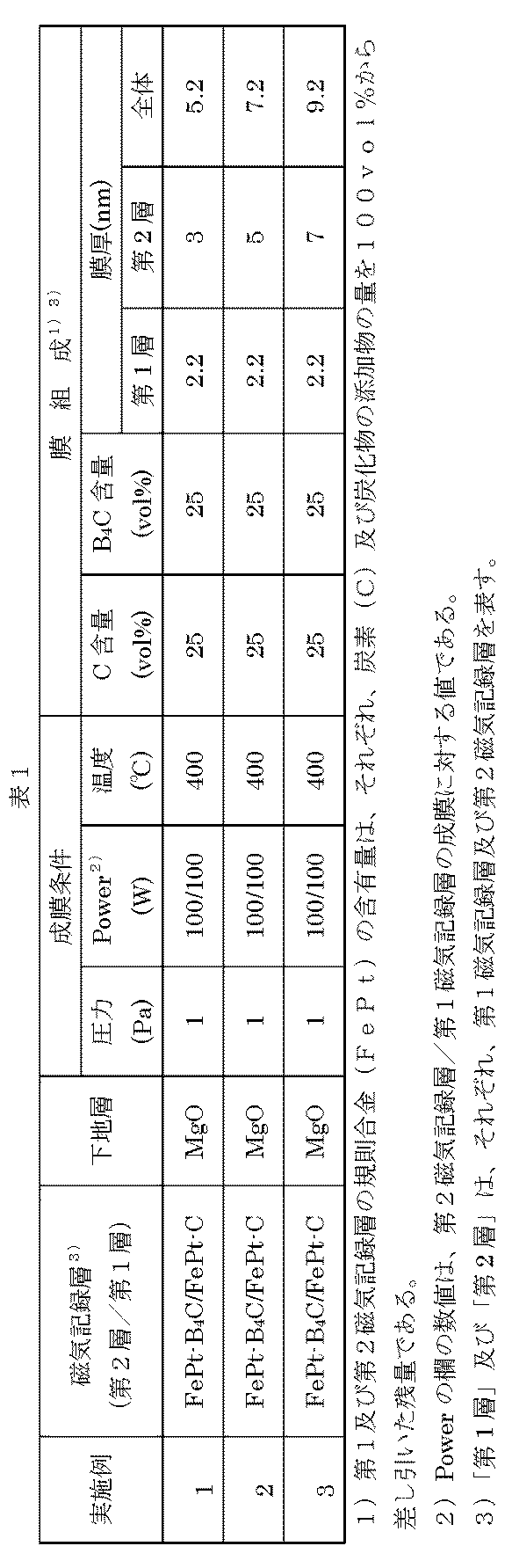
(ii) (実施例4~6)
非磁性基体と、その上に順次設けられるTa密着層、Cr下地層、MgOシード層、規則合金(FePt系)磁気記録層、及びカーボン(C)保護層を有する垂直磁気記録媒体を作製した。実施例4~6では、第1磁気記録層にFePt-Cを用い、第2磁気記録層にFePt-SiCを用いた例を示す。
非磁性基体と、その上に順次設けられるTa密着層、Cr下地層、MgOシード層、規則合金(FePt系)磁気記録層、及びカーボン(C)保護層を有する垂直磁気記録媒体を作製した。実施例4~6では、第1磁気記録層にFePt-Cを用い、第2磁気記録層にFePt-SiCを用いた例を示す。
非磁性基体として、化学強化ガラス基体(HOYA社製N-10ガラス基体)を準備した。非磁性基体を、スパッタ装置内に導入した。Ta密着層から、C保護層までの成膜は、大気解放することなく、インライン式の成膜装置で成膜した。Ta密着層は、純Taターゲットを用いて、Ar雰囲気中でDCマグネトロンスパッタ法により、膜厚5nmで成膜した。次に、Cr下地層は、純Crターゲットを用いて、Ar雰囲気中でDCマグネトロンスパッタ法により、膜厚20nmで成膜した。
次に、基体を300℃に加熱し、MgOターゲットを用いて、RFスパッタリング法で、膜厚5nmのシード層を成膜した。シード層であるMgO層は、真空度0.1PaのArガス雰囲気中で、RFパワー200Wで成膜した。
次に、第1磁気記録層を成膜した。第1磁気記録層はFePt-C層である。まず、上記の各層を成膜した基体を400℃に加熱し、成膜時の組成が表2に記載の、FePt(vol%)-C(vol%)となるように調製されたFePt及びCを含むターゲットを用いて、DCマグネトロンスパッタ法により、表2に示した膜厚の第1磁気記録層を成膜した。第1磁気記録層(FeP-C層)は、真空度1.0PaのArガス雰囲気中、DCパワー100Wで成膜した。
次に、第2磁気記録層を成膜した。本実施例の第2磁気記録層はFePt-SiC層である。成膜は以下の通りに行った。上記のように第1磁気記録層を成膜した基体を400℃に加熱した状態で、表2に記載の、FePt(vol%)-SiC(vol%)となるように調製されたFePt及びSiCを含むターゲットを用いて、DCマグネトロンスパッタ法により、表2に示した膜厚の第2磁気記録層を成膜した。第2磁気記録層(FeP-SiC層)は、真空度1.0PaのArガス雰囲気中、DCパワー100Wで成膜した。
次に、Arガス雰囲気中でカーボンターゲットを用いたDCマグネトロンスパッタリング法により、膜厚3nmのカーボン保護層を形成し、磁気記録媒体を得た。

(iii) (実施例7~17)
非磁性基体と、その上に順次設けられるTa密着層、Cr下地層、MgOシード層、規則合金(FePt系)磁気記録層、及びカーボン(C)保護層を有する垂直磁気記録媒体を作製した。実施例7~17では、第1磁気記録層にFePt-Cを用い、第2磁気記録層にFePt-B-Cを用いた例を示す。実施例7~17は、第1磁気記録層の炭素(C)の含有量を40vol%又は25vol%に固定し、第2磁気記録層のホウ素(B)及び炭素(C)の含有割合を変化させて磁気特性を評価した例である。ここで、実施例7~10は、第1磁気記録層の炭素(C)含有量を40vol%、第2磁気記録層のB-C全量を25vol%にそれぞれ固定し、第2磁気記録層のホウ素(B)及び炭素(C)の含有割合を変化させた例である。また、実施例11~12は、第1磁気記録層の炭素(C)含有量を25vol%、第2磁気記録層のB-C全量を25vol%にそれぞれ固定し、第2磁気記録層のホウ素(B)及び炭素(C)の含有割合を変化させた例である。さらに、実施例13~17は、第1磁気記録層のC含有量を40vol%に固定し、第2磁気記録層のB-C全量を変化させた例である。
非磁性基体と、その上に順次設けられるTa密着層、Cr下地層、MgOシード層、規則合金(FePt系)磁気記録層、及びカーボン(C)保護層を有する垂直磁気記録媒体を作製した。実施例7~17では、第1磁気記録層にFePt-Cを用い、第2磁気記録層にFePt-B-Cを用いた例を示す。実施例7~17は、第1磁気記録層の炭素(C)の含有量を40vol%又は25vol%に固定し、第2磁気記録層のホウ素(B)及び炭素(C)の含有割合を変化させて磁気特性を評価した例である。ここで、実施例7~10は、第1磁気記録層の炭素(C)含有量を40vol%、第2磁気記録層のB-C全量を25vol%にそれぞれ固定し、第2磁気記録層のホウ素(B)及び炭素(C)の含有割合を変化させた例である。また、実施例11~12は、第1磁気記録層の炭素(C)含有量を25vol%、第2磁気記録層のB-C全量を25vol%にそれぞれ固定し、第2磁気記録層のホウ素(B)及び炭素(C)の含有割合を変化させた例である。さらに、実施例13~17は、第1磁気記録層のC含有量を40vol%に固定し、第2磁気記録層のB-C全量を変化させた例である。
非磁性基体として、化学強化ガラス基体(HOYA社製N-10ガラス基体)を準備した。非磁性基体を、スパッタ装置内に導入した。Ta密着層から、C保護層までの成膜は、大気解放することなく、インライン式の成膜装置で成膜した。Ta密着層は、純Taターゲットを用いて、Ar雰囲気中でDCマグネトロンスパッタ法により、膜厚5nmで成膜した。次に、Cr下地層は、純Crターゲットを用いて、Ar雰囲気中でDCマグネトロンスパッタ法により、膜厚20nmで成膜した。
次に、基体を300℃に加熱し、MgOターゲットを用いて、RFスパッタリング法で、膜厚5nmのシード層を成膜した。シード層であるMgO層は、真空度0.1PaのArガス雰囲気中で、RFパワー200Wで成膜した。
次に、第1磁気記録層を成膜した。第1磁気記録層はFePt-C層である。まず、上記の各層を成膜した基体を400℃に加熱し、成膜時の組成が表3に記載の、FePt(vol%)-C(vol%)となるように調製されたFePt及びCを含むターゲットを用いて、DCマグネトロンスパッタ法により、表3に示した膜厚の第1磁気記録層を成膜した。第1磁気記録層(FeP-C層)は、真空度1.0PaのArガス雰囲気中、DCパワー100Wで成膜した。
次に、第2磁気記録層を成膜した。本実施例の第2磁気記録層はFePt-B-C層である。成膜は以下の通りに行った。上記のように第1磁気記録層を成膜した基体を400℃に加熱した状態で、表3に記載の、FePt(vol%)-B-C(vol%)となるように調製されたFePt、ホウ素(B)及び炭素(C)を含むターゲットを用いて、DCマグネトロンスパッタ法により、表3に示した膜厚の第2磁気記録層を成膜した。第2磁気記録層(FeP-B-C層)は、真空度1.0PaのArガス雰囲気中、DCパワー100Wで成膜した。
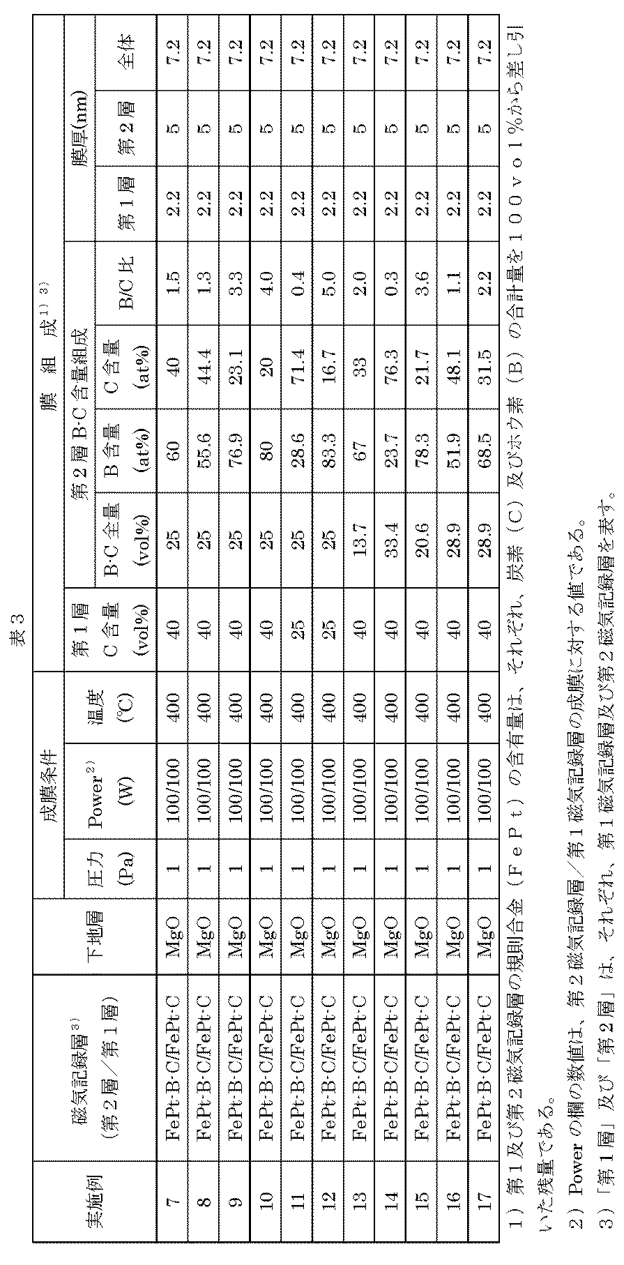
(iv) (比較例1~6)
比較例として、単層の磁気記録層を有する磁気記録媒体を作製した。磁気記録層は表4に示す組成の規則合金-非磁性材料であった。表4に示す磁気記録層を有する磁気記録媒体は、上記実施例1~6と同様に成膜した。但し、各比較例における磁気記録層は単層であるので、それぞれの比較例の各磁気記録層は、「FePt-C層」については、実施例1~6の第1磁気記録層の成膜条件により成膜し、「FePt-B4C層」については、実施例1~3の第2磁気記録層の成膜条件により成膜し、「FePt-SiC層」については、実施例4~6の第2磁気記録層の成膜条件により成膜した。
比較例として、単層の磁気記録層を有する磁気記録媒体を作製した。磁気記録層は表4に示す組成の規則合金-非磁性材料であった。表4に示す磁気記録層を有する磁気記録媒体は、上記実施例1~6と同様に成膜した。但し、各比較例における磁気記録層は単層であるので、それぞれの比較例の各磁気記録層は、「FePt-C層」については、実施例1~6の第1磁気記録層の成膜条件により成膜し、「FePt-B4C層」については、実施例1~3の第2磁気記録層の成膜条件により成膜し、「FePt-SiC層」については、実施例4~6の第2磁気記録層の成膜条件により成膜した。
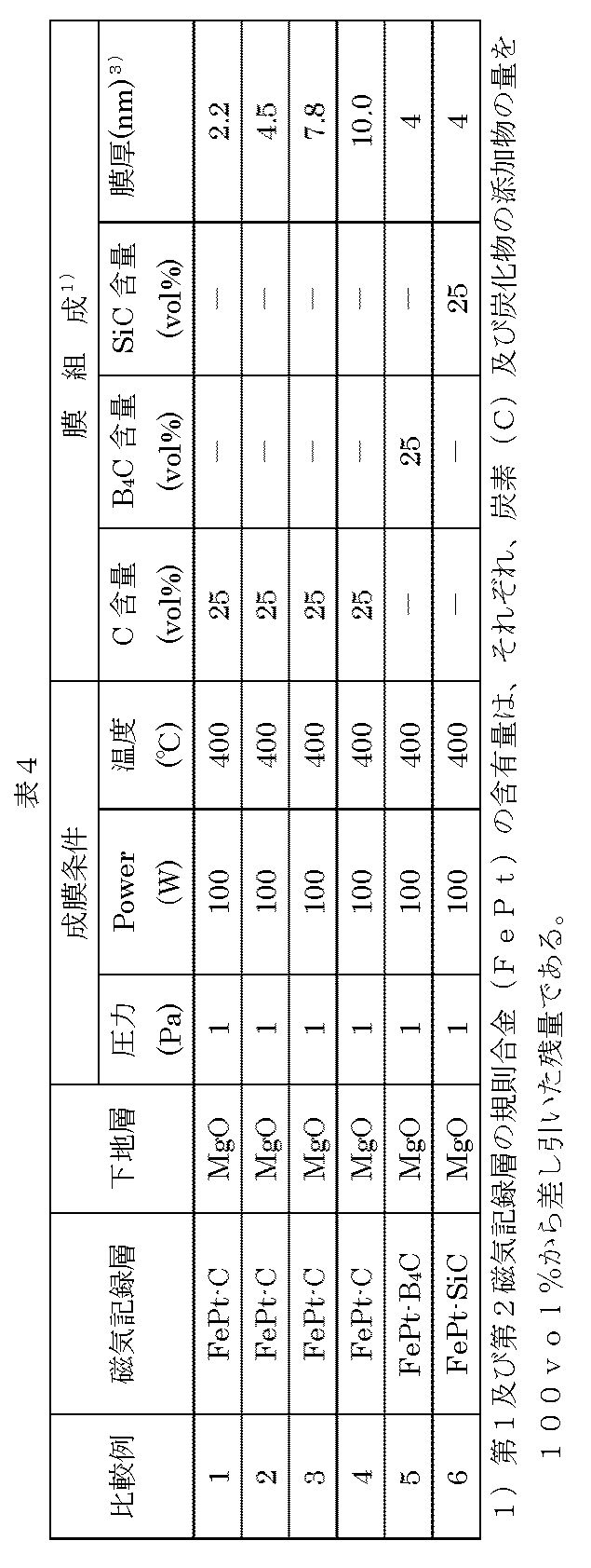
(v) (比較例7~8)
別の比較例として、2層の磁気記録層を有する磁気記録媒体を作製した。
別の比較例として、2層の磁気記録層を有する磁気記録媒体を作製した。
非磁性基体と、その上に順次設けられるTa密着層、Cr下地層、MgOシード層、規則合金(FePt系)磁気記録層、及びカーボン(C)保護層を有する垂直磁気記録媒体を作製した。比較例7及び8は、第1及び第2磁気記録層にFePt-Cを用いた例である。
非磁性基体として、化学強化ガラス基体(HOYA社製N-10ガラス基体)を準備した。非磁性基体を、スパッタ装置内に導入した。Ta密着層から、C保護層までの成膜は、大気解放することなく、インライン式の成膜装置で成膜した。Ta密着層は、純Taターゲットを用いて、Ar雰囲気中でDCマグネトロンスパッタ法により、膜厚5nmで成膜した。次に、Cr下地層は、純Crターゲットを用いて、Ar雰囲気中でDCマグネトロンスパッタ法により、膜厚20nmで成膜した。
次に、基体を300℃に加熱し、MgOターゲットを用いて、RFスパッタリング法で、膜厚5nmのシード層を成膜した。シード層であるMgO層は、真空度0.1PaのArガス雰囲気中で、RFパワー200Wで成膜した。
次に、第1磁気記録層を成膜した。第1磁気記録層はFePt-C層である。まず、上記の各層を成膜した基体を400℃に加熱し、成膜時の組成が表5に記載の、FePt(vol%)-C(vol%)となるように調製されたFePt及びCを含むターゲットを用いて、DCマグネトロンスパッタ法により、表5に示した膜厚の第1磁気記録層を成膜した。第1磁気記録層(FeP-C層)は、真空度1.0PaのArガス雰囲気中、DCパワー100Wで成膜した。
次に、第2磁気記録層を成膜した。本比較例の第2磁気記録層はFePt-C層である。成膜は以下の通りに行った。上記のように第1磁気記録層を成膜した基体を400℃に加熱した状態で、表5に記載の、FePt(vol%)-C(vol%)となるように調製されたFePtと、炭素若を含むターゲットを用いて、DCマグネトロンスパッタ法により、表5に示した膜厚の第2磁気記録層を成膜した。第2磁気記録層(FePt-C層)は、真空度1.0PaのArガス雰囲気中、DCパワー100Wで成膜した。

(vi)比較例9
本比較例は、2層の磁気記録媒体において、第2磁気記録層をFePt-SiO2とした例である。本比較例の成膜条件は、第2磁気記録層の成膜において、FePt(75vol%)-SiO2(25vol%)となるように調製されたFePt及びSiO2を含むターゲットを用い、第1磁気記録層及び第2磁気記録層の膜厚をそれぞれ3nm(総膜厚6nm)とした以外、上記比較例7~8と同様である。本比較例で得られた磁気記録媒体は1.80E+07erg/cm3のKuと、0.95のMr/Ms値を有していた。
本比較例は、2層の磁気記録媒体において、第2磁気記録層をFePt-SiO2とした例である。本比較例の成膜条件は、第2磁気記録層の成膜において、FePt(75vol%)-SiO2(25vol%)となるように調製されたFePt及びSiO2を含むターゲットを用い、第1磁気記録層及び第2磁気記録層の膜厚をそれぞれ3nm(総膜厚6nm)とした以外、上記比較例7~8と同様である。本比較例で得られた磁気記録媒体は1.80E+07erg/cm3のKuと、0.95のMr/Ms値を有していた。
(vii)(実施例1~17及び比較例1~8の評価)
(A)実施例1~6及び比較例1~6の結果
磁気記録媒体の評価は、磁気異方性定数(Ku)を評価することにより行った。具体的には、PPMS装置(Physical Property Measurement System)(Quantum Design社製)を用い、自発磁化の磁場印可角度依存性を評価し、試料振動型磁力計(VSM)を用いて飽和磁化(Ms)を求め、非特許文献3及び4に基づいてKu値を算出した。
(A)実施例1~6及び比較例1~6の結果
磁気記録媒体の評価は、磁気異方性定数(Ku)を評価することにより行った。具体的には、PPMS装置(Physical Property Measurement System)(Quantum Design社製)を用い、自発磁化の磁場印可角度依存性を評価し、試料振動型磁力計(VSM)を用いて飽和磁化(Ms)を求め、非特許文献3及び4に基づいてKu値を算出した。
上記磁気異方性定数に加え、保磁力(Hc)及びM-Hヒステリシスループのα値(保磁力近傍での磁化曲線の傾き)を求めた。なお、M-Hヒステリシスループのα値は、理想的なグラニュラー媒体の場合、α=1になることが知られている。
具体的な測定方法は、PPMS装置を用いM-Hヒステリシスループを評価し、VSMを用いて得た飽和磁化(Ms)から、保磁力(Hc)付近の傾き(dM/dH)からαを求めた。なお、αは0.6以上、2.5以下を良好な範囲とした。
結果を表6にまとめた。
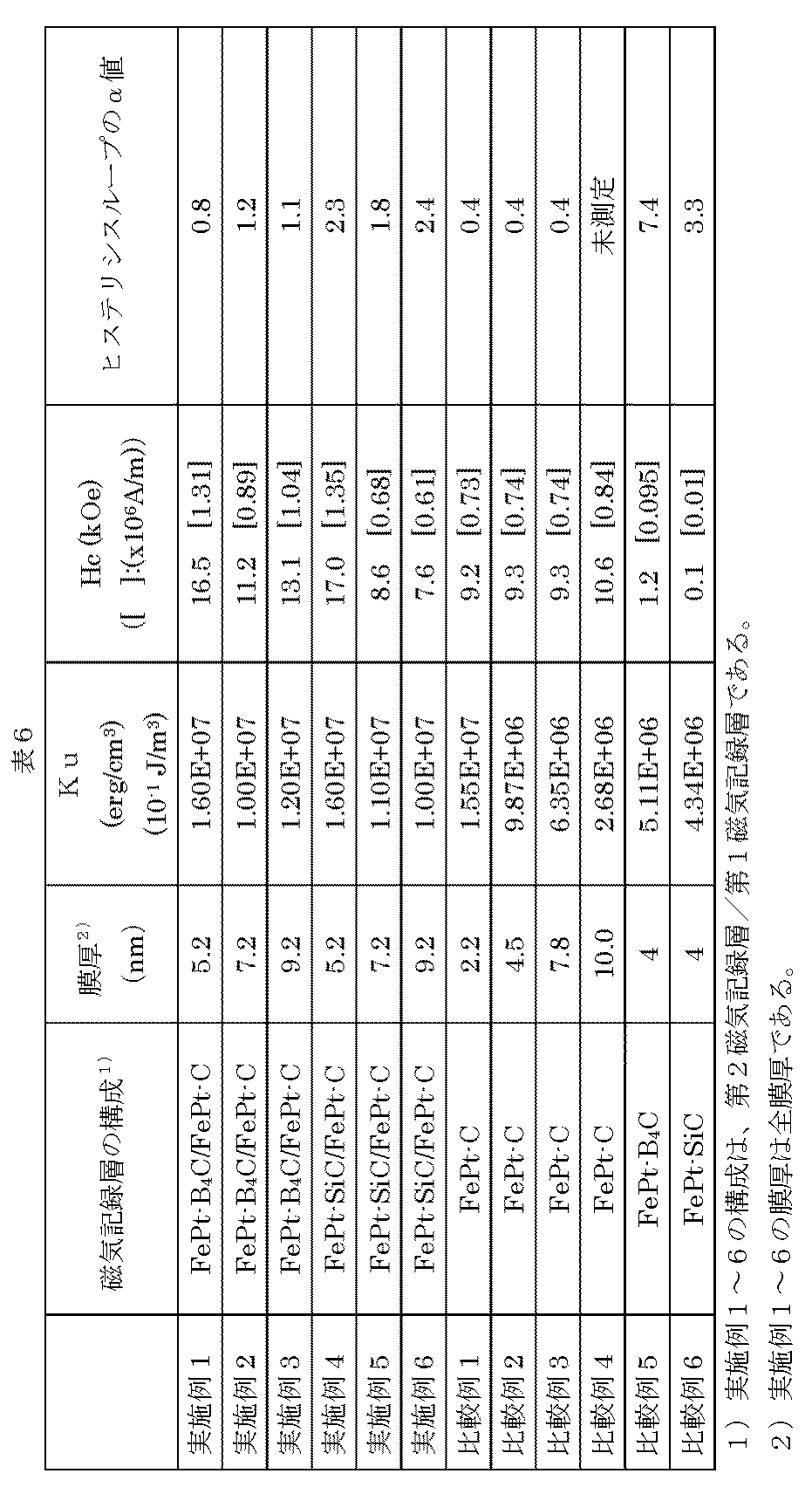
また、Kuの値を図5及び図6にまとめた。図5は、実施例1~3と比較例1~5の結果を比較したものであり、図6は、実施例4~6と比較例1~4及び6の結果を比較したものである。なお、図5には、参考として、後述する実施例11の結果を「B-C/C」(黒丸)として併記した。
(A-1)FePt-B4C/FePt-C(第2磁気記録層/第1磁気記録層)を含む磁気記録媒体の結果
Kuの値から、FePt-C単層の磁気記録媒体は、膜厚の増加と共に、Kuが大きく低下し、磁気異方性が膜厚の増加と共に低下することが分かる。また、FePt-B4C単層の磁気記録媒体は、膜厚が4nmでもKuが小さく、磁気異方性が低いことが分かる。一方、本発明の磁気記録媒体であるFePt-C上に、FePt-B4Cを積層して磁気記録媒体としたものでは、膜厚を増加させても、Ku値の大幅な低下を防ぐことができた。また、保磁力(Hc)及びヒステリシスループのα値についても比較例に比べ、良好な結果となった。
Kuの値から、FePt-C単層の磁気記録媒体は、膜厚の増加と共に、Kuが大きく低下し、磁気異方性が膜厚の増加と共に低下することが分かる。また、FePt-B4C単層の磁気記録媒体は、膜厚が4nmでもKuが小さく、磁気異方性が低いことが分かる。一方、本発明の磁気記録媒体であるFePt-C上に、FePt-B4Cを積層して磁気記録媒体としたものでは、膜厚を増加させても、Ku値の大幅な低下を防ぐことができた。また、保磁力(Hc)及びヒステリシスループのα値についても比較例に比べ、良好な結果となった。
(A-2)FePt-SiC/FePt-C(第2磁気記録層/第1磁気記録層)を含む磁気記録媒体の結果
Kuの値から、FePt-C単層の磁気記録媒体は、膜厚の増加と共に、Kuが大きく低下し、磁気異方性が膜厚の増加と共に低下することが分かる。また、FePt-SiC単層の磁気記録媒体は、膜厚が4nmでもKuが小さく、磁気異方性が低いことが分かる。一方、本発明の磁気記録媒体であるFePt-C上に、FePt-SiCを積層して磁気記録媒体としたものでは、FePt-C単層の磁気記録層を含む磁気記録媒体と比べて、厚膜を厚くしても、全体的にKu値を大きくすることができた。また、保磁力(Hc)及びヒステリシスループのα値についても比較例に比べ、良好な結果となった。
Kuの値から、FePt-C単層の磁気記録媒体は、膜厚の増加と共に、Kuが大きく低下し、磁気異方性が膜厚の増加と共に低下することが分かる。また、FePt-SiC単層の磁気記録媒体は、膜厚が4nmでもKuが小さく、磁気異方性が低いことが分かる。一方、本発明の磁気記録媒体であるFePt-C上に、FePt-SiCを積層して磁気記録媒体としたものでは、FePt-C単層の磁気記録層を含む磁気記録媒体と比べて、厚膜を厚くしても、全体的にKu値を大きくすることができた。また、保磁力(Hc)及びヒステリシスループのα値についても比較例に比べ、良好な結果となった。
更に、上記実験結果から、規則合金-非磁性材料中の非磁性材料の特性は以下のように考えられる。
a)炭素(C)はFePt結晶中での拡散が速く、FePt結晶粒内からの排出性が良い。しかしながら、膜厚の厚さ4nmで、既にFePt結晶粒(柱状成長)の上表面にも拡散し、FePt結晶の二次成長を引き起こす。
b)B4Cは、最も拡散が遅く、FePt結晶粒内に残りやすいが、FePt結晶粒(柱状成長)の上表面への拡散はない。そのため、大きなKuはとれないが、厚膜化してもKuの低下はない。B4Cは、MgOシード層上ではグラニュラー構造をとることが比較的難しい。
c)SiCは、炭素(C)とB4Cの中間的な特性であると考えられ、非磁性結晶粒界部分への排出は磁気記録層の成長と共にある程度進むと考えられる。しかし、例えば、上記実施例では、FePt-C磁気記録層の膜厚が2nmで、FePt-SiC磁気記録層の膜厚が3nmまでは、FePt-C単層の磁気記録層を含む磁気記録媒体ほどFePt結晶粒の柱状成長表面への、SiCの拡散が少なく、磁気記録層の膜厚の増加に伴うFePt結晶粒の二次成長を比較的抑えることができる。この結果、上記膜厚までは単層で非常に高いKuを得ることができる。しかしながら、FePt-SiC層の膜厚が厚くなるに伴い、FePt結晶粒の柱状成長表面上にもSiCが拡散するようになり、二次成長を引き起こす可能性を有する。
(B)実施例7~17及び比較例7~8の結果
これらの実施例では、磁気異方性定数(Ku)と、残留磁化(Mr)を飽和磁化(Ms)で割ったもの(Mr/Ms)を評価した。Mrは、VSMにより測定することができる。FePt-非磁性材料の磁性材料では、上述したように、炭素含有量が多いと、規則合金の成長阻害及び二次成長が起きるが、この二次成長状態では、Mr/Msが低くなる傾向がある。このため、本実施例での評価項目とした。また、Mr/Msが低いと、磁気記録の際に印加された磁界がなくなったとき、磁化の向きを磁化された方向に保てない粒子が存在することを意味し、磁気記録ではそのような粒子は再生信号におけるノイズ源となり、好ましくない。本発明では、Mr/Msの値は0.70を越える値が好適である。
これらの実施例では、磁気異方性定数(Ku)と、残留磁化(Mr)を飽和磁化(Ms)で割ったもの(Mr/Ms)を評価した。Mrは、VSMにより測定することができる。FePt-非磁性材料の磁性材料では、上述したように、炭素含有量が多いと、規則合金の成長阻害及び二次成長が起きるが、この二次成長状態では、Mr/Msが低くなる傾向がある。このため、本実施例での評価項目とした。また、Mr/Msが低いと、磁気記録の際に印加された磁界がなくなったとき、磁化の向きを磁化された方向に保てない粒子が存在することを意味し、磁気記録ではそのような粒子は再生信号におけるノイズ源となり、好ましくない。本発明では、Mr/Msの値は0.70を越える値が好適である。
実施例7~17及び比較例7~8における磁気記録媒体の磁気異方性定数(Ku)と、Mr/Msの結果を表7に示した。
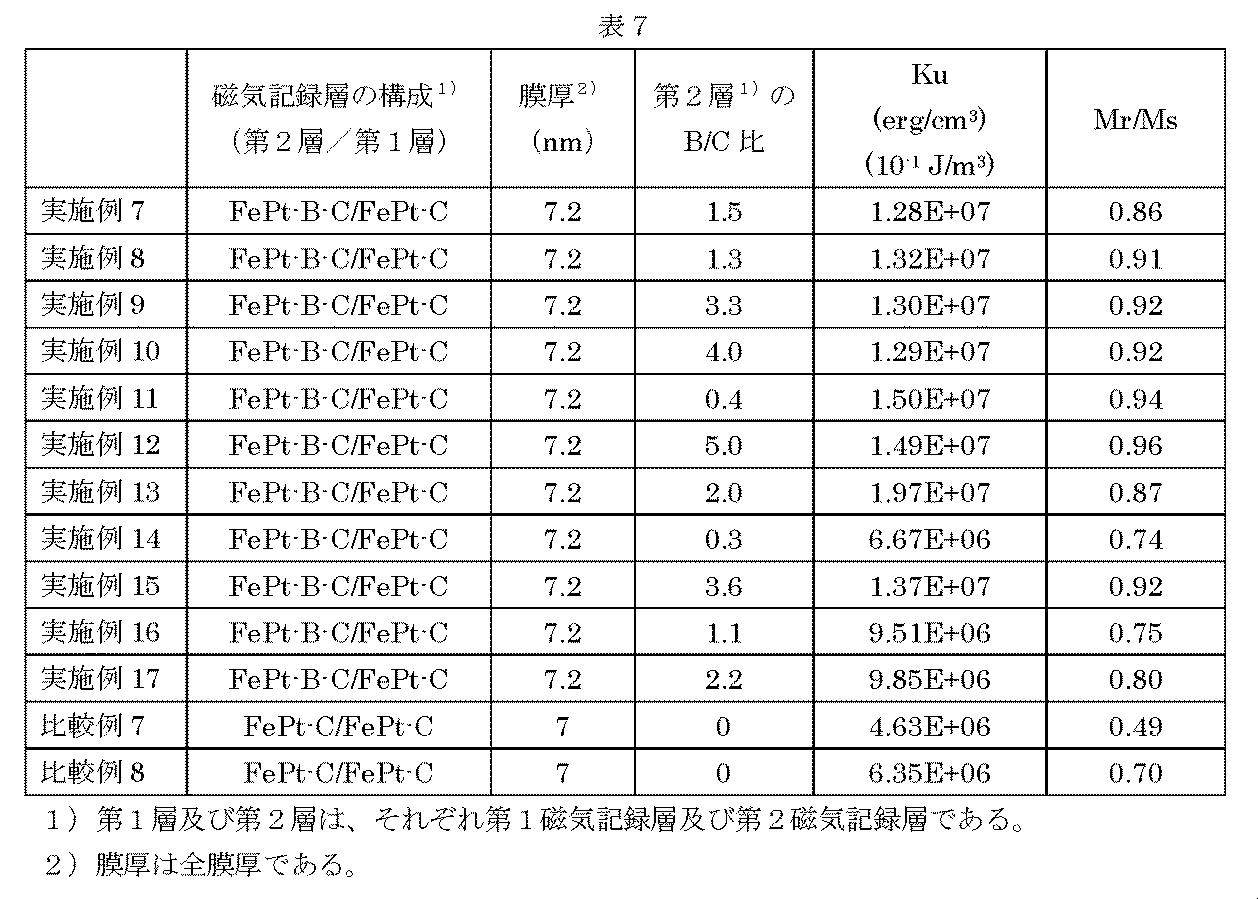
また、Mr/Msの値を図7~8にまとめた。図7は、実施例7~10及び比較例7の結果と、実施例11~12及び比較例8の結果を比較したものであり、図8は、図7の結果に、さらに実施例13~17の結果を加えて、比較したものである。
図9は、実施例13~17の第2磁気記録層(2層目)のホウ素(B)及び炭素(C)の全量に対するMr/Msの値をプロットしたものである。
(B-1)FePt-B-C/FePt-C(第2磁気記録層/第1磁気記録層)を含む磁気記録媒体の結果
実施例7~12と比較例7及び8を比較すると、比較例では規則金属-非磁性材料中の非磁性材料が炭素(C)のみであるため、二次成長が起こり、これによって、Ku及びMr/Msの値が実施例7~12に比べて低下している。
実施例7~12と比較例7及び8を比較すると、比較例では規則金属-非磁性材料中の非磁性材料が炭素(C)のみであるため、二次成長が起こり、これによって、Ku及びMr/Msの値が実施例7~12に比べて低下している。
上記実施例7~12の結果から、第2磁気記録層のホウ素(B)及び炭素(C)の割合(B/C比)は0.3以上が好ましく、0.4以上がより好ましいことがわかる(図7)。さらに、実施例13~17(これらは実施例7~12よりも広い範囲にわたって第2磁気記録層のB-C含有量を検討したものである)の結果からも、B/C比は0.3以上が好ましく、0.4以上がより好ましいことがわかる(図8)。
また、図9の結果から、FePt-B-Cにおけるホウ素(B)及び炭素(C)の総量が多くなるにつれて、Mr/Msの値も低下する傾向があることがわかる。また、実施例7~17の結果からも、規則金属-非磁性材料中の非磁性材料の含有量は、20vol%から40vol%が好ましく、20vol%から30vol%がより好ましいことがわかる。
図5において実施例1~6と併せて実施例11の結果を示したように、FePt-B-Cを用いた場合においても、実施例1~6と同様の優れた磁気特性を実現できた。
(C)実施例10及び比較例9の結果
本発明の磁気記録媒体と従来の磁気記録媒体を比較するため、透過型電子顕微鏡(TEM)により、実施例10と比較例9の磁気記録媒体の平面TEMを測定した。結果を図10A及び図10Bに示した。本発明の実施例10(図10A)では、膜厚が7.2nmと比較的厚いにもかかわらず、一定で均一な粒形成が得られていることがわかる。一方、比較例9(図10B)のようにFePr-SiO2を第2磁気記録層として形成した場合、膜厚が6nm程度ですでに粒形成は均一なものではなかった。
本発明の磁気記録媒体と従来の磁気記録媒体を比較するため、透過型電子顕微鏡(TEM)により、実施例10と比較例9の磁気記録媒体の平面TEMを測定した。結果を図10A及び図10Bに示した。本発明の実施例10(図10A)では、膜厚が7.2nmと比較的厚いにもかかわらず、一定で均一な粒形成が得られていることがわかる。一方、比較例9(図10B)のようにFePr-SiO2を第2磁気記録層として形成した場合、膜厚が6nm程度ですでに粒形成は均一なものではなかった。
(II) 実施例18~20
(i) (実施例18~20)
実施例18~20は、磁気記録層を3層以上の複数層とした例である。
(i) (実施例18~20)
実施例18~20は、磁気記録層を3層以上の複数層とした例である。
非磁性基体と、その上に順次設けられるTa密着層、Cr下地層、MgOシード層、規則合金(FePt系)磁気記録層、及びカーボン(C)保護層を有する垂直磁気記録媒体を作製した。実施例18~20では、奇数番の磁気記録層にFePt-Cを用い、偶数番の磁気記録層にFePt-B4Cを用いた(詳細な層構成及び各層の膜厚は表8に示した。)。
非磁性基体として、化学強化ガラス基体(HOYA社製N-10ガラス基体)を準備した。非磁性基体を、スパッタ装置内に導入した。Ta密着層から、C保護層までの成膜は、大気解放することなく、インライン式の成膜装置で成膜した。Ta密着層は、純Taターゲットを用いて、Ar雰囲気中でDCマグネトロンスパッタ法により、膜厚5nmで成膜した。次に、Cr下地層は、純Crターゲットを用いて、Ar雰囲気中でDCマグネトロンスパッタ法により、膜厚20nmで成膜した。
次に、基体を300℃に加熱し、MgOターゲットを用いて、RFスパッタリング法で、膜厚5nmのシード層を成膜した。シード層であるMgO層は、真空度0.1PaのArガス雰囲気中で、RFパワー200Wで成膜した。
次に、第1磁気記録層を成膜した。第1磁気記録層はFePt-C層である。まず、上記の各層を成膜した基体を400℃に加熱し、成膜時の組成が表1に記載の、FePt(vol%)-C(vol%)となるように調製されたFePt及びCを含むターゲットを用いて、DCマグネトロンスパッタ法により、表8に示した膜厚の第1磁気記録層を成膜した。第1磁気記録層(FeP-C層)は、真空度1.0PaのArガス雰囲気中、DCパワー100Wで成膜した。
次に、第2磁気記録層を成膜した。本実施例の第2磁気記録層はFePt-B4C層である。成膜は以下の通りに行った。上記のように第1磁気記録層を成膜した基体を400℃に加熱した状態で、表8に記載の、FePt(vol%)-B4C(vol%)となるように調製されたFePt及び炭化ホウ素を含むターゲットを用いて、DCマグネトロンスパッタ法により、表1に示した膜厚の第2磁気記録層を成膜した。第2磁気記録層(FeP-B4C層)は、真空度1.0PaのArガス雰囲気中、DCパワー100Wで成膜した。
上記第1磁気記録層及び第2磁気記録層の手順を必要な回数繰り返して所望の数の層を有する磁気記録層を形成した。
次に、Arガス雰囲気中でカーボンターゲットを用いたDCマグネトロンスパッタリング法により、膜厚3nmのカーボン保護層を形成し、磁気記録媒体を得た。
(ii)(評価)
本実施例における磁気記録媒体の評価は、磁気異方性定数(Ku)を評価することにより行った。評価方法は実施例1~6と同様である。
本実施例における磁気記録媒体の評価は、磁気異方性定数(Ku)を評価することにより行った。評価方法は実施例1~6と同様である。
上記磁気異方性定数に加え、保磁力(Hc)及びヒステリシスループのα値(保磁力近傍での磁化曲線の傾き)を求めた。評価方法は実施例1~6と同様である。
結果を表8に示した。なお、表8には、実施例1~3の結果を参考として併記した。
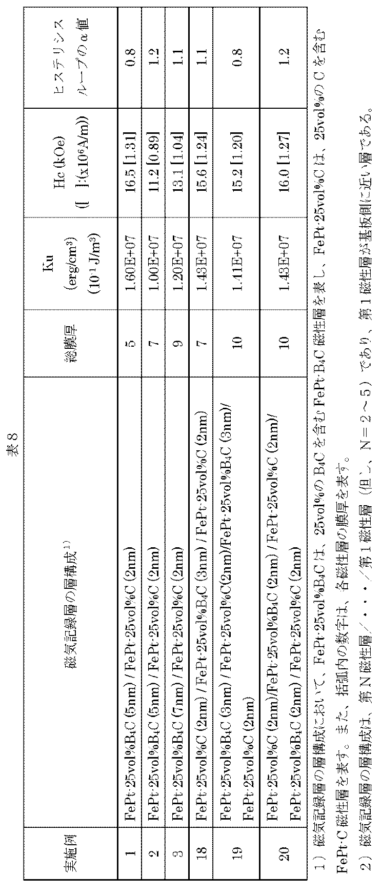
上記結果を図11に示した。図11は、磁気記録層の総膜厚に対して、Kuの値をプロットしたものである。
これらの結果から明らかなように、FePt-C層とFePt-B4C層を交互に複数積層することで、Ku、Hc及びヒステリシスループのα値を保持したまま、膜厚を更に厚くすることができる。
更に、実施例20の層構造の磁気記録層を有する磁気記録媒体と、実施例3の層構造の磁気記録層を有する磁気記録媒体の垂直TEMを測定した。結果を図12A及び図12Bに示す。これらの結果から明らかなように、2層構造の実施例3では、7nm程度の膜厚で規則合金の成長阻害が起こるが、更に多くの層を有する実施例20では、10nm程度の膜厚までこのようなことは起こらなかった。
(III) まとめ
上記実施例及び比較例の実験結果の比較から、本発明の1つの実施形態として、FePt-Cを第1磁気記録層として使用し、これと組合せて、第2磁気記録層として、上記実施例で使用した規則合金を含む磁性結晶粒-炭素含有非磁性材料のグラニュラー構造を有する磁気記録層を設けることで、高い磁気異方性を維持しながら磁気記録層全体の厚膜化を実現することが可能となった。更に、本発明の別の1つの実施形態として、FePt-C層と、規則合金を含む磁性結晶粒-炭素含有非磁性材料を交互に複数層設けることにより、高い磁気異方性を維持しながら磁気記録層全体の膜厚の更なる厚膜化を実現できた。
上記実施例及び比較例の実験結果の比較から、本発明の1つの実施形態として、FePt-Cを第1磁気記録層として使用し、これと組合せて、第2磁気記録層として、上記実施例で使用した規則合金を含む磁性結晶粒-炭素含有非磁性材料のグラニュラー構造を有する磁気記録層を設けることで、高い磁気異方性を維持しながら磁気記録層全体の厚膜化を実現することが可能となった。更に、本発明の別の1つの実施形態として、FePt-C層と、規則合金を含む磁性結晶粒-炭素含有非磁性材料を交互に複数層設けることにより、高い磁気異方性を維持しながら磁気記録層全体の膜厚の更なる厚膜化を実現できた。
本発明の磁気記録媒体は、熱アシスト式、マイクロ波アシスト式等のエネルギーアシスト式の磁気記録媒体を含めた、垂直磁気記録媒体を含む磁気記録装置に利用可能である。
20 非磁性基体
40、210 シード層
60 磁気記録層
62 第1磁気記録層
64 第2磁気記録層
80 保護層
100 磁気記録媒体
200 磁性結晶粒
230 規則合金の第1磁性結晶粒
250 規則合金の第2磁性結晶粒
270 非磁性結晶粒界
290、292、294 磁化容易軸
320 規則合金の添加材料(非磁性材料)の析出部分
400 磁性結晶粒(200)と非磁性材料(320)の混合領域
40、210 シード層
60 磁気記録層
62 第1磁気記録層
64 第2磁気記録層
80 保護層
100 磁気記録媒体
200 磁性結晶粒
230 規則合金の第1磁性結晶粒
250 規則合金の第2磁性結晶粒
270 非磁性結晶粒界
290、292、294 磁化容易軸
320 規則合金の添加材料(非磁性材料)の析出部分
400 磁性結晶粒(200)と非磁性材料(320)の混合領域
Claims (9)
- 非磁性基板及び磁気記録層を少なくとも含む垂直磁気記録媒体であって、
前記磁気記録層は、少なくとも第1磁気記録層及び第2磁気記録層を含む複数層からなり、
前記第1磁気記録層は、第1磁性結晶粒と、前記第1磁性結晶粒を取り囲む第1非磁性結晶粒界とを含むグラニュラー構造を有し、前記第1磁性結晶粒は規則合金を含み、前記第1非磁性結晶粒界は炭素からなり、
前記第2磁気記録層は、第2磁性結晶粒と、前記第2磁性結晶粒を取り囲む第2非磁性結晶粒界とを含むグラニュラー構造を有し、前記第2磁性結晶粒は規則合金を含み、前記第2非磁性結晶粒界は、炭素、ホウ素又はケイ素から選択される1つ以上の材料からなるものであることを特徴とする垂直磁気記録媒体。 - 非磁性基板及び磁気記録層を少なくとも含む垂直磁気記録媒体であって、
前記磁気記録層は、少なくとも第1磁気記録層及び第2磁気記録層を含む複数層からなり、
前記第1磁気記録層は、第1磁性結晶粒と、前記第1磁性結晶粒を取り囲む第1非磁性結晶粒界とを含むグラニュラー構造を有し、前記第1磁性結晶粒は規則合金を含み、前記第1非磁性結晶粒界は炭素からなり、
前記第2磁気記録層は、第2磁性結晶粒と、前記第2磁性結晶粒を取り囲む第2非磁性結晶粒界とを含むグラニュラー構造を有し、前記第2磁性結晶粒は規則合金を含み、前記第2非磁性結晶粒界は炭化物であることを特徴とする垂直磁気記録媒体。 - 前記炭化物は、ホウ素(B)炭化物又はケイ素(Si)炭化物であることを特徴とする請求項2に記載の垂直磁気記録媒体。
- 前記炭化物は、炭化ホウ素(B4C)又は炭化ケイ素(SiC)であることを特徴とする請求項2又は3に記載の垂直磁気記録媒体。
- 前記第2非磁性結晶粒界の材料の含有量は、20vol%から50vol%であることを特徴とする請求項1から4のいずれか1項に記載の垂直磁気記録媒体。
- 前記第1磁性結晶粒及び前記第2磁性結晶粒はL10型の規則合金を含むことを特徴とする請求項1から5のいずれか1項に記載の垂直磁気記録媒体。
- 前記L10型の規則合金は、Fe及びPtを含むことを特徴とする請求項6に記載の垂直磁気記録媒体。
- 前記第1磁気記録層の膜厚は、4nm以下であることを特徴とする請求項1~7のいずれか1項に記載の垂直磁気記録媒体。
- 前記第1磁気記録層又は第2磁気記録層を複数層有し、且つ、前記第1磁気記録層と第2磁気記録層が交互に積層されることを特徴とする請求項1から8のいずれか1項に記載の垂直磁気記録媒体。
Priority Applications (5)
| Application Number | Priority Date | Filing Date | Title |
|---|---|---|---|
| JP2014523137A JP5783330B2 (ja) | 2012-12-06 | 2013-12-06 | 垂直磁気記録媒体 |
| SG11201408003UA SG11201408003UA (en) | 2012-12-06 | 2013-12-06 | Perpendicular magnetic recording medium |
| CN201380029987.3A CN104364846B (zh) | 2012-12-06 | 2013-12-06 | 垂直磁记录介质 |
| MYPI2014703611A MY167287A (en) | 2012-12-06 | 2013-12-06 | Perpendicular magnetic recording medium |
| US14/560,708 US9672855B2 (en) | 2012-12-06 | 2014-12-04 | Perpendicular magnetic recording medium |
Applications Claiming Priority (2)
| Application Number | Priority Date | Filing Date | Title |
|---|---|---|---|
| JP2012267588 | 2012-12-06 | ||
| JP2012-267588 | 2012-12-06 |
Related Child Applications (1)
| Application Number | Title | Priority Date | Filing Date |
|---|---|---|---|
| US14/560,708 Continuation US9672855B2 (en) | 2012-12-06 | 2014-12-04 | Perpendicular magnetic recording medium |
Publications (1)
| Publication Number | Publication Date |
|---|---|
| WO2014087672A1 true WO2014087672A1 (ja) | 2014-06-12 |
Family
ID=50883112
Family Applications (1)
| Application Number | Title | Priority Date | Filing Date |
|---|---|---|---|
| PCT/JP2013/007213 Ceased WO2014087672A1 (ja) | 2012-12-06 | 2013-12-06 | 垂直磁気記録媒体 |
Country Status (6)
| Country | Link |
|---|---|
| US (1) | US9672855B2 (ja) |
| JP (1) | JP5783330B2 (ja) |
| CN (1) | CN104364846B (ja) |
| MY (1) | MY167287A (ja) |
| SG (1) | SG11201408003UA (ja) |
| WO (1) | WO2014087672A1 (ja) |
Cited By (6)
| Publication number | Priority date | Publication date | Assignee | Title |
|---|---|---|---|---|
| WO2015037425A1 (ja) * | 2013-09-12 | 2015-03-19 | 独立行政法人物質・材料研究機構 | 垂直磁気記録媒体およびその製造方法 |
| GB2534649A (en) * | 2014-11-26 | 2016-08-03 | HGST Netherlands BV | Heat assisted magnetic recording (HAMR) media having a highly ordered crystalline structure |
| US10714138B2 (en) | 2015-09-17 | 2020-07-14 | Fuji Electric Co., Ltd. | Perpendicular magnetic recording medium |
| JP2022150658A (ja) * | 2021-03-26 | 2022-10-07 | 昭和電工株式会社 | 磁気記録媒体及び磁気記憶装置 |
| JP7622147B2 (ja) | 2022-08-25 | 2025-01-27 | ウェスタン デジタル テクノロジーズ インコーポレーテッド | 熱アシスト磁気記録を改善するように構成された、選択された分離体を有する媒体構造 |
| JP7642435B2 (ja) | 2021-05-10 | 2025-03-10 | 株式会社レゾナック・ハードディスク | 磁気記録媒体、磁気記録媒体の製造方法及び磁気記憶装置 |
Families Citing this family (9)
| Publication number | Priority date | Publication date | Assignee | Title |
|---|---|---|---|---|
| JP6163744B2 (ja) * | 2012-12-06 | 2017-07-19 | 富士電機株式会社 | 垂直磁気記録媒体 |
| US10020016B2 (en) * | 2013-12-10 | 2018-07-10 | Fuji Electric Co., Ltd. | Perpendicular magnetic recording medium |
| JP6594633B2 (ja) * | 2015-02-23 | 2019-10-23 | 富士電機株式会社 | 磁気記録媒体 |
| JP2017224371A (ja) * | 2016-06-15 | 2017-12-21 | 昭和電工株式会社 | 磁気記録媒体及び磁気記憶装置 |
| US11804321B2 (en) * | 2020-11-20 | 2023-10-31 | Samsung Electronics Co., Ltd. | Tunable templating layers for perpendicularly magnetized Heusler films |
| US11626134B1 (en) * | 2021-12-29 | 2023-04-11 | Seagate Technology Llc | Media design and write technique for creating neutral polarity transition zones |
| US11626136B1 (en) | 2021-12-29 | 2023-04-11 | Seagate Technology Llc | Three-state single-pass recording in HAMR device with dual recording layers |
| US12412598B2 (en) | 2023-09-01 | 2025-09-09 | Western Digital Technologies, Inc. | Media underlayer structure for heat-assisted magnetic recording and media fabrication methods therefor |
| US12308056B2 (en) | 2023-10-12 | 2025-05-20 | Western Digital Technologies, Inc. | Magnetic recording medium with magnesium-titanium oxide (MTO) layer formed using pulsed direct current sputter deposition |
Citations (6)
| Publication number | Priority date | Publication date | Assignee | Title |
|---|---|---|---|---|
| JP2001351217A (ja) * | 2000-06-08 | 2001-12-21 | Fujitsu Ltd | 磁気記録媒体 |
| JP2007026558A (ja) * | 2005-07-15 | 2007-02-01 | Univ Of Tokyo | 磁気記録媒体及びその製造方法 |
| JP2010102816A (ja) * | 2008-09-29 | 2010-05-06 | Hoya Corp | 垂直磁気記録媒体 |
| JP2010153030A (ja) * | 2010-03-02 | 2010-07-08 | Toshiba Corp | 磁気記録媒体及び磁気記録媒体の製造法、並びに磁気記録再生装置 |
| JP2012048784A (ja) * | 2010-08-26 | 2012-03-08 | Hitachi Ltd | 垂直磁気記録媒体及びその製造方法 |
| JP2012160242A (ja) * | 2011-02-02 | 2012-08-23 | Fuji Electric Co Ltd | 熱アシスト記録装置用の磁気記録媒体およびその製造方法 |
Family Cites Families (20)
| Publication number | Priority date | Publication date | Assignee | Title |
|---|---|---|---|---|
| JP3786453B2 (ja) | 1994-07-11 | 2006-06-14 | 株式会社東芝 | 磁気記録媒体および磁気記録再生装置 |
| US5652054A (en) | 1994-07-11 | 1997-07-29 | Kabushiki Kaisha Toshiba | Magnetic recording media having a magnetic thin film made of magnetic metals grains and nonmagnetic matrix |
| JP4874526B2 (ja) * | 2004-03-25 | 2012-02-15 | 株式会社東芝 | 磁気記録媒体及び磁気記録媒体の製造法、並びに磁気記録再生装置 |
| US7521137B2 (en) | 2005-01-12 | 2009-04-21 | Seagate Technology Llc | Patterned thin films and use of such films as thermal control layers in heat assisted magnetic recording media |
| JP2006309919A (ja) * | 2005-03-30 | 2006-11-09 | Fujitsu Ltd | 垂直磁気記録媒体、その製造方法および磁気記憶装置 |
| JP2006190485A (ja) | 2006-04-12 | 2006-07-20 | Fujitsu Ltd | 垂直磁気記録媒体および磁気記憶装置 |
| JP4165580B2 (ja) | 2006-06-29 | 2008-10-15 | トヨタ自動車株式会社 | 画像処理装置及び画像処理プログラム |
| JP2008091024A (ja) | 2007-12-25 | 2008-04-17 | Toshiba Corp | 垂直磁気記録媒体 |
| JP2008097824A (ja) | 2008-01-07 | 2008-04-24 | Fuji Electric Device Technology Co Ltd | 垂直磁気記録媒体およびその製造方法 |
| US20100189886A1 (en) | 2009-01-27 | 2010-07-29 | Seagate Technology Llc | Method For Making Data Storage Media |
| US8133332B2 (en) * | 2009-02-12 | 2012-03-13 | Seagate Technology Llc | Method for preparing FePt media at low ordering temperature and fabrication of exchange coupled composite media and gradient anisotropy media for magnetic recording |
| JP5670638B2 (ja) | 2010-01-26 | 2015-02-18 | 昭和電工株式会社 | 熱アシスト磁気記録媒体及び磁気記録再生装置 |
| US8530065B1 (en) * | 2010-08-10 | 2013-09-10 | WD Media, LLC | Composite magnetic recording medium |
| JP5145437B2 (ja) | 2011-03-02 | 2013-02-20 | 株式会社日立製作所 | 磁気記録媒体 |
| US8507114B2 (en) * | 2011-06-30 | 2013-08-13 | Seagate Technology Llc | Recording layer for heat assisted magnetic recording |
| US20130170075A1 (en) * | 2011-12-28 | 2013-07-04 | Hitachi Global Storage Technologies Netherlands B.V. | System, method and apparatus for magnetic media with a non-continuous metallic seed layer |
| JP5880686B2 (ja) * | 2012-03-22 | 2016-03-09 | 富士電機株式会社 | 熱アシスト磁気記録用の磁気記録媒体 |
| US8721903B2 (en) * | 2012-04-05 | 2014-05-13 | HGST Netherlands B.V. | Method for planarizing a perpendicular magnetic recording disk for thermally-assisted recording (TAR) |
| JP6163744B2 (ja) * | 2012-12-06 | 2017-07-19 | 富士電機株式会社 | 垂直磁気記録媒体 |
| US9324353B2 (en) * | 2013-11-19 | 2016-04-26 | HGST Netherlands B.V. | Dual segregant heat assisted magnetic recording (HAMR) media |
-
2013
- 2013-12-06 MY MYPI2014703611A patent/MY167287A/en unknown
- 2013-12-06 SG SG11201408003UA patent/SG11201408003UA/en unknown
- 2013-12-06 WO PCT/JP2013/007213 patent/WO2014087672A1/ja not_active Ceased
- 2013-12-06 JP JP2014523137A patent/JP5783330B2/ja active Active
- 2013-12-06 CN CN201380029987.3A patent/CN104364846B/zh active Active
-
2014
- 2014-12-04 US US14/560,708 patent/US9672855B2/en active Active
Patent Citations (6)
| Publication number | Priority date | Publication date | Assignee | Title |
|---|---|---|---|---|
| JP2001351217A (ja) * | 2000-06-08 | 2001-12-21 | Fujitsu Ltd | 磁気記録媒体 |
| JP2007026558A (ja) * | 2005-07-15 | 2007-02-01 | Univ Of Tokyo | 磁気記録媒体及びその製造方法 |
| JP2010102816A (ja) * | 2008-09-29 | 2010-05-06 | Hoya Corp | 垂直磁気記録媒体 |
| JP2010153030A (ja) * | 2010-03-02 | 2010-07-08 | Toshiba Corp | 磁気記録媒体及び磁気記録媒体の製造法、並びに磁気記録再生装置 |
| JP2012048784A (ja) * | 2010-08-26 | 2012-03-08 | Hitachi Ltd | 垂直磁気記録媒体及びその製造方法 |
| JP2012160242A (ja) * | 2011-02-02 | 2012-08-23 | Fuji Electric Co Ltd | 熱アシスト記録装置用の磁気記録媒体およびその製造方法 |
Cited By (9)
| Publication number | Priority date | Publication date | Assignee | Title |
|---|---|---|---|---|
| WO2015037425A1 (ja) * | 2013-09-12 | 2015-03-19 | 独立行政法人物質・材料研究機構 | 垂直磁気記録媒体およびその製造方法 |
| GB2534649A (en) * | 2014-11-26 | 2016-08-03 | HGST Netherlands BV | Heat assisted magnetic recording (HAMR) media having a highly ordered crystalline structure |
| GB2534649B (en) * | 2014-11-26 | 2019-07-24 | HGST Netherlands BV | Heat assisted magnetic recording (HAMR) media having a highly ordered crystalline structure |
| US10714138B2 (en) | 2015-09-17 | 2020-07-14 | Fuji Electric Co., Ltd. | Perpendicular magnetic recording medium |
| JP2022150658A (ja) * | 2021-03-26 | 2022-10-07 | 昭和電工株式会社 | 磁気記録媒体及び磁気記憶装置 |
| JP7643135B2 (ja) | 2021-03-26 | 2025-03-11 | 株式会社レゾナック・ハードディスク | 磁気記録媒体及び磁気記憶装置 |
| JP7642435B2 (ja) | 2021-05-10 | 2025-03-10 | 株式会社レゾナック・ハードディスク | 磁気記録媒体、磁気記録媒体の製造方法及び磁気記憶装置 |
| JP7622147B2 (ja) | 2022-08-25 | 2025-01-27 | ウェスタン デジタル テクノロジーズ インコーポレーテッド | 熱アシスト磁気記録を改善するように構成された、選択された分離体を有する媒体構造 |
| US12272392B2 (en) | 2022-08-25 | 2025-04-08 | Western Digital Technologies, Inc. | Media structure with selected segregants configured to improve heat-assisted magnetic recording |
Also Published As
| Publication number | Publication date |
|---|---|
| US20150132608A1 (en) | 2015-05-14 |
| CN104364846A (zh) | 2015-02-18 |
| US9672855B2 (en) | 2017-06-06 |
| MY167287A (en) | 2018-08-15 |
| JP5783330B2 (ja) | 2015-09-24 |
| JPWO2014087672A1 (ja) | 2017-01-05 |
| SG11201408003UA (en) | 2015-01-29 |
| CN104364846B (zh) | 2019-11-05 |
Similar Documents
| Publication | Publication Date | Title |
|---|---|---|
| JP5783330B2 (ja) | 垂直磁気記録媒体 | |
| JP6274305B2 (ja) | 磁気記録媒体 | |
| JP6439869B2 (ja) | 磁気記録媒体の製造方法 | |
| US9093099B2 (en) | Perpendicular magnetic recording medium and method for manufacturing the same | |
| US10020016B2 (en) | Perpendicular magnetic recording medium | |
| JP6168066B2 (ja) | 垂直磁気記録媒体 | |
| JP6447739B2 (ja) | 垂直磁気記録媒体 | |
| JP6665963B2 (ja) | 磁気記録媒体 | |
| JP5874872B1 (ja) | 垂直磁気記録媒体の製造方法 | |
| CN107077864A (zh) | 磁记录介质 | |
| JP2004213869A (ja) | 垂直磁気記録媒体およびその製造方法 | |
| WO2017122593A1 (ja) | 磁気記録媒体およびこれを製造する方法 | |
| WO2017122575A1 (ja) | 磁気記録媒体 | |
| JP6428943B2 (ja) | 磁気記録媒体 | |
| JP2006236486A (ja) | 磁気記録媒体及びその製造方法 |
Legal Events
| Date | Code | Title | Description |
|---|---|---|---|
| ENP | Entry into the national phase |
Ref document number: 2014523137 Country of ref document: JP Kind code of ref document: A |
|
| 121 | Ep: the epo has been informed by wipo that ep was designated in this application |
Ref document number: 13861291 Country of ref document: EP Kind code of ref document: A1 |
|
| NENP | Non-entry into the national phase |
Ref country code: DE |
|
| 122 | Ep: pct application non-entry in european phase |
Ref document number: 13861291 Country of ref document: EP Kind code of ref document: A1 |