WO2014080701A1 - 取引装置 - Google Patents
取引装置 Download PDFInfo
- Publication number
- WO2014080701A1 WO2014080701A1 PCT/JP2013/077390 JP2013077390W WO2014080701A1 WO 2014080701 A1 WO2014080701 A1 WO 2014080701A1 JP 2013077390 W JP2013077390 W JP 2013077390W WO 2014080701 A1 WO2014080701 A1 WO 2014080701A1
- Authority
- WO
- WIPO (PCT)
- Prior art keywords
- user
- wheelchair
- input
- screen
- transaction
- Prior art date
- Legal status (The legal status is an assumption and is not a legal conclusion. Google has not performed a legal analysis and makes no representation as to the accuracy of the status listed.)
- Ceased
Links
Images









Classifications
-
- G—PHYSICS
- G06—COMPUTING OR CALCULATING; COUNTING
- G06Q—INFORMATION AND COMMUNICATION TECHNOLOGY [ICT] SPECIALLY ADAPTED FOR ADMINISTRATIVE, COMMERCIAL, FINANCIAL, MANAGERIAL OR SUPERVISORY PURPOSES; SYSTEMS OR METHODS SPECIALLY ADAPTED FOR ADMINISTRATIVE, COMMERCIAL, FINANCIAL, MANAGERIAL OR SUPERVISORY PURPOSES, NOT OTHERWISE PROVIDED FOR
- G06Q20/00—Payment architectures, schemes or protocols
- G06Q20/08—Payment architectures
- G06Q20/18—Payment architectures involving self-service terminals [SST], vending machines, kiosks or multimedia terminals
-
- G—PHYSICS
- G07—CHECKING-DEVICES
- G07F—COIN-FREED OR LIKE APPARATUS
- G07F19/00—Complete banking systems; Coded card-freed arrangements adapted for dispensing or receiving monies or the like and posting such transactions to existing accounts, e.g. automatic teller machines
- G07F19/20—Automatic teller machines [ATMs]
-
- G—PHYSICS
- G07—CHECKING-DEVICES
- G07F—COIN-FREED OR LIKE APPARATUS
- G07F9/00—Details other than those peculiar to special kinds or types of apparatus
- G07F9/10—Casings or parts thereof, e.g. with means for heating or cooling
Definitions
- the present invention relates to a transaction apparatus and can be applied to, for example, an ATM (Automated Teller Machine) installed in a financial institution such as a bank or a convenience store.
- ATM Automated Teller Machine
- an ATM described in Japanese Patent Application Laid-Open No. 05-081511 is an ATM taking into account the convenience (operability and visibility) of both a wheelchair user and a wheelchair non-user (healthy person) who does not use a wheelchair. is there.
- the first operation unit arranged at a height considering the convenience of a wheelchair non-user and the height considering the convenience of a wheelchair user The second operation unit is provided separately.
- the present invention is a transaction apparatus having an input unit that receives an input from a user, wherein the height from the floor on which the user is positioned takes into account the convenience of wheelchair users and wheelchair non-users.
- a transaction apparatus in which the input unit is arranged so that a part or all of the first space is included in a first space that is in a range of 1 to 2 heights.
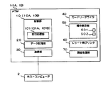
- FIG. 2 is a block diagram showing a functional configuration of the ATM 1 of the first embodiment.
- FIG. 3 is a perspective view of the ATM 1 according to the first embodiment.
- the ATM 1 is connected to the host computer 2 via the network and executes transaction processing (for example, transaction processing related to transaction) in cooperation with the host computer 2.
- transaction processing for example, transaction processing related to transaction
- the host computer 2 for example, a host computer capable of transaction processing using an existing ATM can be applied, and detailed description thereof is omitted.
- the ATM 1 has a control unit 10, a data storage unit 20, a communication unit 30, a card reader / writer 40, an operation display unit 50, a receipt printer 60, and a cash processing unit 70.
- the reference numerals in parentheses are those used in the second and third embodiments described later.
- the control unit 10 has a function of performing operation control and information processing of each unit in the ATM 1, and has a transaction processing unit 101.
- the data storage unit 20 is a data storage unit that stores various kinds of information necessary for the control unit 10 to perform information processing, and can be configured by various memories, for example.
- the transaction processing unit 101 has a function of performing transaction processing with a user by performing operation control and information processing of each unit in the ATM 1.
- the control unit 10 (transaction processing unit 101) is realized, for example, by installing the transaction program (program for realizing the transaction processing unit 101) or the like of the embodiment in an implementation configuration (computer) of a program including a processor. Can do.
- the above-described transaction program may be stored in the data storage unit 20, and when the ATM 1 is activated, the control unit 10 may read and execute the transaction program.
- the communication unit 30 is a network interface for connecting to the host computer 2 or the like. Note that the communication unit 30 can be the same as the existing ATM or the like, and thus detailed description thereof is omitted.
- the card reader / writer 40 reads data from the cash card inserted into the card insertion / extraction port 401 by the user. Since the card reader / writer 40 can be the same as the existing ATM or the like, detailed description thereof is omitted.
- the receipt printer 60 prints the transaction content on receipt paper and discharges it from the receipt discharge port 601. Note that the receipt printer 60 itself can be the same as the existing ATM or the like, and will not be described in detail.
- the cash processing unit 70 has a function of storing cash received from the user and a function of withdrawing cash stored in the ATM 1 to the user.
- the cash processing unit 70 is described as depositing / withdrawing banknotes through the banknote deposit / withdrawal port 701.
- the cash processing part 70 can apply the same thing as the existing ATM etc., detailed description is abbreviate
- the cash processing unit 70 is described as performing only banknote processing, but may be configured to process coins or may be configured to process coins and banknotes.
- the operation display unit 50 has a function as a display unit that performs display output to the user and a function as an input unit that receives an input operation from the user.
- the type and number of devices provided in the operation display unit 50 are not limited. In this embodiment, it is assumed that the touch panel display 501 and the pin pad 502 (PINPAD) are provided.
- the touch panel display 501 functions as a display unit and an input unit.
- the pin pad 502 functions as an input unit.
- the touch panel display 501 presents an operation screen to the user, receives display operation to the user, accepts an input operation from the user by a software key (an operation key displayed on the display), etc. (menu selection, money input, This is a device capable of inputting numbers and the like.
- the pin pad 502 is a device that can accept an input operation from a user with a plurality of hardware keys.
- the touch panel display 501 displays an operation screen according to the control of the control unit 10 (transaction processing unit 101) that also functions as a screen generation unit.
- a "medium handling port” for handling (inserting or withdrawing) media related to transactions for example, cash cards, cash, receipts, etc.
- a "display unit” for performing display output to the user and
- the location of the “input unit” for accepting input operations from users is convenient for both “non-wheelchair users” (for example, healthy people) who do not use wheelchairs and “wheelchair users” who use wheelchairs. This is a position that takes into consideration the performance (operability and visibility).
- the medium handling port, the display unit, and the input unit are spaces (hereinafter referred to as “space X”) in which operability and visibility are not impaired for both wheelchair users and wheelchair non-users. It is assumed that it is arranged inside.
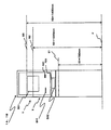
- the space X is a space in which the height (distance in the upward direction (vertical direction)) from the floor surface F is in the range from the first height to the second height.
- the first height is described as H1
- the second height is described as H2.
- H1 and H2 may be the height from the bottom surface of ATM1.
- the range (H1, H2) of space X is demonstrated as what is a height which does not impair operativity and visibility for both a wheelchair user and a wheelchair non-user. is doing.
- a space that only considers operability for example, a range that can be easily reached by a user
- a space that only considers visibility for example, a range that can be easily viewed by a user. Narrow. Therefore, in the first embodiment, when setting H1 and H2 related to the space X, it may be determined in consideration of only operability.
- the surface where the height from the floor surface F is H1 is illustrated as “S1”.
- a surface whose height from the floor surface F is H2 (where H2> H1) is illustrated as “S2”. That is, in FIG. 1, it can be said that the space X is a space between the surface S1 and the surface S2.
- H1 is preferably 750 mm or more and H2 is 1200 mm or less (however, H2> H1).
- the space X is desirably set to a space whose height from the floor surface F is in the range of 750 mm to 1200 mm.
- ATM1 the components of the medium handling port, the display unit, and the input unit are arranged within a space X that has a predetermined range height that does not impair operability for both wheelchair users and wheelchair non-users. ing.
- ATM1 provides convenience (operability for both wheelchair users and non-wheelchair users) without arranging a plurality of operation units (input unit and display unit) as disclosed in JP-A-05-08511. And visibility) can be increased.
- the number of ATMs that can be used increases, which improves convenience.
- FIG. 4 is a front view of the ATM 1A of the second embodiment.
- the difference between the ATM 1A of the second embodiment and the first embodiment will be described.
- the second embodiment is different from the first embodiment in that the control unit 10 (transaction processing unit 101) is replaced with a control unit 10A (transaction processing unit 101A).
- the card insertion / discharge port 401, the touch panel display 501, the pin pad 502, the receipt discharge port 601, and the banknote deposit / withdrawal port 701 are all disposed within the space X.
- the ATM 2 of the second embodiment only a part of the touch panel display 501 that functions as a display unit and an input unit protrudes outside the space X. In other words, in the second embodiment, only part of the touch panel display 501 is located within the space X.
- an object such as a software button (software key) for accepting an input from the user (hereinafter referred to as “input object”). Is configured to be displayed within the space X.
- the screen area of the touch panel display 501 will be described by dividing it into a first area located within the space X and a second area protruding from the space X.
- control unit 10A When the control unit 10A (transaction processing unit 101A) generates an operation screen, the control unit 10A (transaction processing unit 101A) displays an object that does not involve input from the user (for example, a field for displaying information such as a message display or an input amount) Only objects and the like; hereinafter referred to as “display objects”) are arranged. That is, when the control unit 10A (transaction processing unit 101A) generates the operation screen, only the display object is displayed on the entire touch panel display 501 (both the first region and the second region described above). It is possible to arrange.
- display objects Only objects and the like; hereinafter referred to as “display objects”. That is, when the control unit 10A (transaction processing unit 101A) generates the operation screen, only the display object is displayed on the entire touch panel display 501 (both the first region and the second region described above). It is possible to arrange.
- space Y a space that does not impair visibility at least for both wheelchair users and non-wheelchair users.
- the space Y is a space in which the height from the floor surface F is not less than the third height and not more than the fourth height.
- the third height is described as H1
- the fourth height is described as H3 (where H3> H2> H1).
- the lower limit height of the space Y (the above-described third height) is the same height H1 as that of the space X, but the lower limit height H1 of the space X (the above-described first height). The height may be different from the height.
- H3 the surface where the height from the floor surface F is H3 is illustrated as “S3”. That is, in FIG. 4, it can be said that the space Y is a space between the surface S1 and the surface S3. Then, considering the visibility of wheelchair non-users and wheelchair users (for example, the position where the displayed contents can be easily viewed), H2 is 1400 mm or less (however, H3> H2> H1). It is desirable.
- FIG. 5 is a flowchart showing an operation example when a transfer transaction is performed in ATM1A.
- control unit 10A displays a transaction process selection screen (hereinafter referred to as “transaction selection screen”) as shown in FIG. 6 on the touch panel display 501 of the operation display unit 50 (S103). ).
- buttons B101 to B106 in FIG. 6 that can accept an operation (pressing) from the user are within the range of the space X ( It will be arranged below the surface S2.
- a button B101 (a button labeled “withdrawal”) is a withdrawal to be withdrawn from the user's account (for example, an account corresponding to a cash card inserted into the card reader / writer 40). It is a button for starting a gold transaction.
- a button B102 (a button labeled “deposit”) is a button for starting a deposit transaction for depositing (depositing) the account of the user.
- the button B103 (button displayed as “transfer”) is a button for starting a transfer transaction for accepting an inter-account transfer to an account other than the user's account.
- buttons B104 (button displayed as “Balance inquiry”) is a button for starting acceptance of the balance inquiry of the user's account.
- a button B105 (button displayed as “change encryption number”) is a button for starting an encryption number change process for accepting a change of a password corresponding to the cash card of the account.
- the button B106 (button displayed as “use guidance”) is a button for starting display processing of guidance (guide) information related to the use of the ATM 1A.
- the control unit 10A (transaction processing unit 101A) accepts an input of a personal identification number on the operation display unit 50 (hereinafter referred to as a password). , which is referred to as a “password input acceptance screen”) (S104).
- FIG. 7 is an explanatory diagram showing a configuration example of a personal identification number input acceptance screen displayed on the operation display unit 50 by the control unit 10 of the ATM 1A.
- a soft keypad K201 for entering a personal identification number and a transaction stop button B201 are input within the space X (downward from the plane S2). And a field F201 for displaying the number of digits of the personal identification number.
- the soft keypad K201 includes “0 to 9”, “correction”, and “confirm” input keys (buttons).
- the keys (buttons) of the soft keypad K201 are arranged in a line in the horizontal direction (lateral direction) so that the entire softkeypad K201 is within the range of the space X. To fit in.
- control unit 10 transmits the personal identification number to the personal identification number (authentication processing) (S105). ).
- control unit 10A (transaction processing unit 101A) inputs the account number of the user's account acquired from the data recording medium (magnetic stripe, IC chip, etc.) of the cash card and the user.
- the personal identification number is transmitted to the host computer 2 to request verification with the personal identification number held on the host computer 2 side.
- the password check by the host computer 2 is OK (successful authentication).
- the control unit 10 may request the user to input the personal identification number again or cancel the transaction.
- control unit 10A transaction processing unit 101A accepts an input of the withdrawal amount on the operation display unit 50 (hereinafter referred to as “withdrawal amount input acceptance screen”). Is displayed) (S106).
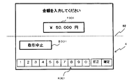
- FIG. 8 is an explanatory diagram showing a configuration example of the withdrawal amount input acceptance screen.
- a soft keypad K301 for entering the withdrawal amount and a transaction stop button B301 are entered within the space X (downward from the plane S2). Has been placed.
- the soft keypad K301 includes input keys (buttons) “0 to 9”, “correction”, and “confirmation”.
- a field F301 for displaying the input transfer amount is arranged in an area outside the range of the space X.
- control unit 10A (transaction processing unit 101A) requests the host computer 2 to perform transaction processing for the transfer transaction by communication, and the processing result (the requested transaction processing is successful). (S107).
- the control unit 10A discharges the receipt from the receipt printer 60 (receipt discharge port 601), discharges the cash card from the card reader / writer 40 (card insertion discharge port 401), and The cash discharge from the cash processing unit 70 (banknote deposit / withdrawal port 701) (banknote ejection according to the withdrawal amount) is controlled (S108).
- control unit 10A causes the operation display unit 50 to display a screen (hereinafter referred to as “transaction end screen”) indicating that the transaction has been established (S109), and this transaction. The process ends.
- the touch panel display 501 is arranged at a position straddling the upper surface S2 of the space X.
- the input object is arranged only in the first area located within the space X, and the display object is arranged in both the first area and the second area outside the space X. It is possible to do.
- the object for a display can be arrange
- visibility can be improved for non-wheelchair users who are taller than the average.
- FIGS. 2 to 4 A functional configuration, a perspective view, and a front view of an ATM 1B of the third embodiment are also shown in FIGS. 2 to 4 as in the second embodiment. be able to.
- the difference between the ATM 1B of the third embodiment and the second embodiment will be described.
- the third embodiment is different from the second embodiment in that the control unit 10A (transaction processing unit 101A) is replaced with a control unit 10B (transaction processing unit 101B).
- And control part 10B (transaction processing part 101B) is in one of two operation modes of the wheelchair user mode for making a wheelchair user operate, and the wheelchair non-user mode for making a wheelchair non-user operate. Operate.
- the input object for receiving the input from the user on the operation screen displayed on the touch panel display 501 is basically in the range of the space X. In the first region.
- control unit 10B displays the input object on the operation screen displayed on the touch panel display 501 within the space X (first region).
- the position is not limited to (inner), and may be any position.
- each operation screen displayed by the control unit 10B is provided with a button for switching the operation mode (hereinafter referred to as “operation mode switching button”), and the operation mode switching button.
- operation mode switching button a button for switching the operation mode
- the wheelchair non-user mode is selected. Transition to. Further, when the operation mode switching button on the operation screen displayed on the touch panel display 501 is pressed while the control unit 10B (transaction processing unit 101B) is operating in the wheelchair non-user mode, the wheelchair user mode is selected. Transition to.
- FIG. 10 is a configuration example of a transaction selection screen displayed on the touch panel display 501 when the control unit 10B (transaction processing unit 101B) operates in the wheelchair non-user mode.
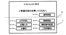
- FIG. 11 is a configuration example of a transaction selection screen displayed on the touch panel display 501 when the control unit 10B (transaction processing unit 101B) operates in the wheelchair user mode. 10 and 11, the same or corresponding reference numerals are assigned to the same or corresponding parts as those in the transaction selection screen (the above-described FIG. 6) of the first embodiment.
- buttons (B101 to B106) corresponding to each transaction are displayed in the space X. It is also placed outside the range.
- an operation mode switching button B107 button displayed as “for wheelchair” for switching the control unit 10B (transaction processing unit 101B) to the wheelchair user mode is displayed in the space X. Arranged within the range.
- each operation screen in the wheelchair non-user mode is basically an operation screen for wheelchair non-users
- the position of the input object should be given priority to visibility and operability for wheelchair non-users. It may be outside the range of X.
- the operation mode switching button is a button for wheelchair users, and therefore needs to be arranged within the space X.
- control unit 10B switches to the wheelchair user mode.
- control part 10B displays the transaction selection screen of the wheelchair user mode shown in FIG.
- control unit 10B operates in the wheelchair user mode unless the operation mode switching button is pressed again in the current transaction.
- the operation of the control unit 10B (transaction processing unit 101B) when the operation mode switching button is pressed on another operation screen of the wheelchair non-user mode is the same.
- the transaction selection screen in the wheelchair user mode shown in FIG. 11 has substantially the same configuration as the screen in the first embodiment (see FIG. 6 described above), but the operation mode switching button B108 (“normal screen” is displayed). Button) is additionally arranged.
- control unit 10B switches to the wheelchair non-user mode.
- control part 10B displays the transaction selection screen of the wheelchair non-user mode shown in FIG.
- control unit 10B operates in the wheelchair non-user mode unless the operation mode switching button is pressed again in the current transaction.
- the operation of the control unit 10B (transaction processing unit 101B) when the operation mode switching button is pressed on another operation screen of the wheelchair user mode is the same.
- Each operation screen in the wheelchair user mode is basically an operation screen for wheelchair users. Therefore, in principle, the position of the input object should be set in the space X with priority given to the visibility and operability of the wheelchair user. Must be within range. However, the operation mode switching button may be arranged outside the space X even in the wheelchair user mode operation screen.
- FIG. 12 is a configuration example of a password input reception screen displayed on the touch panel display 501 when the control unit 10B (transaction processing unit 101B) operates in the wheelchair non-user mode.
- FIG. 13 is a configuration example of a password input reception screen displayed on the touch panel display 501 when the control unit 10B (transaction processing unit 101B) operates in the wheelchair user mode.
- the same or corresponding reference numerals are assigned to the same or corresponding parts as those in the personal identification number input acceptance screen (the above-described FIG. 7) of the first embodiment.
- the soft keypad K201 is placed at a position extending outside the space X in order to give priority to the visibility and operability of the wheelchair user. Yes. Then, on the personal identification number input acceptance screen shown in FIG. 12, the operation mode switching button B202 is arranged within the space X.
- the password input acceptance screen in the wheelchair user mode shown in FIG. 13 has substantially the same configuration as the screen of the first embodiment (see FIG. 7 described above), but an operation mode switching button B202 is additionally arranged. It is different in point.
- FIG. 14 is a configuration example of a withdrawal amount input acceptance screen displayed on the touch panel display 501 when the control unit 10B (transaction processing unit 101B) operates in the wheelchair non-user mode.
- FIG. 15 is a configuration example of a withdrawal amount input acceptance screen displayed on the touch panel display 501 when the control unit 10B (transaction processing unit 101B) operates in the wheelchair user mode.
- the same or corresponding reference numerals are given to the same or corresponding parts as the withdrawal amount input acceptance screen (the above-described FIG. 8) of the first embodiment.
- the soft keypad K301 is arranged at a position straddling the range of the space X, giving priority to the visibility and operability of the wheelchair non-user. Has been.
- the operation mode switching button B302 is disposed within the space X.
- the withdrawal amount input acceptance screen in the wheelchair user mode shown in FIG. 15 has substantially the same configuration as the screen of the first embodiment (see FIG. 8 described above), but an operation mode switching button B303 is additionally arranged. Is different.
- the wheelchair user mode for operating a wheelchair user since it corresponds to two operation modes, the wheelchair user mode for operating a wheelchair user, and the wheelchair non-user mode for operating a wheelchair non-user, each use It is possible to use an operation screen having a layout that is most convenient (operability and visibility) for the user. That is, in the third embodiment, since different screens can be used for wheelchair non-users and wheelchair users, it is not limited to the configuration of the operation screen considering both conveniences. Convenience can be improved compared to the embodiment.
- the transaction apparatus of the present invention is applied to ATM has been described.
- the transaction apparatus may be applied to other transaction apparatuses.
- it is applied to a system for charging (depositing) electronic money into a user's account or a system for selling goods (for example, tickets for transportation etc.) by debiting electronic money from the user's account.
- a system for charging (depositing) electronic money into a user's account or a system for selling goods (for example, tickets for transportation etc.) by debiting electronic money from the user's account.
- Can do
- the transaction apparatus of the present invention is added to the display unit and the input unit (touch panel display 501 and pin pad 502), as well as a medium handling port (receipt printer 60, bill deposit / withdrawal port 701).
- the transaction apparatus of the present invention may be applied to an apparatus that does not have a component that performs medium processing.
- the pin pad is mounted on the ATM, but this may be omitted.
- FIG. 16 shows a configuration in which wheelchair user buttons B111 to B116 corresponding to the buttons B101 to B106 corresponding to each transaction are added to the transaction selection screen for wheelchair non-users in the third embodiment. Yes. Further, in FIG. 16, guide lines are displayed between the buttons B101 to B106 corresponding to each transaction and the buttons B111 to B116 for wheelchair users. With this guide line, the user can intuitively (visually) recognize the correspondence between the buttons B101 to B106 corresponding to each transaction and B111 to B116.
- the wheelchair user buttons B111 to B116 are arranged in the first region within the space X.
- the buttons B101 to B106 corresponding to each transaction and the wheelchair user buttons B111 to B116 correspond to the same function (the same processing is performed when pressed). It shall be configured. Therefore, by arranging the wheelchair user button and the guide wire as shown in FIG. 16, an operation screen that is highly convenient for both wheelchair non-wheelchair users and wheelchair users is realized while utilizing the conventional operation screen. can do.
- the hardware buttons HB101 to HB106 may be replaced. Therefore, by arranging the wheelchair user button and the guide wire as shown in FIG. 17, an operation screen that is highly convenient for both wheelchair non-wheelchair users and wheelchair users is realized while utilizing the conventional operation screen. can do.
- buttons for wheelchair users hardware buttons it is highly convenient for both wheelchair users and wheelchair users without changing the screen layout for displaying the buttons for wheelchair users. An operation screen can be realized.
Landscapes
- Business, Economics & Management (AREA)
- Physics & Mathematics (AREA)
- General Physics & Mathematics (AREA)
- Accounting & Taxation (AREA)
- Finance (AREA)
- Strategic Management (AREA)
- General Business, Economics & Management (AREA)
- Engineering & Computer Science (AREA)
- Theoretical Computer Science (AREA)
- Financial Or Insurance-Related Operations Such As Payment And Settlement (AREA)
Abstract
低コストで、車椅子利用者及び車椅子非利用者の両方にとっての利便性の高い取引装置を提供する。本発明は、取引装置に関する。そして、取引装置は、利用者からの入力を受付ける入力部を有する入力部を備え、利用者の位置する床面からの高さが、車椅子利用者及び車椅子非利用者の利便性を考慮した所定範囲内となる空間内に、一部又は全部が含まれるように、入力部を構成する入力部が配置されている取引装置。
Description
本発明は、取引装置に関し、例えば、銀行などの金融機関やコンビニエンスストアなどに設置されるATM(Automated Teller Machine)に適用し得る。
従来、車椅子利用者と、車椅子を利用しない車椅子非利用者(健常者)との両方の利便性(操作性及び視認性)を考慮したATMとして、特開平05-081511号公報に記載のATMがある。
特開平05-081511号公報に記載されたATMでは、車椅子非利用者の利便性を考慮した高さに配置された第1の操作部と、車椅子利用者の利便性を考慮した高さに配置された第2の操作部とを別個に設ける構成となっている。
しかしながら、特開平05-081511号公報に記載のATMでは、複数の操作部を設ける必要があるため、装置構築コストが多くなってしまうという問題がある。
また、特開平05-081511号公報に記載のATMでは、複数の操作部が配置されているため、利用者がどちらの操作部を利用するべきか直感的に分からず、利用者の利便性に支障が生じる恐れがあった。
そのため、低コストで、車椅子利用者及び車椅子非利用者の両方にとって利便性の高い取引装置が望まれている。
本発明は、利用者からの入力を受付ける入力部を有する取引装置であって、前記利用者の位置する床面からの高さが、車椅子利用者及び車椅子非利用者の利便性を考慮した第1の高さ以上第2の高さ以下の範囲内となる第1の空間内に、一部又は全部が含まれるように、前記入力部が配置されている、取引装置を提供する。
本発明によれば、低コストで、車椅子利用者及び車椅子非利用者の両方にとっての利便性の高い取引装置を提供することができる。
(A)第1の実施形態
以下、本発明による取引装置の第1の実施形態を、図面を参照しながら詳述する。この実施形態では、本発明の取引装置を、ATMに適用した例について説明する。
以下、本発明による取引装置の第1の実施形態を、図面を参照しながら詳述する。この実施形態では、本発明の取引装置を、ATMに適用した例について説明する。
(A-1)第1の実施形態の構成及び動作
図2は、第1の実施形態のATM1の機能的構成を示すブロック図である。また、図3は、第1の実施形態のATM1の斜視図である。
図2は、第1の実施形態のATM1の機能的構成を示すブロック図である。また、図3は、第1の実施形態のATM1の斜視図である。
ATM1は、ネットワークを介してホストコンピュータ2と接続し、ホストコンピュータ2と連携して取引処理(例えば、取引に係るトランザクション処理)を実行する。ホストコンピュータ2としては、例えば、既存のATMを用いた取引処理が可能なホストコンピュータを適用することができるため詳しい説明は省略する。
次に、ATM1の機能的構成について説明する。
ATM1は、図2に示すように制御部10、データ記憶部20、通信部30、カードリーダライタ40、操作表示部50、レシート用プリンタ60、及び現金処理部70を有している。なお、図2において、括弧内の符号は、後述する第2、第3の実施形態で用いられる符号である。
制御部10は、ATM1内の各部の動作制御や情報処理を行う機能を担っているものであり、取引処理部101を有している。データ記憶部20は、制御部10が情報処理を行うために必要な各種情報等を格納するデータ記憶部であり、例えば、各種メモリ等により構成することができる。
取引処理部101は、ATM1内の各部の動作制御や情報処理を行って、利用者と取引処理を行う機能を担っている。制御部10(取引処理部101)は、例えば、プロセッサを含むプログラムの実施構成(コンピュータ)に実施形態の取引プログラム(取引処理部101を実現するためのプログラム)等をインストールすることにより実現することができる。上述の取引プログラムは、例えば、データ記憶部20に記憶しておき、ATM1が起動したときに、制御部10が取引プログラムを読み込んで実行するようにしても良い。
通信部30は、ホストコンピュータ2等に接続するためのネットワークインタフェースである。なお、通信部30については、既存のATM等と同様のものを適用することができるため、詳しい説明は省略する。
カードリーダライタ40は、利用者からカード挿入排出口401に挿入されたキャッシュカードのデータ読取等を行う。なお、カードリーダライタ40は、既存のATM等と同様のものを適用することができるため、詳しい説明は省略する。
レシート用プリンタ60は、レシート用紙に取引内容を印字して、レシート排出口601から排出する。なお、レシート用プリンタ60自体は、既存のATM等と同様のものを適用することができるため、詳しい説明は省略する。
現金処理部70は、利用者から入金された現金を収納する機能と、ATM1に収納されている現金を利用者に出金する機能を担っている。この実施形態では、現金処理部70は、紙幣入出金口701により紙幣の入出金を行うものとして説明する。なお、現金処理部70は、既存のATM等と同様のものを適用することができるため詳しい説明を省略する。また、この実施形態では、現金処理部70は、紙幣の処理のみを行うものとして説明するが、硬貨の処理を行う構成としてもよいし、硬貨及び紙幣の処理を行う構成としてもよい。
操作表示部50は、利用者への表示出力を行う表示部としての機能、及び、利用者からの入力操作を受付ける入力部としての機能を担っている。操作表示部50が備えるデバイスの種類や数は限定されないが、この実施形態では、タッチパネルディスプレイ501及びピンパッド502(PINPAD)を有しているものとする。タッチパネルディスプレイ501は、表示部及び入力部として機能する。また、ピンパッド502は入力部として機能する。
タッチパネルディスプレイ501は、利用者に操作画面を提示し、利用者への表示出力や、ソフトウェアキー(ディスプレイ上に表示された操作キー)等による利用者からの入力操作受付(メニュー選択や金額入力、番号入力等)を行うことが可能なデバイスである。
ピンパッド502は、複数のハードウェアキーにより、利用者からの入力操作受付を行うことが可能なデバイスである。タッチパネルディスプレイ501は、画面生成部としても機能する制御部10(取引処理部101)の制御に応じた操作画面を表示する。
次に、ATM1における各構成要素の配置について図1を用いて説明する。
ATM1では、取引に係る媒体(例えば、キャッシュカード、現金、レシート等)を取扱う(投入及び又は抜取り)ための「媒体取扱口」、利用者への表示出力を行うための「表示部」、及び、利用者からの入力操作を受付けるための「入力部」の位置が、車椅子を利用しない「車椅子非利用者」(例えば、健常者等)及び車椅子を利用する「車椅子利用者」の両方の利便性(操作性及び視認性)を考慮した位置となっている。言い換えると、ATM1では、媒体取扱口、表示部、及び入力部は、車椅子利用者及び車椅子非利用者の両方にとって、操作性及び視認性が損なわれない空間(以下「空間X」と呼ぶ)の内部に配置されているものとする。
空間Xの位置や大きさの詳細は限定されないが、この実施形態では、ATM1の利用者が当該ATM1を利用する際に位置する床面Fからの高さにより定まるものとする。この実施形態では、空間Xは、床面Fからの高さ(上方向(垂直方向)の距離)が第1の高さ以上第2の高さ以下の範囲内となる空間であるものとする。この実施形態では、上述の第1の高さをH1、上述の第2高さをH2として説明する。
なお、床面Fの高さがATM1の底面と一致する場合には、H1及びH2は、ATM1の底面からの高さとしてもよいことは当然である。
また、上述の通り、この実施形態では、空間Xの範囲(H1、H2)は、車椅子利用者及び車椅子非利用者の両方にとって、操作性及び視認性が損なわれない高さであるものとして説明している。しかし、通常、操作性のみを考慮した空間(例えば、利用者が容易に手の届く範囲)は、視認性のみを考慮した空間(例えば、利用者が容易に視認することができる範囲)よりも狭くなる。したがって、第1の実施形態において、空間Xに係るH1、H2を設定する際には、操作性のみを考慮して決定するようにしてもよい。
なお、図1では、床面Fからの高さがH1となる面を「S1」と図示している。また、図1では、床面Fからの高さがH2(ただし、H2>H1)となる面を「S2」と図示している。すなわち、図1では、空間Xは、面S1と面S2の間の空間であるともいえる。
車椅子非利用者及び車椅子利用者の両方の操作性及び視認性を考慮すると、H1は750mm以上、H2は1200mm以下(ただし、H2>H1)とすることが望ましい。言い換えると、ATM1において、空間Xは、床面Fからの高さが750mm以上1200mm以下の範囲内の空間に設定されることが望ましい。
(A-2)第1の実施形態の効果
第1の実施形態によれば、以下のような効果を奏することができる。
第1の実施形態によれば、以下のような効果を奏することができる。
ATM1では、媒体取扱口、表示部、及び入力部の構成要素が、車椅子利用者及び車椅子非利用者の両方にとって、操作性が損なわれない所定範囲の高さとなる空間Xの範囲内に配置されている。これにより、ATM1では、特開平05-081511号公報のように、複数の操作部(入力部及び表示部)を配置することなく、車椅子利用者及び車椅子非利用者の両方にとって利便性(操作性及び視認性)を高くすることができる。特に、車椅子利用者にとっては、利用可能なATMが増えることにつながるため、利便性が向上する。
(B)第2の実施形態
以下、本発明による取引装置の第2の実施形態を、図面を参照しながら詳述する。この実施形態では、本発明の取引装置を、ATMに適用した例について説明する。
以下、本発明による取引装置の第2の実施形態を、図面を参照しながら詳述する。この実施形態では、本発明の取引装置を、ATMに適用した例について説明する。
(B-1)第2の実施形態の構成
第2の実施形態のATM1Aの機能的構成及び斜視図についても、第1の実施形態と同様に図2、図3を用いて示すことができる。また、図4は、第2の実施形態のATM1Aの正面図である。以下、第2の実施形態のATM1Aについて、第1の実施形態との差異を説明する。
第2の実施形態のATM1Aの機能的構成及び斜視図についても、第1の実施形態と同様に図2、図3を用いて示すことができる。また、図4は、第2の実施形態のATM1Aの正面図である。以下、第2の実施形態のATM1Aについて、第1の実施形態との差異を説明する。
第2の実施形態では、制御部10(取引処理部101)が、制御部10A(取引処理部101A)に置き換わっている点で、第1の実施形態と異なっている。
第1の実施形態のATM1では、カード挿入排出口401、タッチパネルディスプレイ501、ピンパッド502、レシート排出口601、及び紙幣入出金口701は、すべて空間Xの範囲内に収まるように配置されていた。これに対して第2の実施形態のATM2では、表示部及び入力部として機能するタッチパネルディスプレイ501についてだけ、一部が空間Xの外側の空間にはみ出している。言い換えると、第2の実施形態では、タッチパネルディスプレイ501は、一部だけが空間Xの範囲内に位置している。
そして、制御部10A(取引処理部101A)によりタッチパネルディスプレイ501に表示される各操作画面では、利用者からの入力を受付けるためのソフトウェアボタン(ソフトウェアキー)等のオブジェクト(以下、「入力オブジェクト」と呼ぶ)が、空間Xの範囲内に表示されるように構成されているものとする。
以下では、タッチパネルディスプレイ501の画面の領域を、空間Xの範囲内に位置する第1の領域と、空間Xからはみ出る第2の領域とに分けて説明する。
制御部10A(取引処理部101A)は、操作画面を生成する際に、第2の領域に、利用者からの入力を伴わないオブジェクト(例えば、メッセージ表示や入力金額等の情報表示を行うフィールドのオブジェクト等;以下、「表示用オブジェクト」と呼ぶ)のみを配置するものとする。すなわち、制御部10A(取引処理部101A)は、操作画面を生成する際に、表示用オブジェクトについてだけは、タッチパネルディスプレイ501全体(上述の第1の領域及び第2の領域の両方の領域)に配置することが可能である。
したがって、ATM1Aでは、タッチパネルディスプレイ501の上側の端が、車椅子利用者及び車椅子非利用者の両方にとって、少なくとも視認性が損なわれない空間内(以下「空間Y」と呼ぶ)に配置されている必要がある。
空間Yの位置や大きさの詳細は限定されないが、この実施形態では、空間Yは、床面Fからの高さが第3の高さ以上第4の高さ以下となる空間内であるものとする。なお、この実施形態では、上述の第3の高さをH1、上述の第4の高さをH3(ただし、H3>H2>H1)として説明する。また、この実施形態では、空間Yの下限の高さ(上述の第3の高さ)は、空間Xと共通の高さH1としているが、空間Xの下限の高さH1(上述の第1の高さ)とは異なる高さとしてもよい。
なお、図4では、床面Fからの高さがH3となる面を「S3」と図示している。すなわち、図4では、空間Yは、面S1と面S3の間の空間であるともいえる。そして、車椅子非利用者及び車椅子利用者の視認性(例えば、表示内容を容易に視認することができる位置であること)を考慮すると、H2は1400mm以下(ただし、H3>H2>H1)とすることが望ましい。
(B-2)第2の実施形態の動作
次に、以上のような構成を有する第2の実施形態のATM1Aの動作を説明する。
次に、以上のような構成を有する第2の実施形態のATM1Aの動作を説明する。
図5は、ATM1Aで振込取引が行われる場合の動作例について示したフローチャートである。
まず、タッチパネルディスプレイ501に初期画面(例えば、キャッシュカードの挿入を促すメッセージの画面)が表示された状態で、キャッシュカードがカードリーダライタ40(カード挿入排出口401)に挿入されたものする(S101、S102)。
そして、制御部10A(取引処理部101A)は、図6に示すような取引処理の選択画面(以下、「取引選択画面」と呼ぶ)を、操作表示部50のタッチパネルディスプレイ501に表示させる(S103)。
図6に示すように、操作表示部50のタッチパネルディスプレイ501では、利用者からの操作(押下)を受付けることが可能なボタン(図6では、ボタンB101~B106)が、空間Xの範囲内(面S2よりも下方向)に配置されることになる。
図6の取引選択画面において、ボタンB101(「お引き出し」と表示されたボタン)は、当該利用者の口座(例えば、カードリーダライタ40に挿入したキャッシュカードに対応する口座)から出金する出金取引を開始するためのボタンである。また、ボタンB102(「お預入れ」と表示されたボタン)は、当該利用者の口座に入金(預金)する預入取引を開始するためのボタンである。さらに、ボタンB103(「お振込」と表示されたボタン)は、当該利用者の口座以外の他の口座への口座間振込みを受付ける振込取引を開始するためのボタンである。さらにまた、ボタンB104(「残高照会」と表示されたボタン)は、当該利用者の口座の残高照会の受付を開始するためのボタンである。また、ボタンB105(「暗号番号変更」と表示されたボタン)は、当該口座のキャッシュカードに対応する暗証番号の変更を受付ける暗号番号変更処理を開始するためのボタンである。また、ボタンB106(「ご利用案内」と表示されたボタン)は、当該ATM1Aの利用に関する案内(ガイド)情報の表示処理を開始するためのボタンである。
そして、取引選択画面で出金取引を開始するためのボタンB101が押下されると、制御部10A(取引処理部101A)は、操作表示部50に、暗証番号の入力を受付けるための画面(以下、「暗証番号入力受付画面」と呼ぶ)を表示させる(S104)。
図7は、ATM1Aの制御部10が操作表示部50に表示させる暗証番号入力受付画面の構成例について示した説明図である。
図7に示すように、暗証番号入力受付画面では、空間Xの範囲内(面S2よりも下方向)に、暗証番号を入力するためのソフトキーパッドK201と、取引中止ボタンB201と、入力された暗証番号の桁数を表示するためのフィールドF201とが配置されている。ソフトキーパッドK201は、「0~9」、「訂正」、「確定」の入力キー(ボタン)により構成されている。図7に示すように、暗証番号入力受付画面では、ソフトキーパッドK201の各キー(ボタン)を水平方向(横方向)にライン状に並べることにより、ソフトキーパッドK201全体を空間Xの範囲内に収まるようにしている。
暗証番号入力受付画面で、暗証番号が入力されると、制御部10(取引処理制御部1、通信制御部4)は、暗証番号のチェック(認証処理)を、ホストコンピュータ2に依頼する(S105)。
具体的には、制御部10A(取引処理部101A)は、キャッシュカードのデータ記録媒体(磁気ストライプやICチップ等)から取得した当該利用者の口座の口座番号と、当該利用者から入力された暗証番号とを、ホストコンピュータ2に送信して、ホストコンピュータ2側で保持している暗証番号との照合を依頼する。ここでは、ホストコンピュータ2により、暗証番号チェックはOK(認証成功)であったものとする。暗証番号チェックの結果がNG(認証失敗)であった場合には、制御部10は、再度利用者に暗証番号の入力を要求したり、取引を中止するようにしてもよい。
暗証番号のチェックがOK(認証成功)の場合、制御部10A(取引処理部101A)は、操作表示部50に、出金金額の入力を受付けるための画面(以下、「出金金額入力受付画面」と呼ぶ)を表示させる(S106)。
図8は、出金金額入力受付画面の構成例について示した説明図である。
図8に示すように、出金金額入力受付画面では、空間Xの範囲内(面S2よりも下方向)に、出金金額を入力するためのソフトキーパッドK301と、取引中止ボタンB301とが配置されている。ソフトキーパッドK301は、「0~9」、「訂正」、「確定」の入力キー(ボタン)により構成されている。図8に示すように、出金金額入力受付画面では、入力された振込金額を表示するためのフィールドF301は、空間Xの範囲外の領域に配置されている。
そして、利用者により振込金額が入力されると、制御部10A(取引処理部101A)は、通信によりホストコンピュータ2に振込取引のトランザクション処理を依頼し、その処理結果(依頼したトランザクション処理が成功したか否か)を受信する(S107)。
取引が成立した場合、制御部10A(取引処理部101A)は、レシート用プリンタ60(レシート排出口601)からのレシート排出、カードリーダライタ40(カード挿入排出口401)からのキャッシュカード排出、及び、現金処理部70(紙幣入出金口701)からの現金排出(出金金額に応じた紙幣の排出)を制御する(S108)。
そして、制御部10A(取引処理部101A)は、取引が成立した旨を表示する画面(以下、「取引終了画面」と呼ぶ)を、操作表示部50に表示させて(S109)、今回の取引処理を終了する。
図9に示す取引終了画面では、「取引が完了しました。キャッシュカード、現金、明細票をお受け取り下さい。」というメッセージのオブジェクトのみを表示している。
(B-3)第2の実施形態の効果
第2の実施形態によれば、以下のような効果を奏することができる。
第2の実施形態によれば、以下のような効果を奏することができる。
第2の実施形態のATM1Aでは、空間Xの上端の面S2を跨ぐ位置にタッチパネルディスプレイ501を配置している。また、ATM1Aでは、入力オブジェクトについては空間Xの範囲内に位置する第1の領域にのみ配置し、表示用オブジェクトについては第1の領域及び、空間Xの外側の第2の領域の両方に配置することが可能となっている。
これにより、ATM1Aでは、操作性及び視認性の両方を考慮した高さH2の面S2よりも上方向の位置(高さH3の面S3までの位置)に、表示用オブジェクトを配置することができる。これにより、例えば、非車椅子利用者で平均よりも身長の高い利用者にとって、視認性を向上させることができる。
(C)第3の実施形態
以下、本発明による取引装置の第3の実施形態を、図面を参照しながら詳述する。この実施形態では、本発明の取引装置を、ATMに適用した例について説明する。
以下、本発明による取引装置の第3の実施形態を、図面を参照しながら詳述する。この実施形態では、本発明の取引装置を、ATMに適用した例について説明する。
(C-1)第3の実施形態の構成
第3の実施形態のATM1Bの機能的構成、斜視図、及び正面図についても、第2の実施形態と同様に図2~図4を用いて示すことができる。以下、第3の実施形態のATM1Bについて、第2の実施形態との差異を説明する。
第3の実施形態のATM1Bの機能的構成、斜視図、及び正面図についても、第2の実施形態と同様に図2~図4を用いて示すことができる。以下、第3の実施形態のATM1Bについて、第2の実施形態との差異を説明する。
第3の実施形態では、制御部10A(取引処理部101A)が、制御部10B(取引処理部101B)に置き換わっている点で、第2の実施形態と異なっている。
そして、制御部10B(取引処理部101B)は、車椅子利用者に操作させるための車椅子利用者モードと、車椅子非利用者に操作させるための車椅子非利用者モードの2つの動作モードのいずれかで動作する。
制御部10B(取引処理部101B)は、車椅子利用者モードで動作する場合、タッチパネルディスプレイ501に表示する操作画面上で、利用者からの入力を受付けるための入力オブジェクトについて、原則として空間Xの範囲内の第1の領域に配置する。
一方、車椅子非利用者モードで動作する場合、制御部10B(取引処理部101B)は、タッチパネルディスプレイ501に表示する操作画面上で、入力オブジェクトの配置位置は空間Xの範囲内(第1の領域内)に限定されず、任意の位置としてもよいものとする。
制御部10B(取引処理部101B)で動作モードの変更を受付ける方法については限定されない。この実施形態では、制御部10B(取引処理部101B)が表示する各操作画面には、動作モードを切り替えるためのボタン(以下、「動作モード切替ボタン」と呼ぶ)が配置され、動作モード切替ボタンの押下により動作切替が実行されるものとして説明する。
すなわち、制御部10B(取引処理部101B)は、車椅子利用者モードで動作している状態で、タッチパネルディスプレイ501に表示する操作画面上の動作モード切替ボタンが押下されると、車椅子非利用者モードに遷移する。また、制御部10B(取引処理部101B)は、車椅子非利用者モードで動作している状態で、タッチパネルディスプレイ501に表示する操作画面上の動作モード切替ボタンが押下されると、車椅子利用者モードに遷移する。
(C-2)第3の実施形態の動作
次に、以上のような構成を有する第3の実施形態のATM1Bの動作を説明する。
次に、以上のような構成を有する第3の実施形態のATM1Bの動作を説明する。
第3の実施形態のATM1Bの動作についても、第2の実施形態と同様に図5のフローチャートを用いて示すことができる。以下では、第3の実施形態について、第2の実施形態との差異のみを説明する。
第3の実施形態のATM1Bでは、基本的な処理の流れは第1の実施形態と同様であるが、操作画面を表示する際の動作として、車椅子利用者モードと車椅子非利用者モードを切り替える動作を行う点で、第2の実施形態と異なっている。また、ATM1Bでは、取引開始時には、デフォルトで車椅子非利用者モードが適用されるものとする。
[取引選択画面]
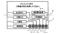
ATM1Bにおいて、上述のステップS103で表示される取引選択画面は、図10、図11のようになる。図10は、制御部10B(取引処理部101B)が、車椅子非利用者モードで動作する場合に、タッチパネルディスプレイ501に表示させる取引選択画面の構成例である。そして、図11は、制御部10B(取引処理部101B)が、車椅子利用者モードで動作する場合に、タッチパネルディスプレイ501に表示させる取引選択画面の構成例である。なお、図10、図11では、第1の実施形態の取引選択画面(上述の図6)と同一又は対応する部分には、同一又は対応する符号を付している。
ATM1Bにおいて、上述のステップS103で表示される取引選択画面は、図10、図11のようになる。図10は、制御部10B(取引処理部101B)が、車椅子非利用者モードで動作する場合に、タッチパネルディスプレイ501に表示させる取引選択画面の構成例である。そして、図11は、制御部10B(取引処理部101B)が、車椅子利用者モードで動作する場合に、タッチパネルディスプレイ501に表示させる取引選択画面の構成例である。なお、図10、図11では、第1の実施形態の取引選択画面(上述の図6)と同一又は対応する部分には、同一又は対応する符号を付している。
図10に示す車椅子非利用者モードの取引選択画面では、車椅子非利用者にとっての利便性(操作性及び視認性)を優先して、各取引に対応するボタン(B101~B106)が、空間Xの範囲外にも配置されている。そして、図10に示す取引選択画面では、制御部10B(取引処理部101B)を車椅子利用者モードに切り替えるための動作モード切替ボタンB107(「車椅子用」と表示されたボタン)が、空間Xの範囲内に配置されている。
車椅子非利用者モードの各操作画面は、基本的に車椅子非利用者向けの操作画面であるので、入力オブジェクトの配置位置は、車椅子非利用者にとっての視認性や操作性を優先して、空間Xの範囲外としてもよい。ただし、車椅子非利用者モードの操作画面であっても、動作モード切替ボタンは車椅子利用者向けのボタンであるので、空間Xの範囲内に配置する必要がある。
そして、図10に示す車椅子非利用者モードの取引選択画面で、動作モード切替ボタンB107が押下されると、制御部10B(取引処理部101B)は、車椅子利用者モードに切り替わる。そして、制御部10B(取引処理部101B)は、図11に示す車椅子利用者モードの取引選択画面をタッチパネルディスプレイ501に表示させる。そして、以後制御部10B(取引処理部101B)は、今回の取引において、再度動作モード切替ボタンが押下されない限り、車椅子利用者モードで動作する。なお、車椅子非利用者モードの他の操作画面で、動作モード切替ボタンが押下された場合における制御部10B(取引処理部101B)の動作は同様である。
図11に示す車椅子利用者モードの取引選択画面は、第1の実施形態の画面(上述の図6参照)とほぼ同様の構成であるが、動作モード切替ボタンB108(「通常画面」と表示されたボタン)が追加配置されている点で異なっている。
そして、図11に示す車椅子利用者モードの取引選択画面で、動作モード切替ボタンB108が押下されると、制御部10B(取引処理部101B)は、車椅子非利用者モードに切り替わる。そして、制御部10B(取引処理部101B)は、図10に示す車椅子非利用者モードの取引選択画面をタッチパネルディスプレイ501に表示させる。そして、以後制御部10B(取引処理部101B)は、今回の取引において、再度動作モード切替ボタンが押下されない限り、車椅子非利用者モードで動作する。なお、車椅子利用者モードの他の操作画面で、動作モード切替ボタンが押下された場合における制御部10B(取引処理部101B)の動作は同様である。
車椅子利用者モードの各操作画面は、基本的に車椅子利用者向けの操作画面であるので、原則として入力オブジェクトの配置位置は、車椅子利用者の視認性や操作性を優先して、空間Xの範囲内とする必要がある。ただし、車椅子利用者モードの操作画面であっても、動作モード切替ボタンは、空間Xの範囲外に配置するようにしてもよい。
[暗証番号入力受付画面]
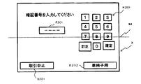
ATM1Bにおいて、上述のステップS104で表示される取引選択画面は、図12、図13のようになる。図12は、制御部10B(取引処理部101B)が、車椅子非利用者モードで動作する場合に、タッチパネルディスプレイ501に表示させる暗証番号入力受付画面の構成例である。そして、図13は、制御部10B(取引処理部101B)が、車椅子利用者モードで動作する場合に、タッチパネルディスプレイ501に表示させる暗証番号入力受付画面の構成例である。なお、図12、図13では、第1の実施形態の暗証番号入力受付画面(上述の図7)と同一又は対応する部分には、同一又は対応する符号を付している。
ATM1Bにおいて、上述のステップS104で表示される取引選択画面は、図12、図13のようになる。図12は、制御部10B(取引処理部101B)が、車椅子非利用者モードで動作する場合に、タッチパネルディスプレイ501に表示させる暗証番号入力受付画面の構成例である。そして、図13は、制御部10B(取引処理部101B)が、車椅子利用者モードで動作する場合に、タッチパネルディスプレイ501に表示させる暗証番号入力受付画面の構成例である。なお、図12、図13では、第1の実施形態の暗証番号入力受付画面(上述の図7)と同一又は対応する部分には、同一又は対応する符号を付している。
図12に示す車椅子非利用者モードの暗証番号入力受付画面では、車椅子利用者の視認性や操作性を優先して、ソフトキーパッドK201が、空間Xの範囲外にまたがった位置に配置されている。そして、図12に示す暗証番号入力受付画面では、動作モード切替ボタンB202が、空間Xの範囲内に配置されている。
図13に示す車椅子利用者モードの暗証番号入力受付画面は、第1の実施形態の画面(上述の図7参照)とほぼ同様の構成であるが、動作モード切替ボタンB202が追加配置されている点で異なっている。
[出金金額入力受付画面]
ATM1Bにおいて、上述のステップS104で表示される取引選択画面は、図14、図15のようになる。図14は、制御部10B(取引処理部101B)が、車椅子非利用者モードで動作する場合に、タッチパネルディスプレイ501に表示させる出金金額入力受付画面の構成例である。そして、図15は、制御部10B(取引処理部101B)が、車椅子利用者モードで動作する場合に、タッチパネルディスプレイ501に表示させる出金金額入力受付画面の構成例である。なお、図14、図15では、第1の実施形態の出金金額入力受付画面(上述の図8)と同一又は対応する部分には、同一又は対応する符号を付している。
ATM1Bにおいて、上述のステップS104で表示される取引選択画面は、図14、図15のようになる。図14は、制御部10B(取引処理部101B)が、車椅子非利用者モードで動作する場合に、タッチパネルディスプレイ501に表示させる出金金額入力受付画面の構成例である。そして、図15は、制御部10B(取引処理部101B)が、車椅子利用者モードで動作する場合に、タッチパネルディスプレイ501に表示させる出金金額入力受付画面の構成例である。なお、図14、図15では、第1の実施形態の出金金額入力受付画面(上述の図8)と同一又は対応する部分には、同一又は対応する符号を付している。
図14に示す車椅子非利用者モードの出金金額入力受付画面では、車椅子非利用者の視認性や操作性を優先して、ソフトキーパッドK301が、空間Xの範囲外にまたがった位置に配置されている。そして、図14に示す出金金額入力受付画面では、動作モード切替ボタンB302が、空間Xの範囲内に配置されている。
図15に示す車椅子利用者モードの出金金額入力受付画面は、第1の実施形態の画面(上述の図8参照)とほぼ同様の構成であるが、動作モード切替ボタンB303が追加配置されている点で異なっている。
(C-3)第3の実施形態の効果
第3の実施形態によれば、第2の実施形態の効果に加えて、さらに以下のような効果を奏することができる。
第3の実施形態によれば、第2の実施形態の効果に加えて、さらに以下のような効果を奏することができる。
第3の実施形態では、車椅子利用者に操作させるための車椅子利用者モードと、車椅子非利用者に操作させるための車椅子非利用者モードの2つの動作モードに対応しているため、それぞれの利用者にとって最も利便性(操作性及び視認性)の高いレイアウトの操作画面を利用することが可能となる。すなわち、第3の実施形態では、車椅子非利用者と車椅子利用者で異なる画面を利用することができるので、両方の利便性を考慮した操作画面の構成とすることに限定されないため、第2の実施形態よりも利便性を向上させることができる。
(D)他の実施形態
本発明は、上記の各実施形態に限定されるものではなく、以下に例示するような変形実施形態も挙げることができる。
本発明は、上記の各実施形態に限定されるものではなく、以下に例示するような変形実施形態も挙げることができる。
(D-1)上記の各実施形態では、本発明の取引装置をATMに適用する例について説明したが、その他の取引装置に適用するようにしても良い。例えば、電子マネー等を利用者の口座にチャージ(入金)する取引や、利用者の口座から電子マネーを引き落として商品(例えば、交通機関等のチケット等)を販売する取引等を行うシステムに適用し得る。
(D-2)上記の各実施形態では、本発明の取引装置を、表示部及び入力部(タッチパネルディスプレイ501、ピンパッド502)に加えて、媒体取扱口(レシート用プリンタ60、紙幣入出金口701)を備えるATMに適用する例について説明したが、本発明の取引装置は、媒体処理を行う構成要素を有さない装置に適用するようにしてもよい。
また、上記の各実施形態では、ATMにピンパッドが搭載されているが、これを省略するようにしてもよい。
(D-3)第2、第3の実施形態では、入力オブジェクトを空間Xの範囲内の第1の領域に配置変更する例について説明したが、例えば、図16の取引選択画面のように、従来の操作画面を構成する各ボタンのそれぞれに対応する車椅子利用者用ボタンを空間Xの範囲内の第1の領域に追加配置し、対応するボタン間を結ぶ線(以下、「誘導線」と呼ぶ)を表示するようにしてもよい。
図16は、第3の実施形態における車椅子非利用者向けの取引選択画面において、各取引に対応するボタンB101~B106のそれぞれに対応する車椅子利用者用ボタンB111~B116を追加した構成となっている。また、図16では、各取引に対応するボタンB101~B106と、車椅子利用者用ボタンB111~B116との間にそれぞれ誘導線が表示されている。この誘導線により、利用者は、各取引に対応するボタンB101~B106と、B111~B116との対応づけを直感的(視覚的)に認識することができる。
そして、車椅子利用者用ボタンB111~B116は、空間Xの範囲内の第1の領域に配置されている。そして、図16に示す取引選択画面では、各取引に対応するボタンB101~B106と、車椅子利用者用ボタンB111~B116とが同じ機能に対応(押下したときに同様の処理を行う)するように構成されているものとする。したがって、図16のように、車椅子利用者用ボタンと誘導線を配置することにより、従来の操作画面を活用しつつ、車椅子非利用者と車椅子利用者の両方にとって利便性の高い操作画面を実現することができる。
また、図17に示すように、図16に示す車椅子利用者用ボタンB111~B116を、タッチパネルディスプレイ501の周囲で空間X内となる位置(図17では、タッチパネルディスプレイ501の下端の部分)に設けたハードウェアボタンHB101~HB106に置き換えるようにしてもよい。したがって、図17のように、車椅子利用者用ボタンと誘導線を配置することにより、従来の操作画面を活用しつつ、車椅子非利用者と車椅子利用者の両方にとって利便性の高い操作画面を実現することができる。また、車椅子利用者用ボタンをハードウェアボタンにすることで、車椅子利用者用ボタンを表示するための画面レイアウトの変更をすることなく、車椅子非利用者と車椅子利用者の両方にとって利便性の高い操作画面を実現することができる。
Claims (10)
- 利用者からの入力を受付ける入力部を有する取引装置であって、
前記利用者の位置する床面からの高さが、車椅子利用者及び車椅子非利用者の利便性を考慮した第1の高さ以上第2の高さ以下の範囲内となる第1の空間内に、一部又は全部が含まれるように、前記入力部が配置されている、
取引装置。 - 前記利用者からの媒体の受入れ、及び又は、前記利用者への媒体の排出を行う媒体取扱口も前記第1の空間内に配置されている、請求項1の取引装置。
- 前記第1の高さは750mmに設定され、さらに、前記第2の高さは1200mmに設定されている、請求項1の取引装置。
- 前記入力部、及び、前記利用者へ表示出力する表示部として、画面生成部を用いて生成した操作画面を、タッチパネルディスプレイを用いて前記利用者に提供する操作画面提供部を備え、
前記タッチパネルディスプレイの第1の領域は前記第1の空間の範囲内に位置しており、
前記画面生成部は、前記タッチパネルディスプレイの前記第1の領域に、利用者からの入力を受付けるための入力オブジェクトを配置した操作画面を生成する、
請求項1~3のいずれかの取引装置。 - 前記タッチパネルディスプレイは、前記利用者の位置する床面からの高さが、車椅子利用者及び車椅子非利用者の視認性のみを考慮した第3の高さ以上第4の高さ以下となる第2の空間内に全部が含まれるように配置されている、請求項4の取引装置。
- 前記画面生成部は、前記第1の領域に入力オブジェクトを配置した操作画面を生成する第1の動作モードと、操作画面を生成する際に入力オブジェクトの位置を限定しない第2の動作モードのいずれかで動作する、請求項5の取引装置。
- 前記画面生成部は、操作画面上に、動作モードの切替えを受付けるための動作切替入力オブジェクトを配置する、請求項6の取引装置。
- 前記画面生成部は、前記第2の動作モードで動作している場合に、少なくとも動作切替入力オブジェクトを前記第1の領域に配置する、請求項7の取引装置。
- 前記入力部、及び、前記利用者へ表示出力する表示部として、画面生成部を用いて生成した操作画面を、タッチパネルディスプレイを用いて前記利用者に提供する操作画面提供部を備え、
前記タッチパネルディスプレイの第1の領域は前記第1の空間の範囲内に位置しており、
前記画面生成部は、前記タッチパネルディスプレイに利用者からの入力を受付けるための入力オブジェクトを配置した操作画面を生成し、
前記画面生成部は、第1のソフトウェアキーと、前記第1のソフトウェアキーと同様の機能に対応したものであって前記第1の領域内に位置する第2のソフトウェアキーとを配置し、前記第1のソフトウェアキーと前記第2のソフトウェアキーとを視覚的に対応付けて表示した操作画面を生成する、
請求項1の取引装置。 - 前記入力部、及び、前記利用者へ表示出力する表示部として、画面生成部を用いて生成した操作画面を、タッチパネルディスプレイを用いて前記利用者に提供する操作画面提供部と、前記タッチパネルディスプレイの周囲で、かつ前記第1の空間内に配置されたハードウェアキーとを備え、
前記画面生成部は、前記タッチパネルディスプレイに利用者からの入力を受付けるためのソフトウェアキーを配置した操作画面を生成し、
前記操作画面提供部は、それぞれの前記ハードウェアキーをいずれかの前記ソフトウェアキーの機能に対応させ、
前記画面生成部は、機能の対応する前記ソフトウェアキーと前記ハードウェアキーとを視覚的に対応付けて表示した操作画面を生成する、
請求項1の取引装置。
Priority Applications (1)
| Application Number | Priority Date | Filing Date | Title |
|---|---|---|---|
| CN201380059302.XA CN104798112B (zh) | 2012-11-22 | 2013-10-08 | 交易装置 |
Applications Claiming Priority (2)
| Application Number | Priority Date | Filing Date | Title |
|---|---|---|---|
| JP2012256688A JP6388466B2 (ja) | 2012-11-22 | 2012-11-22 | 取引装置 |
| JP2012-256688 | 2012-11-22 |
Publications (1)
| Publication Number | Publication Date |
|---|---|
| WO2014080701A1 true WO2014080701A1 (ja) | 2014-05-30 |
Family
ID=50775890
Family Applications (1)
| Application Number | Title | Priority Date | Filing Date |
|---|---|---|---|
| PCT/JP2013/077390 Ceased WO2014080701A1 (ja) | 2012-11-22 | 2013-10-08 | 取引装置 |
Country Status (3)
| Country | Link |
|---|---|
| JP (1) | JP6388466B2 (ja) |
| CN (1) | CN104798112B (ja) |
| WO (1) | WO2014080701A1 (ja) |
Citations (2)
| Publication number | Priority date | Publication date | Assignee | Title |
|---|---|---|---|---|
| JP2009086801A (ja) * | 2007-09-28 | 2009-04-23 | Hitachi Omron Terminal Solutions Corp | 現金自動預入支払機 |
| JP2010204827A (ja) * | 2009-03-02 | 2010-09-16 | Hitachi Omron Terminal Solutions Corp | 現金自動取引装置 |
Family Cites Families (6)
| Publication number | Priority date | Publication date | Assignee | Title |
|---|---|---|---|---|
| JPH0581511A (ja) * | 1991-09-25 | 1993-04-02 | Hitachi Ltd | 現金自動取引装置 |
| GB9714941D0 (en) * | 1997-07-17 | 1997-09-17 | Ncr Int Inc | Self-service terminal |
| JP3680919B2 (ja) * | 1999-06-11 | 2005-08-10 | エヌイーシーコンピュータテクノ株式会社 | 現金自動預金支払機 |
| JP4556526B2 (ja) * | 2004-07-23 | 2010-10-06 | 沖電気工業株式会社 | 現金自動預払機 |
| JP2006133922A (ja) * | 2004-11-04 | 2006-05-25 | Hitachi Omron Terminal Solutions Corp | 自動取引装置の表示方法 |
| JP5056062B2 (ja) * | 2007-02-22 | 2012-10-24 | 沖電気工業株式会社 | 顧客操作型端末装置 |
-
2012
- 2012-11-22 JP JP2012256688A patent/JP6388466B2/ja active Active
-
2013
- 2013-10-08 CN CN201380059302.XA patent/CN104798112B/zh not_active Expired - Fee Related
- 2013-10-08 WO PCT/JP2013/077390 patent/WO2014080701A1/ja not_active Ceased
Patent Citations (2)
| Publication number | Priority date | Publication date | Assignee | Title |
|---|---|---|---|---|
| JP2009086801A (ja) * | 2007-09-28 | 2009-04-23 | Hitachi Omron Terminal Solutions Corp | 現金自動預入支払機 |
| JP2010204827A (ja) * | 2009-03-02 | 2010-09-16 | Hitachi Omron Terminal Solutions Corp | 現金自動取引装置 |
Also Published As
| Publication number | Publication date |
|---|---|
| CN104798112A (zh) | 2015-07-22 |
| CN104798112B (zh) | 2017-10-13 |
| JP2014106555A (ja) | 2014-06-09 |
| JP6388466B2 (ja) | 2018-09-12 |
Similar Documents
| Publication | Publication Date | Title |
|---|---|---|
| JP6811522B2 (ja) | 取引装置 | |
| KR102214283B1 (ko) | 금융 자동화 서비스를 제공하기 위한 방법 및 이를 위한 시스템 | |
| KR101088662B1 (ko) | 자동 거래 장치 및 자동 거래 장치의 이체 처리 방법 | |
| JP6388466B2 (ja) | 取引装置 | |
| JP4807019B2 (ja) | 自動取引システム、自動取引装置、情報管理サーバおよび自動取引方法 | |
| JP4735154B2 (ja) | 自動取引システム、情報管理サーバおよび自動取引装置 | |
| JP2016018441A (ja) | 取引装置 | |
| JP6665959B2 (ja) | 取引装置 | |
| CN101488259A (zh) | 交易处理装置 | |
| JP2014021784A (ja) | 取引装置及びプログラム | |
| JP2007188153A (ja) | 自動取引装置 | |
| JP6064385B2 (ja) | 取引装置 | |
| JP2006099315A (ja) | 自動取引装置 | |
| JP5895725B2 (ja) | 取引装置及びプログラム | |
| JP6194293B2 (ja) | 取引装置及びその取引方法 | |
| KR20120059467A (ko) | 환전 출금 방법 | |
| JP4654002B2 (ja) | 情報表示装置 | |
| JP2003141605A (ja) | Icカード対応の自動取引装置 | |
| JP2011028667A (ja) | 取引処理装置および取引処理システム | |
| JP2005115679A (ja) | 自動取引装置 | |
| JP2011159209A (ja) | 自動取引装置及び自動取引方法 | |
| JP5810885B2 (ja) | 取引装置 | |
| JP2008102775A (ja) | 現金自動取引装置および現金自動取引方法 | |
| JP5708353B2 (ja) | 入力装置及び照合システム | |
| JP2001291140A (ja) | 自動取引装置 |
Legal Events
| Date | Code | Title | Description |
|---|---|---|---|
| 121 | Ep: the epo has been informed by wipo that ep was designated in this application |
Ref document number: 13856170 Country of ref document: EP Kind code of ref document: A1 |
|
| NENP | Non-entry into the national phase |
Ref country code: DE |
|
| 122 | Ep: pct application non-entry in european phase |
Ref document number: 13856170 Country of ref document: EP Kind code of ref document: A1 |