WO2014077190A1 - 運転者用警告装置 - Google Patents
運転者用警告装置 Download PDFInfo
- Publication number
- WO2014077190A1 WO2014077190A1 PCT/JP2013/080196 JP2013080196W WO2014077190A1 WO 2014077190 A1 WO2014077190 A1 WO 2014077190A1 JP 2013080196 W JP2013080196 W JP 2013080196W WO 2014077190 A1 WO2014077190 A1 WO 2014077190A1
- Authority
- WO
- WIPO (PCT)
- Prior art keywords
- driver
- warning
- unit
- camera
- steering wheel
- Prior art date
- Legal status (The legal status is an assumption and is not a legal conclusion. Google has not performed a legal analysis and makes no representation as to the accuracy of the status listed.)
- Ceased
Links
Images









Classifications
-
- G—PHYSICS
- G08—SIGNALLING
- G08B—SIGNALLING SYSTEMS, e.g. PERSONAL CALLING SYSTEMS; ORDER TELEGRAPHS; ALARM SYSTEMS
- G08B21/00—Alarms responsive to a single specified undesired or abnormal condition and not otherwise provided for
- G08B21/02—Alarms for ensuring the safety of persons
- G08B21/06—Alarms for ensuring the safety of persons indicating a condition of sleep, e.g. anti-dozing alarms
-
- B—PERFORMING OPERATIONS; TRANSPORTING
- B60—VEHICLES IN GENERAL
- B60K—ARRANGEMENT OR MOUNTING OF PROPULSION UNITS OR OF TRANSMISSIONS IN VEHICLES; ARRANGEMENT OR MOUNTING OF PLURAL DIVERSE PRIME-MOVERS IN VEHICLES; AUXILIARY DRIVES FOR VEHICLES; INSTRUMENTATION OR DASHBOARDS FOR VEHICLES; ARRANGEMENTS IN CONNECTION WITH COOLING, AIR INTAKE, GAS EXHAUST OR FUEL SUPPLY OF PROPULSION UNITS IN VEHICLES
- B60K28/00—Safety devices for propulsion-unit control, specially adapted for, or arranged in, vehicles, e.g. preventing fuel supply or ignition in the event of potentially dangerous conditions
- B60K28/02—Safety devices for propulsion-unit control, specially adapted for, or arranged in, vehicles, e.g. preventing fuel supply or ignition in the event of potentially dangerous conditions responsive to conditions relating to the driver
- B60K28/06—Safety devices for propulsion-unit control, specially adapted for, or arranged in, vehicles, e.g. preventing fuel supply or ignition in the event of potentially dangerous conditions responsive to conditions relating to the driver responsive to incapacity of driver
- B60K28/066—Safety devices for propulsion-unit control, specially adapted for, or arranged in, vehicles, e.g. preventing fuel supply or ignition in the event of potentially dangerous conditions responsive to conditions relating to the driver responsive to incapacity of driver actuating a signalling device
-
- B—PERFORMING OPERATIONS; TRANSPORTING
- B60—VEHICLES IN GENERAL
- B60W—CONJOINT CONTROL OF VEHICLE SUB-UNITS OF DIFFERENT TYPE OR DIFFERENT FUNCTION; CONTROL SYSTEMS SPECIALLY ADAPTED FOR HYBRID VEHICLES; ROAD VEHICLE DRIVE CONTROL SYSTEMS FOR PURPOSES NOT RELATED TO THE CONTROL OF A PARTICULAR SUB-UNIT
- B60W2420/00—Indexing codes relating to the type of sensors based on the principle of their operation
- B60W2420/40—Photo, light or radio wave sensitive means, e.g. infrared sensors
- B60W2420/403—Image sensing, e.g. optical camera
-
- B—PERFORMING OPERATIONS; TRANSPORTING
- B60—VEHICLES IN GENERAL
- B60W—CONJOINT CONTROL OF VEHICLE SUB-UNITS OF DIFFERENT TYPE OR DIFFERENT FUNCTION; CONTROL SYSTEMS SPECIALLY ADAPTED FOR HYBRID VEHICLES; ROAD VEHICLE DRIVE CONTROL SYSTEMS FOR PURPOSES NOT RELATED TO THE CONTROL OF A PARTICULAR SUB-UNIT
- B60W2540/00—Input parameters relating to occupants
- B60W2540/22—Psychological state; Stress level or workload
Definitions
- the present invention relates to a driver warning device that issues a predetermined warning to a driver so as to perform normal operation when the driver performs a warning target driving such as a drowsy driving or a sideward driving.
- the predetermined determination unit determines that the operation is a warning target for a drowsy driving or a side-viewing operation, and issues a warning (warning sound or vibration) to the driver so as to perform normal driving (For example, see Patent Documents 1 and 2).
- the camera is disposed on the ring portion of the steering wheel, or is disposed on the column cover, and both are fixedly disposed at a predetermined assembly site. It was.
- the present invention solves the above-described problem, and provides a driver warning device that can accurately warn a driver during a warning target operation even if the driver has a difference in physique. With the goal.
- a steering wheel for steering a vehicle having a substantially annular ring portion to be gripped at the time of steering,
- a face detection unit in which a camera capable of photographing a driver's face is disposed in the ring unit;
- a determination unit capable of inputting image data from the camera that has photographed the face and determining a warning target driving of the driver's dozing driving or aside driving;
- a warning generation unit that issues a warning to the driver according to the determination result of the warning target driving in the determination unit;
- a warning device for a driver comprising: The camera is positioned at the center of the front end of the ring part so that the area of the angle of view for the driver can be adjusted up and down, and a rotation axis along the left and right direction is provided to adjust the rotation along the vertical direction. It is characterized by being arranged.
- the warning device for a driver if the camera is rotated around the rotation axis along the left-right direction, in other words, if the direction of the camera (lens) is adjusted up and down, It becomes easy for a driver who steers from the front in the rear to arrange the entire area from the upper part to the lower part of the front of the driver's face or in the area of the camera angle of view around the driver's eyes.
- the face detection unit adjusts the direction of the camera and adjusts the area of the camera's angle of view up and down so that the eyes can be covered. You can shoot accurately, and the camera can accurately capture the movement of the driver's eyes.
- the camera since the camera is arranged at the center of the front end of the ring part and can rotate around the rotation axis along the left-right direction, it can be rotated up and down at an equal distance from the left and right eyes of the driver, From the driver to the small driver, it is possible to accurately capture the movements of the left and right eyes, and to issue a warning reliably and promptly.
- the warning device for a driver even if the driver has a difference in physique, a warning can be accurately issued to the driver during the warning target driving.
- the camera is preferably composed of a plurality of cameras having different angles of view.
- a camera with a wide angle of view can capture the face together with both eyes of the driver, and can detect a drowsy driving or a side-by-side driving, and a camera with a narrow angle of view can display both eyes of the driver as a large image.
- Fine movements of the eyeball can also be detected. Then, from the movement of the eyeball, it is possible to determine what is called an unrealistic driving such as a driving in a state where attention is reduced, and the determination unit can also determine the unrealistic driving as a warning target driving.
- the warning generation unit Vibrating part that is arranged in the ring part so as to be able to come into contact with the driver's hand to be gripped, and vibrates the contact part perceivable to the driver during operation, and the vibration is used as a warning to the driver;
- the steering wheel and the portable terminal include a transmission / reception unit that can wirelessly input and output image data from the camera and an operation signal to the vibration control unit.
- the mobile terminal provided with the determination unit and the warning execution unit can be handled separately. It can. That is, it is not necessary to dispose the components constituting the CPU, ROM, RAM determination unit and warning execution unit such as a predetermined microcomputer for determining the image data on the steering wheel side.
- the present invention can be easily implemented by replacing the steering wheel of an existing vehicle with the steering wheel of the present invention and further preparing the above mobile terminal, for example, a recent display panel, GPS function, etc.
- the warning generation unit warns the driver by giving a perceptible vibration, and the warning due to such vibration is not confused by the driver's field of view or surrounding sounds, The driver can surely perceive and can easily shift to normal driving.
- the warning generation unit is configured to include a sound generation unit that emits a warning sound to the driver during operation.
- the face detection unit is disposed on the steering wheel;
- a mobile terminal separate from the steering wheel is configured to include the determination unit and the warning generation unit, It is desirable that the steering wheel and the mobile terminal are configured to include a transmission / reception unit that can input and output image data from the camera wirelessly.
- the portable terminal provided with the determination unit and the warning generation unit can be handled separately. It can. That is, it is not necessary to dispose components constituting a determination unit and a warning generation unit of a CPU, ROM, and RAM such as a predetermined microcomputer that performs determination processing of image data on the steering wheel side.
- the present invention can be easily implemented by replacing the steering wheel of an existing vehicle with the steering wheel of the present invention and further preparing the above mobile terminal, for example, a recent display panel, GPS function, etc. Install an application that enables the above-mentioned determination unit and warning generation unit to operate on a high-performance tablet or smartphone that has, and then simply replace the steering wheel of the existing vehicle with the steering wheel of the present invention.
- the present invention can be easily implemented.
- the sound generation means of the warning generation unit is to warn the driver by issuing a warning sound
- the portable terminal often has a built-in speaker that can be used as the sound generation means.
- a warning sound can be easily generated, and the driver warning device can be configured more simply than in the case where the warning is given to the driver by vibration.
- the portable terminal is configured to include a communication unit that transmits a determination result of the warning target driving to a receiver outside the vehicle when the determination unit determines the warning target driving. It is desirable that
- an e-mail is sent to a recipient outside the vehicle, for example, an operation manager if the vehicle is a shared bus or a sightseeing bus, or a family member if the vehicle is a private car.
- a recipient outside the vehicle for example, an operation manager if the vehicle is a shared bus or a sightseeing bus, or a family member if the vehicle is a private car.
- the communication means, etc. it is possible to notify the judgment result of the warning target driving, and the receiver can share the information of reflection points and caution points at the time of driving with the driver, which is useful for the subsequent measures. be able to.
- the constituent devices of the driver warning device mounted on the steering wheel side are arranged in common with a horn switch mechanism mounted on the steering wheel. It is desirable that
- the power source of the face detection unit and the like can be secured from the power supply circuit of the horn switch mechanism, and when the driver operates the horn switch, the driver is not in a state of performing the warning target driving. On the contrary, if the driver is driving for the warning, it is not in a state of operating the horn switch, so it is difficult to cause trouble even if the power source is shared, and the horn switch mechanism and the driver warning device are smoothly Can be appropriately operated.
- an illumination unit capable of irradiating infrared rays to the area of the driver's face photographed by the camera is disposed, You may comprise the said camera so that infrared imaging
- FIG. 2 is a partially enlarged longitudinal sectional view of the steering wheel of the first embodiment, corresponding to the II-II portion of FIG. 1 and also showing a state in which the camera is rotated. It is a schematic explanatory drawing explaining the state which adjusts the camera of 1st Embodiment and adjusts the direction of an angle of view. It is a schematic fragmentary sectional view which shows the vibration part of the steering wheel of 1st Embodiment. It is a schematic explanatory drawing which shows the control system of the warning device for drivers
- a driver warning device M1 includes a face detection unit 30 and a warning generation unit 40 as shown in FIGS.
- the steering wheel 10 and the control device 50 are provided.
- the control device 50 includes a mobile terminal 51 such as a smartphone or a tablet having a GPS function capable of calculating the speed of the vehicle.
- the face detection unit 30 includes a camera 33 for photographing the face F of the driver D (see FIG. 3).
- the camera 33 is a digital camera using an image sensor such as a CCD or CMOS having about 300,000 pixels, and has an angle of view (vertical angle of view) of about 50 ° of a standard lens type.
- the image data of the camera 33 is converted into a compressed file format such as Motion JPEG by a predetermined control circuit of the face detection unit 30 and is input to the transmission / reception unit 65 of the steering wheel 10.
- the camera 33 appropriately captures the face F of the driver D facing the steering wheel 10 within the area of the field angle ⁇ ⁇ b> 1 of the camera 33, even if there is a physical difference.
- the center 11fc of the front end of the ring part 11 it is disposed so as to be adjustable in the vertical direction.
- the camera 33 (lens 33a) is arranged on the center line O in the horizontal direction of the steering wheel 10 at the front end center 11fc of the ring portion 11 so that the direction of the lens 33a of the camera 33 can be adjusted up and down. It is installed.
- FIGS. 1 and 2 while providing a straight central shaft portion 12 a extending in the left-right direction at the front end of the cored bar 12 of the ring portion 11 in a state where the vehicle is traveling straight ahead, A concave portion 14 not provided with the covering layer 13 of the ring portion 11 is provided, and a base 31 holding the camera 33 is disposed around the central shaft portion 12 a so as to be rotatable in the vertical direction.
- a cover 32 is provided, and the camera 33 is arranged so as to be adjustable in the vertical direction with the central shaft portion 12a as the rotation axis C.
- the image data output and power harness 36 of the camera 33 is inserted into the metal core 12 through the opening 12b, guided to the vicinity of the spoke portion 20 of the steering wheel 10, and connected to the power supply circuit and the transmission / reception unit 65.
- the detector 30 is connected to a control circuit (not shown).
- the position of the camera 33 that has been rotationally adjusted can be stopped by the frictional resistance with respect to the central shaft portion 12a of the base 31.
- the transmission / reception unit 65, the face detection unit 30, the warning generation unit 40, and the like which are components on the steering wheel 10 side, have their power supply circuits on the steering wheel 10 side of the horn switch mechanism as in a third embodiment to be described later.
- the horn switch mechanism and the power supply are shared.
- the direction of the camera 33 is slightly upward, and in the small driver DS, the direction of the camera 33 is slightly downward compared to the large driver DM.
- the area of the angle of view ⁇ 1 of the camera 33 can be arranged in the range of the face F of the driver D (DM, DS), and the face F is displayed on the display panel 53 in a large size. can do.
- the vertical angle adjustment range of the camera 33 is about 30 °.
- the warning generation unit 40 emits a vibration of the vibrating body 42 of the vibration unit 41 as a warning, and includes a vibration unit 41 and a vibration control unit 48 that controls the operation of the vibration unit 41.
- the vibration part 41 is arranged on the ring part 11 so as to be able to come into contact with the hand H of the driver D to be gripped, and vibrates the vibrating body 42 as a contact part that comes into contact with the hand H so as to be perceivable by the driver D during operation.
- three vibrating portions 41 are disposed on the outer peripheral surface side of the left and right spoke portions 20 (20L, 20R) in the ring portion 11.
- Each vibrating portion 41 is configured by attaching a vibrating body 42 made of synthetic resin having a cap shape (cuboid shape) to a cushion 45 made of rubber or the like fixed to the core metal 12 and a vibration motor 43 attached thereto.
- the vibration motor 43 is configured by attaching an eccentric weight 44 to a rotation drive shaft 43a, and the vibrating body 42 vibrates by the rotation of the rotation drive shaft 43a.
- the vibration control unit 48 inputs an operation signal from the warning execution unit 58 of the portable terminal 51 (control device 50) and operates the vibration motor 43 of each vibration unit 41.
- a harness extending from each vibration motor 43. 46 is connected to a predetermined power supply circuit and a transmission / reception unit 65.
- the vibration control unit 48 can adjust the current value to each vibration motor 43 and can change the frequency of each vibration motor 43 to a large or small value. It is configured to be adjustable to a weak vibration for alarm and a strong vibration for alarm.
- the steering wheel 10 operates the warning generator 40 at the time of operation so that the driver D can voluntarily stop the operation of the warning generator 40.
- An operation switch (answer switch, cancel switch) 27 that can output a stop signal is provided on the portable terminal 51 side.
- the operation switch 27 is disposed in the vicinity of the ring portion 11 of the spoke portion 20 (20L, 20R) as a push button type that can be performed by a pressing operation of the driver D.
- the control device 50 including the mobile terminal 51 inputs the image data of the face F of the driver D from the face detection unit 30 disposed on the steering wheel 10 and controls the operation of the warning generation unit 40. It has. That is, the control unit 55 includes a determination unit 57, a warning execution unit 58, a transmission / reception unit 66 for inputting / outputting wireless data on the steering wheel 10 side, a communication unit 60 as communication means for transmitting an e-mail at a predetermined time, The GPS mechanism described above or an image display mechanism for displaying a predetermined image on the display panel 53 is provided.
- the control unit 55 including the various determination units 57 and the warning execution unit 58 is constituted by a microcomputer having a predetermined CPU, RAM, and ROM.
- the determination unit 57 extracts image data in the vicinity of the left and right eyes E (EL, ER) of the driver D from the image data from the face detection unit 30 based on a program stored in the ROM.
- the program stored in the above-described ROM is configured by application software for driver warning processing separately installed on the mobile terminal 51 so that the mobile terminal 51 can operate as the driver warning device M1. Yes.
- the warning execution part 58 will operate
- the warning execution unit 58 is controlled in consideration of the elapsed time by the timer, the input of the operation ON signal of the operation switch 27, the calculated value of the vehicle speed by detecting the acceleration of the GPS function, and the like.
- An operation ON signal for starting the operation of the generation unit 40, an operation OFF signal for stopping the operation, and a vibration strength signal of the vibration level of each vibration unit 41 are transmitted via the transmission / reception units 66 and 65 to the warning generation unit 40. To control the output.
- step S101 the driver D takes the portable terminal 51 and sits on the driver's seat and activates the driver warning device M1.
- the operation unit 52 is operated to activate the driver warning processing application of the portable terminal 51, and the ignition key of the vehicle is turned on.
- step S102 if the vertical direction of the camera 33 is adjusted so that the entire face F of the driver D is displayed on the display panel 53, the control unit 55 monitors the driver D and gives a warning. The issued driver warning process will be started.
- step S103 the determination unit 57 of the control unit 55 determines whether the driver D is looking aside or closed from the image data near the left and right eyes E (EL, ER) of the driver D from the face detection unit 30. It is detected and it is determined whether the driver is looking aside or drowsy.
- step S104 determines that the driver is in a dangerous driving state during the aside driving or napping.
- the vehicle speed calculated from the acceleration data that can be measured by the GPS function is, for example, 15 km or more (or 30 km or more), If the vehicle speed is 15 km or more, the control unit 55 proceeds to step S105.
- step S105 the control unit 55 determines whether or not a predetermined time, for example, 1 second has elapsed after the determination result of the determination unit 57 as a side-by-side driving or a snoozing operation.
- the unit 58 outputs a weak vibration activation ON signal for alerting to the vibration control unit 48 of the warning generation unit 40 (see step S106, A in FIG. 7).
- step S107 if there is an operation ON signal of the operation switch 27 in step S107, the control unit 55 outputs an operation OFF signal from the warning execution unit 58 to the vibration control unit 48 of the warning generation unit 40 based on the operation ON signal. Thus, the operation of the vibration motor 43 is stopped (see step S108). In step S107, if there is no operation ON signal of the operation switch 27, the process proceeds to step S109.
- step S109 the control unit 55 determines whether or not a predetermined time X, for example, 3 seconds has elapsed after the determination result of the determination unit 57 as a side-by-side driving or a dozing operation, and if it has elapsed, a warning is given.
- the execution unit 58 outputs a strong vibration activation ON signal for warning to the vibration control unit 48 of the warning generation unit 40 (see step S110, B in FIG. 7).
- step S111 if there is an operation ON signal for the operation switch 27 in step S111, the control unit 55 outputs an operation OFF signal from the warning execution unit 58 to the vibration control unit 48 of the warning generation unit 40 based on the operation ON signal. Thus, the operation of the vibration motor 43 is stopped (see step S112). In step S111, if there is no operation ON signal of the operation switch 27, the process proceeds to step S113.
- step S113 the control unit 55 determines whether or not a predetermined time Y, for example, 4 seconds has elapsed after the determination result of the determination unit 57 as a side-by-side driving or a snoozing operation.
- the communication data such as character data including images and positions where the driver D is driving dangerously from the unit 60 is transmitted to a predetermined recipient by e-mail (see step S114), and the driver D is warned.
- the control unit 55 determines the result of the side-by-side driving or dozing operation in the determination unit 57, the determination date / time, the determination position, the determination image, the presence / absence of the operation ON signal of the operation switch 27, and the operation date / time of the operation switch 27.
- the transmission date and time of the communication unit 60 is stored in a predetermined storage area, and the stored data can be displayed on the display panel 53 during a predetermined operation.
- the warning generation unit 40 continues to operate even after the warning process for the driver D is completed through step S115.
- the control unit 55 for example, 30 seconds elapses after a predetermined time elapses. Thereafter, an operation OFF signal may be output from the alarm execution unit 58 to the vibration control unit 48 of the alarm generation unit 40, or the alarm generation unit 40 is continuously operated until there is an operation ON signal of the operation switch 27. Also good.
- the control unit 55 detects the operation ON signal via the transmission / reception units 65 and 66, and the control unit 55 generates a warning via the warning execution unit 58.
- the operation switch 27 when the operation switch 27 is operated, when the operation ON signal is transmitted from the transmission / reception unit 65 to the control unit 55 side, the signal is sent to the vibration control unit 48 at the same time. May be configured to directly stop the operation of the vibration unit 41.
- the driver warning device M1 of the first embodiment if the camera 33 is rotated about the rotation axis C along the left-right direction, in other words, the camera 33 (lens 33a). If the direction is adjusted up and down, the entire area from the top to the bottom of the front face of the driver D or the driver D with respect to the driver D (DM, DS) steered in front of the ring portion 11 or the driver D It becomes easy to arrange in the area of the angle of view of the camera 33 around the eye E (EL, ER).
- the orientation of the camera 33 is adjusted, and the area of the angle of view of the camera 33 with respect to the driver D is adjusted up and down so that the eye E can be covered.
- the face F of the driver D can be accurately photographed, and the camera 33 can accurately capture the movement of the eye E of the driver D.
- the camera 33 since the camera 33 is disposed at the front end center 11fc of the ring portion 11 and can rotate around the rotation axis C along the left-right direction, the camera 33 moves vertically from the left and right eyes EL, ER of the driver D at an equal distance. From the large driver DM to the small driver DS, the movement of the left and right binocular EL and ER can be accurately captured, and a warning can be issued reliably and quickly. It becomes.
- the driver warning device M1 of the first embodiment even if the driver D has a difference in physique, a warning can be accurately issued to the driver D during the warning target driving.
- the warning generation unit 40 is disposed on the ring unit 11 so as to be able to contact the hand H of the driver D to be gripped, and can be perceived by the driver D during operation.
- the vibration part 41 which vibrates the contact part (vibrating body 42) and uses the vibration as a warning to the driver D
- the vibration control part 48 which controls the operation of the vibration part 41 are configured.
- the face detection unit 30 and the warning generation unit 40 are disposed on the steering wheel 10.
- the portable terminal 51 separate from the steering wheel 10 sends an operation signal to the vibration control unit 48 so as to operate the vibration unit 41 together with the determination unit 57 based on the determination result of the warning target operation by the determination unit 57.
- a warning execution unit 58 for outputting.
- the steering wheel 10 and the mobile terminal 51 are configured to include transmission / reception units 65 and 66 that can wirelessly input and output image data from the camera 33 and an operation signal to the vibration control unit 48.
- the steering wheel 10 includes the face detection unit 30, the warning generation unit 40, and the wireless transmission / reception unit 65, the determination unit 57 and the warning execution unit.
- the mobile terminal 51 provided with 58 can be handled as a separate body. That is, the steering wheel 10 side is not provided with a CPU, ROM, RAM determination unit 57 such as a predetermined microcomputer for determining image data, or a component (control unit 55) constituting the warning execution unit 58. It will end. In other words, if the steering wheel of an existing vehicle is replaced with the steering wheel 10 of the embodiment, and the portable terminal 51 is prepared, the embodiment can be easily implemented.
- the driver warning processing application that enables the operation of the above-described determination unit 57 and warning execution unit 58 is installed on a high-functional tablet or smartphone having a GPS function, and then the steering wheel of the existing vehicle is implemented.
- the driver warning process performed by the driver warning device M1 of the embodiment can be easily performed only by replacing the steering wheel 10 of the embodiment.
- the warning generation unit 40 gives a warning by giving a perceptible vibration to the driver D, and the warning due to such vibration is confused by the visual field of the driver D and surrounding sounds. Therefore, the driver D can surely perceive and can easily shift to normal driving.
- the steering wheel 10 having the face detection unit 30 and the warning generation unit 40 and the portable terminal 51 having the determination unit 57 and the warning execution unit 58 are used, and signals are input and output wirelessly.
- the camera 33 provided on the steering wheel 10 side may be fixed so that the rotation cannot be adjusted when attention is paid to the viewpoint that it can be easily used in an existing vehicle. That is, in this case, the camera 33 may be either rotatable or fixed, and is simply disposed on the ring portion 11 so as to photograph the face F of the driver D. Just be there.
- the portable terminal 51 serves as a communication unit that transmits a determination result of the warning target driving to the receiver outside the vehicle when the determination unit 57 determines the warning target driving.
- a communication unit 60 capable of transmitting an electronic mail is provided.
- the determination result of the warning target driving can be notified, and the receiver can share information on reflection points and caution points at the time of driving with the driver D. It can be used for countermeasures.
- the number of cameras 33 is one. However, like the driver warning device M2 of the second embodiment shown in FIGS. 8 to 11, the camera as the face detection unit 30A has a different angle of view. And a plurality of (in the embodiment, two) first cameras 33 and second cameras 34, each of which can be vertically adjusted and arranged at the front end center 11 fc of the ring portion 11. Also good.
- the first camera 33 with a wide angle of view ⁇ 1 captures the face F together with both eyes EL and ER of the driver D (on the display panel 53 shown in FIG. 8).
- a drowsy driving or a side-by-side driving can be detected, and the binocular EL and ER of the driver D are captured as a large image by the second camera 34 having a narrow angle of view ⁇ 2, for example, 10 °.
- a camera with a narrow angle of view produces a larger image than a camera with a wide angle of view
- the right screen 53b of the display panel 53 shown in FIG. 8 can detect any movement.
- an unrealistic driving such as a driving with reduced attention
- the determination unit 57 can also determine the unrealistic driving as a warning target driving.
- the second embodiment it is possible to accurately issue a warning to the driver D not only during a drowsy driving or a side look driving but also during a rough driving that becomes a dangerous driving.
- the camera 34 with a narrow angle of view is disposed close to and symmetrical with the camera 33 at the front end center 11fc of the ring portion 11, and is rotated up and down respectively. It is arranged so that it can be adjusted dynamically.
- the image data of the cameras 33 and 34 is converted into a predetermined file format by a control circuit (not shown) of the face detection unit 30 as in the first embodiment, and WiFi or the like is transmitted from the transmission / reception unit 65 of the steering wheel 10A.
- WiFi or the like is transmitted from the transmission / reception unit 65 of the steering wheel 10A.
- warning processing is performed by the determination unit 57 and the warning execution unit 58 of the control unit 55 of the portable terminal 51 as in the first embodiment. That is, in step S103A of FIG. 11, the determination unit 57 of the control unit 55 determines that the driver D looks aside or closes his eyes from the image data near the left and right eyes E (EL, ER) of the driver D from the face detection unit 30.
- step S103A determination result of the random driving
- step S109A elapsed time from the determination result
- step S113A the state of the random driving is compared to the first embodiment. All that is added is the same as in the first embodiment.
- the first camera 33 with a wide angle of view and the second camera 34 with a narrow angle of view are juxtaposed along the axial direction of the rotation axis C, and the two cameras 33 and 34 are arranged.
- the ring portions 11 are arranged close to each other so as to be arranged at the front end center 11fc, and are arranged so as to be adjustable in the vertical direction.
- the two cameras 33 and 34 are arranged at the center 11fc of the front end of the ring portion 11, as shown in FIG. Good.
- the cameras 33 and 34 may be arranged so as to be adjustable in the vertical direction even when they are arranged side by side in the vertical direction.
- vibrations that can be perceived by the hand H are used as warnings issued to the driver D.
- the warning bosses are provided with central bosses of the steering wheels 10 and 10A so as to visually warn them.
- a lighting means for a lamp such as an LED may be provided near the portion 25 or the spoke portion 20, and the lighting of the lighting means may be used as a warning.
- a sound generating means such as a buzzer or a speaker capable of generating a warning sound is arranged near the boss portion 25 or the spoke portion 20 near the center of the steering wheel 10 or 10A as a warning generating portion so as to give an audible warning. It is good also as a warning by the sound by a sound generation means.
- a warning sound may be generated from the vehicle speaker. Further, as in the driver warning device M3 of the third embodiment shown in FIGS. 13 to 17, the steering wheel 10B side or the vehicle speaker may be used. Alternatively, a warning sound may be generated from the mobile terminal (smartphone) 51B side.
- the face detection unit 30B includes a camera 33B that can photograph the driver's face, and the ring unit 11.
- the rotation axis C is provided along the left-right direction, and is arranged so as to be adjustable in the vertical direction.
- the camera 33B enables infrared photographing, and an illumination unit 38 provided with infrared LEDs 38a and 38a for irradiating the driver's face with infrared rays is disposed around the camera 33B.
- the illumination unit 38 is held and disposed on a base 31B that holds the camera 33B so as to be rotatable about a rotation axis C. Therefore, the illumination unit 38 is arranged so that it can be rotated and adjusted integrally in the vertical direction when adjusting the orientation of the camera 33B.
- an operation switch 27 for stopping the warning sound is disposed on the boss portion 25 in the vicinity of the spoke portion 20R that is easy for the driver D to operate.
- a transmission / reception unit (transmission unit) 65 is provided for transmitting the image data captured by the camera 33B to the transmission / reception unit (reception unit) 66 on the portable terminal 51B side wirelessly in a wireless LAN format such as WiFi. ing.
- the image data captured by the camera 33B is converted into a compressed file format such as Motion JPEG by a predetermined control circuit of the face detection unit 30B, as in the first embodiment, and transmitted / received from the transmission / reception unit 65 to the portable terminal 51B side. Is transmitted to the unit 66.
- a compressed file format such as Motion JPEG
- the transmission / reception unit 65, the face detection unit 30B, and the illumination unit 38 which are the components 80 of the driver warning device M3 on the steering wheel 10B side, have a power switch 82 as shown in FIG.
- the horn switch mechanism 91 and the power supply 90 are shared by connecting to the power supply circuit 92 of the mechanism 91.
- the horn switch mechanism 91 includes a horn switch 95 disposed on the boss portion 25 on the steering wheel 10B side, a vehicle-side relay switch 94, a horn 93, and the like.
- the power supply 90 is composed of a vehicle battery (24V or 12V).
- the illumination unit 38 since the current always flows on the illumination unit 38 side, including the camera 33B side, the illumination unit 38 turns on the infrared LED 38a regardless of day or night.
- control part 55B provided with the warning generation part 62 is arrange
- the control unit 55B includes a warning generation unit 62, a determination unit 57 similar to that of the first embodiment, a transmission / reception unit 66 that inputs and outputs wireless data on the steering wheel 10B side, and a communication unit that transmits an e-mail at a predetermined time.
- a communication unit 60 a GPS mechanism, an image display mechanism for displaying a predetermined image on the display panel 53, and the like.
- control unit 55B is configured by a microcomputer having a predetermined CPU, RAM, and ROM, and the determination unit 57 is based on a program stored in the ROM.
- Image data in the vicinity of the left and right eyes E (EL, ER) of the driver D is extracted from the image data from the detection unit 30B, analyzed in the work area of the RAM, and exceeds a predetermined threshold value.
- the ratio of the time when the eyes EL and ER are closed becomes longer than usual and it is determined that the driver D is dozing and driving, or the time when the driver's eyes EL and ER are out of the front.
- control unit 55B When it is determined that the ratio is higher than that in normal view from the front and the driver D is driving aside, it is determined to be a warning target driving. Then, the control unit 55B outputs an operation signal for operating the warning generation unit 62 based on the determination result of the determination unit 57.
- the program stored in the ROM described above is configured by application software for driver warning processing installed in advance so that the portable terminal 51B can operate as the driver warning device M3, as in the first embodiment. Has been.
- the warning generating unit 62 is configured to generate a warning sound at the time of operation using a speaker 63 as sound generating means provided in a smartphone as the mobile terminal 51B.
- the warning sound is generated by outputting sound data stored in the ROM to the speaker 63.
- step S101 the driver D sits in the driver's seat while bringing the mobile terminal 51B and activates the driver warning device M3.
- the driver 52 of the portable terminal 51B is activated by operating the operation unit 52, and the ignition key of the vehicle is turned on.
- step S102 if the vertical direction of the camera 33B is adjusted so that the entire face F of the driver D is displayed on the display panel 53, the control unit 55B monitors the driver D and gives a warning. The issued driver warning process will be started.
- step S103 the determination unit 57 of the control unit 55B determines whether the driver D is looking aside or closed from the image data near the left and right eyes E (EL, ER) of the driver D from the face detection unit 30B. It is detected and it is determined whether the driver is looking aside or drowsy.
- step S103 when the determination unit 57 determines that the driver D is driving aside or snoozing, the control unit 55B determines whether the vehicle is turning left or right in step S104A. Judging from changes in position information measured by the function, it is difficult to determine whether the driver is looking aside or driving asleep from the movement of the driver's eyes during a left or right turn. For example, the process proceeds to step S104B to determine whether the vehicle speed is in a dangerous driving state during aside driving or doze driving, and in the case of the embodiment, the vehicle speed calculated from the acceleration data that can be measured by the GPS function Is, for example, 30 km or more, and if the vehicle speed is 30 km or more, the controller 55B proceeds to step S105.
- step S105 the control unit 55B determines whether or not a predetermined time, for example, 1 second has elapsed after the determination result of the determination unit 57 being a side-view driving or dozing operation, and if it has elapsed, a sound is generated.
- An operation ON signal is output to the warning generator 62 (see step S106) so as to generate a warning sound with a small volume for alerting from the speaker 63 as a means (see A in FIG. 17).
- step S107 if there is an operation ON signal of the operation switch 27 in step S107, the control unit 55B outputs an operation OFF signal to the warning generation unit 62 based on the operation ON signal, and stops the warning sound from the speaker 63. (See step S108).
- step S107 if there is no operation ON signal of the operation switch 27, the process proceeds to step S109.
- step S109 the control unit 55B determines whether or not a predetermined time X, for example, 3 seconds has elapsed after the determination result of the determination unit 57 as a side-by-side driving or a snoozing operation.
- An operation ON signal is output to the warning generator 62 so as to generate a warning high-volume warning sound from 63 (see B of FIG. 17) (see step S110).
- step S111 if there is an operation ON signal of the operation switch 27 in step S111, the control unit 55B outputs an operation OFF signal to the warning generation unit 62 based on the operation ON signal, and stops the warning sound from the speaker 63. (See step S112). In step S111, if there is no operation ON signal of the operation switch 27, the process proceeds to step S113.
- step S113 the control unit 55B determines whether or not a predetermined time Y, for example, 4 seconds has elapsed after the determination result of the determination unit 57 as a side-by-side driving or a snoozing operation.
- the communication data such as character data including images and positions where the driver D is driving dangerously from the unit 60 is transmitted to a predetermined recipient by e-mail (see step S114), and the driver D is warned.
- the determination result of the side-by-side driving or the dozing operation in the determination unit 57, the determination date / time, the determination position, the determination image, the presence / absence of the operation ON signal of the operation switch 27, the operation date / time of the operation switch 27 The transmission date and time of the communication unit 60 is stored in a predetermined storage area, and the stored data can be displayed on the display panel 53 during a predetermined operation.
- the warning generation unit 62 continues to operate even after the warning process for the driver D is completed through step S115.
- the control unit 55B for example, 30
- an operation OFF signal may be output to the warning generation unit 62, or the warning generation unit 62 may continue to be operated until there is an operation ON signal of the operation switch 27.
- the camera 33B is rotated around the rotation axis C along the left-right direction, in other words, the camera 33 (lens 33a). If the direction is adjusted up and down, the entire area from the top to the bottom of the front of the face F of the driver D or the eyes E (EL , ER) around the vicinity of the field of view of the camera 33B, and even if there is a difference in the physique of the driver D, with respect to the driver D during the warning target driving, A warning can be issued.
- the steering wheel 10B is provided with the face detection part 30B and the radio
- the portable terminal 51B which provided the determination part 57 and the alert generation part 62 will be shown. Since the vehicle can be handled as a separate body, the driver D who is driving the warning object can be obtained by replacing the steering wheel of the existing vehicle with the steering wheel 10B of the embodiment and further preparing the portable terminal 51B. In contrast, a warning sound can be accurately generated.
- the sound generating means of the warning generating unit 62 issues a warning sound to the driver D to give a warning
- the portable terminal 51B incorporates a speaker 63 that can be used as the sound generating means.
- the warning sound can be easily generated, and the driver warning device M3 can be configured more simply than in the case where the warning is given to the driver D by vibration.
- the portable terminal 51B serves as a communication unit that transmits the determination result of the warning target driving to the receiver outside the vehicle when the determination unit 57 determines the warning target driving. Since it is configured to include a communication unit 60 that can send an e-mail, if it is a recipient outside the vehicle, for example, if the vehicle is a shared bus, a sightseeing bus, etc., the operation manager or if the vehicle is a private car , Family members, etc. can be notified of the judgment result of the warning target driving by using communication means such as e-mail. Information can be shared, which can be used for future countermeasures.
- the component device 80 of the driver warning device M3 mounted on the steering wheel 10B side includes a horn switch mechanism 91 and a power supply 90 mounted on the steering wheel 10B. Shared and arranged.
- the power supply circuit 82 such as the face detection unit 30B can be secured from the power supply circuit 92 of the horn switch mechanism 91, and when the driver D operates the horn switch 95, the driver D On the contrary, if the driver D is performing the warning target driving, not the state in which the warning target driving is being performed, the driver D is not in a state of operating the horn switch 95. It is difficult for trouble to occur, and the horn switch mechanism 91 and the driver warning device M3 can be operated smoothly as appropriate.
- the cameras 33 and 33B provided on the steering wheel 10 and 10B side are not adjustable. It may be fixed. That is, in this case, the cameras 33 and 33B may be either rotatable or fixed, and are simply arranged in the ring portion 11 so that the face F of the driver D can be photographed. It may just be done.
- an illumination unit 38 that can irradiate infrared rays to the area of the face of the driver D photographed by the camera 33B is disposed on the steering wheel 10B side, and the camera 33B is configured to be capable of infrared imaging.
- the illumination unit 38 irradiates infrared rays
- the camera 33B can photograph the face (eye) of the driver D smoothly. Furthermore, since infrared rays are used for photographing, the driver D does not feel the illumination unit 38 dazzling, and cannot interfere with the field of view during driving.
- the cameras 33 and 34 to be used may be those having a sensitivity that enables infrared imaging, and an illumination unit 38 that can emit infrared rays may be provided.
- the illumination unit 38 may be disposed on the base 31B that can rotate while supporting the camera 33B, or the ring unit so that the rotation can be adjusted integrally with the camera 33B. 11, the boss part 25, or the spoke part 20 may be provided with the illumination part 38.
- the illumination unit 38 may be disposed on the ring unit 11, the boss unit 25, or the spoke unit 20.
- the illumination unit 38 is turned on regardless of day or night.
- the illumination unit 38 can be detected using a sensor that can detect a predetermined brightness only when the vicinity of the driver's eyes is dark. 38 may be lit.
- a second camera 34 as in the second embodiment may be provided so as to be able to determine a rough driving.
- step S104A of FIG. even when the driver behaves as a warning target driving, at the time of turning left or right, as in step S104A of FIG.
- the processes of S103, 104A, and 104B may be performed in steps S103 and 104 and steps S103A and 104 of FIGS.
- the core metal 12 of the ring part 11 is exemplified as a pipe, but the metal core 12 of the ring part 11 may have an inverted U-shaped cross section, and so on.
- a pipe member made of metal or resin that passes the harness 36 is disposed inside the inverted U-shaped cross section, and the bases 31 and 31B can be rotated around the core bar at the front end center 11fc.
- the cameras 33, 33B, and 34 may be disposed so as to be adjustable in the vertical direction by separately providing a cylindrical guide to be used.
Landscapes
- Engineering & Computer Science (AREA)
- Emergency Management (AREA)
- Combustion & Propulsion (AREA)
- Transportation (AREA)
- Mechanical Engineering (AREA)
- Business, Economics & Management (AREA)
- Chemical & Material Sciences (AREA)
- Physics & Mathematics (AREA)
- General Physics & Mathematics (AREA)
- Traffic Control Systems (AREA)
- Fittings On The Vehicle Exterior For Carrying Loads, And Devices For Holding Or Mounting Articles (AREA)
- Steering Controls (AREA)
- Emergency Alarm Devices (AREA)
Abstract
操舵時に把持する略円環状のリング部(11)を有した車両の操舵用のステアリングホイール(10)と、運転者の顔を撮影可能なカメラ(33)をリング部(11)に配設させてなる顔検出部(30)と、顔を撮影したカメラからの画像データを入力して、運転者の居眠り運転若しくは脇見運転の警告対象運転を判定可能な判定部(57)と、判定部(57)での警告対象運転の判定結果により、運転者に警告を発する警告発生部(40)と、を備える。カメラ(33)は、運転者に対する画角のエリアを上下に調整可能に、リング部の前端中央(11fc)に配置されるとともに、左右方向に沿った回転軸(C)を設けて、上下方向に沿って回動調整可能に配設されている。
Description
本発明は、運転者が居眠り運転や脇見運転の警告対象運転を行った場合、正常運転を行うように、所定の警告を運転者に発する運転者用警告装置に関する。
従来、この種の運転者用警告装置としては、運転者の顔(特に、眼)を撮影するカメラを利用し、運転者が、所定時間以上、眼を閉じていたり、正面を向いていなかった場合、カメラからの画像データに基づき、所定の判定部が、居眠り運転や脇見運転の警告対象運転と判定し、正常な運転を行うように、運転者に警告(警告音や振動)を発するものがあった(例えば、特許文献1,2参照)。
しかし、従来装置では、カメラが、ステアリングホイールのリング部に配設されていたり、あるいは、コラムカバーに配設されており、そして、いずれも、所定の組付部位に固定して配設されていた。
そのため、運転者が大柄、小柄の種々の体格としている場合、的確に、運転者の顔、特に、眼を精度良く検出する点に改善の余地があった。
本発明は、上述の課題を解決するものであり、運転者に体格の差があっても、警告対象運転時の運転者に対して、的確に、警告できる運転者用警告装置を提供することを目的とする。
本発明に係る運転者用警告装置では、操舵時に把持する略円環状のリング部を有した車両の操舵用のステアリングホイールと、
運転者の顔を撮影可能なカメラを前記リング部に配設させてなる顔検出部と、
顔を撮影した前記カメラからの画像データを入力して、運転者の居眠り運転若しくは脇見運転の警告対象運転を判定可能な判定部と、
該判定部での警告対象運転の判定結果により、運転者に警告を発する警告発生部と、
を備えてなる運転者用警告装置であって、
前記カメラが、運転者に対する画角のエリアを上下に調整可能に、前記リング部の前端中央に配置されるとともに、左右方向に沿った回転軸を設けて、上下方向に沿って回動調整可能に配設されていることを特徴とする。
運転者の顔を撮影可能なカメラを前記リング部に配設させてなる顔検出部と、
顔を撮影した前記カメラからの画像データを入力して、運転者の居眠り運転若しくは脇見運転の警告対象運転を判定可能な判定部と、
該判定部での警告対象運転の判定結果により、運転者に警告を発する警告発生部と、
を備えてなる運転者用警告装置であって、
前記カメラが、運転者に対する画角のエリアを上下に調整可能に、前記リング部の前端中央に配置されるとともに、左右方向に沿った回転軸を設けて、上下方向に沿って回動調整可能に配設されていることを特徴とする。
本発明に係る運転者用警告装置では、カメラを左右方向に沿った回転軸の回りで、回動させれば、換言すれば、カメラ(レンズ)の向きを上下に調整すれば、リング部の後方正面で操舵する運転者に対し、運転者の顔の正面の上部から下部までの全域を、あるいは、運転者の眼付近を中心に、カメラの画角のエリア内に配置させ易くなる。
その結果、運転席に着座する際、カメラの向きを調整して、眼をカバーできるように運転者に対するカメラの画角のエリアを上下に調整すれば、顔検出部が、運転者の顔を的確に撮影でき、そして、カメラが運転者の眼の動きを的確に捉えることができる。
特に、カメラは、リング部の前端中央に配置されて、左右方向に沿った回転軸の周りで回転できることから、運転者の左右の眼から均等な距離で、上下に回動できて、大柄な運転者から小柄の運転者まで、的確に、左右の両眼の動きを捉えることができ、確実、かつ、迅速に、警告を発することが可能となる。
したがって、本発明に係る運転者用警告装置では、運転者に体格の差があっても、警告対象運転時の運転者に対して、的確に、警告を発することができる。
本発明に係る運転者用警告装置では、前記カメラが、画角を異ならせた複数のカメラから構成されることが望ましい。
このような構成では、画角の広いカメラで、運転者の両眼とともに顔を捉えて、居眠り運転や脇見運転を検出でき、画角の狭いカメラで、大きな画像として、運転者の両眼を捉えることができて(画素数が同じであれば画角の広いカメラより画角の狭いカメラの方が、大きな画像となる)、眼球の微細な動きも検出できる。そして、眼球の動きからは、考え事をして、注意力が低下した状態の運転等、所謂、漫然運転を判定することができ、判定部において、漫然運転も警告対象運転として、判定できる。
その結果、このような構成では、居眠り運転や脇見運転のみならず、危険運転となる漫然運転時にも、的確に、運転者に警告を発することが可能となる。
本発明に係る運転者用警告装置では、前記警告発生部が、
把持する運転者の手に接触可能に前記リング部に配置され、作動時、運転者に知覚可能に接触部位を振動させて、該振動を運転者への警告とする振動部と、
前記振動部の作動を制御する振動制御部と、
を備えて構成され、
前記顔検出部と前記警告発生部とが、前記ステアリングホイールに配設され、
前記ステアリングホイールと別体とした携帯端末が、前記判定部とともに、前記判定部による警告対象運転の判定結果に基づいて、前記振動部を作動させるように前記振動制御部に作動信号を出力する警告実行部と、を備えて構成され、
前記ステアリングホイール及び前記携帯端末が、前記カメラからの画像データと前記振動制御部への作動信号との入出力を無線で行い可能な送受信部を備えて構成されていることが望ましい。
把持する運転者の手に接触可能に前記リング部に配置され、作動時、運転者に知覚可能に接触部位を振動させて、該振動を運転者への警告とする振動部と、
前記振動部の作動を制御する振動制御部と、
を備えて構成され、
前記顔検出部と前記警告発生部とが、前記ステアリングホイールに配設され、
前記ステアリングホイールと別体とした携帯端末が、前記判定部とともに、前記判定部による警告対象運転の判定結果に基づいて、前記振動部を作動させるように前記振動制御部に作動信号を出力する警告実行部と、を備えて構成され、
前記ステアリングホイール及び前記携帯端末が、前記カメラからの画像データと前記振動制御部への作動信号との入出力を無線で行い可能な送受信部を備えて構成されていることが望ましい。
このような構成では、ステアリングホイールが、顔検出部、警告発生部、及び、無線の送受信部を備えていれば、判定部や警告実行部を設けた携帯端末を、別体として、取り扱うことができる。すなわち、ステアリングホイール側には、画像データを判定処理する所定のマイクロコンピュータ等のCPU,ROM,RAMの判定部や警告実行部を構成する部品を、配設せずにすむ。換言すれば、既存の車両のステアリングホイールを、本発明のステアリングホイールと交換し、さらに、上記の携帯端末さえ準備すれば、本発明を簡便に実施でき、例えば、昨今の表示パネルやGPS機能等を有した高機能のタブレットやスマートフォンに、既述の判定部や警告実行部の動作を可能とするアプリケーションをインストールし、後は、既存車両のステアリングホイールを本発明のステアリングホイールと交換するだけで、本発明を容易に実施することも可能となる。
さらに、上記の構成では、警告発生部が、運転者に知覚可能な振動を与えて警告するものであり、このような振動による警告は、運転者の視野や周囲の音に惑わされること無く、運転者が確実に知覚できて、容易に正常運転に移行できる。
本発明に係る運転者用警告装置では、前記警告発生部が、作動時、運転者に対して警告音を発する音発生手段を備えて構成され、
前記顔検出部が、前記ステアリングホイールに配設され、
前記ステアリングホイールと別体とした携帯端末が、前記判定部と前記警告発生部とを備えて構成され、
前記ステアリングホイール及び前記携帯端末が、前記カメラからの画像データの入出力を無線で行い可能に送受信部を備えて構成されていることが望ましい。
前記顔検出部が、前記ステアリングホイールに配設され、
前記ステアリングホイールと別体とした携帯端末が、前記判定部と前記警告発生部とを備えて構成され、
前記ステアリングホイール及び前記携帯端末が、前記カメラからの画像データの入出力を無線で行い可能に送受信部を備えて構成されていることが望ましい。
このような構成では、ステアリングホイールが、顔検出部、及び、無線の送受信部(送信部)を備えていれば、判定部や警告発生部を設けた携帯端末を、別体として、取り扱うことができる。すなわち、ステアリングホイール側には、画像データを判定処理する所定のマイクロコンピュータ等のCPU,ROM,RAMの判定部や警告発生部を構成する部品を、配設せずにすむ。換言すれば、既存の車両のステアリングホイールを、本発明のステアリングホイールと交換し、さらに、上記の携帯端末さえ準備すれば、本発明を簡便に実施でき、例えば、昨今の表示パネルやGPS機能等を有した高機能のタブレットやスマートフォンに、既述の判定部や警告発生部の動作を可能とするアプリケーションをインストールし、後は、既存車両のステアリングホイールを本発明のステアリングホイールと交換するだけで、本発明を容易に実施することも可能となる。
さらに、上記の構成では、警告発生部の音発生手段が、運転者に警告音を発して警告するものであって、携帯端末は、音発生手段として利用できるスピーカを内蔵させている場合が多く、容易に警告音を発生させることができて、運転者への警告を振動により行う場合に比べて、より簡便に運転者用警告装置を構成できる。
本発明に係る運転者用警告装置では、前記携帯端末が、前記判定部での警告対象運転の判定時、車外の受信者に警告対象運転の判定結果を発信する通信手段、を備えて構成されていることが望ましい。
このような構成では、車外の受信者、例えば、車両が乗合バスや観光バス等であれば、運行責任者、あるいは、車両が自家用車であれば、家族の者等、に対して、電子メール等の通信手段を利用して、警告対象運転の判定結果を通知できて、受信者が、運転者とともに、運転時の反省点や注意点の情報を共有することができ、以後の対策に役立てることができる。
本発明に係る運転者用警告装置では、前記ステアリングホイール側に搭載される前記運転者用警告装置の構成機器が、前記ステアリングホイールに搭載されるホーンスイッチ機構と電源を共用して、配設されていることが望ましい。
このような構成では、顔検出部等の電源をホーンスイッチ機構の電源回路から確保でき、そして、ホーンスイッチを運転者が操作する際には、運転者は警告対象運転を行っている状態でなく、逆に、運転者が警告対象運転を行っていれば、ホーンスイッチを操作する状態でもないことから、電源を共用しても支障が生じ難く、円滑にホーンスイッチ機構と運転者用警告装置とを適宜作動させることができる。
本発明に係る運転者用警告装置では、前記ステアリングホイール側に、前記カメラの撮影する運転者の顔のエリアに赤外線を照射可能な照明部を、配設するとともに、
前記カメラを、赤外線撮影を可能に構成してもよい。
前記カメラを、赤外線撮影を可能に構成してもよい。
このような構成では、夜間やトンネル内の走行時、あるいは、サングラスを装着して走行し、運転者の顔や眼の辺り暗くなっても、照明部によって赤外線を照射すれば、カメラが円滑に運転者の顔(眼)を撮影することができる。さらに、撮影に赤外線を利用していることから、運転者は、照明部を眩しく感ずることなく、運転中の視界を妨げられない。
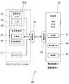
以下、本発明の一実施形態を図面に基づいて説明すると、第1実施形態の運転者用警告装置M1は、図1,5に示すように、顔検出部30と警告発生部40とを設けたステアリングホイール10と、制御装置50と、を備えて構成されている。制御装置50は、車両の速度を算出可能なGPS機能を具備したスマートフォンやタブレット等の携帯端末51から構成されている。
顔検出部30は、運転者Dの顔F(図3参照)を撮影するためのカメラ33を備えて構成されている。カメラ33は、30万画素程度のCCDやCMOS等の撮像素子を使用したデジタルカメラであり、画角(垂直画角)を標準レンズタイプの約50°としている。
そして、実施形態の場合、カメラ33の画像データは、顔検出部30の所定の制御回路により、MotionJPEG等の圧縮ファイル形式とされて、ステアリングホイール10の送受信部65に入力され、そして、送受信部65から、WiFi等の無線LAN形式等の無線で、携帯端末51側の送受信部66へ送信され、そして、携帯端末51側で展開され、展開された画像データは、後述する判定部57に入力されるとともに、携帯端末51の表示パネル53に表示されることとなる。
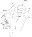
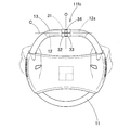
また、カメラ33は、図1,3に示すように、ステアリングホイール10に正対する運転者Dの顔Fを、体格差があっても、撮影するカメラ33の画角θ1のエリア内に、適切に配置されるように、リング部11の前端中央11fcにおいて、上下方向に回動調整可能に配設されている。換言すれば、カメラ33のレンズ33aの向きを上下に調整可能に、リング部11の前端中央11fcにおけるステアリングホイール10の左右方向の中央の中心線O上に、カメラ33(レンズ33a)は、配設されている。
具体的には、図1,2に示すように、車両の直進操舵時の状態におけるリング部11の芯金12の前端に、左右方向に沿って延びる直線状の中心軸部12aを設けつつ、リング部11の被覆層13を設けない凹部14を設け、中心軸部12aの周囲に、カメラ33を保持するベース31を、上下方向に回動可能に配設し、さらに、ベース31の周囲にカバー32を設けて、カメラ33が、中心軸部12aを回転軸Cとして、上下方向に回動調整可能とするように、配設されている。カメラ33の画像データの出力用や電源用のハーネス36は、開口12bから芯金12内に挿入され、ステアリングホイール10のスポーク部20付近に導かれ、電源回路や送受信部65と接続される顔検出部30の図示しない制御回路に接続されている。
そして、ベース31の中心軸部12aに対する摩擦抵抗により、回動調整したカメラ33は、その位置を停止させることができる。
なお、ステアリングホイール10側の構成機器である送受信部65、顔検出部30、警告発生部40等は、その電源回路を、後述する第3実施形態のように、ホーンスイッチ機構のステアリングホイール10側の電源回路に接続させて、ホーンスイッチ機構と電源を共用している。
また、図3に示すように、大柄な運転者DMでは、カメラ33の向きを若干上向きとし、小柄な運転者DSでは、大柄な運転者DMに比べて、カメラ33の向きを若干下向きとすれば、体格差があっても、運転者D(DM,DS)の顔Fの範囲に、カメラ33の画角θ1のエリアを配置させることができて、表示パネル53に、顔Fを大きく表示することができる。
実施形態の場合、カメラ33の上下方向の角度調整範囲は、約30°としている。
警告発生部40は、振動部41の振動体42の振動を警告として発するもので、振動部41と、振動部41の作動を制御する振動制御部48と、を備えて構成されている。
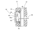
振動部41は、把持する運転者Dの手Hに接触可能にリング部11に配置され、作動時、運転者Dに知覚可能に手Hに接触する接触部位としての振動体42を振動させる。また、振動部41は、実施形態の場合、リング部11における左右のスポーク部20(20L,20R)の外周面側に、3個ずつ配設されている。そして、各振動部41は、キャップ形状(直方体形状)の合成樹脂製の振動体42が、芯金12に固着されたゴム等からなるクッション45に接着されるとともに、振動モータ43を取り付けて構成されている。振動モータ43は、回転駆動軸43aに、偏心錘44を取り付けて構成され、回転駆動軸43aの回転により、振動体42が振動することとなる。
振動制御部48は、携帯端末51(制御装置50)の警告実行部58からの作動信号を入力して、各振動部41の振動モータ43を作動させるものであり、各振動モータ43から延びるハーネス46と結線されるとともに、所定の電源回路や送受信部65と接続されている。また、振動制御部48は、実施形態の場合、各振動モータ43への電流値を調整可能として、各振動モータ43の振動数を大小に変更可能としており、振動体42の振動に関し、注意喚起用の弱振動と警報用の強振動とに調整可能に構成されている。
また、実施形態のステアリングホイール10は、図1,5に示すように、警告発生部40の作動を運転者Dが自発的に停止させることができるように、操作時に、警告発生部40の作動を停止させるように携帯端末51側に停止信号を出力可能な操作スイッチ(アンサースイッチ、キャンセルスイッチ)27が設けられている。操作スイッチ27は、運転者Dの押圧操作で行ない可能な押しボタンタイプとして、スポーク部20(20L,20R)のリング部11近傍に、配設されている。
携帯端末51からなる制御装置50は、ステアリングホイール10に配設された顔検出部30からの運転者Dの顔Fの画像データを入力して、警告発生部40の作動を制御する制御部55を備えている。すなわち、制御部55は、判定部57、警告実行部58、ステアリングホイール10側の無線データの出入力を行う送受信部66、さらに、所定時に電子メールを送信する通信手段としての通信部60、既述のGPS機構、あるいは、表示パネル53に所定の画像を表示する画像表示機構等を具備して、構成されている。
これらの種々の判定部57や警告実行部58を具備する制御部55は、所定のCPU,RAM,ROMを備えたマイクロコンピュータ(マイコン)から構成され、その制御を簡単に述べれば、制御部55の判定部57が、ROMに記憶されたプログラムに基づいて、顔検出部30からの画像データから、運転者Dの左右の眼E(EL,ER)付近の画像データを抽出して、RAMの作業領域で分析し、所定の閾値を越えて、運転者Dの眼EL,ERが閉じている時間の割合が通常時より長くなって運転者Dが居眠り運転をしていると判定したり、あるいは、運転者の眼EL,ERが正面から外れている時間の割合が正面視の通常時より多くなって、運転者Dが脇見運転をしていると判定した際、警告対象運転と判定する。そして、制御部55は、判定部57の判定結果により、警告実行部58から警告発生部40を作動させる作動信号を出力させる。
なお、既述のROMに記憶させるプログラムは、携帯端末51が運転者用警告装置M1として動作できるように、携帯端末51に、別途、インストールした運転者警告処理用のアプリケーションソフトから、構成されている。
そして、制御部55は、警告実行部58に、警告発生部40を作動させる作動信号を出力するように、作動させることとなるが、実施形態では、図6の流れ図に示すように、所定のタイマによる経過時間、操作スイッチ27の操作ON信号の入力、さらに、GPS機能の加速度の検出による車速の算出値等を加味して、警告実行部58を制御することとなり、警告実行部58が警告発生部40の作動を開始させる作動ON信号、作動を停止させる作動OFF信号、さらに、各振動部41の振動の強弱の振動強弱信号等を、送受信部66,65を介して、警告発生部40に出力するように、制御する。
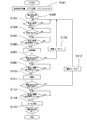
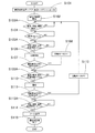
制御部55の制御に関して、詳しく述べれば、図6に示すように、まず、ステップS101では、運転者Dが、携帯端末51を持ち込みつつ、運転席に着座し、運転者用警告装置M1を作動させるように、操作部52を操作して携帯端末51の運転者警告処理アプリを起動させ、また、車両のイグニッションキーをONさせる。ついで、ステップS102において、運転者Dの顔Fの全体が表示パネル53に表示されるように、カメラ33の上下の向きを調整すれば、制御部55は、運転者Dを監視して警告を発する運転者警告処理を開始することとなる。
そして、ステップS103では、制御部55の判定部57が、顔検出部30からの運転者Dの左右の眼E(EL,ER)付近の画像データから、運転者Dが脇見や閉眼の状態を検出し、脇見運転若しくは居眠り運転をしているか否か判定する。
そして、ステップS103において、運転者Dが脇見運転若しくは居眠り運転していると判定部57が判定した場合には、制御部55は、ステップS104において、脇見運転時若しくは居眠り運転時に危険な走行状態となるような車速であるか否かを判定し、実施形態の場合、GPS機能で測定できる加速度データから算出した車速が例えば15km以上(あるいは30km以上としてもよい)であるか否かを判定し、15km以上の車速であれば、制御部55は、ステップS105に移行する。
ステップS105では、制御部55は、判定部57の脇見運転若しくは居眠り運転との判定結果の経過後、所定時間、例えば1秒経過しているか否かを判定し、経過していれば、警告実行部58から警告発生部40の振動制御部48に、注意喚起用の弱振動の作動ON信号を出力する(ステップS106、図7のA参照)。
その後、ステップS107において、操作スイッチ27の操作ON信号があれば、制御部55は、その操作ON信号に基づき、警告実行部58から警告発生部40の振動制御部48に作動OFF信号を出力して、振動モータ43の作動を停止させる(ステップS108参照)。そして、ステップS107において、操作スイッチ27の操作ON信号がなければ、ステップS109に移行する。
ステップS109では、制御部55は、判定部57の脇見運転若しくは居眠り運転との判定結果の経過後、所定時間X、例えば3秒経過しているか否かを判定し、経過していれば、警告実行部58から警告発生部40の振動制御部48に、警報用の強振動の作動ON信号を出力する(ステップS110、図7のB参照)。
その後、ステップS111において、操作スイッチ27の操作ON信号があれば、制御部55は、その操作ON信号に基づき、警告実行部58から警告発生部40の振動制御部48に作動OFF信号を出力して、振動モータ43の作動を停止させる(ステップS112参照)。そして、ステップS111において、操作スイッチ27の操作ON信号がなければ、ステップS113に移行する。
ステップS113では、制御部55は、判定部57の脇見運転若しくは居眠り運転との判定結果の経過後、所定時間Y、例えば4秒経過しているか否かを判定し、経過していれば、通信部60から運転者Dが危険運転している画像や位置等を含んだ文字データ等の通信データを、電子メールにて所定の受信者に発信し(ステップS114参照)、運転者Dへの警告処理を終える(ステップS115参照)。
なお、制御部55は、判定部57での脇見運転や居眠り運転の判定結果、その判定日時、判定位置、判定画像、さらに、操作スイッチ27の操作ON信号の有無、その操作スイッチ27の操作日時、そして、通信部60の発信日時等を、所定の記憶領域に記憶させ、そして、所定の操作時に、それらの記憶したデータを表示パネル53に表示できるように構成されている。
また、実施形態では、ステップS115を経て運転者Dへの警告処理が終了しても、警告発生部40は作動し続けているが、制御部55が、所定時間経過後、例えば、30秒経過後、警告実行部58から警告発生部40の振動制御部48に作動OFF信号を出力してもよいし、あるいは、操作スイッチ27の作動ON信号があるまで、警告発生部40を作動させ続けても良い。
さらに、実施形態では、操作スイッチ27を操作した際、送受信部65,66を経て、制御部55が操作ON信号を検出し、そして、制御部55が、警告実行部58を介して、警告発生部40の作動OFF信号を出力するように構成したが、操作スイッチ27を操作した際、その操作ON信号を送受信部65から制御部55側へ発信する際、同時に、振動制御部48にその信号を入力させて、振動部41の作動を、直接、停止させるように、構成してもよい。
以上のように、第1実施形態の運転者用警告装置M1では、カメラ33を左右方向に沿った回転軸Cの回りで、回動させれば、換言すれば、カメラ33(レンズ33a)の向きを上下に調整すれば、リング部11の後方正面で操舵する運転者D(DM,DS)に対し、運転者Dの顔Fの正面の上部から下部までの全域を、あるいは、運転者Dの眼E(EL,ER)付近を中心に、カメラ33の画角のエリア内に配置させ易くなる。
その結果、運転席に着座する際、カメラ33の向きを調整して、眼Eをカバーできるように運転者Dに対するカメラ33の画角のエリアを上下に調整すれば、顔検出部30が、運転者Dの顔Fを的確に撮影でき、そして、カメラ33が運転者Dの眼Eの動きを的確に捉えることができる。
特に、カメラ33は、リング部11の前端中央11fcに配置されて、左右方向に沿った回転軸Cの周りで回転できることから、運転者Dの左右の眼EL,ERから均等な距離で、上下に回動できて、大柄な運転者DMから小柄の運転者DSまで、的確に、左右の両眼EL,ERの動きを捉えることができ、確実、かつ、迅速に、警告を発することが可能となる。
したがって、第1実施形態の運転者用警告装置M1では、運転者Dに体格の差があっても、警告対象運転時の運転者Dに対して、的確に、警告を発することができる。
また、第1実施形態の運転者用警告装置M1では、警告発生部40が、把持する運転者Dの手Hに接触可能にリング部11に配置され、作動時、運転者Dに知覚可能に接触部位(振動体42)を振動させて、振動を運転者Dへの警告とする振動部41と、振動部41の作動を制御する振動制御部48と、を備えて構成されている。また、顔検出部30と警告発生部40とが、ステアリングホイール10に配設されている。さらに、ステアリングホイール10と別体とした携帯端末51が、判定部57とともに、判定部57による警告対象運転の判定結果に基づいて、振動部41を作動させるように振動制御部48に作動信号を出力する警告実行部58と、を備えて構成されている。そして、ステアリングホイール10及び携帯端末51が、カメラ33からの画像データと振動制御部48への作動信号との入出力を無線で行い可能な送受信部65,66を備えて構成されている。
すなわち、第1実施形態の運転者用警告装置M1では、ステアリングホイール10が、顔検出部30、警告発生部40、及び、無線の送受信部65を備えていれば、判定部57や警告実行部58を設けた携帯端末51を、別体として、取り扱うことができる。すなわち、ステアリングホイール10側には、画像データを判定処理する所定のマイクロコンピュータ等のCPU,ROM,RAMの判定部57や警告実行部58を構成する部品(制御部55)を、配設せずに済む。換言すれば、既存の車両のステアリングホイールを、実施形態のステアリングホイール10と交換し、さらに、上記の携帯端末51さえ準備すれば、実施形態を簡便に実施でき、例えば、昨今の表示パネル53やGPS機能等を有した高機能のタブレットやスマートフォンに、既述の判定部57や警告実行部58の動作を可能とする運転者警告処理アプリをインストールし、後は、既存車両のステアリングホイールを実施形態のステアリングホイール10と交換するだけで、実施形態の運転者用警告装置M1が行う運転者警告処理を容易に実施することも可能となる。
さらに、上記の構成では、警告発生部40が、運転者Dに知覚可能な振動を与えて警告するものであり、このような振動による警告は、運転者Dの視野や周囲の音に惑わされること無く、運転者Dが確実に知覚できて、容易に正常運転に移行できる。
なお、顔検出部30及び警告発生部40を有したステアリングホイール10と、判定部57及び警告実行部58を有した携帯端末51と、の2部品を使用し、相互に無線により信号の入出力を行う構成とした運転者用警告装置では、既存の車両で容易に使用できる観点に着目した場合、ステアリングホイール10側に設けるカメラ33は、回動調整不能として、固定されていてもよい。すなわち、この場合には、カメラ33は、回動可能であっても、固定されていても、どちらでもよく、単に、運転者Dの顔Fを撮影できるようにリング部11に配設されているだけでもよい。
さらに、第1実施形態の運転者用警告装置M1では、携帯端末51が、判定部57での警告対象運転の判定時、車外の受信者に警告対象運転の判定結果を発信する通信手段としての電子メールを送信できる通信部60、を備えて構成されている。
すなわち、第1実施形態では、車外の受信者、例えば、車両が乗合バスや観光バス等であれば、運行責任者、あるいは、車両が自家用車であれば、家族の者等、に対して、電子メール等の通信手段を利用して、警告対象運転の判定結果を通知できて、受信者が、運転者Dとともに、運転時の反省点や注意点の情報を共有することができ、以後の対策に役立てることができる。
なお、第1実施形態では、カメラ33を1つとしたが、図8~11に示す第2実施形態の運転者用警告装置M2のように、顔検出部30Aとしてのカメラを、画角を異ならせた複数(実施形態では2つ)の第1のカメラ33と第2のカメラ34とから構成するとともに、それぞれ、上下に回動調整可能として、リング部11の前端中央11fcに配設させてもよい。
このような構成では、画角の角度θ1の広い、例えば50°とした第1のカメラ33で、運転者Dの両眼EL,ERとともに顔Fを捉えて(図8に示す表示パネル53の左側画面53a参照)、居眠り運転や脇見運転を検出でき、画角の角度θ2の狭い、例えば10°とした第2のカメラ34で、大きな画像として、運転者Dの両眼EL,ERを捉えることができて(画素数が同じであれば画角の広いカメラより画角の狭いカメラの方が、大きな画像となる)(図8に示す表示パネル53の右側画面53b参照)、眼球の微細な動きも検出できる。そして、眼球の動きからは、考え事をして、注意力が低下した状態の運転等、所謂、漫然運転を判定することができ、判定部57において、漫然運転も警告対象運転として、判定できる。
その結果、第2実施形態では、居眠り運転や脇見運転のみならず、危険運転となる漫然運転時にも、的確に、運転者Dに警告を発することが可能となる。
なお、第2実施形態のステアリングホイール10Aでは、画角の狭いカメラ34を、リング部11の前端中央11fcにおいて、カメラ33と左右対称として接近して配設させているとともに、それぞれ、上下に回動調整可能に配設されている。
そして、カメラ33,34の画像データは、第1実施形態と同様に、顔検出部30の図示しない制御回路で、所定のファイル形式に変換されて、ステアリングホイール10Aの送受信部65から、WiFi等の無線形式で、携帯端末51側の送受信部66に送信され、携帯端末51の制御部55の判定部57や警告実行部58により、第1実施形態と同様に、警告処理される。すなわち、図11のステップS103Aにおいて、制御部55の判定部57が、顔検出部30からの運転者Dの左右の眼E(EL,ER)付近の画像データから、運転者Dが脇見あるいは閉眼の状態だけでなく、眼球の微細な動きの有無から漫然運転か否かも判定し、脇見運転、居眠り運転、あるいは、漫然運転をしているか否か判定する。そして、この漫然運転の判定結果(ステップS103A参照)、あるいは、その判定結果からの経過時間(ステップS105A,ステップS109A,ステップS113A参照)に関して、漫然運転の状態が、第1実施形態と比べて、加味されるだけで、後の処理は、第1実施形態と同様となる。
また、第2実施形態では、画角の広い第1のカメラ33と画角の狭い第2のカメラ34とを回転軸Cの軸方向に沿って並設させつつ、二つのカメラ33,34を、リング部11の前端中央11fcに配設させるように相互に接近させ、かつ、それぞれ、上下方向に回動調整可能に配置させた。しかし、二つのカメラ33,34をリング部11の前端中央11fcに配設させる場合、図12に示すように、回転軸C回りで上下方向に回動可能として、上下方向に並設させてもよい。勿論、このように上下方向に並設させる場合でも、各カメラ33,34をそれぞれ上下方向に回動調整可能に配設させてもよい。
さらに、第1,2実施形態では、運転者Dに発する警告として、手Hで知覚可能な振動としているが、警告発生部として、視覚で警告するように、ステアリングホイール10,10Aの中央のボス部25付近やスポーク部20付近に、LED等のランプの点灯手段を配設し、点灯手段の点灯を警告としてもよい。あるいは、警告発生部として、聴覚で警告するように、ステアリングホイール10,10Aの中央のボス部25付近やスポーク部20付近に、警告音を発することができるブザーやスピーカ等の音発生手段を配設し、音発生手段による音を警告としてもよい。
さらにまた、車両のスピーカから警告音を発生させるようにしてもよく、さらに、図13~17に示す第3実施形態の運転者用警告装置M3のように、ステアリングホイール10B側や車両のスピーカで無く、警告音を携帯端末(スマートフォン)51B側から発生させてもよい。
この運転者用警告装置M3では、ステアリングホイール10B側には、第1実施形態の顔検出部30と同様に、顔検出部30Bが、運転者の顔を撮影可能なカメラ33Bを、リング部11の前端中央11fcに配置させるとともに、左右方向に沿った回転軸Cを設けて、上下方向に沿って回動調整可能に配設している。このカメラ33Bは、赤外線撮影を可能にするものであり、カメラ33Bの周囲には、運転者の顔に赤外線を照射する赤外線LED38a,38aを設けてなる照明部38が、配設されている。照明部38は、カメラ33Bを回転軸Cの回りで回動可能に保持するベース31Bに、保持されて配設されている。そのため、照明部38は、カメラ33Bの向きの調整時、一体的に上下方向に沿って回動調整できるように、配設されている。
また、ステアリングホイール10B側には、第1実施形態と同様に、警告音を停止させるための操作スイッチ27が、運転者Dの操作し易いスポーク部20R近傍のボス部25に配設されるとともに、カメラ33Bで撮影した画像データを、WiFi等の無線LAN形式等の無線で、携帯端末51B側の送受信部(受信部)66へ送信するための送受信部(送信部)65が、配設されている。
なお、カメラ33Bにより撮影した画像データは、第1実施形態と同様に、顔検出部30Bの所定の制御回路により、MotionJPEG等の圧縮ファイル形式とされて、送受信部65から携帯端末51B側の送受信部66へ送信される。
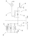
また、ステアリングホイール10B側の運転者用警告装置M3の構成機器80である送受信部65、顔検出部30B、及び、照明部38は、その電源回路82を、図15に示すように、ホーンスイッチ機構91の電源回路92と接続させて、ホーンスイッチ機構91と電源90を共用している。ホーンスイッチ機構91は、ステアリングホイール10B側のボス部25に配設されるホーンスイッチ95、車両側のリレースイッチ94、ホーン93等を備えて構成されている。電源90は、車両用バッテリー(24V若しくは12V)から構成されている。
なお、実施形態の場合、照明部38側には、カメラ33B側も含めて、常時、電流が流れていることから、照明部38は、その赤外線LED38aを昼夜を問わず点灯させている。
そして、第3実施形態では、携帯端末51B側に、警告発生部62を備えてなる制御部55Bが配設されている。制御部55Bは、警告発生部62の他、第1実施形態と同様な判定部57、ステアリングホイール10B側の無線データの出入力を行う送受信部66、さらに、所定時に電子メールを送信する通信手段としての通信部60、GPS機構、あるいは、表示パネル53に所定の画像を表示する画像表示機構等を具備して、構成されている。
また、制御部55Bは、第1実施形態と同様に、所定のCPU,RAM,ROMを備えたマイクロコンピュータ(マイコン)から構成され、判定部57が、ROMに記憶されたプログラムに基づいて、顔検出部30Bからの画像データから、運転者Dの左右の眼E(EL,ER)付近の画像データを抽出して、RAMの作業領域で分析し、所定の閾値を越えて、運転者Dの眼EL,ERが閉じている時間の割合が通常時より長くなって運転者Dが居眠り運転をしていると判定したり、あるいは、運転者の眼EL,ERが正面から外れている時間の割合が正面視の通常時より多くなって、運転者Dが脇見運転をしていると判定した際、警告対象運転と判定する。そして、制御部55Bは、判定部57の判定結果により、警告発生部62を作動させる作動信号を出力する。
なお、既述のROMに記憶させるプログラムは、第1実施形態と同様に、携帯端末51Bが運転者用警告装置M3として動作できるように、予めインストールした運転者警告処理用のアプリケーションソフトにより、構成されている。
また、警告発生部62は、携帯端末51Bとしてのスマートフォンに設けられた音発生手段としてのスピーカ63を利用し、作動時、警告音を発生するように構成されいてる。警告音は、ROMに記憶されている音データをスピーカ63に出力して発生させており、実施形態の場合、図17に示すように、例えば、断続的に、ピ、ピ、ピ…と小音量で警告する警告音と、ピ、ピ、ピ…と大音量で警告する警告音の2種類がある。
制御部55Bの制御を詳しく説明すると、図16に示すように、まず、ステップS101では、運転者Dが、携帯端末51Bを持ち込みつつ、運転席に着座し、運転者用警告装置M3を作動させるように、操作部52を操作して携帯端末51Bの運転者警告処理アプリを起動させ、また、車両のイグニッションキーをONさせる。ついで、ステップS102において、運転者Dの顔Fの全体が表示パネル53に表示されるように、カメラ33Bの上下の向きを調整すれば、制御部55Bは、運転者Dを監視して警告を発する運転者警告処理を開始することとなる。
そして、ステップS103では、制御部55Bの判定部57が、顔検出部30Bからの運転者Dの左右の眼E(EL,ER)付近の画像データから、運転者Dが脇見や閉眼の状態を検出し、脇見運転若しくは居眠り運転をしているか否か判定する。
ステップS103において、運転者Dが脇見運転若しくは居眠り運転していると判定部57が判定した場合には、制御部55Bは、ステップS104Aにおいて、車両が左折中や右折中であるか否かをGPS機能で測定する位置情報の変化から判定して、左折中や右折中では運転者の眼の動きから脇見運転若しくは居眠り運転か否かを判定し難いことから、左折や右折の状態でないと判定すれば、ステップS104Bに移行して、脇見運転時若しくは居眠り運転時に危険な走行状態となるような車速であるか否かを判定し、実施形態の場合、GPS機能で測定できる加速度データから算出した車速が例えば30km以上であるか否かを判定し、30km以上の車速であれば、制御部55Bは、ステップS105に移行する。
ステップS105では、制御部55Bは、判定部57の脇見運転若しくは居眠り運転との判定結果の経過後、所定時間、例えば1秒経過しているか否かを判定し、経過していれば、音発生手段としてのスピーカ63から注意喚起用の小音量の警告音を発生させるように(図17のA参照)、警告発生部62に作動ON信号を出力する(ステップS106参照)。
その後、ステップS107において、操作スイッチ27の操作ON信号があれば、制御部55Bは、その操作ON信号に基づき、警告発生部62に作動OFF信号を出力して、スピーカ63からの警告音を停止させる(ステップS108参照)。そして、ステップS107において、操作スイッチ27の操作ON信号がなければ、ステップS109に移行する。
ステップS109では、制御部55Bは、判定部57の脇見運転若しくは居眠り運転との判定結果の経過後、所定時間X、例えば3秒経過しているか否かを判定し、経過していれば、スピーカ63から警報用の大音量の警告音を発生させるように(図17のB参照)、警告発生部62に作動ON信号を出力する(ステップS110参照)。
その後、ステップS111において、操作スイッチ27の操作ON信号があれば、制御部55Bは、その操作ON信号に基づき、警告発生部62に作動OFF信号を出力して、スピーカ63からの警告音を停止させる(ステップS112参照)。そして、ステップS111において、操作スイッチ27の操作ON信号がなければ、ステップS113に移行する。
ステップS113では、制御部55Bは、判定部57の脇見運転若しくは居眠り運転との判定結果の経過後、所定時間Y、例えば4秒経過しているか否かを判定し、経過していれば、通信部60から運転者Dが危険運転している画像や位置等を含んだ文字データ等の通信データを、電子メールにて所定の受信者に発信し(ステップS114参照)、運転者Dへの警告処理を終える(ステップS115参照)。
なお、制御部55Bでも、判定部57での脇見運転や居眠り運転の判定結果、その判定日時、判定位置、判定画像、さらに、操作スイッチ27の操作ON信号の有無、その操作スイッチ27の操作日時、そして、通信部60の発信日時等を、所定の記憶領域に記憶させ、そして、所定の操作時に、それらの記憶したデータを表示パネル53に表示できるように構成されている。
また、第3実施形態でも、ステップS115を経て運転者Dへの警告処理が終了しても、警告発生部62は作動し続けているが、制御部55Bが、所定時間経過後、例えば、30秒経過後、警告発生部62に作動OFF信号を出力してもよいし、あるいは、操作スイッチ27の作動ON信号があるまで、警告発生部62を作動させ続けても良い。
以上のように、第3実施形態の運転者用警告装置M3でも、カメラ33Bを左右方向に沿った回転軸Cの回りで、回動させれば、換言すれば、カメラ33(レンズ33a)の向きを上下に調整すれば、リング部11の後方正面で操舵する運転者Dに対し、運転者Dの顔Fの正面の上部から下部までの全域を、あるいは、運転者Dの眼E(EL,ER)付近を中心に、カメラ33Bの画角のエリア内に配置させ易くなって、運転者Dに体格の差があっても、警告対象運転時の運転者Dに対して、的確に、警告を発することができる。
そして、第3実施形態でも、ステアリングホイール10Bが、顔検出部30B、及び、無線の送受信部(送信部)65を備えていれば、判定部57や警告発生部62を設けた携帯端末51Bを、別体として、取り扱うことができることから、既存の車両のステアリングホイールを、実施形態のステアリングホイール10Bと交換し、さらに、上記の携帯端末51Bさえ準備すれば、警告対象運転している運転者Dに対して、的確に警告音を発することができる。
さらに、第3実施形態では、警告発生部62の音発生手段が、運転者Dに警告音を発して警告するものであって、携帯端末51Bは、音発生手段として利用できるスピーカ63を内蔵させている場合が多く、容易に警告音を発生させることができて、運転者Dへの警告を振動により行う場合に比べて、より簡便に運転者用警告装置M3を構成できる。
また、第3実施形態の運転者用警告装置M3でも、携帯端末51Bが、判定部57での警告対象運転の判定時、車外の受信者に警告対象運転の判定結果を発信する通信手段としての電子メールを送信できる通信部60、を備えて構成されているため、車外の受信者、例えば、車両が乗合バスや観光バス等であれば、運行責任者、あるいは、車両が自家用車であれば、家族の者等、に対して、電子メール等の通信手段を利用して、警告対象運転の判定結果を通知できて、受信者が、運転者Dとともに、運転時の反省点や注意点の情報を共有することができ、以後の対策に役立てることができる。
また、第3実施形態の運転者用警告装置M3では、ステアリングホイール10B側に搭載される運転者用警告装置M3の構成機器80が、ステアリングホイール10Bに搭載されるホーンスイッチ機構91と電源90を共用して、配設されている。
そのため、第3実施形態では、顔検出部30B等の電源回路82をホーンスイッチ機構91の電源回路92から確保でき、そして、ホーンスイッチ95を運転者Dが操作する際には、運転者Dは警告対象運転を行っている状態でなく、逆に、運転者Dが警告対象運転を行っていれば、運転者Dがホーンスイッチ95を操作する状態でもないことから、電源90を共用しても支障が生じ難く、円滑にホーンスイッチ機構91と運転者用警告装置M3とを適宜作動させることができる。
この運転者警告装置のステアリングホイール側の構成機器の電源を、ホーンスイッチ機構の電源と共用することに着目すれば、ステアリングホイール10,10B側に設けるカメラ33,33Bは、回動調整不能として、固定されていてもよい。すなわち、この場合には、カメラ33,33Bは、回動可能であっても、固定されていても、どちらでもよく、単に、運転者Dの顔Fを撮影できるようにリング部11に配設されているだけでもよい。
さらに、第3実施形態の運転者用警告装置M3では、ステアリングホイール10B側に、カメラ33Bの撮影する運転者Dの顔のエリアに赤外線を照射可能な照明部38を、配設するとともに、カメラ33Bを、赤外線撮影を可能に構成している。
そのため、第3実施形態では、夜間やトンネル内の走行時、あるいは、サングラスを装着して走行し、運転者Dの顔や眼の辺り暗くなっても、照明部38によって赤外線を照射すれば、カメラ33Bが円滑に運転者Dの顔(眼)を撮影することができる。さらに、撮影に赤外線を利用していることから、運転者Dは、照明部38を眩しく感ずることなく、運転中の視界を妨げられない。
なお、第1,2実施形態においても、使用するカメラ33,34として、赤外線撮影を可能にする感度のものを使用し、そして、赤外線を照射できる照明部38を配設してもよい。
その場合、第3実施形態のように、カメラ33Bと一体的に回動調整可能に、照明部38をカメラ33Bを支持して回動可能なベース31Bに配設してもよいし、リング部11やボス部25、あるいは、スポーク部20に照明部38を配設してもよい。勿論、第3実施形態においても、リング部11やボス部25、あるいは、スポーク部20に照明部38を配設してもよい。
また、第3実施形態では、照明部38を昼夜を問わず点灯させているが、運転者の眼の付近が暗い場合にだけ、所定の明るさを検知可能なセンサを利用して、照明部38を点灯させてもよい。
さらに、第3実施形態のステアリングホイール10Bの顔検出部30Bとして、漫然運転を判定できるように、第2実施形態のような二つ目のカメラ34を設けてもよい。
さらにまた、第3実施形態では、運転者が警告対象運転の挙動をしていても、右左折時には、図16のステップS104Aのように、警告対象運転と判定しない構成としており、このようなステップS103,104A,104Bの処理を、第1,2実施形態の図6,11のステップS103,104やステップS103A,104で行ってもよい。
また、第1~3実施形態では、リング部11の芯金12に関して、パイプ状のものを例示したが、リング部11の芯金12は、断面逆U字状等のものもあり、そのような場合には、ハーネス36を通す金属あるいは樹脂からなるパイプ材を断面逆U字状の内側に配設させる等すると共に、前端中央11fcにおいて、芯金周囲にベース31,31Bを回動可能とする円筒状のガイドを別途設ける等して、カメラ33,33B,34を上下方向に回動調整可能に配設すればよい。
10,10A,10B…ステアリングホイール、11…リング部、11fc…前端中央、30,30A,30B…顔検出部、33,33B,34…カメラ、40,62…警告発生部、41…振動部、42…(接触部位)振動体、48…振動制御部、
50,50B…制御装置、51,51B…携帯端末、53…表示パネル、55…制御部、57…判定部、58…警告実行部、60…通信部、
62…(音発生手段)スピーカ、
65,66…送受信部、
80…構成機器、82…(構成機器用の)電源回路、90…車両用電源、91…ホーンスッチ機構、92…(ホーンスイッチ機構の)電源回路、
θ1,θ2…画角、C…回転軸、D(DM,DS)…運転者、F…顔、E(EL,ER)…眼、H…手、M1,M2,M3…運転者用警告装置。
50,50B…制御装置、51,51B…携帯端末、53…表示パネル、55…制御部、57…判定部、58…警告実行部、60…通信部、
62…(音発生手段)スピーカ、
65,66…送受信部、
80…構成機器、82…(構成機器用の)電源回路、90…車両用電源、91…ホーンスッチ機構、92…(ホーンスイッチ機構の)電源回路、
θ1,θ2…画角、C…回転軸、D(DM,DS)…運転者、F…顔、E(EL,ER)…眼、H…手、M1,M2,M3…運転者用警告装置。
Claims (7)
- 操舵時に把持する略円環状のリング部を有した車両の操舵用のステアリングホイールと、
運転者の顔を撮影可能なカメラを前記リング部に配設させてなる顔検出部と、
顔を撮影した前記カメラからの画像データを入力して、運転者の居眠り運転若しくは脇見運転の警告対象運転を判定可能な判定部と、
該判定部での警告対象運転の判定結果により、運転者に警告を発する警告発生部と、
を備えてなる運転者用警告装置であって、
前記カメラが、運転者に対する画角のエリアを上下に調整可能に、前記リング部の前端中央に配置されるとともに、左右方向に沿った回転軸を設けて、上下方向に沿って回動調整可能に配設されていることを特徴とする運転者用警告装置。 - 前記カメラが、画角を異ならせた複数のカメラから構成されていることを特徴とする請求項1に記載の運転者用警告装置。
- 前記警告発生部が、
把持する運転者の手に接触可能に前記リング部に配置され、作動時、運転者に知覚可能に接触部位を振動させて、該振動を運転者への警告とする振動部と、
前記振動部の作動を制御する振動制御部と、
を備えて構成され、
前記顔検出部と前記警告発生部とが、前記ステアリングホイールに配設され、
前記ステアリングホイールと別体とした携帯端末が、前記判定部とともに、前記判定部による警告対象運転の判定結果に基づいて、前記振動部を作動させるように前記振動制御部に作動信号を出力する警告実行部と、を備えて構成され、
前記ステアリングホイール及び前記携帯端末が、前記カメラからの画像データと前記振動制御部への作動信号との入出力を無線で行い可能な送受信部を備えて構成されていることを特徴とする請求項1若しくは請求項2に記載の運転者用警告装置。 - 前記警告発生部が、作動時、運転者に対して警告音を発する音発生手段を備えて構成され、
前記顔検出部が、前記ステアリングホイールに配設され、
前記ステアリングホイールと別体とした携帯端末が、前記判定部と前記警告発生部とを備えて構成され、
前記ステアリングホイール及び前記携帯端末が、前記カメラからの画像データの入出力を無線で行い可能に送受信部を備えて構成されていることを特徴とする請求項1若しくは請求項2に記載の運転者用警告装置。 - 前記携帯端末が、前記判定部での警告対象運転の判定時、車外の受信者に警告対象運転の判定結果を発信する通信手段、を備えて構成されていることを特徴とする請求項3若しくは請求項4に記載の運転者用警告装置。
- 前記ステアリングホイール側に搭載される前記運転者用警告装置の構成機器が、前記ステアリングホイールに搭載されるホーンスイッチ機構と電源を共用して、配設されていることを特徴とする請求項1乃至請求項5のいずれか1項に記載の運転者用警告装置。
- 前記ステアリングホイール側に、前記カメラの撮影する運転者の顔のエリアに赤外線を照射可能な照明部が、配設されるとともに、
前記カメラが、赤外線撮影を可能に構成されていることを特徴とする請求項1乃至請求項6のいずれか1項に記載の運転者用警告装置。
Applications Claiming Priority (4)
| Application Number | Priority Date | Filing Date | Title |
|---|---|---|---|
| JP2012252494 | 2012-11-16 | ||
| JP2012-252494 | 2012-11-16 | ||
| JP2013202912A JP6210287B2 (ja) | 2012-11-16 | 2013-09-30 | 運転者用警告装置 |
| JP2013-202912 | 2013-09-30 |
Publications (1)
| Publication Number | Publication Date |
|---|---|
| WO2014077190A1 true WO2014077190A1 (ja) | 2014-05-22 |
Family
ID=50731102
Family Applications (1)
| Application Number | Title | Priority Date | Filing Date |
|---|---|---|---|
| PCT/JP2013/080196 Ceased WO2014077190A1 (ja) | 2012-11-16 | 2013-11-08 | 運転者用警告装置 |
Country Status (2)
| Country | Link |
|---|---|
| JP (1) | JP6210287B2 (ja) |
| WO (1) | WO2014077190A1 (ja) |
Cited By (3)
| Publication number | Priority date | Publication date | Assignee | Title |
|---|---|---|---|---|
| FR3030386A1 (fr) * | 2014-12-22 | 2016-06-24 | Autoliv Dev | Module d'asistance de volant de vehicule |
| CN106541889A (zh) * | 2016-10-28 | 2017-03-29 | 芜湖市吉安汽车电子销售有限公司 | 一种基于Linux系统的疲劳驾驶检测系统 |
| JP2019023003A (ja) * | 2017-07-21 | 2019-02-14 | 株式会社デンソー | 撮像装置及び車両用表示装置 |
Families Citing this family (16)
| Publication number | Priority date | Publication date | Assignee | Title |
|---|---|---|---|---|
| JP3003836B2 (ja) | 1994-08-30 | 2000-01-31 | 日本軽金属株式会社 | アルミニウムドロス処理方法 |
| JP6164172B2 (ja) * | 2014-07-25 | 2017-07-19 | 豊田合成株式会社 | ステアリングホイール |
| DE102015218306A1 (de) * | 2015-09-23 | 2017-03-23 | Robert Bosch Gmbh | Verfahren und Vorrichtung zum Ermitteln eines Schläfrigkeitszustands eines Fahrers |
| JP2018074447A (ja) * | 2016-10-31 | 2018-05-10 | 京セラ株式会社 | 撮像装置、撮像システム、対象者監視システム、および撮像装置の制御方法 |
| JP6747326B2 (ja) * | 2017-02-07 | 2020-08-26 | 豊田合成株式会社 | ステアリング装置及び運転者用警告装置 |
| JP2019026186A (ja) * | 2017-08-03 | 2019-02-21 | フォスター電機株式会社 | ステアリングホイール |
| JP7001038B2 (ja) * | 2018-10-19 | 2022-01-19 | 豊田合成株式会社 | 運転状態判定方法 |
| CN111079476B (zh) | 2018-10-19 | 2024-03-26 | 上海商汤智能科技有限公司 | 驾驶状态分析方法和装置、驾驶员监控系统、车辆 |
| JP2020111216A (ja) * | 2019-01-15 | 2020-07-27 | トヨタ自動車株式会社 | ステアリングホイール |
| KR102137495B1 (ko) * | 2019-07-04 | 2020-07-24 | 주식회사 뷰티풀마인드 | 압력 센서와 운전자의 돌발 상황의 행동 패턴을 결합한 설치형 경적 송출 시스템 |
| JP7259775B2 (ja) | 2020-01-27 | 2023-04-18 | いすゞ自動車株式会社 | ふらつき警報装置およびふらつき警報制御方法 |
| JP7667620B2 (ja) * | 2021-02-24 | 2025-04-23 | 株式会社Subaru | 車両の車内マルチモニタリング装置 |
| JP7447853B2 (ja) | 2021-03-22 | 2024-03-12 | トヨタ自動車株式会社 | 覚醒状態判定システム及び自動運転装置 |
| JPWO2023021919A1 (ja) * | 2021-08-20 | 2023-02-23 | ||
| JP7750206B2 (ja) * | 2022-10-19 | 2025-10-07 | トヨタ自動車株式会社 | 車室内状態認識装置 |
| DE102024129582A1 (de) | 2024-10-14 | 2026-04-16 | Dr. Ing. H.C. F. Porsche Aktiengesellschaft | Kraftfahrzeug und Verfahren zum Betreiben eines Fahrassistenzsystems |
Citations (5)
| Publication number | Priority date | Publication date | Assignee | Title |
|---|---|---|---|---|
| JP2006193057A (ja) * | 2005-01-14 | 2006-07-27 | Nagano Kogaku Kenkyusho:Kk | 車両監視ユニットおよびルームミラー装置 |
| JP2007072774A (ja) * | 2005-09-07 | 2007-03-22 | Aisin Seiki Co Ltd | 運転者監視システム |
| JP2008189230A (ja) * | 2007-02-07 | 2008-08-21 | Hino Motors Ltd | 運転者撮影装置 |
| JP2012068841A (ja) * | 2010-09-22 | 2012-04-05 | Toyoda Gosei Co Ltd | 車両用覚醒装置 |
| JP2012201165A (ja) * | 2011-03-24 | 2012-10-22 | Komatsu Ltd | 大型ダンプトラック |
Family Cites Families (4)
| Publication number | Priority date | Publication date | Assignee | Title |
|---|---|---|---|---|
| JPS51153931U (ja) * | 1975-06-03 | 1976-12-08 | ||
| JPS59214429A (ja) * | 1983-05-23 | 1984-12-04 | 株式会社デンソー | 自動車用心拍検出器 |
| JP2008059059A (ja) * | 2006-08-29 | 2008-03-13 | Hino Motors Ltd | 携帯電話端末およびプログラム |
| JP2012111274A (ja) * | 2010-11-22 | 2012-06-14 | Denso Corp | 画像処理装置 |
-
2013
- 2013-09-30 JP JP2013202912A patent/JP6210287B2/ja not_active Expired - Fee Related
- 2013-11-08 WO PCT/JP2013/080196 patent/WO2014077190A1/ja not_active Ceased
Patent Citations (5)
| Publication number | Priority date | Publication date | Assignee | Title |
|---|---|---|---|---|
| JP2006193057A (ja) * | 2005-01-14 | 2006-07-27 | Nagano Kogaku Kenkyusho:Kk | 車両監視ユニットおよびルームミラー装置 |
| JP2007072774A (ja) * | 2005-09-07 | 2007-03-22 | Aisin Seiki Co Ltd | 運転者監視システム |
| JP2008189230A (ja) * | 2007-02-07 | 2008-08-21 | Hino Motors Ltd | 運転者撮影装置 |
| JP2012068841A (ja) * | 2010-09-22 | 2012-04-05 | Toyoda Gosei Co Ltd | 車両用覚醒装置 |
| JP2012201165A (ja) * | 2011-03-24 | 2012-10-22 | Komatsu Ltd | 大型ダンプトラック |
Cited By (6)
| Publication number | Priority date | Publication date | Assignee | Title |
|---|---|---|---|---|
| FR3030386A1 (fr) * | 2014-12-22 | 2016-06-24 | Autoliv Dev | Module d'asistance de volant de vehicule |
| WO2016102280A1 (fr) * | 2014-12-22 | 2016-06-30 | Autoliv Development Ab | Module d'asistance de volant de vehicule |
| JP2018502003A (ja) * | 2014-12-22 | 2018-01-25 | オートリブ ディベロップメント エービー | 車両ハンドル支援モジュール |
| US10632843B2 (en) | 2014-12-22 | 2020-04-28 | Autoliv Development Ab | Assistance module for the steering wheel of a vehicle |
| CN106541889A (zh) * | 2016-10-28 | 2017-03-29 | 芜湖市吉安汽车电子销售有限公司 | 一种基于Linux系统的疲劳驾驶检测系统 |
| JP2019023003A (ja) * | 2017-07-21 | 2019-02-14 | 株式会社デンソー | 撮像装置及び車両用表示装置 |
Also Published As
| Publication number | Publication date |
|---|---|
| JP6210287B2 (ja) | 2017-10-11 |
| JP2014115983A (ja) | 2014-06-26 |
Similar Documents
| Publication | Publication Date | Title |
|---|---|---|
| JP6210287B2 (ja) | 運転者用警告装置 | |
| JP6552316B2 (ja) | 車輌の自動運転システム | |
| JP5549721B2 (ja) | ドライバモニタ装置 | |
| JP6292218B2 (ja) | 情報提示装置及び情報提示方法 | |
| JP6331875B2 (ja) | 車載制御装置 | |
| JP5880740B1 (ja) | 衝突回避システム及び衝突回避方法 | |
| JP6223143B2 (ja) | 運転支援装置および運転支援方法 | |
| WO2019073708A1 (ja) | 車両用運転支援装置 | |
| WO2016021142A1 (ja) | 運転者監視装置 | |
| WO2016013153A1 (ja) | 車両用報知システム、報知制御装置、及び報知装置 | |
| JP2010006362A (ja) | 乗員撮像装置及び居眠り防止装置 | |
| JP6730096B2 (ja) | 乗員状態監視装置 | |
| JP5880741B1 (ja) | 衝突回避システム及び衝突回避方法 | |
| JP2018154329A (ja) | 車載制御装置及び車載システム | |
| JP2013156927A (ja) | 注意喚起装置およびプログラム | |
| JP5743571B2 (ja) | 運転者状態報知システム | |
| WO2017056495A1 (ja) | 画像処理装置、撮像装置、カメラモニタシステム、および画像処理方法 | |
| JP2009224841A (ja) | ディスプレイ位置調整装置 | |
| KR20150061668A (ko) | 졸음운전 경보 장치 및 그 방법 | |
| JP5666066B2 (ja) | 車載用ナビゲーション装置 | |
| JP2013103530A (ja) | 状態監視装置 | |
| JP2017182268A (ja) | 運転者用警告装置 | |
| TWI701568B (zh) | 跨坐型車輛用資訊提示支援裝置、及跨坐型車輛用資訊提示系統 | |
| JP4857891B2 (ja) | 運転支援装置及びプログラム | |
| JP6747326B2 (ja) | ステアリング装置及び運転者用警告装置 |
Legal Events
| Date | Code | Title | Description |
|---|---|---|---|
| 121 | Ep: the epo has been informed by wipo that ep was designated in this application |
Ref document number: 13854655 Country of ref document: EP Kind code of ref document: A1 |
|
| NENP | Non-entry into the national phase |
Ref country code: DE |
|
| 122 | Ep: pct application non-entry in european phase |
Ref document number: 13854655 Country of ref document: EP Kind code of ref document: A1 |