WO2014073265A1 - ライン制御装置、その制御方法、プログラム、および記憶媒体 - Google Patents
ライン制御装置、その制御方法、プログラム、および記憶媒体 Download PDFInfo
- Publication number
- WO2014073265A1 WO2014073265A1 PCT/JP2013/074500 JP2013074500W WO2014073265A1 WO 2014073265 A1 WO2014073265 A1 WO 2014073265A1 JP 2013074500 W JP2013074500 W JP 2013074500W WO 2014073265 A1 WO2014073265 A1 WO 2014073265A1
- Authority
- WO
- WIPO (PCT)
- Prior art keywords
- operating state
- supply line
- opening
- line
- supply
- Prior art date
- Legal status (The legal status is an assumption and is not a legal conclusion. Google has not performed a legal analysis and makes no representation as to the accuracy of the status listed.)
- Ceased
Links
Images









Classifications
-
- G—PHYSICS
- G05—CONTROLLING; REGULATING
- G05D—SYSTEMS FOR CONTROLLING OR REGULATING NON-ELECTRIC VARIABLES
- G05D7/00—Control of flow
- G05D7/06—Control of flow characterised by the use of electric means
- G05D7/0617—Control of flow characterised by the use of electric means specially adapted for fluid materials
- G05D7/0629—Control of flow characterised by the use of electric means specially adapted for fluid materials characterised by the type of regulator means
- G05D7/0676—Control of flow characterised by the use of electric means specially adapted for fluid materials characterised by the type of regulator means by action on flow sources
- G05D7/0682—Control of flow characterised by the use of electric means specially adapted for fluid materials characterised by the type of regulator means by action on flow sources using a plurality of flow sources
-
- G—PHYSICS
- G05—CONTROLLING; REGULATING
- G05D—SYSTEMS FOR CONTROLLING OR REGULATING NON-ELECTRIC VARIABLES
- G05D16/00—Control of fluid pressure
- G05D16/20—Control of fluid pressure characterised by the use of electric means
- G05D16/2006—Control of fluid pressure characterised by the use of electric means with direct action of electric energy on controlling means
- G05D16/2066—Control of fluid pressure characterised by the use of electric means with direct action of electric energy on controlling means using controlling means acting on the pressure source
- G05D16/2073—Control of fluid pressure characterised by the use of electric means with direct action of electric energy on controlling means using controlling means acting on the pressure source with a plurality of pressure sources
Definitions
- the present disclosure relates to control of the degree of opening and closing of a supply line that connects a fluid supply source manufactured by consuming energy and equipment.
- Patent Document 1 Japanese Patent Laid-Open No. 2001-033433 discloses a machine tool that measures its own power consumption and transmits it to the outside.
- Patent Document 2 Japanese Patent Application Laid-Open No. 2007-148726 discloses an apparatus that analyzes energy consumption including transition of utility load and energy consumption for each process in a factory.
- Patent Document 3 Japanese Patent Laid-Open No. 2004-176683
- Patent Document 4 Japanese Patent Laid-Open No. 2007-291870
- Patent Document 5 Japanese Patent Laid-Open No. 2011-226586
- Patent Document 6 Japanese Patent Laid-Open No. 2012-2012.
- No. 031789 discloses a technique for suppressing the power consumption of the compressor.
- the present disclosure has been conceived in view of such a situation, and an object thereof is to reduce energy consumption in a system using a fluid manufactured by consuming energy.
- a line control device that controls the degree of opening and closing of a supply line that connects a fluid supply source and equipment.
- the line control device includes a storage unit for storing information for specifying an operation state and a non-operation state of the facility, an acquisition unit for acquiring the internal pressure of the supply line or the flow rate of the fluid, and the supply line in the non-operation state
- a controller that lowers the opening of the operating line while maintaining the internal pressure of the supply line or the flow rate of the fluid at or above a predetermined pressure that is a value within the allowable range of the facility or above a predetermined flow rate.
- the line control device further includes a power supply unit for controlling the supply of power to the facility.
- the control unit increases the opening of the supply line when shifting from the non-operating state to the operating state, and the power supply unit is suitable for operating the equipment when the internal pressure of the supply line is switched from the non-operating state to the operating state.
- the power supply to the equipment is started on the condition that the set value has been reached.
- the line control device further includes a power supply unit for controlling the supply of power to the facility.
- the power supply unit starts to input power to the equipment on the condition that the internal pressure of the supply line has reached a set value suitable for the operation of the equipment at the time of transition from the non-operating state to the operating state.
- a plurality of facilities are connected to the supply line, and the power supply unit is in the plurality of facilities on the condition that the internal pressure of the supply line has reached a set value at the time of transition from the non-operating state to the operating state. Power supply to a plurality of facilities is started in a predetermined order.
- control unit raises the opening of the supply line stepwise when shifting from the non-operating state to the operating state.
- control unit may supply the supply line to the next stage on the condition that the internal pressure of the supply line has increased to a pressure corresponding to the certain stage. Increase the opening of.
- the control unit displays information on energy whose consumption is suppressed by lowering the opening of the supply line from the opening in the operating state.
- the information is information based on the amount of fluid that is prevented from flowing out to the supply line by reducing the opening of the supply line below the opening in the operating state in the non-operating state.
- a control method for a line control device for controlling the degree of opening and closing of a supply line connecting a fluid supply source and equipment.
- the computer of the line control device includes a storage device for storing information specifying the operating state and non-operating state of the facility.
- the computer of the line control device obtains the internal pressure of the supply line or the flow rate of the fluid, the opening of the supply line in the non-operating state, the internal pressure of the supply line or the flow rate of the fluid And a step of lowering the opening in the operating state while maintaining the pressure within a range at a predetermined pressure or higher or a predetermined flow rate or higher.
- a computer-executable program for controlling the degree of opening and closing of a supply line that connects a fluid supply source and equipment.
- the computer includes a storage device for storing information specifying the operating state and non-operating state of the facility.
- the program obtains the internal pressure of the supply line or the flow rate of the fluid in the computer, the opening of the supply line in the non-operating state, and the internal pressure of the supply line or the fluid flow rate within the allowable range of the equipment.
- a storage medium for storing a program executed to control the degree of opening and closing of a supply line connecting a fluid supply source and equipment in a non-temporary manner so that the computer can read the program.
- the computer includes a storage device for storing information specifying the operating state and non-operating state of the facility.
- the program obtains the internal pressure of the supply line or the flow rate of the fluid in the computer, the opening of the supply line in the non-operating state, and the internal pressure of the supply line or the fluid flow rate within the allowable range of the equipment.
- the opening degree of the supply line in the non-operating state of the equipment is maintained in the operating state while maintaining the inside of the supply line at a predetermined pressure that is within the allowable range of the equipment or a predetermined flow rate or higher. It is lower than the opening.
- the fluid of the present disclosure is a fluid manufactured using energy such as electric power.
- the present disclosure can reduce the amount of fluid used, thereby contributing to the reduction of the amount of energy such as electric power.
- the opening of the supply line when the equipment is not operating is lower than the opening when operating. Furthermore, at the time of transition from the non-operating state of the facility to the operating state, the supply of power to the facility is started on the condition that the internal pressure of the supply line has reached a specific pressure suitable for the operation of the facility.
- FIG. 5 is a flowchart of an operation time control subroutine of FIG. 4.
- FIG. 5 is a flowchart of an idling control subroutine of FIG. 4.
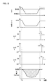
- FIG. 7 is a diagram showing the behavior of the system corresponding to the processing described with reference to FIGS. FIG.
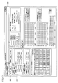
- FIG. 7 is a diagram illustrating an example of a screen (setting screen) for inputting setting contents used in the processing described with reference to FIGS. 4 to 6; It is a figure which shows an example of the display screen of the information regarding the energy by which consumption was suppressed. It is a figure for demonstrating evaluation of the consumption equipment by a controller. It is a flowchart of the subroutine of the operating time control in 2nd Embodiment. It is a flowchart of a subroutine of idling control in the second embodiment. It is a figure which shows the behavior of the system of FIG. 1 by control of 2nd Embodiment. It is a figure which shows an example of the screen which inputs the setting content in 2nd Embodiment.
- compressed air is adopted as an example of the fluid supplied to the system.
- fluids that can be supplied to the system include liquids such as cooling water and steam.
- FIG. 1 is a diagram illustrating an outline of a configuration of a system to be controlled by a system control apparatus. The outline of the configuration of the system will be described with reference to FIG.
- the consumption facility 2000 includes facilities 801 to 803 that receive a supply of compressed air and perform processing such as product manufacture and polishing.
- Supply facility 1000 includes compressors 601 to 604 that generate compressed air to be supplied to facilities 801 to 803.
- the compressed air generated in the compressors 601 to 604 is stored in the tank 500 via the pipe 900.
- the compressed air stored in the tank 500 is sent to the consumption facility 2000 via the trunk line 910 (supply line).
- the main line 910 is provided with a pressure sensor 701 for measuring the pressure in the main line 910.
- the control panel 400 drives the compressors 601 to 604 in order to maintain the pressure in the trunk line 910 at the control target of the trunk line 910 based on the measurement result of the pressure sensor 701.
- the control panel 400 uses the measurement result of the pressure sensor 701 to drive the compressors 601 to 604 by PID (Proportional Integral Differential) control.
- PID Proportional Integral Differential
- the control panel 400 may determine the number of compressors to be driven among the compressors 601 to 604 based on the measurement result of the pressure sensor 701. More specifically, the control panel 400 increases the number of compressors to be driven among the compressors 601 to 604 when the pressure in the main line 910 decreases, and increases the number of compressors to be driven when the pressure in the main line 910 increases. Reduce.
- the consumption facility 2000 is provided with branch pipes 911 to 913 for sending compressed air from the main line 910 to the respective facilities 801 to 803.
- the trunk line 910 is provided, for example, in a facility duct.
- the branch pipes 911 to 913 are configured as pipes drawn from the duct to equipment in the facility.
- the diameters of the branch pipes 911 to 913 (about 10 mm) are configured to be smaller than the diameter of the main line 910 (about 50 mm).
- the main line 910 is further provided with a flow rate sensor 722 for measuring the flow rate (instantaneous flow rate) of compressed air in the main line 910 and a valve 721 for adjusting the flow rate of compressed air from the tank 500 to the main line 910. ing.
- the controller 100 is provided in the consumption facility 2000.
- the controller 100 adjusts the degree of opening / closing of the trunk line 910 by the valve 721 based on the measurement results of the pressure sensor 701 and the flow rate sensor 722.
- the degree of opening and closing of the valve 721 By adjusting the degree of opening and closing of the valve 721, the flow rate of the compressed air from the tank 500 to the main line 910 is adjusted.
- the controller 100 can switch on / off the power to each of the facilities 801 to 803 by adjusting a switch of a switchboard that supplies power to each of the facilities 801 to 803.
- the controller 100 accepts input of various information including numerical values for system control, and displays information about the system.
- the controller 100 may perform a setting screen for inputting information and a screen for displaying information related to the system on the display device provided in the controller 100 or on other devices.
- the controller 100 can communicate with a personal computer (hereinafter abbreviated as “PC”) 300 and performs the above display on the display of the PC 300.
- PC personal computer
- FIG. 2 is a diagram schematically illustrating a hardware configuration of the controller 100.
- the controller 100 includes a CPU (Central Processing Unit) 10 that is an arithmetic device for controlling the entire controller 100 and a ROM (Read Only Memory) for storing programs executed by the CPU 10. 11, a RAM (Random Access Memory) 12 that functions as a work area when the CPU 10 executes a program, and a modem that performs communication such as reception of measurement results from the pressure sensor 701 and the flow sensor 722.
- Communication device 18, display interface 14 that is an interface for transmitting image data from controller 100 to PC 300, operation unit 15 for receiving operation input to controller 100, programs executed by CPU 10, and the like.
- a recording medium 16 for storage; From there to access the removable storage medium M to the controller 100 and a media controller 17 to read or write files.
- the operation unit 15 is realized by an input device such as a keyboard and a mouse.
- the communication device 18 is also used for transmitting information for switching the power on / off of the facilities 801 to 803 and for transmitting information for adjusting the degree of opening / closing of the valve 721.
- the valve 721 is realized by, for example, an electromagnetic valve having a communication function. The valve 721 adjusts the degree of opening and closing of the compressed air flow path in the trunk line 710 based on a control signal from the controller 100.
- the CPU 10 executes an appropriate program
- At least a part of the functions of the controller 100 described in the present specification is realized.
- At least a part of the program executed by the CPU 10 may be stored in the storage medium M.
- the storage medium M CD-ROM (Compact Disc-Read Only Memory), DVD-ROM (Digital Versatile Disk-Read Only Memory), USB (Universal Serial Bus) memory, memory card, FD (Flexible Disk), hard disk, Magnetic tape, cassette tape, MO (Magnetic Optical Disc), MD (Mini Disc), IC (Integrated Circuit) card (excluding memory card), optical card, mask ROM, EPROM, EEPROM (Electronically Erasable Programmable Read-Only Memory)
- a medium for storing the program in a nonvolatile manner For example, a medium for storing the program in a nonvolatile manner.
- the program executed by the CPU 10 may be downloaded from an external server device S via a network and installed in the recording medium 16.
- FIG. 3 is a diagram schematically illustrating a functional configuration of the controller 100.
- the controller 100 includes a data storage unit 101, a control information generation unit 102, a control information transmission unit 103, an energy saving information generation unit 104, and a display control unit 105.
- the data storage unit 101 is realized by the RAM 12 and / or the recording medium 16, for example.
- the control information generation unit 102, the energy saving information generation unit 104, and the display control unit 105 are realized, for example, by the CPU 10 executing an appropriate program. However, hardware resources independent of the CPU 10, such as a dedicated circuit, are realized. It may be realized by.
- the control information transmission unit 103 is realized by the communication device 18 that is instructed by the CPU 10 to transmit and receive data.
- the data storage unit 101 receives and stores the measurement results of the pressure sensor 701 and the flow sensor 722.
- the control information generation unit 102 controls the degree of opening and closing of the flow path by the valve 721 based on the history of measurement results accumulated in the data accumulation unit 101, various setting values stored in the controller 100, and the like. Information for on / off control of power supply to the facilities 801 to 803 is generated.
- the control information transmission unit 103 is connected to the valve 721 (or a device that controls the operation of the valve 721) and the facilities 801 to 803 (or the facilities 801 to 803).
- a device that controls the supply of power such as a switchboard, transmits a control signal.
- the energy saving information generation unit 104 generates information such as an energy amount whose consumption is suppressed in the system.
- the display control unit 105 generates various information display screens such as measurement results stored in the data storage unit 101 and information generated by the energy saving information generation unit 104, and transmits the screens to the PC 300.
- various screens related to processing in the controller 100 are displayed based on information received from the display control unit 105.
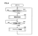
- FIG. 4 is a flowchart of a process for the CPU 10 of the controller 100 to control the supply of compressed air from the supply facility 1000 to the consumption facility 2000.
- 5 and 6 are flowcharts of the subroutine of the process of FIG.
- the flow of processing executed by the controller 100 will be described with reference to FIGS.
- step S10 the controller 100 determines whether or not the operation preparation time has arrived. If controller 100 determines that the operation preparation time has arrived, the controller 100 proceeds to step S20.
- the operation preparation time is a time at which preparation is started to bring the system into an operable state at the start of the operation state of the system in FIG.
- operating state and “non-operating state” are defined for the facilities 801 to 803.
- the operating state refers to a period during which at least one of the facilities 801 to 803 is operating.
- the operation means that each of the facilities 801 to 803 receives an electric power supply and executes an operation such as product processing.
- the non-operating state refers to a period other than the operating state.
- the start time of the operating state and the start time of the non-operating state are registered in advance in the controller 100 via the operation unit 15 or from another device via the communication device 18. Each registered time is stored in the recording medium 16, for example.
- the start time / end time of the operating state corresponds to the end time / start time of the non-operating state, respectively.
- information for specifying the length of time (preparation time) from the operation preparation time to the start time of the operation state is registered.
- step S20 the controller 100 executes the operation control and advances the process to step S30.
- the contents of the operation control will be described later with reference to FIG.
- step S30 the controller 100 determines whether or not the start time of the non-operating state has arrived. If controller 100 determines that the start time of the non-operating state has arrived, the controller 100 proceeds to step S40.
- step S40 the controller 100 executes idling control and returns the process to step S10.
- the content of idling control will be described later with reference to FIG.
- FIG. 5 is a flowchart of the operating time control subroutine of step S20 of FIG. Hereinafter, with reference to FIG. 5, processing contents of the on-time control will be described.
- controller 100 increases the opening of the flow path by valve 721 (hereinafter simply referred to as “opening of valve 721”), and proceeds to step S104.
- opening of valve 721 hereinafter simply referred to as “opening of valve 721”.
- step S104 the controller 100 determines whether or not the internal pressure of the trunk line 910 has reached a preset “target value 1” based on the measurement result of the pressure sensor 701. Then, the controller 100 waits until it is determined that the “target value 1” has been reached, and when it is determined that the target value has been reached, the process proceeds to step S106.
- step S106 the controller 100 maintains the opening degree of the valve 721 for a preset time “t1”, and further increases the opening degree of the valve 721 and advances the process to step S108.
- step S108 the controller 100 determines whether or not the internal pressure of the main line 910 has reached a preset “target value 2” based on the measurement result of the pressure sensor 701. Then, the controller 100 waits until it is determined that the “target value 2” has been reached, and if it is determined that it has reached, the process proceeds to step S110.
- step S110 the controller 100 maintains the opening degree of the valve 721 for a preset time “t2”, and further increases the opening degree of the valve 721, and proceeds to step S112.
- step S112 the controller 100 determines whether the internal pressure of the trunk line 910 has reached a preset “set value” based on the measurement result of the pressure sensor 701. Then, the controller 100 waits until it is determined that the “set value” has been reached, and if it is determined that it has reached, the process proceeds to step S114.
- step S114 the controller 100 turns on the power of the equipment 801 on condition that a preset time “T1” has elapsed since it was determined in step S112 that the internal pressure reached the “set value”. The channel “out1” of the controller 100 is turned on), and the process proceeds to step S116.
- step S116 the controller 100 turns on the power of the facility 802 on the condition that a preset time “T2” has elapsed since it was determined in step S112 that the internal pressure reached the “set value”.
- the channel “out2” of the controller 100 is turned on), and the process proceeds to step S118.
- step S118 the controller 100 turns on the power of the facility 803 on the condition that a preset time “T3” has elapsed since it was determined in step S112 that the internal pressure has reached the “set value”.
- the channel “out3” of the controller 100 is turned on), and the process returns to FIG.
- FIG. 6 is a flowchart of the idling control subroutine of step S40 in FIG.
- the processing content of the idling control will be described with reference to FIG.
- step S202 the controller 100 turns off the power of the facilities 801 to 803 (channels “out1,” “out2,” “out3” of the controller 100 are turned off), and proceeds to step S204.
- step S204 the controller 100 reduces the opening of the valve 721 and advances the process to step S206.
- the mode of reducing the opening degree of the valve 721 in Step S204 (the degree of reducing the opening degree per unit time, etc.), since a known technique can be adopted, the details thereof will not be repeated here.
- step S206 the controller 100 determines whether or not the opening of the valve 721 has been reduced to the extent that the flow path is closed to the maximum. The controller 100 continues to reduce the opening of the valve 721 until it is determined that the controller 100 has been reduced to that extent. If the controller 100 determines that the level has been reduced to that extent, it returns the process to FIG. 4.
- the compressed air supply line ( The degree of opening and closing of the main line 910) by the valve 721 is reduced. Further, according to the process described mainly with reference to FIG. 5, at the start of operation of the consumption facility 2000, the degree of opening and closing of the compressed air supply line (main line 910) to the consumption facility 2000 by the valve 721 is increased.
- the equipment 801 to 803 are turned on on the condition that the internal pressure of the supply line rises (recovers) to the “set value”.
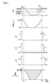
- FIG. 7 is a diagram showing the behavior of the system corresponding to the processing described with reference to FIGS. 7A shows the internal pressure of the trunk line 910.
- FIG. (B) shows the degree of opening and closing of the valve 721.
- (C), (D), and (E) indicate the on / off states of the power sources of the equipment 801 (out1), the equipment 802 (out2), and the equipment 803 (out3), respectively.
- (F) indicates the flow rate of the compressed air in the valve 721.
- Each of (A) to (F) of FIG. 7 shows the time change of each value.
- the time TA corresponds to the time when the idling control in FIG. 6 is started.
- Time TB corresponds to the start time of the operating state.
- the operation time control in FIG. 5 is started before the above preparation time from the start time of the operation state.
- the supply amount of the compressed air to the consumption facility 2000 can be suppressed while the consumption facility 2000 is not operating. Therefore, the consumption amount of compressed air in the supply facility 1000 can be suppressed, and thereby the consumption amount of power by the compressors 601 to 604 can be suppressed.
- the opening control of the valve 721 is started by starting the operation control in FIG. B).
- the flow rate of the compressed air in the main line 910 starts to increase (F)
- the internal pressure of the main line 910 starts to increase (A).
- the opening degree of the valve 721 is gradually increased. More specifically, as described as the processing of steps S104 to S110 in FIG. 5, when the internal pressure of the trunk line 910 reaches “target value 1”, the state is maintained for the time “t1”. When the internal pressure of the valve 721 reaches the “target value 2”, the opening degree of the valve 721 is controlled so that the state is maintained for the time “t2”. Thereby, it can avoid that the internal pressure of the trunk line 910 rises rapidly.
- the internal pressure of the main line 910 recovers to the “set value” or more by at least the time TB by the operation control of FIG.
- the equipment 801 to 803 in the consumption equipment 2000 is turned on in a predetermined sequence. Specifically, the power source of the facility 801 is turned on after T1 from the recovery of the internal pressure of the main line 910. Next, the power source of the facility 802 is turned on after T2 from the recovery of the internal pressure of the main line 910. Next, the power source of the facility 803 is turned on after T3 from the recovery of the internal pressure of the main line 910.
- FIG. 8 is a diagram showing an example of a screen (setting screen) for inputting setting contents used in the processing described with reference to FIGS. With reference to FIG. 8, input of various setting contents will be described.
- FIG. 8 shows a screen 310.
- the controller 100 displays the screen 310 on the display of the PC 300 when an operation for requesting the operation unit 15 to call the setting screen is performed or when the request is input via the PC 300.
- the screen 310 includes a display field 314 for inputting setting contents of the “set value” and the times “T1”, “T2”, and “T3”.
- the “target value” input field corresponds to the “set value” input field.
- the input fields for “Delay 1”, “Delay 2”, and “Delay 3” correspond to the input fields for “T1”, “T2”, and “T3”, respectively.
- the screen 310 includes a display field 315 for inputting the setting contents of the “target value 1”, “target value 2”, and times “t1” and “t2”.
- the input fields for pressure and time for “target value 1” in the display field 315 correspond to the input fields for “target value 1” and “t1”. Further, the pressure and time input fields for “target value 2” in the display field 315 correspond to the input fields for “target value 2” and “t2”.
- the setting content input to the screen 310 is stored in the recording medium 16, for example.
- Each setting content may be stored in a storage device outside the controller 100, and the CPU 10 may acquire the setting content from the storage device and execute the processing described with reference to FIGS.
- the controller 100 can display information on energy whose consumption is suppressed by executing the processing described with reference to FIGS. More specifically, the controller 100 integrates the difference between the flow rate of the compressed air during the period from time TA to time TB in FIG. 7F (FIG. 7) (see FIG. 7). (Corresponding to the hatched portion of (F)) is displayed as the information.
- controller 100 displays the product of the integrated value and the cost per unit volume of the compressed air as the cost suppressed by suppressing the energy consumption.
- the cost per unit volume of the compressed air is registered in advance in the recording medium 16 or the like, for example.
- FIG. 9 is a diagram showing an example of a display screen for information on energy whose consumption is suppressed.
- the integrated value is displayed in a column 751
- the “suppressed cost” is displayed in a column 752.
- the screen 750 displays information specifying the time TB from the time TA as “October 31st 13:00 to 16:00”.
- the controller 100 In the non-operating state, the controller 100 is more effective in reducing the supply amount of compressed air to the consuming equipment 2000 than in the operating state, and as shown in the screen 750 in FIG. Displayed.
- the controller 100 can evaluate the degree of deterioration of the consuming equipment 2000 based on the contents of the processing described with reference to FIGS.
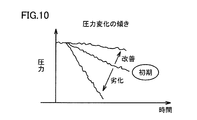
- the degree of deterioration of the consumption facility 2000 can be evaluated based on the degree of decrease in the pressure of the main line 910 at the start of idling control. More specifically, as shown in FIG. 10, if the rate of pressure decrease at the start of idling control is faster than when idling control is performed in the initial state of the consuming equipment 2000, consumption will occur. The facility 2000 is considered degraded. On the other hand, when the rate of the decrease is slower than the initial state, it is considered that the deterioration of the consumption equipment 2000 has been improved.
- the controller 100 causes the PC 300 to display the result of such evaluation, for example, every predetermined period or in response to a request input to the operation unit 15 or a request from an external device.
- the opening degree of the valve 721 is adjusted so that the internal pressure of the main line 910 is reduced to a preset pressure value ("target value 3" described later).
- the opening degree of the valve 721 is raised without going through a step.
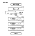
- FIG. 11 is a flowchart of an operating time control subroutine according to the second embodiment.
- FIG. 12 is a flowchart of an idling control subroutine according to the second embodiment.
- the process of FIG. 11 is executed instead of the process of FIG. 5
- the process of FIG. 12 is executed instead of the process of FIG.
- step SA102 controller 100 increases the opening of valve 721 and advances the process to step SA112.
- step SA112. About the aspect which raises an opening degree (degree etc. which reduce the opening degree per unit time, etc.), since a well-known technique is employable, the detail is not repeated here.
- step SA112 the controller 100 determines whether or not the internal pressure of the trunk line 910 has reached a preset “set value” based on the measurement result of the pressure sensor 701. Then, the controller 100 waits until it is determined that the “set value” has been reached, and if it is determined that it has reached, the process proceeds to step SA114.
- step SA114 the controller 100 turns on the power of the equipment 801 on condition that a preset time “T1” has elapsed since it was determined in step SA112 that the internal pressure reached the “set value”. Then, the process proceeds to step SA116.
- step SA116 the controller 100 turns on the power of the facility 802 on the condition that a preset time “T2” has elapsed since it was determined in step SA112 that the internal pressure reached the “set value”. Then, the process proceeds to step SA118.
- step SA118 the controller 100 turns on the power of the facility 803 on the condition that a preset time “T3” has elapsed since it was determined in step SA112 that the internal pressure reached the “set value”. Then, the process returns to FIG.
- step SA202 controller 100 turns off the equipment 801 to 803 and advances the process to step SA204.
- step SA204 the controller 100 reduces the opening of the valve 721 and advances the process to step SA206.
- the mode of reducing the opening degree of the valve 721 in Step SA204 the degree of reducing the opening degree per unit time, etc.
- the details thereof will not be repeated here.
- step SA206 the controller 100 determines whether or not the internal pressure of the trunk line 910 has decreased to a preset “target value 3”. The controller 100 continues to reduce the opening of the valve 721 until it determines that the internal pressure of the main line 910 has decreased to “target value 3”. If controller 100 determines that the value has decreased to “target value 3”, it proceeds to step SA208.
- step SA208 the controller 100 continues the adjustment of the opening of the valve 721 so that the internal pressure of the main line 910 is maintained at the “target value 3” or more, and returns the process to FIG.
- the internal pressure of the trunk line 910 is maintained at the “target value 3” or more until the next operation control is started.
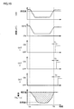
- FIG. 13 is a diagram illustrating the behavior of the system of FIG. 1 under the control of the second embodiment.
- (A) to (F) in FIG. 13 represent the same contents as (A) to (F) in FIG. Specifically, (A) shows the internal pressure of the trunk line 910.
- (B) shows the degree of opening and closing of the valve 721.
- (C), (D), and (E) indicate the on / off states of the power sources of the equipment 801 (out1), the equipment 802 (out2), and the equipment 803 (out3), respectively.
- (F) shows the flow rate of the compressed air in the valve 721.
- the internal pressure of the trunk line 910 is maintained at the target value 3 or more during the period from time TA to time TB.
- FIG. 14 is a diagram illustrating an example of a screen for inputting setting contents according to the second embodiment.
- the “target value” input field of the display field 323 corresponds to the “target value 3” input field.
- the “target value” input field corresponds to the “set value” input field.
- the input fields of “Delay 1”, “Delay 2”, and “Delay 3” correspond to the input fields of “T1”, “T2”, and “T3”.
- FIG. 15 is a flowchart of an operating time control subroutine according to the third embodiment.
- the process of FIG. 15 is executed instead of the process of FIG. Since the on-time control of the present embodiment can be the same as that of the second embodiment, detailed description will not be repeated.
- step SA302 controller 100 turns off the power of facilities 801 to 803, and proceeds to step SA304.
- step SA304 the controller 100 reduces the opening of the valve 721 and advances the process to step SA306.
- the mode of reducing the opening degree of the valve 721 in Step SA304 the degree to which the opening degree per unit time is reduced, etc.
- known techniques can be adopted, the details thereof will not be repeated here.
- step SA306 the controller 100 determines whether or not the flow rate of the compressed air in the main line 910 has decreased to a preset “target value 4”. The controller 100 continues to reduce the opening of the valve 721 until it is determined that the flow rate has decreased to “target value 4”. If controller 100 determines that the flow rate has decreased to “target value 4”, it proceeds to step SA308.
- step SA308 the controller 100 continues the adjustment of the opening degree of the valve 721 so that the flow rate of the compressed air in the main line 910 is maintained at the “target value 4”, and returns the process to FIG.
- the flow rate of the compressed air in the main line 910 is maintained at the “target value 4” or more until the next start of operation control.
- FIG. 16 is a diagram illustrating the behavior of the system of FIG. 1 under the control of the third embodiment.
- (A) to (F) in FIG. 16 represent the same contents as (A) to (F) in FIG. Specifically, (A) shows the internal pressure of the trunk line 910.
- (B) shows the degree of opening and closing of the valve 721.
- (C), (D), and (E) indicate the on / off states of the power sources of the equipment 801 (out1), the equipment 802 (out2), and the equipment 803 (out3), respectively.
- (F) shows the flow rate of the compressed air in the valve 721.
- the flow rate of the compressed air in the main line 910 is maintained at the target value 4 or more during the period from time TA to time TB.
- FIG. 17 is a diagram illustrating an example of a screen for inputting setting contents according to the third embodiment.
- the “target value” input field of the display field 333 corresponds to the “target value 4” input field.
- the “target value” input field corresponds to the “setting value” input field in the display field 334.
- the input fields for “Delay 1”, “Delay 2”, and “Delay 3” correspond to the input fields for “T1”, “T2”, and “T3”, respectively.
- control device described in the present embodiment can be applied to control of other fluids (for example, nitrogen gas, cooling water, hot water, etc.) in addition to control of the flow rate of compressed air and the like.
- other fluids for example, nitrogen gas, cooling water, hot water, etc.
- controller 101 data storage unit, 102 control information generation unit, 103 control information transmission unit, 104 energy saving information generation unit, 105 display control unit, 300 PC, 400 control panel, 701 pressure sensor, 722 flow sensor, 801 to 803 facilities 910 Main line.
Landscapes
- Physics & Mathematics (AREA)
- General Physics & Mathematics (AREA)
- Engineering & Computer Science (AREA)
- Automation & Control Theory (AREA)
- Fluid Mechanics (AREA)
- Control Of Fluid Pressure (AREA)
- Flow Control (AREA)
- Control Of Positive-Displacement Pumps (AREA)
Abstract
流体の供給源と設備とを接続する供給ラインの開閉の度合いを制御するライン制御装置(100)において、記憶部(12,16)は、設備の稼働状態および非稼働状態を特定する情報を記憶する。取得部(18)は、供給ラインの内圧を取得する。制御部(10)は、非稼働状態での供給ラインの開度を、供給ラインの内圧を設備の許容範囲内の値である所定の圧力以上で維持しながら、稼働状態における開度よりも低下させる。
Description
本開示は、エネルギを消費して製造される流体の供給源と設備とを接続する供給ラインの開閉の度合いの制御に関する。
従来、工場等のシステムにおける消費電力の低減に関し、種々の技術が開示されている。たとえば、特許文献1(特開2001-034323号公報)には、自己の消費電力を測定して外部へ送信する工作機械が開示されている。特許文献2(特開2007-148726号公報)には、工場において、工程ごとに、用力負荷の推移やエネルギ消費量の推移を含むエネルギ消費を分析する装置が開示されている。
また、上記のようなシステムには、圧縮空気送出用コンプレッサから、配管を介して、各装置に圧縮空気を供給するシステムなど、エネルギを消費して製造される流体を利用するものがある。このようなシステムについて、コンプレッサの駆動によるエネルギ消費を抑えるための種々の技術が開示されている。たとえば、特許文献3(特開2004-176683号公報)、特許文献4(特開2007-291870号公報)、特許文献5(特開2011-226586号公報)、および、特許文献6(特開2012-031789号公報)には、コンプレッサの電力消費を抑えるための技術が開示されている。
上記のような従来のシステムでは、工作機械やコンプレッサ等、装置自体の消費電力の低減については検討されているものの、圧縮空気等の流体の消費量自体の削減については具体的な検討がなされていない。
しかしながら、上記したようなシステムでは、流体の生成においても、コンプレッサの駆動等の動力を必要とする。このことから、流体の消費量の削減について検討することも、流体の生成に要する動力の削減に寄与し、ひいては、システムにおけるエネルギ消費量の削減に寄与し得る。
本開示は、かかる実情に鑑み考え出されたものであり、その目的は、エネルギを消費して製造される流体を利用するシステムにおけるエネルギの消費量を削減することである。
ある局面に従うと、流体の供給源と設備とを接続する供給ラインの開閉の度合いを制御するライン制御装置が提供される。ライン制御装置は、設備の稼働状態および非稼働状態を特定する情報を記憶するための記憶部と、供給ラインの内圧または流体の流量を取得するための取得部と、非稼働状態での供給ラインの開度を、供給ラインの内圧または流体の流量を設備の許容範囲内の値である所定の圧力以上または所定の流量以上で維持しながら、稼働状態における開度よりも低下させる制御部とを備える。
好ましくは、ライン制御装置は、設備への電力の供給を制御するための電力供給部をさらに備える。制御部は、非稼働状態から稼働状態への移行時に、供給ラインの開度を上昇させ、電力供給部は、非稼働状態から稼働状態への移行時に、供給ラインの内圧が設備の稼働に適した設定値に到達したことを条件として、設備への電力の投入を開始する。
好ましくは、ライン制御装置は、設備への電力の供給を制御するための電力供給部をさらに備える。電力供給部は、非稼働状態から稼働状態への移行時に、供給ラインの内圧が設備の稼働に適した設定値に到達したことを条件として、設備への電力の投入を開始する。
好ましくは、供給ラインには複数の設備が接続され、電力供給部は、非稼働状態から稼働状態への移行時に、供給ラインの内圧が設定値に到達したことを条件として、複数の設備中で予め定められた順序で、複数の設備への電力の投入を開始する。
好ましくは、制御部は、非稼働状態から稼働状態への移行時に、供給ラインの開度を段階的に上昇させる。
好ましくは、制御部は、供給ラインの開度を或る段階に上昇させたとき、供給ラインの内圧が当該或る段階に対応する圧力まで上昇したことを条件として、次の段階へと供給ラインの開度を上昇させる。
好ましくは、制御部は、非稼働状態において、供給ラインの開度を稼働状態での開度より低下させたことによって消費を抑えられたエネルギに関する情報を表示する。
好ましくは、情報は、非稼働状態において、供給ラインの開度を稼働状態での開度より低下させたことによって供給ラインへの流出を抑えられた流体の量に基づく情報である。
さらに他の局面に従うと、流体の供給源と設備とを接続する供給ラインの開閉の度合いを制御するライン制御装置の制御方法が提供される。ライン制御装置のコンピュータは、設備の稼働状態および非稼働状態を特定する情報を記憶するための記憶装置を含む。当該制御方法は、ライン制御装置のコンピュータが、供給ラインの内圧または流体の流量を取得するステップと、非稼働状態での供給ラインの開度を、供給ラインの内圧または流体の流量を設備の許容範囲内の値である所定の圧力以上または所定の流量以上で維持しながら、稼働状態における開度よりも低下させるステップとを含む。
さらに他の局面に従うと、流体の供給源と設備とを接続する供給ラインの開閉の度合いを制御するためのコンピュータが実行可能なプログラムが提供される。コンピュータは、設備の稼働状態および非稼働状態を特定する情報を記憶するための記憶装置を含む。当該プログラムは、コンピュータに、供給ラインの内圧または流体の流量を取得するステップと、非稼働状態での供給ラインの開度を、供給ラインの内圧または流体の流量を設備の許容範囲内の値である所定の圧力以上または所定の流量以上で維持しながら、稼働状態における開度よりも低下させるステップとを実行させる。
さらに他の局面に従うと、流体の供給源と設備とを接続する供給ラインの開閉の度合いを制御するに実行されるプログラムを、コンピュータが読取可能に、非一時的に記憶する記憶媒体が提供される。コンピュータは、設備の稼働状態および非稼働状態を特定する情報を記憶するための記憶装置を含む。当該プログラムは、コンピュータに、供給ラインの内圧または流体の流量を取得するステップと、非稼働状態での供給ラインの開度を、供給ラインの内圧または流体の流量を設備の許容範囲内の値である所定の圧力以上または所定の流量以上で維持しながら、稼働状態における開度よりも低下させるステップとを実行させる。
ある局面に従うと、設備の非稼働状態での供給ラインの開度が、当該供給ライン内を設備の許容範囲内の値である所定の圧力以上または所定の流量以上で維持しながら、稼働状態における開度よりも低下する。
これにより、非稼働状態では、供給ラインの内圧の低下による影響を抑えながら、エネルギ流体の供給ラインへの供給量を低減できる。本開示の流体は、電力等のエネルギを用いて製造される流体である。本開示は、流体の使用量の低減を図ることができ、これにより、電力等のエネルギの使用量の削減に寄与する。
他の局面に従うと、設備の非稼働状態での供給ラインの開度がその稼働状態における開度よりも低下する。さらに、設備の非稼働状態から稼働状態への移行時に、供給ラインの内圧が設備の稼働に適した特定の圧力以上に到達したことを条件として、当該設備への電力の投入が開始される。
これにより、非稼働状態においてエネルギ流体の供給ラインへの供給量を低減し、かつ、非稼働状態から稼働状態に移行する際には、非稼働状態において供給ラインの内圧が低減されていたことによる設備への影響が抑えられる。
以下、流体の一例として圧縮空気が供給されるシステムの制御装置の実施の形態について、図面を参照しつつ説明する。なお、同一の構成要素には各図において同一の符号を付し、詳細な説明は繰返さない。
本明細書では、システムに供給される流体の一例として、圧縮空気が採用される。システムに供給され得る流体の他の例としては、冷却水等の液体や蒸気が挙げられる。
<第1の実施の形態>
[システムの概要]
図1は、システム制御装置の制御対象となるシステムの構成の概要を示す図である。図1を参照して、当該システムの構成の概要を説明する。
[システムの概要]
図1は、システム制御装置の制御対象となるシステムの構成の概要を示す図である。図1を参照して、当該システムの構成の概要を説明する。
図1のシステムは、供給設備1000と、消費設備2000とを含む。消費設備2000は、圧縮空気の供給を受けて、製品の製造や研磨等の処理を行う設備801~803を含む。供給設備1000は、設備801~803に供給される圧縮空気を生成するコンプレッサ601~604を含む。
供給設備1000は、コンプレッサ601~604において生成された圧縮空気は、配管900を介して、タンク500で貯蔵される。タンク500に貯蔵された圧縮空気は、幹線910(供給ライン)を介して、消費設備2000へと送られる。幹線910には、当該幹線910内の圧力を計測するための圧力センサ701が設けられている。供給設備1000において、制御盤400は、圧力センサ701の計測結果に基づいて、幹線910内の圧力を当該幹線910の制御目標で維持するために、コンプレッサ601~604を駆動する。制御盤400は、たとえば、圧力センサ701の計測結果を利用し、PID(Proportional Integral Differential)制御により、コンプレッサ601~604を駆動する。
制御盤400は、圧力センサ701の計測結果に基づいて、コンプレッサ601~604の中のコンプレッサの駆動台数を決定する場合もある。より具体的には、制御盤400は、幹線910内の圧力が低くなると、コンプレッサ601~604のうち駆動させるコンプレッサの台数を増加させ、幹線910内の圧力が高くなると、駆動させるコンプレッサの台数を低減させる。
消費設備2000には、幹線910から各設備801~803へと圧縮空気を送るための枝管911~913が設けられている。幹線910は、たとえば施設のダクト内に設けられている。枝管911~913は、当該ダクトから施設内の設備へと引き出された配管として構成される。一般的に、枝管911~913の径(10mm程度)は、幹線910の径(50mm程度)よりも小さく構成される。
幹線910には、さらに、当該幹線910内の圧縮空気の流量(瞬時流量)を計測する流量センサ722と、タンク500から幹線910への圧縮空気の流量を調整するためのバルブ721とが設けられている。
消費設備2000には、コントローラ100が設けられている。コントローラ100は、圧力センサ701や流量センサ722の計測結果に基づいて、バルブ721による幹線910の開閉の度合いを調整する。バルブ721の開閉の度合いが調整されることにより、タンク500から幹線910への圧縮空気の流量が調整される。
コントローラ100は、設備801~803のそれぞれへ電力を供給する配電盤のスイッチの調整等により、設備801~803のそれぞれへの電源のオン/オフを切り替えることができる。
コントローラ100は、システムの制御のための数値を含む種々の情報の入力を受け付け、また、システムに関する情報を表示する。コントローラ100は、情報の入力のための設定画面や、システムに関する情報を表示する画面を、当該コントローラ100に備えられた表示装置で行ってもよいし、他の機器において行ってもよい。本実施の形態では、コントローラ100は、パーソナルコンピュータ(以下、「PC」と略す)300と通信可能であり、PC300のディスプレイにおいて上記表示を行なう。
[コントローラ100のハードウェア構成]
図2は、コントローラ100のハードウェア構成を模式的に示す図である。
図2は、コントローラ100のハードウェア構成を模式的に示す図である。
図2を参照して、コントローラ100は、コントローラ100全体を制御するための演算装置であるCPU(Central Processing Unit)10と、CPU10で実行されるプログラムなどを記憶するためのROM(Read Only Memory)11と、CPU10でプログラムを実行する際の作業領域として機能するためのRAM(Random Access Memory)12と、圧力センサ701や流量センサ722からの計測結果の受信などの通信を行なうモデム等により実現される通信装置18と、コントローラ100からPC300への画像データの送信の際のインターフェースである表示用インターフェース14と、コントローラ100に対する操作入力を受付けるための操作部15と、CPU10によって実行されるプログラム等を格納するための記録媒体16と、コントローラ100に対して着脱可能な記憶媒体Mにアクセスしてそこからファイルを読み出したり書き込んだりするためのメディアコントローラ17とを含む。
操作部15は、たとえばキーボードやマウスなどの入力装置によって実現される。通信装置18は、設備801~803の電源のオン/オフ切替えのための情報の送信や、バルブ721の開閉度合いの調整のための情報の送信にも利用される。バルブ721は、たとえば、通信機能を有する電磁弁によって実現される。バルブ721は、コントローラ100からの制御信号に基づいて、幹線710における圧縮空気の流路の開閉の度合いを調整する。
本実施の形態では、たとえば、CPU10が適切なプログラムを実行することにより、本明細書に記載されたコントローラ100の機能の少なくとも一部が実現される。CPU10が実行するプログラムの少なくとも一部は、上記記憶媒体Mに記憶されていても良い。記憶媒体Mとしては、CD-ROM(Compact Disc - Read Only Memory)、DVD-ROM(Digital Versatile Disk - Read Only Memory)、USB(Universal Serial Bus)メモリ、メモリカード、FD(Flexible Disk)、ハードディスク、磁気テープ、カセットテープ、MO(Magnetic Optical Disc)、MD(Mini Disc)、IC(Integrated Circuit)カード(メモリカードを除く)、光カード、マスクROM、EPROM、EEPROM(Electronically Erasable Programmable Read-Only Memory)などの、不揮発的にプログラムを格納する媒体が挙げられる。
また、CPU10が実行するプログラムは、ネットワークを介して、外部のサーバ装置Sからダウンロードされ、記録媒体16にインストールされる場合も有り得る。
[コントローラ100の機能構成]
図3は、コントローラ100の機能構成を模式的に示す図である。
図3は、コントローラ100の機能構成を模式的に示す図である。
図3を参照して、コントローラ100は、データ蓄積部101と、制御情報生成部102と、制御情報送信部103と、省エネ情報生成部104と、表示制御部105とを含む。データ蓄積部101は、たとえば、RAM12および/または記録媒体16によって実現される。制御情報生成部102、省エネ情報生成部104、および、表示制御部105は、たとえばCPU10が適切なプログラムを実行することによって実現されるが、専用の回路等、CPU10に対して独立したハードウェア資源によって実現される場合もあり得る。制御情報送信部103は、CPU10によってデータの送受信を指示される通信装置18によって実現される。
データ蓄積部101は、圧力センサ701および流量センサ722の計測結果を、受信し、蓄積する。
制御情報生成部102は、データ蓄積部101に蓄積された計測結果の履歴や、コントローラ100に格納される各種の設定値等に基づいて、バルブ721による上記流路の開閉度合いの制御、および、設備801~803への電力の供給のオン/オフの制御のための情報を生成する。
制御情報送信部103は、制御情報生成部102が生成した情報に基づいて、バルブ721(または、バルブ721の動作を制御する装置)、および、設備801~803(または、設備801~803への電力の供給を制御する装置。配電盤等)へ、制御信号を送信する。
省エネ情報生成部104は、システムにおいて消費を抑えられたエネルギ量等の情報を生成する。
表示制御部105は、データ蓄積部101に蓄積された計測結果や、省エネ情報生成部104によって生成された情報等の、各種の情報の表示用画面を生成し、PC300へ送信する。PC300では、表示制御部105から受信した情報に基づいて、コントローラ100における処理に関する各種の画面が表示される。
[制御フロー]
図4は、コントローラ100のCPU10が、供給設備1000から消費設備2000への圧縮空気の供給を制御するための処理のフローチャートである。また、図5および図6は、図4の処理のサブルーチンのフローチャートである。以下、図4~図6を参照して、コントローラ100が実行する処理の流れを説明する。
図4は、コントローラ100のCPU10が、供給設備1000から消費設備2000への圧縮空気の供給を制御するための処理のフローチャートである。また、図5および図6は、図4の処理のサブルーチンのフローチャートである。以下、図4~図6を参照して、コントローラ100が実行する処理の流れを説明する。
図4を参照して、まずステップS10で、コントローラ100は、稼働準備時刻が到来しているか否かを判断する。そして、コントローラ100は、稼働準備時刻が到来したと判断するとステップS20へ処理を進める。稼働準備時刻とは、図1のシステムの稼働状態の開始時に当該システムを稼働可能な状態とするために準備を開始する時刻である。
本実施の形態において、設備801~803について、「稼働状態」と「非稼働状態」とが定義される。稼働状態とは、設備801~803の少なくとも一つが、稼働する期間をいう。稼働とは、設備801~803のそれぞれが、電力の供給を受けて、製品の加工等の動作を実行することをいう。非稼働状態とは、稼働状態以外の期間をいう。
稼働状態の開始時刻および非稼働状態の開始時刻は、予め操作部15を介して、または、通信装置18を介して他の装置から、コントローラ100に登録されているものとする。登録されている各時刻は、たとえば記録媒体16に格納される。本実施の形態では、稼働状態の開始時刻/終了時刻は、それぞれ、非稼働状態の終了時刻/開始時刻に相当する。また、コントローラ100には、稼働準備時刻から稼働状態の開始時刻までの時間の長さ(準備時間)を特定する情報が登録されている。
ステップS20では、コントローラ100は、稼働時制御を実行して、ステップS30へ処理を進める。稼働時制御の内容については、図5を参照して後述する。
ステップS30では、コントローラ100は、非稼働状態の開始時刻が到来したか否かを判断する。そして、コントローラ100は、非稼働状態の開始時刻が到来したと判断するとステップS40へ処理を進める。
ステップS40では、コントローラ100は、アイドリング制御を実行して、ステップS10へ処理を戻す。アイドリング制御の内容については、図6を参照して後述する。
図5は、図4のステップS20の稼働時制御のサブルーチンのフローチャートである。以下、図5を参照して、稼働時制御の処理内容を説明する。
図5を参照して、ステップS102では、コントローラ100は、バルブ721による流路の開度(以下、単に「バルブ721の開度」という)を上昇させて、ステップS104へ処理を進める。開度を上昇させる態様(単位時間あたりの開度を低減する度合い、等)については、公知技術を採用することができるため、ここではその詳細は繰り返さない。
ステップS104では、コントローラ100は、圧力センサ701の計測結果に基づいて、幹線910の内圧が予め設定された「目標値1」に到達したか否かを判断する。そして、コントローラ100は、「目標値1」に到達したと判断するまで待機し、到達したと判断するとステップS106へ処理を進める。
ステップS106では、コントローラ100は、予め設定された時間「t1」だけバルブ721の開度を維持した後、さらに、バルブ721の開度を上昇させて、ステップS108へ処理を進める。
ステップS108では、コントローラ100は、圧力センサ701の計測結果に基づいて、幹線910の内圧が予め設定された「目標値2」に到達したか否かを判断する。そして、コントローラ100は、「目標値2」に到達したと判断するまで待機し、到達したと判断するとステップS110へ処理を進める。
ステップS110では、コントローラ100は、予め設定された時間「t2」だけバルブ721の開度を維持した後、さらに、バルブ721の開度を上昇させて、ステップS112へ処理を進める。
ステップS112では、コントローラ100は、圧力センサ701の計測結果に基づいて、幹線910の内圧が予め設定された「設定値」に到達したか否かを判断する。そして、コントローラ100は、「設定値」に到達したと判断するまで待機し、到達したと判断するとステップS114へ処理を進める。
図5に示された処理では、幹線910の内圧について設定された各値は、以下の式(1)の関係にある。
目標値1<目標値2<設定値 …(1)
ステップS114では、コントローラ100は、ステップS112において上記内圧が上記「設定値」に到達したと判断されてから予め設定された時間「T1」が経過したことを条件として、設備801の電源をオン(コントローラ100のチャンネル「out1」をオン)して、ステップS116へ処理を進める。
ステップS114では、コントローラ100は、ステップS112において上記内圧が上記「設定値」に到達したと判断されてから予め設定された時間「T1」が経過したことを条件として、設備801の電源をオン(コントローラ100のチャンネル「out1」をオン)して、ステップS116へ処理を進める。
ステップS116では、コントローラ100は、ステップS112において上記内圧が上記「設定値」に到達したと判断されてから予め設定された時間「T2」が経過したことを条件として、設備802の電源をオン(コントローラ100のチャンネル「out2」をオン)して、ステップS118へ処理を進める。
ステップS118では、コントローラ100は、ステップS112において上記内圧が上記「設定値」に到達したと判断されてから予め設定された時間「T3」が経過したことを条件として、設備803の電源をオン(コントローラ100のチャンネル「out3」をオン)して、図4へ処理をリターンさせる。
図6は、図4のステップS40のアイドリング制御のサブルーチンのフローチャートである。以下、図6を参照して、アイドリング制御の処理内容を説明する。
図6を参照して、ステップS202で、コントローラ100は、設備801~803の電源をオフ(コントローラ100のチャンネル「out1」「out2」「out3」をオフ)して、ステップS204へ処理を進める。
ステップS204で、コントローラ100は、バルブ721の開度を低減させて、ステップS206へ処理を進める。ステップS204においてバルブ721の開度の低減の態様(単位時間あたりの開度を低減する度合い、等)については、公知技術を採用することができるため、ここではその詳細は繰り返さない。
ステップS206では、コントローラ100は、バルブ721の開度が、上記流路を最大限閉じる程度まで低減されたか否かを判断する。コントローラ100は、当該程度まで低減されたと判断するまで、継続して、バルブ721の開度を低減する。そして、コントローラ100は、当該程度まで低減されたと判断すると、図4へ処理をリターンさせる。
以上、主に図6を参照して説明された処理によれば、消費設備2000の稼働の終了時には、設備801~803の電源がオフされた後、消費設備2000への圧縮空気の供給ライン(幹線910)の、バルブ721による開閉の度合いが低減される。また、主に図5を参照して説明された処理によれば、消費設備2000の稼働の開始時には、消費設備2000への圧縮空気の供給ライン(幹線910)の、バルブ721による開閉の度合いが上昇し、当該供給ラインの内圧が「設定値」まで上昇(回復)したことを条件として、設備801~803の電源がオンされる。
図7は、図4~図6を参照して説明した処理に対応した、システムの挙動を示す図である。図7において、(A)は、幹線910の内圧を示す。(B)は、バルブ721の開閉の度合いを示す。(C),(D),(E)は、それぞれ、設備801(out1),設備802(out2),設備803(out3)のそれぞれの電源のオン/オフの状態を示す。(F)は、バルブ721内の圧縮空気の流量を示す。図7の(A)~(F)は、いずれも各値の時間変化を示す。これらの図において、時刻TAは、図6のアイドリング制御が開始された時刻に相当する。時刻TBは、稼働状態の開始時刻に相当する。図5の稼働時制御は、稼働状態の開始時刻より上記準備時間以上前に開始される。
図7から理解されるように、時刻TAからバルブ721の開度の低減が開始されることにより(B)、幹線910内の圧縮空気の流量の低下が始まり(F)、幹線910の内圧の低下が始まる(A)。そして、バルブが閉じられる(開度0%)ことにより(B)、幹線910内の圧縮空気の流量が0(NL/min)に近づき(F)、幹線910の内圧は大気圧まで低下する(A)。
これにより、本実施の形態のシステムでは、消費設備2000の非稼働状態に、消費設備2000への圧縮空気の供給量を抑えることができる。したがって、供給設備1000における圧縮空気の消費量を抑えることができ、これにより、コンプレッサ601~604による電力の消費量を抑えることができる。
また、図7から理解されるように、上記のようにバルブ721の開度が低減された後、図5の稼働時制御が開始することにより、バルブ721の開度の上昇が開始される(B)。これにより、幹線910内の圧縮空気の流量が上昇を開始し(F)、幹線910の内圧の上昇が始まる(A)。
このとき、バルブ721の開度は、段階的に上昇している。より具体的には、図5のステップS104~ステップS110の処理として説明したように、幹線910の内圧が「目標値1」に到達するとその状態が時間「t1」だけ維持し、さらに、幹線910の内圧が「目標値2」に到達するとその状態が時間「t2」だけ維持するように、バルブ721の開度が制御される。これにより、幹線910の内圧が急激に上昇することを回避できる。
図1のシステムでは、図5の稼働時制御により、少なくとも時刻TBまでには、幹線910の内圧は「設定値」以上に回復する。
また、本実施の形態では、幹線910の内圧が「設定値」まで回復した後、消費設備2000内の設備801~803は、これらの中で予め定められたシーケンスで、電源をオンされる。具体的には、幹線910の内圧の回復からT1後、設備801の電源がオンされる。次に、幹線910の内圧の回復からT2後、設備802の電源がオンされる。次に、幹線910の内圧の回復からT3後、設備803の電源がオンされる。このようなシーケンスで各設備の電源がオンされることにより、消費設備2000内の環境をより安全に保持できる。ただし、消費設備2000の環境が、複数の設備の間で電源をオンする順序等に影響を受けることがない場合には、設備801~803の間での電源オンの順序は考慮される必要はない。
[設定画面]
図8は、図4~図6を参照して説明した処理において利用された設定内容を入力するための画面(設定画面)の一例を示す図である。図8を参照して、各種の設定内容の入力について説明する。
図8は、図4~図6を参照して説明した処理において利用された設定内容を入力するための画面(設定画面)の一例を示す図である。図8を参照して、各種の設定内容の入力について説明する。
図8には、画面310が示されている。コントローラ100は、操作部15に対して設定画面を呼出を要求する操作がなされると、または、PC300を介して当該要求が入力されると、PC300のディスプレイに画面310を表示させる。
画面310は、上記「設定値」、時間「T1」「T2」「T3」の設定内容を入力するための表示欄314を含む。表示欄314において、「目標値」の入力欄が上記「設定値」の入力欄に相当する。また、「ディレイ1」,「ディレイ2」,「ディレイ3」のそれぞれの入力欄が、上記「T1」「T2」「T3」の入力欄に相当する。
画面310は、上記「目標値1」「目標値2」および時間「t1」「t2」の設定内容を入力するための表示欄315を含む。表示欄315の「目標値1」についての圧力と時間の入力欄が、上記「目標値1」と「t1」の入力欄に相当する。また、表示欄315の「目標値2」についての圧力と時間の入力欄が、上記「目標値2」と「t2」の入力欄に相当する。
画面310に対して入力された設定内容は、たとえば、記録媒体16に格納される。なお、各設定内容は、コントローラ100外の記憶装置に格納され、CPU10は、当該設定内容を当該記憶装置から取得して図4~図6を参照して説明した処理を実行してもよい。
[効果の報知]
コントローラ100は、図4~図6を参照して説明した処理が実行されることにより消費を抑えられたエネルギに関する情報を表示することができる。より具体的には、コントローラ100は、図7の(F)の時刻TAから時刻TBまでの期間の圧縮空気の流量の、当該圧縮空気の流量についての規定値との差の積分値(図7の(F)のハッチング部分に相当)を、当該情報として表示する。
コントローラ100は、図4~図6を参照して説明した処理が実行されることにより消費を抑えられたエネルギに関する情報を表示することができる。より具体的には、コントローラ100は、図7の(F)の時刻TAから時刻TBまでの期間の圧縮空気の流量の、当該圧縮空気の流量についての規定値との差の積分値(図7の(F)のハッチング部分に相当)を、当該情報として表示する。
さらに、コントローラ100は、上記積分値と、圧縮空気の単位体積当たりのコストとの積を、エネルギ消費が抑えられたことにより抑えられたコストとして、表示する。圧縮空気の単位体積当たりのコストは、たとえば、予め記録媒体16等に登録されている。
図9は、消費を抑えられたエネルギに関する情報の表示画面の一例を示す図である。図9の画面750では、欄751に上記積分値が表示され、欄752に上記の「抑えられたコスト」が表示される。また、画面750には、「10月31日13:00~16:00」として、時刻TAから時刻TBを特定する情報が表示される。
コントローラ100は、非稼働状態において、稼働状態よりも、消費設備2000への圧縮空気の供給量が抑えられるとともに、図9に画面750として示されたように、供給量が抑えられた効果が具体的に表示される。
[消費設備の評価]
コントローラ100は、さらに、図4~図6を参照して説明した処理の内容に基づいて、消費設備2000の劣化の度合いを評価することができる。
コントローラ100は、さらに、図4~図6を参照して説明した処理の内容に基づいて、消費設備2000の劣化の度合いを評価することができる。
たとえば、消費設備2000において、幹線910や設備801~803においてもれの度合いが大きいほど、バルブ721の開度を上昇させるとより急速に幹線910の圧力が低下する。このことから、たとえば、アイドリング制御の開始時の幹線910の圧力の低下の度合いに基づいて、消費設備2000の劣化の度合いが評価され得る。より具体的には、図10に示されるように、アイドリング制御の開始時において圧力の低下の速度が、消費設備2000の初期状態でアイドリング制御が行われたときよりも、速くなっていれば消費設備2000は劣化していると考えられる。一方、当該低下の速度が初期状態よりも遅くなっている場合には、消費設備2000の劣化が改善されたと考えられる。
コントローラ100は、このような評価の結果を、たとえば、所定期間ごとに、または、操作部15に対する要求の入力もしくは外部の装置からの要求に応じて、PC300に表示させる。
<第2の実施の形態>
図1のシステムにおける制御内容の第2の実施の形態を説明する。
図1のシステムにおける制御内容の第2の実施の形態を説明する。
第2の実施の形態のアイドリング制御では、幹線910の内圧が、予め設定された圧力値(後述する「目標値3」)まで低減するように、バルブ721の開度が調整される。また、第2の実施の形態の稼働時制御では、バルブ721の開度は段階を経ることなく上昇される。
図11は、第2の実施の形態における稼働時制御のサブルーチンのフローチャートである。図12は、第2の実施の形態におけるアイドリング制御のサブルーチンのフローチャートである。第2の実施の形態では、図5の処理の代わりに図11の処理が、図6の処理の代わりに図12の処理が、それぞれ実行される。
[稼働時制御]
第2の実施の形態の稼働時制御について、説明する。
第2の実施の形態の稼働時制御について、説明する。
図11を参照して、ステップSA102では、コントローラ100は、バルブ721の開度を上昇させて、ステップSA112へ処理を進める。開度を上昇させる態様(単位時間あたりの開度を低減する度合い、等)については、公知技術を採用することができるため、ここではその詳細は繰り返さない。
ステップSA112では、コントローラ100は、圧力センサ701の計測結果に基づいて、幹線910の内圧が予め設定された「設定値」に到達したか否かを判断する。そして、コントローラ100は、「設定値」に到達したと判断するまで待機し、到達したと判断するとステップSA114へ処理を進める。
ステップSA114では、コントローラ100は、ステップSA112において上記内圧が上記「設定値」に到達したと判断されてから予め設定された時間「T1」が経過したことを条件として、設備801の電源をオンして、ステップSA116へ処理を進める。
ステップSA116では、コントローラ100は、ステップSA112において上記内圧が上記「設定値」に到達したと判断されてから予め設定された時間「T2」が経過したことを条件として、設備802の電源をオンして、ステップSA118へ処理を進める。
ステップSA118では、コントローラ100は、ステップSA112において上記内圧が上記「設定値」に到達したと判断されてから予め設定された時間「T3」が経過したことを条件として、設備803の電源をオンして、図4へ処理をリターンさせる。
[アイドリング制御]
第2の実施の形態のアイドリング制御について、説明する。
第2の実施の形態のアイドリング制御について、説明する。
図12を参照して、ステップSA202で、コントローラ100は、設備801~803の電源をオフして、ステップSA204へ処理を進める。
ステップSA204で、コントローラ100は、バルブ721の開度を低減させて、ステップSA206へ処理を進める。ステップSA204においてバルブ721の開度の低減の態様(単位時間あたりの開度を低減する度合い、等)については、公知技術を採用することができるため、ここではその詳細は繰り返さない。
ステップSA206では、コントローラ100は、幹線910の内圧が、予め設定された「目標値3」まで低下したか否かを判断する。コントローラ100は、幹線910の内圧が、「目標値3」まで低下したと判断するまで、継続して、バルブ721の開度を低減する。そして、コントローラ100は、「目標値3」まで低下したと判断すると、ステップSA208へ処理を進める。
ステップSA208では、コントローラ100は、幹線910の内圧が、上記「目標値3」以上で維持されるようバルブ721の開度の調整を継続して、図4へ処理をリターンさせる。
これにより、次回、稼働時制御が開始されるまで、幹線910の内圧が、上記「目標値3」以上で維持される。
[システムの挙動]
図13は、第2の実施の形態の制御による、図1のシステムの挙動を示す図である。図13の(A)~(F)は、図7の(A)~(F)と同様の内容を表す。具体的には、(A)は、幹線910の内圧を示す。(B)は、バルブ721の開閉の度合いを示す。(C),(D),(E)は、それぞれ、設備801(out1),設備802(out2),設備803(out3)のそれぞれの電源のオン/オフの状態を示す。(F)は、バルブ721内の圧縮空気の流量を示す。
図13は、第2の実施の形態の制御による、図1のシステムの挙動を示す図である。図13の(A)~(F)は、図7の(A)~(F)と同様の内容を表す。具体的には、(A)は、幹線910の内圧を示す。(B)は、バルブ721の開閉の度合いを示す。(C),(D),(E)は、それぞれ、設備801(out1),設備802(out2),設備803(out3)のそれぞれの電源のオン/オフの状態を示す。(F)は、バルブ721内の圧縮空気の流量を示す。
図13から理解されるように、第2の実施の形態のシステムでは、時刻TAから時刻TBの期間、幹線910の内圧は、目標値3以上で維持される。
[設定画面]
図14は、第2の実施の形態における設定内容を入力する画面の一例を示す図である。
図14は、第2の実施の形態における設定内容を入力する画面の一例を示す図である。
図14の画面320では、表示欄323の「目標値」の入力欄が、上記「目標値3」の入力欄に相当する。
また、画面320では、表示欄324において、「目標値」の入力欄が上記「設定値」の入力欄に相当する。また、「ディレイ1」,「ディレイ2」,「ディレイ3」のそれぞれの入力欄が、上記「T1」「T2」「T3」の入力欄に相当する。
<第3の実施の形態>
図1のシステムにおける制御内容の第3の実施の形態を説明する。
図1のシステムにおける制御内容の第3の実施の形態を説明する。
第3の実施の形態のアイドリング制御では、幹線910における圧縮空気の流量が、予め設定された値(後述する「目標値4」)まで低減するように、バルブ721の開度が調整される。図15は、第3の実施の形態における稼働時制御のサブルーチンのフローチャートである。第3の実施の形態では、図5の処理の代わりに図15の処理が実行される。本実施の形態の稼働時制御は、第2の実施の形態と同様とすることができるため、詳細な説明は繰り返さない。
[アイドリング制御]
第3の実施の形態のアイドリング制御について、説明する。
第3の実施の形態のアイドリング制御について、説明する。
図15を参照して、ステップSA302で、コントローラ100は、設備801~803の電源をオフして、ステップSA304へ処理を進める。
ステップSA304で、コントローラ100は、バルブ721の開度を低減させて、ステップSA306へ処理を進める。ステップSA304においてバルブ721の開度の低減の態様(単位時間あたりの開度を低減する度合い、等)については、公知技術を採用することができるため、ここではその詳細は繰り返さない。
ステップSA306では、コントローラ100は、幹線910内の圧縮空気の流量が、予め設定された「目標値4」まで低下したか否かを判断する。コントローラ100は、当該流量が、「目標値4」まで低下したと判断するまで、継続して、バルブ721の開度を低減する。そして、コントローラ100は、当該流量が「目標値4」まで低下したと判断すると、ステップSA308へ処理を進める。
ステップSA308では、コントローラ100は、幹線910内の圧縮空気の流量が、上記「目標値4」で維持されるようバルブ721の開度の調整を継続して、図4へ処理をリターンさせる。
これにより、次回、稼働時制御が開始されるまで、幹線910内の圧縮空気の流量が、上記「目標値4」以上で維持される。
[システムの挙動]
図16は、第3の実施の形態の制御による、図1のシステムの挙動を示す図である。図16の(A)~(F)は、図7の(A)~(F)と同様の内容を表す。具体的には、(A)は、幹線910の内圧を示す。(B)は、バルブ721の開閉の度合いを示す。(C),(D),(E)は、それぞれ、設備801(out1),設備802(out2),設備803(out3)のそれぞれの電源のオン/オフの状態を示す。(F)は、バルブ721内の圧縮空気の流量を示す。
図16は、第3の実施の形態の制御による、図1のシステムの挙動を示す図である。図16の(A)~(F)は、図7の(A)~(F)と同様の内容を表す。具体的には、(A)は、幹線910の内圧を示す。(B)は、バルブ721の開閉の度合いを示す。(C),(D),(E)は、それぞれ、設備801(out1),設備802(out2),設備803(out3)のそれぞれの電源のオン/オフの状態を示す。(F)は、バルブ721内の圧縮空気の流量を示す。
図16から理解されるように、第3の実施の形態のシステムでは、時刻TAから時刻TBの期間、幹線910内の圧縮空気の流量は、目標値4以上で維持される。
[設定画面]
図17は、第3の実施の形態における設定内容を入力する画面の一例を示す図である。
図17は、第3の実施の形態における設定内容を入力する画面の一例を示す図である。
図17の画面330では、表示欄333の「目標値」の入力欄が、上記「目標値4」の入力欄に相当する。
また、画面330では、表示欄334において、「目標値」の入力欄が上記「設定値」の入力欄に相当する。また、「ディレイ1」,「ディレイ2」,「ディレイ3」のそれぞれの入力欄が、上記「T1」「T2」「T3」の入力欄に相当する。
実施の形態を詳細に説明し示してきたが、これは例示のためのみであって、限定ととってはならず、発明の範囲は添付の請求の範囲によって解釈されることが明らかに理解されるであろう。各実施の形態およびその変形例は、単独で、また必要に応じて適宜組み合わされて、実施されることが意図される。
本実施の形態において説明された制御装置は、圧縮空気の流量等の制御の他に、他の流体(たとえば、窒素ガス、冷却水、熱水など)の制御にも適用することができる。
100 コントローラ、101 データ蓄積部、102 制御情報生成部、103 制御情報送信部、104 省エネ情報生成部、105 表示制御部、300 PC、400 制御盤、701 圧力センサ、722 流量センサ、801~803 設備、910 幹線。
Claims (11)
- 流体の供給源と設備とを接続する供給ラインの開閉の度合いを制御するライン制御装置であって、
前記設備の稼働状態および非稼働状態を特定する情報を記憶するための記憶部と、
前記供給ラインの内圧または流体の流量を取得するための取得部と、
前記非稼働状態での前記供給ラインの開度を、前記供給ラインの内圧または流体の流量を前記設備の許容範囲内の値である所定の圧力以上または所定の流量以上で維持しながら、前記稼働状態における前記開度よりも低下させるための制御部とを備える、ライン制御装置。 - 前記設備への電力の供給を制御するための電力供給部をさらに備え、
前記制御部は、前記非稼働状態から前記稼働状態への移行時に、前記供給ラインの開度を上昇させ、
前記電力供給部は、前記非稼働状態から前記稼働状態への移行時に、前記供給ラインの内圧が前記設備の稼働に適した設定値に到達したことを条件として、前記設備への電力の投入を開始する、請求項1に記載のライン制御装置。 - 前記設備への電力の供給を制御するための電力供給部をさらに備え、
前記電力供給部は、前記非稼働状態から前記稼働状態への移行時に、前記供給ラインの内圧が前記設備の稼働に適した設定値に到達したことを条件として、前記設備への電力の投入を開始する、請求項1に記載のライン制御装置。 - 前記供給ラインには複数の設備が接続され、
前記電力供給部は、前記非稼働状態から前記稼働状態への移行時に、前記供給ラインの内圧が前記設定値に到達したことを条件として、複数の前記設備中で予め定められた順序で、複数の前記設備への電力の投入を開始する、請求項2または請求項3に記載のライン制御装置。 - 前記制御部は、前記非稼働状態から前記稼働状態への移行時に、前記供給ラインの開度を段階的に上昇させる、請求項2~請求項4のいずれか1項に記載のライン制御装置。
- 前記制御部は、前記供給ラインの開度を或る段階に上昇させたとき、前記供給ラインの内圧が当該或る段階に対応する圧力まで上昇したことを条件として、次の段階へと前記供給ラインの開度を上昇させる、請求項5に記載のライン制御装置。
- 前記制御部は、前記非稼働状態において、前記供給ラインの開度を前記稼働状態での開度より低下させたことによって消費を抑えられたエネルギに関する情報を表示する、請求項1~請求項6のいずれか1項に記載のライン制御装置。
- 前記情報は、前記非稼働状態において、前記供給ラインの開度を前記稼働状態での開度より低下させたことによって前記供給ラインへの流出を抑えられた流体の量に基づく情報である、請求項7に記載のライン制御装置。
- 流体の供給源と設備とを接続する供給ラインの開閉の度合いを制御するライン制御装置の制御方法であって、
前記ライン制御装置のコンピュータは、前記設備の稼働状態および非稼働状態を特定する情報を記憶するための記憶装置を含み、
前記ライン制御装置のコンピュータが、
前記供給ラインの内圧または流体の流量を取得するステップと、
前記非稼働状態での前記供給ラインの開度を、前記供給ラインの内圧または流体の流量を前記設備の許容範囲内の値である所定の圧力以上または所定の流量以上で維持しながら、前記稼働状態における前記開度よりも低下させるステップとを含む、ライン制御装置の制御方法。 - 流体の供給源と設備とを接続する供給ラインの開閉の度合いを制御するためのコンピュータが実行可能なプログラムであって、
前記コンピュータは、前記設備の稼働状態および非稼働状態を特定する情報を記憶するための記憶装置を含み、
前記プログラムは、前記コンピュータに、
前記供給ラインの内圧または流体の流量を取得するステップと、
前記非稼働状態での前記供給ラインの開度を、前記供給ラインの内圧または流体の流量を前記設備の許容範囲内の値である所定の圧力以上または所定の流量以上で維持しながら、前記稼働状態における前記開度よりも低下させるステップとを実行させる、プログラム。 - 流体の供給源と設備とを接続する供給ラインの開閉の度合いを制御するためのプログラムを、コンピュータが読取可能に、非一時的に記憶した記憶媒体であって、
前記コンピュータは、前記設備の稼働状態および非稼働状態を特定する情報を記憶するための記憶装置を含み、
前記プログラムは、コンピュータに、
前記供給ラインの内圧または流体の流量を取得するステップと、
前記非稼働状態での前記供給ラインの開度を、前記供給ラインの内圧または流体の流量を前記設備の許容範囲内の値である所定の圧力以上または所定の流量以上で維持しながら、前記稼働状態における前記開度よりも低下させるステップとを実行させる、記憶媒体。
Applications Claiming Priority (2)
| Application Number | Priority Date | Filing Date | Title |
|---|---|---|---|
| JP2012-247553 | 2012-11-09 | ||
| JP2012247553A JP5966870B2 (ja) | 2012-11-09 | 2012-11-09 | ライン制御装置、その制御方法、およびプログラム |
Publications (1)
| Publication Number | Publication Date |
|---|---|
| WO2014073265A1 true WO2014073265A1 (ja) | 2014-05-15 |
Family
ID=50684382
Family Applications (1)
| Application Number | Title | Priority Date | Filing Date |
|---|---|---|---|
| PCT/JP2013/074500 Ceased WO2014073265A1 (ja) | 2012-11-09 | 2013-09-11 | ライン制御装置、その制御方法、プログラム、および記憶媒体 |
Country Status (3)
| Country | Link |
|---|---|
| JP (1) | JP5966870B2 (ja) |
| TW (1) | TWI486735B (ja) |
| WO (1) | WO2014073265A1 (ja) |
Cited By (2)
| Publication number | Priority date | Publication date | Assignee | Title |
|---|---|---|---|---|
| CN109854492A (zh) * | 2019-04-17 | 2019-06-07 | 广州埃尔里德自动化科技有限公司 | 一种基于用气需求的压缩空气控制系统及方法 |
| CN113586395A (zh) * | 2021-08-09 | 2021-11-02 | 煤炭科学研究总院 | 一种空气压缩机组智能流量调节方法和系统 |
Families Citing this family (1)
| Publication number | Priority date | Publication date | Assignee | Title |
|---|---|---|---|---|
| JP7103995B2 (ja) * | 2019-05-22 | 2022-07-20 | Ckd株式会社 | 真空開閉弁 |
Citations (6)
| Publication number | Priority date | Publication date | Assignee | Title |
|---|---|---|---|---|
| JPH06249151A (ja) * | 1993-02-24 | 1994-09-06 | Matsushita Electric Ind Co Ltd | 圧縮空気装置自動運転システム |
| JP2000038990A (ja) * | 1998-07-21 | 2000-02-08 | Hitachi Ltd | 空気圧縮装置の制御装置および制御方法 |
| JP2002317770A (ja) * | 2001-04-20 | 2002-10-31 | Toyo Seikan Kaisha Ltd | 圧縮機の運転制御装置及び運転制御方法 |
| JP2003140752A (ja) * | 2001-11-02 | 2003-05-16 | Yamatake Corp | 空気供給システムとその空気消費量計測方法および空気消費量計測装置、並びに空気供給システムの制御方法 |
| JP2004086369A (ja) * | 2002-08-23 | 2004-03-18 | Osaka Gas Co Ltd | 圧力制御装置 |
| JP2005290989A (ja) * | 2004-03-31 | 2005-10-20 | Yamatake Corp | 圧縮機設備の統合制御盤 |
Family Cites Families (8)
| Publication number | Priority date | Publication date | Assignee | Title |
|---|---|---|---|---|
| US7673645B2 (en) * | 2005-04-21 | 2010-03-09 | Mks Instruments, Inc. | Gas delivery method and system including a flow ratio controller using a multiple antisymmetric optimal control arrangement |
| JP4780452B2 (ja) * | 2005-11-28 | 2011-09-28 | 清水建設株式会社 | 製造工場エネルギー消費分析システム |
| CN101256417B (zh) * | 2008-02-25 | 2010-06-16 | 周德海 | 比例阀门对精密气压控制装置 |
| JP5264438B2 (ja) * | 2008-11-26 | 2013-08-14 | パナソニック株式会社 | 工場の稼働システムおよび稼働方法 |
| GB0903836D0 (en) * | 2009-03-05 | 2009-04-22 | Oxford Instr Plasma Technology | Interface module and controller network |
| JP5013493B2 (ja) * | 2010-03-04 | 2012-08-29 | オムロン株式会社 | バルブ制御システムおよびバルブ制御方法 |
| JP5545858B2 (ja) * | 2010-09-21 | 2014-07-09 | 住友重機械工業株式会社 | クライオポンプシステム及びその制御方法 |
| TWM440455U (en) * | 2012-06-01 | 2012-11-01 | Santa Phoenix Technology Inc | Digital flow-rate control device for gas filling system |
-
2012
- 2012-11-09 JP JP2012247553A patent/JP5966870B2/ja active Active
-
2013
- 2013-09-11 WO PCT/JP2013/074500 patent/WO2014073265A1/ja not_active Ceased
- 2013-11-05 TW TW102140086A patent/TWI486735B/zh active
Patent Citations (6)
| Publication number | Priority date | Publication date | Assignee | Title |
|---|---|---|---|---|
| JPH06249151A (ja) * | 1993-02-24 | 1994-09-06 | Matsushita Electric Ind Co Ltd | 圧縮空気装置自動運転システム |
| JP2000038990A (ja) * | 1998-07-21 | 2000-02-08 | Hitachi Ltd | 空気圧縮装置の制御装置および制御方法 |
| JP2002317770A (ja) * | 2001-04-20 | 2002-10-31 | Toyo Seikan Kaisha Ltd | 圧縮機の運転制御装置及び運転制御方法 |
| JP2003140752A (ja) * | 2001-11-02 | 2003-05-16 | Yamatake Corp | 空気供給システムとその空気消費量計測方法および空気消費量計測装置、並びに空気供給システムの制御方法 |
| JP2004086369A (ja) * | 2002-08-23 | 2004-03-18 | Osaka Gas Co Ltd | 圧力制御装置 |
| JP2005290989A (ja) * | 2004-03-31 | 2005-10-20 | Yamatake Corp | 圧縮機設備の統合制御盤 |
Cited By (2)
| Publication number | Priority date | Publication date | Assignee | Title |
|---|---|---|---|---|
| CN109854492A (zh) * | 2019-04-17 | 2019-06-07 | 广州埃尔里德自动化科技有限公司 | 一种基于用气需求的压缩空气控制系统及方法 |
| CN113586395A (zh) * | 2021-08-09 | 2021-11-02 | 煤炭科学研究总院 | 一种空气压缩机组智能流量调节方法和系统 |
Also Published As
| Publication number | Publication date |
|---|---|
| JP5966870B2 (ja) | 2016-08-10 |
| JP2014096048A (ja) | 2014-05-22 |
| TW201432403A (zh) | 2014-08-16 |
| TWI486735B (zh) | 2015-06-01 |
Similar Documents
| Publication | Publication Date | Title |
|---|---|---|
| US10551086B2 (en) | Sound level control in an HVAC system | |
| US8898486B2 (en) | Apparatus and method for controlling input power | |
| US9091259B2 (en) | Method and controller for operating a pump system | |
| US20150362206A1 (en) | System and method to manage energy consumption in an hvac system | |
| KR102135100B1 (ko) | 전자 장치의 동적 전압 주파수 제어 방법 및 장치 | |
| CN108027620B (zh) | 高级实时图形无传感器节能泵控制系统 | |
| JP5966870B2 (ja) | ライン制御装置、その制御方法、およびプログラム | |
| CN107111323A (zh) | 水管理系统和方法 | |
| US20170198933A1 (en) | Predictive free cooling | |
| CN106895546A (zh) | 空气调节机的控制方法、终端装置以及运转控制系统 | |
| US20170241661A1 (en) | Predictive free cooling | |
| CN104296319B (zh) | 空调器的控制方法、空调器的控制装置和空调器 | |
| JP2007195392A (ja) | デマンド監視制御装置 | |
| CN101354591A (zh) | 流量控制阀的信息显示装置和信息显示方法 | |
| CN102169340B (zh) | 操纵监控装置 | |
| CN101466981B (zh) | 空调装置 | |
| US20170348481A1 (en) | Water delivery system and method for delivering water | |
| CA2935762C (en) | Variable speed multi-pump application for providing energy saving by calculating and compensating for friction loss using speed reference | |
| US20190360713A1 (en) | System and method for hvac system schedule generation based on user defined comfort level inputs | |
| CN109579216B (zh) | 控制方法、装置、空气调节设备、遥控终端及存储介质 | |
| JP5215647B2 (ja) | ポンプ吐出抵抗検査装置および方法 | |
| EP2757435A2 (en) | A controller configured to receive blower volumes for different operating modes per zones, a HVAC system including the controller and a method of operating the controller | |
| WO2014073266A1 (ja) | 設備管理装置、設備管理方法、プログラム、および記憶媒体 | |
| KR20150100285A (ko) | 스마트 절전 기능을 가지는 공기 조화 시스템 | |
| JP4039454B1 (ja) | 給電システム、給電装置及びプログラム |
Legal Events
| Date | Code | Title | Description |
|---|---|---|---|
| 121 | Ep: the epo has been informed by wipo that ep was designated in this application |
Ref document number: 13852423 Country of ref document: EP Kind code of ref document: A1 |
|
| NENP | Non-entry into the national phase |
Ref country code: DE |
|
| 122 | Ep: pct application non-entry in european phase |
Ref document number: 13852423 Country of ref document: EP Kind code of ref document: A1 |