WO2014069498A1 - Dispositif de travail avec fonction de correction de position, et procédé de travail - Google Patents
Dispositif de travail avec fonction de correction de position, et procédé de travail Download PDFInfo
- Publication number
- WO2014069498A1 WO2014069498A1 PCT/JP2013/079344 JP2013079344W WO2014069498A1 WO 2014069498 A1 WO2014069498 A1 WO 2014069498A1 JP 2013079344 W JP2013079344 W JP 2013079344W WO 2014069498 A1 WO2014069498 A1 WO 2014069498A1
- Authority
- WO
- WIPO (PCT)
- Prior art keywords
- linear motion
- imaging
- work
- correction
- image
- Prior art date
Links
Images
Classifications
-
- B—PERFORMING OPERATIONS; TRANSPORTING
- B05—SPRAYING OR ATOMISING IN GENERAL; APPLYING FLUENT MATERIALS TO SURFACES, IN GENERAL
- B05B—SPRAYING APPARATUS; ATOMISING APPARATUS; NOZZLES
- B05B13/00—Machines or plants for applying liquids or other fluent materials to surfaces of objects or other work by spraying, not covered by groups B05B1/00 - B05B11/00
- B05B13/02—Means for supporting work; Arrangement or mounting of spray heads; Adaptation or arrangement of means for feeding work
- B05B13/04—Means for supporting work; Arrangement or mounting of spray heads; Adaptation or arrangement of means for feeding work the spray heads being moved during spraying operation
- B05B13/0463—Installation or apparatus for applying liquid or other fluent material to moving work of indefinite length
- B05B13/0468—Installation or apparatus for applying liquid or other fluent material to moving work of indefinite length with reciprocating or oscillating spray heads
- B05B13/0473—Installation or apparatus for applying liquid or other fluent material to moving work of indefinite length with reciprocating or oscillating spray heads with spray heads reciprocating along a straight line
-
- B—PERFORMING OPERATIONS; TRANSPORTING
- B05—SPRAYING OR ATOMISING IN GENERAL; APPLYING FLUENT MATERIALS TO SURFACES, IN GENERAL
- B05B—SPRAYING APPARATUS; ATOMISING APPARATUS; NOZZLES
- B05B12/00—Arrangements for controlling delivery; Arrangements for controlling the spray area
- B05B12/08—Arrangements for controlling delivery; Arrangements for controlling the spray area responsive to condition of liquid or other fluent material to be discharged, of ambient medium or of target ; responsive to condition of spray devices or of supply means, e.g. pipes, pumps or their drive means
- B05B12/12—Arrangements for controlling delivery; Arrangements for controlling the spray area responsive to condition of liquid or other fluent material to be discharged, of ambient medium or of target ; responsive to condition of spray devices or of supply means, e.g. pipes, pumps or their drive means responsive to conditions of ambient medium or target, e.g. humidity, temperature position or movement of the target relative to the spray apparatus
- B05B12/124—Arrangements for controlling delivery; Arrangements for controlling the spray area responsive to condition of liquid or other fluent material to be discharged, of ambient medium or of target ; responsive to condition of spray devices or of supply means, e.g. pipes, pumps or their drive means responsive to conditions of ambient medium or target, e.g. humidity, temperature position or movement of the target relative to the spray apparatus responsive to distance between spray apparatus and target
Definitions
- the present invention relates to a working device and a working method having a position correcting function, for example, a coating device having a coating position correcting function for correcting a shift of a coating position accompanying replacement of a discharge device (nozzle).
- a position correcting function for example, a coating device having a coating position correcting function for correcting a shift of a coating position accompanying replacement of a discharge device (nozzle).
- a coating device that applies a liquid material on a coating target by moving the discharge device and the coating target relative to each other by a driving device is well known.
- a coating pattern consisting of a coating area and / or a non-coating area is created, and liquid material is discharged from the nozzle in the coating area while moving the nozzle and the workpiece relative to each other. Apply the applied amount of liquid material.
- the position of the discharge port (nozzle) of the discharge device is shifted before starting work, at the time of replenishing the liquid material, at the time of maintenance of the discharge device, etc.
- Various techniques have been proposed so far.
- Patent Document 1 a substrate is placed on a table so as to face a paste discharge port of a nozzle, and a paste filled in a paste storage cylinder is discharged from the paste discharge port onto the substrate while the nozzle and the table are disposed.
- a paste applicator capable of changing the relative positional relationship and forming a paste pattern of the desired shape on the substrate and replacing the nozzle, the image is captured by the image recognition camera of the dot-like paste discharged on the temporary substrate.
- the first means for measuring the position of the nozzle paste discharge port by performing processing and obtaining the center position of the dotted paste, and the positional deviation amount of the nozzle paste discharge port is calculated from the measurement result of the first means
- a third means for setting the predetermined positional relationship is provided, the paste dispenser, characterized in that the displacement of the paste discharge port of the nozzle with the nozzle exchange was correctable configured, is disclosed.
- Patent Document 2 discloses a position of a substrate in a coating apparatus that applies a paste to a groove on a substrate by relatively moving the nozzle and the substrate while discharging the paste in the nozzle from the discharge hole to the groove on the substrate. And a second means for measuring the position of the reference groove of the substrate, and a third means for measuring the position of the reference hole of the nozzle, and the substrate obtained by the first means The substrate angle is adjusted based on the position information of the substrate, the substrate is positioned at a predetermined position, and the position information of the reference groove of the substrate obtained by the second means and the reference hole of the nozzle obtained by the third means A coating apparatus is disclosed in which the position of the substrate and the nozzle are relatively aligned based on the positional information.
- Patent Document 3 discloses an apparatus main body, a table provided on the apparatus main body on which a substrate is placed, a moving device for the table, and a direction provided above the table and perpendicular to the moving direction of the table. And a nozzle body that discharges the sealing agent applied to the substrate and is applied on the table in a coating apparatus that applies the sealing agent discharged from the nozzle body to the substrate by moving the table.
- the difference between the actual position of the substrate on the table and a preset setting value is obtained based on the image pickup signal from the camera that images the placed substrate and the camera, and the sealant is applied to the substrate based on the difference
- a controller for correcting the driving of the table is sometimes disclosed.
- positioning accuracy there is a so-called “positioning accuracy” among drive devices that move the ejection device and the imaging device.
- positioning accuracy There are the following two types of positioning accuracy.
- One is “repetitive positioning accuracy” that measures a difference in stop position when a plurality of times of positioning in which one device is moved from one direction to the same direction and stopped is repeated a plurality of times.
- the other is to perform positioning by stopping one device at multiple positions set at regular intervals in one direction from the stroke end, and measuring the difference between the measured value and the theoretical value at each positioning point for all strokes. “Absolute positioning accuracy”.
- the positional deviation measurement using an imaging device is performed by the following procedure, for example.
- the correction position and the imaging center of the imaging device are made to coincide with each other to perform imaging.
- image processing is performed to determine whether the application point center and the imaging center match.
- the drive device that moves the ejection device and the imaging device has the above-described positioning accuracy problem, so that a positional deviation occurs between the ejection port center and the imaging center. As a result, a positional deviation also occurs in the application position accuracy. However, this positional deviation cannot be corrected by the correction methods described in each patent document.
- the application pattern is to apply a plurality of locations continuously, it is necessary to also measure the misalignment at multiple locations, but the effect of the misalignment due to the absolute positioning accuracy due to the longer moving distance. It is easy to receive.
- an object of the present invention is to provide a working device and a working method having a position correction function capable of solving the above-described problems.
- the present invention related to a work device includes a stage on which a work object is directly or indirectly arranged, a work head device for performing work on the work object, an imaging device that images at least a part on the stage, and a work
- a working device comprising: a driving device that relatively moves the head device and the stage in the XYZ directions; and a control device that measures a positional deviation amount of the working head device by performing image processing on an image captured by the imaging device.
- An imaging device and a work head device are attached, a linear motion device capable of reciprocating the first position and the second position in the X direction or the Y direction is provided, the linear motion device is attached to the drive device, and the linear motion device is reciprocated.
- the linear motion device can be reciprocated by the drive device in the same direction as the movement direction, and the control device images the first correction image captured by the imaging device with the linear motion device as the first position.
- the positional deviation amount (X1, Y1) obtained by processing and the positional deviation amount (X2, Y2) obtained by performing image processing on the second correction image captured by the imaging apparatus with the linear motion device as the second position The positional deviation amount of the driving device is calculated based on the difference between the two.
- the control device moves the linear motion device including the imaging device to the first imaging position by the drive device, and the imaging device takes the first correction image by the second step.
- Step a third step of obtaining the positional deviation amount (X1, Y1) in the first correction image by image processing and storing it in the control device, moving the linear motion device in one direction by a certain distance, and then by the drive device.
- the fourth step of moving to the second imaging position by moving the same distance in the opposite direction to the fixed distance, the fifth step of imaging the second correction image by the imaging device, the second correction Amount of displacement in the image ( 2, Y2) is obtained by image processing and stored in the control device, the positional deviation amount (X1, Y1) in the first correction image to the positional deviation amount (X2, Y2) in the second correction image
- the seventh step of calculating the correction amount and the eighth step of correcting the work position of the work head device based on the correction amount calculated in the seventh step may be executed.
- the work device may further include a transfer device that delivers the work object to and from an external device.
- the reciprocating stroke of the linear motion device may be equal to or longer than the installation distance between the imaging device and the working head device and shorter than the stroke of the driving device.
- the working head device may be a discharge device.
- the present invention relating to a work method is a work method using the work device described above, wherein the control device uses the drive device to drive the linear motion device including the image pickup device to the first image before the work head device starts work.
- the first step of moving to the position, the second step of picking up the first correction image by the image pickup device, the position shift amount (X1, Y1) in the first correction image is obtained by image processing, and the control device
- the linear motion device is moved to a second imaging position by moving the linear motion device by a fixed distance in one direction by the driving device, and then moving the linear motion device by the same distance as the fixed distance in a direction opposite to the one direction.
- a fifth step of picking up the second correction image a sixth step of obtaining the positional deviation amount (X2, Y2) in the second correction image by image processing and storing it in the control device, in the first correction image
- a work head based on the correction amounts calculated in the seventh and seventh steps by subtracting the positional shift amount (X2, Y2) in the second correction image from the positional shift amount (X1, Y1).
- An eighth step of correcting the work position of the apparatus is performed.
- the work object includes a plurality of work objects, and the control device executes the first to eighth steps before starting work on each of the work objects. It is good.
- the present invention it is possible to perform work position correction with high accuracy while minimizing the influence of absolute positioning accuracy.
- (a) is when the head unit is moved to the first imaging position
- (b) is when the ejection device is moved to a position immediately before the imaging device
- (c) is when the head unit is at the second imaging position. Indicates when moved. It is a schematic perspective view explaining the Example of the coating device which has a coating position correction function.
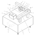
- FIG. 1 is a schematic perspective view illustrating a coating apparatus having a coating position correction function according to the embodiment.
- the coating apparatus 1 of the embodiment mainly includes a driving device 2, an imaging device 9, a linear motion device 10, a control device 12, a stage 15, and a discharge device 16.
- the direction of reference numeral 6 in the figure is referred to as the X direction
- the direction of reference numeral 7 is referred to as the Y direction
- the direction of reference numeral 8 is referred to as the Z direction.
- the drive device 2 includes an X-axis drive device 3, a Y-axis drive device 4, and a Z-axis drive device 5.
- the head unit (the linear motion device 10 and the imaging device 9 and the ejection device 16 attached to the linear motion device 10) It is a device that moves in the XYZ directions on the substrate 14.
- the driving device 2 for example, a servo motor, a combination of a stepping motor and a ball screw, a linear motor, or the like can be used.
- the substrate 14 on which the application target 13 is disposed is set at a fixed position, and the drive device 2 is relatively moved on the substrate 14. However, the drive device 2 and the application target 13 are relatively moved in the XYZ directions.
- an XY axis drive device may be provided under the stage 15 on which the substrate 14 is placed, a portal frame may be installed across the gate frame, and a Z axis drive device may be provided on the portal frame.
- the imaging device 9 is a device for imaging the application target 13 itself or an identification mark (also referred to as an alignment mark) attached on the substrate 14 on which the application target 13 is arranged. In order to perform image processing after capturing an image, it is preferable to use a digital camera using a CCD or CMOS.
- the imaging device 9 is arranged in parallel with the linear motion device 10 so as to keep a certain distance from the ejection device 16 and so that the imaging center of the imaging device 9 and the liquid outlet center of the ejection device 16 are aligned on one straight line.
- the direction in which the imaging device 9 and the discharge device 16 are arranged is made to coincide with the movement direction (reference numeral 11) of the linear motion device 10 to be described later.
- the linear motion device 10 is a device that integrally reciprocates the imaging device 9 and the ejection device 16 disposed on the side surface of the rectangular mounting portion in the X direction.
- the linear motion device 10 has a first position in which an X-direction stroke that moves toward the Y-axis drive device 4 is secured, and a second position in which the X-direction stroke is not secured.
- the linear motion device 10 can be constituted by, for example, an attachment portion connected to an air cylinder driven by a piston by the action of compressed gas, and the imaging device 9 and the discharge device 16 are attached to the side surface of the attachment portion.
- the imaging center of the imaging device 9 and the ejection port center of the ejection device 16 are installed so as to be located on the same straight line in the X direction (reference numeral 6).
- the movement of the imaging device 9 and the discharge port device 16 by the linear motion device 10 is an error that is small enough to be ignored even if it does not include a positional deviation.
- the stroke of the linear motion device 10 is equal to or longer than the distance (preferably the distance between the imaging center and the ejection port center) between the imaging device 9 and the ejection device 16 and shorter than the stroke of the driving device 2 (preferably The distance is less than half, more preferably less than one third.
- the moving direction of the linear motion device 10 is parallel to one of the moving directions of the driving device 2, that is, the X direction or the Y direction.
- the driving device 2 is parallel to the X direction (reference numeral 6).
- the X direction (symbol 6) and the direction in which the imaging device 9 and the ejection device 16 are arranged in parallel are parallel. Therefore, these three directions, that is, the moving direction of the linear motion device 10 (reference numeral 11), the direction in which the imaging device 9 and the ejection device 16 are arranged in parallel, and the X direction (one moving direction of the driving device 2) ( Reference numerals 6) are parallel to each other.
- a single image pickup device performs displacement measurement at the first image pickup position and the second image pickup position, and the difference between these measurement results is taken to obtain absolute positioning accuracy. It is possible to perform accurate position correction with minimal influence.
- the coating device 1 of the embodiment includes a control device 12 for controlling each of the above devices.
- the control device 12 includes a display device for displaying an image captured by the imaging device 9, an input device for inputting setting values, a storage device for storing data such as images and setting values, and various processes such as image processing.
- the processing apparatus which performs is provided.
- the control device 12 for example, a personal computer, a touch panel, a programmable controller, or the like can be used.
- the control device 12 may be provided inside the gantry 17 of the coating device 1.
- the coating apparatus 1 of the embodiment includes a stage 15 that supports and fixes a substrate 14 on which a coating target 13 is placed from below.
- a method of making a plurality of holes leading from the inside of the stage 15 to the upper surface and sucking and fixing the air by sucking air from the holes, and sandwiching the substrate 14 with a fixing member A method of fixing the substrate 14 by fixing the member to the stage 14 with fixing means such as a screw can be used.
- a discharge device 16 for discharging the liquid material is provided in parallel with the imaging device 9 on the side surface of the linear motion device 10.
- the discharge device 16 of this embodiment having one discharge port is detachably attached to the linear motion device 10 and can be removed for maintenance or exchanged with another type of discharge device.
- any type of discharge device such as an air type, a jet type, a plunger type, or a screw type can be used.
- the discharge device 16 includes one that can remove only the nozzle portion from the main body.
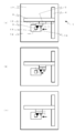
- FIG. 2 is an explanatory diagram of a coating position correction process in the coating apparatus according to the embodiment.
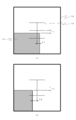
- FIG. 3 shows an image displayed in the coating position correction process in the coating apparatus according to the embodiment.
- a line intersecting the cross at the center of the image 18 and a square line (reference numeral 19) surrounding the cross represent the center of the image displayed by the imaging device (in other words, the center of the imaging device).
- the coordinates (Xa, Ya) of the head portion where the imaging center of the imaging device 9 is located at the corner (upper right) of the application target 13 disposed on the substrate 14 are referred to as “correction positions”.
- the correction position is not limited to this, and may be a characteristic part with a clear contrast that is easy to recognize an image.
- the correction position may be an identification mark on the substrate 14 or a temporary position for correction.
- the hit application point may be used as a correction position.
- the application position correction process for one application object 13 is executed as follows. ⁇ First Step> The head unit including the imaging device 9 is moved to the correction position (Xa, Ya) by the driving device 2 while the linear motion device 10 is in a stopped state (see FIG. 2A). ). The position of the head unit after this movement is taken as the first imaging position. Actually, the coordinates of the first imaging position are (Xa ′, Ya ′) because the displacement of the driving device 2 is included. In the first step, the linear motion device 10 is set to the first position where an X-direction stroke for moving toward the Y-axis drive device 4 on the substrate 14 is secured in the next step. Note that the position coordinates of the movement destination of the head unit may be set in advance in the control device 12 by performing teaching using the base substrate 14 or inputting a design value.
- ⁇ Second Step> The corner (upper right) of the application target 13 is imaged by the imaging device 9 at the first imaging position (Xa ′, Ya ′) (see FIG. 3A). Looking at this image 18 (FIG. 3A), the corner (upper right) of the application target 13 is shifted by (X1, Y1) from the center of the image at the set position.
- This displacement is a displacement due to the absolute positioning accuracy of the drive device 2 measured at the first imaging position (however, this displacement includes a displacement when the substrate 14 is placed on the stage 15. .)
- the deviation values (X1, Y1) from the center of the image are measured by image processing and stored in the control device 12.
- the linear motion device 10 causes the imaging device 9 to be in the position immediately before the ejection device 16 (position in FIG. 2A) (X direction (reference numeral 11)).
- the head is moved in the right direction in FIG. 2 (see FIG. 2B).
- the linear motion device 10 causes the head portion to approach the Y-axis drive device 4 by the installation interval (X 0 , Y 0 ) between the imaging device 9 and the ejection device 16 (reference numeral 11, FIG. 2 (rightward direction of 2) (Xa ′ + X 0 , Ya ′ + Y 0 ).
- the linear motion device 10 is in the second position where the X-direction stroke that moves toward the Y-axis drive device 4 is not secured.
- the second imaging position (Xa ′′, Ya ′′) is obtained from the position (Xa ′ + X 0 , Ya ′ + Y 0 ) of the head portion in the third step by the driving device 2 from the imaging device 9 and the ejection device.
- the position is the position where the head portion is moved in the X direction (reference numeral 11, the left direction in FIG. 2) away from the Y-axis drive device 4 by the installation interval (X 0 , Y 0 ) of 16.
- the position coordinates of the movement destination of the head unit are set in the control device 12 in advance, similarly to the first imaging position. During this movement, the head portion is prevented from moving in the Y direction (reference numeral 7).
- ⁇ Fifth Step> The corner (upper right) of the application target 13 is imaged by the imaging device 9 at the second imaging position (Xa ′′, Ya ′′) (see FIG. 3B). Looking at this image 18 (FIG. 3B), the corner of the application target 13 is shifted by (X2, Y2) from the center of the image at the set position. However, since the head unit including the imaging device 9 has not moved in the Y direction (reference numeral 7), Y2 is equal to Y1. This displacement is a displacement due to the absolute positioning accuracy of the drive device 2 measured at the second imaging position (however, this displacement includes a displacement when the substrate 14 is placed on the stage 15. .) The deviation value (X2, Y2) from the center of the image is measured by image processing and stored in the control device 12.
- the imaging center of the imaging device 9 and the ejection port center of the ejection device 16 are on the same straight line in the X direction (symbol 6), the shift amount (X1-X2) in the X direction (symbol 6). ) Can be obtained. Further, since the deviation when the substrate 14 is placed on the stage 15 disappears by the above subtraction, the calculation result is only the positional deviation amount due to the absolute positioning accuracy of the driving device 2.
- the application position is corrected by setting the position coordinates taking the correction amount into account as the application start position.
- the application position correction process described above is preferably executed before the application work in order to use the measured displacement amount as a correction value at the time of application.
- the above-described application position correction process is repeatedly executed.
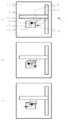
- FIG. 4 is an explanatory diagram of another coating position correction process in the coating apparatus according to the embodiment.
- the head portion does not move in the Y direction (reference numeral 7), as in FIG. ⁇ First Step>
- the image pickup device 9 is moved to the aforementioned correction position by the drive device 2 while the linear motion device 10 is stopped (see FIG. 4A).
- the position (Xa ′, Ya ′) of the head part after this movement is taken as the first imaging position.
- the linear motion device 10 is set to the first position in which the X-direction stroke for moving toward the Y-axis drive device 4 on the substrate 14 is secured in the next step.
- ⁇ Third Step> By driving the X-axis driving device 3 of the driving device 2 while the linear motion device 10 is in a stopped state, the ejection device 16 is positioned immediately before the imaging device 9 (the position shown in FIG. 4A). ) Is moved in the X direction (reference numeral 11, left direction in FIG. 4) (see FIG. 4B). The linear motion device 10 remains in the first position where the X-direction stroke is secured.
- ⁇ Fourth Step> With the drive device 2 in the stopped state, the linear motion device 10 moves the imaging device 9 to the current position of the discharge device 16 in the X direction (reference numeral 11, right direction in FIG. 4) (FIG. 4). 4 (c)). The position of the head part after this movement is defined as a second imaging position (Xa ′′, Ya ′′). The linear motion device 10 is in the second position where the X-direction stroke is not secured.
- ⁇ Fifth Step> At the second imaging position (Xa ′′, Ya ′′), the imaging device 9 images the corner (upper right) of the application target 13, and the deviation value (X2, Y2) from the image center. ) Is measured by image processing and stored in the control device 12.
- ⁇ Sixth and Seventh Steps> The procedure for calculating the positional deviation amount based on the absolute positioning accuracy of the driving device 2 at the distance (X 0 , Y 0 ) between the imaging device 9 and the ejection device 16 is the same as that in FIG. Since there is, explanation is omitted.
- the positional deviation measurement is performed at the first imaging position and the second imaging position with the single imaging device 9 for the same object 13, and these measurement results are obtained.
- the linear motion device 10 By taking the difference, it is possible to minimize the influence of the absolute positioning accuracy and perform accurate application position correction.
- accurate measurement and correction can be performed without using a particularly accurate component as a component of the driving device 2 or the like. And since it is not necessary to use a highly accurate component, there also exists a merit that cost can be held down. Furthermore, even if the components of the driving device 2 are worn out due to long-term use and the accuracy is lowered, the measurement and correction with high accuracy can be performed by performing the above-described application position correction process. .
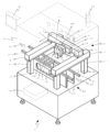
- FIG. 5 is a schematic perspective view for explaining an embodiment of a coating apparatus having a coating position correcting function.
- the coating device 1 of the example includes a discharge control device 29 and a transport device 22. , A gantry 17, a cover 26, an indicator lamp 30, a touch panel 31, and the like.
- the description of the same part as embodiment is abbreviate
- the Y-axis drive device 4 constituting the drive device 2 of the example is a two-axis having two sliders.
- the Y-axis driving device 4 biaxial as in the embodiment in order to improve accuracy.
- the accuracy may be improved by providing a guide rail parallel to the rail that supports the slider of the Y-axis drive device 4 with the Y-axis drive device 4 as one axis and supporting it at two points.
- the conveying apparatus 22 is installed over the coating device 1 full width, the drive device 2 is provided on the raising stand 21 so that this may be straddled.
- the coating apparatus 1 of an Example is provided with the conveying apparatus 22 for delivering the board
- the transport device 22 includes two support members 23 installed in parallel with substantially the same width as the substrate 14 to be transported, and a transport mechanism 24 provided above the support member 23.
- the support member 23 is a plate-like member provided with an opening, and is installed so as to stand upright on the gantry 17.
- the transport mechanism 24 rotates a belt (not shown) by rotating a roller (not shown) with a motor or the like, and transports the substrate 14 placed on the belt.
- the substrate 14 is transported by the transport mechanism 24 in the direction of the arrow indicated by reference numeral 25 (in other words, from the carry-in hole 27 to the carry-out hole 28).
- the implementation form of the transfer device 22 is not limited to the belt described above, and as an alternative means, for example, a robot having an arm may be used to deliver the substrate.
- the stage 15 is provided between the two support members 23 of the transport device 22 and has an ascending position and a descending position.
- the stage 15 is in the raised position, and the substrate 14 is supported and fixed so as to be lifted from below.
- the stage 15 takes a lowered position away from the substrate 14 so as not to contact the substrate 14.
- a combination of a motor and a ball screw, an air cylinder, or the like can be used as an apparatus for raising and lowering the stage 15.
- the substrate 14 may be fixed so as to be sandwiched between the holding member (not shown) of the transport mechanism 24 and the stage 15 at the stage raised position. .
- the substrate 14 according to the embodiment can arrange a plurality of application objects 13 in an aligned manner.
- the substrate 14 is not limited to the case where there is only one application object 13, but can be applied to a plurality of application objects 13 as illustrated. Sometimes work is done continuously.
- errors due to absolute positioning accuracy can be reduced not only for the coating object 13 alone but also for the entire substrate 14. For example, in the prior art, there was an error of about 30 ⁇ m as the application position, but it became possible to have an error of several ⁇ m by the apparatus of this example.
- the top of the coating device 1 of the coating apparatus 1 of the embodiment is covered with a cover 26 indicated by a dotted line. This is to maintain safety and prevent entry of foreign matters such as dust and dust.
- substrate 14 and the hole 28 for carrying out are vacant in both sides
- a door (not shown) is provided on the front so that the door can be opened and closed to facilitate the work on the discharge device 16 and the like in the coating device 1.
- a part of the cover 26 (for example, a front door) is formed of a transparent material such as a resin so that the inside can be seen even when the cover 26 is closed.
- a space for storing a discharge control device 29 for controlling the discharge device 16 and the like is provided in the upper and inner part of the cover 26.
- an indicator lamp 30 is provided on the upper surface of the cover 26, that is, on the ceiling, for informing the operator of the state of the apparatus 20.
- a touch panel 31 for operating the coating device 1 by connecting to the control device 12 is installed on the front side of the left side surface of the cover 26.
- the touch panel 31 functions as a part of the control device 12 as an input device for inputting data such as setting values and a display device for displaying the image 18 projected by the imaging device 9.
- the present invention not only corrects the coating position in the coating apparatus and the coating method, but also corrects the tool position when the work head device is a numerically controlled machine tool such as a lathe, a milling machine, or a drilling machine, and measures the work head device.
- the present invention can also be applied to a working apparatus and a working method that require high positional accuracy, such as position correction of a measuring instrument in the case of a device.
Landscapes
- Coating Apparatus (AREA)
- Control Of Position Or Direction (AREA)
- Length Measuring Devices By Optical Means (AREA)
- Application Of Or Painting With Fluid Materials (AREA)
- Automatic Control Of Machine Tools (AREA)
Abstract
Priority Applications (4)
| Application Number | Priority Date | Filing Date | Title |
|---|---|---|---|
| CN201380057636.3A CN104769386B (zh) | 2012-11-01 | 2013-10-30 | 具有位置修正功能的作业装置及作业方法 |
| KR1020157014448A KR102162232B1 (ko) | 2012-11-01 | 2013-10-30 | 위치 보정 기능을 가지는 작업 장치 및 작업 방법 |
| PH12015500955A PH12015500955A1 (en) | 2012-11-01 | 2015-04-29 | Work device having a position correction function, and work method |
| HK15112682.1A HK1212017A1 (en) | 2012-11-01 | 2015-12-24 | Work device having a position correction function, and work method |
Applications Claiming Priority (2)
| Application Number | Priority Date | Filing Date | Title |
|---|---|---|---|
| JP2012-241792 | 2012-11-01 | ||
| JP2012241792A JP6078298B2 (ja) | 2012-11-01 | 2012-11-01 | 位置補正機能を有する作業装置および作業方法 |
Publications (1)
| Publication Number | Publication Date |
|---|---|
| WO2014069498A1 true WO2014069498A1 (fr) | 2014-05-08 |
Family
ID=50627398
Family Applications (1)
| Application Number | Title | Priority Date | Filing Date |
|---|---|---|---|
| PCT/JP2013/079344 WO2014069498A1 (fr) | 2012-11-01 | 2013-10-30 | Dispositif de travail avec fonction de correction de position, et procédé de travail |
Country Status (8)
| Country | Link |
|---|---|
| JP (1) | JP6078298B2 (fr) |
| KR (1) | KR102162232B1 (fr) |
| CN (1) | CN104769386B (fr) |
| HK (1) | HK1212017A1 (fr) |
| MY (1) | MY173825A (fr) |
| PH (1) | PH12015500955A1 (fr) |
| TW (1) | TWI659782B (fr) |
| WO (1) | WO2014069498A1 (fr) |
Cited By (1)
| Publication number | Priority date | Publication date | Assignee | Title |
|---|---|---|---|---|
| CN110280444A (zh) * | 2019-07-03 | 2019-09-27 | 东莞京川精密机械设备有限公司 | 指纹玻璃自动贴合设备 |
Families Citing this family (12)
| Publication number | Priority date | Publication date | Assignee | Title |
|---|---|---|---|---|
| US6499060B1 (en) | 1999-03-12 | 2002-12-24 | Microsoft Corporation | Media coding for loss recovery with remotely predicted data units |
| US7003035B2 (en) | 2002-01-25 | 2006-02-21 | Microsoft Corporation | Video coding methods and apparatuses |
| US20040001546A1 (en) | 2002-06-03 | 2004-01-01 | Alexandros Tourapis | Spatiotemporal prediction for bidirectionally predictive (B) pictures and motion vector prediction for multi-picture reference motion compensation |
| US10554985B2 (en) | 2003-07-18 | 2020-02-04 | Microsoft Technology Licensing, Llc | DC coefficient signaling at small quantization step sizes |
| US7738554B2 (en) | 2003-07-18 | 2010-06-15 | Microsoft Corporation | DC coefficient signaling at small quantization step sizes |
| US8634413B2 (en) | 2004-12-30 | 2014-01-21 | Microsoft Corporation | Use of frame caching to improve packet loss recovery |
| JP6576124B2 (ja) * | 2015-07-02 | 2019-09-18 | 東京エレクトロン株式会社 | 液滴吐出装置、液滴吐出方法、プログラム及びコンピュータ記憶媒体 |
| JP2018189387A (ja) * | 2017-04-28 | 2018-11-29 | セイコーエプソン株式会社 | 電子部品搬送装置および電子部品検査装置 |
| JP6918657B2 (ja) * | 2017-09-15 | 2021-08-11 | Ntn株式会社 | 基板観察装置、塗布装置および位置決め方法 |
| JP2020008762A (ja) | 2018-07-10 | 2020-01-16 | キオクシア株式会社 | パターニング支援システム、パターニング方法、及びプログラム |
| KR102277980B1 (ko) * | 2019-07-03 | 2021-07-15 | 세메스 주식회사 | 잉크젯 프린팅 시스템 |
| CN111998852B (zh) * | 2020-07-17 | 2021-03-16 | 无锡卡尔曼导航技术有限公司 | 一种农机自动调节交接行的方法 |
Citations (7)
| Publication number | Priority date | Publication date | Assignee | Title |
|---|---|---|---|---|
| JPH1012642A (ja) * | 1996-06-26 | 1998-01-16 | Toshiba Corp | 樹脂塗布方法およびその装置 |
| JP2001176897A (ja) * | 1999-12-15 | 2001-06-29 | Hitachi Ltd | 半導体装置の製造方法および製造装置 |
| JP2003001170A (ja) * | 2001-06-26 | 2003-01-07 | Hitachi Industries Co Ltd | ペースト塗布機 |
| JP2007061734A (ja) * | 2005-08-31 | 2007-03-15 | Seiko Epson Corp | 描画装置及び描画方法 |
| JP2007178367A (ja) * | 2005-12-28 | 2007-07-12 | Shibaura Mechatronics Corp | ペーストの塗布量測定装置及びペースト塗布装置 |
| JP2010131488A (ja) * | 2008-12-03 | 2010-06-17 | Seiko Epson Corp | 液滴吐出装置及び載置板 |
| JP2012148235A (ja) * | 2011-01-19 | 2012-08-09 | Musashi Eng Co Ltd | 液体材料の塗布方法、塗布装置およびプログラム |
Family Cites Families (9)
| Publication number | Priority date | Publication date | Assignee | Title |
|---|---|---|---|---|
| JP2849320B2 (ja) | 1993-11-10 | 1999-01-20 | 日立テクノエンジニアリング株式会社 | ペースト塗布機 |
| DE10048749A1 (de) * | 2000-09-29 | 2002-04-11 | Josef Schucker | Anordnung zum Aufbringen von Klebstoff auf ein Werkstück |
| JP4333074B2 (ja) | 2002-03-07 | 2009-09-16 | 東レ株式会社 | 塗布装置および塗布方法ならびにプラズマディスプレイ部材の製造装置および製造方法 |
| JP3889347B2 (ja) | 2002-11-18 | 2007-03-07 | 芝浦メカトロニクス株式会社 | シール剤の塗布装置および塗布方法 |
| JP4371832B2 (ja) * | 2004-01-27 | 2009-11-25 | 富士機械製造株式会社 | 電子部品実装装置における移動台の移動制御方法およびその方法に用いられるマトリックス基板 |
| US7923056B2 (en) * | 2007-06-01 | 2011-04-12 | Illinois Tool Works Inc. | Method and apparatus for dispensing material on a substrate |
| CN102999782B (zh) * | 2012-11-16 | 2015-11-04 | 杭州维勘科技有限公司 | 基于图像处理的薄片计数器及计数方法 |
| CN203148383U (zh) * | 2013-03-20 | 2013-08-21 | 昆山三景科技股份有限公司 | 可视化钣金件测量系统 |
| CN103256896B (zh) * | 2013-04-19 | 2015-06-24 | 大连理工大学 | 一种高速滚转体位姿测量方法 |
-
2012
- 2012-11-01 JP JP2012241792A patent/JP6078298B2/ja active Active
-
2013
- 2013-10-30 CN CN201380057636.3A patent/CN104769386B/zh active Active
- 2013-10-30 KR KR1020157014448A patent/KR102162232B1/ko active IP Right Grant
- 2013-10-30 MY MYPI2015701373A patent/MY173825A/en unknown
- 2013-10-30 WO PCT/JP2013/079344 patent/WO2014069498A1/fr active Application Filing
- 2013-11-01 TW TW102139758A patent/TWI659782B/zh active
-
2015
- 2015-04-29 PH PH12015500955A patent/PH12015500955A1/en unknown
- 2015-12-24 HK HK15112682.1A patent/HK1212017A1/xx unknown
Patent Citations (7)
| Publication number | Priority date | Publication date | Assignee | Title |
|---|---|---|---|---|
| JPH1012642A (ja) * | 1996-06-26 | 1998-01-16 | Toshiba Corp | 樹脂塗布方法およびその装置 |
| JP2001176897A (ja) * | 1999-12-15 | 2001-06-29 | Hitachi Ltd | 半導体装置の製造方法および製造装置 |
| JP2003001170A (ja) * | 2001-06-26 | 2003-01-07 | Hitachi Industries Co Ltd | ペースト塗布機 |
| JP2007061734A (ja) * | 2005-08-31 | 2007-03-15 | Seiko Epson Corp | 描画装置及び描画方法 |
| JP2007178367A (ja) * | 2005-12-28 | 2007-07-12 | Shibaura Mechatronics Corp | ペーストの塗布量測定装置及びペースト塗布装置 |
| JP2010131488A (ja) * | 2008-12-03 | 2010-06-17 | Seiko Epson Corp | 液滴吐出装置及び載置板 |
| JP2012148235A (ja) * | 2011-01-19 | 2012-08-09 | Musashi Eng Co Ltd | 液体材料の塗布方法、塗布装置およびプログラム |
Cited By (1)
| Publication number | Priority date | Publication date | Assignee | Title |
|---|---|---|---|---|
| CN110280444A (zh) * | 2019-07-03 | 2019-09-27 | 东莞京川精密机械设备有限公司 | 指纹玻璃自动贴合设备 |
Also Published As
| Publication number | Publication date |
|---|---|
| PH12015500955B1 (en) | 2015-07-27 |
| KR20150079938A (ko) | 2015-07-08 |
| JP2014092397A (ja) | 2014-05-19 |
| HK1212017A1 (en) | 2016-06-03 |
| PH12015500955A1 (en) | 2015-07-27 |
| CN104769386B (zh) | 2017-10-20 |
| MY173825A (en) | 2020-02-24 |
| KR102162232B1 (ko) | 2020-10-06 |
| CN104769386A (zh) | 2015-07-08 |
| TWI659782B (zh) | 2019-05-21 |
| JP6078298B2 (ja) | 2017-02-08 |
| TW201429557A (zh) | 2014-08-01 |
Similar Documents
| Publication | Publication Date | Title |
|---|---|---|
| JP6078298B2 (ja) | 位置補正機能を有する作業装置および作業方法 | |
| US11395410B2 (en) | Method and apparatus for automatically adjusting dispensing units of a dispenser | |
| TWI395632B (zh) | Deformable door type operating device | |
| JP5852505B2 (ja) | 部品または基板の作業装置および部品実装装置 | |
| JP6152248B2 (ja) | ペースト塗布装置及びペースト塗布方法並びにダイボンダ | |
| JP2014140789A (ja) | 塗布システム及び塗布方法 | |
| KR101141806B1 (ko) | 도포 장치와 그 도포 위치 보정 방법 | |
| JP5171230B2 (ja) | アライメントマークの検出装置及び方法 | |
| KR101614425B1 (ko) | 기판 처리 장치 및 헤드블럭의 좌표 보정 방법 | |
| JP5047772B2 (ja) | 実装基板製造方法 | |
| JP2013207270A (ja) | 実装装置、実装位置の補正方法、プログラム及び基板の製造方法 | |
| JP2021531964A (ja) | 同期供給から非同期供給に移行するシステム及び方法 | |
| JP2006088103A (ja) | 接着剤塗布装置 | |
| JP3823049B2 (ja) | ペースト塗布機 |
Legal Events
| Date | Code | Title | Description |
|---|---|---|---|
| 121 | Ep: the epo has been informed by wipo that ep was designated in this application |
Ref document number: 13851005 Country of ref document: EP Kind code of ref document: A1 |
|
| WWE | Wipo information: entry into national phase |
Ref document number: 12015500955 Country of ref document: PH |
|
| NENP | Non-entry into the national phase |
Ref country code: DE |
|
| ENP | Entry into the national phase |
Ref document number: 20157014448 Country of ref document: KR Kind code of ref document: A |
|
| 122 | Ep: pct application non-entry in european phase |
Ref document number: 13851005 Country of ref document: EP Kind code of ref document: A1 |