WO2014069352A1 - 電子機器及び制御プログラム並びに電子機器の動作方法 - Google Patents
電子機器及び制御プログラム並びに電子機器の動作方法 Download PDFInfo
- Publication number
- WO2014069352A1 WO2014069352A1 PCT/JP2013/078924 JP2013078924W WO2014069352A1 WO 2014069352 A1 WO2014069352 A1 WO 2014069352A1 JP 2013078924 W JP2013078924 W JP 2013078924W WO 2014069352 A1 WO2014069352 A1 WO 2014069352A1
- Authority
- WO
- WIPO (PCT)
- Prior art keywords
- display
- display area
- mode
- electronic device
- cursor
- Prior art date
- Legal status (The legal status is an assumption and is not a legal conclusion. Google has not performed a legal analysis and makes no representation as to the accuracy of the status listed.)
- Ceased
Links
Images















Classifications
-
- G—PHYSICS
- G06—COMPUTING OR CALCULATING; COUNTING
- G06F—ELECTRIC DIGITAL DATA PROCESSING
- G06F3/00—Input arrangements for transferring data to be processed into a form capable of being handled by the computer; Output arrangements for transferring data from processing unit to output unit, e.g. interface arrangements
- G06F3/01—Input arrangements or combined input and output arrangements for interaction between user and computer
- G06F3/048—Interaction techniques based on graphical user interfaces [GUI]
- G06F3/0481—Interaction techniques based on graphical user interfaces [GUI] based on specific properties of the displayed interaction object or a metaphor-based environment, e.g. interaction with desktop elements like windows or icons, or assisted by a cursor's changing behaviour or appearance
- G06F3/04812—Interaction techniques based on cursor appearance or behaviour, e.g. being affected by the presence of displayed objects
-
- G—PHYSICS
- G06—COMPUTING OR CALCULATING; COUNTING
- G06F—ELECTRIC DIGITAL DATA PROCESSING
- G06F3/00—Input arrangements for transferring data to be processed into a form capable of being handled by the computer; Output arrangements for transferring data from processing unit to output unit, e.g. interface arrangements
- G06F3/01—Input arrangements or combined input and output arrangements for interaction between user and computer
- G06F3/048—Interaction techniques based on graphical user interfaces [GUI]
- G06F3/0487—Interaction techniques based on graphical user interfaces [GUI] using specific features provided by the input device, e.g. functions controlled by the rotation of a mouse with dual sensing arrangements, or of the nature of the input device, e.g. tap gestures based on pressure sensed by a digitiser
- G06F3/0488—Interaction techniques based on graphical user interfaces [GUI] using specific features provided by the input device, e.g. functions controlled by the rotation of a mouse with dual sensing arrangements, or of the nature of the input device, e.g. tap gestures based on pressure sensed by a digitiser using a touch-screen or digitiser, e.g. input of commands through traced gestures
-
- G—PHYSICS
- G06—COMPUTING OR CALCULATING; COUNTING
- G06F—ELECTRIC DIGITAL DATA PROCESSING
- G06F3/00—Input arrangements for transferring data to be processed into a form capable of being handled by the computer; Output arrangements for transferring data from processing unit to output unit, e.g. interface arrangements
- G06F3/01—Input arrangements or combined input and output arrangements for interaction between user and computer
- G06F3/03—Arrangements for converting the position or the displacement of a member into a coded form
- G06F3/033—Pointing devices displaced or positioned by the user, e.g. mice, trackballs, pens or joysticks; Accessories therefor
- G06F3/038—Control and interface arrangements therefor, e.g. drivers or device-embedded control circuitry
-
- G—PHYSICS
- G06—COMPUTING OR CALCULATING; COUNTING
- G06F—ELECTRIC DIGITAL DATA PROCESSING
- G06F3/00—Input arrangements for transferring data to be processed into a form capable of being handled by the computer; Output arrangements for transferring data from processing unit to output unit, e.g. interface arrangements
- G06F3/01—Input arrangements or combined input and output arrangements for interaction between user and computer
- G06F3/048—Interaction techniques based on graphical user interfaces [GUI]
- G06F3/0484—Interaction techniques based on graphical user interfaces [GUI] for the control of specific functions or operations, e.g. selecting or manipulating an object, an image or a displayed text element, setting a parameter value or selecting a range
- G06F3/04847—Interaction techniques to control parameter settings, e.g. interaction with sliders or dials
-
- G—PHYSICS
- G06—COMPUTING OR CALCULATING; COUNTING
- G06F—ELECTRIC DIGITAL DATA PROCESSING
- G06F3/00—Input arrangements for transferring data to be processed into a form capable of being handled by the computer; Output arrangements for transferring data from processing unit to output unit, e.g. interface arrangements
- G06F3/01—Input arrangements or combined input and output arrangements for interaction between user and computer
- G06F3/048—Interaction techniques based on graphical user interfaces [GUI]
- G06F3/0484—Interaction techniques based on graphical user interfaces [GUI] for the control of specific functions or operations, e.g. selecting or manipulating an object, an image or a displayed text element, setting a parameter value or selecting a range
- G06F3/0485—Scrolling or panning
-
- G—PHYSICS
- G06—COMPUTING OR CALCULATING; COUNTING
- G06F—ELECTRIC DIGITAL DATA PROCESSING
- G06F3/00—Input arrangements for transferring data to be processed into a form capable of being handled by the computer; Output arrangements for transferring data from processing unit to output unit, e.g. interface arrangements
- G06F3/01—Input arrangements or combined input and output arrangements for interaction between user and computer
- G06F3/048—Interaction techniques based on graphical user interfaces [GUI]
- G06F3/0487—Interaction techniques based on graphical user interfaces [GUI] using specific features provided by the input device, e.g. functions controlled by the rotation of a mouse with dual sensing arrangements, or of the nature of the input device, e.g. tap gestures based on pressure sensed by a digitiser
- G06F3/0488—Interaction techniques based on graphical user interfaces [GUI] using specific features provided by the input device, e.g. functions controlled by the rotation of a mouse with dual sensing arrangements, or of the nature of the input device, e.g. tap gestures based on pressure sensed by a digitiser using a touch-screen or digitiser, e.g. input of commands through traced gestures
- G06F3/04883—Interaction techniques based on graphical user interfaces [GUI] using specific features provided by the input device, e.g. functions controlled by the rotation of a mouse with dual sensing arrangements, or of the nature of the input device, e.g. tap gestures based on pressure sensed by a digitiser using a touch-screen or digitiser, e.g. input of commands through traced gestures for inputting data by handwriting, e.g. gesture or text
-
- G—PHYSICS
- G06—COMPUTING OR CALCULATING; COUNTING
- G06F—ELECTRIC DIGITAL DATA PROCESSING
- G06F3/00—Input arrangements for transferring data to be processed into a form capable of being handled by the computer; Output arrangements for transferring data from processing unit to output unit, e.g. interface arrangements
- G06F3/01—Input arrangements or combined input and output arrangements for interaction between user and computer
- G06F3/048—Interaction techniques based on graphical user interfaces [GUI]
- G06F3/0487—Interaction techniques based on graphical user interfaces [GUI] using specific features provided by the input device, e.g. functions controlled by the rotation of a mouse with dual sensing arrangements, or of the nature of the input device, e.g. tap gestures based on pressure sensed by a digitiser
- G06F3/0488—Interaction techniques based on graphical user interfaces [GUI] using specific features provided by the input device, e.g. functions controlled by the rotation of a mouse with dual sensing arrangements, or of the nature of the input device, e.g. tap gestures based on pressure sensed by a digitiser using a touch-screen or digitiser, e.g. input of commands through traced gestures
- G06F3/04886—Interaction techniques based on graphical user interfaces [GUI] using specific features provided by the input device, e.g. functions controlled by the rotation of a mouse with dual sensing arrangements, or of the nature of the input device, e.g. tap gestures based on pressure sensed by a digitiser using a touch-screen or digitiser, e.g. input of commands through traced gestures by partitioning the display area of the touch-screen or the surface of the digitising tablet into independently controllable areas, e.g. virtual keyboards or menus
-
- G—PHYSICS
- G06—COMPUTING OR CALCULATING; COUNTING
- G06F—ELECTRIC DIGITAL DATA PROCESSING
- G06F2203/00—Indexing scheme relating to G06F3/00 - G06F3/048
- G06F2203/048—Indexing scheme relating to G06F3/048
- G06F2203/04801—Cursor retrieval aid, i.e. visual aspect modification, blinking, colour changes, enlargement or other visual cues, for helping user do find the cursor in graphical user interfaces
Definitions
- the present invention relates to an electronic device.
- the present invention has been made in view of the above-described points, and an object thereof is to provide a technique that makes it possible to improve the operability of an electronic device.
- An electronic device includes: a determination unit that determines an operation mode of the electronic device; a display unit that performs display in a display region; a detection unit that detects an operation by an operator for the display region; and the display region.
- a process execution unit that executes a process associated with the displayed display target, and the determination unit detects the first operation by the operator with respect to the display area when the detection unit detects the operation mode. Is determined as a cursor display mode in which a cursor is displayed in the display region, and the display unit detects the operation element in the display region detected by the detection unit when the operation mode is the cursor display mode.
- the cursor is moved in the display area according to the movement of the display area, and the processing execution unit moves the cursor in the display area when the operation mode is the cursor display mode.
- the detection unit detects that the operator has moved away from the display area after moving in the display area so that the cursor points to the display target, the processing associated with the display target pointed to by the cursor is executed. To do.
- the control program is a control program for controlling an electronic device having a display area, and when the electronic device detects (a) a first operation of an operator for the display area. Determining the operation mode of the electronic device as a cursor display mode in which a cursor is displayed in the display area; and (b) detecting the detection unit when the operation mode is the cursor display mode. A step of moving a cursor in the display area according to the movement of the operation element in the display area; and (c) when the operation mode is the cursor display mode, the cursor indicates a display target in the display area. When it is detected that the operator has moved away from the display area after moving in the display area, the cursor points It is intended for executing the step of executing the processing related to indicate the subject.
- the operation method of the electronic device is an operation method of the electronic device having a display area, and (a) the operation of the electronic device is detected when the first operation of the operator with respect to the display area is detected. Determining a mode as a cursor display mode in which a cursor is displayed in the display area; and (b) the operation in the display area detected by the detection unit when the operation mode is the cursor display mode. (C) when the operation mode is the cursor display mode, the operation element is moved so that the cursor points to a display target in the display area when the operation mode is the cursor display mode. When it is detected that the user has left the display area after moving in the display area, the process associated with the display target indicated by the cursor is executed. And a step of.
- the operability of the electronic device is improved.
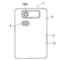
- ⁇ Appearance of electronic equipment> 1 and 2 are a front view and a back view, respectively, showing the appearance of the electronic apparatus 1 according to the embodiment.
- Electronic device 1 according to the present embodiment is a mobile phone, for example.
- the electronic device 1 can communicate with other communication devices through a base station, a server, and the like.
- the electronic device 1 includes a cover panel 2 and a case portion 3.
- a device case 4 having a substantially rectangular plate shape in plan view is configured.
- the cover panel 2 has a substantially rectangular shape in plan view.
- the cover panel 2 constitutes a part other than the peripheral part in the front part of the electronic device 1.
- the cover panel 2 is made of, for example, transparent glass or transparent acrylic resin.
- the case part 3 constitutes a peripheral part, a side part and a back part of the front part of the electronic device 1.
- the case portion 3 is made of, for example, polycarbonate resin.
- a display area 2a for displaying various information such as characters, symbols and figures.
- the display area 2a has a rectangular shape in plan view, for example.
- the peripheral part 2b surrounding the display area 2a in the cover panel 2 is black, for example, by applying a film or the like. Thereby, the peripheral part 2b is a non-display part where information is not displayed.
- a touch panel 130 described later is attached to the back surface of the cover panel 2.
- the user can give various instructions to the electronic device 1 by operating the display area 2a on the front surface of the electronic device 1 with a finger or the like.
- the user can also give various instructions to the electronic device 1 by operating the display area 2a with an operator other than a finger, for example, an electrostatic touch panel pen such as a stylus pen.
- a home key 5a, a menu key 5b, and a back key 5c are provided.
- Each of the home key 5a, the menu key 5b, and the back key 5c is a hardware key.
- Each surface of the home key 5a, the menu key 5b, and the back key 5c is exposed from the lower end of the front surface of the cover panel 2.
- the home key 5a is an operation key for displaying a home screen (initial screen) in the display area 2a.
- the menu key 5b is an operation key for displaying an option menu screen.
- the back key 5c is an operation key for returning the display of the display area 2a to the previous display.
- each of the home key 5a, the menu key 5b, and the back key 5c is referred to as an “operation key 5”.
- each of the home key 5a, the menu key 5b, and the back key 5c may be a software key that is displayed on the display area 2a and an operation on the touch panel 130 is detected instead of the hardware key.
- a microphone hole 6 is formed at the lower end of the cover panel 2.
- a receiver hole 7 is formed in the upper end portion of the cover panel 2.
- An imaging lens 180 a included in a front-side imaging unit 180 described later is visible from the upper end portion of the front surface of the cover panel 2.
- speaker holes 8 are formed on the back surface of the electronic device 1, in other words, on the back surface of the device case 4. And from the back surface of the electronic device 1, the imaging lens 190a which the back surface side imaging part 190 mentioned later has becomes visible.
- FIG. 3 is a block diagram showing an electrical configuration of the electronic apparatus 1.
- the electronic device 1 includes a control unit 100, a wireless communication unit 110, a display panel 120, a touch panel 130, and a key operation detection unit 140. Further, the electronic device 1 is provided with a microphone 150, a receiver 160, an external speaker 170, a front side imaging unit 180, a back side imaging unit 190, and a battery 200. These components provided in the electronic device 1 are housed in the device case 4.
- the control unit 100 includes a CPU (Central Processing Unit) 101, a DSP (Digital Signal Processing) 102, a storage unit 103, and the like.
- the control unit 100 comprehensively manages the operation of the electronic device 1 by controlling other components of the electronic device 1.
- the storage unit 103 is configured by a non-transitory recording medium that can be read by the electronic device 1 (CPU 101 and DPS 102), such as a ROM (Read Only Memory) and a RAM (Random Access Memory).
- the storage unit 103 may include a computer-readable non-transitory recording medium other than the ROM and RAM.
- the storage unit 103 may include, for example, a hard disk drive, an SSD (Solid State Drive), a USB (Universal Serial Bus) memory, or the like.
- the storage unit 103 includes a main program 103a that is a control program for controlling the operation of the electronic device 1, specifically, the wireless communication unit 110 and the display panel 120 included in the electronic device 1, and a plurality of applications.
- a program 103b and the like are stored.
- Various functions of the control unit 100 are realized by the CPU 101 and the DSP 102 executing various programs in the storage unit 103. In FIG. 3, only one application program 103b is shown in order to avoid the complexity of the drawing.
- the wireless communication unit 110 has an antenna 111.
- the wireless communication unit 110 receives a signal from a communication device such as a mobile phone different from the electronic device 1 or a web server connected to the Internet via the base station or the like via the antenna 111.
- Radio communication unit 110 performs amplification processing and down-conversion on the received signal and outputs the result to control unit 100.
- the control unit 100 performs demodulation processing or the like on the input reception signal, and acquires a sound signal indicating voice or music included in the reception signal. Further, the wireless communication unit 110 performs up-conversion and amplification processing on the transmission signal including the sound signal and the like generated by the control unit 100, and wirelessly transmits the processed transmission signal from the antenna 111.
- a transmission signal from the antenna 111 is received through a base station or the like by a mobile phone different from the electronic device 1 or a communication device connected to the Internet.
- the display panel 120 is, for example, a liquid crystal display panel or an organic EL panel.
- the display panel 120 displays various types of information such as characters, symbols, and graphics under the control of the control unit 100.
- Information displayed on the display panel 120 is displayed in the display area 2 a on the front surface of the cover panel 2. Therefore, it can be said that the display panel 120 is displaying in the display area 2a.
- the touch panel 130 detects an operation by an operator such as a finger on the display area 2 a of the cover panel 2.
- the touch panel 130 is a projected capacitive touch panel, for example, and is attached to the back surface of the cover panel 2.
- a signal corresponding to the operation is input from the touch panel 130 to the control unit 100.
- the control unit 100 Based on the signal from the touch panel 130, the control unit 100 identifies the content of the operation performed on the display area 2a, and performs processing according to the content.
- touch panel 130 since the detection sensitivity is set high, not only the operation element is in contact with display area 2a but also the distance from display area 2a is a predetermined distance. In the following, it can also be detected that the operator is close to the display area 2a. That is, the detection sensitivity of the touch panel 130 is set so that the touch panel 130 reacts when the distance between the display area 2a and the operation element is equal to or less than a predetermined distance. Therefore, the touch panel 130 not only leaves the operator in contact with the display area 2a away from the display area 2a, but also places the operator close to the display area 2a with a distance from the display area 2a being a predetermined distance or less. However, it can also be detected that the distance from the display area 2a is larger than the predetermined distance.
- the distance from the display area 2a is equal to or less than the predetermined distance and the operation element is close to the display area 2a, that is, the touch panel 130 reacts.
- the control is close to the display area 2a until
- the operator is not only separated from the display area 2a, but the operator that is in contact with the display area 2a is not only separated from the display area 2a, but the distance from the display area 2a is It is assumed that the operator close to the display area 2a at a predetermined distance or less moves away from the display area 2a so that the distance to the display area 2a is larger than the predetermined distance.
- the key operation detection unit 140 detects a user's pressing operation on each operation key 5.
- the key operation detection unit 140 detects, for each operation key 5, whether or not the operation key 5 is pressed (operated). When the operation key 5 is not pressed, the key operation detection unit 140 outputs a non-operation signal indicating that the operation key 5 is not operated to the control unit 100. Further, when the operation key 5 is pressed, the key operation detection unit 140 outputs an operation signal indicating that the operation key 5 has been operated to the control unit 100. Thereby, the control part 100 can judge whether the said operation key 5 is operated about each operation key 5.
- the control unit 100 displays the home screen (initial screen) on the display panel 120 when the key operation detection unit 140 detects that the home key 5a is pressed and then not pressed. As a result, the home screen is displayed in the display area 2a.
- the control unit 100 causes the display panel 120 to display an option menu screen. Thereby, the option menu screen is displayed in the display area 2a.
- the control unit 100 causes the display panel 120 to return the display to the previous one. Thereby, the display of the display area 2a returns to the previous one.
- the microphone 150 converts sound input from the outside of the electronic device 1 into an electrical sound signal and outputs the electrical sound signal to the control unit 100. Sound from the outside of the electronic device 1 is taken into the electronic device 1 from the microphone hole 6 provided on the front surface of the cover panel 2 and input to the microphone 150.
- the external speaker 170 is, for example, a dynamic speaker.
- the external speaker 170 converts the electrical sound signal from the control unit 100 into sound and outputs the sound.
- the sound output from the external speaker 170 is output to the outside from the speaker hole 8 provided on the back surface of the electronic device 1.
- the sound output from the speaker hole 8 can be heard at a place away from the electronic device 1.
- the front side imaging unit 180 includes an imaging lens 180a and an imaging element.
- the front-side imaging unit 180 captures still images and moving images based on control by the control unit 100. As shown in FIG. 1, since the imaging lens 180 a is provided on the front surface of the electronic device 1, the front-side imaging unit 180 detects an object present on the front surface side (cover panel 2 side) of the electronic device 1. It is possible to image.
- the back side imaging unit 190 includes an imaging lens 190a and an imaging element.
- the back side imaging unit 190 captures still images and moving images based on control by the control unit 100. As shown in FIG. 2, since the imaging lens 190 a is provided on the back surface of the electronic device 1, the back surface side imaging unit 190 can image an object existing on the back surface 10 side of the electronic device 1. It is.
- the receiver 160 outputs a received sound.
- the receiver 160 is composed of, for example, a dynamic speaker.
- the receiver 160 converts the electrical sound signal from the control unit 100 into sound and outputs the sound.
- the sound output from the receiver 160 is output to the outside from the receiver hole 7 provided on the front surface of the electronic device 1.
- the volume of the sound output from the receiver hole 7 is smaller than the volume of the sound output from the speaker hole 8.
- the battery 200 outputs the power source of the electronic device 1.
- the power output from the battery 200 is supplied to each electronic component included in the control unit 100 and the wireless communication unit 110 included in the electronic device 1.
- the storage unit 103 stores various application programs 103b (hereinafter simply referred to as “applications 103b”).
- the storage unit 103 stores, for example, a telephone application for making a call using a telephone function, a browser for displaying a website, and a mail application for creating, browsing, and transmitting / receiving e-mails.
- the storage unit 103 stores a television application for viewing and recording a television program, a moving image reproduction control application for controlling reproduction of moving image data stored in the storage unit 103, and the storage unit 103.
- a music playback control application for performing playback control of the music data being stored is stored.
- the control unit 100 When the control unit 100 executing the main program 103a in the storage unit 103 reads and executes the application 103b in the storage unit 103, the control unit 100 includes the wireless communication unit 110, the display panel 120, the receiver 160, and the like. The other components in the electronic device 1 are controlled, whereby the function (processing) corresponding to the application 103b is executed in the electronic device 1.
- the control unit 100 executing the telephone application controls the wireless communication unit 110, the microphone 150, and the receiver 160.
- the audio included in the reception signal received by the wireless communication unit 110 is output from the receiver 160, and the transmission signal including the audio input to the microphone 150 is transmitted from the wireless communication unit 110.
- a call using the telephone function is performed with the communication partner apparatus.
- Examples of basic operations that the user performs on the display area 2a include a slide operation, a tap operation, and a flick operation.
- the slide operation is an operation in which an operator such as a finger moves while in contact with or close to the display area 2a. That is, the slide operation is an operation in which the operator moves in the display area 2a.
- the user can, for example, scroll the display of the display area 2a or switch the page displayed in the display area 2a to another page by performing a slide operation on the display area 2a.
- the operation in which the operating element moves in the display area 2a includes an operation in which the operating element moves in contact with the display area 2a and a state in which the operating element is in proximity to the display area 2a. Includes both moving operations.
- the tap operation is an operation of leaving the display area 2a immediately after the operator touches or approaches the display area 2a.
- the tap operation is an operation of leaving the display area 2a at the contact position or the proximity position within a predetermined time after the operator touches or approaches the display area 2a.
- the user selects, for example, an application icon (hereinafter referred to as “application icon”) for executing the application 103b displayed in the display area 2a.
- the application 103b can be executed by the electronic device 1.
- the flick operation is an operation for paying the display area 2a with an operator.
- the flick operation is an operation in which the operation element moves beyond a predetermined distance within a predetermined time and leaves the display area 2a while being in contact with or close to the display area 2a.
- the user performs a flick operation on the display area 2a, for example, scrolls the display of the display area 2a in the direction of the flick operation, or switches the page displayed in the display area 2a to another page. can do.
- FIG. 4 and 5 are diagrams illustrating an example of a state in which the user operates the electronic device 1.
- FIG. 4 shows a state where the user holds the electronic device 1 in the left hand 20 and operates the display area 2 a with the thumb 21 of the left hand 20.
- FIG. 5 shows a state in which the user holds the electronic device 1 in the right hand 30 and operates the display area 2 a with the thumb 31 of the right hand 30.
- the user when the user holds the electronic device 1 with one hand and operates the display area 2a with the thumb, the user may have difficulty operating the end of the display area 2a. Specifically, it may be difficult for the user to select a display target such as an application icon or a link in a web page (also referred to as “hyperlink”) displayed at the end of the display area 2a with the thumb. This problem becomes conspicuous as the display area 2a becomes larger and the screen becomes larger.
- the electronic apparatus 1 can display a cursor (pointer) similar to a mouse cursor (also referred to as “mouse pointer”) used in a personal computer or the like in the display area 2a.
- the user can move the cursor in the display area 2a by operating the display area 2a. Thereby, even when the user operates the electronic device 1 with one hand as shown in FIGS. 4 and 5, the user can easily operate the electronic device 1. This point will be described in detail below.
- Electronic device 1 includes a cursor display mode, an enlargement / reduction mode, and a selection mode as operation modes.
- the cursor display mode is a mode in which a cursor is displayed in the display area 2a.
- the enlargement / reduction mode is a mode in which the display in the display area 2a is enlarged or reduced.
- the selection mode is a mode for selecting a mode as an operation mode of the electronic device 1 from the cursor display mode and the enlargement / reduction mode.
- a state in which the electronic device 1 is not operating in the cursor display mode, the enlargement / reduction mode, and the selection mode is referred to as a “normal mode”.
- the control unit 100 functions as an operation mode determination unit that determines the operation mode of the electronic device 1. When the operation mode is the normal mode and the predetermined operation is performed on the display area 2a, the control unit 100 sets the operation mode to the selection mode. When the operation mode is the selection mode, the electronic device 1 sets the operation mode to the cursor display mode or the enlargement / reduction mode according to the operation on the display area 2a.
- each operation mode of the electronic device 1 will be described mainly by taking as an example the case where a web page is displayed in the display area 2a. The same can be said for the following description even when a web page other than the web page is displayed in the display area 2a.
- FIG. 5 assuming that the user holds the electronic device 1 in the right hand 30 and operates the display area 2 a with the thumb 31 of the right hand 30, A thumb of the right hand of the user is shown as an operator 60 for operating the display area 2a. The same can be said for the following description even if the operation element 60 is other.
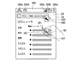
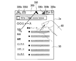
- FIG. 6 is a diagram illustrating an example of a state in which a web page is displayed in the display area 2a.
- a web page 50 showing news information is displayed in the display area 2a.
- the web page 50 includes a plurality of links (hyperlinks).
- the links in the web page 50 are underlined.
- the control unit 100 that executes the browser in the storage unit 103 acquires the web page 50 from the web server through the wireless communication unit 110. Then, when the control unit 100 controls the display panel 120, the web page 50 is displayed in the display area 2a.
- information indicating the state of the electronic device 1 is displayed in the display area 2a.
- the upper end portion 300 of the display area 2 a has, as information indicating the state of the electronic device 1, an icon (graphic) for notifying the current time 300 a measured by the electronic device 1 and the remaining battery level. ) 300b and an icon 300c for notifying the communication state are displayed.
- the control unit 100 detects that a specific event has occurred in the electronic device 1, the control unit 100 controls the display panel 120 to display information related to the event in the display area 2a.
- the upper end portion 300 of the display area 2 a has an icon 300 d for notifying the occurrence of an event that a new e-mail has been received as information about an event that has occurred in the electronic device 1, and an event that is a missed call.
- An icon 300e for notifying the occurrence is displayed.
- the display of the display area 2a when the display of the display area 2a is in an on state, information indicating the state of the electronic device 1 is displayed on the upper end portion 300 of the display area 2a except that a specific part of the application 103b is being executed. Is always displayed.
- information indicating the state of the electronic device 1 is displayed on the upper end portion 300 of the display area 2a
- a specific event occurs in the electronic device 1
- information on the event is also displayed on the upper end portion 300. Is done.
- the upper end portion 300 on which information indicating the state of the electronic device 1 is displayed in the display area 2a is particularly referred to as a “notification area 300”.
- This notification area 300 is called a “pict area”.
- the touch panel 130 has been tapped with the operator 60 on the portion of the display area 2a where the link included in the web page 50 is displayed. Is detected, the control unit 100 determines that the link has been selected by the user. And the control part 100 acquires the web page which the said link shows from the said web server by communicating with a relevant web server through the wireless communication part 110.
- FIG. The display panel 120 displays the web page acquired by the control unit 100 in the display area 2a under the control of the control unit 100.
- control unit 100 and the display panel 120 function as a process execution unit that executes a process associated with a link that is one of the display targets displayed in the display area 2a.
- the link is associated with processing for acquiring and displaying the web page indicated by the link.
- the touch panel 130 performs a tap operation by the operator 60 on a part of the display area 2a other than the part where the notification area 300 and the link are displayed.
- the display panel 120 displays the display area 2a based on the tapped portion of the display area 2a as a base point (center) under the control of the control unit 100. Expanding. Two consecutive tap operations are called “double tap operations”.
- the display panel 120 displays The display of the area 2a is reduced, and the display of the enlarged display area 2a is restored.
- the touch panel 130 detects that a vertical slide operation has been performed with the operator 60 on a portion other than the notification area 300 in the display area 2a. Then, the display panel 120 scrolls the display of the web page 50 in the display area 2a under the control of the control unit 100.
- the touch panel 130 detects that a vertical flick operation has been performed with the operator 60 on a portion other than the notification area 300 in the display area 2a. Then, the display panel 120 scrolls the display of the web page 50 in the display area 2a under the control of the control unit 100.
- the touch panel 130 performs an operation in which the notification area 300 of the display area 2a is pulled down by the operation element 60, that is, a display that starts from the notification area 300.
- the display panel 120 displays a notification image 310 including information on an event occurring in the electronic device 1 on the display area 2a under the control of the control unit 100.
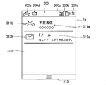
- FIG. 7 is a diagram illustrating an example of the notification image 310.
- the notification image 310 is displayed so as to gradually extend downward in response to a downward sliding operation on the display area 2a (pull-down display).
- the notification image 310 is displayed in an area other than the notification area 300 in the display area 2a.
- the notification image 310 includes a character string 311 a and an icon 311 b for notifying the occurrence of a missed call, corresponding to the icon 300 e displayed in the notification area 300.
- the notification image 310 includes a character string 312a and an icon 312b for notifying the occurrence of reception of a new email corresponding to the icon 300d displayed in the notification area 300.
- the notification image 310 includes a non-display operation start point region 313 that is a start point of an operation for hiding the notification image 310.
- the touch panel 130 detects an upward sliding operation by the operator 60 with respect to the display area 2a starting from the non-display operation start point area 313, the display panel 120 deletes the display of the notification image 310 in the display area 2a.
- each of the left end 320 and the right end 321 of the display area 2 a becomes the start point of an operation for setting the operation mode of the electronic device 1 to the selection mode. ing.
- “left side” means the left side when viewing the display area 2a
- “right side” means the right side when viewing the display area 2a.
- the operation element 60 moves from the right end 321 of the display area 2a in the selection mode setting direction 330 by a predetermined distance (for example, 1 cm) or more.
- the control unit 100 sets the operation mode of the electronic device 1 to the selection mode. That is, when the operation mode of the electronic device 1 is the normal mode, the touch panel 130 indicates that the operation element 60 has been slid by a predetermined distance or more in the selection mode setting direction 330 starting from the right end 321 with respect to the display area 2a. Is detected, the control unit 100 sets the operation mode of the electronic device 1 to the selection mode.
- the operating element 60 before movement is indicated by a wavy line. The same applies to the following figures.
- the selection mode setting direction 330 is a direction inward from the right end 321 when the movement of the operation element 60 starts from the right end 321 of the display area 2a as in this example. Specifically, when the movement of the operation element 60 starts from the right end 321 of the display area 2a, the selection mode setting direction 330 is the left-right direction (vertical direction) that goes inward from the right end 321 of the display area 2a. Direction perpendicular to the direction).
- the mode setting direction 330 is a direction along the left-right direction that goes inward from the left end 320 of the display area 2a. Therefore, when the operation mode of the electronic device 1 is the normal mode, when the user holds the electronic device 1 in the left hand and moves the thumb of the left hand inward from the left end 320 of the display area 2a along the left-right direction.
- the operation mode of the electronic device 1 is the selection mode.
- the control unit 100 stores operation mode information indicating the current operation mode. When the operation mode of the electronic device 1 is changed, the control unit 100 updates the operation mode information accordingly.
- the operation by the operation element 60 for the display area 2a for setting the operation mode of the electronic device 1 to the selection mode is referred to as “selection mode setting operation”.
- the selection mode setting operation is an operation in which the operation element 60 moves from the right end 321 or the left end 320 of the display area 2a in the selection mode setting direction 330 by a predetermined distance or more as described above.
- FIG. 9 is a diagram showing a display in the display area 2a when the operation mode of the electronic device 1 is set to the selection mode.
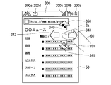
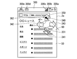
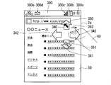
- a first arrow 340 pointing upward and a second arrow 341 pointing downward are displayed on the upper and lower sides of the adjacent parts so as not to overlap the operation element 60.
- a cursor 350 is displayed on the first arrow 340 so as not to overlap the operation element 60.
- a magnifying glass figure 351 indicating an enlarged border so as not to overlap with the operation element 60 is displayed superimposed on the second arrow 341.
- the display panel 120 displays the first arrow 340, the second arrow 341, the cursor 350, and the magnifying glass figure 351 in addition to the portion of the display area 2a where the operation element 60 is in contact with or close to the display area 2a. It is displayed in the display area 2a so as not to overlap the child 60.
- the cursor 350 is displayed in the display area 2a so as not to overlap with the operation element 60 that is in contact with or close to the display area 2a. Therefore, it is possible to prevent the cursor 350 from being hidden behind the operator 60 and not knowing where it exists.
- the operation area 60 After the selection mode setting operation is performed on the display area 2a, that is, after the operation element 60 moves the right end 321 or the left end 320 of the display area 2a in the selection mode setting direction 330, the operation area 60 enters the display area 2a.
- the control unit 100 cancels the selection mode and sets the operation mode of the electronic device 1 to the normal mode. .
- the user can easily cancel the selection mode simply by releasing the operation element 60 from the display area 2a.
- the control unit 100 cancels the selection mode, and the electronic device 1 operation mode is set to the normal mode.
- the user can easily cancel the selection mode only by moving the operation element 60 in the selection mode canceling direction 331 in the display area 2a.
- the display of the first arrow 340, the second arrow 341, the cursor 350, and the magnifier graphic 351 is deleted.
- the operating element 60 When the electronic device 1 is in the selection mode, as shown in FIG. 11, the operating element 60 has moved in the same direction as the direction indicated by the first arrow 340 (upward) in the display area 2a by a predetermined distance or more. Is detected by the touch panel 130, the control unit 100 sets the operation mode of the electronic device 1 to the cursor display mode.
- the moving direction of the operation element 60 for setting the cursor display mode is referred to as “cursor display mode setting direction 360”.
- the cursor display mode setting direction 360 is the same direction as the direction indicated by the first arrow 340, that is, the upward direction.
- the display panel 120 sets the cursor 350 in the display area 2a in accordance with the movement of the operation element 60 under the control of the control unit 100. Move in direction 360. Specifically, the display panel 120 moves the cursor 350 in the cursor display mode setting direction 360 in the display area 2a, which is larger than the movement amount of the operation element 60. Thereby, even if the operation element 60 moves in the cursor display mode setting direction 360, it is possible to suppress the cursor 350 from overlapping the operation element 60 as shown in FIG.
- the cursor display mode setting operation is an operation in which the operation element 60 moves in the cursor display mode setting direction 360 by a predetermined distance or more as described above.
- control unit 100 sets the operation mode of electronic device 1 to the enlargement / reduction mode.
- the moving direction of the operation element 60 for setting the enlargement / reduction mode is referred to as “enlargement / reduction mode setting direction 361”.
- the enlargement / reduction mode setting direction 361 is the same as the direction indicated by the second arrow 341, that is, the downward direction.
- an operation performed by the operator 60 on the display area 2a for setting the electronic apparatus 1 to the enlargement / reduction mode is referred to as an “enlargement / reduction mode setting operation”.
- the enlargement / reduction mode setting operation is an operation in which the operation element 60 moves in the enlargement / reduction mode setting direction 361 by a predetermined distance or more.
- the first arrow 340 pointing in the same direction as the cursor display mode setting direction 360 for setting the operation mode of the electronic device 1 to the cursor display mode is displayed in the display area 2a.
- the user can easily set the operation mode of the electronic device 1 to the cursor display mode with reference to the display in the display area 2a.
- the second arrow 341 directed in the same direction as the enlargement / reduction mode setting direction 361 for setting the operation mode of the electronic device 1 to the enlargement / reduction mode is displayed in the display area 2a, the user can display the display area 2a. This makes it easy to set the operation mode of the electronic device 1 to the enlargement / reduction mode.
- the selection mode is canceled when the operator 60 that is in contact with or close to the display area 2a leaves the display area 2a. Therefore, in order to set the operation mode of the electronic device 1 to the cursor display mode, after the selection mode setting operation is performed on the display area 2a, the operator 60 does not leave the display area 2a, and the cursor display mode is set. It is necessary to move in the setting direction 360.
- the operation element 60 is enlarged without leaving the display area 2a. It is necessary to move in the reduction mode setting direction 361.
- FIG. 13 is a diagram showing this state.
- the cursor 350 before movement is indicated by a white arrow. The same applies to the following figures.
- the display panel 120 moves the cursor 350 in the same direction as the movement direction of the movement of the operation element 60 in the display area 2a detected by the touch panel 130.
- the display panel 120 moves the cursor 350 larger than the movement amount with respect to the movement of the operation element 60 in the display area 2 a detected by the touch panel 130.
- the display panel 120 moves the cursor 350 three times or more than the movement amount detected by the touch panel 130 for the movement of the operation element 60 in the display area 2a.
- the user can move the operation element 60 in the display area 2a and move the cursor 350 in the display area 2a so as to move the mouse cursor in the display by moving the mouse in the personal computer.
- the operator 60 moves in the display area 2a, so that the operator 60 moves away from the display area 2a after the tip of the cursor 350 has moved over the display target in the display area 2a.
- the electronic device 1 executes a process associated with the display target indicated by the cursor 350 in the display area 2a.
- the user can use the cursor 350 to select a display target of the display area 2a and cause the electronic device 1 to execute processing associated with the display target.
- an operation in which the operation element 60 moves away from the display area 2a corresponds to a tap operation in the normal mode.
- the cursor 350 moves so that the tip of the cursor 350 is positioned on the link (display target) in the web page 50 as shown in FIG.
- the touch panel 130 detects that the operator 60 has moved away from the display area 2a
- the link indicated by the cursor 350 is selected, and the electronic device 1 executes the process associated with the link. That is, the electronic device 1 acquires the web page indicated by the selected link from the web server and displays it on the display area 2a.
- the display panel 120 changes the display color of the link so that the user can understand it.
- the link may be focused by, for example, changing the display color around the link.
- the control unit 100 reads the application 103b corresponding to the selected application icon 370 from the storage unit 103 and executes it.
- the control unit 100 functions as a process execution unit that executes a process associated with a display target in the display area 2a.
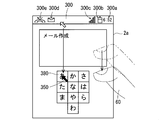
- the control unit 100 includes a character associated with the selected character input button 380 in the e-mail being created, and the display panel 120 displays the character in the display area 2a.
- the control unit 100 and the display panel 120 function as a process execution unit that executes a process associated with a display target in the display area 2a.
- the cursor 350 for executing the process associated with the display target such as the link and the application icon displayed in the display area 2a is the amount of movement of the operation element 60. Move bigger than. Therefore, the user holds the electronic device 1 with one hand (see FIGS. 4 and 5), and it is difficult for the thumb (operator) of one hand to operate the end of the display area 2a.
- the cursor 350 can be moved to the end of the display area 2a by moving the thumb a little. Thereby, even if it is difficult for the thumb of one hand holding the electronic device 1 to operate the end of the display area 2a, the user is associated with the display target displayed at the end of the display area 2a. Can be executed by the electronic device 1. Therefore, even when the user operates the electronic device 1 with one hand, the user can easily operate the electronic device 1. As a result, the operability of the electronic device 1 is improved.
- touch panel 130 indicates that operator 60 has moved away from display area 2a after moving in display area 2a so that cursor 350 points to a display target such as a link in display area 2a. Is detected, the process associated with the display target indicated by the cursor 350 is executed. Therefore, after the user moves the operation element 60 to move the cursor 350 to the display target, the user simply moves the operation element 60 away from the display area 2a, and performs processing associated with the display object indicated by the cursor 350 on the electronic device 1. Can be executed. Therefore, the operation of the electronic device 1 by the user becomes very simple. That is, the operability of the electronic device 1 is improved.
- the relationship between the movement amount of the operation element 60 and the movement amount of the cursor may be changed by the user operating the display area 2 a with the operation element 60.
- ⁇ Release cursor display mode> In the present embodiment, in the cursor display mode, when it is detected by touch panel 130 that operator 60 has moved away from display area 2a, control unit 100 cancels the cursor operation mode and changes the operation mode of electronic device 1. Set to normal mode. Thereby, the user can cancel
- operation element 60 leaves display area 2a while cursor 350 points to a display target such as a link processing associated with the display target is executed and cursor display is performed. The mode is released.
- control unit 100 detects, on the touch panel 130, a flick operation by the operator 60 on the display area 2a instead of or in addition to releasing the cursor operation mode when the operator 60 leaves the display area 2a. Then, the cursor operation mode may be canceled and the operation mode of the electronic device 1 may be set to the normal mode. As a result, the user can easily cancel the cursor display mode simply by performing a flick operation on the display area 2a with the operation element 60.
- the control unit 100 may release the cursor display mode when a flick operation in a predetermined direction is detected on the touch panel 130, and when the flick operation is detected on the touch panel 130, the control unit 100 sets the cursor display mode regardless of the direction. You may cancel.
- control unit 100 may set a predetermined direction of the flick operation for canceling the cursor display mode as one direction (for example, upward direction) or a plurality of directions (for example, upward direction, downward direction, right direction, and left direction). It is also good.
- the display panel 120 displays An enlarged image (enlarged screen) 390 showing an enlarged area around the cursor 350 in the area 2a is displayed.
- the enlarged image 390 is displayed so as to overlap the display screen currently displayed in the display area 2a.
- FIG. 16 is a diagram showing a state where the enlarged image 390 is displayed in the display area 2a.
- the user can use the cursor 350 to display a display target such as a link that is largely shown in the enlarged image 390.
- a display target such as a link that is largely shown in the enlarged image 390.
- the display panel 120 displays the enlarged image 390 with the brightness of the display screen so that the original display screen in the background of the enlarged image 390 is viewed darker than the enlarged image 390 in the display area 2a. It may be lower than before.
- the display panel 120 displays the enlarged image 390. Clear the display.
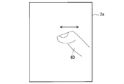
- the display panel 120 when the touch panel 130 detects that the operation element 60 has reciprocated within a predetermined time while being in contact with or close to the display area 2a, the display panel 120 The display in the display area 2a is enlarged at a predetermined magnification. Specifically, the operator 60 contacts and moves in a certain direction for a predetermined distance within a predetermined time while in contact with or close to the display area 2a, and then contacts for a predetermined distance in a direction opposite to the certain direction. When the touch panel 130 detects that it has moved, the display panel 120 enlarges the display of the display area 2a.
- the touch panel 130 detects again that the operation element 60 has reciprocated within a predetermined time while being in contact with or close to the display area 2a.
- the display panel 120 reduces the display size of the display area 2a to restore the display size.
- the display panel 120 may enlarge and reduce the display of the display area 2a based on the center of the display area 2a when the display of the display area 2a is enlarged and reduced. Further, the display panel 120 enlarges and reduces the display of the display area 2a based on the initial position (position when the reciprocation starts) when the operation element 60 reciprocates within a predetermined time. You may do it. Further, the display panel 120 enlarges and reduces the display of the display area 2a based on the last position (position when the reciprocation is completed) of the operation element 60 when the operation element 60 reciprocates within a predetermined time. You may do it.
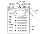
- ⁇ Display notification image in cursor display mode> in the cursor display mode, as shown in FIG. 19, the operation element 60 moves in the display area 2 a to move the cursor 350 to the notification area 300, and then the operation element 60 moves to the display area 2 a.
- the touch panel 130 detects that the user has left the display area
- the display panel 120 displays the notification image 310 in an area other than the notification area 300 in the display area 2a as illustrated in FIG. 7 described above.
- the user can easily display the notification image 310 on the electronic device 1 simply by moving the operation element 60 away from the display area 2a while the cursor 350 is positioned in the notification area 300.
- the cursor 350 moves to the notification area 300 of the display area 2a, and then moves the cursor 350 from the notification area 300 to the outside of the display area 2a.
- the display panel 120 may display the notification image 310 in an area other than the notification area 300 in the display area 2a. That is, when the touch panel 130 detects the movement of the operation element 60 that causes the cursor 350 to pass through the notification area 300 of the display area 2a and move from the upper end of the display area 2a to the outside of the display area 2a, the display panel 120 notifies The image 310 may be displayed. Accordingly, the user can easily display the notification image 310 on the electronic device 1 simply by moving the operation element 60 in the display area 2a.
- the display panel 120 may display the notification image 310 in an area other than the notification area 300 in the display area 2a.
- the control unit 100 may cancel the cursor operation mode and set the operation mode of the electronic device 1 to the normal mode.
- the operation mode of the electronic device 1 is set to the enlargement / reduction mode.
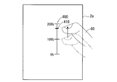
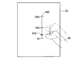
- the display panel 120 displays a zoom control bar 400 (also referred to as “zoom slider”) for controlling the display magnification in the display area 2a.
- the zoom control bar 400 shows a setting bar 410 that indicates the currently set display magnification.
- the display panel 120 is configured so that the operation element 60 touches or is displayed in the display area 2a so that the zoom control bar 400 is displayed in the vicinity of the operation element 60 without overlapping the operation element 60 in contact with the display area 2a.
- the zoom control bar 400 is displayed near the adjacent part.
- the zoom control bar 400 is displayed such that the setting bar 410 is positioned beside the portion where the operating element 60 is in contact with or close to the display area 2a.
- the display of the display area 2a is enlarged and reduced with the center of the display area 2a as a base point.
- the display panel 120 when it is detected by the touch panel 130 that the operation element 60 has moved upward in the display area 2a, that is, when an upward slide operation is detected by the touch panel 130, the display panel 120 is displayed.
- the display area 2a is enlarged under the control of the control unit 100.
- the display panel 120 changes the display magnification according to the movement distance of the operation element 60.
- the display panel 120 changes the position of the setting bar 410 on the zoom control bar 400 according to the display magnification after the change.
- an operation performed by the operator 60 on the display area 2a for enlarging the display of the display area 2a is referred to as an “enlargement execution operation”.
- the enlargement execution operation is an operation in which the operator 60 moves upward in the display area 2a.
- the display The panel 120 reduces the display of the display area 2 a under the control of the control unit 100. At this time, the display panel 120 changes the display magnification according to the movement distance of the operation element 60. Further, the display panel 120 changes the position of the setting bar 410 on the zoom control bar 400 according to the display magnification after the change.
- a reduction execution operation an operation by the operator 60 for reducing the display in the display area 2a is referred to as a “reduction execution operation”.
- the reduction execution operation is an operation in which the operator 60 moves downward in the display area 2a.
- the control unit 100 cancels the enlargement / reduction mode and changes the operation mode of the electronic device 1.
- the display magnification in the display area 2a when the enlargement / reduction mode is canceled is preferably the display magnification set last in the enlargement / reduction mode.
- an up arrow 415 and a down arrow 417 may be displayed in the display area 2a instead of the zoom control bar 400.
- the up arrow 415 and the down arrow 417 are respectively displayed on the upper side and the lower side of the portion where the operating element 60 is in contact with or close to the display area 2a.
- a graphic 416 indicating the enlargement process is displayed superimposed on the up arrow 415
- a graphic 418 indicating the reduction process is displayed superimposed on the down arrow 417. It is desirable that the up arrow 415, the down arrow 417, and the graphics 416 and 418 are displayed so as not to overlap the operation element 60.
- the display of the display area 2a is enlarged or reduced in accordance with the movement of the operation element 60 in the display area 2a in the same manner as described above. That is, when the touch panel 130 detects that the operation element 60 has moved upward in the display area 2a, the display panel 120 enlarges the display of the display area 2a with a magnification corresponding to the movement amount of the operation element 60.
- the display mode of the up arrow 415 may be changed. For example, the size of the up arrow 415 may increase, or the display color of the up arrow 415 may change.
- the display panel 120 reduces the display of the display area 2 a at a magnification corresponding to the movement amount of the operation element 60.
- the display mode of the down arrow 417 may be changed. For example, the size of the down arrow 417 may increase, or the display color of the down arrow 417 may change.
- the display in the display area 2a is enlarged or reduced according to the moving direction.
- the display of the display area 2a can be enlarged or reduced by a simple operation on the electronic device 1.
- the selection mode setting operation is merely examples, and other operations by the operator 60 for the display area 2a may be adopted as these operations. good.
- the selection mode setting operation may be an operation in which the tap operation is continuously performed three times or more on the display area 2a within a predetermined time.
- the selection mode setting direction 330, the cursor display mode setting direction 360, and the enlargement / reduction mode setting direction 361 according to the present embodiment are also examples, and other directions may be adopted as these directions.
- the cursor display mode setting direction 360 and the enlargement / reduction mode setting direction 361 may be the upper left direction and the upper right direction, respectively.
- the operation by the operation element 60 for the display area 2a for releasing the selection mode, the cursor display mode, and the enlargement / reduction mode is also an example. As these operations, other operations by the operation element 60 for the display area 2a are performed. An operation may be employed.
- the movement direction of the operation element 60 in the enlargement execution operation and the reduction execution operation in the enlargement / reduction mode according to the present embodiment is also an example, and other directions may be adopted as these movement directions. good.
- the enlargement execution operation and the reduction execution operation in the enlargement / reduction mode described above are examples, and other operations by the operator 60 for the display area 2a may be adopted as these operations.
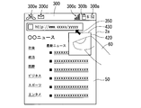
- the control unit 100 includes a reception area 420 in which movement of the operation element 60 for moving the cursor 350 in the display area 2a is accepted when the operation mode of the electronic device 1 is set to the cursor display mode.
- Set for display area 2a The display panel 120 moves the cursor 350 only when the operator 60 moves in the reception area 420. Accordingly, the reception area 420 functions as a mouse pad on which a mouse used in a personal computer or the like is moved.
- FIG. 26 is a diagram showing a state in which the reception area 420 is set for the display area 2a.
- the control unit 100 makes contact with the operation element 60 in the display area 2a at the time when the movement of the operation element 60 in the cursor display mode setting operation ends.
- the reception area 420 is set in the display area 2a so as to include a close part.
- the display panel 120 moves the cursor 350 as described above only when the operator 60 moves in the reception area 420.
- control unit 100 does not cancel the cursor display mode when the touch panel 130 detects that the operation element 60 is separated from the display area 2 a, but the operation element 60 does not cancel the cursor display mode.
- the touch panel 130 detects that it has not been operated for a predetermined time or longer (for example, 2 seconds or longer)
- the cursor display mode is canceled.
- the electronic apparatus 1 handles the operation by the operator 60 for the area other than the reception area 420 in the display area 2a in the same manner as the operation by the operator 60 for the display area 2a in the normal mode. For example, in a region other than the reception region 420 in the display region 2a, when a tap operation is performed on a portion where a link in the web page is displayed, the electronic device 1 displays the web page indicated by the link in the web server. And is displayed in the display area 2a. In addition, when a slide operation along the vertical direction is performed on an area other than the reception area 420 in the display area 2a, the display in the display area 2a is scrolled.
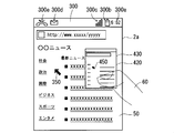
- FIG. 27 is a diagram illustrating a state where the display area 120 displays a reception area image 430 indicating the reception area 420 on the display area 2a so that the range of the reception area 420 can be specified.
- the reception area image 430 is displayed so as to be superimposed on the display screen (display screen before the reception area image 430 is displayed) originally displayed on the display area 2a.
- the size of the reception area image 430 is the same as the size of the reception area 420, and the display position of the reception area image 430 in the display area 2a is the same as the position of the reception area 420 in the display area 2a.
- the reception area image 430 may be any image as long as the position and range of the reception area 420 in the display area 2a are known.
- a transparent image may be displayed as the reception area image 430 so that the background (lower) image can be seen.
- a transparent image with high luminance may be displayed as the reception area image 430 so that the reception area image 430 appears to shine.
- An image showing only a frame having the same size as the reception area 420 may be displayed as the reception area image 430.
- a part of the display screen originally displayed in the display area 2a is displayed inside the frame indicated by the reception area image 430.
- a reduced screen obtained by reducing the display screen including the cursor 350 displayed in the display area 2a may be displayed as the reception area image 430.
- FIG. 28 is a diagram showing this state.
- a reduced screen obtained by reducing the display screen displayed in the display area 2a is displayed as the reception area image 430
- a reduced version 450 of the cursor 350 is shown in the reception area image 430.
- the reduced version 450 of the cursor 350 moves in the reception area image 430 when the cursor 350 moves in the display area 2a. Therefore, the user can specify the position of the cursor 350 in the display area 2 a by viewing the reduced version 450 of the cursor 350 in the reception area image 430. Therefore, the user can specify the position of the cursor 350 in the display area 2a by looking at the vicinity of the operation element 60 moving on the reception area 420. Therefore, operation with respect to the electronic device 1 becomes easy.
- reception area image 430 may be displayed while the electronic device 1 operates in the cursor display mode, or may be temporarily displayed. That is, in the cursor display mode, the electronic device may always notify the user of the position and range of the reception area 420 set in the display area 2a, or may notify only temporarily.
- the reception area image 430 When the reception area image 430 is temporarily displayed in the display area 2a, the reception area image 430 may be displayed for a certain period from the time when the operation mode of the electronic device 1 is set to the cursor display mode. good. Alternatively, the reception area image 430 may be displayed for a predetermined time from when the operation element 60 starts operating the reception area 420 again after the operation area 60 no longer operates the reception area 420.
- the electronic device 1 may not include the enlargement / reduction mode as the operation mode.
- the selection mode is not necessary.
- the same operation as the selection mode setting operation described above may be adopted as the cursor display mode setting operation.
- control unit 100 sets the operation mode of electronic device 1 to the cursor display mode.
- the operation mode of the electronic device s100 is the normal mode
- the touch panel 130 detects that the operation element 60 has moved inward from the left end 320 of the display area 2a by a predetermined distance or more
- the control unit 100 Sets the operation mode of the electronic device 1 to the cursor display mode.
- the operation element 60 is in contact with or close to the display area 2a after moving inward from the right end 321 or the left end 320 of the display area 2a.
- the control unit 100 cancels the cursor display mode.
- the electronic device 1 may include a mode other than the cursor display mode and the enlargement / reduction mode as a type of mode selected when the electronic device 1 operates in the selection mode.
- the electronic device 1 may include a display mode in which a display target associated with a process (function) such as an application icon is displayed.
- a display target associated with a process such as an application icon is displayed.
- the display mode is referred to as a second display mode in order to distinguish it from the cursor display mode.
- the electronic apparatus 1 displays a first icon display mode in which an application icon for executing the recently executed application 103b is displayed as a second display mode, and an application icon selected by the user. And a second icon display mode.
- the operation mode of the electronic device 1 is the selection mode, one of the cursor display mode, the enlargement / reduction mode, the first icon display mode, and the second icon display mode is selected by the user.
- each is simply referred to as “icon display mode”.
- the state in which the electronic device 1 is not operating in the cursor display mode, the enlargement / reduction mode, the first icon display mode, the second icon display mode, and the selection mode is the normal mode.
- the display area In 2a in addition to the first arrow 340 and the second arrow 341, the third arrow 342 pointing left and the fourth arrow 343 pointing right are located on the left and right sides of the portion where the operating element 60 is in contact with or in close proximity. Is displayed.
- the control unit 100 sets the operation mode of the electronic device 1 to the first icon display mode.
- an operation performed by the operator 60 on the display area 2a for setting the electronic device 1 to the first icon display mode is referred to as a “first icon display mode setting operation”.
- the “first icon display mode setting operation” is an operation in which the operator 60 moves in the first icon display mode setting direction 362 as described above.
- control unit 100 sets the operation mode of electronic device 1 to the second icon display mode.
- the “second icon display mode setting operation” is an operation in which the operator 60 moves in the second icon display mode setting direction 363.
- the touch panel 130 detects that the operation element 60 that is in contact with or close to the display area 2a is separated from the display area 2a. Then, the control unit 100 cancels the selection mode.
- the operating element 60 moves in the selection mode setting direction 330 from the right end 321 or the left end 320 of the display area 2a
- the operating element 60 that is in contact with or close to the display area 2a is shown in FIG.
- the control unit 100 cancels the selection mode.
- the control unit 100 determines whether to cancel the selection mode or set the operation mode of the electronic device 1 to the second icon display mode according to the moving distance of the operation element 60.
- the operation element 60 moves from the right end 321 or the left end 320 of the display area 2a in the selection mode setting direction 330, the operation element 60 does not leave the display area 2a and cancels the selection mode.
- the touch panel 130 detects that the user has moved in the direction 331 (second icon display mode setting direction 363) by a predetermined distance or more, the control unit 100 cancels the selection mode.
- control unit 100 sets the operation mode of the electronic device 1 to the second icon display mode. That is, after the operating element 60 has moved in contact with the selection mode setting direction 330 from the right end 321 or the left end 320 of the display area 2a, the operating element 60 does not leave the display area 2a, and the second icon display mode.
- control unit 100 sets the operation mode of electronic device 1 to the second icon display mode.
- FIG. 32 is a diagram showing a display example of the application icon 370 in the icon display mode.
- the icon display mode for example, a plurality of application icons 370 are displayed at the center of the display area 2a.
- the application icon 370 for executing the recently executed application 103b is displayed, and in the second icon display mode, the application icon 370 selected by the user is displayed.
- the operation mode of the electronic device 1 is the normal mode, the user can determine the application icon 370 displayed in the second icon display mode by operating the display area 2a with the operation element 60.
- an operation in which the operator 60 leaves the display area 2a on the display of the application icon 370 in the display area 2a is an operation for selecting the application icon 370. That is, when the operation mode of the electronic device 1 is the icon display mode, the operation element 60 moves so as to be positioned on the display of the application icon 370 in the display area 2a, and then the operation element 60 is displayed at the position.
- the touch panel 130 detects that the user has left the area 2a, the application icon 370 is selected, and the control unit 100 reads out and executes the application 103b corresponding to the selected application icon 370 from the storage unit 103.
- control unit 100 cancels the icon display mode and sets the operation mode of electronic device 1 to the normal mode.
- the application icon 370 is displayed in the center of the display area 2a, so that the user can easily select the application icon 370 with the right thumb and the left thumb. Therefore, the user can easily operate the electronic device 1 with one hand.
- the cursor display mode setting direction 360, the enlargement / reduction mode setting direction 361, the first icon display mode setting direction 362, and the second icon display mode setting direction 363 are respectively upward, downward, and leftward. Although it is set as the right direction, it may be set in another direction.
- the cursor display mode setting direction 360, the enlargement / reduction mode setting direction 361, the first icon display mode setting direction 362, and the second icon display mode setting direction 363 may be set to the right direction, the left direction, the upward direction, and the downward direction, respectively. good.
- the operation mode of the electronic device 1 becomes the selection mode, and then the operation mode of the electronic device 1 is set to the icon display mode.
- the display panel 120 may display an application icon 370 in the right half area of the display area 2a. Accordingly, when the user holds the electronic device 1 with the right hand, the application icon 370 can be easily selected with the thumb of the right hand.
- the operation unit 60 moves from the left end 320 of the display area 2a in the selection mode setting direction 330 so that the operation mode of the electronic device 1 becomes the selection mode, and then the operation mode of the electronic device 1 changes to the icon display mode.
- the display panel 120 may display the application icon 370 in the left half area of the display area 2a. Thereby, when the user holds the electronic device 1 with the left hand, the application icon 370 can be easily selected with the thumb of the left hand.
- the electronic device 1 has the first and second icon display modes as the second display mode, but has only one of the first and second icon display modes. May be.
- a display target other than the application icon may be displayed together with the application icon, or a display target other than the application icon. Only may be displayed.
- the second display mode when a display target other than the application icon is displayed, for example, a brightness change button represented by a graphic or the like for changing the brightness of the display area 2a is displayed on the display area 2a. good.
- a display target other than the application icon for example, a brightness change button represented by a graphic or the like for changing the brightness of the display area 2a is displayed on the display area 2a.
- the touch panel 130 detects that the operator 60 is separated from the display area 2a on the display of the brightness change button in the display area 2a, the brightness change button is selected.
- the control part 100 changes the brightness
- wireless LAN function Local Area Network
- a wireless LAN setting button represented by a figure or the like for turning on / off the wireless LAN function in the electronic device 1 may be displayed in the display area 2a.
- the wireless LAN setting button is selected.
- the control unit 100 turns on when the wireless LAN function is currently turned off, and turns on when the wireless LAN function is currently turned on. Turn off.
Landscapes
- Engineering & Computer Science (AREA)
- General Engineering & Computer Science (AREA)
- Theoretical Computer Science (AREA)
- Human Computer Interaction (AREA)
- Physics & Mathematics (AREA)
- General Physics & Mathematics (AREA)
- User Interface Of Digital Computer (AREA)
- Position Input By Displaying (AREA)
Abstract
電子機器の動作モードを決定する決定部は、表示領域に対する操作子による第1操作を検出部が検出した場合に、動作モードを、表示領域にカーソルが表示されるカーソル表示モードに決定する。表示部は、動作モードがカーソル表示モードである場合に、検出部が検出する表示領域での操作子の移動に応じて、表示領域においてカーソルを移動する。処理実行部は、動作モードがカーソル表示モードである場合に、表示領域においてカーソルが表示対象を指し示すように操作子が表示領域において移動した後に表示領域から離れたことを検出部が検出した際には、当該カーソルが指し示す表示対象に関連付けられた処理を実行する。
Description
本発明は、電子機器に関する。
従来から電子機器に関して様々な技術が提案されている。
さて、電子機器については、その操作性の向上が望まれている。
そこで、本発明は上述の点に鑑みて成されたものであり、電子機器の操作性を向上することを可能にする技術を提供することを目的とする。
ある態様に係る電子機器は、前記電子機器の動作モードを決定する決定部と、表示領域に表示を行う表示部と、前記表示領域に対する操作子による操作を検出する検出部と、前記表示領域に表示されている表示対象に関連付けられた処理を実行する処理実行部とを備え、前記決定部は、前記表示領域に対する前記操作子による第1操作を前記検出部が検出した場合に、前記動作モードを、前記表示領域にカーソルが表示されるカーソル表示モードに決定し、前記表示部は、前記動作モードが前記カーソル表示モードである場合に、前記検出部が検出する前記表示領域での前記操作子の移動に応じて、前記表示領域においてカーソルを移動し、前記処理実行部は、前記動作モードが前記カーソル表示モードである場合に、前記表示領域においてカーソルが表示対象を指し示すように前記操作子が前記表示領域において移動した後に前記表示領域から離れたことを前記検出部が検出した際には、当該カーソルが指し示す表示対象に関連付けられた処理を実行する。
また、ある態様に係る制御プログラムは、表示領域を有する電子機器を制御するための制御プログラムであって、前記電子機器に、(a)前記表示領域に対する操作子の第1操作を検出した場合に、前記電子機器の動作モードを、前記表示領域にカーソルが表示されるカーソル表示モードに決定する工程と、(b)前記動作モードが前記カーソル表示モードである場合に、前記検出部が検出する前記表示領域での前記操作子の移動に応じて、前記表示領域においてカーソルを移動する工程と、(c)前記動作モードが前記カーソル表示モードである場合に、前記表示領域においてカーソルが表示対象を指し示すように前記操作子が前記表示領域において移動した後に前記表示領域から離れたことを検出した際には、当該カーソルが指し示す表示対象に関連付けられた処理を実行する工程とを実行させるためのものである。
また、ある態様に係る電子機器の動作方法は、表示領域を有する電子機器の動作方法であって、(a)前記表示領域に対する操作子の第1操作を検出した場合に、前記電子機器の動作モードを、前記表示領域にカーソルが表示されるカーソル表示モードに決定する工程と、(b)前記動作モードが前記カーソル表示モードである場合に、前記検出部が検出する前記表示領域での前記操作子の移動に応じて、前記表示領域においてカーソルを移動する工程と、(c)前記動作モードが前記カーソル表示モードである場合に、前記表示領域においてカーソルが表示対象を指し示すように前記操作子が前記表示領域において移動した後に前記表示領域から離れたことを検出した際には、当該カーソルが指し示す表示対象に関連付けられた処理を実行する工程とを備える。
本発明の一態様によれば、電子機器の操作性が向上する。
この発明の目的、特徴、局面、及び利点は、以下の詳細な説明と添付図面とによって、より明白となる。
<電子機器の外観>
図1,2は、それぞれ、実施の形態に係る電子機器1の外観を示す前面図及び裏面図である。本実施の形態に係る電子機器1は、例えば携帯電話機である。電子機器1は、基地局及びサーバ等を通じて他の通信装置と通信することが可能である。図1及び2に示されるように、電子機器1は、カバーパネル2とケース部分3を備えている。カバーパネル2とケース部分3とが組み合わされることによって、平面視で略長方形の板状を成す機器ケース4が構成される。
図1,2は、それぞれ、実施の形態に係る電子機器1の外観を示す前面図及び裏面図である。本実施の形態に係る電子機器1は、例えば携帯電話機である。電子機器1は、基地局及びサーバ等を通じて他の通信装置と通信することが可能である。図1及び2に示されるように、電子機器1は、カバーパネル2とケース部分3を備えている。カバーパネル2とケース部分3とが組み合わされることによって、平面視で略長方形の板状を成す機器ケース4が構成される。
カバーパネル2は、平面視において略長方形を成している。カバーパネル2は、電子機器1の前面部分における、周縁部分以外の部分を構成している。カバーパネル2は、例えば、透明のガラスあるいは透明のアクリル樹脂で形成されている。ケース部分3は、電子機器1の前面部分の周縁部分、側面部分及び裏面部分を構成している。ケース部分3は、例えばポリカーボネート樹脂で形成されている。
カバーパネル2の前面には、文字、記号、図形等の各種情報が表示される表示領域2aが設けられている。表示領域2aは例えば平面視で長方形を成している。カバーパネル2における、表示領域2aを取り囲む周縁部分2bは、例えばフィルム等が貼られることによって黒色となっている。これにより、当該周縁部分2bは、情報が表示されない非表示部分となっている。カバーパネル2の裏面には後述するタッチパネル130が貼り付けられている。ユーザは、電子機器1の前面の表示領域2aを指等で操作することによって、電子機器1に対して各種指示を与えることができる。なお、ユーザは、指以外の操作子、例えば、スタイラスペンなどの静電式タッチパネル用ペンで表示領域2aを操作することによっても、電子機器1に対して各種指示を与えることができる。
機器ケース4内には、ホームキー5a、メニューキー5b及びバックキー5cが設けられている。ホームキー5a、メニューキー5b及びバックキー5cのそれぞれは、ハードウェアキーである。ホームキー5a、メニューキー5b及びバックキー5cのそれぞれの表面は、カバーパネル2の前面の下側端部から露出している。ホームキー5aは、表示領域2aに、ホーム画面(初期画面)を表示するための操作キーである。メニューキー5bは、オプションメニュー画面を表示するための操作キーである。バックキー5cは、表示領域2aの表示を一つ前の表示に戻すための操作キーである。以後、ホームキー5a、メニューキー5b及びバックキー5cを特に区別する必要が無い場合には、それぞれを「操作キー5」と呼ぶ。なお、ホームキー5a、メニューキー5b及びバックキー5cのそれぞれは、ハードウェアキーではなく、表示領域2aに表示されて、タッチパネル130でそれに対する操作が検出されるソフトウェアキーであってもよい。
カバーパネル2の下側端部にはマイク穴6があけられている。カバーパネル2の上側端部にはレシーバ穴7があけられている。カバーパネル2の前面の上側端部からは、後述する前面側撮像部180が有する撮像レンズ180aが視認可能となっている。また、図2に示されるように、電子機器1の裏面、言い換えれば機器ケース4の裏面には、スピーカ穴8があけられている。そして、電子機器1の裏面からは、後述する裏面側撮像部190が有する撮像レンズ190aが視認可能となっている。
<電子機器の電気的構成>
図3は電子機器1の電気的構成を示すブロック図である。図3に示されるように、電子機器1には、制御部100、無線通信部110、表示パネル120、タッチパネル130及びキー操作検出部140が設けられている。さらに電子機器1には、マイク150、レシーバ160、外部スピーカ170、前面側撮像部180、裏面側撮像部190及び電池200が設けられている。電子機器1に設けられたこれらの構成要素は、機器ケース4内に収められている。
図3は電子機器1の電気的構成を示すブロック図である。図3に示されるように、電子機器1には、制御部100、無線通信部110、表示パネル120、タッチパネル130及びキー操作検出部140が設けられている。さらに電子機器1には、マイク150、レシーバ160、外部スピーカ170、前面側撮像部180、裏面側撮像部190及び電池200が設けられている。電子機器1に設けられたこれらの構成要素は、機器ケース4内に収められている。
制御部100は、CPU(Central Processing Unit)101、DSP(Digital Signal Processor)102及び記憶部103等を備えている。制御部100は、電子機器1の他の構成要素を制御することによって、電子機器1の動作を統括的に管理する。記憶部103は、ROM(Read Only Memory)及びRAM(Random Access Memory)等の、電子機器1(CPU101及びDPS102))が読み取り可能な非一時的な記録媒体で構成されている。記憶部103は、ROM及びRAM以外の、コンピュータが読み取り可能な非一時的な記録媒体を備えていても良い。記憶部103は、例えば、ハードディスクドライブ、SSD(Solid State Drive)、USB(Universal Serial Bus)メモリ等を備えていても良い。
記憶部103には、電子機器1の動作、具体的には電子機器1が備える無線通信部110、表示パネル120等の各構成要素を制御するための制御プログラムであるメインプログラム103a及び複数のアプリケーションプログラム103b等が記憶されている。制御部100の各種機能は、CPU101及びDSP102が記憶部103内の各種プログラムを実行することによって実現される。なお図3では、図面の煩雑さを避けるために、アプリケーションプログラム103bは一つだけ示されている。
無線通信部110は、アンテナ111を有している。無線通信部110は、電子機器1とは別の携帯電話機あるいはインターネットに接続されたウェブサーバ等の通信装置からの信号を基地局等を介してアンテナ111で受信する。無線通信部110は、受信信号に対して増幅処理及びダウンコンバートを行って制御部100に出力する。制御部100は、入力される受信信号に対して復調処理等を行って、当該受信信号に含まれる、音声や音楽などを示す音信号などを取得する。また無線通信部110は、制御部100で生成された、音信号等を含む送信信号に対してアップコンバート及び増幅処理を行って、処理後の送信信号をアンテナ111から無線送信する。アンテナ111からの送信信号は、基地局等を通じて、電子機器1とは別の携帯電話機あるいはインターネットに接続された通信装置で受信される。
表示パネル120は、例えば、液晶表示パネルあるいは有機ELパネルである。表示パネル120は、制御部100によって制御されることによって、文字、記号、図形などの各種情報を表示する。表示パネル120に表示される情報は、カバーパネル2の前面の表示領域2aに表示される。したがって、表示パネル120は、表示領域2aに表示を行っていると言える。
タッチパネル130は、カバーパネル2の表示領域2aに対する指等の操作子による操作を検出する。タッチパネル130は、例えば、投影型静電容量方式のタッチパネルであって、カバーパネル2の裏面に貼り付けられている。ユーザが指等の操作子によってカバーパネル2の表示領域2aに対して操作を行うと、それに応じた信号がタッチパネル130から制御部100に入力される。制御部100は、タッチパネル130からの信号に基づいて、表示領域2aに対して行われた操作の内容を特定して、その内容に応じた処理を行う。
本実施の形態に係るタッチパネル130では、検出感度が高く設定されていることから、表示領域2aに対して操作子が接触していることだけではなく、表示領域2aとの間の距離が所定距離以下で操作子が表示領域2aに対して近接していることも検出することができる。つまり、タッチパネル130の検出感度は、表示領域2aと操作子との間の距離が所定距離以下になると当該タッチパネル130が反応するように設定されている。したがって、タッチパネル130は、表示領域2aに接触している操作子が表示領域2aから離れることだけではなく、表示領域2aとの間の距離が所定距離以下で表示領域2aに近接している操作子が、表示領域2aとの間の距離が当該所定距離よりも大きくなるように表示領域2aから離れることも検出することができる。
以後、表示領域2aに操作子が近接していると言えば、表示領域2aとの間の距離が所定距離以下で操作子が表示領域2aに近接していること、つまりタッチパネル130が反応するようになるまで操作子が表示領域2aに近接していることを意味する。また、本実施の形態では、操作子が表示領域2aから離れることには、表示領域2aに接触している操作子が表示領域2aから離れることだけではなく、表示領域2aとの間の距離が所定距離以下で表示領域2aに近接している操作子が、表示領域2aとの間の距離が当該所定距離よりも大きくなるように表示領域2aから離れることも含むものとする。
キー操作検出部140は、各操作キー5に対するユーザの押下操作を検出する。キー操作検出部140は、各操作キー5について、当該操作キー5が押下(操作)されているか否かを検出する。キー操作検出部140は、操作キー5が押下されていない場合には、当該操作キー5が操作されていないことを示す未操作信号を制御部100に出力する。また、キー操作検出部140は、操作キー5が押下されると、当該操作キー5が操作されたことを示す操作信号を制御部100に出力する。これにより、制御部100は、各操作キー5について、当該操作キー5が操作されているか否かを判断することができる。
制御部100は、ホームキー5aが押下されて、その後押下されなくなったことがキー操作検出部140で検出されると、表示パネル120にホーム画面(初期画面)を表示させる。これにより、表示領域2aにはホーム画面が表示される。また、制御部100は、メニューキー5bが押下されて、その後押下されなくなったことがキー操作検出部140で検出されると、表示パネル120にオプションメニュー画面を表示させる。これにより、表示領域2aにはオプションメニュー画面が表示される。そして、制御部100は、バックキー5cが押下されて、その後押下されなくなったことがキー操作検出部140で検出されると、表示パネル120に、その表示を一つ前に戻させる。これにより、表示領域2aの表示が一つ前に戻る。
マイク150は、電子機器1の外部から入力される音を電気的な音信号に変換して制御部100に出力する。電子機器1の外部からの音は、カバーパネル2の前面に設けられたマイク穴6から電子機器1の内部に取り込まれてマイク150に入力される。
外部スピーカ170は、例えばダイナミックスピーカである。外部スピーカ170は、制御部100からの電気的な音信号を音に変換して出力する。外部スピーカ170から出力される音は、電子機器1の裏面に設けられたスピーカ穴8から外部に出力される。スピーカ穴8から出力される音は、電子機器1から離れた場所でも聞こえるようになっている。
前面側撮像部180は、撮像レンズ180a及び撮像素子などで構成されている。前面側撮像部180は、制御部100による制御に基づいて、静止画像及び動画像を撮像する。図1に示されるように、撮像レンズ180aは、電子機器1の前面に設けられていることから、前面側撮像部180は、電子機器1の前面側(カバーパネル2側)に存在する物体を撮像することが可能である。
裏面側撮像部190は、撮像レンズ190a及び撮像素子などで構成されている。裏面側撮像部190は、制御部100による制御に基づいて、静止画像及び動画像を撮像する。図2に示されるように、撮像レンズ190aは、電子機器1の裏面に設けられていることから、裏面側撮像部190は、電子機器1の裏面10側に存在する物体を撮像することが可能である。
レシーバ160は、受話音を出力する。レシーバ160は、例えばダイナミックスピーカで構成されている。レシーバ160は、制御部100からの電気的な音信号を音に変換して出力する。レシーバ160から出力される音は、電子機器1の前面に設けられたレシーバ穴7から外部に出力される。レシーバ穴7から出力される音の音量は、スピーカ穴8から出力される音の音量よりも小さくなっている。
電池200は、電子機器1の電源を出力する。電池200から出力された電源は、電子機器1が備える制御部100及び無線通信部110などに含まれる各電子部品に対して供給される。
記憶部103には、様々なアプリケーションプログラム103b(以後、単に「アプリケーション103b」と呼ぶ)が記憶されている。記憶部103には、例えば、電話機能を用いて通話を行うための電話アプリケーション、ウェブサイトを表示するためのブラウザ、電子メールの作成・閲覧・送受信を行うためのメールアプリケーションが記憶されている。また、記憶部103には、テレビ番組を視聴及び録画するためのテレビアプリケーション、記憶部103に記憶されている動画像データの再生制御を行うための動画再生制御アプリケーション、記憶部103に記憶されている音楽データの再生制御を行うための音楽再生制御アプリケーションなどが記憶されている。
記憶部103内のメインプログラム103aを実行している制御部100が、記憶部103内のアプリケーション103bを読み出して実行すると、制御部100は、無線通信部110、表示パネル120及びレシーバ160等の、電子機器1内の他の構成要素を制御し、それによって、当該アプリケーション103bに対応する機能(処理)が電子機器1で実行される。例えば、電話アプリケーションを実行している制御部100は、無線通信部110、マイク150及びレシーバ160を制御する。これにより、電子機器1では、無線通信部110で受信された受信信号に含まれる音声がレシーバ160から出力されるとともに、マイク150に入力された音声を含む送信信号が無線通信部110から送信され、通信相手装置との間で電話機能を用いた通話が行われる。
<表示領域に対する操作の種類について>
ユーザが表示領域2aに対して行う基本的な操作としては、例えば、スライド操作、タップ操作、フリック操作などがある。
ユーザが表示領域2aに対して行う基本的な操作としては、例えば、スライド操作、タップ操作、フリック操作などがある。
スライド操作とは、指等の操作子が表示領域2aに接触あるいは近接した状態で移動する操作である。つまり、スライド操作とは、操作子が表示領域2aにおいて移動する操作である。ユーザは、表示領域2aに対してスライド操作を行うことによって、例えば、表示領域2aの表示をスクロールさせたり、表示領域2aに表示されているページを別のページに切り換えたりすることができる。
このように、本実施の形態では、操作子が表示領域2aにおいて移動する操作には、操作子が表示領域2aに接触した状態で移動する操作と、操作子が表示領域2aに近接した状態で移動する操作の両方を含む。
タップ操作とは、操作子が表示領域2aに接触あるいは近接してからすぐに当該表示領域2aから離れる操作である。詳細には、タップ操作とは、操作子が表示領域2aに接触あるいは近接してから所定時間以内にその接触位置あるいは近接位置で当該表示領域2aから離れる操作である。ユーザは、表示領域2aに対してタップ操作を行うことによって、例えば、表示領域2aに表示されているアプリケーション103bを実行するためのアプリケーションアイコン(以後、「アプリアイコン」と呼ぶ)を選択して、当該アプリケーション103bを電子機器1に実行させることができる。
フリック操作とは、表示領域2aを操作子で払う操作である。詳細には、フリック操作とは、操作子が表示領域2aに接触あるいは近接した状態で所定時間以内に所定距離以上移動して表示領域2aから離れる操作である。ユーザは、表示領域2aに対してフリック操作を行うことによって、例えば、表示領域2aの表示を当該フリック操作の方向にスクロールさせたり、表示領域2aに表示されているページを別のページに切り替えたりすることができる。
<ユーザの電子機器の操作方法について>
図4,5はユーザが電子機器1を操作する様子の一例を示す図である。図4は、ユーザが電子機器1を左手20に持って表示領域2aを左手20の親指21で操作している様子を示している。図5は、ユーザが電子機器1を右手30に持って表示領域2aを右手30の親指31で操作している様子を示している。
図4,5はユーザが電子機器1を操作する様子の一例を示す図である。図4は、ユーザが電子機器1を左手20に持って表示領域2aを左手20の親指21で操作している様子を示している。図5は、ユーザが電子機器1を右手30に持って表示領域2aを右手30の親指31で操作している様子を示している。
図4,5に示されるように、ユーザが電子機器1を片手で持って親指で表示領域2aを操作する場合には、ユーザは表示領域2aの端部を操作しにくいことがある。具体的には、ユーザは、表示領域2aの端部に表示されている、アプリアイコン、ウェブページ中のリンク(「ハイパーリンク」とも呼ばれる)等の表示対象を親指で選択しにくいことがある。表示領域2aが大きくなって大画面化が進むと、この問題は顕著になる。
そこで、本実施の形態に係る電子機器1は、パーソナルコンピュータ等で使用されるマウスカーソル(「マウスポインタ」とも呼ばれる)と同様のカーソル(ポインタ)を表示領域2aに表示することが可能である。そして、ユーザは表示領域2aを操作することによって表示領域2aにおいてカーソルを移動することができる。これにより、ユーザは、図4,5のように片手で電子機器1を操作する場合であっても、簡単に電子機器1を操作することが可能となる。以下に、この点について詳細に説明する。
<電子機器の動作モードについて>
本実施の形態に係る電子機器1は、動作モードとして、カーソル表示モードと、拡大・縮小モードと、選択モードとを備えている。カーソル表示モードは、表示領域2aにカーソルが表示されるモードである。拡大・縮小モードは、表示領域2aの表示の拡大及び縮小が行われるモードである。そして、選択モードは、カーソル表示モード及び拡大・縮小モードのうちから電子機器1の動作モードとするモードを選択するためのモードである。以後、電子機器1がカーソル表示モード、拡大・縮小モード及び選択モードで動作していない状態を「通常モード」と呼ぶ。
本実施の形態に係る電子機器1は、動作モードとして、カーソル表示モードと、拡大・縮小モードと、選択モードとを備えている。カーソル表示モードは、表示領域2aにカーソルが表示されるモードである。拡大・縮小モードは、表示領域2aの表示の拡大及び縮小が行われるモードである。そして、選択モードは、カーソル表示モード及び拡大・縮小モードのうちから電子機器1の動作モードとするモードを選択するためのモードである。以後、電子機器1がカーソル表示モード、拡大・縮小モード及び選択モードで動作していない状態を「通常モード」と呼ぶ。
制御部100は、電子機器1の動作モードを決定する動作モード決定部として機能する。制御部100は、動作モードが通常モードである場合に、表示領域2aに対して所定操作が行われると、動作モードを選択モードに設定する。そして、電子機器1は、動作モードが選択モードである場合には、表示領域2aに対する操作に応じて、動作モードを、カーソル表示モードに設定したり、拡大・縮小モードに設定したりする。
以下では、表示領域2aにウェブページが表示されている場合を主に例に挙げて、電子機器1の各動作モードについて説明する。表示領域2aにウェブページ以外が表示されている場合でも以下の説明と同様のことが言える。また、一例として、図5に示されるように、ユーザが電子機器1を右手30に持って、右手30の親指31で表示領域2aを操作する場合を想定して、以下に説明する図においては、表示領域2aを操作する操作子60としてユーザの右手の親指が示されている。操作子60が他のものであっても、以下の説明と同様のことが言える。
<通常モードについて>
図6は表示領域2aにウェブページが表示されている様子の一例を示す図である。図6の例では、ニュース情報を示すウェブページ50が表示領域2aに表示されている。ウェブページ50には、複数のリンク(ハイパーリンク)が含まれている。図6においては、ウェブページ50中のリンクには下線が示されている。記憶部103内のブラウザを実行する制御部100は、無線通信部110を通じてウェブサーバからウェブページ50を取得する。そして、制御部100が表示パネル120を制御することによって、ウェブページ50が表示領域2aに表示される。
図6は表示領域2aにウェブページが表示されている様子の一例を示す図である。図6の例では、ニュース情報を示すウェブページ50が表示領域2aに表示されている。ウェブページ50には、複数のリンク(ハイパーリンク)が含まれている。図6においては、ウェブページ50中のリンクには下線が示されている。記憶部103内のブラウザを実行する制御部100は、無線通信部110を通じてウェブサーバからウェブページ50を取得する。そして、制御部100が表示パネル120を制御することによって、ウェブページ50が表示領域2aに表示される。
また、表示領域2aには、ウェブページ50以外にも、電子機器1の状態を示す情報が表示されている。図6の例では、表示領域2aの上端部300には、電子機器1の状態を示す情報として、電子機器1で計測されている現在時刻300aと、電池残量を通知するためのアイコン(図形)300bと、通信状態を通知するためのアイコン300cとが表示されている。
また、電子機器1において特定のイベントが発生すると、表示領域2aの上端部300には、当該イベントに関する情報が表示される。制御部100は、電子機器1において特定のイベントが発生したことを検出すると、表示パネル120を制御することによって、当該イベントに関する情報を表示領域2aに表示する。図6の例では、表示領域2aの上端部300には、電子機器1において発生したイベントに関する情報として、新しい電子メールの受信というイベントの発生を通知するためのアイコン300dと、不在着信というイベントの発生を通知するためのアイコン300eとが表示されている。
本実施の形態では、表示領域2aの表示がオン状態の場合、表示領域2aの上端部300には、特定の一部のアプリケーション103bが実行されている以外において、電子機器1の状態を示す情報が常に表示される。表示領域2aの上端部300に、電子機器1の状態を示す情報が表示される際に、電子機器1において特定のイベントが発生している場合には当該イベントに関する情報も当該上端部300に表示される。以後、表示領域2aにおいて、電子機器1の状態を示す情報等が表示されている上端部300を特に「通知領域300」と呼ぶ。この通知領域300は「ピクトエリア」と呼ばれている。
電子機器1の動作モードが通常モードの場合に、タッチパネル130が、表示領域2aにおける、ウェブページ50に含まれるリンクが表示されている部分に対して、操作子60でタップ操作が行われたことを検出すると、制御部100は、当該リンクがユーザによって選択されたと判断する。そして制御部100は、無線通信部110を通じて該当のウェブサーバと通信することによって、当該リンクが示すウェブページを当該ウェブサーバから取得する。表示パネル120は、制御部100で取得されたウェブページを、制御部100による制御によって表示領域2aに表示する。
このように、制御部100及び表示パネル120は、表示領域2aに表示されている表示対象の一つであるリンクに関連付けられている処理を実行する処理実行部として機能する。リンクには、当該リンクが示すウェブページを取得して表示する処理が関連付けられている。
また、電子機器1の動作モードが通常モードの場合に、タッチパネル130が、表示領域2aにおける、通知領域300及びリンクが表示されている部分以外の部分に対して、操作子60によってタップ操作が所定時間内に連続して2回行われたことを検出すると、表示パネル120は、制御部100による制御によって、表示領域2aのうちタップ操作された部分を基点(中心)として表示領域2aの表示を拡大する。連続する2回のタップ操作は「ダブルタップ操作」と呼ばれている。その後、表示領域2aにおける、通知領域300及びリンクが表示されている部分以外の部分に対して、操作子60によってダブルタップ操作が行われたことをタッチパネル130が検出すると、表示パネル120は、表示領域2aの表示を縮小して、拡大した表示領域2aの表示をもとに戻す。
また、電子機器1の動作モードが通常モードである場合に、タッチパネル130が、表示領域2aでの通知領域300以外の部分に対して操作子60で上下方向のスライド操作が行われたことを検出すると、表示パネル120は、制御部100の制御によって、表示領域2aでのウェブページ50の表示をスクロールする。
また、電子機器1の動作モードが通常モードである場合に、タッチパネル130が、表示領域2aでの通知領域300以外の部分に対して操作子60で上下方向のフリック操作が行われたことを検出すると、表示パネル120は、制御部100の制御によって、表示領域2aでのウェブページ50の表示をスクロールする。
また、電子機器1の動作モードが通常モードである場合に、タッチパネル130が、表示領域2aの通知領域300が操作子60で引き下ろされるような操作、つまり、通知領域300を始点とした、表示領域2aに対する操作子60による下方向へのスライド操作を検出すると、表示パネル120は、制御部100による制御によって、電子機器1において発生したイベントに関する情報を含む通知画像310を表示領域2aに表示する。図7は、通知画像310の一例を示す図である。通知画像310は、表示領域2aに対する下方向へのスライド操作に応じて徐々に下方向に延びるようにして表示される(プルダウン表示)。
図7に示されるように、通知画像310は、表示領域2aにおける、通知領域300以外の領域に表示される。図7の例では、通知画像310には、通知領域300に表示されているアイコン300eに対応して、不在着信の発生を通知するための文字列311a及びアイコン311bが含まれている。また、通知画像310には、通知領域300に表示されているアイコン300dに対応して、新しい電子メールの受信の発生を通知するための文字列312a及びアイコン312bが含まれている。
また通知画像310には、通知画像310を非表示とするための操作の始点となる非表示操作始点領域313が含まれている。非表示操作始点領域313を始点とした、表示領域2aに対する操作子60による上方向へのスライド操作をタッチパネル130が検出すると、表示パネル120は、表示領域2aにおける通知画像310の表示を消去する。
<選択モードについて>
本実施の形態では、図8に示されるように、表示領域2aの左側端部320及び右側端部321のそれぞれが、電子機器1の動作モードを選択モードに設定するための操作の始点となっている。なお明細書では、「左側」とは、表示領域2aを見た際の左側を意味しており、「右側」とは、表示領域2aを見た際の右側を意味している。
本実施の形態では、図8に示されるように、表示領域2aの左側端部320及び右側端部321のそれぞれが、電子機器1の動作モードを選択モードに設定するための操作の始点となっている。なお明細書では、「左側」とは、表示領域2aを見た際の左側を意味しており、「右側」とは、表示領域2aを見た際の右側を意味している。
電子機器1の動作モードが通常モードである場合に、図8に示されるように、操作子60が、表示領域2aの右側端部321から選択モード設定方向330に所定距離(例えば1cm)以上移動したことがタッチパネル130で検出されると、制御部100は、電子機器1の動作モードを選択モードに設定する。つまり、電子機器1の動作モードが通常モードである場合に、操作子60によって表示領域2aに対して右側端部321を始点として選択モード設定方向330に所定距離以上スライド操作されたことをタッチパネル130が検出すると、制御部100は電子機器1の動作モードを選択モードに設定する。なお図8では、移動前の操作子60が波線で示されている。以下の図でも同様である。
ここで、選択モード設定方向330とは、本例のように、操作子60の移動が表示領域2aの右側端部321から始まる場合には、当該右側端部321から内側に向かう方向である。具体的には、操作子60の移動が表示領域2aの右側端部321から始まる場合には、選択モード設定方向330は、表示領域2aの右側端部321から内側に向かう、左右方向(上下方向に垂直な方向)に沿った方向である。
一方で、ユーザが左手に電子機器1を持って、左手の親指で表示領域2aを操作する場合のように、操作子60の移動が表示領域2aの左側端部320から始まる場合には、選択モード設定方向330は、表示領域2aの左側端部320から内側に向かう、左右方向に沿った方向である。したがって、電子機器1の動作モードが通常モードである場合に、ユーザが電子機器1を左手に持って、左手の親指を左右方向に沿って表示領域2aの左側端部320から内側に移動させると、電子機器1の動作モードは選択モードとなる。制御部100には、現在の動作モードを示す動作モード情報が記憶されている。制御部100は、電子機器1の動作モードを変更した際には、それに応じて動作モード情報を更新する。
以後、電子機器1の動作モードを選択モードに設定するための、表示領域2aに対する操作子60による操作を「選択モード設定操作」と呼ぶ。本実施の形態では、選択モード設定操作は、上述のように、操作子60が表示領域2aの右側端部321あるいは左側端部320から選択モード設定方向330に所定距離以上移動する操作である。
図9は、電子機器1の動作モードが選択モードに設定された際の表示領域2aの表示を示す図である。表示領域2aに対して選択モード設定操作が行われて、電子機器1の動作モードが選択モードに設定されると、図9に示されるように、表示領域2aにおいては、操作子60が接触あるいは近接している部分の上側及び下側に、操作子60と重ならないように、上方向に向く第1矢印340及び下方向に向く第2矢印341がそれぞれ表示される。また、表示領域2aには、操作子60と重ならないようにカーソル350が第1矢印340に重ねられて表示される。そして、表示領域2aには、操作子60と重ならないように拡大境を示す拡大鏡図形351が第2矢印341に重ねられて表示される。表示パネル120が、表示領域2aにおける、操作子60が接触あるいは近接している部分以外に、第1矢印340、第2矢印341、カーソル350及び拡大鏡図形351を表示することによって、これらは操作子60と重ならないように表示領域2aに表示される。
このように、表示領域2aでのカーソル350の表示が開始する際には、表示領域2aに接触あるいは近接している操作子60と重ならないようにカーソル350が表示領域2aに表示される。したがって、カーソル350が操作子60に隠れてどこに存在するか分からなくなることを抑制できる。
表示領域2aに対して選択モード設定操作が行われた後、つまり、操作子60が表示領域2aの右側端部321あるいは左側端部320が選択モード設定方向330に移動した後、表示領域2aに接触あるいは近接している操作子60が表示領域2aから離れたことがタッチパネル130で検出されると、制御部100は、選択モードを解除して、電子機器1の動作モードを通常モードに設定する。これにより、ユーザは表示領域2aから操作子60を離すだけで簡単に選択モードを解除できる。
また、操作子60が表示領域2aの右側端部321あるいは左側端部320から選択モード設定方向330に移動した後(図9参照)、表示領域2aに接触あるいは近接している操作子60が、図10に示されるように、選択モード設定方向330とは反対方向の選択モード解除方向331に移動したことがタッチパネル130で検出されると、制御部100は、選択モードを解除して、電子機器1の動作モードを通常モードに設定する。これにより、ユーザは表示領域2aにおいて操作子60を選択モード解除方向331に移動させるだけで簡単に選択モードを解除できる。
電子機器1の動作モードが選択モードから通常モードに変更されると、第1矢印340、第2矢印341、カーソル350及び拡大鏡図形351の表示は消去される。
電子機器1が選択モードである場合に、図11に示されるように、表示領域2aにおいて、操作子60が、第1矢印340が示す方向(上方向)と同じ方向に所定距離以上移動したことがタッチパネル130で検出されると、制御部100は電子機器1の動作モードをカーソル表示モードに設定する。以後、カーソル表示モードに設定するための操作子60の移動方向を「カーソル表示モード設定方向360」と呼ぶ。本実施の形態では、カーソル表示モード設定方向360は、第1矢印340が示す方向と同じ方向、つまり上方向となっている。
操作子60が表示領域2aにおいてカーソル表示モード設定方向360に移動すると、表示パネル120は、制御部100による制御によって、操作子60の移動に応じて、表示領域2aにおいてカーソル350をカーソル表示モード設定方向360に移動させる。具体的には、表示パネル120は、操作子60の移動量よりも大きく、表示領域2aにおいてカーソル350をカーソル表示モード設定方向360に移動させる。これにより、操作子60がカーソル表示モード設定方向360に移動したとしても、図11に示されるように、カーソル350が操作子60と重なることを抑制できる。
以後、電子機器1をカーソル表示モードに設定するための、表示領域2aに対する操作子60による操作を「カーソル表示モード設定操作」と呼ぶ。本実施の形態では、カーソル表示モード設定操作は、上述のように、操作子60がカーソル表示モード設定方向360に所定距離以上移動する操作である。
一方で、電子機器1が選択モードである場合に、図12に示されるように、表示領域2aにおいて、操作子60が、第2矢印341が示す方向(下方向)と同じ方向に所定距離以上接触移動したことがタッチパネル130で検出されると、制御部100は電子機器1の動作モードを拡大・縮小モードに設定する。
以後、拡大・縮小モードに設定するための操作子60の移動方向を「拡大・縮小モード設定方向361」と呼ぶ。本実施の形態では、拡大・縮小モード設定方向361は、第2矢印341が示す方向と同じ方向、つまり下方向となっている。また、電子機器1を拡大・縮小モードに設定するための、表示領域2aに対する操作子60による操作を「拡大・縮小モード設定操作」と呼ぶ。本実施の形態では、拡大・縮小モード設定操作は、操作子60が拡大・縮小モード設定方向361に所定距離以上移動する操作である。
このように、本実施の形態では、電子機器1の動作モードをカーソル表示モードに設定するためのカーソル表示モード設定方向360と同じ方向に向く第1矢印340が表示領域2aに表示されるため、ユーザは、表示領域2aの表示を参照して電子機器1の動作モードをカーソル表示モードに設定し易くなる。また、電子機器1の動作モードを拡大・縮小モードに設定するための拡大・縮小モード設定方向361と同じ方向に向く第2矢印341が表示領域2aに表示されるため、ユーザは、表示領域2aの表示を参照して電子機器1の動作モードを拡大・縮小モードに設定し易くなる。
なお、本実施の形態では、表示領域2aに対して選択モード設定操作が行われた後、表示領域2aに接触あるいは近接している操作子60が表示領域2aから離れると選択モードが解除されることから、電子機器1の動作モードをカーソル表示モードに設定するためには、表示領域2aに対して選択モード設定操作が行われた後、操作子60は表示領域2aから離れずにカーソル表示モード設定方向360に移動する必要がある。
同様にして、電子機器1の動作モードを拡大・縮小モードに設定するためには、表示領域2aに対して選択モード設定操作が行われた後、操作子60は表示領域2aから離れずに拡大・縮小モード設定方向361に移動する必要がある。
<カーソル表示モードについて>
電子機器1がカーソル表示モードで動作する際には、表示パネル120は、タッチパネル130が検出する、表示領域2aでの操作子60の移動に応じて、カーソル350を表示領域2aにおいて移動する。これにより、ユーザは、操作子60を表示領域2aにおいて移動させることによって、表示領域2aにおいてカーソル350を移動させることができる。図13はその様子を示す図である。なお、説明のために、図13では移動前のカーソル350が白抜きの矢印で示されている。以下の図でも同様である。
電子機器1がカーソル表示モードで動作する際には、表示パネル120は、タッチパネル130が検出する、表示領域2aでの操作子60の移動に応じて、カーソル350を表示領域2aにおいて移動する。これにより、ユーザは、操作子60を表示領域2aにおいて移動させることによって、表示領域2aにおいてカーソル350を移動させることができる。図13はその様子を示す図である。なお、説明のために、図13では移動前のカーソル350が白抜きの矢印で示されている。以下の図でも同様である。
カーソル表示モードでは、表示パネル120は、タッチパネル130が検出する、表示領域2aでの操作子60の移動についての移動方向と同じ方向にカーソル350を移動する。また、カーソル表示モードでは、表示パネル120は、タッチパネル130が検出する、表示領域2aでの操作子60の移動について移動量よりも大きくカーソル350を移動する。例えば、表示パネル120は、タッチパネル130が検出する、表示領域2aでの操作子60の移動についての移動量の3倍、あるいはそれ以上、カーソル350を移動する。これにより、ユーザは、パーソナルコンピュータにおいてマウスを移動させてディスプレイ中のマウスカーソルを移動させるように、表示領域2aにおいて操作子60を移動させて表示領域2a中のカーソル350を移動させることができる。
また、カーソル表示モードでは、操作子60が表示領域2aにおいて移動することによって、カーソル350の先端が表示領域2a中の表示対象の上まで移動した後に、操作子60が表示領域2aから離れたことをタッチパネル130が検出すると、電子機器1は、表示領域2aにおいてカーソル350が指し示す当該表示対象に関連付けられた処理を実行する。これにより、ユーザは、カーソル350を使用して、表示領域2aの表示対象を選択して、当該表示対象に関連付けられている処理を電子機器1に実行させることができる。カーソル表示モードでは、操作子60が表示領域2aから離れる操作が、通常モードでのタップ操作に相当する。
例えば、ユーザが表示領域2aにおいて操作子60を移動させることによって、図13に示されるように、カーソル350の先端がウェブページ50中のリンク(表示対象)の上に位置するようにカーソル350が移動し、その後、操作子60が表示領域2aから離れたことをタッチパネル130が検出すると、カーソル350が指し示す当該リンクが選択されて、電子機器1は、当該リンクに関連付けられた処理を実行する。つまり、電子機器1は、選択されたリンクが示すウェブページをウェブサーバから取得して表示領域2aに表示する。なお、カーソル350がリンクを指し示す場合、つまりカーソル350の先端がリンクの上に位置するようになった場合には、ユーザがそれを理解できるように、表示パネル120は、リンクの表示色を変化させたり、リンクの周囲の表示色を変化させたりするなどして、当該リンクにフォーカスを与えても良い。
また、図14に示されるように、表示領域2aにアプリアイコン370が表示されている場合には、ユーザが表示領域2aにおいて操作子60を移動させることによって、カーソル350の先端がアプリアイコン370(表示対象)の上に位置するようにカーソル350が移動し、その後、操作子60が表示領域2aから離れたことをタッチパネル130が検出すると、カーソル350が指し示す当該アプリアイコン370が選択されて、電子機器1は、当該アプリアイコン370に関連付けられた処理を実行する。つまり、制御部100は、選択されたアプリアイコン370に対応するアプリケーション103bを記憶部103から読み出して実行する。この場合には、制御部100が、表示領域2a中の表示対象に関連付けられた処理を実行する処理実行部として機能する。
また、図15に示されるように、電子メールの作成で使用される文字入力ボタン380が表示領域2aに表示されている場合には、ユーザが表示領域2aにおいて操作子60を移動させることによって、カーソル350の先端が文字入力ボタン380(表示対象)の上に位置するようにカーソル350が移動し、その後、操作子60が表示領域2aから離れたことをタッチパネル130が検出すると、カーソル350が指し示す当該文字入力ボタン380が選択されて、電子機器1は、当該文字入力ボタン380に関連付けられた処理を実行する。つまり、電子機器1では、制御部100が作成中の電子メールに、選択された文字入力ボタン380に対応付けられた文字を含めるとともに、表示パネル120が当該文字を表示領域2aに表示する。この場合には、制御部100及び表示パネル120が、表示領域2a中の表示対象に関連付けられた処理を実行する処理実行部として機能する。
このように、本実施の形態に係る電子機器1では、表示領域2aに表示されたリンク及びアプリアイコン等の表示対象に関連付けられた処理を実行するためのカーソル350が、操作子60の移動量よりも大きく移動する。したがって、ユーザは、電子機器1を片手で持つ場合であって(図4,5参照)、その片手の親指(操作子)が表示領域2aの端部を操作することが困難な場合であっても、当該親指を少し移動させるだけで、カーソル350を表示領域2aの端部にまで移動させることができる。これにより、ユーザは、電子機器1を持つ片手の親指が表示領域2aの端部を操作することが困難な場合であっても、表示領域2aの端部に表示されている表示対象に関連付けられている処理を電子機器1に実行させることができる。よって、ユーザは電子機器1を片手で操作する場合であっても、簡単に電子機器1を操作することができる。その結果、電子機器1の操作性が向上する。
また、本実施の形態に係る電子機器1では、表示領域2aにおいてカーソル350がリンク等の表示対象を指し示すように操作子60が表示領域2aにおいて移動した後に表示領域2aから離れたことがタッチパネル130で検出されると、当該カーソル350が指し示す表示対象に関連付けられた処理が実行される。したがって、ユーザは操作子60を移動させてカーソル350を表示対象まで移動させた後、操作子60を表示領域2aから離すだけで、カーソル350が指し示す表示対象に関連付けられた処理を電子機器1に実行させることができる。よって、ユーザによる電子機器1の操作が非常に簡単となる。つまり、電子機器1の操作性が向上する。
なお、操作子60の移動量とカーソルの移動量との関係は、ユーザが表示領域2aを操作子60で操作することによって変更できるようにしても良い。
<カーソル表示モードの解除>
本実施の形態では、カーソル表示モードにおいて、操作子60が表示領域2aから離れたことがタッチパネル130で検出されると、制御部100はカーソル動作モードを解除して、電子機器1の動作モードを通常モードに設定する。これにより、ユーザは、操作子60を表示領域2aから離すだけでカーソル表示モードを簡単に解除することができる。本実施の形態に係る電子機器1では、カーソル350がリンク等の表示対象を指し示す状態で操作子60が表示領域2aから離れると、当該表示対象に関連付けられた処理が実行されるとともに、カーソル表示モードが解除する。
本実施の形態では、カーソル表示モードにおいて、操作子60が表示領域2aから離れたことがタッチパネル130で検出されると、制御部100はカーソル動作モードを解除して、電子機器1の動作モードを通常モードに設定する。これにより、ユーザは、操作子60を表示領域2aから離すだけでカーソル表示モードを簡単に解除することができる。本実施の形態に係る電子機器1では、カーソル350がリンク等の表示対象を指し示す状態で操作子60が表示領域2aから離れると、当該表示対象に関連付けられた処理が実行されるとともに、カーソル表示モードが解除する。
なお、制御部100は、操作子60が表示領域2aから離れたときにカーソル動作モードを解除する代わりに、あるいはそれに加えて、表示領域2aに対する操作子60によるフリック操作がタッチパネル130で検出されると、カーソル動作モードを解除して、電子機器1の動作モードを通常モードに設定しても良い。これにより、ユーザは、表示領域2aに対して操作子60でフリック操作を行うだけで、カーソル表示モードを簡単に解除することができる。制御部100は、タッチパネル130で所定方向のフリック操作が検出されると、カーソル表示モードを解除しても良いし、タッチパネル130でフリック操作が検出さると、その方向にかかわらず、カーソル表示モードを解除しても良い。また、制御部100は、カーソル表示モードを解除するフリック操作の所定方向としては、一方向(例えば上方向)としても良いし、複数方向(例えば、上方向、下方向、右方向及び左方向)としても良い。
<カーソル表示モードでの拡大・縮小表示>
本実施の形態では、カーソル表示モードにおいて、操作子60が表示領域2aに接触あるいは近接した状態で所定時間以上(例えば1秒以上)移動しないことをタッチパネル130が検出すると、表示パネル120は、表示領域2aでのカーソル350の周辺を拡大して示す拡大画像(拡大画面)390を表示する。この拡大画像390は、表示領域2aに現在表示されている表示画面に重ねて表示される。図16は表示領域2aに拡大画像390が表示されている様子を示す図である。
本実施の形態では、カーソル表示モードにおいて、操作子60が表示領域2aに接触あるいは近接した状態で所定時間以上(例えば1秒以上)移動しないことをタッチパネル130が検出すると、表示パネル120は、表示領域2aでのカーソル350の周辺を拡大して示す拡大画像(拡大画面)390を表示する。この拡大画像390は、表示領域2aに現在表示されている表示画面に重ねて表示される。図16は表示領域2aに拡大画像390が表示されている様子を示す図である。
このように、表示領域2aには、カーソル350の周辺を拡大して示す拡大画像390が表示されることから、ユーザは、拡大画像390中に大きく示されたリンク等の表示対象をカーソル350で指し示すことによって、当該表示対象に関連付けられた処理を電子機器1に実行させることができる。よって、操作子60の操作が簡単となり、電子機器1の操作性が向上する。
なお、表示パネル120は、表示領域2aにおいて、拡大画像390の背景にあるもともとの表示画面が拡大画像390よりも暗く視認されるように、当該表示画面の輝度を、拡大画像390が表示される前よりも低くしても良い。
操作子が表示領域2aで移動することによって、図17に示されるように、拡大画像390中のカーソル350が拡大画像390の表示外に移動した際には、表示パネル120は、拡大画像390の表示を消去する。
また、本実施の形態では、図18に示されるように、操作子60が表示領域2aに接触あるいは近接した状態で所定時間内に往復移動したことをタッチパネル130が検出すると、表示パネル120は、表示領域2aの表示を予め定められた倍率で拡大する。具体的には、操作子60が、表示領域2aに接触あるいは近接した状態で、所定時間内において、ある方向に所定距離以上接触移動し、その後、当該ある方向とは反対方向に所定距離以上接触移動したことをタッチパネル130が検出すると、表示パネル120は、表示領域2aの表示を拡大する。
また、本実施の形態では、表示領域2aの表示が拡大されている際に、操作子60が表示領域2aに接触あるいは近接した状態で所定時間内に往復移動したことをタッチパネル130が再度検出すると、表示パネル120は表示領域2aの表示を縮小して表示サイズを元に戻す。
表示パネル120は、表示領域2aの表示を拡大及び縮小する際には、表示領域2aの中心を基点にして表示領域2aの表示を拡大及び縮小しても良い。また、表示パネル120は、操作子60が所定時間内に往復移動した際の操作子60の最初の位置(往復移動を開始したときの位置)を基点にして表示領域2aの表示を拡大及び縮小しても良い。また、表示パネル120は、操作子60が所定時間内に往復移動した際の操作子60の最後の位置(往復移動が終了したときの位置)を基点にして表示領域2aの表示を拡大及び縮小しても良い。
<カーソル表示モードでの通知画像の表示>
本実施の形態では、カーソル表示モードにおいて、図19に示されるように、操作子60が表示領域2aにおいて移動することによって通知領域300にカーソル350が移動し、その後、操作子60が表示領域2aから離れたことをタッチパネル130が検出すると、上述の図7に示されるように、表示パネル120は、表示領域2aにおける通知領域300以外の領域に通知画像310を表示する。これにより、ユーザは、通知領域300にカーソル350が位置する状態で操作子60を表示領域2aから離すだけで通知画像310を簡単に電子機器1に表示させることができる。
本実施の形態では、カーソル表示モードにおいて、図19に示されるように、操作子60が表示領域2aにおいて移動することによって通知領域300にカーソル350が移動し、その後、操作子60が表示領域2aから離れたことをタッチパネル130が検出すると、上述の図7に示されるように、表示パネル120は、表示領域2aにおける通知領域300以外の領域に通知画像310を表示する。これにより、ユーザは、通知領域300にカーソル350が位置する状態で操作子60を表示領域2aから離すだけで通知画像310を簡単に電子機器1に表示させることができる。
また、カーソル表示モードにおいて、図20に示されるように、カーソル350が表示領域2aの通知領域300まで移動し、その後、通知領域300から表示領域2a外へ向かう方向へカーソル350を移動させるような操作子60の移動をタッチパネル130が検出すると、表示パネル120は、表示領域2aにおける通知領域300以外の領域に通知画像310を表示しても良い。つまり、カーソル350を、表示領域2aの通知領域300を通過させて、表示領域2aの上端から表示領域2a外まで移動させるような操作子60の移動をタッチパネル130が検出すると、表示パネル120は通知画像310を表示しても良い。これにより、ユーザは、操作子60を表示領域2aで移動させるだけで、通知画像310を簡単に電子機器1に表示させることができる。
また、カーソル表示モードにおいて、図21に示されるように、通知領域300に向かう方向395(本例では上方向)への操作子60による表示領域2aに対するフリック操作をタッチパネル130が検出すると、表示パネル120は、表示領域2aにおける通知領域300以外の領域に通知画像310を表示しても良い。このとき、制御部100は、カーソル動作モードを解除して、電子機器1の動作モードを通常モードに設定しても良い。
<拡大・縮小モードについて>
上述のように、選択モードにおいて、操作子60によって拡大・縮小モード設定操作が表示領域2aに行われると、電子機器1の動作モードが拡大・縮小モードに設定される。拡大・縮小モードでは、図22に示されるように、表示パネル120は、表示倍率を制御するためのズームコントロールバー400(「ズームスライダー」とも呼ばれる)を表示領域2aに表示する。ズームコントロールバー400には、現在設定されている表示倍率を示す設定バー410が示されている。表示パネル120は、ズームコントロールバー400が、表示領域2aに接触している操作子60と重ならずかつ当該操作子60の近傍に表示されるように、表示領域2aにおいて操作子60が接触あるいは近接している部分の近くにズームコントロールバー400を表示する。ズームコントロールバー400は、表示領域2aにおいて、操作子60が接触あるいは近接している部分の横に設定バー410が位置するように表示される。拡大・縮小モードにおいては、表示領域2aの中心を基点として表示領域2aの表示が拡大及び縮小される。
上述のように、選択モードにおいて、操作子60によって拡大・縮小モード設定操作が表示領域2aに行われると、電子機器1の動作モードが拡大・縮小モードに設定される。拡大・縮小モードでは、図22に示されるように、表示パネル120は、表示倍率を制御するためのズームコントロールバー400(「ズームスライダー」とも呼ばれる)を表示領域2aに表示する。ズームコントロールバー400には、現在設定されている表示倍率を示す設定バー410が示されている。表示パネル120は、ズームコントロールバー400が、表示領域2aに接触している操作子60と重ならずかつ当該操作子60の近傍に表示されるように、表示領域2aにおいて操作子60が接触あるいは近接している部分の近くにズームコントロールバー400を表示する。ズームコントロールバー400は、表示領域2aにおいて、操作子60が接触あるいは近接している部分の横に設定バー410が位置するように表示される。拡大・縮小モードにおいては、表示領域2aの中心を基点として表示領域2aの表示が拡大及び縮小される。
図23に示されるように、操作子60が表示領域2aで上方向に移動したことがタッチパネル130で検出されると、つまり上方向へのスライド操作がタッチパネル130で検出されると、表示パネル120は、制御部100による制御によって、表示領域2aの表示を拡大する。このとき、表示パネル120は、操作子60の移動距離に応じて表示倍率を変化させる。また、表示パネル120は、変化後の表示倍率に応じてズームコントロールバー400での設定バー410の位置を変更する。以後、拡大・縮小モードにおいて、表示領域2aの表示を拡大するための、表示領域2aに対する操作子60による操作を「拡大実行操作」と呼ぶ。本実施の形態では、拡大実行操作は、操作子60が表示領域2aで上方向に移動する操作である。
また、図24に示されるように、操作子60が表示領域2aで下方向に移動したことがタッチパネル130で検出されると、つまり下方向へのスライド操作がタッチパネル130で検出されると、表示パネル120は、制御部100による制御によって、表示領域2aの表示を縮小する。このとき、表示パネル120は、操作子60の移動距離に応じて表示倍率を変化させる。また、表示パネル120は、変化後の表示倍率に応じてズームコントロールバー400での設定バー410の位置を変更する。以後、拡大・縮小モードにおいて、表示領域2aの表示を縮小するための、表示領域2aに対する操作子60による操作を「縮小実行操作」と呼ぶ。本実施の形態では、縮小実行操作は、操作子60が表示領域2aで下方向に移動する操作である。
本実施の形態では、拡大・縮小モードにおいて、操作子60が表示領域2aから離れたことが検出されると、制御部100は、拡大・縮小モードを解除して、電子機器1の動作モードを通常モードに設定する。これにより、ユーザは操作子60を表示領域2aから離すだけで、拡大・縮小モードを簡単に解除することができる。拡大・縮小モードが解除されたときの表示領域2aでの表示倍率については、拡大・縮小モードで最後に設定された表示倍率とすることが望ましい。
なお、拡大・縮小モードでは、図25に示されるように、ズームコントロールバー400の代わりに上矢印415及び下矢印417が表示領域2aに表示されても良い。上矢印415及び下矢印417は、表示領域2aにおいて操作子60が接触あるいは近接している部分の上側及び下側にそれぞれ表示される。図25の例では、拡大処理を示す図形416が上矢印415に重ねられて表示され、縮小処理を示す図形418が下矢印417に重ねられて表示されている。上矢印415、下矢印417及び図形416、418は、操作子60と重ならないように表示されることが望ましい。
図25のような表示例であっても、上記と同様にして、操作子60の表示領域2aでの移動に応じて表示領域2aの表示が拡大あるいは縮小される。つまり、操作子60が表示領域2aで上方向に移動したことがタッチパネル130で検出されると、表示パネル120は、操作子60の移動量に応じた倍率で表示領域2aの表示を拡大する。操作子60が表示領域2aで上方向に移動している際には、上矢印415の表示態様が変更されても良い。例えば、上矢印415の大きさが大きくなったり、上矢印415の表示色が変化したりしても良い。また、操作子60が表示領域2aで下方向に移動したことがタッチパネル130で検出されると、表示パネル120は、操作子60の移動量に応じた倍率で表示領域2aの表示を縮小する。操作子60が表示領域2aで下方向に移動している際には、下矢印417の表示態様が変更されても良い。例えば、下矢印417の大きさが大きくなったり、下矢印417の表示色が変化したりしても良い。
このように、本実施の形態に係る電子機器1では、操作子60が表示領域2aで移動すると、その移動方向に応じて表示領域2aの表示が拡大されたり縮小されたりすることから、ユーザは電子機器1に対する簡単な操作で表示領域2aの表示を拡大させたり縮小させたりすることができる。
なお、以上に説明した選択モード設定操作、カーソル表示モード設定操作及び拡大・縮小モード設定操作は一例であって、これらの操作として、表示領域2aに対する操作子60による他の操作を採用しても良い。例えば、選択モード設定操作として、表示領域2aに対して所定時間内に連続して3回以上タップ操作が行われる操作としても良い。
また、本実施の形態に係る選択モード設定方向330、カーソル表示モード設定方向360及び拡大・縮小モード設定方向361についても一例であって、これらの方向として他の方向を採用しても良い。例えば、カーソル表示モード設定方向360及び拡大・縮小モード設定方向361を、それぞれ左上方向及び右上方向としても良い。
また、選択モード、カーソル表示モード及び拡大・縮小モードを解除するための、表示領域2aに対する操作子60による操作についても一例であって、これらの操作として、表示領域2aに対する操作子60による他の操作を採用しても良い。また、本実施の形態に係る拡大・縮小モードでの拡大実行操作及び縮小実行操作での操作子60の移動方向についても一例であって、これらの移動方向として、他の方向を採用しても良い。また、以上に説明した拡大・縮小モードでの拡大実行操作及び縮小実行操作についても一例であって、これらの操作として、表示領域2aに対する操作子60による他の操作を採用しても良い。
<各種変形例>
以下に、本実施の形態に係る電子機器1の各種変形例について説明する。
以下に、本実施の形態に係る電子機器1の各種変形例について説明する。
<表示領域2aに対する受付領域の設定>
本変形例では、制御部100は、電子機器1の動作モードがカーソル表示モードに設定された際に、表示領域2aにおいてカーソル350を移動させるための操作子60の移動が受け付けられる受付領域420を表示領域2aに対して設定する。そして、表示パネル120は、操作子60が受付領域420において移動するときにだけカーソル350を移動させる。したがって、受付領域420は、パーソナルコンピュータ等で使用されるマウスがその上で移動させられるマウスパッドのような役割を果たしている。
本変形例では、制御部100は、電子機器1の動作モードがカーソル表示モードに設定された際に、表示領域2aにおいてカーソル350を移動させるための操作子60の移動が受け付けられる受付領域420を表示領域2aに対して設定する。そして、表示パネル120は、操作子60が受付領域420において移動するときにだけカーソル350を移動させる。したがって、受付領域420は、パーソナルコンピュータ等で使用されるマウスがその上で移動させられるマウスパッドのような役割を果たしている。
図26は受付領域420が表示領域2aに対して設定されている様子を示す図である。表示領域2aに対してカーソル表示モード設定操作が行われると、制御部100は、当該カーソル表示モード設定操作での操作子60の移動が終了した時点において、操作子60が表示領域2aにおいて接触あるいは近接している部分を含むように受付領域420を表示領域2aに設定する。表示パネル120は、操作子60が受付領域420において移動するときにだけ、上述のようにしてカーソル350を移動させる。
また本変形例では、制御部100は、操作子60が表示領域2aから離れたことがタッチパネル130で検出されるとカーソル表示モードを解除するのではなく、受付領域420に対して操作子60が所定時間以上(例えば2秒以上)操作していないことをタッチパネル130が検出するとカーソル表示モードを解除する。
また本変形例に係る電子機器1は、表示領域2aでの受付領域420以外の領域に対する操作子60による操作については、通常モードでの表示領域2aに対する操作子60による操作と同様に扱う。例えば、表示領域2aでの受付領域420以外の領域において、ウェブページ中のリンクが表示されている部分に対してタップ操作が行われると、電子機器1では、当該リンクが示すウェブページがウェブサーバから取得されて表示領域2aに表示される。また、表示領域2aでの受付領域420以外の領域に対して上下方向に沿ったスライド操作が行われると、表示領域2aの表示がスクロールする。
受付領域420については、その範囲が特定できるような表示を表示領域2aで行っても良いし、行わなくても良い。図27は、受付領域420の範囲が特定できるように、表示パネル120が当該受付領域420を示す受付領域画像430を表示領域2aに表示している様子を示す図である。図27に示されるように、受付領域画像430は、表示領域2aがもともと表示している表示画面(受付領域画像430が表示される前の表示画面)に重ねられて表示される。受付領域画像430の大きさは、受付領域420の大きさと同じであって、表示領域2aでの受付領域画像430の表示位置は、表示領域2aにおける受付領域420の位置と同じである。
受付領域画像430については、表示領域2aでの受付領域420の位置及び範囲が分かれば、どのような画像であっても良い。例えば、受付領域画像430として、その背景(下側)の画像が見えるように透過画像が表示されても良い。このとき、受付領域画像430が光って見えるように、輝度の高い透過画像が受付領域画像430として表示されても良い。また、受付領域420の大きさと同じ大きさの枠だけを示す画像を受付領域画像430として表示されても良い。このときには、受付領域画像430が示す枠の内側には、表示領域2aがもともと表示していた表示画面の一部が表示されることになる。また、表示領域2aに表示されている、カーソル350を含む表示画面を縮小した縮小画面を受付領域画像430として表示されても良い。図28はその様子を示す図である。
図28に示されるように、表示領域2aに表示されている表示画面を縮小した縮小画面を受付領域画像430として表示される場合には、受付領域画像430においてカーソル350の縮小版450が示される。このカーソル350の縮小版450は、表示領域2aでカーソル350が移動すると受付領域画像430内で移動することになる。したがって、ユーザは、受付領域画像430中のカーソル350の縮小版450を見ることによって、表示領域2a中でのカーソル350の位置を特定することができる。そのため、ユーザは、受付領域420上を移動させている操作子60付近を見ることによって、表示領域2a中でのカーソル350の位置を特定することができる。よって、電子機器1に対する操作が容易となる。
また、受付領域画像430については、電子機器1がカーソル表示モードで動作する間ずっと表示されても良いし、一時的に表示されても良い。つまり、電子機器は、カーソル表示モードにおいて、表示領域2aに設定されている受付領域420の位置及び範囲をユーザに常に通知しても良いし、一時的だけ通知しても良い。
表示領域2aに受付領域画像430が一時的に表示される際には、電子機器1の動作モードがカーソル表示モードに設定された時点から一定時間、受付領域画像430が表示されるようにしても良い。また、受付領域420を操作子60が操作しなくなった後、操作子60が受付領域420を再度操作するようになった時点から一定時間、受付領域画像430が表示されても良い。
<動作モードの変形例>
電子機器1は、動作モードとして、拡大・縮小モードを備えていなくても良い。この場合には、選択モードは不要となる。また、この場合には、例えば、上述の選択モード設定操作と同じ操作が、カーソル表示モード設定操作として採用されても良い。
電子機器1は、動作モードとして、拡大・縮小モードを備えていなくても良い。この場合には、選択モードは不要となる。また、この場合には、例えば、上述の選択モード設定操作と同じ操作が、カーソル表示モード設定操作として採用されても良い。
選択モード設定操作と同じ操作が、カーソル表示モード設定操作として採用される場合には、電子機器1の動作モードが通常モードである場合に、操作子60が、表示領域2aの右側端部321から内側に所定距離以上移動したことがタッチパネル130で検出されると、制御部100は、電子機器1の動作モードをカーソル表示モードに設定する。また、電子機器s100の動作モードが通常モードである場合に、操作子60が、表示領域2aの左側端部320から内側に所定距離以上移動したことがタッチパネル130で検出されると、制御部100は、電子機器1の動作モードをカーソル表示モードに設定する。そして、上述の選択モードを解除する場合と同様に、操作子60が表示領域2aの右側端部321あるいは左側端部320から内側に接触移動した後、表示領域2aに接触あるいは近接している操作子60が、表示領域2aから離れずに、右側端部321あるいは左側端部320の方に移動したことがタッチパネル130で検出されると、制御部100はカーソル表示モードを解除する。
また、電子機器1が選択モードで動作する際に選択されるモードの種類として、カーソル表示モード及び拡大・縮小モード以外のモードを電子機器1は備えていても良い。例えば、電子機器1は、アプリアイコン等、処理(機能)が関連付けられた表示対象が表示される表示モードを備えていても良い。以下に、この場合の電子機器1の変形例について詳細に説明する。以後、当該表示モードを、カーソル表示モードと区別するために、第2表示モードと呼ぶ。
本変形例に係る電子機器1は、第2表示モードとして、最近実行されたアプリケーション103bを実行するためのアプリアイコンが表示される第1アイコン表示モードと、ユーザによって選択されたアプリアイコンが表示される第2アイコン表示モードとを備えている。電子機器1の動作モードが選択モードである場合には、カーソル表示モード、拡大・縮小モード、第1アイコン表示モード及び第2アイコン表示モードのいずれか一つがユーザによって選択される。以後、第1アイコン表示モードと第2アイコン表示モードを特に区別する必要がない場合には、それぞれを単に「アイコン表示モード」と呼ぶ。本変形例では、電子機器1がカーソル表示モード、拡大・縮小モード、第1アイコン表示モード、第2アイコン表示モード及び選択モードで動作していない状態が、通常モードとなる。
本変形例では、表示領域2aに対する操作子60による選択モード設定操作がタッチパネル130で検出されて、電子機器1の動作モードが選択モードに設定されると、図29に示されるように、表示領域2aにおいては、第1矢印340及び第2矢印341以外に、操作子60が接触あるいは近接している部分の左側及び右側に、左方向に向く第3矢印342及び右方向に向く第4矢印343がそれぞれ表示される。
そして、電子機器1が選択モードである場合に、図30に示されるように、表示領域2aにおいて、操作子60が、第3矢印342が示す方向(左方向)と同じ方向の第1アイコン表示モード設定方向362に移動したことがタッチパネル130で検出されると、制御部100は電子機器1の動作モードを第1アイコン表示モードに設定する。以後、電子機器1を第1アイコン表示モードに設定するための、表示領域2aに対する操作子60による操作を「第1アイコン表示モード設定操作」と呼ぶ。本実施の形態では、「第1アイコン表示モード設定操作」は、上述のように、操作子60が第1アイコン表示モード設定方向362に移動する操作である。
また、電子機器1が選択モードである場合に、図31に示されるように、表示領域2aにおいて、操作子60が、第4矢印343が示す方向(右方向)と同じ方向の第2アイコン表示モード設定方向363に移動したことがタッチパネル130で検出されると、制御部100は電子機器1の動作モードを第2アイコン表示モードに設定する。
以後、電子機器1を第2アイコン表示モードに設定するための、表示領域2aに対する操作子60による操作を「第2アイコン表示モード設定操作」と呼ぶ。本実施の形態では、「第2アイコン表示モード設定操作」は、操作子60が第2アイコン表示モード設定方向363に移動する操作である。
なお、本変形例においても、表示領域2aに対して選択モード設定操作が行われた後、表示領域2aに接触あるいは近接している操作子60が表示領域2aから離れたことがタッチパネル130で検出されると、制御部100は、選択モードを解除する。
また、操作子60が表示領域2aの右側端部321あるいは左側端部320から選択モード設定方向330に移動した後、表示領域2aに接触あるいは近接している操作子60が、上述の図10に示されるように、選択モード設定方向330とは反対方向の選択モード解除方向331に移動したことがタッチパネル130で検出されると、制御部100は選択モードを解除する。
ただし、本例のように、選択モード解除方向331と、第2アイコン表示モード設定方向363とが一致する場合には、選択モードを解除するための操作と、第2アイコン表示モード設定操作とが競合することになる。したがって、この場合には、制御部100は、操作子60の移動距離に応じて、選択モードを解除するか、電子機器1の動作モードを第2アイコン表示モードに設定するかを決定する。
具体的には、操作子60が表示領域2aの右側端部321あるいは左側端部320から選択モード設定方向330に移動した後、当該操作子60が、表示領域2aから離れずに、選択モード解除方向331(第2アイコン表示モード設定方向363)に所定距離以上移動したことがタッチパネル130で検出されると、制御部100は選択モードを解除する。
一方で、操作子60が表示領域2aの右側端部321あるいは左側端部320から選択モード設定方向330に移動した後、当該操作子60が、表示領域2aから離れずに、第2アイコン表示モード設定方向363(選択モード解除方向331)に所定距離未満のみ移動したことがタッチパネル130で検出されると、制御部100は電子機器1の動作モードを第2アイコン表示モードに設定する。つまり、操作子60が表示領域2aの右側端部321あるいは左側端部320から選択モード設定方向330に接触移動した後、当該操作子60が、表示領域2aから離れずに、第2アイコン表示モード設定方向363に所定距離未満移動して停止したことがタッチパネル130で検出されると、制御部100は電子機器1の動作モードを第2アイコン表示モードに設定する。
図32はアイコン表示モードでのアプリアイコン370の表示例を示す図である。図32に示されるように、アイコン表示モードでは、例えば、複数のアプリアイコン370が表示領域2aの中央部に表示される。第1アイコン表示モードでは、最近実行されたアプリケーション103bを実行するためのアプリアイコン370が表示され、第2アイコン表示モードでは、ユーザによって選択されたアプリアイコン370が表示される。ユーザは、電子機器1の動作モードが通常モードのときに、表示領域2aを操作子60で操作することによって、第2アイコン表示モードで表示されるアプリアイコン370を決定することができる。
アイコン表示モードでは、操作子60が、表示領域2aでのアプリアイコン370の表示上で表示領域2aから離れる操作が、当該アプリアイコン370を選択する操作となっている。つまり、電子機器1の動作モードがアイコン表示モードである場合に、表示領域2aでのアプリアイコン370の表示上に位置するように操作子60が移動し、その後、操作子60がその位置で表示領域2aから離れたことをタッチパネル130が検出すると、当該アプリアイコン370が選択されて、制御部100は、選択された当該アプリアイコン370に対応するアプリケーション103bを記憶部103から読み出して実行する。
一方で、電子機器1の動作モードがアイコン表示モードである場合に、表示領域2aにおいて、アプリアイコン370が表示されていない部分に位置するように操作子60が移動し、その後、操作子60がその位置で表示領域2aから離れたことをタッチパネル130が検出すると、制御部100は、アイコン表示モードを解除して、電子機器1の動作モードを通常モードに設定する。
このように、アイコン表示モードでは、アプリアイコン370が表示領域2aの中央部に表示されることから、ユーザは、右手の親指及び左手の親指のそれぞれでアプリアイコン370を選択し易くなる。よって、ユーザは電子機器1を片手で操作しやすくなる。
なお、上記の例では、カーソル表示モード設定方向360、拡大・縮小モード設定方向361、第1アイコン表示モード設定方向362及び第2アイコン表示モード設定方向363を、それぞれ上方向、下方向、左方向及び右方向としたが、他の方向に設定しても良い。例えば、カーソル表示モード設定方向360、拡大・縮小モード設定方向361、第1アイコン表示モード設定方向362及び第2アイコン表示モード設定方向363を、それぞれ右方向、左方向、上方向及び下方向としても良い。
また、操作子60が表示領域2aの右側端部321から選択モード設定方向330に移動することによって電子機器1の動作モードが選択モードとなり、その後、電子機器1の動作モードがアイコン表示モードに設定された際には、図33に示されるように、表示パネル120は、表示領域2aの右側半分の領域にアプリアイコン370を表示してもよい。これにより、ユーザが右手で電子機器1を持った場合、右手の親指でアプリアイコン370を選択し易くなる。同様に、操作子60が表示領域2aの左側端部320から選択モード設定方向330に移動することによって電子機器1の動作モードが選択モードとなり、その後、電子機器1の動作モードがアイコン表示モードに設定された際には、表示パネル120は、表示領域2aの左側半分の領域にアプリアイコン370を表示してもよい。これにより、ユーザが左手で電子機器1を持った場合、左手の親指でアプリアイコン370を選択し易くなる。
また上記の例では、電子機器1は、第2表示モードとして、第1及び第2アイコン表示モードを有していたが、第1及び第2アイコン表示モードのうちのどちらか一方だけを有していても良い。
また上記の例では、第2表示モードにおいては、表示領域2aにアプリアイコンだけが表示されていたが、アプリアイコン以外の表示対象がアプリアイコンとともに表示されても良いし、アプリアイコン以外の表示対象だけが表示されても良い。
第2表示モードにおいて、アプリアイコン以外の表示対象が表示される際には、例えば、表示領域2aの輝度を変更するための、図形等で表された輝度変更ボタンが表示領域2aに表示されて良い。この場合には、操作子60が、表示領域2aでの輝度変更ボタンの表示上で表示領域2aから離れたことがタッチパネル130で検出されると、輝度変更ボタンが選択される。そして、制御部100は、選択された輝度変更ボタンに関連付けられた処理として、表示領域2aの輝度を変更する。
また、電子機器1が無線LAN(Local Area Network)を用いた通信機能(以後、単に「無線LAN機能」と呼ぶ)を有する場合には、第2表示モードにおいて、アプリアイコン以外の表示対象として、例えば、電子機器1での無線LAN機能をオン/オフするための、図形等で表された無線LAN設定ボタンが表示領域2aに表示されて良い。この場合には、操作子60が、表示領域2aでの無線LAN設定ボタンの表示上で表示領域2aから離れたことがタッチパネル130で検出されると、無線LAN設定ボタンが選択される。そして、制御部100は、選択された無線LAN設定ボタンに関連付けられた処理として、無線LAN機能が現在オフにされている場合にはオンにし、無線LAN機能が現在オンにされている場合にはオフにする。
<その他の変形例>
上記の例では、本願発明を携帯電話機に適用する場合を例にあげて説明したが、本願発明は、携帯電話機以外の電子機器にも適用することができる。
上記の例では、本願発明を携帯電話機に適用する場合を例にあげて説明したが、本願発明は、携帯電話機以外の電子機器にも適用することができる。
また、本発明は詳細に説明されたが、上記した説明は、すべての局面において、例示であって、本発明がそれに限定されるものではない。例示されていない無数の変形例が、本発明の範囲から外れることなく想定され得る。
1 電子機器
100 制御部
103a メインプログラム(制御プログラム)
103b アプリケーションプログラム
120 表示パネル
130 タッチパネル
100 制御部
103a メインプログラム(制御プログラム)
103b アプリケーションプログラム
120 表示パネル
130 タッチパネル
Claims (20)
- 電子機器であって、
前記電子機器の動作モードを決定する決定部と、
表示領域に表示を行う表示部と、
前記表示領域に対する操作子による操作を検出する検出部と、
前記表示領域に表示されている表示対象に関連付けられた処理を実行する処理実行部と
を備え、
前記決定部は、前記表示領域に対する前記操作子による第1操作を前記検出部が検出した場合に、前記動作モードを、前記表示領域にカーソルが表示されるカーソル表示モードに決定し、
前記表示部は、前記動作モードが前記カーソル表示モードである場合に、前記検出部が検出する前記表示領域での前記操作子の移動に応じて、前記表示領域においてカーソルを移動し、
前記処理実行部は、前記動作モードが前記カーソル表示モードである場合に、前記表示領域においてカーソルが表示対象を指し示すように前記操作子が前記表示領域において移動した後に前記表示領域から離れたことを前記検出部が検出した際には、当該カーソルが指し示す表示対象に関連付けられた処理を実行する、電子機器。 - 請求項1に記載の電子機器であって、
前記決定部は、前記動作モードが前記カーソル表示モードである場合に、前記操作子が前記表示領域から離れたことを前記検出部が検出した際には、前記カーソル表示モードを解除する、電子機器。 - 請求項1に記載の電子機器であって、
前記決定部は、前記動作モードが前記カーソル表示モードである場合に、前記操作子による前記表示領域に対するフリック操作を前記検出部が検出した際には、前記カーソル表示モードを解除する、電子機器。 - 請求項1に記載の電子機器であって、
前記表示部は、前記動作モードが前記カーソル表示モードである場合に、前記表示領域において前記操作子が所定時間以上移動しないことを前記検出部が検出した際には、前記表示領域が表示する表示画面に対して、前記表示領域でのカーソルの周辺を拡大して示す拡大画像を重ねて表示する、電子機器。 - 請求項4に記載の電子機器であって、
前記表示部は、前記動作モードが前記カーソル表示モードである場合に、前記表示領域においてカーソルが前記拡大画像の表示外に移動した際には、前記拡大画像の表示を消去する、電子機器。 - 請求項1に記載の電子機器であって、
前記表示部は、前記動作モードが前記カーソル表示モードである場合に、前記表示領域において前記操作子が所定時間内に往復移動したことを前記検出部が検出した際には、前記表示領域の表示を拡大する、電子機器。 - 請求項1に記載の電子機器であって、
前記電子機器でのイベントの発生を検出するイベント検出部をさらに備え、
前記表示領域での一部の端部には、前記電子機器の状態を示すアイコンが表示され、
前記表示部は、前記動作モードが前記カーソル表示モードである場合に、カーソルが前記一部の端部に移動し、その後、当該一部の端部から前記表示領域外へ向かう方向へカーソルを移動させるような前記表示領域での前記操作子の移動を前記検出部が検出した際には、前記表示領域における、前記一部の端部以外の領域に、前記イベント検出部で検出された前記イベントに関する情報を表示する、電子機器。 - 請求項1に記載の電子機器であって、
前記電子機器でのイベントの発生を検出するイベント検出部をさらに備え、
前記表示領域での一部の端部には、前記電子機器の状態を示すアイコンが表示され、
前記表示部は、前記動作モードが前記カーソル表示モードである場合に、前記一部の端部に向かう方向への前記操作子による前記表示領域に対するフリック操作を前記検出部が検出した際には、前記表示領域における、前記一部の端部以外の領域に、前記イベント検出部で検出された前記イベントに関する情報を表示する、電子機器。 - 請求項1に記載の電子機器であって、
前記第1操作は、前記操作子が、前記表示領域において、前記表示領域の端部から内側に向かう第1方向に、当該端部から移動する操作である、電子機器。 - 請求項9に記載の電子機器であって、
前記決定部は、前記表示領域において、前記操作子が前記第1方向に前記表示領域の端部から移動した後に、当該操作子が当該端部に向かう第2方向に移動したことを前記検出部が検出した際には、前記動作モードに設定した前記カーソル表示モードを解除する、電子機器。 - 請求項1に記載の電子機器であって、
前記電子機器は、前記動作モードとして、前記カーソル表示モードを含む複数のモードと、当該複数のモードのうちから前記動作モードとするモードを選択する選択モードとを有し、
前記決定部は、前記表示領域に対する前記操作子の第2操作を前記検出部が検出した場合に、前記動作モードを前記選択モードに決定し、
前記決定部は、
前記動作モードが前記選択モードである場合に、
前記表示領域に対する前記操作子による前記第1操作を前記検出部が検出した際には、前記動作モードを前記カーソル表示モードに決定し、
前記表示領域に対する前記操作子による第3操作を前記検出部が検出した際には、前記動作モードを、前記複数のモードのうち前記カーソル表示モード以外のモードに決定する、電子機器。 - 請求項11に記載の電子機器であって、
前記複数のモードは、前記表示領域の表示の拡大及び縮小が行われる拡大・縮小モードを含み、
前記決定部は、前記動作モードが前記選択モードである場合に、前記表示領域に対する前記操作子による前記第3操作を前記検出部が検出した際には、前記動作モードを前記拡大・縮小モードに決定し、
前記表示部は、前記動作モードが前記拡大・縮小モードである場合に、前記表示領域に対する前記操作子による第4操作を前記検出部が検出した際には前記表示領域の表示を拡大し、前記表示領域に対する前記操作子による第5操作を前記検出部が検出した際には前記表示領域の表示を縮小する、電子機器。 - 請求項11に記載の電子機器であって、
前記複数のモードは、前記処理実行部で実行される処理が関連付けられた表示対象が表示される表示モードを含み、
前記処理実行部は、前記動作モードが前記表示モードである場合に、前記表示領域に表示されている表示対象を選択する操作が前記表示領域に対して前記操作子によって行われたことを前記検出部が検出した際には、当該表示対象に関連付けられた処理を実行する、電子機器。 - 請求項13に記載の電子機器であって、
前記動作モードが前記表示モードである場合に、前記表示領域に表示されている表示領域を選択する操作は、前記操作子が当該表示領域の表示上で前記表示領域から離れる操作である、電子機器。 - 請求項11に記載の電子機器であって、
前記第2操作は、前記操作子が、前記表示領域において、前記表示領域の端部から内側に向かう第1方向に、当該端部から移動する操作である、電子機器。 - 請求項15に記載の電子機器であって、
前記決定部は、前記表示領域において、前記操作子が前記第1方向に前記表示領域の端部から移動した後に、当該操作子が当該端部に向かう第2方向に移動したことを前記検出部が検出した際には、前記動作モードに設定した前記選択モードを解除する、電子機器。 - 請求項15に記載の電子機器であって、
前記決定部は、前記表示領域において、前記操作子が前記第1方向に前記表示領域の端部から移動した後に、当該操作子が前記表示領域から離れたことを前記検出部が検出した際には、前記動作モードに設定した前記選択モードを解除する、電子機器。 - 請求項11に記載の電子機器であって、
前記第1操作は、前記操作子が前記表示領域において第1方向に移動する操作であって、
前記第3操作は、前記操作子が前記表示領域において前記第1方向とは異なる第2方向に移動する操作である、電子機器。 - 表示領域を有する電子機器を制御するための制御プログラムであって、
前記電子機器に、
(a)前記表示領域に対する操作子の第1操作を検出した場合に、前記電子機器の動作モードを、前記表示領域にカーソルが表示されるカーソル表示モードに決定する工程と、
(b)前記動作モードが前記カーソル表示モードである場合に、前記検出部が検出する前記表示領域での前記操作子の移動に応じて、前記表示領域においてカーソルを移動する工程と、
(c)前記動作モードが前記カーソル表示モードである場合に、前記表示領域においてカーソルが表示対象を指し示すように前記操作子が前記表示領域において移動した後に前記表示領域から離れたことを検出した際には、当該カーソルが指し示す表示対象に関連付けられた処理を実行する工程と
を実行させるための制御プログラム。 - 表示領域を有する電子機器の動作方法であって、
(a)前記表示領域に対する操作子の第1操作を検出した場合に、前記電子機器の動作モードを、前記表示領域にカーソルが表示されるカーソル表示モードに決定する工程と、
(b)前記動作モードが前記カーソル表示モードである場合に、前記検出部が検出する前記表示領域での前記操作子の移動に応じて、前記表示領域においてカーソルを移動する工程と、
(c)前記動作モードが前記カーソル表示モードである場合に、前記表示領域においてカーソルが表示対象を指し示すように前記操作子が前記表示領域において移動した後に前記表示領域から離れたことを検出した際には、当該カーソルが指し示す表示対象に関連付けられた処理を実行する工程と
を備える、電子機器の動作方法。
Priority Applications (1)
| Application Number | Priority Date | Filing Date | Title |
|---|---|---|---|
| US14/699,799 US10073585B2 (en) | 2012-10-29 | 2015-04-29 | Electronic device, storage medium and method for operating electronic device |
Applications Claiming Priority (2)
| Application Number | Priority Date | Filing Date | Title |
|---|---|---|---|
| JP2012238144A JP2014089522A (ja) | 2012-10-29 | 2012-10-29 | 電子機器及び制御プログラム並びに電子機器の動作方法 |
| JP2012-238144 | 2012-10-29 |
Related Child Applications (1)
| Application Number | Title | Priority Date | Filing Date |
|---|---|---|---|
| US14/699,799 Continuation US10073585B2 (en) | 2012-10-29 | 2015-04-29 | Electronic device, storage medium and method for operating electronic device |
Publications (1)
| Publication Number | Publication Date |
|---|---|
| WO2014069352A1 true WO2014069352A1 (ja) | 2014-05-08 |
Family
ID=50627260
Family Applications (1)
| Application Number | Title | Priority Date | Filing Date |
|---|---|---|---|
| PCT/JP2013/078924 Ceased WO2014069352A1 (ja) | 2012-10-29 | 2013-10-25 | 電子機器及び制御プログラム並びに電子機器の動作方法 |
Country Status (3)
| Country | Link |
|---|---|
| US (1) | US10073585B2 (ja) |
| JP (1) | JP2014089522A (ja) |
| WO (1) | WO2014069352A1 (ja) |
Families Citing this family (14)
| Publication number | Priority date | Publication date | Assignee | Title |
|---|---|---|---|---|
| JP6050784B2 (ja) * | 2014-05-28 | 2016-12-21 | 京セラ株式会社 | 電子機器及び制御プログラム並びに電子機器の動作方法 |
| JP6382008B2 (ja) | 2014-07-22 | 2018-08-29 | 株式会社東芝 | 画像処理装置、オブジェクト表示方法及びプログラム |
| WO2016060501A1 (en) | 2014-10-15 | 2016-04-21 | Samsung Electronics Co., Ltd. | Method and apparatus for providing user interface |
| KR102160105B1 (ko) * | 2014-10-15 | 2020-09-25 | 삼성전자주식회사 | 사용자 인터페이스를 제공하는 방법 및 장치 |
| JP6665415B2 (ja) * | 2015-03-30 | 2020-03-13 | セイコーエプソン株式会社 | プロジェクター、及び、プロジェクターの制御方法 |
| CN106371688B (zh) * | 2015-07-22 | 2019-10-01 | 小米科技有限责任公司 | 全屏幕单手操作方法及装置 |
| JP6661421B2 (ja) | 2016-03-08 | 2020-03-11 | キヤノン株式会社 | 情報処理装置、制御方法、及びプログラム |
| CN105912263A (zh) * | 2016-06-07 | 2016-08-31 | 惠州Tcl移动通信有限公司 | 一种移动终端的单手操作方法、系统 |
| CN108431759A (zh) * | 2016-11-21 | 2018-08-21 | 深圳市柔宇科技有限公司 | 电子装置及其显示控制方法 |
| JP2017084427A (ja) * | 2017-02-17 | 2017-05-18 | 日本電信電話株式会社 | 入力装置、入力支援方法および入力支援プログラム |
| JP2019102009A (ja) * | 2017-12-08 | 2019-06-24 | 京セラドキュメントソリューションズ株式会社 | タッチパネル装置 |
| US11385789B1 (en) | 2019-07-23 | 2022-07-12 | Facebook Technologies, Llc | Systems and methods for interacting with displayed items |
| JP6947950B1 (ja) * | 2021-03-31 | 2021-10-13 | 株式会社あかつき | 情報処理方法、プログラム、情報処理装置 |
| JP2023005930A (ja) * | 2021-06-30 | 2023-01-18 | フォルシアクラリオン・エレクトロニクス株式会社 | 制御値設定装置及び制御値設定プログラム |
Citations (6)
| Publication number | Priority date | Publication date | Assignee | Title |
|---|---|---|---|---|
| JP2002259359A (ja) * | 2001-02-27 | 2002-09-13 | Sharp Corp | エディタおよびそのプログラムを記憶した記録媒体、並びにプログラム |
| JP2009168574A (ja) * | 2008-01-15 | 2009-07-30 | Yokogawa Electric Corp | 半導体試験装置 |
| JP2011022851A (ja) * | 2009-07-16 | 2011-02-03 | Docomo Technology Inc | ディスプレイ端末、画像処理システム、及び画像処理方法 |
| WO2011099803A2 (en) * | 2010-02-12 | 2011-08-18 | Samsung Electronics Co., Ltd. | Apparatus and method for performing multi-tasking |
| JP2011170574A (ja) * | 2010-02-18 | 2011-09-01 | Sharp Corp | 操作機器、その操作機器を備えた電子機器および画像処理装置ならびに操作方法 |
| JP2012203433A (ja) * | 2011-03-23 | 2012-10-22 | Sharp Corp | 情報処理装置、情報処理装置の制御方法、情報処理装置制御プログラムおよび該プログラムを記録したコンピュータ読み取り可能な記録媒体 |
Family Cites Families (22)
| Publication number | Priority date | Publication date | Assignee | Title |
|---|---|---|---|---|
| JPH0876927A (ja) * | 1994-08-31 | 1996-03-22 | Brother Ind Ltd | 情報処理装置 |
| JPH11345087A (ja) * | 1998-03-31 | 1999-12-14 | Seiko Epson Corp | プレゼンテ―ションシステム及び位置検出方法 |
| US6512507B1 (en) | 1998-03-31 | 2003-01-28 | Seiko Epson Corporation | Pointing position detection device, presentation system, and method, and computer-readable medium |
| JP4587616B2 (ja) | 2001-08-21 | 2010-11-24 | シャープ株式会社 | 携帯端末 |
| US20060095867A1 (en) * | 2004-11-04 | 2006-05-04 | International Business Machines Corporation | Cursor locator on a display device |
| US9063647B2 (en) * | 2006-05-12 | 2015-06-23 | Microsoft Technology Licensing, Llc | Multi-touch uses, gestures, and implementation |
| KR100897806B1 (ko) * | 2006-05-23 | 2009-05-15 | 엘지전자 주식회사 | 아이템 선택 방법 및 이를 위한 단말기 |
| KR20080040930A (ko) * | 2006-11-06 | 2008-05-09 | 삼성전자주식회사 | 컴퓨터 시스템 및 그 제어방법 |
| US8373655B2 (en) * | 2007-01-05 | 2013-02-12 | Apple Inc. | Adaptive acceleration of mouse cursor |
| JP4372188B2 (ja) * | 2007-12-21 | 2009-11-25 | 株式会社東芝 | 情報処理装置および表示制御方法 |
| US8201109B2 (en) * | 2008-03-04 | 2012-06-12 | Apple Inc. | Methods and graphical user interfaces for editing on a portable multifunction device |
| US8924892B2 (en) * | 2008-08-22 | 2014-12-30 | Fuji Xerox Co., Ltd. | Multiple selection on devices with many gestures |
| KR20100027686A (ko) * | 2008-09-03 | 2010-03-11 | 엘지전자 주식회사 | 이동단말기 및 그 제어 방법 |
| US8839154B2 (en) * | 2008-12-31 | 2014-09-16 | Nokia Corporation | Enhanced zooming functionality |
| US20100201617A1 (en) * | 2009-02-06 | 2010-08-12 | Inventec Corporation | Real-time Translation display interface and display method thereof |
| JP5343692B2 (ja) * | 2009-05-12 | 2013-11-13 | ソニー株式会社 | 情報処理装置、情報処理方法及び情報処理プログラム |
| WO2010137121A1 (ja) | 2009-05-26 | 2010-12-02 | 株式会社東芝 | 携帯端末 |
| JP5197533B2 (ja) | 2009-08-31 | 2013-05-15 | 株式会社東芝 | 情報処理装置および表示制御方法 |
| US20120326973A1 (en) | 2010-03-01 | 2012-12-27 | Sharp Kabushiki Kaisha | Display device |
| US9292161B2 (en) * | 2010-03-24 | 2016-03-22 | Microsoft Technology Licensing, Llc | Pointer tool with touch-enabled precise placement |
| JP5718042B2 (ja) | 2010-12-24 | 2015-05-13 | 株式会社ソニー・コンピュータエンタテインメント | タッチ入力処理装置、情報処理装置およびタッチ入力制御方法 |
| US9524568B2 (en) * | 2013-06-06 | 2016-12-20 | Apple Inc. | Movement of position indicator on touchscreen |
-
2012
- 2012-10-29 JP JP2012238144A patent/JP2014089522A/ja active Pending
-
2013
- 2013-10-25 WO PCT/JP2013/078924 patent/WO2014069352A1/ja not_active Ceased
-
2015
- 2015-04-29 US US14/699,799 patent/US10073585B2/en not_active Expired - Fee Related
Patent Citations (6)
| Publication number | Priority date | Publication date | Assignee | Title |
|---|---|---|---|---|
| JP2002259359A (ja) * | 2001-02-27 | 2002-09-13 | Sharp Corp | エディタおよびそのプログラムを記憶した記録媒体、並びにプログラム |
| JP2009168574A (ja) * | 2008-01-15 | 2009-07-30 | Yokogawa Electric Corp | 半導体試験装置 |
| JP2011022851A (ja) * | 2009-07-16 | 2011-02-03 | Docomo Technology Inc | ディスプレイ端末、画像処理システム、及び画像処理方法 |
| WO2011099803A2 (en) * | 2010-02-12 | 2011-08-18 | Samsung Electronics Co., Ltd. | Apparatus and method for performing multi-tasking |
| JP2011170574A (ja) * | 2010-02-18 | 2011-09-01 | Sharp Corp | 操作機器、その操作機器を備えた電子機器および画像処理装置ならびに操作方法 |
| JP2012203433A (ja) * | 2011-03-23 | 2012-10-22 | Sharp Corp | 情報処理装置、情報処理装置の制御方法、情報処理装置制御プログラムおよび該プログラムを記録したコンピュータ読み取り可能な記録媒体 |
Also Published As
| Publication number | Publication date |
|---|---|
| JP2014089522A (ja) | 2014-05-15 |
| US10073585B2 (en) | 2018-09-11 |
| US20150234566A1 (en) | 2015-08-20 |
Similar Documents
| Publication | Publication Date | Title |
|---|---|---|
| WO2014069352A1 (ja) | 電子機器及び制御プログラム並びに電子機器の動作方法 | |
| JP6050784B2 (ja) | 電子機器及び制御プログラム並びに電子機器の動作方法 | |
| JP5694867B2 (ja) | 携帯端末装置、プログラムおよび表示制御方法 | |
| JP5906984B2 (ja) | 表示端末装置及びプログラム | |
| WO2015064552A1 (ja) | 電子機器および制御プログラム並びに電子機器の動作方法 | |
| JP5743847B2 (ja) | 携帯端末および低感度領域設定プログラム | |
| JP5932563B2 (ja) | 電子機器及び制御プログラム並びに電子機器での処理実行方法 | |
| JP6078375B2 (ja) | 電子機器及び制御プログラム並びに電子機器の動作方法 | |
| WO2012127792A1 (ja) | 情報端末、表示画面切り替えのための方法、及びそのプログラム | |
| JP2011022961A (ja) | 入力制御装置 | |
| JP5923395B2 (ja) | 電子機器 | |
| JP6514061B2 (ja) | 電子機器 | |
| JP5246178B2 (ja) | 電子機器 | |
| US20160077551A1 (en) | Portable apparatus and method for controlling portable apparatus | |
| JP2015201039A (ja) | 電子機器及び情報表示プログラム | |
| JP5993802B2 (ja) | 携帯機器、制御プログラムおよび携帯機器における制御方法 | |
| JP6047066B2 (ja) | 携帯機器、制御プログラムおよび携帯機器における制御方法 | |
| US10137373B2 (en) | Recording medium, information processing device and information processing method | |
| JP2018198096A (ja) | 電子機器 | |
| KR20140104316A (ko) | 휴대 단말기 및 그 제어 방법 | |
| JP6408641B2 (ja) | 電子機器 | |
| JP6155355B2 (ja) | 電子機器 | |
| JP2014106769A (ja) | 電子機器及び制御プログラム並びに表示制御方法 | |
| KR20140008061A (ko) | 휴대 단말기 및 그 제어 방법 | |
| JP6213597B2 (ja) | 表示制御装置、表示制御方法及びプログラム |
Legal Events
| Date | Code | Title | Description |
|---|---|---|---|
| 121 | Ep: the epo has been informed by wipo that ep was designated in this application |
Ref document number: 13850126 Country of ref document: EP Kind code of ref document: A1 |
|
| NENP | Non-entry into the national phase |
Ref country code: DE |
|
| 122 | Ep: pct application non-entry in european phase |
Ref document number: 13850126 Country of ref document: EP Kind code of ref document: A1 |