WO2014069345A1 - 内燃機関のオイル通路構造 - Google Patents
内燃機関のオイル通路構造 Download PDFInfo
- Publication number
- WO2014069345A1 WO2014069345A1 PCT/JP2013/078906 JP2013078906W WO2014069345A1 WO 2014069345 A1 WO2014069345 A1 WO 2014069345A1 JP 2013078906 W JP2013078906 W JP 2013078906W WO 2014069345 A1 WO2014069345 A1 WO 2014069345A1
- Authority
- WO
- WIPO (PCT)
- Prior art keywords
- oil
- gallery
- cover
- internal combustion
- combustion engine
- Prior art date
- Legal status (The legal status is an assumption and is not a legal conclusion. Google has not performed a legal analysis and makes no representation as to the accuracy of the status listed.)
- Ceased
Links
Images






Classifications
-
- F—MECHANICAL ENGINEERING; LIGHTING; HEATING; WEAPONS; BLASTING
- F01—MACHINES OR ENGINES IN GENERAL; ENGINE PLANTS IN GENERAL; STEAM ENGINES
- F01M—LUBRICATING OF MACHINES OR ENGINES IN GENERAL; LUBRICATING INTERNAL COMBUSTION ENGINES; CRANKCASE VENTILATING
- F01M1/00—Pressure lubrication
- F01M1/12—Closed-circuit lubricating systems not provided for in groups F01M1/02 - F01M1/10
-
- F—MECHANICAL ENGINEERING; LIGHTING; HEATING; WEAPONS; BLASTING
- F01—MACHINES OR ENGINES IN GENERAL; ENGINE PLANTS IN GENERAL; STEAM ENGINES
- F01M—LUBRICATING OF MACHINES OR ENGINES IN GENERAL; LUBRICATING INTERNAL COMBUSTION ENGINES; CRANKCASE VENTILATING
- F01M11/00—Component parts, details or accessories, not provided for in, or of interest apart from, groups F01M1/00 - F01M9/00
- F01M11/02—Arrangements of lubricant conduits
-
- F—MECHANICAL ENGINEERING; LIGHTING; HEATING; WEAPONS; BLASTING
- F01—MACHINES OR ENGINES IN GENERAL; ENGINE PLANTS IN GENERAL; STEAM ENGINES
- F01M—LUBRICATING OF MACHINES OR ENGINES IN GENERAL; LUBRICATING INTERNAL COMBUSTION ENGINES; CRANKCASE VENTILATING
- F01M9/00—Lubrication means having pertinent characteristics not provided for in, or of interest apart from, groups F01M1/00 - F01M7/00
- F01M9/10—Lubrication of valve gear or auxiliaries
- F01M9/106—Oil reservoirs
-
- F—MECHANICAL ENGINEERING; LIGHTING; HEATING; WEAPONS; BLASTING
- F02—COMBUSTION ENGINES; HOT-GAS OR COMBUSTION-PRODUCT ENGINE PLANTS
- F02B—INTERNAL-COMBUSTION PISTON ENGINES; COMBUSTION ENGINES IN GENERAL
- F02B67/00—Engines characterised by the arrangement of auxiliary apparatus not being otherwise provided for, e.g. the apparatus having different functions; Driving auxiliary apparatus from engines, not otherwise provided for
- F02B67/04—Engines characterised by the arrangement of auxiliary apparatus not being otherwise provided for, e.g. the apparatus having different functions; Driving auxiliary apparatus from engines, not otherwise provided for of mechanically-driven auxiliary apparatus
- F02B67/06—Engines characterised by the arrangement of auxiliary apparatus not being otherwise provided for, e.g. the apparatus having different functions; Driving auxiliary apparatus from engines, not otherwise provided for of mechanically-driven auxiliary apparatus driven by means of chains, belts, or like endless members
-
- F—MECHANICAL ENGINEERING; LIGHTING; HEATING; WEAPONS; BLASTING
- F16—ENGINEERING ELEMENTS AND UNITS; GENERAL MEASURES FOR PRODUCING AND MAINTAINING EFFECTIVE FUNCTIONING OF MACHINES OR INSTALLATIONS; THERMAL INSULATION IN GENERAL
- F16H—GEARING
- F16H7/00—Gearings for conveying rotary motion by endless flexible members
- F16H7/08—Means for varying tension of belts, ropes or chains
-
- F—MECHANICAL ENGINEERING; LIGHTING; HEATING; WEAPONS; BLASTING
- F01—MACHINES OR ENGINES IN GENERAL; ENGINE PLANTS IN GENERAL; STEAM ENGINES
- F01M—LUBRICATING OF MACHINES OR ENGINES IN GENERAL; LUBRICATING INTERNAL COMBUSTION ENGINES; CRANKCASE VENTILATING
- F01M11/00—Component parts, details or accessories, not provided for in, or of interest apart from, groups F01M1/00 - F01M9/00
- F01M11/0004—Oilsumps
- F01M2011/0087—Sump being made of different parts
-
- F—MECHANICAL ENGINEERING; LIGHTING; HEATING; WEAPONS; BLASTING
- F01—MACHINES OR ENGINES IN GENERAL; ENGINE PLANTS IN GENERAL; STEAM ENGINES
- F01M—LUBRICATING OF MACHINES OR ENGINES IN GENERAL; LUBRICATING INTERNAL COMBUSTION ENGINES; CRANKCASE VENTILATING
- F01M11/00—Component parts, details or accessories, not provided for in, or of interest apart from, groups F01M1/00 - F01M9/00
- F01M11/02—Arrangements of lubricant conduits
- F01M2011/021—Arrangements of lubricant conduits for lubricating auxiliaries, e.g. pumps or turbo chargers
-
- F—MECHANICAL ENGINEERING; LIGHTING; HEATING; WEAPONS; BLASTING
- F01—MACHINES OR ENGINES IN GENERAL; ENGINE PLANTS IN GENERAL; STEAM ENGINES
- F01M—LUBRICATING OF MACHINES OR ENGINES IN GENERAL; LUBRICATING INTERNAL COMBUSTION ENGINES; CRANKCASE VENTILATING
- F01M9/00—Lubrication means having pertinent characteristics not provided for in, or of interest apart from, groups F01M1/00 - F01M7/00
- F01M9/10—Lubrication of valve gear or auxiliaries
- F01M9/108—Lubrication of valve gear or auxiliaries of auxiliaries
-
- F—MECHANICAL ENGINEERING; LIGHTING; HEATING; WEAPONS; BLASTING
- F16—ENGINEERING ELEMENTS AND UNITS; GENERAL MEASURES FOR PRODUCING AND MAINTAINING EFFECTIVE FUNCTIONING OF MACHINES OR INSTALLATIONS; THERMAL INSULATION IN GENERAL
- F16H—GEARING
- F16H7/00—Gearings for conveying rotary motion by endless flexible members
- F16H7/08—Means for varying tension of belts, ropes or chains
- F16H2007/0802—Actuators for final output members
- F16H2007/0812—Fluid pressure
-
- F—MECHANICAL ENGINEERING; LIGHTING; HEATING; WEAPONS; BLASTING
- F16—ENGINEERING ELEMENTS AND UNITS; GENERAL MEASURES FOR PRODUCING AND MAINTAINING EFFECTIVE FUNCTIONING OF MACHINES OR INSTALLATIONS; THERMAL INSULATION IN GENERAL
- F16H—GEARING
- F16H7/00—Gearings for conveying rotary motion by endless flexible members
- F16H7/08—Means for varying tension of belts, ropes or chains
- F16H2007/0842—Mounting or support of tensioner
Definitions
- the present invention relates to an oil passage structure of an internal combustion engine.
- An engine gallery such as a cylinder block of an internal combustion engine is formed with an oil gallery for supplying oil to a portion requiring oil supply, such as a hydraulic drive device, in addition to a bearing portion and a sliding portion requiring lubrication.
- a portion requiring oil supply such as a hydraulic drive device
- Such an oil gallery is integrally formed by casting when the cylinder block is cast, or is formed by machining such as drilling.
- the unused open ends that open to the front and rear wall surfaces of the cylinder block are closed by plugs.
- a cover is attached to the wall surface of the engine body of the internal combustion engine, and an oil gallery through which engine oil flows is formed between the cover and the wall surface of the engine body.
- a chain system part that requires oil supply such as a chain tensioner, is attached to the cover, and an oil supply port that supplies the engine oil in the oil gallery to the chain system part is formed.
- the chain system component such as the chain tensioner
- the gallery cover for forming the oil gallery between the wall surface of the engine body
- the oil is supplied through the oil supply port of the cover.
- Engine oil can be supplied directly from the gallery to the chain system parts, the oil passage structure is simplified, and space efficiency is better than when the cover and chain system parts are installed separately. Since the degree of freedom of component layout is high, the vehicle mountability can be greatly improved.
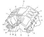
- the perspective view which looked at the cylinder block to which the oil passage structure which concerns on 1st Example of this invention was applied from diagonally downward.
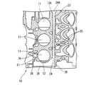
- Sectional drawing which shows the state which attached the cover to the cylinder block of the said Example.
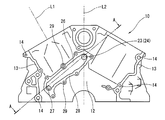
- FIG. 1 to 5 show a single cylinder block 10 of an internal combustion engine according to a first embodiment of the present invention.
- this cylinder block 10 is used for a V-type 6-cylinder internal combustion engine, and is cast from a metal material such as aluminum alloy or cast iron, and three cylinder bores 11 are provided in each of the left and right banks. Arranged along the cylinder row direction (crankshaft direction).
- a flange portion 13 to which a front cover (not shown) is attached is provided at the peripheral portion of the front wall surface 12 of the cylinder block 10, and a cover bolt for fastening and fixing the front cover is inserted into the flange portion 13.
- a plurality of bolt holes 14 are formed.
- An automatic transmission and a torque converter are disposed behind the cylinder block 10.
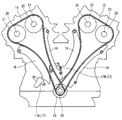
- a chain guide 16 and a chain tensioner 17 are disposed in addition to the timing chain 15 as illustrated in FIG.
- the timing chain 15 is wound around a crank sprocket 19 attached to the front end of the crankshaft 18 and a cam sprocket 21 attached to the front end of the camshaft 20 that drives the intake / exhaust valve.
- the rotation of the shaft 18 is transmitted to the camshaft 20 at a half speed.
- the power transmission structure using the timing chain 15 is not limited to this.
- the two camshafts 20 are individually driven using the two timing chains 15.
- the chain tensioners 17A and 17B are provided for the individual timing chains 15, respectively.
- a main gallery 23 is formed in the cylinder block 10 as a part of an oil gallery through which engine oil flows.
- the main gallery 23 is integrally formed when the cylinder block 10 is cast, and is formed so as to penetrate along the crankshaft direction (cylinder row direction) of the cylinder block 10.
- 24 ⁇ / b> A (see FIG. 4 and the like) is open to the front wall surface 12 and the rear wall surface 12 ⁇ / b> A of the cylinder block 10.
- the opening 24A at the rear end of the main gallery 23 is closed by a plug (not shown).
- a cover 25 is attached to the front wall surface 12 of the cylinder block 10 so as to cover the opening 24 at the front end of the main gallery 23.
- the cover 25 is cast from a metal material such as an aluminum alloy, for example, like the cylinder block 10.
- a sub gallery 26 communicating with the main gallery 23 is formed.
- Engine oil pressurized by an oil pump (not shown) is introduced into the sub gallery 26 through an oil introduction port 27 opened in the front wall surface 12 of the cylinder block 10, and the inside of the sub gallery 26 is moved to the right in FIG. After flowing, it is introduced into the main gallery 23. That is, the sub gallery 26 constitutes an oil introduction oil passage for introducing oil into the main gallery 23.
- a rib 28 integrally projecting forward along the cylinder row direction is formed in an annular shape so as to surround the opening 24 of the main gallery 23.
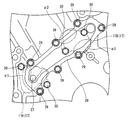
- the peripheral edge of the cover 25 is fixed to the tip of the annular rib 28 using a plurality of bolts 29 (see FIG. 5).
- the rib 28 is formed with a bolt hole 29A through which the plurality of bolts 29 are inserted.
- two chain tensioners 17 (17 ⁇ / b> A and 17 ⁇ / b> B) use tensioner bolts 30 (see FIGS. 5 and 6) as a chain system component that requires oil. Is fixed.
- Each chain tensioner 17 keeps the tension of the timing chain 15 (see FIG. 9) constant by using the oil pressure of oil supplied from the sub gallery 26, as is well known. Since the specific structure of the chain tensioner 17 is known from Japanese Patent Application Laid-Open No. 2011-2042, the description thereof is omitted here.
- An oil supply port 31 (31A, 31B) for supplying oil to each chain tensioner 17 is formed in the cover 25, and the oil is supplied from the sub gallery 26 to each chain tensioner 17 through the oil supply port 31. Supplied. Further, an auxiliary plate 32 for attaching one chain tensioner 17B is joined to the cover 25.
- the auxiliary plate 32 is provided with a reservoir 33 that can store and hold oil, and the oil in the sub gallery 26 is supplied to the chain tensioner 17 via the reservoir 33. Has been.
- the auxiliary plate 32 may be formed integrally with the cover 25.
- FIGS. 11 to 15 show examples of various layout changes of the reservoir section 33.
- the same referential mark is attached
- the reservoir portion 33 is formed on the cover 25 side.
- the reservoir portion 33A is installed only in the chain tensioner 17.
- the cover 25 can be made into a simple plate-like thin shape.
- the reservoir portion 33B is formed in the cover 25 as in the first embodiment.
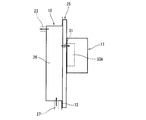
- the reservoir portion 33B of the second embodiment is formed so as to project in a direction away from the sub gallery 26 in the longitudinal direction of the engine (the right direction in FIG. 12). Accordingly, the extension amount of the cover 25 with respect to the wall surface 12 of the cylinder block 10 is increased by the provision of the reservoir portion 33B, and consequently the extension amount D1 of the chain tensioner 17 with respect to the wall surface 12 of the cylinder block 10 is also increased.
- the reservoir portion 33 ⁇ / b> C is formed in the cover 25.
- the reservoir portion 33C is formed by sinking a part of the cover 25 toward the cylinder block 10 so that a part of the cover 25 enters the sub gallery 26.
- the structure is different from that of the third embodiment.
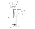
- the amount of protrusion of the cover 25 with respect to the wall surface 12 of the cylinder block 10 is smaller than that in the third embodiment, although the reservoir portion 33C is formed in the cover 25. This can suppress the extension amount D2 (D2 ⁇ D1) of the chain tensioner 17 with respect to the wall surface 12 of the cylinder block 10, thereby suppressing the dimension in the longitudinal direction of the engine and improving the engine mountability.
- the fifth embodiment shown in FIG. 14 is basically the same as the fourth embodiment, but the reservoir portion 33D is formed from the cover 25 to the inside of the chain tensioner 17. In this case, although the longitudinal dimension of the engine is slightly longer, the volume of the reservoir portion 33D can be secured to that extent.
- the shape of the reservoir 33E is set so that the passage sectional area S1 of the sub gallery 26 is constant, as in the first embodiment.
- the shape of the reservoir portion 33E is a shape along the shape of the wall surface 12 of the cylinder block 10 facing the reservoir portion 33E. More specifically, the wall surface 12 of the cylinder block 10 facing the reservoir portion 33E is curved in a cylindrical shape along the cylinder bore 11 adjacent to the wall surface 12, and the cover is provided along the cylindrical wall surface 12. A part of 25 is curved in a cylindrical shape.
- a cover 25 is attached to the front wall surface 12 of the cylinder block 10 so as to cover the opening 24, and the back surface of the cover 25;
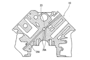
- a sub gallery 26 as an oil gallery communicating with the main gallery 23 is formed between the front wall surface 12 of the cylinder block 10 facing this. Therefore, as compared with the case where a plurality of oil passages (sub-gallerys) 26A communicating with the main gallery 23 are formed in the cylinder block 10 by machining as in the reference example shown in FIG. Further, it is possible to reduce manufacturing costs and work man-hours.
- the sub gallery 26 is provided so as to communicate with the opening 24 on the front side of the main gallery 23, a plug that closes the opening 24 of the main gallery 23 is not required, thereby suppressing the number of parts. Can do.
- the passage area is narrowed, and a portion where the portion connected to the main gallery 23 is sharply bent at a predetermined angle is formed. Since the passage structure is provided, passage resistance is increased. Compared to such a reference example, according to the above embodiment, a large space formed between the cover 25 and the sub gallery 26 can be used to secure a sufficiently large passage area. The passage resistance can be greatly reduced, and a sufficient flow rate can be secured. In addition, since the degree of freedom of the shape is higher than when formed by drilling, a passage structure that smoothly connects from the sub gallery 26 to the main gallery 23 along the outline of the cylinder bore 11 as will be described later. Compared to a passage structure having a sharp bend as in the reference example, the passage resistance can be greatly reduced.
- an oil passage 26A that continues to the main gallery 23 is formed by drilling as in the reference example shown in FIG.
- the oil passage 26A becomes long and difficult to process, and the portion of the front wall of the cylinder block 10 that is thickened for processing increases, which tends to increase the weight and size of the cylinder block 10.
- the structure of this embodiment is extremely useful.
- the chain tensioner 17 as a chain system component is attached to the cover 25, and the oil in the sub gallery 26 is supplied to the chain tensioner 17 via the oil supply port 31 formed in the cover 25. It is configured to supply to.
- the chain tensioner 17 by attaching the chain tensioner 17 to the cover 25 for forming the sub gallery 26 (oil gallery), the space efficiency is improved and the layout is improved as compared with the case where the cover and the chain tensioner are individually set. The degree of freedom can be improved.
- the chain tensioner 17 that keeps the tension of the timing chain constant by hydraulic pressure is used in the above embodiment.
- the chain system component is not limited to this, and the timing chain or the like is used.
- Other chain system components such as an oil jet that ejects oil may be used.
- the reservoir 33 (33C to 33E) for temporarily storing and holding oil is covered. 25 side.
- the capacity of the reservoir portion is sufficiently large as compared with the case where the reservoir portion 33B is provided only in the chain tensioner 17 as in the second embodiment of FIG. can do. For this reason, it is possible to secure the necessary hydraulic pressure immediately after the engine is started and to suppress the fluttering of the timing chain 15, so-called damping, and sufficiently suppress the generation of abnormal noise at the time of starting the engine.
- a part of the cover 25 is arranged so that a part of the cover 25 enters the sub gallery 26.
- the reservoir portion 33 (33C to 33E) is formed by recessing the portion toward the engine main body.
- the shape of the reservoir 33 (33E) is set so that the passage sectional area S1 of the sub gallery 26 is constant. Yes. That is, the wall surface 12 of the engine body facing the reservoir 33 (33E) is curved in a cylindrical shape along the cylinder bore 11 adjacent to the wall surface 12 of the engine body, and extends along the cylindrical wall surface 12. A part of the cover 25 is curved in a cylindrical shape. Thus, by keeping the passage cross-sectional area S1 constant, it is possible to suppress passage resistance and ensure a sufficient flow rate.
- a thick flange portion 28 provided at the peripheral edge of the cover 25 is fixed to the wall surface 12 of the cylinder block 10 as the engine body by a plurality of bolts 29.
- the chain tensioners 17A and 17B which are chain system components, are arranged so as to be placed on the flange portion 28 of the cover 25, as indicated by reference numerals ⁇ 1 and ⁇ 2. That is, part of the chain tensioners 17A and 17B is overlapped with the flange portion 28 of the cover 25. As a result, the support rigidity of the chain tensioner 17 can be increased.
- the chain tensioner 17 receives a reaction force from the timing chain 15, it is likely to be deformed if the support rigidity is low, and there is a concern that abnormal noise is generated due to surface vibration of the cover 25.
- the occurrence of abnormal noise can be suppressed.
- a chain tensioner 17 as a chain system component is attached to the cover 25, and the oil in the sub gallery 26 is supplied to the chain tensioner 17 via an oil supply port 31 formed in the cover 25. ing. Accordingly, in order to supply engine oil to the chain tensioner 17, it is not necessary to separately form an oil passage 26A by drilling in the vicinity of the wall surface of the cylinder block 10 as in the reference example shown in FIG.
- the passage structure for supplying can be a very simple structure.
- ribs 28 projecting along the cylinder row direction are provided on the wall surface 12 of the cylinder block where one end of the main gallery 23 opens, and the opening 24 on the front side of the main gallery 23 is provided.
- the periphery of the cover 25 is fixed to the front end portion of the annular rib 28 by using a bolt 29.
- the passage area of the sub gallery 26 can be sufficiently secured, and the rib 28, the cover 25, and the wall surface 12 of the cylinder block 10
- the closed cross-sectional shape configured can improve the rigidity against the deformation of the cylinder block 10 in the lateral bending direction and the torsional direction caused by the engine vibration caused by the combustion excitation force, and the cylinder bore 11 can be deformed by fastening the head bolt. Can be suppressed.
- the ribs 28 have a simple shape projecting straight in the cylinder row direction, the ribs 28 are formed when the cylinder block 10 is cast by setting the die cutting direction when casting the cylinder block 10 to the cylinder row direction. Can be easily formed integrally.
- the rib 28 crosses the cylinder row center line L1 of the left bank in the drawing and extends in the engine vertical direction through the rotation center of the crankshaft 18 as viewed in the crankshaft direction.
- the cylinder block 10 extends widely in the width direction (left-right direction in FIG. 2) so as to cross the block center line L2.
- the rib 28 into a horizontally long elliptical shape extending in the width direction of the cylinder block 10, in particular, around the cylinder bore 11 adjacent to the front end face of the cylinder block 10 provided with the rib 28.
- the rigidity can be improved, and the deformation of the cylinder bore 11 due to the head bolt fastening can be more reliably suppressed.
- the wall surface 12 of the cylinder block 10 constituting a part of the inner surface of the sub gallery 26 is curved in an arc along the shape of the cylinder bore 11 adjacent to the wall surface 12. It connects smoothly to the main gallery 23.
- a series of oil passages extending from the sub gallery 26 to the main gallery are formed by a gently curved or straight shape without a sharp bend, thereby greatly reducing the passage resistance.
- the flow rate can be sufficiently secured.
- a water jacket 35 through which cooling water flows is formed around the cylinder bore 11 of the cylinder block 10, and the sub-gallery 26 is close to the water jacket 35.
- the sub gallery 26 is formed along the cylindrical wall surface 12 along the outer shape of the cylinder bore 11, the water jacket 35 and the sub gallery 26 formed around the cylinder bore 11 are necessarily close to each other. Are arranged.
- the cylinder block 10 is integrally formed with an oil sump 36 that protrudes forward from the front wall surface 12 in the same manner as the rib 28 described above.
- the oil sump portion 36 is connected to the rib 28 at one end and is formed in a shallow dish shape that opens upward.
- the oil reservoir 36 is arranged so that the oil stored in the oil reservoir 36 is supplied to the reservoir 33 of the chain tensioner 17B via one oil supply port 31B.
- oil can be held in the oil reservoir 36 and the reservoir 33 even after the engine is stopped, and the oil pressure of the chain tensioner 17B can be ensured immediately after the engine is started. Can do.
Landscapes
- Engineering & Computer Science (AREA)
- General Engineering & Computer Science (AREA)
- Mechanical Engineering (AREA)
- Chemical & Material Sciences (AREA)
- Combustion & Propulsion (AREA)
- Cylinder Crankcases Of Internal Combustion Engines (AREA)
- Lubrication Of Internal Combustion Engines (AREA)
- Lubrication Details And Ventilation Of Internal Combustion Engines (AREA)
Abstract
Description
Claims (15)
- 内燃機関の機関本体の壁面にカバーが取り付けられ、
このカバーと、上記機関本体の壁面と、の間に、エンジンオイルが通流するオイルギャラリが形成され、
上記カバーには、チェーンシステム部品が取り付けられるとともに、上記オイルギャラリ内の上記エンジンオイルを上記チェーンシステム部品へ供給するオイル供給口が形成されている内燃機関のオイル通路構造。 - 上記チェーンシステム部品が、油圧によりタイミングチェーンの張力を一定に保持するチェーンテンショナである請求項1に記載の内燃機関のオイル通路構造。
- 上記カバーに上記エンジンオイルを貯留するリザーバ部を設け、このリザーバ部を経由して上記オイルギャラリ内の上記エンジンオイルを上記チェーンシステム部品へ供給するように構成されている請求項1又は2に記載の内燃機関のオイル通路構造。
- 上記カバーの一部が上記オイルギャラリの内部へ入り込むように、このカバーの一部を機関本体側へ陥没させることによって、上記リザーバ部が形成されている請求項3に記載の内燃機関のオイル通路構造。
- 上記オイルギャラリの通路断面積が一定となるように、上記リザーバ部の形状が設定されている請求項3又は4に記載の内燃機関のオイル通路構造。
- 上記リザーバ部の形状を、このリザーバ部に対向する上記機関本体の壁面の形状に沿った形状とした請求項3~5のいずれかに記載の内燃機関のオイル通路構造。
- 上記リザーバ部に対向する上記機関本体の壁面が、この機関本体の壁面に隣接するシリンダボアに沿って円筒状に湾曲している請求項3~6のいずれかに記載の内燃機関のオイル通路構造。
- 上記カバーの周縁部に設けられたフランジ部がボルトにより機関本体の壁面に固定されており、
上記チェーンシステム部品の一部が上記カバーのフランジ部上に配置されている請求項1~7のいずれかに記載の内燃機関のオイル通路構造。 - 上記オイルギャラリが、メインギャラリとサブギャラリとを含み、
このメインギャラリが、上記機関本体のシリンダブロックに形成されて気筒列方向に延在するとともに、
上記メインギャラリの一端が開口する上記シリンダブロックの前側もしくは後側の壁面に上記カバーが取り付けられ、
上記サブギャラリが、上記カバーと、上記シリンダブロックの壁面と、の間に、上記メインギャラリと連通するように形成されており、
上記カバーには、上記サブギャラリ内の上記エンジンオイルを上記チェーンシステム部品へ供給するためのオイル供給口が形成されている請求項1に記載の内燃機関のオイル通路構造。 - 上記サブギャラリが、上記メインギャラリへ上記エンジンオイルを導入するオイル導入油路を構成している請求項9に記載の内燃機関のオイル通路構造。
- 上記メインギャラリの一端が開口する上記シリンダブロックの壁面には、気筒列方向に沿って張り出したリブが、上記メインギャラリの一端が開口する開口部を囲うように円環状に形成されており、
この円環状のリブの先端部に、上記カバーの周縁部が固定されている請求項9又は10に記載の内燃機関のオイル通路構造。 - 上記リブは、クランク軸方向視で気筒中心線を横切るようにシリンダブロックの幅方向に延在している請求項11に記載の内燃機関のオイル通路構造。
- 上記サブギャラリの内面の一部を構成するシリンダブロックの壁面が、この壁面に近接するシリンダボアの形状に沿って湾曲しつつ、上記メインギャラリへと滑らかに接続している請求項9~12のいずれかに記載の内燃機関のオイル通路構造。
- 上記サブギャラリは、上記シリンダブロックに形成されるウォータジャケットに近接して配置されている請求項9~13のいずれかに記載の内燃機関のオイル通路構造。
- 上記メインギャラリが、シリンダブロックの幅方向中央部に配置されている請求項9~14のいずれかに記載の内燃機関のオイル通路構造。
Priority Applications (3)
| Application Number | Priority Date | Filing Date | Title |
|---|---|---|---|
| JP2014544468A JP5737484B2 (ja) | 2012-10-29 | 2013-10-25 | 内燃機関のオイル通路構造 |
| CN201380055218.0A CN104736803B (zh) | 2012-10-29 | 2013-10-25 | 内燃机的油通路构造 |
| US14/438,771 US9677435B2 (en) | 2012-10-29 | 2013-10-25 | Oil passage structure for internal combustion engine |
Applications Claiming Priority (4)
| Application Number | Priority Date | Filing Date | Title |
|---|---|---|---|
| JP2012237374 | 2012-10-29 | ||
| JP2012-237374 | 2012-10-29 | ||
| JP2012-249817 | 2012-11-14 | ||
| JP2012249817 | 2012-11-14 |
Publications (1)
| Publication Number | Publication Date |
|---|---|
| WO2014069345A1 true WO2014069345A1 (ja) | 2014-05-08 |
Family
ID=50627254
Family Applications (1)
| Application Number | Title | Priority Date | Filing Date |
|---|---|---|---|
| PCT/JP2013/078906 Ceased WO2014069345A1 (ja) | 2012-10-29 | 2013-10-25 | 内燃機関のオイル通路構造 |
Country Status (4)
| Country | Link |
|---|---|
| US (1) | US9677435B2 (ja) |
| JP (1) | JP5737484B2 (ja) |
| CN (1) | CN104736803B (ja) |
| WO (1) | WO2014069345A1 (ja) |
Families Citing this family (1)
| Publication number | Priority date | Publication date | Assignee | Title |
|---|---|---|---|---|
| JP6299847B1 (ja) * | 2016-11-21 | 2018-03-28 | マツダ株式会社 | エンジンのオイル通路構造 |
Citations (4)
| Publication number | Priority date | Publication date | Assignee | Title |
|---|---|---|---|---|
| JPH05171912A (ja) * | 1991-12-18 | 1993-07-09 | Suzuki Motor Corp | エンジンの潤滑装置 |
| JP2001073729A (ja) * | 1999-08-31 | 2001-03-21 | Suzuki Motor Corp | 4サイクル船外機 |
| JP2007002706A (ja) * | 2005-06-22 | 2007-01-11 | Aichi Mach Ind Co Ltd | 内燃機関 |
| JP2008180135A (ja) * | 2007-01-24 | 2008-08-07 | Yanmar Co Ltd | 燃料噴射ポンプ潤滑構造 |
Family Cites Families (8)
| Publication number | Priority date | Publication date | Assignee | Title |
|---|---|---|---|---|
| JPH0369347U (ja) * | 1989-11-06 | 1991-07-10 | ||
| JP2601539Y2 (ja) * | 1993-10-15 | 1999-11-22 | 株式会社椿本チエイン | リザーバタンクを平坦又は凸状のプレートで覆ったテンショナ |
| JP3712865B2 (ja) * | 1998-08-12 | 2005-11-02 | 本田技研工業株式会社 | 往復ピストンエンジンのつり合い装置 |
| JP2000266145A (ja) * | 1999-03-18 | 2000-09-26 | Borg Warner Automotive Kk | 油圧テンショナ |
| US7086915B2 (en) * | 2003-01-31 | 2006-08-08 | Suzuki Motor Corporation | Lubricating structure for outboard motors |
| JP3843954B2 (ja) | 2003-03-06 | 2006-11-08 | マツダ株式会社 | エンジンのシリンダブロック構造 |
| CN101655021B (zh) * | 2009-09-21 | 2011-12-14 | 奇瑞汽车股份有限公司 | 一种发动机缸体总成的润滑油路 |
| CN101718215B (zh) * | 2009-10-22 | 2011-06-15 | 柳州五菱柳机动力有限公司 | 一种微型汽车发动机缸体总成的可变正时系统油路 |
-
2013
- 2013-10-25 WO PCT/JP2013/078906 patent/WO2014069345A1/ja not_active Ceased
- 2013-10-25 CN CN201380055218.0A patent/CN104736803B/zh active Active
- 2013-10-25 JP JP2014544468A patent/JP5737484B2/ja active Active
- 2013-10-25 US US14/438,771 patent/US9677435B2/en active Active
Patent Citations (4)
| Publication number | Priority date | Publication date | Assignee | Title |
|---|---|---|---|---|
| JPH05171912A (ja) * | 1991-12-18 | 1993-07-09 | Suzuki Motor Corp | エンジンの潤滑装置 |
| JP2001073729A (ja) * | 1999-08-31 | 2001-03-21 | Suzuki Motor Corp | 4サイクル船外機 |
| JP2007002706A (ja) * | 2005-06-22 | 2007-01-11 | Aichi Mach Ind Co Ltd | 内燃機関 |
| JP2008180135A (ja) * | 2007-01-24 | 2008-08-07 | Yanmar Co Ltd | 燃料噴射ポンプ潤滑構造 |
Also Published As
| Publication number | Publication date |
|---|---|
| CN104736803A (zh) | 2015-06-24 |
| CN104736803B (zh) | 2016-09-21 |
| US9677435B2 (en) | 2017-06-13 |
| US20150267577A1 (en) | 2015-09-24 |
| JP5737484B2 (ja) | 2015-06-17 |
| JPWO2014069345A1 (ja) | 2016-09-08 |
Similar Documents
| Publication | Publication Date | Title |
|---|---|---|
| EP2261492B1 (en) | Engine body, cooling-water pump arrangement structure of engine and method of forming the same | |
| JP4895021B2 (ja) | 可変バルブタイミング機構付エンジンのマウント構造 | |
| JP5175808B2 (ja) | 内燃機関の冷却構造 | |
| JP5737484B2 (ja) | 内燃機関のオイル通路構造 | |
| JP4657134B2 (ja) | 4サイクル空油冷エンジンにおけるオイル通路構造 | |
| JP5806072B2 (ja) | エンジンのオイルジェット構造 | |
| JP2019031963A (ja) | 内燃機関の補機取付構造 | |
| JP2010196566A (ja) | 多気筒エンジンのシリンダヘッド冷却用油路 | |
| JP2000199418A (ja) | 内燃機関のオイル通路構造 | |
| CN109026322B (zh) | 发动机的冷却用油通路构造 | |
| JP2013221609A (ja) | タイミングチェーンの潤滑構造 | |
| US20090186725A1 (en) | Multi-utility camshaft cap for internal combustion engine | |
| US9157365B2 (en) | Internal combustion engine with balancer | |
| JP4705889B2 (ja) | エンジンの駆動伝達機構 | |
| JP2019031964A (ja) | 内燃機関の排気構造 | |
| JP4900593B2 (ja) | 可変バルブタイミング機構付エンジンのオイル通路構造 | |
| EP1344927B1 (en) | Cylinder head | |
| JP2021055585A (ja) | 多気筒内燃機関の本体ブロック | |
| JP2008075507A (ja) | 水冷式多気筒エンジン | |
| CN109026321B (zh) | 发动机的冷却用油通路构造 | |
| JP2018105261A (ja) | シリンダブロックおよびこれを備える内燃機関 | |
| JP4605607B2 (ja) | 水冷式エンジンの冷却水通路構造 | |
| JP2007063992A (ja) | エンジンの前部構造 | |
| JP5314454B2 (ja) | 多気筒エンジンのシリンダヘッド冷却用油路構造 | |
| JPH0348337B2 (ja) |
Legal Events
| Date | Code | Title | Description |
|---|---|---|---|
| 121 | Ep: the epo has been informed by wipo that ep was designated in this application |
Ref document number: 13850757 Country of ref document: EP Kind code of ref document: A1 |
|
| ENP | Entry into the national phase |
Ref document number: 2014544468 Country of ref document: JP Kind code of ref document: A |
|
| WWE | Wipo information: entry into national phase |
Ref document number: 14438771 Country of ref document: US |
|
| NENP | Non-entry into the national phase |
Ref country code: DE |
|
| 122 | Ep: pct application non-entry in european phase |
Ref document number: 13850757 Country of ref document: EP Kind code of ref document: A1 |