WO2014069053A1 - 画像取得装置及び画像取得装置のフォーカス方法 - Google Patents
画像取得装置及び画像取得装置のフォーカス方法 Download PDFInfo
- Publication number
- WO2014069053A1 WO2014069053A1 PCT/JP2013/070051 JP2013070051W WO2014069053A1 WO 2014069053 A1 WO2014069053 A1 WO 2014069053A1 JP 2013070051 W JP2013070051 W JP 2013070051W WO 2014069053 A1 WO2014069053 A1 WO 2014069053A1
- Authority
- WO
- WIPO (PCT)
- Prior art keywords
- image
- imaging
- sample
- focus
- scanning
- Prior art date
Links
Images


Classifications
-
- G—PHYSICS
- G02—OPTICS
- G02B—OPTICAL ELEMENTS, SYSTEMS OR APPARATUS
- G02B7/00—Mountings, adjusting means, or light-tight connections, for optical elements
- G02B7/28—Systems for automatic generation of focusing signals
- G02B7/36—Systems for automatic generation of focusing signals using image sharpness techniques, e.g. image processing techniques for generating autofocus signals
-
- H—ELECTRICITY
- H04—ELECTRIC COMMUNICATION TECHNIQUE
- H04N—PICTORIAL COMMUNICATION, e.g. TELEVISION
- H04N23/00—Cameras or camera modules comprising electronic image sensors; Control thereof
- H04N23/60—Control of cameras or camera modules
- H04N23/67—Focus control based on electronic image sensor signals
- H04N23/673—Focus control based on electronic image sensor signals based on contrast or high frequency components of image signals, e.g. hill climbing method
-
- G—PHYSICS
- G02—OPTICS
- G02B—OPTICAL ELEMENTS, SYSTEMS OR APPARATUS
- G02B21/00—Microscopes
- G02B21/24—Base structure
- G02B21/241—Devices for focusing
- G02B21/244—Devices for focusing using image analysis techniques
-
- G—PHYSICS
- G02—OPTICS
- G02B—OPTICAL ELEMENTS, SYSTEMS OR APPARATUS
- G02B21/00—Microscopes
- G02B21/24—Base structure
- G02B21/241—Devices for focusing
- G02B21/245—Devices for focusing using auxiliary sources, detectors
- G02B21/247—Differential detectors
-
- G—PHYSICS
- G02—OPTICS
- G02B—OPTICAL ELEMENTS, SYSTEMS OR APPARATUS
- G02B21/00—Microscopes
- G02B21/24—Base structure
- G02B21/26—Stages; Adjusting means therefor
-
- G—PHYSICS
- G02—OPTICS
- G02B—OPTICAL ELEMENTS, SYSTEMS OR APPARATUS
- G02B21/00—Microscopes
- G02B21/36—Microscopes arranged for photographic purposes or projection purposes or digital imaging or video purposes including associated control and data processing arrangements
- G02B21/365—Control or image processing arrangements for digital or video microscopes
- G02B21/367—Control or image processing arrangements for digital or video microscopes providing an output produced by processing a plurality of individual source images, e.g. image tiling, montage, composite images, depth sectioning, image comparison
-
- H—ELECTRICITY
- H04—ELECTRIC COMMUNICATION TECHNIQUE
- H04N—PICTORIAL COMMUNICATION, e.g. TELEVISION
- H04N5/00—Details of television systems
- H04N5/222—Studio circuitry; Studio devices; Studio equipment
- H04N5/2224—Studio circuitry; Studio devices; Studio equipment related to virtual studio applications
- H04N5/2226—Determination of depth image, e.g. for foreground/background separation
-
- G—PHYSICS
- G06—COMPUTING; CALCULATING OR COUNTING
- G06T—IMAGE DATA PROCESSING OR GENERATION, IN GENERAL
- G06T2207/00—Indexing scheme for image analysis or image enhancement
- G06T2207/10—Image acquisition modality
- G06T2207/10056—Microscopic image
-
- G—PHYSICS
- G06—COMPUTING; CALCULATING OR COUNTING
- G06T—IMAGE DATA PROCESSING OR GENERATION, IN GENERAL
- G06T2207/00—Indexing scheme for image analysis or image enhancement
- G06T2207/30—Subject of image; Context of image processing
- G06T2207/30004—Biomedical image processing
Definitions
- the present invention relates to an image acquisition device used for acquiring an image of a sample or the like and a focusing method thereof.
- an image acquisition device for example, there is a virtual microscope device in which an imaging region of a sample is divided into a plurality of regions in advance, and each divided region is imaged at a high magnification and then these are combined.
- a focus map for the entire region of the sample is set as an imaging condition when acquiring an image of a sample such as a biological sample, and focus control based on the focus map is performed. Image acquisition of the sample is performed while performing.
- an entire sample is acquired as a macro image using an image acquisition device equipped with a macro optical system.
- an imaging range of the sample is set, the imaging range is divided into a plurality of divided areas, and a focus acquisition position is set for each divided area.
- the sample is transferred to an image acquisition apparatus having a micro optical system, the focus position at the set focus acquisition position is acquired, and a focus map is created from these focus positions.
- This method is a light intensity difference or contrast difference between a light image (front pin) focused before a light image incident on an image acquisition device for image acquisition and a light image focused later (rear pin). Is a method of detecting the shift direction of the focal position with respect to the current height of the objective lens and acquiring the image by moving the objective lens in a direction to cancel the shift.
- a second imaging unit that captures a region in front of the region captured by the first imaging unit, and an image captured by the second imaging unit are used for the first imaging unit.
- the automatic focusing control means for adjusting the in-focus position of the objective lens at the imaging position of the first imaging means and the distance between the divided areas and the moving speed of the sample, the divided areas are imaged by the second imaging means.
- Timing control means for aligning the timing of moving from the position to the imaging position of the first imaging means and the timing of positioning the imaging position of the divided area imaged by the second imaging means on the imaging surface of the first imaging means And are provided.
- the present invention has been made to solve the above problems, and an object of the present invention is to provide an image acquisition apparatus and a focusing method thereof that can suppress an increase in processing time required for imaging by simplifying prefocusing.
- an image acquisition device includes a stage on which a sample is placed, a light source that irradiates light toward the sample, a first optical path for acquiring an optical image of the sample, and A light guide optical system including a light branching unit that branches into a second optical path for focus control; a first imaging unit that acquires a first image by the first light image branched into the first optical path; A second imaging unit that acquires a second image based on the second optical image branched into the second optical path, and a plurality of predetermined imaging positions of the sample by the first imaging unit and the second imaging unit; And a focus control means for analyzing the second image and controlling the focus position of the imaging by the first imaging means based on the analysis result.
- the means stores the control result of the focal position when the scanning control means scans the divided area.
- the control result of the focal position is stored when scanning the divided area, and the initial focal position when the (n + 1) th divided area is scanned is the nth (n is an integer equal to or greater than 1). ) Determine based on the control result stored when scanning the previous divided area.
- the image acquisition apparatus can roughly determine the initial focus position in the divided area to be scanned next using the control result of the divided area that has already been scanned. Thereby, an increase in processing time required for imaging can be suppressed by simplifying the prefocus.
- the focus control means stores the initial focus position when the scanning control means scans the (n + 1) th divided area and stores the initial focal position when scanning the divided area adjacent to the (n + 1) th divided area. You may decide based on a result. Usually, it is estimated that the thickness of the sample in adjacent division areas is continuous. Therefore, the initial focus position can be determined with higher accuracy by using the control result of the focus position in the adjacent divided regions.
- the focus control means determines the initial focus position when the scanning control means scans the (n + 1) th divided area based on the control result stored when scanning the plurality of nth and previous divided areas. You may decide. By using the control results of the focus positions of the plurality of divided areas, the initial focus position can be determined with higher accuracy.
- the first imaging area for obtaining a partial image of the second optical image and the area control means for setting the second imaging area are arranged on the imaging surface of the second imaging means, and the second optical path.
- An optical path difference generating member that generates an optical path difference in the second optical image along the in-plane direction of the imaging surface, and the focus control means includes a contrast value of the image acquired in the first imaging area; It is preferable to store the control result of the focal position at the scanning position where the absolute value of the difference from the contrast value of the image acquired in the second imaging region is equal to or less than a predetermined value. In this way, the control result of the focal position in the vicinity of the in-focus position can be selected and stored, and the initial focal position can be determined with higher accuracy.
- the image acquisition apparatus further includes a macro image acquisition unit that acquires a macro image including the entire sample, and the focus control unit is configured to scan the region where the sample exists based on the macro image. It is preferable to store the control result of the focal position in In this way, it is possible to eliminate the control result of the focal position in the region where no sample exists, and the initial focal position can be determined with higher accuracy.
- the image acquisition apparatus further includes a macro image acquisition unit that acquires a macro image including the entire sample, and the scan control unit determines a first divided region where the region occupied by the sample is maximized based on the macro image. You may scan as a divided area. In this case, more focal position control results can be stored when scanning the first divided area than in other divided areas. Thereby, the initial focus position when scanning the subsequent divided areas can be determined with higher accuracy.
- the focus method of the image acquisition apparatus includes a stage on which a sample is placed, a light source that irradiates light toward the sample, a first optical path for acquiring an optical image of the sample, and A light guide optical system including a light branching unit that branches into a second optical path for focus control; and a first imaging unit that acquires a first image by the first light image branched into the first optical path; , Second imaging means for acquiring a second image based on the second optical image branched into the second optical path, and the imaging position of the sample by the first imaging means and the second imaging means.
- a focus method for an image acquisition device comprising: The scanning control means stores the control result of the focal position when the divided area is scanned, and the scanning control means indicates the initial focal position when the scanning control means scans the (n + 1) th divided area. It is determined based on the control result stored when the nth (n is an integer of 1 or more) previous divided area is scanned.
- the control result of the focal position is stored when scanning the divided area, and the initial focal position when scanning the (n + 1) th divided area is the nth (n is an integer equal to or greater than 1). This is determined based on the control result stored when scanning the previous divided area.
- the image acquisition apparatus can roughly determine the initial focus position in the divided area to be scanned next using the control result of the divided area that has already been scanned. Thereby, an increase in processing time required for imaging can be suppressed by simplifying the prefocus.
- the initial focus position when the scanning control means scans the (n + 1) th divided area is determined based on the control result stored when the divided area adjacent to the (n + 1) th divided area is scanned. May be. Usually, it is estimated that the thickness of the sample in adjacent division areas is continuous. Therefore, the initial focus position can be determined with higher accuracy by using the control result of the focus position in the adjacent divided regions.
- the scanning control means may determine an initial focal position when scanning the (n + 1) th divided area. .
- the initial focus position can be determined with higher accuracy.
- the image acquisition device has a first imaging area for acquiring a partial image of the second optical image on the imaging surface of the second imaging means, an area control means for setting the second imaging area, and a second An optical path difference generating member that is arranged in the optical path of the imaging surface and generates an optical path difference in the second optical image along the in-plane direction of the imaging surface, and a contrast value of the image acquired in the first imaging region; It is preferable to store the control result of the focal position at the scanning position where the absolute value of the difference from the contrast value of the image acquired in the second imaging region is equal to or less than a predetermined value. In this way, the control result of the focal position in the vicinity of the in-focus position can be selected and stored, and the initial focal position can be determined with higher accuracy.
- the image acquisition device further includes a macro image acquisition unit that acquires a macro image including the entire sample, and the control result of the focal position during the period in which the scanning control unit scans the sample existing area based on the macro image. Is preferably stored. In this way, it is possible to eliminate the control result of the focal position in the region where no sample exists, and the initial focal position can be determined with higher accuracy.
- the image acquisition apparatus and macro image acquisition means for acquiring a macro image including the entire sample are further provided, and the divided area where the area occupied by the sample is maximized based on the macro image is scanned as the first divided area. Good.
- more focal position control results can be stored when scanning the first divided area than when scanning is started from another divided area. Thereby, the initial focus position when scanning the subsequent divided areas can be determined with higher accuracy.
- an increase in processing time required for imaging can be suppressed by simplifying prefocus.
- FIG. 1 It is a figure which shows one Embodiment of the macro image acquisition apparatus which comprises the image acquisition apparatus which concerns on this invention. It is a figure which shows one Embodiment of the micro image acquisition apparatus which comprises the image acquisition apparatus which concerns on this invention. It is a figure which shows a 2nd imaging device. It is a figure which shows an example of the combination of an optical path difference production
- FIG. 1 is a diagram showing an embodiment of a macro image acquisition device constituting an image acquisition device according to the present invention.
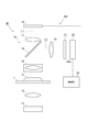
- FIG. 2 is a diagram showing an embodiment of a micro image acquisition device constituting the image acquisition device according to the present invention.
- the image acquisition device M includes a macro image acquisition device M1 that acquires a macro image of the sample S and a micro image acquisition device M2 that acquires a micro image of the sample S. .
- the image acquisition device M sets, for example, a plurality of line-shaped divided regions 40 (see FIG. 11) for the macro image acquired by the macro image acquisition device M1, and each divided region 40 is subjected to high magnification by the micro image acquisition device M2. This is a device that generates a virtual micro image by acquiring and combining them.
- the macro image acquisition apparatus M1 includes a stage 1 on which a sample S is placed as shown in FIG.
- the stage 1 is an XY stage that is driven in the horizontal direction by a motor or actuator such as a stepping motor (pulse motor) or a piezoelectric actuator.
- the sample S to be observed with the image acquisition device M is a biological sample such as a cell, for example, and is placed on the stage 1 in a state of being sealed with a slide glass. By driving the stage 1 in the XY plane, the imaging position with respect to the sample S can be moved.
- the stage 1 can reciprocate between the macro image acquisition device M1 and the micro image acquisition device M2, and has a function of transporting the sample S between both devices.
- macro image acquisition the entire image of the sample S may be acquired by one imaging, or the sample S may be divided into a plurality of regions and imaged.
- the stage 1 may be provided in both the macro image acquisition device M1 and the micro image acquisition device M2.
- a light source 2 that irradiates light toward the sample S and a condenser lens 3 that condenses the light from the light source 2 onto the sample S are disposed.
- the light source 2 may be arranged so as to irradiate light obliquely toward the sample S.
- a light guide optical system 4 that guides a light image from the sample S and an imaging device 5 that captures a light image of the sample S are disposed on the upper surface side of the stage 1.
- the light guide optical system 4 includes an imaging lens 6 that forms an optical image from the sample S on the imaging surface of the imaging device 5.
- the imaging device 5 is an area sensor that can acquire a two-dimensional image, for example.
- the imaging device 5 acquires the entire image of the light image of the sample S incident on the imaging surface via the light guide optical system 4 and stores it in a virtual micro image storage unit 39 described later.
- the micro image acquisition device M2 has a light source 12 and a condenser lens 13 similar to those of the macro image acquisition device M1 on the bottom surface side of the stage 1, as shown in FIG.
- a light guide optical system 14 that guides a light image from the sample S is disposed on the upper surface side of the stage 1.
- the optical system that irradiates the sample S with light from the light source 12 employs an excitation light irradiation optical system for irradiating the sample S with excitation light and a dark field illumination optical system for acquiring a dark field image of the sample S. May be.
- the light guide optical system 4 includes an objective lens 15 disposed so as to face the sample S, and a beam splitter (light branching means) 16 disposed at a subsequent stage of the objective lens 15.
- the objective lens 15 is provided with a motor or actuator such as a stepping motor (pulse motor) or a piezo actuator that drives the objective lens 15 in the Z direction orthogonal to the mounting surface of the stage 1.
- a motor or actuator such as a stepping motor (pulse motor) or a piezo actuator that drives the objective lens 15 in the Z direction orthogonal to the mounting surface of the stage 1.
- the beam splitter 16 is a part that branches the optical image of the sample S into a first optical path L1 for image acquisition and a second optical path L2 for focus control.
- the beam splitter 16 is disposed at an angle of about 45 degrees with respect to the optical axis from the light source 12.
- the optical path passing through the beam splitter 16 is the first optical path L1
- the beam splitter 16 The optical path reflected by 16 is the second optical path.
- an imaging lens 17 that forms an optical image (first optical image) of the sample S that has passed through the beam splitter 16, and an imaging surface is disposed at the imaging position of the imaging lens 17.
- a first imaging device (first imaging means) 18 is arranged.
- the first imaging device 18 is a device that can acquire a one-dimensional image (first image) based on a first light image of the sample S.
- a two-dimensional CCD sensor capable of TDI (Time Delay Integration) drive A line sensor is used.
- the first imaging device 18 is a device that can acquire a two-dimensional image such as a CMOS sensor or a CCD sensor. There may be.
- the first images picked up by the first image pickup device 18 are sequentially stored in a temporary storage memory such as a lane buffer, and then compressed and output to an image generation unit 38 to be described later.
- an optical path difference generation member 21 that causes an optical path difference in the second optical image is disposed in the front stage of the second imaging device 20.
- the field adjustment lens 19 is preferably configured so that the second light image is formed on the second imaging device 20 with the same size as the first light image.
- the second imaging device 20 is a device that can acquire a two-dimensional image (second image) based on the second optical image of the sample S, such as a CMOS (Complementary Metal Oxide Semiconductor) or a CCD (Charge Coupled Device). These sensors are used. A line sensor may be used.
- CMOS Complementary Metal Oxide Semiconductor
- CCD Charge Coupled Device
- the imaging surface 20a of the second imaging device 20 is disposed so as to substantially coincide with the XZ plane orthogonal to the second optical path L2.
- a first imaging area 22A and a second imaging area 22B for acquiring a partial image of the second light image are set on the imaging surface 20a.
- the first imaging region 22A and the second imaging region 22B are oriented in a direction perpendicular to the moving direction (scanning direction: Z direction) of the second optical image on the imaging surface 20a accompanying the scanning of the sample S. Is set.
- the first imaging area 22A and the second imaging area 22B are set with a predetermined interval, and both acquire a part of the second optical image in a line shape.
- the optical image of the same area as the first optical image of the sample S acquired by the first imaging device 18 can be acquired as the second optical image in the first imaging area 22A and the second imaging area 22B.
- the first imaging region 22A and the second imaging region 22B may be set using separate line sensors. In this case, the time required for setting the first imaging region 22A and the second imaging region 22B can be shortened by controlling each line sensor separately.
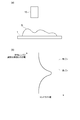
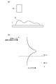
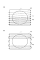
- the optical path difference generating member 21 is a glass member that causes an optical path difference in the second optical image along the in-plane direction of the imaging surface 20a.
- the optical path difference generating member 21 ⁇ / b> A has a prism shape with a triangular cross section, and is arranged so that the top portion substantially coincides with the central portion of the imaging surface 20 a in the Z direction. Therefore, the second optical image incident on the imaging surface 20a has the longest optical path in the center portion in the Z direction on the imaging surface 20a, and the optical path becomes shorter toward both end portions in the Z direction on the imaging surface 20a.
- the optical path difference generating member 21 is arranged so that the surface facing the second imaging device 20 is parallel to the imaging surface (light receiving surface) 20a of the second imaging device. Thereby, refraction of light by the surface facing the second imaging device 20 can be reduced, and the amount of light received by the second imaging device 20 can be ensured.
- the position of the first imaging area 22A and the position of the second imaging area 22B are set so that the first imaging area 22A is a front pin and the second imaging area 22B is a rear pin.
- the focus difference between the front pin and the rear pin is incident on the thickness t1 and refractive index of the optical path difference generation member 21A through which the second optical image incident on the first imaging region 22A passes, and on the second imaging region 22B. This depends on the difference between the thickness t2 and the refractive index of the optical path difference generating member 21A through which the second optical image passes.
- FIG. 5 is a block diagram showing functional components of the image acquisition apparatus.
- the image acquisition apparatus M includes a computer system including a CPU, a memory, a communication interface, a storage unit such as a hard disk, an operation unit 31 such as a keyboard, a monitor 32, and the like.
- a focus control unit 34 As constituent elements, a focus control unit 34, an area control unit 35, an objective lens control unit 36, a stage control unit 37 (scanning control means), an image generation unit 38, and a virtual micro image storage unit 39 are provided. ing.
- the focus control unit 34 is a part that analyzes the second image acquired by the second imaging device 20 and controls the focal position of imaging by the first imaging device 18 based on the analysis result. More specifically, the focus control unit 34, first, in the second imaging device 20, the contrast value of the image acquired in the first imaging region 22A and the contrast value of the image acquired in the second imaging region 22B. Find the difference between
- the focus control unit 34 outputs instruction information indicating that the objective lens 15 is driven in a direction approaching the sample S to the objective lens control unit 36.
- the focus control unit 34 outputs instruction information indicating that the objective lens 15 is driven in a direction away from the sample S to the objective lens control unit 36.
- the area control unit 35 is a part that controls the position of the first imaging area 22 ⁇ / b> A and the position of the second imaging area 22 ⁇ / b> B on the imaging surface 20 a of the second imaging device 20.
- the area control unit 35 first sets the first imaging area 22A at a preset position based on an operation from the operation unit 31, and after the imaging in the first imaging area 22A is performed, the first imaging area 22A is set. The setting of the imaging area 22A is canceled.
- the second imaging area 22B is set with a predetermined interval from the first imaging area 22A in the Z direction (scanning direction), and after the imaging in the second imaging area 22B is performed, the second imaging is performed. The setting of the area 22B is cancelled.
- the area control unit 35 determines at least one of the position of the first imaging area 22A and the position of the second imaging area 22B in the scanning direction within the plane of the imaging surface 20a (here, (Z direction) can be changed. In this case, only one of the position of the first imaging area 22A and the position of the second imaging area 22B may be changed, and the position of the first imaging area 22A and the position of the second imaging area 22B may be changed. Both may be changed. In addition, even if both the position of the first imaging area 22A and the position of the second imaging area 22B are changed while maintaining the distance d between the first imaging area 22A and the second imaging area 22B. Good.
- the first imaging area 22A and the position of the second imaging area 22B By changing the position of the first imaging area 22A and the position of the second imaging area 22B, for example, when the prism-shaped optical path difference generating member 21A as shown in FIG. 4 is used, the first imaging area The thickness t1 of the optical path difference generation member 21A through which the second optical image incident on 22A passes, and the thickness t2 of the optical path difference generation member 21A through which the second optical image incident on the second imaging region 22B passes, Can be changed. Thereby, the space
- the objective lens control unit 36 is a part that controls the driving of the objective lens 15. Upon receiving the instruction information output from the focus control unit 34, the objective lens control unit 36 drives the objective lens 15 in the Z direction according to the content of the instruction information. Thereby, the focal position of the objective lens 15 with respect to the sample S is adjusted.
- the objective lens control unit 36 does not drive the objective lens 15 during the analysis of the focal position by the focus control unit 34, and moves the objective lens 15 in the Z direction until the analysis of the next focal position is started. Drive in only one direction along.
- FIG. 9 is a diagram illustrating the relationship between the distance between the objective lens and the stage 1 with respect to the scanning time of the stage. As shown in the figure, during the scan of the sample S, the focal position analysis period A and the objective lens driving period B based on the analysis result occur alternately. Thus, the analysis accuracy of the focal position can be ensured by not changing the positional relationship between the objective lens 15 and the sample S during the analysis of the focal position.
- the stage control unit 37 is a part that controls the driving of the stage 1. More specifically, the stage control unit 37 scans the stage 1 on which the sample S is placed at a predetermined speed based on an operation from the operation unit 31. The scanning of the stage 1 relatively sequentially moves the imaging field of the sample S in the first imaging device 18 and the second imaging device 20. As shown in FIG. 10A, the scanning direction of the stage 1 is set so that the position of the stage 1 is returned to the scanning start position every time scanning of one divided region 40 is completed, and then the next divided region 40 is set in the same direction. As shown in FIG. 10B, after the scanning of one divided region 40 is completed, the stage 1 is moved in the direction orthogonal to the scanning direction to move to the next divided region. Bidirectional scanning may be performed by scanning 40 in the opposite direction. As described above, the stage control unit 37 scans the imaging field (imaging position) of the sample S by the first imaging device 18 and the second imaging device along the divided region 40.
- each of the deceleration periods F in which the deceleration occurs occurs when scanning outside the divided region 40.
- imaging may be started during the stabilization period D, and the data portion acquired during the stabilization period D after image acquisition may be deleted. Such a method is suitable when using an imaging device that requires idle reading of data.
- the image generation unit 38 is a part that combines the acquired images to generate a virtual micro image.
- the image generation unit 38 sequentially receives the first image output from the first imaging device 18, that is, the image of each divided region 40, and synthesizes them to synthesize the entire image of the sample S. Then, an image having a lower resolution than this is created based on the synthesized image, and the high resolution image and the low resolution image are associated with each other and stored in the virtual micro image storage unit 39.
- an image acquired by the macro image acquisition device M1 may be further associated.
- the virtual micro image may be stored as one image or may be stored as an image divided into a plurality of images.
- the prefocus function is a scanning position (sample start position) at which the sample S first appears in each divided region 40, and the objective is set in advance near the in-focus position (position where the objective lens 15 is focused on the surface of the sample S). This is a function for moving the lens 15.
- the focus control unit 34 performs prefocus processing.
- the focus control unit 34 performs prefocus processing at the sample start position of each divided region 40.
- FIG. 12 shows the sample start position P (region indicated by a rectangle) of each divided region 40.
- 12 (a) and 12 (b) show the sample start position P of each divided region 40 when scanned in the scanning direction shown in FIGS. 10 (a) and 10 (b), respectively.
- the focus control unit 34 specifies the sample start position P based on the macro image acquired by the macro image acquisition device M1, for example. Specifically, the macro image acquired by the macro image acquisition device M1 is binarized using a predetermined threshold, and is automatically set using a predetermined program, or manually by the operator for the macro image displayed on the monitor 32. By the setting, a range (existing region) where the sample S exists is extracted from the macro image.
- the focus control unit 34 specifies the sample start position P of each divided region 40 by specifying a region where the existing region of the sample S extracted from the macro image and each divided region 40 overlap.
- the focus control unit 34 has a special prefocus that is different from the second and subsequent divided regions 40 with respect to the sample start position P of the divided region 40 (first divided region 40) that the stage control unit 37 first scans. Execute the process. For example, the focus control unit 34 measures the contrast value of the first image output from the first imaging device 18 at each position while changing the position of the objective lens 15 in the Z direction, and the contrast value is maximized. And the objective lens 15 is moved to the in-focus position.
- the focus control unit 34 controls the focus position described above, and also controls the focus position of the image pickup by the first image pickup device 18 (hereinafter simply referred to as “focus control”).
- focus control controls the focus position described above, and also controls the focus position of the image pickup by the first image pickup device 18 (hereinafter simply referred to as “focus control”).
- the focus control unit 34 acquires the focus control result by acquiring the height (position in the Z direction) of the objective lens 15 measured in real time by a motor or the like provided in the objective lens 15.
- the focus control unit 34 stores the acquired focus control result in a storage device such as a memory and a hard disk included in the image acquisition device M, for example.
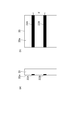
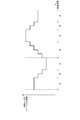
- FIG. 13 is a diagram illustrating an example of a focus control result stored by the focus control unit 34.
- the position for example, the center position of the imaging field
- the focus control unit 34 stores the focus control result is indicated by a different symbol for each divided region 40.
- FIG. 13B is a diagram in which the focus control results (relative height of the objective lens 15 with respect to the stage 1) stored by the focus control unit 34 at each storage position in FIG. 13A are plotted along the imaging direction.
- the shape (thickness) of the surface of the sample S for each divided region 40 can be roughly grasped by storing a plurality of focus control results for each divided region 40.
- the focus control unit 34 sets the focus position (initial focus position) of imaging by the first imaging device 18 at the sample start position P of the (n + 1) th divided region 40 as the nth (n is an integer equal to or greater than 1). This is determined based on the focus control result stored when scanning the previous divided area 40. For example, the focus control unit 34 determines the initial focus position of the (n + 1) -th divided region 40 based on the average value, the intermediate value, and the plane obtained by the calculation using the least square method. Thereafter, the focus control unit 34 outputs instruction information indicating that the objective lens 15 is driven to the determined initial focus position to the objective lens control unit 36 at the sample start position P of the (n + 1) th divided region 40. To do.
- the focus control unit 34 when determining the initial focus position of the (n + 1) -th divided area 40 by the method as described above, the focus control unit 34 performs all the focus control acquired when scanning the n-th and previous divided areas 40.
- the result may be used, but the focus control result to be used may be selected as follows.
- the focus control unit 34 determines the initial focus position of the (n + 1) th divided area 40 based on the focus control result stored in the divided area 40 adjacent to the (n + 1) th divided area 40. Also good. Usually, since the thickness of the sample S in the adjacent divided regions 40 is estimated to be continuous, it is expected that the initial focus position can be determined with higher accuracy by using the focus control result in the adjacent divided regions 40. it can. Further, the focus control unit 34 may determine the initial focus position of the (n + 1) th divided area 40 based on the focus control results stored in the plurality of divided areas 40 before the nth. Accordingly, it can be expected that the initial focus position can be determined with higher accuracy by using the focus control results of a plurality of divided regions.
- the focus control result stored when scanning the adjacent divided regions 40 for example, the surface of the sample S has continuous fine unevenness. It may be the case).
- the focus control result stored in a certain divided area 40 may be used.
- the image acquisition device M holds a selection method corresponding to the type of the sample S as setting information in advance.
- the operator may be able to change the sample S by selecting the type of the sample S via the monitor 32. Accordingly, it is possible to appropriately select the initial focal position of the (n + 1) th divided region 40 according to the type of the sample S and the like.
- the timing at which the focus control unit 34 stores the focus control result may be a predetermined distance interval or a predetermined time interval.
- the focus control unit 34 uses the stage control unit 37 based on the macro image. It is preferable to store the focus control result during the period during which the region where the sample S exists is scanned. Thereby, it is possible to eliminate the focus control result in the region where the sample does not exist, and to determine the initial focus position with higher accuracy.
- the existing region of the sample S can be specified.
- the focus control unit 34 stores a focus control result when the objective lens 15 is positioned in the vicinity of the in-focus position. In other words, the focus control unit 34 determines that the absolute value of the difference between the contrast value of the image (front pin) acquired in the first imaging region 22A and the contrast value of the image acquired in the second imaging region 22B is equal to or less than a predetermined value. It is preferable to store the focus control result at the scanning position. As a result, the focus control result in the vicinity of the in-focus position can be selected and stored, and the initial focus position can be determined with higher accuracy.
- the focus control unit 34 stores a focus control result at a scanning position where the contrast value is equal to or greater than a predetermined value based on the result of analyzing the contrast value of the first image captured by the first imaging device 18. However, the same effect can be obtained.
- the stage control unit 37 may scan the divided area 40 in which the area occupied by the sample S is the maximum based on the macro image as the first divided area.
- the area (area) occupied by the sample S in each divided area 40 can be calculated by specifying the area where the existing area of the sample S extracted from the macro image and each divided area 40 overlap. By comparing the areas calculated in (1), it is possible to identify the divided region 40 in which the region occupied by the sample S is maximized.
- the stage controller 37 scans each divided region 40 from the divided region 40 where the region occupied by the sample S is maximized toward one end of the stage 1 (first to fourth). . Thereafter, the stage control unit 37 scans each divided region 40 from the divided region scanned first and the divided region 40 adjacent to the other end of the stage 1 toward the other end of the stage 1 (fifth to fifth). Nth).
- the stage control unit 37 scans each divided region 40 from the divided region scanned first and the divided region 40 adjacent to the other end of the stage 1 toward the other end of the stage 1 (fifth to fifth). Nth).
- the stage control unit 37 may scan, as the first divided region 40, the divided region 40 in which the sample start position P is positioned closest to the imaging direction. In this case, it is not necessary to calculate and compare the area occupied by the sample S in each divided region 40.
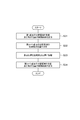
- FIG. 15 is a flowchart showing the operation of the image acquisition apparatus M.
- the macro image of the sample S is acquired by the macro image acquisition device M1 (step S1).
- the acquired macro image is binarized using, for example, a predetermined threshold, and then displayed on the monitor 32, and a micro image is selected from the macro image by automatic setting using a predetermined program or manual setting by an operator.
- a range to be acquired is set (step S2).
- step S3 scanning of stage 1 is started, and micro images for each divided region 40 of the sample S are acquired by the micro image acquisition device M2 (step S3).
- the processing from the start of scanning of the nth divided area to the scanning of the (n + 1) th divided area in step S3 will be described with reference to FIG.
- scanning of stage 1 is started.
- the second imaging device 20 uses the first imaging region 22A and the second imaging region 22B to obtain the difference between the contrast value of the front pin and the contrast value of the rear pin. Based on this, the deviation direction of the objective lens 15 with respect to the sample S is analyzed, and the position of the objective lens 15 is adjusted in real time.
- the focus control result when scanning the divided area 40 is stored (step S31).
- step S32 the initial focus when scanning the (n + 1) -th divided area 40 based on the focus control result stored when scanning the n-th previous area (where the initial value of n is 1).
- step S34 the same processing as step S31 is performed for the (n + 1) th divided region 40.
- the image acquisition apparatus M stores the control result of the focus position when scanning the divided area 40, and sets the initial focus position when scanning the (n + 1) th divided area as the nth position. (N is an integer equal to or greater than 1) This is determined based on the control result stored when the previous divided area 40 is scanned. With such a method, the image acquisition apparatus M can roughly determine the initial focus position in the divided area to be scanned next by using the focus control result of the divided area 40 that has already been scanned. Thereby, an increase in processing time required for imaging can be suppressed by simplifying the prefocus.
- an apparatus for generating a virtual micro image has been exemplified.
- the image acquisition apparatus according to the present invention may be various as long as it acquires an image while scanning a sample at a predetermined speed with a stage or the like. It can be applied to the device.
Abstract
画像取得装置では、分割領域40を走査する際に焦点位置の制御結果を記憶し、第(n+1)番目の分割領域40を走査する際の初期焦点位置を、第n番目(nは1以上の整数)以前の分割領域を走査する際に記憶した制御結果に基づいて決定する。このような手法により、この画像取得装置では、すでに走査を完了した分割領域40の制御結果を利用して次に走査する分割領域40での初期焦点位置を大まかに求めることが可能となる。これにより、プレフォーカスの簡易化により、撮像に要する処理時間の増大を抑制できる。
Description
本発明は、試料等の画像取得に用いられる画像取得装置及びそのフォーカス方法に関する。
画像取得装置として、例えば試料の撮像領域を予め複数の領域に分割し、各分割領域を高倍率で撮像した後、これらを合成するバーチャル顕微鏡装置がある。このようなバーチャル顕微鏡での画像取得では、従来、生体サンプルなどの試料の画像を取得する際の撮像条件として、試料の全領域を対象とする焦点マップが設定され、焦点マップに基づく焦点制御を行いつつ試料の画像取得が行われている。
焦点マップの作成には、まず、マクロ光学系を備える画像取得装置を用い、試料全体をマクロ画像として取得する。次に、取得したマクロ画像を用い、試料の撮像範囲を設定すると共に、撮像範囲を複数の分割領域に分割し、各分割領域に対して焦点取得位置を設定する。焦点取得位置の設定の後、ミクロ光学系を備える画像取得装置に試料を移し、設定された焦点取得位置における焦点位置を取得し、これらの焦点位置から焦点マップを作成する。
しかしながら、このような焦点マップを作成するにあたっては、処理に時間を要するという問題があった。また、取得する焦点の間隔や数を抑えれば処理に要する時間は短縮されるが、その場合にはフォーカス精度が低下するという問題があった。そのため、焦点位置を取得しつつ試料の高倍率画像を取得するダイナミックフォーカスの開発が進められている。この方式は、画像取得用の撮像装置に入射する光像よりも前に焦点が合った光像(前ピン)と、後に焦点が合った光像(後ピン)との光強度差或いはコントラスト差に基づいて現在の対物レンズの高さに対する焦点位置のずれ方向を検出し、ずれをキャンセルする方向に対物レンズを移動させて画像を取得する方式である。
例えば特許文献1に記載の顕微鏡システムでは、第1の撮像手段が撮像する領域よりも手前の領域を撮像する第2の撮像手段と、第2の撮像手段で撮像された画像に基づいて、第1の撮像手段の撮像位置での対物レンズの合焦位置を調整する自動合焦制御手段と、分割領域間の距離と試料の移動速度とに応じて、分割領域が第2の撮像手段の撮像位置から第1の撮像手段の撮像位置まで移動するタイミングと、第2の撮像手段で撮像された分割領域の結像位置を第1の撮像手段の撮像面に位置させるタイミングとを揃えるタイミング制御手段とが設けられている。
ここで、各分割領域において、上記のようなダイナミックフォーカスの方式により撮像位置を所定の速度で移動させつつ、焦点位置を調整しながら各分割領域の撮像を行う場合には、各分割領域で撮像対象の試料が最初に出現する走査位置においては、予め合焦位置の近傍に対物レンズを移動させておく処理(プレフォーカス)を行う必要がある。これは、試料が最初に出現する走査位置において対物レンズの位置が合焦位置の近傍から大きくずれていると、ダイナミックフォーカスによる焦点位置の制御が発散してしまうおそれがあるためである。
しかしながら、プレフォーカスの実行に時間を要すると、特に、撮像範囲を多数の分割領域に分割した場合に、各回のプレフォーカスの実行によって撮像に要する処理時間が増大してしまうという問題がある。
本発明は、上記課題の解決のためになされたものであり、プレフォーカスの簡易化により、撮像に要する処理時間の増大を抑制できる画像取得装置及びそのフォーカス方法を提供することを目的とする。
上記課題の解決のため、本発明に係る画像取得装置は、試料が載置されるステージと、試料に向けて光を照射する光源と、試料の光像を画像取得用の第1の光路及び焦点制御用の第2の光路に分岐する光分岐手段を含む導光光学系と、第1の光路に分岐された第1の光像による第1の画像を取得する第1の撮像手段と、第2の光路に分岐された第2の光像による第2の画像を取得する第2の撮像手段と、第1の撮像手段及び第2の撮像手段による試料の撮像位置を予め定められた複数の分割領域に沿って走査する走査制御手段と、第2の画像を解析し、その解析結果に基づいて第1の撮像手段による撮像の焦点位置を制御する焦点制御手段と、を備え、焦点制御手段は、走査制御手段が分割領域を走査する際に焦点位置の制御結果を記憶し、走査制御手段が第(n+1)番目の分割領域を走査する際の初期焦点位置を、走査制御手段が第n番目(nは1以上の整数)以前の分割領域を走査する際に記憶した制御結果に基づいて決定することを特徴としている。
この画像取得装置では、分割領域を走査する際に焦点位置の制御結果を記憶し、第(n+1)番目の分割領域を走査する際の初期焦点位置を、第n番目(nは1以上の整数)以前の分割領域を走査する際に記憶した制御結果に基づいて決定する。このような手法により、この画像取得装置では、すでに走査を完了した分割領域の制御結果を利用して次に走査する分割領域での初期焦点位置を大まかに求めることが可能となる。これにより、プレフォーカスの簡易化により、撮像に要する処理時間の増大を抑制できる。
また、焦点制御手段は、走査制御手段が第(n+1)番目の分割領域を走査する際の初期焦点位置を、第(n+1)番目の分割領域に隣接する分割領域を走査する際に記憶した制御結果に基づいて決定してもよい。通常、隣接する分割領域同士における試料の厚さは連続していると推定される。したがって、隣接する分割領域における焦点位置の制御結果を用いることにより、初期焦点位置をより精度良く決定できる。
また、焦点制御手段は、第n番目以前の複数の分割領域を走査する際に記憶した制御結果に基づいて、走査制御手段が第(n+1)番目の分割領域を走査する際の初期焦点位置を決定してもよい。複数の分割領域の焦点位置の制御結果を用いることで、初期焦点位置をより精度良く決定できる。
また、第2の撮像手段の撮像面に、第2の光像の一部画像を取得する第1の撮像領域及び第2の撮像領域を設定する領域制御手段と、第2の光路に配置され、撮像面の面内方向に沿って第2の光像に光路差を生じさせる光路差生成部材と、を更に備え、焦点制御手段は、第1の撮像領域で取得した画像のコントラスト値と、第2の撮像領域で取得した画像のコントラスト値との差分の絶対値が所定値以下となる走査位置で焦点位置の制御結果を記憶することが好ましい。こうすると、合焦位置の近傍にある焦点位置の制御結果を選択して記憶することができ、初期焦点位置をより精度良く決定できる。
また、上記画像取得装置は、試料全体を含むマクロ画像を取得するマクロ画像取得手段を更に備え、焦点制御手段は、マクロ画像に基づいて走査制御手段が試料の存在領域を走査している期間中に焦点位置の制御結果を記憶することが好ましい。こうすると、試料が存在しない領域での焦点位置の制御結果を排除でき、初期焦点位置を一層精度良く決定できる。
また、上記画像取得装置は、試料全体を含むマクロ画像を取得するマクロ画像取得手段を更に備え、走査制御手段は、マクロ画像に基づいて試料が占める領域が最大となる分割領域を第1番目の分割領域として走査してもよい。この場合、第1番目の分割領域の走査時に、他の分割領域と比較してより多くの焦点位置の制御結果を記憶できる。これにより、以降の分割領域を走査する際の初期焦点位置を一層精度良く決定できる。
また、本発明に係る画像取得装置のフォーカス方法は、試料が載置されるステージと、前記試料に向けて光を照射する光源と、前記試料の光像を画像取得用の第1の光路及び焦点制御用の第2の光路に分岐する光分岐手段を含む導光光学系と、前記第1の光路に分岐された第1の光像による第1の画像を取得する第1の撮像手段と、前記第2の光路に分岐された第2の光像による第2の画像を取得する第2の撮像手段と、前記第1の撮像手段及び前記第2の撮像手段による前記試料の撮像位置を予め定められた複数の分割領域に沿って走査する走査制御手段と、前記第2の画像を解析し、その解析結果に基づいて前記第1の撮像手段による撮像の焦点位置を制御する焦点制御手段と、を備えた画像取得装置のフォーカス方法であって、前記走査制御手段が前記分割領域を走査する際の前記焦点位置の制御結果を記憶し、前記走査制御手段が第(n+1)番目の分割領域を走査する際の初期焦点位置を、前記走査制御手段が第n番目(nは1以上の整数)以前の分割領域を走査する際に記憶した前記制御結果に基づいて決定することを特徴としている。
このフォーカス方法では、分割領域を走査する際に焦点位置の制御結果を記憶し、第(n+1)番目の分割領域を走査する際の初期焦点位置を、第n番目(nは1以上の整数)以前の分割領域を走査する際に記憶した制御結果に基づいて決定する。このような手法により、この画像取得装置では、すでに走査を完了した分割領域の制御結果を利用して次に走査する分割領域での初期焦点位置を大まかに求めることが可能となる。これにより、プレフォーカスの簡易化により、撮像に要する処理時間の増大を抑制できる。
また、走査制御手段が第(n+1)番目の分割領域を走査する際の初期焦点位置を、第(n+1)番目の分割領域に隣接する分割領域を走査する際に記憶した制御結果に基づいて決定してもよい。通常、隣接する分割領域同士における試料の厚さは連続していると推定される。したがって、隣接する分割領域における焦点位置の制御結果を用いることにより、初期焦点位置をより精度良く決定できる。
また、第n番目以前の複数の分割領域を走査する際に記憶した制御結果に基づいて、走査制御手段が第(n+1)番目の分割領域を走査する際の初期焦点位置を決定してもよい。複数の分割領域の焦点位置の制御結果を用いることで、初期焦点位置をより精度良く決定できる。
また、画像取得装置が、第2の撮像手段の撮像面に、第2の光像の一部画像を取得する第1の撮像領域及び第2の撮像領域を設定する領域制御手段と、第2の光路に配置され、撮像面の面内方向に沿って第2の光像に光路差を生じさせる光路差生成部材と、を更に備え、第1の撮像領域で取得した画像のコントラスト値と、第2の撮像領域で取得した画像のコントラスト値との差分の絶対値が所定値以下となる走査位置で焦点位置の制御結果を記憶することが好ましい。こうすると、合焦位置の近傍にある焦点位置の制御結果を選択して記憶することができ、初期焦点位置をより精度良く決定できる。
また、画像取得装置が、試料全体を含むマクロ画像を取得するマクロ画像取得手段を更に備え、マクロ画像に基づいて走査制御手段が試料の存在領域を走査している期間中に焦点位置の制御結果を記憶することが好ましい。こうすると、試料が存在しない領域での焦点位置の制御結果を排除でき、初期焦点位置を一層精度良く決定できる。
また、画像取得装置、試料全体を含むマクロ画像を取得するマクロ画像取得手段を更に備え、マクロ画像に基づいて試料が占める領域が最大となる分割領域を第1番目の分割領域として走査してもよい。この場合、第1番目の分割領域の走査時に、他の分割領域から走査を開始する場合と比較してより多くの焦点位置の制御結果を記憶できる。これにより、以降の分割領域を走査する際の初期焦点位置を一層精度良く決定できる。
本発明によれば、プレフォーカスの簡易化により、撮像に要する処理時間の増大を抑制できる。
以下、図面を参照しながら、本発明に係る画像取得装置及び画像取得装置のフォーカス方法の好適な実施形態について詳細に説明する。
図1は、本発明に係る画像取得装置を構成するマクロ画像取得装置の一実施形態を示す図である。また、図2は、本発明に係る画像取得装置を構成するミクロ画像取得装置の一実施形態を示す図である。図1及び図2に示すように、画像取得装置Mは、試料Sのマクロ画像を取得するマクロ画像取得装置M1と、試料Sのミクロ画像を取得するミクロ画像取得装置M2とによって構成されている。画像取得装置Mは、マクロ画像取得装置M1で取得したマクロ画像に対して例えばライン状の複数の分割領域40(図11参照)を設定し、各分割領域40をミクロ画像取得装置M2で高倍率に取得して合成することにより、バーチャルマイクロ画像を生成する装置である。
マクロ画像取得装置M1は、図1に示すように、試料Sが載置されるステージ1を備えている。ステージ1は、例えばステッピングモータ(パルスモータ)或いはピエゾアクチュエータなどのモータやアクチュエータによって水平方向に駆動するXYステージである。画像取得装置Mで観察する試料Sは、例えば細胞などの生体サンプルであり、スライドガラスに密封された状態でステージ1に載置される。このステージ1をXY面内で駆動させることにより、試料Sに対する撮像位置を移動させることができる。
ステージ1は、マクロ画像取得装置M1とミクロ画像取得装置M2との間を往復可能となっており、両装置間で試料Sを搬送する機能を有している。なお、マクロ画像取得においては、試料Sの全体画像を1度の撮像で取得してもよく、試料Sを複数の領域に分割して撮像してもよい。また、ステージ1は、マクロ画像取得装置M1及びミクロ画像取得装置M2の双方にそれぞれ設けておいてもよい。
ステージ1の底面側には、試料Sに向けて光を照射する光源2と、光源2からの光を試料Sに集光する集光レンズ3とが配置されている。光源2は、試料Sに向けて斜めに光を照射するように配置されていてもよい。また、ステージ1の上面側には、試料Sからの光像を導光する導光光学系4と、試料Sの光像を撮像する撮像装置5とが配置されている。導光光学系4は、試料Sからの光像を撮像装置5の撮像面に結像させる結像レンズ6を有している。また、撮像装置5は、例えば2次元画像を取得可能なエリアセンサである。撮像装置5は、導光光学系4を経て撮像面に入射した試料Sの光像の全体画像を取得し、後述のバーチャルマイクロ画像格納部39に格納する。
ミクロ画像取得装置M2は、図2に示すように、ステージ1の底面側にマクロ画像取得装置M1と同様の光源12及び集光レンズ13を有している。また、ステージ1の上面側には、試料Sからの光像を導光する導光光学系14が配置されている。光源12からの光を試料Sに照射させる光学系には、試料Sに励起光を照射するための励起光照射光学系や試料Sの暗視野画像を取得するための暗視野照明光学系を採用してもよい。
導光光学系4は、試料Sと対峙して配置された対物レンズ15と、対物レンズ15の後段に配置されたビームスプリッタ(光分岐手段)16とを有している。対物レンズ15には、ステージ1の載置面に直交するZ方向に対物レンズ15を駆動するステッピングモータ(パルスモータ)或いはピエゾアクチュエータなどのモータやアクチュエータが設けられている。これらの駆動手段によって対物レンズ15のZ方向の位置を変えることにより、試料Sの画像取得における撮像の焦点位置が調整可能になっている。なお、焦点位置の調整は、ステージ1のZ方向の位置を変えてもよく、対物レンズ15及びステージ1の双方のZ方向の位置を変えてもよい。
ビームスプリッタ16は、試料Sの光像を画像取得用の第1の光路L1と焦点制御用の第2の光路L2とに分岐する部分である。このビームスプリッタ16は、光源12からの光軸に対しておよそ45度の角度で配置されており、図2において、ビームスプリッタ16を通過する光路が第1の光路L1となっており、ビームスプリッタ16で反射する光路が第2の光路となっている。
第1の光路L1には、ビームスプリッタ16を通過した試料Sの光像(第1の光像)を結像させる結像レンズ17と、結像レンズ17の結像位置に撮像面を配置した第1の撮像装置(第1の撮像手段)18とが配置されている。第1の撮像装置18は、試料Sの第1の光像による1次元画像(第1の画像)を取得可能な装置であり、例えばTDI(Time Delay Integration)駆動が可能な2次元CCDセンサやラインセンサが用いられる。また、ステージ1を一定の速度で制御しながら、試料Sの画像を順次取得する方式であれば、第1の撮像装置18は、CMOSセンサやCCDセンサなどの2次元画像を取得可能な装置であってもよい。第1の撮像装置18で撮像された第1の画像は、レーンバッファなどの一時保存メモリに順次保存された後、圧縮されて後述の画像生成部38に出力される。
一方、第2の光路L2には、ビームスプリッタ16で反射した試料の光像(第2の光像)を縮小する視野調整レンズ19と、第2の撮像装置(第2の撮像手段)20とが配置されている。また、第2の撮像装置20の前段には、第2の光像に光路差を生じさせる光路差生成部材21が配置されている。視野調整レンズ19は、第2の光像が第1の光像と同程度の大きさで第2の撮像装置20に結像するように構成されていることが好ましい。
第2の撮像装置20は、試料Sの第2の光像による2次元画像(第2の画像)を取得可能な装置であり、例えばCMOS(Complementary Metal Oxide Semiconductor)やCCD(Charge Coupled Device)などのセンサが用いられる。また、ラインセンサを用いてもよい。
第2の撮像装置20の撮像面20aは、第2の光路L2に直交するXZ面と略一致するように配置されている。この撮像面20aには、図3に示すように、第2の光像の一部画像を取得する第1の撮像領域22A及び第2の撮像領域22Bが設定されている。第1の撮像領域22A及び第2の撮像領域22Bは、試料Sの走査に伴う撮像面20a上での第2の光像の移動方向(走査方向:Z方向)に対して垂直となる向きに設定される。第1の撮像領域22Aと第2の撮像領域22Bとは、所定の間隔をもって設定されており、いずれも第2の光像の一部をライン状に取得する。これにより、第1の撮像装置18で取得される試料Sの第1の光像と同じ領域の光像を第2の光像として第1の撮像領域22A及び第2の撮像領域22Bで取得できる。なお、第1の撮像領域22Aと第2の撮像領域22Bとを別々のラインセンサを用いて設定してもよい。この場合、各ラインセンサを別々に制御することで、第1の撮像領域22A及び第2の撮像領域22Bの設定に要する時間を短縮させることができる。
光路差生成部材21は、撮像面20aの面内方向に沿って第2の光像に光路差を生じさせるガラス部材である。図4に示す例では、光路差生成部材21Aは、断面三角形のプリズム状をなしており、撮像面20aのZ方向の中央部分に頂部が略一致するように配置されている。したがって、撮像面20aに入射する第2の光像は、撮像面20aにおけるZ方向の中央部分で最も光路が長くなり、撮像面20aにおけるZ方向の両端部分に向かうほど光路が短くなる。また、光路差生成部材21は、第2の撮像装置20と対向する面が第2の撮像装置の撮像面(受光面)20aと平行となるように配置されることが好ましい。これにより、第2の撮像装置20と対向する面による光の屈折を低減でき、第2の撮像装置20で受光する光量を確保することができる。
これにより、第2の撮像装置20では、第1の撮像領域22Aの位置と第2の撮像領域22Bの位置に基づいて、第1の撮像装置18に入射する第1の光像よりも前に焦点が合った光像(前ピン)と、後に焦点が合った光像(後ピン)とを取得できる。本実施形態では、例えば第1の撮像領域22Aが前ピンとなり、第2の撮像領域22Bが後ピンとなるように第1の撮像領域22Aの位置と第2の撮像領域22Bの位置とが設定される。前ピンと後ピンとの間のフォーカス差は、第1の撮像領域22Aに入射する第2の光像が通過する光路差生成部材21Aの厚さt1及び屈折率と、第2の撮像領域22Bに入射する第2の光像が通過する光路差生成部材21Aの厚さt2及び屈折率との差に依存する。
図5は、画像取得装置の機能的な構成要素を示すブロック図である。同図に示すように、画像取得装置Mは、CPU、メモリ、通信インタフェイス、ハードディスクといった格納部、キーボードなどの操作部31、モニタ32等を備えたコンピュータシステムを備え、制御部33の機能的な構成要素として、焦点制御部34と、領域制御部35と、対物レンズ制御部36と、ステージ制御部37(走査制御手段)と、画像生成部38と、バーチャルマイクロ画像格納部39とを備えている。
焦点制御部34は、第2の撮像装置20で取得した第2の画像を解析し、その解析結果に基づいて第1の撮像装置18による撮像の焦点位置を制御する部分である。より具体的には、焦点制御部34は、まず、第2の撮像装置20において、第1の撮像領域22Aで取得した画像のコントラスト値と、第2の撮像領域22Bで取得した画像のコントラスト値との差分を求める。
ここで、図6に示すように、試料Sの表面に対して対物レンズ15の焦点位置が合っている場合、第1の撮像領域22Aで取得した前ピンの画像コントラスト値と第2の撮像領域22Bで取得した後ピンの画像コントラスト値とが略一致し、これらの差分値はほぼゼロとなる。
一方、図7に示すように、試料Sの表面までの距離が対物レンズ15の焦点距離よりも長い場合、第1の撮像領域22Aで取得した前ピンの画像コントラスト値よりも第2の撮像領域22Bで取得した後ピンの画像コントラスト値の方が大きくなり、これらの差分値はプラスとなる。この場合、焦点制御部34は、対物レンズ制御部36に対し、対物レンズ15を試料Sに近づける向きに駆動する旨の指示情報を出力する。
また、図8に示すように、試料Sの表面までの距離が対物レンズ15の焦点距離よりも短い場合、第1の撮像領域22Aで取得した前ピンの画像コントラスト値よりも第2の撮像領域22Bで取得した後ピンの画像コントラスト値の方が小さくなり、これらの差分値はマイナスとなる。この場合、焦点制御部34は、対物レンズ制御部36に対し、対物レンズ15を試料Sから遠ざける向きに駆動する旨の指示情報を出力する。
領域制御部35は、第2の撮像装置20の撮像面20aにおける第1の撮像領域22Aの位置及び第2の撮像領域22Bの位置を制御する部分である。領域制御部35は、操作部31からの操作に基づき、予め設定された位置にまず第1の撮像領域22Aを設定し、第1の撮像領域22Aでの撮像が行われた後、第1の撮像領域22Aの設定を解除する。次に、第1の撮像領域22AからZ方向(走査方向)に所定の間隔をもって第2の撮像領域22Bを設定し、第2の撮像領域22Bでの撮像が行われた後、第2の撮像領域22Bの設定を解除する。
また、領域制御部35は、操作部31からの操作に基づき、第1の撮像領域22Aの位置と第2の撮像領域22Bの位置の少なくとも一方を撮像面20aの面内の走査方向(ここではZ方向)に沿って変更することができる。この場合、第1の撮像領域22Aの位置及び第2の撮像領域22Bの位置のいずれか一方のみを変更してもよく、第1の撮像領域22Aの位置及び第2の撮像領域22Bの位置の双方を変更してもよい。また、第1の撮像領域22Aと第2の撮像領域22Bとの間の間隔dを維持したまま、第1の撮像領域22Aの位置及び第2の撮像領域22Bの位置の双方を変更してもよい。
第1の撮像領域22Aの位置と第2の撮像領域22Bの位置を変更することにより、例えば図4に示したようなプリズム状の光路差生成部材21Aを用いる場合には、第1の撮像領域22Aに入射する第2の光像が通過する光路差生成部材21Aの厚さt1と、第2の撮像領域22Bに入射する第2の光像が通過する光路差生成部材21Aの厚さt2とを変化させることができる。これにより、前ピン及び後ピンの間隔が変わり、コントラスト値の差分を求める際の分解能を調整できる。
対物レンズ制御部36は、対物レンズ15の駆動を制御する部分である。対物レンズ制御部36は、焦点制御部34から出力される指示情報を受け取ると、指示情報の内容に従って、対物レンズ15をZ方向に駆動させる。これにより、試料Sに対する対物レンズ15の焦点位置が調整される。
なお、対物レンズ制御部36は、焦点制御部34による焦点位置の解析中は対物レンズ15の駆動は行わず、また、次の焦点位置の解析が開始されるまで、対物レンズ15をZ方向に沿って一方向にのみ駆動させる。図9は、ステージの走査時間に対する対物レンズとステージ1との距離の関係を示す図である。同図に示すように、試料Sの走査中は、焦点位置の解析期間Aと、解析結果に基づく対物レンズ駆動期間Bとが交互に生じることとなる。このように、焦点位置の解析中に対物レンズ15と試料Sとの位置関係を変化させないことで、焦点位置の解析精度を担保できる。
ステージ制御部37は、ステージ1の駆動を制御する部分である。より具体的には、ステージ制御部37は、操作部31からの操作に基づき、試料Sが載置されたステージ1を所定の速度で走査させる。このステージ1の走査により、第1の撮像装置18及び第2の撮像装置20での試料Sの撮像視野が相対的に順次移動する。ステージ1の走査方向は、図10(a)に示すように、一つの分割領域40の走査が終了する度にステージ1の位置を走査開始位置まで戻してから次の分割領域40を同一方向に走査する一方向走査であってもよく、図10(b)に示すように、一つの分割領域40の走査が終了した後、ステージ1を走査方向と直交する方向に移動させて次の分割領域40を反対方向に走査する双方向走査であってもよい。このように、ステージ制御部37は、第1の撮像装置18及び第2の撮像装置による試料Sの撮像視野(撮像位置)を分割領域40に沿って走査する。
また、画像取得の間のステージ1の走査速度は一定であるが、実際には走査の開始直後にステージ1の振動等の影響によって走査速度が不安定な期間が存在する。このため、図11に示すように、分割領域40よりも長い走査幅を設定し、ステージ1が加速する加速期間C、ステージ1の走査速度が安定化するまでの安定化期間D、及びステージ1が減速する減速期間Fのそれぞれが、分割領域40よりも外側を走査しているときに生じるようにすることが好ましい。これにより、ステージ1の走査速度が一定となる一定速度期間Eに合わせて画像取得を行うことが可能となる。なお、安定化期間D中に撮像を開始し、画像取得後に安定化期間D中に取得したデータ部分を削除するようにしてもよい。このような手法は、データの空読みが必要な撮像装置を用いる場合に好適である。
画像生成部38は、取得した画像を合成してバーチャルマイクロ画像を生成する部分である。画像生成部38は、第1の撮像装置18から出力される第1の画像、すなわち、各分割領域40の画像を順次受け取り、これらを合成して試料Sの全体の画像を合成する。そして、この合成画像に基づいてこれよりも低い解像度の画像を作成し、高解像度の画像と低解像度の画像とを関連付けてバーチャルマイクロ画像格納部39に格納する。バーチャルマイクロ画像格納部39では、マクロ画像取得装置M1で取得した画像も更に関連付けてもよい。バーチャルマイクロ画像は、1枚の画像として格納してもよく、複数に分割された画像として格納してもよい。
続いて、画像取得装置Mが有するプレフォーカス機能について説明する。プレフォーカス機能とは、各分割領域40で試料Sが最初に出現する走査位置(試料開始位置)で、予め合焦位置(試料Sの表面に対する対物レンズ15の焦点が合う位置)の近傍に対物レンズ15を移動させておく機能である。画像取得装置Mでは、焦点制御部34がプレフォーカス処理を実行する。
焦点制御部34は、各分割領域40の試料開始位置でプレフォーカス処理を実行する。図12に、各分割領域40の試料開始位置P(矩形で示される領域)を示す。図12(a)及び図12(b)はそれぞれ、図10(a)及び図10(b)に示す走査方向に走査される場合の各分割領域40の試料開始位置Pを示す。
焦点制御部34は、例えばマクロ画像取得装置M1が取得したマクロ画像に基づいて試料開始位置Pを特定する。具体的には、マクロ画像取得装置M1により取得されたマクロ画像を所定の閾値を用いて二値化し、所定のプログラムを用いた自動設定、又はモニタ32に表示されたマクロ画像に対する操作者による手動設定により、マクロ画像から試料Sが存在する範囲(存在領域)を抽出する。焦点制御部34は、マクロ画像から抽出された試料Sの存在領域と各分割領域40とが重なる領域を特定することにより、各分割領域40の試料開始位置Pを特定する。
焦点制御部34は、ステージ制御部37が最初に走査する分割領域40(第1番目の分割領域40)の試料開始位置Pについては、第2番目以降の分割領域40とは異なる特殊なプレフォーカス処理を実行する。例えば焦点制御部34は、対物レンズ15のZ方向の位置を変化させながら、各位置において第1の撮像装置18から出力される第1の画像のコントラスト値を計測し、上記コントラスト値が最大となる位置(合焦位置)を特定し、対物レンズ15を合焦位置に移動させる。
焦点制御部34は、ステージ制御部37が分割領域40を走査する際、上述の焦点位置の制御を行うと共に、第1の撮像装置18による撮像の焦点位置の制御結果(以下、単に「焦点制御結果」と記す。)として、ステージ1に対する対物レンズ15の高さを取得し、記憶する。焦点制御部34は、例えば、対物レンズ15が備えるモータ等でリアルタイムに計測される対物レンズ15の高さ(Z方向の位置)を取得することで、焦点制御結果を取得する。また、焦点制御部34は、取得した焦点制御結果を、例えば画像取得装置Mが備えるメモリ及びハードディスク等の記憶装置に記憶する。
図13は、焦点制御部34が記憶した焦点制御結果の例を示す図である。図13(a)には、焦点制御部34が焦点制御結果を記憶した位置(例えば撮像視野の中央位置)を分割領域40ごとに異なる記号で示している。図13(b)には、図13(a)の各記憶位置で焦点制御部34が記憶した焦点制御結果(ステージ1に対する対物レンズ15の相対高さ)を撮像方向に沿ってプロットした図である図13(b)に示す通り、分割領域40ごとに焦点制御結果を複数記憶することで分割領域40ごとの試料Sの表面の形状(厚み)を大まかに把握できる。
焦点制御部34は、第(n+1)番目の分割領域40の試料開始位置Pにおける第1の撮像装置18による撮像の焦点位置(初期焦点位置)を、第n番目(nは1以上の整数)以前の分割領域40を走査する際に記憶した焦点制御結果に基づいて決定する。例えば、焦点制御部34は、これらの焦点制御結果の平均値、中間値、最小二乗法による計算等により求まる平面に基づいて第(n+1)番目の分割領域40の初期焦点位置を決定する。その後、焦点制御部34は、第(n+1)番目の分割領域40の試料開始位置Pにおいて、対物レンズ制御部36に対し、決定した初期焦点位置に対物レンズ15を駆動する旨の指示情報を出力する。
一例として、最小二乗法により求めた平面により第(n+1)番目の分割領域40の初期焦点位置を決定する方法について説明する。例えば、図13において、撮像方向をX方向、ステージ1上でX方向と直交する方向をY方向とすると、焦点制御部34は、第n番目以前の分割領域40を走査する際に記憶した複数の焦点制御結果を用いて最小二乗法による計算を行うことにより、平面上のXYZ座標(x、y、z)を特定する式「z=a+b×x+c×y(a、b及びcは所定のパラメータ)」を求めることができる。これにより、第(n+1)番目の分割領域の試料開始位置PのXY座標が(xp、yp)で表されるとすると、第(n+1)番目の分割領域の初期焦点位置(対物レンズ15のZ方向の位置)zpは、上記式により「zp=a+b×xp+c×yp」として求めることができる。
ここで、焦点制御部34は、上述のような方法で第(n+1)番目の分割領域40の初期焦点位置を決定するにあたって、第n番目以前の分割領域40の走査時に取得した全ての焦点制御結果を使用してもよいが、以下のように、使用する焦点制御結果を選択してもよい。
例えば、焦点制御部34は、第(n+1)番目の分割領域40の初期焦点位置を、第(n+1)番目の分割領域40に隣接する分割領域40において記憶した焦点制御結果に基づいて決定してもよい。通常、隣接する分割領域40同士における試料Sの厚さは連続していると推定されるため、隣接する分割領域40における焦点制御結果を用いることにより、初期焦点位置をより精度良く決定できることが期待できる。また、焦点制御部34は、第(n+1)番目の分割領域40の初期焦点位置を、第n番目以前の複数の分割領域40において記憶した焦点制御結果に基づいて決定してもよい。これにより、複数の分割領域の焦点制御結果を用いることで、初期焦点位置をより精度良く決定できることが期待できる。
ただし、試料Sの種類、厚さ、形状等によっては、隣接する分割領域40の走査時に記憶した焦点制御結果を用いることが有効でない場合(例えば、試料Sの表面に連続的に微細な凹凸がある場合等)もあり得る。このような場合には、試料Sの種類等に応じて、第(n+1)番目の分割領域40に隣接する分割領域40でなく、第(n+1)番目の分割領域40と所定間隔空いた位置にある分割領域40において記憶した焦点制御結果を使用してもよい。
第(n+1)番目の分割領域40の初期焦点位置の決定に使用する焦点制御結果を選択する方法については、例えば、画像取得装置Mに試料Sの種類に応じた選択方法を予め設定情報として保持しておき、操作者がモニタ32を介して試料Sの種類を選択することにより変更可能とされてもよい。これにより、試料Sの種類等に応じて、第(n+1)番目の分割領域40の初期焦点位置を適切に選択することが可能となる。
また、焦点制御部34が焦点制御結果を記憶するタイミングは、予め定められた所定距離間隔又は所定時間間隔であってもよいが、焦点制御部34は、マクロ画像に基づいてステージ制御部37が試料Sの存在領域を走査している期間中に焦点制御結果を記憶することが好ましい。これにより、試料が存在しない領域での焦点制御結果を排除でき、初期焦点位置をより精度良く決定できる。ここで、マクロ画像から抽出された試料Sの存在領域と各分割領域40とが重なる領域を特定することにより、試料Sの存在領域を特定できる。
また、焦点制御部34は、対物レンズ15が合焦位置の近傍に位置する際の焦点制御結果を記憶することが好ましい。すなわち、焦点制御部34は、第1の撮像領域22Aで取得した画像(前ピン)のコントラスト値と、第2の撮像領域22Bで取得した画像のコントラスト値との差分の絶対値が所定値以下となる走査位置での焦点制御結果を記憶することが好ましい。これにより、合焦位置の近傍である焦点制御結果を選択して記憶することができ、初期焦点位置をより精度良く決定できる。なお、焦点制御部34は、第1の撮像装置18で撮像された第1の画像のコントラスト値を解析した結果に基づいて、コントラスト値が所定値以上となる走査位置での焦点制御結果を記憶しても、同様の効果が得られる。
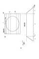
また、ステージ制御部37は、図14に示すように、マクロ画像に基づいて試料Sが占める領域が最大となる分割領域40を第1番目の分割領域として走査してもよい。ここで、各分割領域40において試料Sが占める領域(面積)は、マクロ画像から抽出された試料Sの存在領域と各分割領域40とが重なる領域を特定することにより算出でき、各分割領域40で算出した面積を比較することで、試料Sが占める領域が最大となる分割領域40を特定することができる。
図14に示す例では、ステージ制御部37は、試料Sが占める領域が最大となる分割領域40からステージ1の一方端に向かって各分割領域40を走査する(第1番目~第4番目)。その後、ステージ制御部37は、第1番目に走査した分割領域とステージ1の他方端側に隣接する分割領域40からステージ1の他方端に向かって各分割領域40を走査する(第5番目~第n番目)。このような順に試料Sを走査することで、第1番目の分割領域40の走査時に、他の分割領域40から走査を開始する場合と比較してより多くの焦点制御結果を記憶できる。これにより、以降の分割領域40を走査する際の初期焦点位置を一層精度良く決定できる。なお、試料Sの形状が図14に示すような略楕円形であること等により試料開始位置Pが撮像方向において最も手前に位置する分割領域40と試料Sが占める面積が最大となる分割領域40とが一致することが期待できる場合には、ステージ制御部37は、試料開始位置Pが撮像方向において最も手前に位置する分割領域40を第1番目の分割領域40として走査してもよい。この場合には、各分割領域40における試料Sが占める面積の算出及び比較を行う必要はない。
続いて、上述した画像取得装置Mの動作について説明する。
図15は、画像取得装置Mの動作を示すフローチャートである。同図に示すように、画像取得装置Mでは、まず、マクロ画像取得装置M1による試料Sのマクロ画像の取得がなされる(ステップS1)。取得したマクロ画像は、例えば所定の閾値を用いて二値化された後、モニタ32に表示され、所定のプログラムを用いた自動設定又は操作者による手動設定により、マクロ画像の中からミクロ画像を取得する範囲が設定される(ステップS2)。
次に、ステージ1の走査を開始し、ミクロ画像取得装置M2による試料Sの分割領域40ごとのミクロ画像の取得がなされる(ステップS3)。ステップS3における、第n番目の分割領域の走査開始から第(n+1)番目の分割領域の走査までの処理について、図16を用いて説明する。まず、ステージ1の走査を開始する。第1の撮像装置18でのミクロ画像の取得の際、第2の撮像装置20では第1の撮像領域22A及び第2の撮像領域22Bによって前ピンのコントラスト値と後ピンのコントラスト値の差分に基づいて試料Sに対する対物レンズ15のずれ方向が解析され、対物レンズ15の位置の調整がリアルタイムで実行される。これと併せて、分割領域40を走査する際の焦点制御結果が記憶される(ステップS31)。
続いて、第n番目(nの初期値は1)以前の分割領域40を走査する際に記憶された焦点制御結果に基づいて、第(n+1)番目の分割領域40を走査する際の初期焦点位置が決定される(ステップS32)。その後、決定された初期焦点位置に対物レンズ15の位置が移動され(ステップS33)、第(n+1)番目の分割領域40について、ステップS31と同様の処理が行われる(ステップS34)。全ての分割領域40についてミクロ画像の取得が完了した後、取得されたミクロ画像が合成され、バーチャルマイクロ画像が生成される(ステップS4)。
以上説明したように、画像取得装置Mでは、分割領域40を走査する際に焦点位置の制御結果を記憶し、第(n+1)番目の分割領域を走査する際の初期焦点位置を、第n番目(nは1以上の整数)以前の分割領域40を走査する際に記憶した制御結果に基づいて決定する。このような手法により、この画像取得装置Mでは、すでに走査を完了した分割領域40の焦点制御結果を利用して次に走査する分割領域での初期焦点位置を大まかに求めることが可能となる。これにより、プレフォーカスの簡易化により、撮像に要する処理時間の増大を抑制できる。
上述した実施形態では、バーチャルマイクロ画像を生成する装置を例示したが、本発明に係る画像取得装置は、ステージ等によって試料を所定の速度で走査しながら画像を取得する装置であれば、種々の装置に適用することができる。
1…ステージ、12…光源、14…導光光学系、15…対物レンズ、16…ビームスプリッタ(光分岐手段)、18…第1の撮像装置(第1の撮像手段)、20…第2の撮像装置(第2の撮像手段)、20a…撮像面、21(21A)…光路差生成部材、22A…第1の撮像領域、22B…第2の撮像領域、34…焦点制御部(焦点制御手段)、35…領域制御部(領域制御手段)、36…対物レンズ制御部、L1…第1の光路、L2…第2の光路、M…画像取得装置、M1…マクロ画像取得装置、M2…ミクロ画像取得装置、S…試料。
Claims (12)
- 試料が載置されるステージと、
前記試料に向けて光を照射する光源と、
前記試料の光像を画像取得用の第1の光路及び焦点制御用の第2の光路に分岐する光分岐手段を含む導光光学系と、
前記第1の光路に分岐された第1の光像による第1の画像を取得する第1の撮像手段と、
前記第2の光路に分岐された第2の光像による第2の画像を取得する第2の撮像手段と、
前記第1の撮像手段及び前記第2の撮像手段による前記試料の撮像位置を予め定められた複数の分割領域に沿って走査する走査制御手段と、
前記第2の画像を解析し、その解析結果に基づいて前記第1の撮像手段による撮像の焦点位置を制御する焦点制御手段と、を備え、
前記焦点制御手段は、前記走査制御手段が前記分割領域を走査する際に前記焦点位置の制御結果を記憶し、前記走査制御手段が第(n+1)番目の分割領域を走査する際の初期焦点位置を、前記走査制御手段が第n番目(nは1以上の整数)以前の分割領域を走査する際に記憶した前記制御結果に基づいて決定することを特徴とする画像取得装置。 - 前記焦点制御手段は、前記走査制御手段が第(n+1)番目の分割領域を走査する際の初期焦点位置を、第(n+1)番目の分割領域に隣接する分割領域を走査する際に記憶した前記制御結果に基づいて決定することを特徴とする請求項1記載の画像取得装置。
- 前記焦点制御手段は、第n番目以前の複数の分割領域を走査する際に記憶した前記制御結果に基づいて、前記走査制御手段が第(n+1)番目の分割領域を走査する際の初期焦点位置を決定することを特徴とする請求項1記載の画像取得装置。
- 前記第2の撮像手段の撮像面に、前記第2の光像の一部画像を取得する第1の撮像領域及び第2の撮像領域を設定する領域制御手段と、
前記第2の光路に配置され、前記撮像面の面内方向に沿って前記第2の光像に光路差を生じさせる光路差生成部材と、を更に備え、
前記焦点制御手段は、前記第1の撮像領域で取得した画像のコントラスト値と、前記第2の撮像領域で取得した画像のコントラスト値との差分の絶対値が所定値以下となる走査位置で前記焦点位置の制御結果を記憶することを特徴とする請求項1~3のいずれか一項記載の画像取得装置。 - 前記試料全体を含むマクロ画像を取得するマクロ画像取得手段を更に備え、
前記焦点制御手段は、前記マクロ画像に基づいて前記走査制御手段が前記試料の存在領域を走査している期間中に前記焦点位置の制御結果を記憶することを特徴とする請求項1~4のいずれか一項記載の画像取得装置。 - 前記試料全体を含むマクロ画像を取得するマクロ画像取得手段を更に備え、
前記走査制御手段は、前記マクロ画像に基づいて前記試料が占める領域が最大となる分割領域を第1番目の分割領域として走査することを特徴とする請求項1~5のいずれか一項記載の画像取得装置。 - 試料が載置されるステージと、
前記試料に向けて光を照射する光源と、
前記試料の光像を画像取得用の第1の光路及び焦点制御用の第2の光路に分岐する光分岐手段を含む導光光学系と、
前記第1の光路に分岐された第1の光像による第1の画像を取得する第1の撮像手段と、
前記第2の光路に分岐された第2の光像による第2の画像を取得する第2の撮像手段と、
前記第1の撮像手段及び前記第2の撮像手段による前記試料の撮像位置を予め定められた複数の分割領域に沿って走査する走査制御手段と、
前記第2の画像を解析し、その解析結果に基づいて前記第1の撮像手段による撮像の焦点位置を制御する焦点制御手段と、を備えた画像取得装置のフォーカス方法であって、
前記走査制御手段が前記分割領域を走査する際の前記焦点位置の制御結果を記憶し、
前記走査制御手段が第(n+1)番目の分割領域を走査する際の初期焦点位置を、前記走査制御手段が第n番目(nは1以上の整数)以前の分割領域を走査する際に記憶した前記制御結果に基づいて決定することを特徴とする画像取得装置のフォーカス方法。 - 前記走査制御手段が第(n+1)番目の分割領域を走査する際の初期焦点位置を、第(n+1)番目の分割領域に隣接する分割領域を走査する際に記憶した前記制御結果に基づいて決定することを特徴とする請求項7記載の画像取得装置のフォーカス方法。
- 第n番目以前の複数の分割領域を走査する際に記憶した前記制御結果に基づいて、前記走査制御手段が第(n+1)番目の分割領域を走査する際の初期焦点位置を決定することを特徴とする請求項7記載の画像取得装置のフォーカス方法。
- 前記画像取得装置が、前記第2の撮像手段の撮像面に、前記第2の光像の一部画像を取得する第1の撮像領域及び第2の撮像領域を設定する領域制御手段と、
前記第2の光路に配置され、前記撮像面の面内方向に沿って前記第2の光像に光路差を生じさせる光路差生成部材と、を更に備え、
前記第1の撮像領域で取得した画像のコントラスト値と、前記第2の撮像領域で取得した画像のコントラスト値との差分の絶対値が所定値以下となる走査位置で前記焦点位置の制御結果を記憶することを特徴とする請求項7~9のいずれか一項記載の画像取得装置のフォーカス方法。 - 前記画像取得装置が、前記試料全体を含むマクロ画像を取得するマクロ画像取得手段を更に備え、
前記マクロ画像に基づいて前記走査制御手段が前記試料の存在領域を走査している期間中に前記焦点位置の制御結果を記憶することを特徴とする請求項7~10のいずれか一項記載の画像取得装置のフォーカス方法。 - 前記画像取得装置が、前記試料全体を含むマクロ画像を取得するマクロ画像取得手段を更に備え、
前記走査制御手段によって、前記マクロ画像に基づいて前記試料が占める領域が最大となる分割領域を第1番目の分割領域として走査することを特徴とする請求項7~11のいずれか一項記載の画像取得装置のフォーカス方法。
Priority Applications (3)
| Application Number | Priority Date | Filing Date | Title |
|---|---|---|---|
| US14/439,000 US20150296126A1 (en) | 2012-10-31 | 2013-07-24 | Image capturing apparatus and focusing method thereof |
| EP13851953.3A EP2916160B1 (en) | 2012-10-31 | 2013-07-24 | Image acquisition device and method for focusing image acquisition device |
| CN201380057414.1A CN104769480B (zh) | 2012-10-31 | 2013-07-24 | 图像取得装置和图像取得装置的聚焦方法 |
Applications Claiming Priority (2)
| Application Number | Priority Date | Filing Date | Title |
|---|---|---|---|
| JP2012-240494 | 2012-10-31 | ||
| JP2012240494A JP5941395B2 (ja) | 2012-10-31 | 2012-10-31 | 画像取得装置及び画像取得装置のフォーカス方法 |
Publications (1)
| Publication Number | Publication Date |
|---|---|
| WO2014069053A1 true WO2014069053A1 (ja) | 2014-05-08 |
Family
ID=50626978
Family Applications (1)
| Application Number | Title | Priority Date | Filing Date |
|---|---|---|---|
| PCT/JP2013/070051 WO2014069053A1 (ja) | 2012-10-31 | 2013-07-24 | 画像取得装置及び画像取得装置のフォーカス方法 |
Country Status (5)
| Country | Link |
|---|---|
| US (1) | US20150296126A1 (ja) |
| EP (1) | EP2916160B1 (ja) |
| JP (1) | JP5941395B2 (ja) |
| CN (1) | CN104769480B (ja) |
| WO (1) | WO2014069053A1 (ja) |
Families Citing this family (14)
| Publication number | Priority date | Publication date | Assignee | Title |
|---|---|---|---|---|
| US9971140B2 (en) | 2011-12-19 | 2018-05-15 | Hamamatsu Photonics K.K. | Image capturing apparatus and focusing method thereof |
| WO2014112086A1 (ja) | 2013-01-17 | 2014-07-24 | 浜松ホトニクス株式会社 | 画像取得装置及び画像取得装置のフォーカス方法 |
| EP2947490A4 (en) | 2013-01-17 | 2016-08-31 | Hamamatsu Photonics Kk | IMAGE ACQUISITION DEVICE AND FOCUSING METHOD FOR IMAGE ACQUISITION DEVICE |
| DK3333608T3 (da) | 2013-01-17 | 2021-04-12 | Hamamatsu Photonics Kk | Billedopfangningsanordning og fremgangsmåde til fokusering deraf |
| JP2016051168A (ja) * | 2014-08-29 | 2016-04-11 | キヤノン株式会社 | 画像取得装置およびその制御方法 |
| US10477097B2 (en) | 2017-01-03 | 2019-11-12 | University Of Connecticut | Single-frame autofocusing using multi-LED illumination |
| JP6985506B2 (ja) | 2017-09-29 | 2021-12-22 | ライカ バイオシステムズ イメージング インコーポレイテッドLeica Biosystems Imaging, Inc. | リアルタイムオートフォーカス合焦アルゴリズム |
| US10782515B2 (en) * | 2017-10-24 | 2020-09-22 | Olympus Corporation | Microscope system, observation method, and computer-readable recording medium |
| CN109328455B (zh) * | 2017-12-27 | 2020-10-16 | 深圳配天智能技术研究院有限公司 | 图像获取装置及图像获取方法 |
| CN108387517A (zh) * | 2018-02-26 | 2018-08-10 | 深圳市生强科技有限公司 | 切片扫描方法及系统 |
| CN109272575B (zh) * | 2018-09-28 | 2022-06-28 | 麦克奥迪实业集团有限公司 | 一种提高数字切片扫描仪建模速度的方法 |
| TWI677706B (zh) * | 2018-11-30 | 2019-11-21 | 財團法人金屬工業研究發展中心 | 顯微裝置以及自動對焦方法 |
| GB2595873B (en) * | 2020-06-09 | 2023-01-25 | Ffei Ltd | A method for analysing scanning efficacy |
| CN113358056B (zh) * | 2021-05-31 | 2023-06-27 | 深圳中科飞测科技股份有限公司 | 工件表面形貌的扫描方法、扫描系统及存储介质 |
Citations (4)
| Publication number | Priority date | Publication date | Assignee | Title |
|---|---|---|---|---|
| JP2004514920A (ja) * | 2000-05-03 | 2004-05-20 | ダーク・ソーンクセン | 全自動迅速顕微鏡用スライドスキャナ |
| JP2006189510A (ja) * | 2004-12-28 | 2006-07-20 | Seiko Precision Inc | 顕微鏡装置及び拡大画像生成方法 |
| JP2011081211A (ja) | 2009-10-07 | 2011-04-21 | Olympus Corp | 顕微鏡システム |
| JP2011085652A (ja) * | 2009-10-13 | 2011-04-28 | Olympus Corp | 画像取得装置 |
Family Cites Families (6)
| Publication number | Priority date | Publication date | Assignee | Title |
|---|---|---|---|---|
| IL156500A0 (en) * | 2001-01-05 | 2004-01-04 | Immunivest Corp | Devices and methods to image objects |
| WO2005010495A2 (en) * | 2003-07-22 | 2005-02-03 | Trestle Corporation | System and method for generating digital images of a microscope slide |
| JP2005202092A (ja) * | 2004-01-15 | 2005-07-28 | Hitachi Kokusai Electric Inc | 合焦点検出方法及びそれを用いた光学顕微鏡 |
| JP4917330B2 (ja) * | 2006-03-01 | 2012-04-18 | 浜松ホトニクス株式会社 | 画像取得装置、画像取得方法、及び画像取得プログラム |
| US8878923B2 (en) * | 2007-08-23 | 2014-11-04 | General Electric Company | System and method for enhanced predictive autofocusing |
| JP2010191298A (ja) * | 2009-02-19 | 2010-09-02 | Nikon Corp | 顕微鏡 |
-
2012
- 2012-10-31 JP JP2012240494A patent/JP5941395B2/ja active Active
-
2013
- 2013-07-24 CN CN201380057414.1A patent/CN104769480B/zh active Active
- 2013-07-24 EP EP13851953.3A patent/EP2916160B1/en active Active
- 2013-07-24 US US14/439,000 patent/US20150296126A1/en not_active Abandoned
- 2013-07-24 WO PCT/JP2013/070051 patent/WO2014069053A1/ja active Application Filing
Patent Citations (4)
| Publication number | Priority date | Publication date | Assignee | Title |
|---|---|---|---|---|
| JP2004514920A (ja) * | 2000-05-03 | 2004-05-20 | ダーク・ソーンクセン | 全自動迅速顕微鏡用スライドスキャナ |
| JP2006189510A (ja) * | 2004-12-28 | 2006-07-20 | Seiko Precision Inc | 顕微鏡装置及び拡大画像生成方法 |
| JP2011081211A (ja) | 2009-10-07 | 2011-04-21 | Olympus Corp | 顕微鏡システム |
| JP2011085652A (ja) * | 2009-10-13 | 2011-04-28 | Olympus Corp | 画像取得装置 |
Non-Patent Citations (1)
| Title |
|---|
| See also references of EP2916160A4 |
Also Published As
| Publication number | Publication date |
|---|---|
| EP2916160B1 (en) | 2020-05-27 |
| JP5941395B2 (ja) | 2016-06-29 |
| JP2014089411A (ja) | 2014-05-15 |
| CN104769480A (zh) | 2015-07-08 |
| EP2916160A4 (en) | 2016-06-01 |
| CN104769480B (zh) | 2017-03-29 |
| EP2916160A1 (en) | 2015-09-09 |
| US20150296126A1 (en) | 2015-10-15 |
Similar Documents
| Publication | Publication Date | Title |
|---|---|---|
| JP5941395B2 (ja) | 画像取得装置及び画像取得装置のフォーカス方法 | |
| JP5923026B2 (ja) | 画像取得装置及び画像取得方法 | |
| JP5307221B2 (ja) | 画像取得装置及び画像取得装置のフォーカス方法 | |
| JP2015230393A (ja) | 撮像装置の制御方法および撮像システム | |
| JP5301642B2 (ja) | 画像取得装置及び画像取得装置のフォーカス方法 | |
| JP5848596B2 (ja) | 画像取得装置及び画像取得装置のフォーカス方法 | |
| WO2014112085A1 (ja) | 画像取得装置及び画像取得装置のフォーカス方法 | |
| JP5296861B2 (ja) | 画像取得装置及び画像取得装置のフォーカス方法 | |
| WO2014112084A1 (ja) | 画像取得装置及び画像取得装置のフォーカス方法 | |
| WO2014112086A1 (ja) | 画像取得装置及び画像取得装置のフォーカス方法 | |
| WO2014112083A1 (ja) | 画像取得装置及び画像取得装置のフォーカス方法 | |
| JP2013088570A (ja) | 顕微鏡装置 | |
| JP5986041B2 (ja) | 画像取得装置及び画像取得装置のフォーカス方法 | |
| JP6023012B2 (ja) | 画像取得装置及び画像取得装置のフォーカス方法 | |
| WO2019123869A1 (ja) | 画像取得装置及び画像取得方法 | |
| JP6010506B2 (ja) | 画像取得装置及び画像取得装置のフォーカス方法 |
Legal Events
| Date | Code | Title | Description |
|---|---|---|---|
| 121 | Ep: the epo has been informed by wipo that ep was designated in this application |
Ref document number: 13851953 Country of ref document: EP Kind code of ref document: A1 |
|
| WWE | Wipo information: entry into national phase |
Ref document number: 14439000 Country of ref document: US |
|
| NENP | Non-entry into the national phase |
Ref country code: DE |
|
| WWE | Wipo information: entry into national phase |
Ref document number: 2013851953 Country of ref document: EP |