WO2014069036A1 - 鞍乗り型車両のフレーム構造 - Google Patents
鞍乗り型車両のフレーム構造 Download PDFInfo
- Publication number
- WO2014069036A1 WO2014069036A1 PCT/JP2013/066810 JP2013066810W WO2014069036A1 WO 2014069036 A1 WO2014069036 A1 WO 2014069036A1 JP 2013066810 W JP2013066810 W JP 2013066810W WO 2014069036 A1 WO2014069036 A1 WO 2014069036A1
- Authority
- WO
- WIPO (PCT)
- Prior art keywords
- frame
- frames
- saddle
- suspension
- down frame
- Prior art date
- Legal status (The legal status is an assumption and is not a legal conclusion. Google has not performed a legal analysis and makes no representation as to the accuracy of the status listed.)
- Ceased
Links
Images





Classifications
-
- B—PERFORMING OPERATIONS; TRANSPORTING
- B62—LAND VEHICLES FOR TRAVELLING OTHERWISE THAN ON RAILS
- B62K—CYCLES; CYCLE FRAMES; CYCLE STEERING DEVICES; RIDER-OPERATED TERMINAL CONTROLS SPECIALLY ADAPTED FOR CYCLES; CYCLE AXLE SUSPENSIONS; CYCLE SIDECARS, FORECARS, OR THE LIKE
- B62K11/00—Motorcycles, engine-assisted cycles or motor scooters with one or two wheels
- B62K11/02—Frames
- B62K11/10—Frames characterised by the engine being over or beside driven rear wheel
-
- B—PERFORMING OPERATIONS; TRANSPORTING
- B62—LAND VEHICLES FOR TRAVELLING OTHERWISE THAN ON RAILS
- B62K—CYCLES; CYCLE FRAMES; CYCLE STEERING DEVICES; RIDER-OPERATED TERMINAL CONTROLS SPECIALLY ADAPTED FOR CYCLES; CYCLE AXLE SUSPENSIONS; CYCLE SIDECARS, FORECARS, OR THE LIKE
- B62K19/00—Cycle frames
- B62K19/02—Cycle frames characterised by material or cross-section of frame members
- B62K19/04—Cycle frames characterised by material or cross-section of frame members the material being wholly or mainly metallic, e.g. of high elasticity
- B62K19/10—Combinations of tube and sheet
-
- B—PERFORMING OPERATIONS; TRANSPORTING
- B62—LAND VEHICLES FOR TRAVELLING OTHERWISE THAN ON RAILS
- B62K—CYCLES; CYCLE FRAMES; CYCLE STEERING DEVICES; RIDER-OPERATED TERMINAL CONTROLS SPECIALLY ADAPTED FOR CYCLES; CYCLE AXLE SUSPENSIONS; CYCLE SIDECARS, FORECARS, OR THE LIKE
- B62K2202/00—Motorised scooters
Definitions
- the present invention relates to a frame structure of a saddle-ride type vehicle including a head pipe, a down frame extending downward from a rear portion of the head pipe, and a lower frame extending rearward from a lower portion of the down frame.
- a frame structure of a saddle-ride type vehicle in which a frame constituted by a leg shield, a lower frame, or the like that supports a head pipe is formed by combining a plurality of plate materials (see, for example, Patent Document 1). ).
- the frame which becomes the vehicle body skeleton is composed entirely of plate material, and generally used pipe material is not used.
- the required characteristics differ depending on the part. Therefore, by making the frame structure taking advantage of the plate material and pipe material, weight reduction is achieved while improving the function of the frame. It is desirable.
- the present invention has been made in view of the above-described circumstances, and an object of the present invention is to make it possible to reduce the weight while improving the function of the frame in the frame structure of the saddle-ride type vehicle.
- the present invention comprises a head pipe (11) for pivotally supporting a front wheel (2), a down frame (12) extending downward from a rear portion of the head pipe (11),
- the down frame (12) is made of a pipe material
- the lower frame ( 13) are provided in a pair of left and right, and each has a closed cross section made of a plate material having a vertically divided structure, and the lower frame (13) extends in the vehicle width direction from the connecting portion with the down frame (12).
- a bent portion (64) bent rearward bent rearward.
- the down frame is composed of a pipe material, so that the rigidity and strength required for the down frame can be secured while reducing the number of connecting portions of the down frame, and the lower frame is a closed cross section made of a plate material having an upper and lower split structure. Therefore, the cross-sectional area and shape of the bent portion can be optimized to disperse the stress acting on the bent portion, and the weight can be reduced. For this reason, weight reduction can be achieved, ensuring the strength and rigidity required for the frame.
- the lower frame (13) includes an upper lower frame (70) and a lower lower frame (71) to form a two-part structure, and the lower frame (13)
- the shape change is characterized in that the lower upper frame (70) is formed to be larger than the lower down frame (71).
- the present invention since the shape change of the lower frame is formed so that the lower upper frame is larger than the lower down frame, the input load from the down frame is gently transmitted via the lower upper frame. It is possible to avoid stress concentration and optimize strength and rigidity.
- the present invention is characterized in that the upper surface of the lower upper frame (70) is formed so as to be positioned gradually upward on the down frame (12) side.
- the lower upper frame when the lower down frame is viewed as a fulcrum for supporting the down frame, the lower upper frame is connected at a position close to the head pipe, which is the load input point, and the lower upper frame has a gently cross-sectional shape. It will change, and it can control that stress concentration arises by the input load from a head pipe. For this reason, a load can be disperse
- the lower frame (13) includes a straight portion (65) extending in the front-rear direction behind the bent portion (64), and the bent portion (64), the straight portion (65), and The cross-sectional area is minimized at the boundary position (X).
- the rigidity does not suddenly increase at the boundary position between the straight portion and the bent portion having high rigidity, the rigidity characteristic of the lower frame as a whole can be moderated, and the weight can be further reduced.
- the present invention is characterized in that the lower upper frame (70) has a height (H1) behind the bent portion (64) smaller than a height (H2) of the lower down frame. According to the present invention, even in a lower upper frame having a large shape change, moldability can be ensured and productivity can be improved.
- the lower upper frame (70) is overlapped with the lower down frame (71) from the outside and is mutually connected to the lower down frame (71) at a lower edge of the lower upper frame (70). It is fixed by welding. According to the present invention, the stress concentration applied to the welded portion can be suppressed by providing the welded portion at the intermediate portion in the height direction of the lower frame. For this reason, further weight reduction can be achieved.
- the pair of left and right lower frames (13) are welded so as to surround the lower portion of the down frame (12) in a semicircular shape when viewed from above, and the front of the down frame (12) is provided.
- the front connecting portion (82) and the rear connecting portion (83) at the front ends of the pair of left and right lower frames (13) are in contact with each other and welded.
- the welding length can be increased by surrounding the lower part of the down frame in a semicircular shape, and the welding strength can be improved by welding the front connecting part and the rear connecting part.
- the rigidity of the lower part of a down frame can be improved by enclosing the lower part of a down frame with a lower frame.
- a notch (a predetermined size) is provided between the abutting portions of the pair of left and right lower frames (13) of the front connecting portion (82) and / or the rear connecting portion (83). 75), and the lower frame (13) is welded to the down frame (12) through the notch (75).
- the left and right lower frames and the down frame can be welded through the notches, and the joint strength can be improved.
- the frame structure of the saddle-ride type vehicle it is possible to reduce the weight while securing the strength and rigidity necessary for the frame.
- the input load from the down frame can be gently transmitted via the lower upper frame, so that stress concentration can be avoided and optimization of strength and rigidity can be achieved.
- the rigidity does not suddenly increase at the boundary position between the straight portion and the bent portion having high rigidity, the rigidity characteristic of the lower frame as a whole can be moderated, and the weight can be further reduced.
- the moldability can be secured and the productivity can be improved.
- the welded portion can be provided in the intermediate portion in the height direction of the lower frame to suppress stress concentration applied to the welded portion, and further weight reduction can be achieved.
- the welding length can be increased by surrounding the lower portion of the down frame in a semicircular shape, and the welding strength can be improved by welding the front connecting portion and the rear connecting portion.
- the rigidity of the lower part of a down frame can be improved.
- the left and right lower frames and the down frame can be welded through the notches, and the joint strength can be improved.
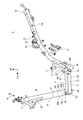
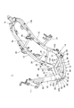
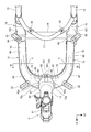
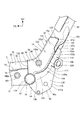
- FIG. 1 is a left side view of a motorcycle according to a first embodiment of the present invention. It is a left view of a vehicle body frame. It is a perspective view of a body frame. It is the top view which looked at the front part of the body frame from the upper part. It is the figure which looked at the lower part of the body frame from the front.
- FIG. 6 is a sectional view taken along line VI-VI in FIG. 4. It is a perspective view of a lower upper frame. It is the perspective view which looked at the suspension part vicinity from the back side. It is the figure which looked at the suspension part from back. It is the side view which looked at the suspension part of the left side from the vehicle width direction outer side.
- FIG. 1 is a left side view of a motorcycle according to a first embodiment of the present invention.
- the motorcycle 1 (saddle-ride type vehicle) is a scooter type vehicle having a low floor step floor 52 on which a rider seated on a seat 10 places his / her foot, and has a front wheel 2 in front of a body frame F, A certain rear wheel 3 is pivotally supported by a unit swing engine U (unit swing power unit) disposed at the rear of the vehicle.
- the vehicle body frame F is covered with a resin vehicle body cover C.
- FIG. 2 is a left side view of the vehicle body frame F.
- FIG. FIG. 3 is a perspective view of the vehicle body frame F.
- FIG. FIG. 4 is a plan view of the front portion of the vehicle body frame F as viewed from above.
- the vehicle body frame F is formed by connecting a plurality of metal pipes and plate materials by welding, and includes a head pipe 11 provided at the front part and a rear part from the rear part of the head pipe 11.
- Down frame 12 extending downward, a pair of left and right lower frames 13 and 13 extending in the vehicle width direction from the lower part of down frame 12 and then bending and extending rearward, and the rear ends of lower frames 13 and 13
- a pair of left and right suspension parts 14, 14 connected to each other and a pair of left and right rear frames 15, 15 extending from the rear end of the suspension parts 14, 14 rearward and upward to the rear part of the vehicle are provided.
- the body frame F is a cross frame that connects the left and right frames, and a cross member 16 that connects the rear portions of the lower frames 13 and 13 and a front portion of the rear frames 15 and 15 that is above the cross member 16.
- An intermediate cross member 17, a rear cross member 18 that connects the front and rear intermediate portions of the rear frames 15, 15, and a rear end cross member 19 that connects the rear ends of the rear frames 15, 15 are provided.
- the head pipe 11 is reinforced by the reinforcing plate 20 with the lower part of the rear part connected to the upper part of the down frame 12.
- a pair of left and right step stays 21, 21 extending rearward and downward are provided behind the intermediate cross member 17.
- Stays 22 and 22 are provided at the front and rear portions of the upper surfaces of the lower frames 13 and 13 so as to protrude upward in the vehicle width direction.
- a pipe-like step frame (not shown) is disposed between the front and rear stays 22, 22.
- a side stand 39 is attached to the rear portion of the left lower frame 13.
- the steering system for steering the front wheels 2 includes a steering shaft (not shown) pivotally supported by the head pipe 11, a handle 25 coupled to the upper portion of the steering shaft, A pair of left and right front forks 26, 26 are connected to the lower end of the steering shaft.
- the front wheel 2 is pivotally supported at the lower ends of the front forks 26 and 26 and is steered by an operation with the handle 25.
- the unit swing engine U is a unit swing type in which an engine E and a transmission case M in which a belt-type continuously variable transmission mechanism (not shown) is accommodated, and is used as a swing arm that supports the rear wheel 3. It also has a function.
- the unit swing engine U is indirectly connected to the suspension parts 14 and 14 via a link member 27 connected to the front part thereof, and swings up and down around a pivot shaft 28 provided on the link member 27. It is free.
- the engine E is a water-cooled four-cycle single-cylinder engine, and is arranged so that the cylinder axis 29 extends substantially horizontally forward.
- the engine E is configured by connecting a cylinder 31 and a cylinder head 32 to the front surface of a crankcase 30 disposed at the front of the unit swing engine U.
- the transmission case M extends rearward from the rear portion of the crankcase 30 through the left side of the rear wheel 3.
- the rear wheel 3 is supported by an axle 3 a provided at the rear part of the transmission case M.
- the output of the engine E is transmitted to the rear wheel 3 through the continuously variable transmission mechanism.
- a rear cushion member 33 is disposed between the rear end of the transmission case M and the left rear frame 15 so as to be inclined forward.
- an air cleaner box 34 for sucking outside air is provided on the upper surface of the transmission case M.
- the air cleaner box 34 is connected to a throttle body 35 connected to an intake port on the upper surface of the cylinder head 32.
- An exhaust pipe 36 connected to an exhaust port on the lower surface of the cylinder head 32 extends rearward under the engine E and is connected to a muffler 37 provided on the right side of the rear wheel 3.
- a fuel tank 40 that stores fuel for the engine E is disposed between the lower frames 13 and 13 and in front of the cross member 16 at the rear of the down frame 12.
- the fuel tank 40 is disposed such that the front surface is along the down frame 12 and the bottom surface is along the lower frames 13 and 13, and the rear surface is inclined forward.
- a storage box 41 for storing articles is disposed between the rear frames 15 and 15 and extends from the vicinity of the rear portion of the fuel tank 40 to above the transmission case M.
- the storage box 41 is connected to the intermediate cross member 17, the rear cross member 18, and a plurality of stays 38 provided on the upper surfaces of the rear frames 15 and 15.
- the upper surface of the storage box 41 is opened above the rear frames 15, 15 over the entire length thereof, and the opening is closed by an occupant seat 10 so as to be freely opened and closed.
- the seat 10 includes a front seat 10a on which a driver is seated and a rear seat 10b that is formed one step higher than the front seat 10a and on which a passenger sits.
- a grab rail 42 is fixed to the rear of the rear frames 15 and 15 behind the storage box 41.
- the vehicle body cover C is continuously provided on the front cover 45 that covers the head pipe 11 and the down frame 12 from the front and side, the upper inner cover 46 that covers the head pipe 11 from the rear, and the lower part of the upper inner cover 46.
- a lower inner cover 47 that covers the fuel tank 40 from above, a rear cover 48 that covers the storage box 41 and the rear frames 15 and 15 from the side, and a front cover 45 and a rear cover 48 are arranged continuously below the fuel tank 40 and
- a middle cover 49 that covers the front portions of the rear frames 15 and 15 from the side and a lower cover 50 that covers the lower portion of the vehicle body frame F from below and from the sides are provided.
- a screen 44 extending rearward and upward is provided on the upper portion of the front cover 45.
- the lower inner cover 47, the rear part of the front cover 45, and the middle cover 49 form a center tunnel part 51 that bulges upward between both feet of the driver seated on the seat 10, and the lower edge of the center tunnel part 51
- the driver places his / her feet on a pair of left and right step floors 52 extending outward in the vehicle width direction.
- the step floor 52 is supported from below by the step frame.
- the step floor 52 extends rearward to the vicinity of the unit swing engine U, and a tandem step 52a on which a passenger puts his / her foot is provided at the rear end of the step floor 52.
- Each tandem step 52a is supported by step stays 21, 21 (FIG. 2).
- the front wheel 2 is covered from above by a front fender 53.
- the rear wheel 3 is covered from above by the rear fender 54.
- the down frame 12 is a pipe-shaped frame, and is connected to the head pipe 11 and has an upper pipe portion 60 that extends downward to an upper and lower middle portion with a substantially constant diameter, and an upper pipe.
- a tapered portion 61 that extends downward from the portion 60 and has a large diameter portion 62 that is formed to have a larger diameter than the upper pipe portion 60 and extends from the tapered portion 61 to the lower end of the down frame 12 with substantially the same diameter. ing.
- the large-diameter portion 62 has an oval cross-sectional shape that is long in the vehicle width direction, and an outer peripheral portion thereof includes a pair of left and right curved surface portions 62a and 62a having a semicircular cross section and curved surface portions 62a and 62a.
- Each lower frame 13 includes a front end coupling portion 63 coupled to the large-diameter portion 62 of the down frame 12, a bent portion 64 that bends rearward after extending outward in the vehicle width direction from the front end coupling portion 63, and a bent portion.
- a straight portion 65 linearly extending in the front-rear direction substantially horizontally from 64 to the rear end of the lower frame 13, and a rear end coupling portion 66 coupled to the suspension portion 14 at the rear end of the straight portion 65.
- the suspension portion 14 is coupled to the rear end coupling portion 66, the rear frame 15 is coupled to the rear end of the suspension portion 14, and the rear frame 15 is fixed by the suspension portion 14 in a direction directed rearward and upward. Extends upward.
- the suspension portion 14 is a bent part that bends the vehicle body frame F.
- the suspension portion 14 is provided between the lower frame 13 and the rear frame 15, it can be said that the suspension portion 14 is provided at the rear end of the lower frame 13.
- a mounting portion 15 b to which the upper end of the rear cushion member 33 is connected is provided at the rear portion of the left (one side) rear frame 15. No rear cushion member is arranged on the right side (the other side).
- FIG. 5 is a view of the lower part of the body frame F as viewed from the front.
- 6 is a sectional view taken along line VI-VI in FIG.
- the lower frames 13 and 13 are divided into two parts in the vertical direction, and are formed by connecting a lower upper frame 70 constituting the upper half and a lower down frame 71 constituting the lower half.
- the lower upper frame 70 is formed in a bowl shape that opens downward
- the lower down frame 71 is formed in a bowl shape that opens upward.
- each lower frame 13 is formed in a hollow pipe shape.
- the lower upper frame 70 and the lower down frame 71 are manufactured by forming a plate material by press working using a mold, the degree of freedom of the shape is high compared with the case of forming a pipe material, and the lower upper frame 70 and the lower down frame 71 are pressed.
- a pipe shape having a continuously changing cross-sectional shape can be easily formed even if the shape has the bent portion 64.
- FIG. 7 is a perspective view of the lower upper frame 70.
- the bent portion 64 of the lower frame 13 is formed by continuously changing its shape so as to become wider as it approaches the large diameter portion 62 of the down frame 12. That is, the lower upper frame 70 and the lower down frame 71 are formed so as to be wider toward the front end coupling portion 63 side.
- the upper surface of the lower upper frame 70 has a bulging portion 72 that gradually increases from the outside in the vehicle width direction toward the large diameter portion 62 side.
- a mountain-shaped bulging portion 72 a is formed at the end of the bulging portion 72 on the large-diameter portion 62 side so that the central portion in the width direction of the lower upper frame 70 bulges upward.
- the bottom side of the lower down frame 71 does not have a complicated shape such as a gradual change in height, and extends substantially flat toward the large diameter portion 62. That is, the processing degree on the upper surface side of the lower upper frame 70 is higher than the processing degree on the bottom surface side of the lower down frame 71.
- FIG. 6 is a cross section at the boundary position X between the bent portion 64 and the straight portion 65.
- the height H1 (depth of pressing) of the lower upper frame 70 is lower.
- the down frame 71 is formed lower than the height H2 (depth of press work).
- the height H ⁇ b> 1 of the lower upper frame 70 is lower than the height H ⁇ b> 2 of the lower down frame 71 also in a portion ahead of the boundary position X. That is, the lower upper frame 70 is set to be shallower than the lower down frame 71 in the press molding.
- engagement step portions 73, 73 are formed on the inner sides of the left and right lower edge portions of the bowl shape of the lower upper frame 70, with the lower edge portion bulging outward.
- the engagement step portions 73 and 73 are provided over the entire length of the lower upper frame 70 excluding the front end coupling portion 63 and the rear end coupling portion 66.
- the lower upper frame 70 is provided so that the engagement step portions 73 and 73 are engaged with the left and right upper edge portions of the lower down frame 71 from the outside, and in this state, the front end portions of the engagement step portions 73 and 73 are arranged.
- the lower upper frame 70 and the lower down frame 71 are joined by fillet welding to the lower down frame 71 by the weld bead 74 formed along the engagement step portion 73.
- the pipe-like lower frame 13 which has a closed cross section is formed, respectively.
- the lower upper frame 70 having a lower height is pressed in order to overlap the lower upper frame 70 having a lower height on the lower down frame 71 from the outside and weld it at the lower edge of the lower upper frame 70.
- the weld bead 74 can be moved downward and provided closer to the center of the lower frame 13 in the vertical direction, and stress concentration applied to the weld bead 74 can be suppressed.
- the front end coupling portion 63 of the lower frame 13 is an open end, and the open end of this pipe-shaped member is fitted to the large diameter portion 62 and welded,
- the lower frame 13 is fixed to the down frame 12.
- the front end coupling portion 63 is formed by being cut out in a semicircular shape when viewed from above (FIG. 4) along the outer peripheral portion of the large diameter portion 62, and is formed along the curved surface portion 62 a.
- An upper contact portion 80 and a lower contact portion 81, a front connection portion 82 extending along the curved surface portion 62a of the large diameter portion 62 and the flat surface 62b on the front surface side, and the curved surface portion 62a.
- the upper abutting portion 80 is formed at the front bulged portion 72 a of the lower upper frame 70, and the lower abutting portion 81 is formed at the front end of the lower down frame 71.
- the front connecting portion 82 and the rear connecting portion 83 are formed by joining the tongue portions 70a and 71a formed at the front ends of the lower upper frame 70 and the lower down frame 71, respectively.
- the tongue portions 70 a and 71 a are joined by a weld bead 74.
- Each lower frame 13 has an upper edge and a lower edge of the mountain-shaped bulging portion 72a, the lower abutting portion 81, and the front connecting portion 82 in a state where the front end coupling portion 63 is fitted to the large diameter portion 62 from the side. And welded to the down frame 12 by a weld bead 84 (FIG. 5).
- a weld bead 84 (FIG. 5).
- the front connecting portions 82 and the rear connecting portions 83 of the left and right lower frames 13, 13 contact each other at a position overlapping the axis L of the down frame 12 in the front view and the rear view. They are welded by welding beads 85 (FIG. 5) formed on the contact surfaces 82a and 82a at the front ends and the contact surfaces 83a and 83a.
- the rear connection part 83 on the rear surface side is provided to be offset upward from the front connection part 82 on the front surface side. Since the contact surfaces 82a and 82a and the contact surfaces 83a and 83a are contacted and welded, the strength and rigidity in the vicinity of the front end coupling portion 63 can be improved. Further, since the large diameter portion 62 is surrounded by the front end coupling portion 63 from the entire circumference, the strength and rigidity of the large diameter portion 62 can be improved.
- a notch 75 having a predetermined size is formed in each of the upper and lower intermediate portions of the contact surfaces 82a and 82a and the contact surfaces 83a and 83a.
- the notch 75 is provided with a filler (not shown) such as a filler wire, and the front connecting part 82 and the rear connecting part 83 are welded together by a weld bead 86 provided in the notch 75 together with the filler. And is also welded to the front surface of the down frame 12. For this reason, joint strength can be improved.
- the predetermined size of the notch 75 is set to such a size that the filler can be provided and sufficient welding strength can be obtained.
- the lower frames 13 and 13 are formed by welding the lower upper frame 70 and the lower down frame 71 with the weld beads 74.
- the lower frames 13 and 13 are fitted to the down frame 12, the weld beads 84 formed respectively on the upper and lower sides are welded, the weld bead 85 is welded, and finally the notch 75 together with the filler is formed.
- Each stay 22 is welded after press molding of the lower upper frame 70.
- a force R (FIG. 2) directed in the axial direction of the head pipe 11 is greatly exerted on the front wheel 2 side due to the unevenness of the road surface and acceleration / deceleration, while the force acting in the vehicle width direction is It tends to be smaller than the force R.
- the down frame 12 is provided at the center in the vehicle width direction and is connected to the front wheel 2 side, the down frame 12 is set to receive the force R more efficiently than the force acting in the vehicle width direction.
- the down frame 12 is supported by the front end coupling parts 63 and 63 of the lower frames 13 and 13 at the fulcrum, it is effective to increase the strength and rigidity of the lower part near the fulcrum.
- strength and rigidity are ensured by providing the tapered portion 61 and the large diameter portion 62.
- the down frame 12 only needs to be able to receive force in the vertical and longitudinal directions due to the force R, so that the required strength and rigidity can be obtained by making it simple such as the tapered portion 61 and the large diameter portion 62. can get. For this reason, the optimal shape which satisfy
- the bent portion 64 of the lower frame 13 is located outside the vehicle width direction and is a bent portion, the direction in which the force acts is complicated. For this reason, the optimum shape of the cross section that can obtain the strength and rigidity required in the bent portion 64 becomes complicated, and when the pipe material is processed to obtain the same characteristics as the optimum shape, the plate thickness is It becomes thick and the weight increases.
- the lower frame 13 has a vertically divided structure, and the lower upper frame 70 and the lower down frame 71 having a shape in which the cross-sectional area and shape of the bent portion 64 are optimized are individually formed by press work, Then, since it was welded and formed into a pipe shape with a closed cross section, the optimally shaped lower frame 13 can be easily formed. By adopting the optimal shape, strength and rigidity can be ensured even with a small plate thickness, so that weight reduction can be achieved. By adopting a configuration in which the lower frames 13 and 13 and the down frame 12 are coupled, an optimally shaped frame structure can be easily formed.
- the upper surface of the lower upper frame 70 has a bulging portion 72 that gradually increases as it approaches the large diameter portion 62 side, and the bulging portion 72 joins the lower upper frame 70 to the down frame 12.
- the position can be increased to improve the support strength of the down frame 12, and the input load from the down frame 12 can be transmitted gently. For this reason, stress concentration can be avoided and optimization of strength and rigidity can be achieved.
- the cross-sectional shape of the linear part 65 of the lower frame 13 is formed in an ellipse long vertically. For this reason, the rigidity with respect to the force R is high, and the ride comfort is good. Further, the cross-sectional area of the lower frame 13 is the smallest at the boundary position X (FIG. 4) between the bent portion 64 and the straight portion 65, and gradually increases toward the rear side. For this reason, the rigidity does not suddenly increase at the boundary position X between the straight portion 65 and the bent portion 64 having high rigidity, and the rigidity characteristics of the lower frame 13 as a whole can be moderated.
- FIG. 8 is a perspective view of the vicinity of the suspension portions 14 and 14 as viewed from the rear side.
- plate-like extension portions 90, 90 extending rearward and downward are formed on the rear surfaces of the suspension portions 14, 14, and the link member 27 includes left and right extension portions 90. , 90.
- the link member 27 includes a connecting shaft 91 that is provided between the extending portions 90 and 90 and extends in the vehicle width direction, a pair of arm portions 92 and 92 that extend rearward from the rear surface of the connecting shaft 91, and arm portions 92 and 92.
- a pivot support portion 93 that is fixed to the rear end and extends parallel to the connecting shaft 91 and a stopper 94 that extends forward from the front surface of the connecting shaft 91 are provided.
- the extension portions 90, 90 are provided with shafts (not shown) penetrating the extension portions 90, 90 in the vehicle width direction, and the link member 27 is supported by the connection shaft 91 being pivotally supported by the shaft. It is supported so as to be swingable about an axis.
- the stopper 94 extends to above the cross member 16 and abuts on the upper surface of the cross member 16 via an elastic member (not shown) provided on the lower surface of the stopper 94. That is, the rotation of the link member 27 is regulated by the stopper 94, and the link member 27 can be slightly rotated by the amount of elastic deformation of the elastic member.
- the unit swing engine U is supported by a pivot shaft 28 (FIG. 1) inserted through the pivot support portion 93 and can swing around the pivot shaft 28.
- FIG. 9 is a view of the suspension portions 14 as viewed from the rear.
- FIG. 10 is a side view of the left suspension 14 as viewed from the outside in the vehicle width direction.
- FIG. 11 is a side view of the left suspension 14 as viewed from the inside in the vehicle width direction. Since the left and right suspension parts 14 are formed substantially symmetrically, the description will be made mainly with reference to the left suspension part 14 here.
- the suspension portion 14 includes a front coupling portion 95 coupled to the rear end coupling portion 66 of the lower frame 13, and extends backward from the front coupling portion 95 and then bends.
- a suspension bending portion 96 extending rearward and upward, a rear coupling portion 97 coupled to the front end 15a of the rear frame 15, and the extending portion 90 are provided.
- a pipe fitting portion 98 that opens in a semicircular shape when viewed from the side is formed.
- the pipe fitting portion 98 is fitted to the cross member 16 by welding to the rear half portion of the cross member 16 from the rear.
- a pipe fitting portion 67 that opens in a semicircular shape in a side view is formed at the rear end of the rear end coupling portion 66 of the lower frame 13, and the front half of the cross member 16 is a pipe fitting portion 67. Are welded and fixed to the pipe fitting portion 67.
- a pipe support hole 99 that penetrates the suspension part bending part 96 in the vehicle width direction is formed in the suspension part bending part 96.
- a cylindrical collar 100a (cross member) into which a bolt (not shown) for fixing the side stand 39 to the vehicle body frame F is inserted is fixed to the pipe support hole 99 by welding.
- a pipe support hole 101 that penetrates the lower frame 13 in the vehicle width direction is formed in the rear portion of the left lower frame 13, and the collar 100b extends in the vehicle width direction in the pipe support hole 101. It is welded and fixed in the penetrating state.
- the side stand 39 is fixed by the bolt inserted through the pair of collars 100a and 100b.
- the collars 100a and 100b act as cross members that connect the left and right wall portions of the suspension bending portion 96 and the lower frame 13, respectively, the strength and rigidity of the suspension bending portion 96 and the lower frame 13 can be improved.
- Cutout portions 102, 102 extending in the vertical direction are formed at the front and rear central portions of the rear coupling portion 97.
- the notches 102 are provided on the outer surface side and the inner surface side in the vehicle width direction.
- Each of the extending portions 90 includes an extending portion upper portion 110 that is disposed substantially at the center in the vehicle width direction of the rear frame 15 at a position that overlaps the axis K (FIG. 9) of the rear frame 15 in the rear view, and an extending portion upper portion 110.
- the bent portion 111 is bent inward in the vehicle width direction from the lower end of the extended portion and extends downward in the vehicle width direction, and is located on the inner side of the extended portion bent portion 111 from the lower end of the extended portion bent portion 111 to the axis K.
- an extending portion lower portion 112 extending along the same.
- a support portion 112a (FIG.
- the unit swing engine U is supported between the support portions 112 a and 112 a of the left and right extending portions 90 and 90 via the link member 27.
- the extended lower portions 112 and 112 extend below the cross member 16.
- the suspension portion 14 is formed in a bent pipe shape, and is manufactured by combining plate members that are divided into three in the circumferential direction. Specifically, the suspension portion 14 constitutes the upper surface of the suspension portion 14 and opens to the lower side, and a lower outer member 104 that is divided in the vehicle width direction and constitutes the lower surface of the suspension portion 14. And the lower inner member 105. Since the upper half body 103, the lower outer member 104, and the lower inner member 105 are manufactured by molding a plate material by press working using a mold, the degree of freedom of shape is higher than when a pipe material is molded. By joining the press products, even if the shape is provided with the suspended portion bending portion 96, a pipe-shaped member having a desired cross-sectional shape can be easily formed.
- FIG. 12 is a left side view of the upper half 103.
- FIG. 13 is a left side view of the lower inner member 105.
- FIG. 14 is a cross-sectional view when the vicinity of the suspension 14 is viewed from the side.
- upper half body 103 is formed in a bowl shape, and has a curved upper surface portion 103a, a pair of left and right outer wall portions 103b and inner wall portion 103c extending downward from upper surface portion 103a. And have.
- the upper half 103 is bent so as to warp opposite to the open side of the bowl shape in a side view.
- a front coupling portion 95 is formed at the front end of the upper half 103.
- the front coupling portion 95 is formed in a semicircular shape when viewed from the front, and has a front overlapping portion 95a (FIG. 14) that overlaps and fits on the outer peripheral surface of the upper portion of the rear end coupling portion 66 from the outside. Moreover, the upper half part of the pipe fitting part 98 is formed under the front part overlap part 95a.
- a rear overlapping portion 97 a that forms the front half of the rear coupling portion 97 is formed.
- the rear overlapping portion 97a overlaps the outer peripheral surface of the front surface of the front end 15a of the rear frame 15 from the outside.
- the rear overlapping portion 97a extends to a position where the upper end portion 97d located on the outer side in the vehicle width direction is higher than the inner portion.
- the notch 102 is formed by notching the rear edge of the rear overlapping portion 97a.
- Engagement step portions 106 and 106 (FIG. 12) are formed on the lower edge portions of the outer wall portion 103b and the inner wall portion 103c of the upper half body 103, and the lower edge portion bulges outward.
- the engagement step portions 106 and 106 extend between the pipe fitting portion 98 and the notch portion 102.
- the pipe support hole 99 is provided through the outer wall portion 103b and the inner wall portion 103c.
- the lower inner member 105 (FIG. 13) includes an inner curved surface portion 115 that constitutes an inner portion in the vehicle width direction on the lower surface side of the pipe-like suspension portion 14, and an inner extension portion 116 that constitutes the inner surface of the extension portion 90. And have.
- the cross-sectional shape of the suspension portion 14 in the inner curved surface portion 115 as viewed in the axial direction is formed in a curved surface shape so as to constitute a part of a substantially circular pipe shape.
- a rear overlapping portion 97b constituting the rear portion of the rear coupling portion 97 is formed.
- the lower inner member 105 has an upper extension portion 117 that extends upward from the rear overlapping portion 97b along the rear surface portion of the rear frame 15. At the front edge of the inner curved surface portion 115, an engagement edge portion 115a that is engaged and welded to the engagement step portion 106 of the inner wall portion 103c of the upper half 103 is formed.
- a pipe fitting portion 98 is formed at the front end of the lower inner member 105 so as to straddle the inner curved surface portion 115 and the inner extending portion 116. That is, the upper part of the pipe fitting part 98 on the inner side in the vehicle width direction is provided at the front end of the inner curved surface part 115, and the lower part of the pipe fitting part 98 is provided at the front end of the inner extension part 116.
- a protruding piece 118 that protrudes rearward is formed at a portion corresponding to the extended portion bent portion 111 of the inner extended portion 116.
- a welding portion 119 welded to the lower outer member 104 is provided above the protruding piece 118 at the rear edge of the inner curved surface portion 115.
- a welding portion 120 welded to the lower outer member 104 is provided below the protruding piece 118 at the rear edge of the inner extension portion 116.
- the protruding piece 118 is not welded to the lower outer member 104, but is fixed by welding of adjacent welded portions 119 and 120.
- the welded portion 120 and the pipe fitting portion 98 at the rear and lower edges of the lower inner member 105 are also non-welded portions 121 (FIG. 11) that are not welded to the lower outer member 104.
- the lower outer member 104 (FIG. 10) includes an outer curved surface portion 125 that constitutes an outer portion in the vehicle width direction on the lower surface side of the pipe-like suspension portion 14, and an outer extension portion 126 that constitutes an outer surface of the extension portion 90. And have.
- the cross-sectional shape of the suspension portion 14 in the outer curved surface portion 125 as viewed in the axial direction is formed in a curved surface shape so as to constitute a part of a substantially circular pipe shape.
- a rear overlapping portion 97 c constituting the rear portion of the rear coupling portion 97 is formed at the upper end of the inner curved surface portion 115.
- an engagement edge portion 125a that is engaged and welded to the engagement step portion 106 of the outer wall portion 103b of the upper half 103 is formed.
- the protruding piece 118 (FIG. 11) of the inner extending portion 116 is not welded to the outer extending portion 126.
- the extended portion bent portion 111 is a bent portion, and it is difficult to properly contact the inner extended portion 116 and the outer extended portion 126 depending on the accuracy of press molding. For this reason, in this 1st form, in the extension part bending part 111, it is set as the structure which provides the clearance gap between the inner side extension part 116 and the outer side extension part 126, and welds to this part.
- a protruding piece 118 is provided as a mark indicating a portion not to be used. For this reason, it is easy to perform welding work. The joint strength is sufficiently ensured by the welded portions 119 and 120.
- a pipe fitting portion 98 (FIG. 10) is formed at the front end of the lower outer member 104 across the outer curved surface portion 125 and the outer extension portion 126. That is, the upper part of the pipe fitting part 98 on the outer side in the vehicle width direction is provided at the front end of the outer curved surface part 125, and the lower part of the pipe fitting part 98 is provided at the front end of the outer extension part 126.
- the extension part 90 is formed by joining the outer extension part 126 and the inner extension part 116.
- the outer extension portion 126 is formed larger than the inner extension portion 116 as a whole in a side view, and covers the inner extension portion 116 from the outside.
- Each suspension portion 14 is formed along the engagement step portions 106 and 106 while joining the lower outer member 104 and the lower inner member 105 by weld beads 128 (FIG. 11) formed in the weld portions 119 and 120.
- weld beads 128 FIG. 11
- the pipe is formed.
- each suspension portion 14 is joined to the rear frame 15 by inserting the front end 15a of each rear frame 15 into the rear joint portion 97 and welding in this state.
- the suspension portion 14 includes a weld bead 130 along the upper edge of the rear overlap portion 97 a of the upper half 103, and a weld bead 131 along the rear overlap portion 97 b and the upper extension portion 117 of the lower inner member 105. And a weld bead 132 (FIG. 10) along the edge of the rear overlapping portion 97 c of the lower outer member 104 and joined to the rear frame 15.
- the small assembly 133 in which the suspension part 14 and the rear frame 15 are integrally joined is formed.
- the suspension portion 14 is welded to the rear frame 15 after the suspension portion 14 is formed in a pipe shape.
- the present invention is not limited to this, and the upper half 103 so as to surround the front end 15 a of the rear frame 15.
- the weld bead 130, 131, 132 may be formed in the process of setting the lower outer member 104 and the lower inner member 105 and then forming the weld beads 129, 129.
- the weld beads 130, 131, 132 are also formed at the edges of the outer and inner cutouts 102, 102, and the weld length is longer than that of the configuration in which the cutouts 102, 102 are not provided. Yes. For this reason, joint strength can be improved. In addition, by providing the notches 102 and 102, it becomes easy to deform the portions in the vicinity of the weld beads 130, 131, and 132 along the weld, so that the adhesion of the weld can be improved and the joint strength is improved. it can.
- the cross member 16 is previously joined to the pipe fitting portion 67 at the rear end of the lower frames 13 and 13 by a weld bead 134 (FIG. 10).
- the small assembly 133 is fitted to the rear end coupling portion 66 of the lower frame 13 so that the pipe fitting portion 98 at the front end of the suspension portion 14 is brought into contact with the cross member 16 from the rear, and the front edge of the front overlapping portion 95a is fitted.
- the weld length can be increased and the joint strength can be improved.
- the welding position can be accurately positioned by applying the suspension portion 14 to the cross member 16, the assemblability is good.
- the engagement step portion 73 is not formed on the rear lower edge 76 of the lower upper frame 70, but the rear lower edge 76 is above the lower down frame 71. It abuts on the edge and is joined to the lower down frame 71 by a weld bead 74.
- the upper half 103 extends downward and covers the lower frame 13 across the rear lower edge 76 of the lower upper frame 70 at the front coupling portion 95. For this reason, the joint strength between the lower upper frame 70 and the lower down frame 71 can be improved.
- the head pipe 11 the down frame 12, and the lower frames 13 and 13 are shared, and the shape of the frame of the portion of the small assembly 133 is matched to the vehicle type.
- the shape of the frame of the portion of the small assembly 133 is matched to the vehicle type.
- the suspension portion 14 is a separate member from the lower frame 13 and the rear frame 15 and is formed in a pipe shape having a different closed cross-sectional structure, and the lower frame 13 and the rear frame 15 are connected.
- the suspension portion 14 overlaps the lower frame 13 from the outside at the front overlap portion 95a at the front end, overlaps the rear frame 15 from the outside at the rear overlap portions 97a, 97b, and 97c at the rear end, and extends from the front overlap portion 95a to the rear end.
- the lower frame 13 and the rear frame 15 are not overlapped. That is, the vehicle body frame F has a structure in which the lower frame 13 and the rear frame 15 do not pass through the suspension portion 14.
- the suspension part 14 is a bent connection part that connects the lower frame 13 and the rear frame 15 extending in a direction different from the lower frame 13, and smoothly transmits the load between the lower frame 13 and the rear frame 15. It must be strong and rigid. Moreover, since the suspension part 14 is a part which suspends the unit swing engine U via the link member 27, it needs to have the intensity
- the suspension portion 14 has a three-part structure, and the upper half body 103, the lower outer member 104, and the lower inner member 105, each having a cross-sectional area and shape optimized to satisfy the above requirements, are individually provided. And then welded to form a pipe with a closed cross section, and the suspension 14 is welded so that the lower frame 13 and the rear frame 15 do not pass through the suspension 14.
- the portion 14 can be easily provided, and the lower frame 13 and the lower frame 13 can be formed in an optimum shape without being influenced by the required characteristics of the suspension portion 14. For this reason, it is not necessary to increase the thickness of the vehicle body frame F, and the weight can be reduced.
- the suspension part 14 is composed of one upper half body 103 on the front side and has a rib-like extension part 90 on the rear side, the suspension part 14 has high rigidity against the force R and can improve riding comfort. Further, in the front overlapping portion 95a and the rear overlapping portions 97a, 97b, and 97c, the suspension portion 14 overlaps the lower frame 13 and the rear frame 15 to form a double pipe structure, so that the strength and rigidity are high.
- the extension portion upper portion 110 of the extension portions 90, 90 is provided at the center in the width direction of the rear frame 15 by overlapping with the axis K of the rear frame 15, so that the unit swing engine The load from the U side can be efficiently transmitted to the rear frame 15, and the load can be effectively received.
- the extension part lower portions 112 and 112 of the extension parts 90 and 90 are provided closer to the inner side in the vehicle width direction than the axis K of the rear frame 15.
- the extension part lower parts 112 and 112 are brought closer to the inner side than the axis K of the rear frame 15, but the extension part lower parts 112 and 112 have sufficient rigidity by the front end being coupled to the cross member 16.
- the non-welded part 121 is provided in a part around the support part 112a of the extension part 90, when assembling the connecting shaft 91 between the support parts 112a and 112a. , The weld bead does not get in the way. For this reason, it is easy to assemble.
- the down frame 12 extending downward from the rear portion of the head pipe 11 is made of a pipe material
- the lower frames 13 and 13 are After being provided with a pair of left and right, each of which has a closed cross section made of a plate material of a vertically divided structure, the lower frames 13 and 13 extend from the front end coupling portion 63 which is a connecting portion with the down frame 12 in the vehicle width direction.
- the down frame 12 has a bent portion 64 that bends backward, and the down frame 12 is made of a pipe material, so that the rigidity and strength required for the down frame 12 can be secured while reducing the number of connecting portions of the down frame 12, and the lower frame 13 is configured by a plate material having a vertically divided structure, so that the cross-sectional area and shape of the bent portion 64 are optimized, and the stress acting on the bent portion 64 is separated. Can also be achieved weight reduction is possible. For this reason, weight reduction can be achieved, ensuring the strength and rigidity required for the frame.
- the lower frames 13 and 13 have an upper lower frame 70 and a lower lower frame 71 and are divided into two parts.
- the shape of the lower frames 13 and 13 is changed by the lower upper frame 70. Since it is formed so as to be larger than the down frame 71, the input load from the down frame 12 can be gently transmitted through the lower upper frame 70, avoiding stress concentration, and having strength and rigidity. Optimization can be achieved.
- the upper surface of the lower upper frame 70 has a bulging portion 72 formed so as to be gradually positioned on the down frame 12 side, when the lower down frame 71 is viewed as a fulcrum for supporting the down frame 12,
- the upper frame 70 is connected at a position close to the head pipe 11 that is an input point of the load, and the cross-sectional shape of the lower upper frame 70 changes gradually, and stress concentration occurs due to the input load from the head pipe 11. This can be suppressed. For this reason, the load can be distributed also to the rear side of the lower frames 13 and 13, and it is not necessary to increase the plate thickness.
- the lower frames 13 and 13 are provided with a straight portion 65 extending in the front-rear direction behind the bent portion 64, and are configured to have a minimum cross-sectional area at a boundary position X between the bent portion 64 and the straight portion 65. Therefore, the rigidity does not suddenly increase at the boundary position X between the straight portion 65 and the bent portion 64 having high rigidity, the rigidity characteristics of the lower frames 13 and 13 as a whole can be moderated, and the weight can be further reduced. Can do.
- the lower upper frame 70 has a height behind the bent portion 64 that is smaller than the height of the lower down frame 71, even if the lower upper frame 70 has a large shape change, the formability during press molding is improved. Can be secured and productivity can be improved.
- the lower upper frame 70 has the engagement step portions 73 and 73 overlapped with the lower down frame 71 from the outside, and is welded and fixed to the lower down frame 71 at the lower edge of the lower upper frame 70.
- the stress concentration applied to the weld bead 74 can be suppressed by providing 74 near the intermediate portion in the height direction of the lower frames 13 and 13. For this reason, further weight reduction can be achieved.
- the front end coupling portions 63 of the pair of left and right lower frames 13 and 13 are respectively welded so as to surround the large-diameter portion 62 at the lower portion of the down frame 12 in a semicircular shape when viewed from above, and In the rear, the front connecting portion 82 and the rear connecting portion 83 at the front ends of the pair of left and right lower frames 13 and 13 are welded in contact with the left and right contact surfaces 82a and 83a, respectively.
- the weld bead 84 can be increased in welding length, and the welding strength can be improved by welding the front connecting portion 82 and the rear connecting portion 83.
- a notch 75 having a predetermined size is provided between the contact surfaces 82a and 82a of the lower frames 13 and 13 of the front connection portion 82 and the rear connection portion 83 and between the contact surfaces 83a and 83a. Since the lower frames 13 and 13 are welded to the down frame 12 through the left and right, the left and right lower frames 13 and 13 and the down frame 12 can be welded through the notch 75, and the joint strength can be improved.
- the suspension portions 14 and 14 provided between the lower frames 13 and 13 and the rear frames 15 and 15 are provided on the lower frames 13 and 13 and the rear frame 15.
- 15 is formed in a closed cross-sectional structure, and the lower frames 13, 13 and the rear frames 15, 15 do not pass through the suspension parts 14, 14.
- 95 and the rear coupling portion 97 are connected to the lower frames 13 and 13 and the rear frames 15 and 15, so that the suspension portions 14 and 14 can be provided by optimizing the strength and rigidity necessary for the suspension portions 14 and 14.
- the lower frames 13 and 13 and the rear frames 15 and 15 can be formed in an optimum shape without being influenced by the required characteristics of the suspensions 14 and 14. 14, it is possible to mutually optimized strength and rigidity of the lower frame 13 and rear frame 15, 15, it is possible to reduce the weight.
- the suspension parts 14 and 14 are provided between the lower frames 13 and 13 and the rear frames 15 and 15 and also form bent portions, so that the lower frames 13 and 13 and the rear frames 15 and 15
- the optimum shape can be obtained according to the required characteristics, and the suspension parts 14 and 14 can ensure the strength and rigidity of load transmission as a frame for transmitting the load between the lower frames 13 and 13 and the rear frames 15 and 15.
- a cross member 16 for connecting the rear ends of the pair of left and right lower frames 13 and 13 is provided, and the suspension portions 14 and 14 are connected not only to the lower frames 13 and 13 but also to the cross member 16. Can be increased, and the bonding strength can be improved.
- the suspension parts 14 and 14 are divided into three parts, that is, an upper half body 103 that opens downward, and a lower outer member 104 and a lower inner member 105 that are connected to the lower side of the upper half body 103 and are divided in the vehicle width direction.
- a unit swing engine U is formed in an extended portion 90 that forms a closed section with a structure, and is formed by overlapping an outer extension portion 126 and an inner extension portion 116 that extend downward from each of the lower outer member 104 and the lower inner member 105. Since the support portion 112a is formed, the load applied to the suspension portions 14 and 14 can be effectively received by the upper half 103, and the extension portion in which the outer extension portion 126 and the inner extension portion 116 are overlapped with each other. By forming the support portion 112a at 90, the support rigidity and strength of the support portion 112a can be increased.
- the extension part 90 includes an extension part upper part 110 formed at a substantially center in the vehicle width direction of the rear frames 15 and 15, and an extension part lower part 112 provided on the inner side in the vehicle width direction from the extension part upper part 110. Since the support portion 112a of the unit swing engine U is provided at the extension portion lower portion 112, the load from the support portion 112a is evenly distributed at the approximate center in the width direction of the rear frames 15 and 15 by the extension portion upper portion 110. Can be transmitted to the rear frames 15 and 15 side, and the distance between the left and right extending portion lower portions 112 and 112 can be shortened to improve the strength and rigidity of the connecting shaft 91 provided at this distance. it can.
- the peripheral edges of the outer extension portion 126 and the inner extension portion 116 are welded to each other, and the non-welded portion 121 is provided around a part of the support portion 112a. Therefore, the assembling property of the connecting shaft 91 can be improved.
- the notches 102 and 102 are provided on the suspension parts 14 and 14 side at the joints between the suspension parts 14 and 14 and the rear frames 15 and 15, the suspension parts 14 and 14 and the rear frames 15 and 15 are provided.
- the weld strength can be increased and the weld strength can be increased.
- the left rear frame 15 is provided with a mounting portion 15b for the rear cushion member 33 that supports the unit swing engine U, and the suspension portion 14 on the side where the mounting portion 15b is provided penetrates the closed section of the suspension portion 14. Since the collar 100a is arranged and the rigidity of the suspension part 14 on the side where the attachment part 15b is provided can be improved by the collar 100a, the rigidity of the load transmission path can be increased and the riding comfort can be improved.
- the said 1st Embodiment shows the one aspect
- This invention is not limited to the said 1st Embodiment.
- the notch 75 is described as being provided in the front connecting part 82 and the rear connecting part 83.
- the notch 75 is provided only in one of the front connecting part 82 and the rear connecting part 83. It is good also as a structure provided in. That is, the cutout 75 may be provided in the front connection portion 82 and / or the rear connection portion 83.
- the unit swing engine U is described as being indirectly connected to the suspension parts 14 and 14 via the link member 27 connected to the front part thereof. Not limited to this, the unit swing engine U may be directly supported by the extending portions 90 and 90 without using the link member 27.
- FIG. 16 is a left side view of the vehicle body frame F1 according to the second embodiment.
- the motorcycle 1 includes a body frame F1.
- the body frame F1 extends in the vehicle width direction from the head pipe 11, the down frame 12, and the lower portion of the down frame 12, and then bends and extends rearward.
- a lower frame 213, 213, a center cross frame 216 provided at the rear of the lower frames 213, 213, and connecting the left and right lower frames 213, 213, and a pair of left and right extending from the center cross frame 216 to the rear upper part to the rear of the vehicle Rear frames 215 and 215, and suspension portions 214 and 214 provided in the middle of the rear frames 215 and 215.
- the lower frames 213 and 213 and the rear frames 215 and 215 are pipe-shaped frames.
- the vehicle body frame F1 includes a center cross frame 216 as a cross frame that connects the left and right frames, an intermediate cross member 217 that connects the front portions of the rear frames 215 and 15 above the center cross frame 216, and a rear frame 215. , 215, and a rear cross member (not shown) for connecting the front and rear intermediate portions, and a rear end cross member 219 for connecting the rear ends of the rear frames 215 and 215.
- Each rear frame 215 includes a front rear frame 215a coupled to the rear portion of the center cross frame 216, and a rear rear frame 215b coupled to the front rear frame 215a via the suspension portion 214.
- Each suspension part 214 is formed in a pipe shape, and is divided into three in the circumferential direction as in the first embodiment.
- the suspension part 214 includes a bowl-shaped upper half 203 that opens downward, a lower outer member 204 and a lower inner member (not shown) that are divided in the vehicle width direction and constitute the lower surface of the suspension part 214.
- Have A plate-like extension portion 290 that extends rearward and downward is provided on the lower surface of each suspension portion 214.
- the upper half 203, the lower outer member 204, and the lower inner member are individually formed by press molding.
- the suspension parts 214 and 214 suspend the unit swing engine U via a link mechanism (not shown) connected to the extension parts 290 and 290.
- the unit swing engine U may be directly supported by the extending portions 290 and 290 without using the link mechanism.
- the suspension 214 is a separate member from the front rear frame 215a and the rear rear frame 215b, and is formed in a pipe shape having a closed cross-sectional structure different from that of the rear frame 215, and the front rear frame 215a and the rear rear frame 215a.
- the frame 215b is connected.
- the suspension 214 overlaps from the outside to the rear end of the front rear frame 215a in the front overlapping portion 214a at the front end, and overlaps from the outside to the front end of the rear rear frame 215b in the rear overlapping portion 214b at the rear end. And the rear overlapping portion 214b do not overlap the rear frame 215. That is, the body frame F1 has a structure in which the rear frame 215 does not pass through the suspension portion 214.
- the suspension portions 214 and 214 provided in the middle of the rear frames 215 and 215 are formed with a closed cross-sectional structure different from that of the rear frames 215 and 215, and the rear frames 215 and 215 do not pass through the suspension portions 214 and 214. Since the structure is connected to the rear frames 215 and 215 at the front overlap portion 214a and the rear overlap portion 214b of the suspension portions 214 and 214, the strength and rigidity necessary for the suspension portions 214 and 214 are optimized and the suspension portion 214 and 214 can be provided, and the rear frames 215 and 215 can also have an optimum shape regardless of the required characteristics of the suspension portions 214 and 214, and the suspension frames 214 and 214 and the rear frames 215 and 215 can be formed. Since the strength and rigidity can be mutually optimized, the weight can be reduced.
Landscapes
- Engineering & Computer Science (AREA)
- Mechanical Engineering (AREA)
- Automatic Cycles, And Cycles In General (AREA)
- Motorcycle And Bicycle Frame (AREA)
Abstract
Description
本発明は、上述した事情に鑑みてなされたものであり、鞍乗り型車両のフレーム構造において、フレームの機能を向上させながら軽量化を図ることができるようにすることを目的とする。
本発明によれば、パイプ材でダウンフレームを構成することでダウンフレームの接続箇所を低減しながらダウンフレームに必要な剛性・強度を確保できるとともに、ロアフレームは上下2分割構造の板材で閉断面を構成するようにしたため、屈曲部の断面積や形状を最適化して屈曲部に作用する応力を分散できるとともに軽量化も図ることができる。このため、フレームに必要な強度・剛性を確保しながら、軽量化を図ることができる。
本発明によれば、ロアフレームの形状変化は、ロアアッパフレームがロアダウンフレームよりも大となるように形成されるため、ダウンフレームからの入力荷重を、ロアアッパフレームを介して緩やかに伝達することができ、応力集中を回避して、強度・剛性の最適化を図ることができる。
また、本発明は、前記ロアアッパフレーム(70)の上面は、前記ダウンフレーム(12)側で漸次上方に位置するように形成されることを特徴とする。
本発明によれば、ロアダウンフレームをダウンフレームの支持の支点と見ると、ロアアッパフレームが荷重の入力点であるヘッドパイプに近い位置で接続されるとともに、ロアアッパフレームの断面形状は緩やかに変化することになり、ヘッドパイプからの入力荷重によって応力集中が生じることを抑制できる。このため、ロアフレームの後部側にも荷重を分散でき、軽量化を図ることができる。
本発明によれば、剛性が高い直線部と屈曲部との境界位置で剛性が急に大きくなることがなく、ロアフレームの全体としての剛性特性を緩やかにでき、さらに軽量化を図ることができる。
また、本発明は、前記ロアアッパフレーム(70)は、前記屈曲部(64)の後方における高さ(H1)が、前記ロアダウンフレームの高さ(H2)よりも小さいことを特徴とする。
本発明によれば、形状変化の大きなロアアッパフレームであっても、成形性を確保でき、生産性を向上できる。
本発明によれば、溶接部をロアフレームの高さ方向の中間部に設けて溶接部に加わる応力集中を抑制できる。このため、さらに軽量化を図ることができる。
本発明によれば、ダウンフレームの下部を半円状に囲むことで溶接長を長くできるとともに、前連結部及び後連結部の溶接によって溶接強度を向上することができる。また、ダウンフレームの下部をロアフレームで囲むことで、ダウンフレームの下部の剛性を向上できる。
本発明によれば、切り欠きを介して左右のロアフレーム及びダウンフレームを溶接でき、接合強度を向上できる。
また、ダウンフレームからの入力荷重を、ロアアッパフレームを介して緩やかに伝達することができ、応力集中を回避して、強度・剛性の最適化を図ることができる。
また、ヘッドパイプからの入力荷重によって応力集中が生じることを抑制でき、ロアフレームの後部側にも荷重を分散できるため、軽量化を図ることができる。
さらに、剛性が高い直線部と屈曲部との境界位置で剛性が急に大きくなることがなく、ロアフレームの全体としての剛性特性を緩やかにでき、さらに軽量化を図ることができる。
また、溶接部をロアフレームの高さ方向の中間部に設けて溶接部に加わる応力集中を抑制でき、さらに軽量化を図ることができる。
また、ダウンフレームの下部を半円状に囲むことで溶接長を長くできるとともに、前連結部及び後連結部の溶接によって溶接強度を向上することができる。また、ダウンフレームの下部の剛性を向上できる。
さらに、切り欠きを介して左右のロアフレーム及びダウンフレームを溶接でき、接合強度を向上できる。
図1は、本発明の第1の実施の形態に係る自動二輪車の左側面図である。
自動二輪車1(鞍乗り型車両)は、シート10に着座した乗員が足を載せる低床のステップフロア52を有するスクータ型車両であり、車体フレームFの前方に前輪2を有し、駆動輪である後輪3は、車両後部に配置されるユニットスイングエンジンU(ユニットスイングパワーユニット)に軸支されている。車体フレームFは、樹脂製の車体カバーCによって覆われている。
図1~図4に示すように、車体フレームFは、金属製のパイプや板材を溶接によって複数連結して形成されており、前部に設けられるヘッドパイプ11と、ヘッドパイプ11の後部から後下方に延出するダウンフレーム12と、ダウンフレーム12の下部から車幅方向に延出した後、屈曲して後方に延びる左右一対のロアフレーム13,13と、ロアフレーム13,13の後端に連結される左右一対の懸架部14,14と、懸架部14,14の後端から後上方へ車両後部まで延出する左右一対のリアフレーム15,15とを備える。
ヘッドパイプ11は、補強板20によって後部の下部がダウンフレーム12の上部に連結されて補強される。
リアフレーム15,15において中間クロスメンバ17の後方には、後下方に延びる左右一対のステップステー21,21が設けられている。
ロアフレーム13,13の上面の前部及び後部には、車幅方向の外側へ上方に突出するステー22,22が設けられている。ロアフレーム13,13の上方には、前後のステー22,22間に掛け渡されるパイプ状のステップフレーム(不図示)が配置される。
左側のロアフレーム13の後部には、サイドスタンド39が取り付けられる。
エンジンEは、水冷式の4サイクル単気筒エンジンであり、シリンダ軸線29が略水平に前方へ延びるように配置されている。エンジンEは、ユニットスイングエンジンUの前部に配置されるクランクケース30の前面に、シリンダ31及びシリンダヘッド32を結合して構成されている。
伝動ケースMの後端と左側のリアフレーム15との間には、前傾して配置されるリアクッション部材33が掛け渡されている。
シリンダヘッド32の下面の排気ポートに接続された排気管36は、エンジンEの下方を通って後方に延び、後輪3の右側方に設けられたマフラー37に接続される。
エンジンE用の燃料を貯留する燃料タンク40は、ダウンフレーム12の後方において、ロアフレーム13,13間且つクロスメンバ16の前方に配置されている。燃料タンク40は、前面がダウンフレーム12に沿うとともに、底面がロアフレーム13,13に沿うように配置され、後面は前上がりに傾斜している。
収納ボックス41の後方においてリアフレーム15,15の後部には、グラブレール42が固定されている。
前輪2は、フロントフェンダ53によって上方から覆われる。後輪3は、リヤフェンダ54によって上方から覆われる。
図2~図4に示すように、ダウンフレーム12は、パイプ状のフレームであり、ヘッドパイプ11に結合されて略一定の径で上下の中間部まで下方に延びる上パイプ部60と、上パイプ部60から拡径しながら下方に延びるテーパー部61と、上パイプ部60よりも大径に形成され、テーパー部61からダウンフレーム12の下端まで略同一径で延びる大径部62とを有している。
ダウンフレーム12は直線状であるため、テーパー部61及び大径部62等の断面変化がある構成であってもパイプ材を加工することで容易に成形でき、断面を変化させることによって所望の強度及び剛性を得ることができる。すなわち、ロアフレーム13,13が結合されるダウンフレーム12の下部は、大径部62にすることで強度及び剛性が確保されている。
後端結合部66には、懸架部14が結合され、懸架部14の後端にはリアフレーム15が結合され、リアフレーム15は、懸架部14によって後上方を指向した向きで固定され、後上方に延びる。ロアフレーム13、懸架部14及びリアフレーム15を一体のフレームとして見ると、このフレームは、懸架部14で後上方に屈曲している。すなわち、懸架部14は、車体フレームFを屈曲させる屈曲部である。ここで、懸架部14は、ロアフレーム13とリアフレーム15との間に設けられているが、ロアフレーム13の後端に設けられているとも言える。
左側(一側)のリアフレーム15の後部には、リアクッション部材33の上端が連結される取り付け部15bが設けられている。右側(他側)にはリアクッション部材は配置されない。
ロアフレーム13,13は、上下に2分割されており、上半分を構成するロアアッパフレーム70と、下半分を構成するロアダウンフレーム71とを結合することで形成されている。ロアアッパフレーム70は、下方に開放する樋状に形成されており、ロアダウンフレーム71は、上方に開放する樋状に形成されている。ロアアッパフレーム70とロアダウンフレーム71とを結合させることで、各ロアフレーム13は中空のパイプ状に構成される。ロアアッパフレーム70及びロアダウンフレーム71は、金型を用いたプレス加工で板材を成形して製造されるため、パイプ材を成形する場合に比して形状の自由度が高く、プレス加工されたロアアッパフレーム70及びロアダウンフレーム71を結合させることで、屈曲部64を備えた形状であったとしても、断面形状を連続的に変化させたパイプ形状を容易に形成することができる。
図4及び図7に示すように、ロアフレーム13の屈曲部64は、ダウンフレーム12の大径部62に近くなるほど幅広になるように形状を連続的に変化させて形成されている。すなわち、ロアアッパフレーム70及びロアダウンフレーム71は、前端結合部63側ほど幅広に形成されている。
また、図4~図7に示すように、ロアアッパフレーム70の上面は、車幅方向の外側から大径部62側に近くなるに連れて漸次高くなる膨出部72を有している。さらに、膨出部72における大径部62側の端には、ロアアッパフレーム70の幅方向の中央部が上方に膨出した山形膨出部72aが形成されている。
一方、ロアダウンフレーム71の底面側は、高さが漸次変化する等の複雑な形状は有しておらず、略平坦に大径部62側へ延出されている。すなわち、ロアアッパフレーム70の上面側の加工度は、ロアダウンフレーム71の底面側の加工度よりも高くなっている。
ロアアッパフレーム70は、係合段部73,73がロアダウンフレーム71の左右の上縁部に外側から係合するように設けられ、この状態で、係合段部73,73の先端部を、係合段部73に沿って形成される溶接ビード74によってロアダウンフレーム71に隅肉溶接することで、ロアアッパフレーム70とロアダウンフレーム71とが接合される。これにより、閉断面を有するパイプ状のロアフレーム13がそれぞれ形成される。
このように、高さが低い方のロアアッパフレーム70をロアダウンフレーム71に外側から重ね、ロアアッパフレーム70の下縁で溶接するため、プレス加工の深さを浅くしたロアアッパフレーム70であっても、溶接ビード74を下方側に寄せてロアフレーム13の上下方向の中央寄りに設けることができ、溶接ビード74に加わる応力集中を抑制できる。
詳細には、前端結合部63は、大径部62の外周部に沿うように上面視(図4)で半円状に切り欠かれて形成されており、曲面部62aに沿うように形成される上部当接部80及び下部当接部81と、前端結合部63の先端において、大径部62の曲面部62a及び前面側の平坦面62bに沿って延びる前連結部82と、曲面部62a及び後面側の平坦面62bに沿って延びる後連結部83とを有する。
上部当接部80は、ロアアッパフレーム70の前端の山形膨出部72aに形成され、下部当接部81はロアダウンフレーム71の前端に形成される。前連結部82及び後連結部83は、ロアアッパフレーム70及びロアダウンフレーム71の前端に形成された舌部70a,71aが合わさることでそれぞれ形成される。舌部70a,71aは、溶接ビード74によって接合される。
各ステー22は、ロアアッパフレーム70のプレス成形後に溶接される。
また、ロアアッパフレーム70の上面は、大径部62側に近くなるに連れて漸次高くなる膨出部72を有しており、膨出部72によって、ロアアッパフレーム70のダウンフレーム12に対する結合位置を高くしてダウンフレーム12の支持強度を向上できるとともに、ダウンフレーム12からの入力荷重を緩やかに伝達することができる。このため、応力集中を回避して、強度・剛性の最適化を図ることができる。
また、ロアフレーム13の断面積は、屈曲部64と直線部65との境界位置X(図4)で最小になっており、後方側に行くに連れて漸次大きくなっている。このため、剛性が高い直線部65と屈曲部64との境界位置Xで剛性が急に大きくなることがなく、ロアフレーム13の全体としての剛性特性を緩やかにできる。
図8は、懸架部14,14近傍を後方側から見た斜視図である。ここで、図8では、後述する溶接ビードの図示が省略されている。
図8に示すように、懸架部14,14の後面には、後下方に延出する板状の延出部90,90がそれぞれ形成されており、リンク部材27は、左右の延出部90,90間に支持される。
リンク部材27は、延出部90,90間に設けられて車幅方向に延びる連結軸91と、連結軸91の後面から後方に延びる一対のアーム部92,92と、アーム部92,92の後端に固定されて連結軸91と平行に延びるピボット支持部93と、連結軸91の前面から前方に延びるストッパ94とを備える。
ユニットスイングエンジンUは、ピボット支持部93に挿通されるピボット軸28(図1)によって軸支され、ピボット軸28を中心に揺動可能である。
図8~図11に示すように、懸架部14は、ロアフレーム13の後端結合部66に結合される前部結合部95と、前部結合部95から後方へ延びた後、屈曲して後上方に延びる懸架部屈曲部96と、リアフレーム15の前端15aに結合される後部結合部97と、上記延出部90とを有している。
後部結合部97の前後の中央部には、上下に延びる切り欠き部102,102が形成されている。切り欠き部102,102は、車幅方向の外側面側及び内側面側に設けられている。
延出部下部112には、円弧状に後方に突出する支持部112a(図11)が形成されており、支持部112aには、リンク部材27の連結軸91を軸支する上記ボルトが挿通される孔90aが形成される。ユニットスイングエンジンUは、リンク部材27を介し、左右の延出部90,90の支持部112a,112a間に支持される。延出部下部112,112は、クロスメンバ16よりも下方まで延出している。
上半体103、下外側部材104及び下内側部材105は、金型を用いたプレス加工で板材を成形して製造されるため、パイプ材を成形する場合に比して形状の自由度が高く、プレス品を結合させることで、懸架部屈曲部96を備えた形状であったとしても、所望の断面形状を有するパイプ状部材を容易に形成できる。
図8~図14を参照し、上半体103は、樋形状に形成されており、曲面状の上面部103aと、上面部103aから下方に延びる左右一対の外側壁部103b及び内側壁部103cとを有している。上半体103は、側面視において、その樋形状の開放側とは反対に反るように屈曲されている。上半体103の前端には、前部結合部95が形成されている。前部結合部95は、前面視では半円状に形成されており、後端結合部66の上部の外周面に外側から重なって嵌合する前部重なり部95a(図14)を有する。また、パイプ嵌合部98の上半部は、前部重なり部95aの下方に形成されている。
上半体103の外側壁部103b及び内側壁部103cの下縁部には、この下縁部を外側に膨出させた係合段部106,106(図12)が形成されている。係合段部106,106は、パイプ嵌合部98と切り欠き部102との間に延在している。
パイプ支持孔99は、外側壁部103b及び内側壁部103cを貫通して設けられている。
内側曲面部115における懸架部14の軸方向視の断面形状は、略円形のパイプ形状の一部を構成するように曲面状に形成されている。内側曲面部115の上端には、後部結合部97の後部を構成する後部重なり部97bが形成されている。下内側部材105は、後部重なり部97bからリアフレーム15の後面部に沿って上方に延びる上部延出部117を有する。
内側曲面部115の前縁には、上半体103の内側壁部103cの係合段部106に係合して溶接される係合縁部115aが形成されている。
内側延出部116の延出部屈曲部111に対応する部分には、後方に突出する突出片118が形成されている。内側曲面部115の後縁において突出片118の上方には、下外側部材104に溶接される溶接部119が設けられている。また、内側延出部116の後縁において突出片118の下方には、下外側部材104に溶接される溶接部120が設けられている。一方、突出片118は、下外側部材104に溶接されず、近傍の溶接部119,120の溶接によって固定されている。
また、下内側部材105の後縁及び下縁において溶接部120とパイプ嵌合部98との部分も、下外側部材104に対して溶接されない非溶接部121(図11)である。
外側曲面部125における懸架部14の軸方向視の断面形状は、略円形のパイプ形状の一部を構成するように曲面状に形成されている。内側曲面部115の上端には、後部結合部97の後部を構成する後部重なり部97cが形成されている。
外側曲面部125の前縁には、上半体103の外側壁部103bの係合段部106に係合して溶接される係合縁部125aが形成されている。
延出部90は、外側延出部126と内側延出部116とを接合することで形成される。外側延出部126は、側面視において全体に亘って内側延出部116よりも大きく形成されており、内側延出部116を外側から覆っている。
次いで、各懸架部14は、後部結合部97に各リアフレーム15の前端15aが挿入され、この状態で溶接されることで、リアフレーム15に接合される。詳細には、懸架部14は、上半体103の後部重なり部97aの上部の縁部に沿う溶接ビード130と、下内側部材105の後部重なり部97b及び上部延出部117に沿う溶接ビード131と、下外側部材104の後部重なり部97cの縁部に沿う溶接ビード132(図10)とによってリアフレーム15に接合される。これにより、懸架部14とリアフレーム15とが一体に接合された小組体133が形成される。
なお、ここでは、懸架部14をパイプ状に形成した後に懸架部14をリアフレーム15に溶接するものとして説明したが、これに限らず、リアフレーム15の前端15aを囲うように上半体103、下外側部材104及び下内側部材105をセットし、その後、溶接ビード129,129を形成する工程で溶接ビード130,131,132を形成しても良い。
小組体133は、懸架部14の前端のパイプ嵌合部98をクロスメンバ16に後方から付き当てるようにしてロアフレーム13の後端結合部66に嵌合され、前部重なり部95aの前縁に沿って形成される溶接ビード135と、パイプ嵌合部98の周縁部に沿って形成される溶接ビード136とによって、ロアフレーム13,13及びクロスメンバ16に溶接される。このように、懸架部14をロアフレーム13だけでなくクロスメンバ16にも溶接することで、溶接長を長くでき、接合強度を向上できる。さらに、溶接ビード136の一部は、内側曲面部115の前端に設けられて車幅方向に延びるため、溶接長を長くでき、接合強度を向上できる。また、クロスメンバ16に懸架部14を付き当てることで、溶接位置を正確に位置決めできるため、組立て性が良い。
また、複数の異なる車種で車体フレームを共通化したい場合、例えば、ヘッドパイプ11、ダウンフレーム12及びロアフレーム13,13までを共通とし、小組体133の部分のフレームを車種に合わせて形状等を変更することで、容易に異なる車種のフレームを構成できる。
図14及び図15に示すように、懸架部14は、ロアフレーム13及びリアフレーム15とは別部材であるとともに、異なる閉断面構造を有するパイプ状に形成されており、ロアフレーム13及びリアフレーム15を連結している。懸架部14は、前端の前部重なり部95aにおいてロアフレーム13に外側から重なり、後端の後部重なり部97a,97b,97cにおいて外側からリアフレーム15に重なり、前部重なり部95aと後端の後部重なり部97a,97b,97cとの間の区間では、ロアフレーム13及びリアフレーム15に重なっていない。すなわち、車体フレームFは、懸架部14内にロアフレーム13及びリアフレーム15が通過しない構造になっている。
また、懸架部14は、前面側が一枚の上半体103で構成されるとともに、後面側にリブ状の延出部90有するため、力Rに対して剛性が高く、乗り心地を向上できる。
また、前部重なり部95a及び後部重なり部97a,97b,97cでは、懸架部14がロアフレーム13及びリアフレーム15に重なって2重管構造になっているため、強度・剛性が高い。
延出部90,90の延出部下部112,112は、リアフレーム15の軸線Kよりも車幅方向の内側に寄せて設けられている。これにより、延出部下部112,112に支持される連結軸91を短くして連結軸91の剛性を向上できるため、ユニットスイングエンジンUの支持剛性を向上できる。延出部下部112,112は、リアフレーム15の軸線Kよりも内側に寄せられているが、延出部下部112,112は、前端がクロスメンバ16に結合されることで十分な剛性が確保されている。
また、図11に示すように、延出部90の支持部112aの周囲の一部には、非溶接部121が設けられているため、連結軸91を支持部112a,112a間に組み付ける際に、溶接ビードが邪魔になることがない。このため、組立て性が良い。
また、ロアアッパフレーム70の上面は、ダウンフレーム12側で漸次上方に位置するように形成される膨出部72を有するため、ロアダウンフレーム71をダウンフレーム12の支持の支点と見ると、ロアアッパフレーム70が荷重の入力点であるヘッドパイプ11に近い位置で接続されるとともに、ロアアッパフレーム70の断面形状は緩やかに変化することになり、ヘッドパイプ11からの入力荷重によって応力集中が生じることを抑制できる。このため、ロアフレーム13,13の後部側にも荷重を分散でき、板厚を厚くする必要がないため、軽量化を図ることができる。
また、ロアアッパフレーム70は、外側から係合段部73,73がロアダウンフレーム71に重ねられて、ロアアッパフレーム70の下縁でロアダウンフレーム71と相互に溶接固定されるため、溶接ビード74をロアフレーム13,13の高さ方向の中間部寄りに設けて溶接ビード74に加わる応力集中を抑制できる。このため、さらに軽量化を図ることができる。
さらに、前連結部82及び後連結部83のロアフレーム13,13同士の当接面82a,82a間及び当接面83a,83a間に、所定の大きさの切り欠き75を設け、切り欠き75を介してロアフレーム13,13がダウンフレーム12に溶接されるため、切り欠き75を介して左右のロアフレーム13,13及びダウンフレーム12を溶接でき、接合強度を向上できる。
また、左右一対のロアフレーム13,13の後端を連結するクロスメンバ16が設けられ、懸架部14,14は、ロアフレーム13,13だけでなくクロスメンバ16にも連結されるため、連結部の面積を拡大でき、接合強度を向上できる。
また、懸架部14,14とリアフレーム15,15との接合部において、懸架部14,14側に切り欠き部102,102が設けられているため、懸架部14,14とリアフレーム15,15との密着性を向上できるとともに、溶接長も長くできるため、接合強度を向上できる。
上記第1の実施の形態では、切り欠き75は、前連結部82及び後連結部83に設けられるものとして説明したが、切り欠き75を前連結部82及び後連結部83のいずれか一方のみに設ける構成としても良い。すなわち、切り欠き75は、前連結部82及び/または後連結部83に設ければ良い。
また、上記第1の実施の形態では、ユニットスイングエンジンUは、その前部に連結されるリンク部材27を介して間接的に懸架部14,14に連結されるものとして説明したが、これに限らず、ユニットスイングエンジンUは、リンク部材27を介さずに、直接に延出部90,90に軸支される構成であっても良い。
以下、図16を参照して、本発明を適用した第2の実施の形態について説明する。この第2の実施の形態において、上記第1の実施の形態と同様に構成される部分については、同符号を付して説明を省略する。
上記第1の実施の形態では、懸架部14は、ロアフレーム13とリアフレーム15との間に設けられているものとして説明したが、本第2の実施の形態は、懸架部214がリアフレーム215の途中に設けられる点が、上記第1の実施の形態と異なる。
自動二輪車1は、車体フレームF1を備え、車体フレームF1は、ヘッドパイプ11と、ダウンフレーム12と、ダウンフレーム12の下部から車幅方向に延出した後、屈曲して後方に延びる左右一対のロアフレーム213,213と、ロアフレーム213,213の後部に設けられ、左右のロアフレーム213,213を連結するセンタークロスフレーム216と、センタークロスフレーム216から後上方へ車両後部まで延出する左右一対のリアフレーム215,215と、各リアフレーム215,215の途中に設けられる懸架部214,214を備える。ロアフレーム213,213及びリアフレーム215,215はパイプ状のフレームである。
車体フレームF1には、左右のフレームを連結するクロスフレームとして、センタークロスフレーム216と、センタークロスフレーム216の上方でリアフレーム215,15の前部間を連結する中間クロスメンバ217と、リアフレーム215,215の前後の中間部間を連結する後部クロスメンバ(不図示)と、リアフレーム215,215の後端間を連結する後端クロスメンバ219とを備える。
各懸架部214は、パイプ状に形成されており、上記第1の実施の形態と同様に、周方向に3分割されている。詳細には、懸架部214は、下方に開放する樋状の上半体203と、車幅方向に分割され、懸架部214の下面を構成する下外側部材204及び下内側部材(不図示)とを有する。各懸架部214の下面には、後下方に延出する板状の延出部290が設けられている。上半体203、下外側部材204及び上記下内側部材は、プレス成形によって個別に形成される。
懸架部214は、前側リアフレーム215a及び後側リアフレーム215bとは別部材であるとともに、リアフレーム215とは異なる閉断面構造を有するパイプ状に形成されており、前側リアフレーム215aと後側リアフレーム215bとを連結している。
懸架部214は、前端の前部重なり部214aにおいて前側リアフレーム215aの後端に外側から重なり、後端の後部重なり部214bにおいて外側から後側リアフレーム215bの前端に重なり、前部重なり部214aと後部重なり部214bとの間の区間では、リアフレーム215に重なっていない。すなわち、車体フレームF1は、懸架部214内にリアフレーム215が通過しない構造になっている。
2 前輪
11 ヘッドパイプ
12 ダウンフレーム
13,13 ロアフレーム
64 屈曲部
65 直線部
70 ロアアッパフレーム
71 ロアダウンフレーム
75 切り欠き
82 前連結部
83 後連結部
H1 高さ
H2 高さ
X 境界位置
Claims (8)
- 前輪(2)を操舵自在に軸支するヘッドパイプ(11)と、前記ヘッドパイプ(11)の後部から下方に延出するダウンフレーム(12)と、前記ダウンフレーム(12)の下部から後方に延出するロアフレーム(13)とを備えた鞍乗り型車両のフレーム構造において、
前記ダウンフレーム(12)は、パイプ材で構成され、
前記ロアフレーム(13)は、左右一対で設けられるとともに、それぞれ上下2分割構造の板材で閉断面を構成し、前記ロアフレーム(13)は、前記ダウンフレーム(12)との連結部から車幅方向に延出した後に後方に屈曲する屈曲部(64)を有することを特徴とする鞍乗り型車両のフレーム構造。 - 前記ロアフレーム(13)は、上側のロアアッパフレーム(70)と下側のロアダウンフレーム(71)とを有して2分割構造とされ、前記ロアフレーム(13)の形状変化は、前記ロアアッパフレーム(70)が前記ロアダウンフレーム(71)よりも大となるように形成されることを特徴とする請求項1記載の鞍乗り型車両のフレーム構造。
- 前記ロアアッパフレーム(70)の上面は、前記ダウンフレーム(12)側で漸次上方に位置するように形成されることを特徴とする請求項2記載の鞍乗り型車両のフレーム構造。
- 前記ロアフレーム(13)は、前記屈曲部(64)の後方に、前後方向に延びる直線部(65)を備え、前記屈曲部(64)と前記直線部(65)との境界位置(X)で断面積が最小となるように構成されることを特徴とする請求項1から3のいずれかに記載の鞍乗り型車両のフレーム構造。
- 前記ロアアッパフレーム(70)は、前記屈曲部(64)の後方における高さ(H1)が、前記ロアダウンフレームの高さ(H2)よりも小さいことを特徴とする請求項2から4のいずれかに記載の鞍乗り型車両のフレーム構造。
- 前記ロアアッパフレーム(70)は、外側から前記ロアダウンフレーム(71)に重ねられて、前記ロアアッパフレーム(70)の下縁で前記ロアダウンフレーム(71)と相互に溶接固定されることを特徴とする請求項5記載の鞍乗り型車両のフレーム構造。
- 左右一対の前記ロアフレーム(13)は、前記ダウンフレーム(12)の下部を上面視で半円状に囲むようにそれぞれ溶接されるとともに、前記ダウンフレーム(12)の前方及び後方において、左右一対の前記ロアフレーム(13)の前端における前連結部(82)及び後連結部(83)がそれぞれ当接して溶接されることを特徴とする請求項1から6のいずれかに記載の鞍乗り型車両のフレーム構造。
- 前記前連結部(82)及び/または前記後連結部(83)の左右一対の前記ロアフレーム(13)同士の当接部の間に、所定の大きさの切り欠き(75)を設け、前記切り欠き(75)を介して前記ロアフレーム(13)が前記ダウンフレーム(12)に溶接されることを特徴とする請求項7記載の鞍乗り型車両のフレーム構造。
Priority Applications (1)
| Application Number | Priority Date | Filing Date | Title |
|---|---|---|---|
| JP2014544341A JP5944523B2 (ja) | 2012-10-30 | 2013-06-19 | 鞍乗り型車両のフレーム構造 |
Applications Claiming Priority (2)
| Application Number | Priority Date | Filing Date | Title |
|---|---|---|---|
| JP2012-239160 | 2012-10-30 | ||
| JP2012239160 | 2012-10-30 |
Publications (1)
| Publication Number | Publication Date |
|---|---|
| WO2014069036A1 true WO2014069036A1 (ja) | 2014-05-08 |
Family
ID=50626965
Family Applications (1)
| Application Number | Title | Priority Date | Filing Date |
|---|---|---|---|
| PCT/JP2013/066810 Ceased WO2014069036A1 (ja) | 2012-10-30 | 2013-06-19 | 鞍乗り型車両のフレーム構造 |
Country Status (2)
| Country | Link |
|---|---|
| JP (1) | JP5944523B2 (ja) |
| WO (1) | WO2014069036A1 (ja) |
Cited By (4)
| Publication number | Priority date | Publication date | Assignee | Title |
|---|---|---|---|---|
| JP2017065438A (ja) * | 2015-09-30 | 2017-04-06 | 本田技研工業株式会社 | 自動二輪車の車体フレーム構造 |
| WO2018029736A1 (ja) * | 2016-08-08 | 2018-02-15 | 本田技研工業株式会社 | 車両 |
| CN109117532A (zh) * | 2018-07-27 | 2019-01-01 | 江铃汽车股份有限公司 | 汽车轻量化优化方法 |
| CN111137392A (zh) * | 2020-01-21 | 2020-05-12 | 江门市大长江集团有限公司 | 一种摩托车车架结构 |
Citations (3)
| Publication number | Priority date | Publication date | Assignee | Title |
|---|---|---|---|---|
| JPS5742776Y2 (ja) * | 1977-03-10 | 1982-09-20 | ||
| JPH048077Y2 (ja) * | 1984-05-29 | 1992-03-02 | ||
| JP2012158241A (ja) * | 2011-01-31 | 2012-08-23 | Honda Motor Co Ltd | 鞍乗り型車両 |
Family Cites Families (4)
| Publication number | Priority date | Publication date | Assignee | Title |
|---|---|---|---|---|
| JPS52105752U (ja) * | 1976-02-10 | 1977-08-11 | ||
| JPH0633067B2 (ja) * | 1982-10-14 | 1994-05-02 | 本田技研工業株式会社 | スクータ型車両 |
| JPH0565089A (ja) * | 1991-09-09 | 1993-03-19 | Suzuki Motor Corp | スクータの車体 |
| JP4921961B2 (ja) * | 2006-12-29 | 2012-04-25 | 本田技研工業株式会社 | 自動二輪車の車体フレーム |
-
2013
- 2013-06-19 JP JP2014544341A patent/JP5944523B2/ja not_active Expired - Fee Related
- 2013-06-19 WO PCT/JP2013/066810 patent/WO2014069036A1/ja not_active Ceased
Patent Citations (3)
| Publication number | Priority date | Publication date | Assignee | Title |
|---|---|---|---|---|
| JPS5742776Y2 (ja) * | 1977-03-10 | 1982-09-20 | ||
| JPH048077Y2 (ja) * | 1984-05-29 | 1992-03-02 | ||
| JP2012158241A (ja) * | 2011-01-31 | 2012-08-23 | Honda Motor Co Ltd | 鞍乗り型車両 |
Cited By (5)
| Publication number | Priority date | Publication date | Assignee | Title |
|---|---|---|---|---|
| JP2017065438A (ja) * | 2015-09-30 | 2017-04-06 | 本田技研工業株式会社 | 自動二輪車の車体フレーム構造 |
| WO2018029736A1 (ja) * | 2016-08-08 | 2018-02-15 | 本田技研工業株式会社 | 車両 |
| CN109117532A (zh) * | 2018-07-27 | 2019-01-01 | 江铃汽车股份有限公司 | 汽车轻量化优化方法 |
| CN109117532B (zh) * | 2018-07-27 | 2022-07-08 | 江铃汽车股份有限公司 | 汽车轻量化优化方法 |
| CN111137392A (zh) * | 2020-01-21 | 2020-05-12 | 江门市大长江集团有限公司 | 一种摩托车车架结构 |
Also Published As
| Publication number | Publication date |
|---|---|
| JPWO2014069036A1 (ja) | 2016-09-08 |
| JP5944523B2 (ja) | 2016-07-05 |
Similar Documents
| Publication | Publication Date | Title |
|---|---|---|
| JP4519632B2 (ja) | 二輪車用のフレーム | |
| JP5944523B2 (ja) | 鞍乗り型車両のフレーム構造 | |
| US11267525B2 (en) | Saddle riding vehicle | |
| JP6376705B2 (ja) | 鞍乗り型車両のスイングアーム | |
| JP5944524B2 (ja) | 鞍乗り型車両のフレーム構造 | |
| JP6977146B2 (ja) | パイプフレームの強化構造 | |
| EP3366560B1 (en) | Vehicle body frame structure for saddle riding vehicle | |
| JP6629982B2 (ja) | 自動二輪車の車体フレーム | |
| EP3366562A1 (en) | Swing arm structure for saddle riding vehicle | |
| JP2007015640A (ja) | 鞍乗型四輪走行車の車体フレーム構造 | |
| JP6694550B2 (ja) | 鞍乗り型車両の車体構造 | |
| JP6220702B2 (ja) | 鞍乗型車両の車体フレーム構造 | |
| JPWO2019017102A1 (ja) | 車体フレーム構造 | |
| JP7303942B2 (ja) | スイングアーム構造 | |
| TWI702166B (zh) | 跨坐型車輛用之把手及跨坐型車輛 | |
| JP7462694B2 (ja) | 鞍乗り型車両 | |
| JP2018162015A (ja) | 鞍乗り型車両の車体構造 | |
| CN220640134U (zh) | 鞍乘型车辆的车架 | |
| JP7324815B2 (ja) | 鞍乗り型車両のスイングアーム | |
| JP2016068881A (ja) | 鞍乗型車両 | |
| JP7191911B2 (ja) | 車両 | |
| JP2018165069A (ja) | 鞍乗り型車両の車体フレーム構造 | |
| JP2008162527A (ja) | 自動二輪車の車体フレーム | |
| JP2018202930A (ja) | 鞍乗り型車両の車体フレーム構造 |
Legal Events
| Date | Code | Title | Description |
|---|---|---|---|
| 121 | Ep: the epo has been informed by wipo that ep was designated in this application |
Ref document number: 13851743 Country of ref document: EP Kind code of ref document: A1 |
|
| ENP | Entry into the national phase |
Ref document number: 2014544341 Country of ref document: JP Kind code of ref document: A |
|
| NENP | Non-entry into the national phase |
Ref country code: DE |
|
| WWE | Wipo information: entry into national phase |
Ref document number: IDP00201503211 Country of ref document: ID |
|
| 122 | Ep: pct application non-entry in european phase |
Ref document number: 13851743 Country of ref document: EP Kind code of ref document: A1 |