WO2014065307A1 - 被覆電線の端子接続構造、ワイヤハーネス及び被覆電線の端子接続方法 - Google Patents
被覆電線の端子接続構造、ワイヤハーネス及び被覆電線の端子接続方法 Download PDFInfo
- Publication number
- WO2014065307A1 WO2014065307A1 PCT/JP2013/078666 JP2013078666W WO2014065307A1 WO 2014065307 A1 WO2014065307 A1 WO 2014065307A1 JP 2013078666 W JP2013078666 W JP 2013078666W WO 2014065307 A1 WO2014065307 A1 WO 2014065307A1
- Authority
- WO
- WIPO (PCT)
- Prior art keywords
- tip
- crimping
- mark
- wire
- electric wire
- Prior art date
- Legal status (The legal status is an assumption and is not a legal conclusion. Google has not performed a legal analysis and makes no representation as to the accuracy of the status listed.)
- Ceased
Links
Images







Classifications
-
- H—ELECTRICITY
- H01—ELECTRIC ELEMENTS
- H01R—ELECTRICALLY-CONDUCTIVE CONNECTIONS; STRUCTURAL ASSOCIATIONS OF A PLURALITY OF MUTUALLY-INSULATED ELECTRICAL CONNECTING ELEMENTS; COUPLING DEVICES; CURRENT COLLECTORS
- H01R4/00—Electrically-conductive connections between two or more conductive members in direct contact, i.e. touching one another; Means for effecting or maintaining such contact; Electrically-conductive connections having two or more spaced connecting locations for conductors and using contact members penetrating insulation
- H01R4/10—Electrically-conductive connections between two or more conductive members in direct contact, i.e. touching one another; Means for effecting or maintaining such contact; Electrically-conductive connections having two or more spaced connecting locations for conductors and using contact members penetrating insulation effected solely by twisting, wrapping, bending, crimping, or other permanent deformation
- H01R4/18—Electrically-conductive connections between two or more conductive members in direct contact, i.e. touching one another; Means for effecting or maintaining such contact; Electrically-conductive connections having two or more spaced connecting locations for conductors and using contact members penetrating insulation effected solely by twisting, wrapping, bending, crimping, or other permanent deformation by crimping
- H01R4/20—Electrically-conductive connections between two or more conductive members in direct contact, i.e. touching one another; Means for effecting or maintaining such contact; Electrically-conductive connections having two or more spaced connecting locations for conductors and using contact members penetrating insulation effected solely by twisting, wrapping, bending, crimping, or other permanent deformation by crimping using a crimping sleeve
- H01R4/203—Electrically-conductive connections between two or more conductive members in direct contact, i.e. touching one another; Means for effecting or maintaining such contact; Electrically-conductive connections having two or more spaced connecting locations for conductors and using contact members penetrating insulation effected solely by twisting, wrapping, bending, crimping, or other permanent deformation by crimping using a crimping sleeve having an uneven wire-receiving surface to improve the contact
-
- H—ELECTRICITY
- H01—ELECTRIC ELEMENTS
- H01R—ELECTRICALLY-CONDUCTIVE CONNECTIONS; STRUCTURAL ASSOCIATIONS OF A PLURALITY OF MUTUALLY-INSULATED ELECTRICAL CONNECTING ELEMENTS; COUPLING DEVICES; CURRENT COLLECTORS
- H01R4/00—Electrically-conductive connections between two or more conductive members in direct contact, i.e. touching one another; Means for effecting or maintaining such contact; Electrically-conductive connections having two or more spaced connecting locations for conductors and using contact members penetrating insulation
- H01R4/58—Electrically-conductive connections between two or more conductive members in direct contact, i.e. touching one another; Means for effecting or maintaining such contact; Electrically-conductive connections having two or more spaced connecting locations for conductors and using contact members penetrating insulation characterised by the form or material of the contacting members
- H01R4/62—Connections between conductors of different materials; Connections between or with aluminium or steel-core aluminium conductors
-
- H—ELECTRICITY
- H01—ELECTRIC ELEMENTS
- H01B—CABLES; CONDUCTORS; INSULATORS; SELECTION OF MATERIALS FOR THEIR CONDUCTIVE, INSULATING OR DIELECTRIC PROPERTIES
- H01B7/00—Insulated conductors or cables characterised by their form
- H01B7/0045—Cable-harnesses
-
- H—ELECTRICITY
- H01—ELECTRIC ELEMENTS
- H01R—ELECTRICALLY-CONDUCTIVE CONNECTIONS; STRUCTURAL ASSOCIATIONS OF A PLURALITY OF MUTUALLY-INSULATED ELECTRICAL CONNECTING ELEMENTS; COUPLING DEVICES; CURRENT COLLECTORS
- H01R4/00—Electrically-conductive connections between two or more conductive members in direct contact, i.e. touching one another; Means for effecting or maintaining such contact; Electrically-conductive connections having two or more spaced connecting locations for conductors and using contact members penetrating insulation
- H01R4/10—Electrically-conductive connections between two or more conductive members in direct contact, i.e. touching one another; Means for effecting or maintaining such contact; Electrically-conductive connections having two or more spaced connecting locations for conductors and using contact members penetrating insulation effected solely by twisting, wrapping, bending, crimping, or other permanent deformation
- H01R4/18—Electrically-conductive connections between two or more conductive members in direct contact, i.e. touching one another; Means for effecting or maintaining such contact; Electrically-conductive connections having two or more spaced connecting locations for conductors and using contact members penetrating insulation effected solely by twisting, wrapping, bending, crimping, or other permanent deformation by crimping
- H01R4/20—Electrically-conductive connections between two or more conductive members in direct contact, i.e. touching one another; Means for effecting or maintaining such contact; Electrically-conductive connections having two or more spaced connecting locations for conductors and using contact members penetrating insulation effected solely by twisting, wrapping, bending, crimping, or other permanent deformation by crimping using a crimping sleeve
-
- H—ELECTRICITY
- H01—ELECTRIC ELEMENTS
- H01R—ELECTRICALLY-CONDUCTIVE CONNECTIONS; STRUCTURAL ASSOCIATIONS OF A PLURALITY OF MUTUALLY-INSULATED ELECTRICAL CONNECTING ELEMENTS; COUPLING DEVICES; CURRENT COLLECTORS
- H01R4/00—Electrically-conductive connections between two or more conductive members in direct contact, i.e. touching one another; Means for effecting or maintaining such contact; Electrically-conductive connections having two or more spaced connecting locations for conductors and using contact members penetrating insulation
- H01R4/10—Electrically-conductive connections between two or more conductive members in direct contact, i.e. touching one another; Means for effecting or maintaining such contact; Electrically-conductive connections having two or more spaced connecting locations for conductors and using contact members penetrating insulation effected solely by twisting, wrapping, bending, crimping, or other permanent deformation
- H01R4/18—Electrically-conductive connections between two or more conductive members in direct contact, i.e. touching one another; Means for effecting or maintaining such contact; Electrically-conductive connections having two or more spaced connecting locations for conductors and using contact members penetrating insulation effected solely by twisting, wrapping, bending, crimping, or other permanent deformation by crimping
- H01R4/20—Electrically-conductive connections between two or more conductive members in direct contact, i.e. touching one another; Means for effecting or maintaining such contact; Electrically-conductive connections having two or more spaced connecting locations for conductors and using contact members penetrating insulation effected solely by twisting, wrapping, bending, crimping, or other permanent deformation by crimping using a crimping sleeve
- H01R4/203—Electrically-conductive connections between two or more conductive members in direct contact, i.e. touching one another; Means for effecting or maintaining such contact; Electrically-conductive connections having two or more spaced connecting locations for conductors and using contact members penetrating insulation effected solely by twisting, wrapping, bending, crimping, or other permanent deformation by crimping using a crimping sleeve having an uneven wire-receiving surface to improve the contact
- H01R4/206—Electrically-conductive connections between two or more conductive members in direct contact, i.e. touching one another; Means for effecting or maintaining such contact; Electrically-conductive connections having two or more spaced connecting locations for conductors and using contact members penetrating insulation effected solely by twisting, wrapping, bending, crimping, or other permanent deformation by crimping using a crimping sleeve having an uneven wire-receiving surface to improve the contact with transversal grooves or threads
-
- H—ELECTRICITY
- H01—ELECTRIC ELEMENTS
- H01R—ELECTRICALLY-CONDUCTIVE CONNECTIONS; STRUCTURAL ASSOCIATIONS OF A PLURALITY OF MUTUALLY-INSULATED ELECTRICAL CONNECTING ELEMENTS; COUPLING DEVICES; CURRENT COLLECTORS
- H01R43/00—Apparatus or processes specially adapted for manufacturing, assembling, maintaining, or repairing of line connectors or current collectors or for joining electric conductors
- H01R43/04—Apparatus or processes specially adapted for manufacturing, assembling, maintaining, or repairing of line connectors or current collectors or for joining electric conductors for forming connections by deformation, e.g. crimping tool
- H01R43/048—Crimping apparatus or processes
- H01R43/05—Crimping apparatus or processes with wire-insulation stripping
-
- H—ELECTRICITY
- H01—ELECTRIC ELEMENTS
- H01R—ELECTRICALLY-CONDUCTIVE CONNECTIONS; STRUCTURAL ASSOCIATIONS OF A PLURALITY OF MUTUALLY-INSULATED ELECTRICAL CONNECTING ELEMENTS; COUPLING DEVICES; CURRENT COLLECTORS
- H01R43/00—Apparatus or processes specially adapted for manufacturing, assembling, maintaining, or repairing of line connectors or current collectors or for joining electric conductors
- H01R43/04—Apparatus or processes specially adapted for manufacturing, assembling, maintaining, or repairing of line connectors or current collectors or for joining electric conductors for forming connections by deformation, e.g. crimping tool
- H01R43/048—Crimping apparatus or processes
-
- H—ELECTRICITY
- H01—ELECTRIC ELEMENTS
- H01R—ELECTRICALLY-CONDUCTIVE CONNECTIONS; STRUCTURAL ASSOCIATIONS OF A PLURALITY OF MUTUALLY-INSULATED ELECTRICAL CONNECTING ELEMENTS; COUPLING DEVICES; CURRENT COLLECTORS
- H01R43/00—Apparatus or processes specially adapted for manufacturing, assembling, maintaining, or repairing of line connectors or current collectors or for joining electric conductors
- H01R43/28—Apparatus or processes specially adapted for manufacturing, assembling, maintaining, or repairing of line connectors or current collectors or for joining electric conductors for wire processing before connecting to contact members, not provided for in groups H01R43/02 - H01R43/26
Definitions
- the present invention relates to a terminal connection structure of a covered wire, a wire harness, and a connection method that are attached to, for example, a connector of an automobile wire harness.
- Electrical equipment installed in automobiles and the like is connected to other electrical equipment and power supply devices via a wire harness in which covered electric wires are bundled to form an electric circuit.
- the wire harness and the electrical equipment and the power supply device are connected to each other by a connector attached thereto.
- the crimp terminal disclosed in Patent Document 1 is one of such crimp terminals.
- the tip of the coated wire is stripped of the insulating coating on the tip side to expose the conductor, and inserted into the insertion hole of the crimped portion whose tip side is closed. In this configuration, the crimping part is crimped and connected.
- the insertion hole of the crimping portion described above is small and the distal end side of the insertion hole is closed, when the wire tip is inserted into the insertion hole of the crimping portion, the conductor at the tip of the wire is inserted into the insertion hole of the crimping portion. On the other hand, it cannot be confirmed from the outside of the crimping portion whether the proper depth is inserted. If the insertion of the conductor into the insertion hole is shallow, there is a possibility that the conductor and the crimping portion are not crimped in an appropriate state during crimping, and a desired conductive state cannot be obtained.
- the present invention relates to a terminal connection of a covered electric wire that can surely visually confirm from the outside of the crimping portion that the conductor at the tip of the electric wire in the covered electric wire has been inserted to a predetermined position with respect to the crimping portion of the crimping terminal. It aims at providing the terminal connection method of a structure, a wire harness, and a covered wire.
- a crimping portion that allows crimping connection of at least the wire tip portion in a covered wire provided with a wire tip portion in which a conductor is coated with an insulation coating and the insulation coating on the tip side is peeled to expose the conductor.
- the wire tip portion is provided with a mark indicating that a predetermined length is inserted into the crimping portion, and the crimping portion is moved to the position of the mark with respect to the crimping portion. It is characterized by being crimped and connected to the inserted wire tip.
- the conductor exposed at the wire tip is crimped. If the insertion of the conductor is shallow, the conductor and the crimping part are not crimped in an appropriate state, so that it is impossible to confirm from the outside of the crimping part whether the appropriate depth has been inserted into the part. There was a possibility that the conductive state of could not be obtained.
- the terminal connection structure of the covered electric wire inserts the mark indicating the insertion length with respect to the crimping portion at the tip of the electric wire into the crimping portion at the tip of the electric wire on the outer peripheral surface of the insulating coating. Since it is arranged at a position according to the length, if the wire tip of the covered wire is inserted to the position of the mark described above with respect to the crimp portion of the crimp terminal, the conductor exposed at the wire tip is, for example, It can be accurately and surely inserted to a predetermined position in a crimping part such as a closed barrel type or an open barrel type.
- the conductor exposed at the tip of the wire can be seen only by visually observing the mark exposed from the crimping part. Can be confirmed visually from the outside of the crimping part, and the conductor at the tip of the wire is prevented from being inserted too little or excessively into the crimping part. it can.
- the conductor at the tip of the wire in the covered electric wire and the crimping portion in the crimp terminal can be crimped and connected in a predetermined crimped state, and a terminal connection structure that can obtain a desired conductive state can be configured.
- the crimping area of the crimping part that crimps the insulation coating is reduced, and the contact length between the coated wire and the crimping terminal is shortened, so it is not possible to block the penetration of moisture from the rear end into the terminal. There is a possibility that the water-stopping property is lowered.
- the insulation coating is also inserted for a predetermined length into the crimping portion, so that an area necessary for crimping is ensured. be able to. As a result, the contact length necessary to maintain the connection state between the covered electric wire and the crimp terminal is obtained, and the connection can be established in a stable conductive state.
- the above-described wire tip includes a conductor tip that peels off the insulation coating on the tip of the covered wire and exposes the conductor, and a sheathed tip of the insulation coating to which the crimping portion is crimped.
- the crimping part can be constituted by, for example, a closed barrel type crimping part having a substantially cylindrical shape before crimping or an open barrel type crimping part having a substantially V shape.
- a concave or convex serration may be formed on the inner surface of the crimping portion to be crimped to the conductor exposed at the tip of the electric wire, and the conductor crimped to the inner surface of the crimping portion by the crimping portion is not serrated. Since it bites in and deforms, an electrical connection with a small electrical resistance can be realized by increasing the contact area.
- the mark is removed from the end surface on the distal end side of the wire distal end portion where the conductor is exposed for a predetermined length by removing the insulating coating for a length shorter than the inner length of the crimping portion. It can be arranged at a position separated from the distance corresponding to the internal length.
- the internal length of the crimping portion corresponds to, for example, the internal length in the longitudinal direction in the electric wire insertion direction of the crimping portion having a substantially cylindrical cross section in a closed barrel type crimp terminal.
- the open barrel type crimp terminal it corresponds to the length in the longitudinal direction in the electric wire insertion direction of the crimp part having a substantially U-shaped cross section before crimping.
- the front end side end surface of the electric wire front end portion can be constituted by, for example, a conductor front end surface of the conductor front end portion, a covering front end surface of the covering front end portion, or the like. According to this invention, it can be visually confirmed from the outside of the crimping portion that the wire tip portion has been inserted by a length corresponding to the internal length of the crimping portion.
- the mark is arranged at a position spaced from the end side end surface of the wire tip by a distance corresponding to the internal length of the crimping portion. If the conductor is exposed to the position of the above-mentioned mark with respect to the crimping portion of the crimping terminal, the conductor exposed at the tip of the wire is accurately moved to the predetermined position where the end surface on the tip of the wire reaches the back of the crimping portion. And it can insert reliably.
- the mark is disposed at a position spaced from the end surface on the tip side of the electric wire tip by a distance corresponding to the internal length of the crimp portion, and the tip is located at the tip from the rear mark.
- a front side mark disposed at a position nearer to the side than a range in which the conductor tip portion where the conductor is exposed from the rear side mark and the crimped portion are crimped and connected to a desired conductive state or at a distance corresponding to the range. And can be configured.
- the range to be crimped and connected to the desired conductive state corresponds to, for example, the range in which the conductor tip and the crimped portion where the conductor is exposed for a predetermined length at the tip of the wire are crimped. That is, it is a range in which the portion corresponding to the conductor tip portion of the crimping portion is crimped so as to be in contact with the entire region.
- the wire tip is inserted into the crimping portion by a predetermined length only by visually observing whether the front or rear mark is exposed from the crimping portion. Can be confirmed.
- the conductor tip and the crimping part are desired only when the mark on the wire tip and the rear end of the crimping part are aligned. Therefore, it is necessary to correct the insertion length of the wire tip to the crimped part so that the mark and the rear end of the crimped part match. Poor workability when crimping the terminal.
- the rear side mark is arranged at a position separated from the front end side end surface of the electric wire front end by a distance corresponding to the internal length of the crimping portion.
- the front mark is more than the range where the conductor tip and the crimping part are crimped and connected in a desired conductive state in the conductor tip direction from the position corresponding to the inner length of the crimping part from the conductor tip surface of the conductor.
- the front mark is not more than the range where the conductor tip and the crimping part are crimped and connected in a desired conductive state in the conductor tip direction from a position corresponding to the inner length of the crimping part from the conductor tip surface of the conductor.
- the wire tip part is excessive with respect to the crimping part. It is possible to visually check whether it is inserted, the amount of insertion is insufficient, or whether it is inserted properly.
- the conductor exposed at the tip of the electric wire can be seen only by looking at the exposed rear mark. It can be visually confirmed that is inserted to a predetermined position in the crimping part. Furthermore, by visually observing whether the rear side mark or the front side mark is exposed from the crimping part, it is possible to reliably visually confirm from the outside of the crimping part whether the conductor is inserted to a predetermined position in the crimping part.
- the conductor front end portion and the crimping portion are crimped and connected in a desired conductive state from the position at a distance corresponding to the inner length of the crimping portion from the conductor front end surface of the conductor to the conductor distal end direction. It may be arranged at a distance corresponding to the range, and when the tip of the wire is inserted into the crimping part, even if the entire front mark is hidden behind the crimping part and not visible, part or all of the rear mark is crimped. If the exposed rear mark is exposed, it is confirmed that at least the distal end side of the conductor distal end portion is within the allowable range of the crimping connection of the crimping portion. Can be confirmed visually.
- the exposed rear mark is visually observed so that the substantially entire length of the conductor tip part falls within a range where the crimping connection of the crimping part is allowed. It can be confirmed visually from the outside of the crimping part.
- the mark is disposed so as to be wide along the longitudinal direction of the covered electric wire, and a distance corresponding to the internal length of the crimping portion from the distal end surface of the electric wire distal end portion is set.
- the width includes a separated position, and can be formed to have a width corresponding to a range in which the conductor tip portion where the conductor is exposed and the crimping portion are crimped and connected in a desired conductive state.
- the mark formed on the wire tip is hidden behind the crimping part, the mark is not visible, so it is exposed to the wire tip. It is not possible to confirm whether the completed conductor has been inserted to a predetermined position in the crimping portion.
- the terminal connection structure of the covered electric wire according to the present invention includes a position where the mark is separated by a distance corresponding to the internal length of the crimping portion, and the conductor tip portion and the crimping portion are crimped and connected in a desired conductive state. Corresponding to the allowable range, it is arranged wide along the longitudinal direction of the covered electric wire.
- the tip of the wire When the tip of the wire is inserted into the crimping part, at least the rear end side of the wide mark is exposed from the crimping part, and if the front end of the mark is hidden behind the crimping part, the conductor exposed at the tip of the wire is crimped. It is inserted to a predetermined position in the part. If the front end side of the mark is exposed to the outside from the crimping part, the conductor tip part will be located behind the range where the crimping connection of the crimping part is allowed, and the insertion of the wire tip part into the crimping part will be performed. It will be shallow and under-inserted.
- the conductor when inserting the wire tip of the covered wire into the crimping part, if the insertion is made at a position where at least the rear end side of the mark is exposed from the crimping part and the front end side is hidden by the crimping part, the conductor can be securely inserted to the predetermined position in the crimping part. Can be inserted. Furthermore, by visually observing the exposed width of the mark exposed from the crimping portion, it can be reliably confirmed visually from the outside of the crimping portion that the conductor has been inserted to a predetermined position in the crimping portion.
- the front end side of the mark is hidden behind the crimping part, it is necessary to confirm that at least the tip side of the conductor is inserted in a state where the crimping connection of the crimping part is allowed. Can be confirmed visually.
- the entire length of the conductor tip part is within the allowable range for crimping connection of the crimping part by observing the exposed mark. It can be visually confirmed from the outside of the crimping part that it has been inserted in the state.
- the mark may be made of a material that is more flexible than the insulating coating, and may be disposed in the circumferential direction so as to cover the outer peripheral surface of the insulating coating.
- the water stop for stopping the gap between the opposing surfaces of the coated electric wire and the crimping portion and the mark for visually confirming that the tip of the electric wire has been inserted to a predetermined position in the crimping portion are also used. can do.
- the mark is made of a material that is more flexible than the insulating coating, and is arranged in the circumferential direction so as to cover the outer peripheral surface of the insulating coating.
- the crimping portion is directly attached to the covered wire.
- the highly flexible mark easily follows the crimping shape and easily deforms, and is excellent in tracking the shape change. Is done. As a result, it is possible to prevent moisture from entering the inside of the crimping portion, and to ensure excellent water stoppage.
- the tip of the electric wire into the crimping part for example, if it is inserted to a position where at least part of the flexible mark is exposed to the outside from the crimping part and part is hidden, the exposed mark By visually observing a part, it can be confirmed visually from the outside of the crimping part whether the conductor is inserted to a predetermined position in the crimping part.
- the above-mentioned flexible material can be composed of, for example, rubber, gel material, adhesive, pressure-sensitive adhesive, or the like.
- the mark may be configured by changing the color of at least a part of the outer peripheral surface of the insulating coating to a color different from that of the other part. According to this invention, since the mark formed on the insulating coating is changed to a color different from that of other portions, the visual confirmation of the mark can be more reliably performed.
- the color of the mark formed on the insulating coating is the same as or very similar to the color of the other part, it is difficult to distinguish the mark from the other part. It is difficult to confirm whether it has been inserted to the position, and misidentification is likely to occur.
- the terminal connection structure of the covered electric wire of the present invention changes the color of the mark to a color different from other parts, so that the mark and other parts can be easily distinguished, and if the mark is visually observed, The fact that the conductor exposed at the tip of the electric wire has been inserted to a predetermined position in the crimping part can be more reliably confirmed visually from the outside of the crimping part, and misidentification can be prevented.
- the mark is formed by discoloring the outer peripheral surface of the insulation coating, when the wire tip is inserted into the crimping part, the mark should not be peeled off or the color will not lighten and should be checked visually. Can be maintained over a long period of time.
- the above-mentioned discoloration can be constituted by a discoloration means that discolors a part of the surface by, for example, irradiating the surface of the insulating coating with a laser or pressing a shochu.
- the mark may be configured by applying a material having a color different from that of other portions to at least a portion of the outer peripheral surface of the insulating coating. According to this invention, since the mark formed on the insulating coating is configured by applying a material having a color different from that of the other portions, the visual confirmation of the mark can be more reliably performed.
- the color of the mark formed on the insulating coating is the same as or very similar to the color of the other part, it is difficult to distinguish the mark from the other part. It is difficult to confirm whether it has been inserted to the position, and misidentification is likely to occur.
- the terminal connection structure of the coated wire according to the present invention is configured such that the mark formed on the insulating coating is formed by applying a material having a color different from that of the other part, so that the mark and the other part are distinguished. It is easy to visually confirm that the conductor exposed at the tip of the electric wire has been inserted up to a predetermined position in the crimping part from the outside of the crimping part. Can be prevented.
- the above-mentioned provision can be constituted by, for example, a marking means such as printing or applying a mark made of an easily distinguishable color ink or pigment.
- the mark can be composed of materials of different colors kneaded into the insulating coating. According to the present invention, the visual confirmation of the mark can be performed more reliably, and a state where the mark can be easily identified can be maintained for a long period of time.
- the mark when the mark is made of another material different from the insulation coating, when the wire tip is inserted into the crimping part, the mark may be peeled off or the color may be lightened. Therefore, it is difficult to confirm whether the conductor exposed at the tip of the electric wire has been inserted to a predetermined position in the crimping portion, and misidentification is likely to occur.
- the terminal connection structure of the coated wire according to the present invention is configured such that the mark formed on the insulating coating is made of different materials kneaded into the insulating coating, so that the mark is distinguished from other parts. It can be easily confirmed visually from the outside of the crimping part that the conductor exposed at the tip of the electric wire has been inserted to a predetermined position in the crimping part.
- the mark is kneaded integrally with the insulation coating, when the wire tip is inserted into the crimping part, the mark is not peeled off or the color is not thinned. A possible state can be maintained over a long period of time.
- the crimp portion can be configured to have a hollow shape that has an internal space that allows insertion of the wire tip and can surround the wire tip. According to the above-described configuration, for example, it is difficult to visually confirm the tip of the electric wire inserted into the closed barrel type crimping portion from the outside of the crimping portion, but the terminal connection structure of the present invention is employed. By this, it can be confirmed visually from the outside of the crimping part that the conductor exposed at the tip of the electric wire has been inserted to a predetermined position in the crimping part.
- a sealing portion in which the inner surfaces facing each other of the crimping portion are in close contact with each other can be provided at the tip of the crimping portion.
- the conductor exposed at the tip of the wire is inserted to a predetermined position in the crimping portion where the tip side is sealed by the sealing portion. It can be confirmed visually from the outside of the crimping part. Furthermore, since the sealing portion is configured by closely contacting the inner surfaces facing each other, the moisture can be prevented from entering the inside of the crimping portion from the tip side of the crimping portion, and stable conductivity. Can be secured.
- the sealing part comprised by sticking inner surfaces as mentioned above in the width direction.
- the water stop property of the sealing portion can be improved by fixing the sealing portion by welding in the width direction.
- the conductor described above can be made of an aluminum-based material, and at least the pressure-bonding portion can be made of a copper-based material. According to the present invention, it is possible to reduce the weight as compared with a covered electric wire having a conductor portion made of copper wire, and a certain water stoppage can be obtained by the above-described sealing portion. Can be prevented.
- the terminal material tin A phenomenon in which an aluminum-based material, which is a base metal, is corroded by contact with a noble metal such as plating, gold plating, or copper alloy, that is, electrolytic corrosion becomes a problem.
- electrolytic corrosion is a phenomenon in which when a moisture adheres to a site where a noble metal and a base metal are in contact, a corrosion current is generated, and the base metal is corroded, dissolved, or lost. Due to this phenomenon, the conductor made of an aluminum-based material that is crimped to the crimping portion of the crimping terminal is corroded, dissolved, or lost, and eventually the electrical resistance increases. As a result, there is a problem that a sufficient conductive function cannot be achieved.
- compression-bonding part can be comprised with copper-type materials, such as copper and a copper alloy, for example.
- the conductor can be made of, for example, an aluminum wire or an aluminum alloy wire.
- the present invention is a wire harness in which the crimp terminal in the terminal connection structure for a covered wire described above is disposed in a connector housing.
- it can be set as the wire harness comprised by the multiple terminal connection structure, or the wire harness comprised by the single terminal connection structure. According to the present invention, it is possible to ensure a connection state having reliable conductivity.
- the present invention provides a method in which the end of the insulation covering the conductor is peeled off, and the end of the covered electric wire exposing the conductor is inserted into the crimping portion of the crimping terminal, and the crimped portion and the coated electric wire are connected to the crimping terminal.
- a terminal connection method of a covered electric wire wherein the wire tip portion is formed by peeling off the insulating coating on the tip end side of the covered wire and exposing the conductor to a predetermined length; It is composed of a coating tip portion on the rear side part of the conductor tip portion of the coating, and is inserted into the crimping portion of the wire tip portion on the outer peripheral surface of the coating tip portion with reference to the tip side end surface of the wire tip portion.
- the wire tip and the crimping portion are crimped and connected. It is characterized by .
- the present invention it is possible to reliably visually confirm from the outside of the crimping portion that the conductor at the tip of the wire in the covered electric wire has been inserted to a predetermined position in the crimping portion of the crimping terminal, and And the crimping portion can be crimped and connected in a predetermined crimping state.
- the conductor exposed on the front end side of the covered electric wire when the front end portion of the covered electric wire is stripped of the insulating coating on the front end and the conductor is exposed for a predetermined length is inserted into the crimping portion closed on the front end side. It is impossible to visually confirm from the outside of the crimping part whether or not the proper depth has been inserted in the crimping part.
- the terminal connection method of the coated electric wire according to the present invention corresponds to the insertion length inserted into the crimping portion of the electric wire front end portion on the outer peripheral surface of the coated front end portion with reference to the end side end surface of the electric wire front end portion. Since the mark is formed at a position separated from the distance, if the wire tip of the covered wire is inserted to the position of the mark described above with respect to the crimp portion of the crimp terminal, the conductor exposed at the wire tip is, for example, In addition, it can be accurately and reliably inserted to a predetermined position in the crimping portion such as a closed barrel type or an open barrel type.
- the conductor and the crimping portion at the tip of the electric wire inserted at a predetermined position are crimped, the conductor and the crimping portion can be crimped and connected in a predetermined crimping state, and a desired conductive state can be obtained.
- inserting the wire tip of the above-mentioned covered wire to the position of the mark with respect to the crimping part of the crimping terminal for example, insert the mark to a position where part of the mark is exposed to the outside and part is hidden If it does so, the conductor exposed at the front-end
- the crimping is performed from the end surface on the distal end side of the wire distal end portion where the conductor is exposed for a predetermined length by peeling off the insulating coating for a length shorter than the inner length of the crimping portion. It can be formed at a position separated by a distance corresponding to the internal length of the part.
- the mark is formed at a position that is spaced from the distal end surface of the electric wire tip by a distance corresponding to the internal length of the crimping portion, when inserting the electric wire tip into the crimping portion, for example, If the center of the mark is inserted to a position where the rear end of the crimping part coincides, the conductor exposed at the tip of the electric wire is inserted to a predetermined position in the crimping part only by visually observing the mark exposed from the crimping part. This can be reliably confirmed visually from the outside of the crimping portion, and the conductor exposed at the tip of the electric wire can be accurately and reliably inserted to a predetermined position in the crimping portion.
- the wire tip and the crimping portion can be It can be crimped and connected in a crimped state.
- the present invention provides a crimping that allows crimp connection of at least the wire tip portion in a covered wire provided with a wire tip portion in which a conductor is coated with an insulation coating and the insulation coating on the tip side is peeled to expose the conductor.
- a mark is provided at a position separated by a distance corresponding to the insertion length to be inserted, and the wire tip is inserted to a position where the mark is inside the crimping part.
- the conductor at the tip end portion of the covered electric wire can be inserted to a predetermined position in the crimp portion of the crimp terminal. Specifically, for example, when the wire tip of the coated wire is inserted into the crimping portion where the tip side of the crimp terminal is closed, if the entire mark is exposed from the crimping portion, the wire tip can be inserted into the crimping portion. It will be shallow and under-inserted.
- the terminal connection structure of the covered electric wire inserts the wire tip of the covered wire to the position where the mark is inside the crimp portion when the tip end of the crimp terminal is closed.
- the conductor at the tip end of the electric wire can be reliably inserted to a predetermined position in the crimping portion, and the conductor at the tip end of the electric wire can be prevented from being excessively inserted into the crimping portion.
- the mark since the mark is not exposed to the outside from the crimping portion, it looks good and can give a clean impression.
- the present invention provides a crimping that allows crimp connection of at least the tip of the electric wire in a covered electric wire provided with an electric wire tip in which the conductor is covered with an insulating coating and the insulating coating on the tip side is removed to expose the conductor.
- a mark is provided at a position separated by a distance corresponding to the insertion length to be inserted, and the mark is disposed obliquely with respect to the outer peripheral surface of the insulating coating so as to intersect the longitudinal direction of the insulating coating.
- the distal end portion is inserted to a position where a part of the mark is inside the crimping portion. According to this invention, the conductor at the tip of the wire in the covered electric wire can be reliably inserted to a predetermined position in the crimp portion of the crimp terminal.
- the wire tip of the coated wire is inserted into the crimping portion where the tip side of the crimping terminal is closed, if the entire oblique mark is exposed to the outside from the crimping portion, the conductor at the tip of the wire Is not inserted to a predetermined position in the crimping part, and the insertion of the wire tip part into the crimping part is shallow, resulting in under-insertion.
- the mark is oblique to the rear end of the crimping portion. Insert up to the intersection. For example, if the center part in the longitudinal direction of the oblique mark and the rear end part of the crimping part are aligned, the conductor at the tip part of the electric wire is connected to the crimping part without shallow insertion into the crimping part of the tip part of the electric wire. It can insert reliably to the position where crimping
- the diagonal mark formed on the insulation coating at the tip of the wire in the covered wire and the rear end of the crimp part in the crimp terminal are inserted to a position where at least a part of the diagonal mark is outside the crimp part Therefore, just by visually observing the oblique mark exposed from the crimping part, it is confirmed visually from the outside of the crimping part that the conductor at the tip of the electric wire has been inserted to a predetermined position in the crimping part. be able to. As a result, the conductor at the tip of the wire in the covered electric wire and the crimp portion in the crimp terminal can be more securely crimped and connected in a predetermined crimp state.
- the mark can be arranged at a predetermined position with reference to the conductor tip surface of the conductor tip portion where the insulating coating on the tip side of the covered electric wire is peeled to expose the conductor.
- the conductor at the tip of the electric wire in the covered electric wire can be accurately and reliably inserted to a predetermined position in the crimp portion of the crimp terminal.
- the conductor tip of the conductor is insulated. If it penetrates deeper than the coating tip surface, the exposed length of the conductor tip exposed from the insulation coating will be shortened, ensuring the conductor exposed length necessary for crimp connection to the desired conductive state. Can not do it.
- the position of the marker will shift to the tip side, The distance from the conductor tip surface of the conductor to the mark is shorter than that at the time of attachment. For this reason, the conductor cannot be accurately inserted to a predetermined position in the crimping portion.
- the mark is placed at a predetermined position with reference to the conductor tip surface of the conductor tip portion where the conductor is exposed after the insulating coating on the tip side of the covered wire is peeled off. Therefore, by inserting the wire tip of the covered wire into a position where at least a part of the mark is inside the crimping part and a part of the mark is exposed to the outside from the crimping part, The conductor at the tip of the electric wire can be accurately inserted to a predetermined position in the crimping portion of the crimping terminal.
- the conductor at the tip of the electric wire has been accurately inserted up to a predetermined position in the crimping part only by visually observing the exposed part of the mark exposed from the crimping part. it can.
- the conductor at the tip of the wire in the covered electric wire and the crimp portion in the crimp terminal can be crimped and connected in a predetermined crimp state more accurately and reliably.
- an auxiliary mark may be provided on the outer peripheral surface of the insulating coating exposed from the rear end side of the crimping portion. According to the present invention, it is confirmed that the mark is attached to the portion that is hidden behind the crimping portion only by visually observing the auxiliary mark attached to the portion exposed from the crimping portion of the crimping terminal. Can be confirmed from outside.
- the auxiliary mark is attached to the exposed side outer peripheral surface of the insulating coating exposed from the crimping portion when the above-mentioned mark is attached to the outer peripheral surface of the insulating coating. Therefore, even if the mark attached to the outer peripheral surface of the insulating coating is hidden behind the crimping part, it can be hidden by just looking at the auxiliary mark attached to the exposed outer peripheral surface of the insulating coating. It can be confirmed reliably from the outside of the crimping portion that the mark is attached to the portion that has disappeared. As a result, it is possible to reliably visually confirm from the outside of the crimping part that the above-mentioned mark has already been attached without removing the wire tip of the coated electric wire from the crimping part of the crimping terminal.
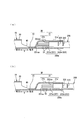
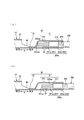
- compression-bonding part Explanatory drawing at the time of inserting the electric wire front-end
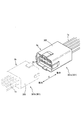
- FIG. 1 is an explanatory view of the electric wire 1 with a female crimp terminal of the first embodiment.
- FIG. 1B is a perspective view of the female crimp terminal 10 and the covered electric wire 200, and the wire tip portion 200 a is inserted into the crimp portion 30. The state just before is shown.
- FIG. 2 is a central longitudinal sectional view in the width direction of the crimping portion 30 of the electric wire 1 with the female crimp terminal.
- FIG. 2A is a sectional view showing the crimping shape of the crimping portion 30 that is crimped and connected to the tip end portion 200a.
- FIG. 2 and FIG. 2B show cross-sectional views of the wire tip portion 200a and the crimping portion 30 that are crimp-connected.
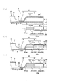
- FIG. 3 is an explanatory diagram when inserting the wire tip portion 200 a having the round mark 50 into the crimping portion 30.
- FIG. 3A shows a state immediately before the wire tip portion 200 a is inserted into the crimp portion 30.
- 3 (b) is a longitudinal sectional view showing a state immediately after the wire tip portion 200a is inserted to the center position of the mark 50 with respect to the crimping portion 30, and
- FIG. 3 (c) is a wire tip portion.
- FIG. 6 is a longitudinal sectional view showing a state in which the portion 200a is inserted into the crimping portion 30 up to a position where substantially the entire mark 50 is exposed.
- the electric wire 1 with a female crimp terminal of the present embodiment is configured by connecting a covered electric wire 200 to the female crimp terminal 10 as shown in FIG. 1 (a) and FIG. That is, the wire tip 200 a of the covered wire 200 is crimped and connected to the crimping portion 30 of the female crimp terminal 10.
- the female crimp terminal 10 allows insertion of an insertion tab in the male crimp terminal (not shown) from the front, which is the front end side in the longitudinal direction X, to the rear.
- the box portion 20 and the crimping portion 30 disposed behind the box portion 20 via the transition portion 40 having a predetermined length are integrally configured.
- the female crimp terminal 10 is made of a copper alloy strip (not shown) such as brass whose surface is tin-plated (Sn-plated), and is formed of a hollow rectangular column body as viewed from the front side in the longitudinal direction X.
- a closed barrel type terminal comprising a box portion 20 and a substantially cylindrical crimp portion 30 as viewed from the rear side, and a crimp portion of a male crimp terminal having an insertion tab inserted into the box portion 20 has the same structure. It consists of.
- the longitudinal direction X is a direction that coincides with the longitudinal direction of the covered electric wire 200 that crimps and connects the crimping portion 30, and the width direction Y is a plane with respect to the longitudinal direction X. It is a direction that intersects in the direction.
- the side of the box part 20 with respect to the crimping part 30 is defined as the front side, and conversely, the side of the crimping part 30 with respect to the box part 20 is defined as the rear side.
- the box portion 20 includes an elastic contact piece 21 that is bent toward the rear in the longitudinal direction X and contacts an insertion tab (not shown) of a male connector to be inserted. Further, the box portion 20 is bent so that the side surface portions 23 provided continuously on both sides in the width direction Y orthogonal to the longitudinal direction X of the bottom surface portion 22 are overlapped, and is substantially rectangular when viewed from the front end side in the longitudinal direction X. It is configured.
- the crimping portion 30 is formed integrally with a wire crimping portion 31 and a sealing portion 32 in this order from the rear side to the front side and in a continuous shape continuous in the entire circumferential direction.
- the sealing portion 32 is formed in a flat shape in which the front end portion of the wire crimping portion 31 is deformed so as to be crushed into a substantially flat plate shape, and the plate-like members constituting the female crimp terminal 10 are superposed. Thereby, moisture can be prevented from entering the inside of the crimping portion 30 from the distal end side of the crimping portion 30.
- the electric wire crimping portion 31 has a covering crimping portion 31a and a conductor crimping portion 31b arranged in series in this order from the rear side toward the front side.
- the wire crimping portion 31 is open only on the rear side so that the wire tip portion 200a (conductor tip portion 201a and coating tip portion 202a) can be inserted from the sheath crimping portion 31a to the conductor crimping portion 31b.
- the entire surface portion is formed in a hollow shape (cylindrical shape) that is not open.
- the coated crimping portion 31a is a portion corresponding to the coated distal end portion 202a in the longitudinal direction X of the wire crimping portion 31 in a state where the wire distal end portion 200a is inserted into the wire crimping portion 31, and is a hollow that can surround the coated distal end portion 202a. It is formed into a shape.
- the conductor crimping portion 31b is a portion corresponding to the conductor tip portion 201a in the longitudinal direction X of the wire crimping portion 31 in a state where the wire tip portion 200a is inserted into the wire crimping portion 31, and is a hollow that can surround the conductor tip portion 201a. It is formed into a shape.
- the covering crimping part 31a and the conductor crimping part 31b have a cylindrical shape having substantially the same diameter before being crimped.
- the covered electric wire 200 to be crimped and connected to the female crimp terminal 10 is formed by covering an aluminum core wire 201 in which aluminum strands are bundled with an insulating coating 202 made of an insulating resin.
- the aluminum core wire 201 is configured by bundling a plurality of aluminum alloy wires so that the cross section is 0.75 mm 2 .
- the wire tip portion 200a is a portion of the tip portion of the covered electric wire 200 that includes the sheath tip portion 202a of the insulating coating 202 and the conductor tip portion 201a of the aluminum core wire 201 in series in this order toward the tip side.
- the conductor tip 201 a is shorter than the inner length L of the crimping portion 30 of the female crimp terminal 10 on the insulating coating 202 on the tip of the covered wire 200, and has a predetermined length corresponding to the conductor crimping portion 31 b of the wire crimping portion 31. This is a portion where the aluminum core wire 201 is exposed by peeling off the portion (see FIG. 3).
- the covered tip portion 202a is a tip portion of the covered electric wire 200, and is a portion on the rear side of the covered tip surface 202aa and is a portion in which the aluminum core wire 201 is covered with the insulating coating 202.
- the wire tip portion 200 a of the covered electric wire 200 is brought into contact with the conductor tip surface 201 aa of the conductor tip portion 201 a against the sealing-side inner wall surface in the crimping portion 30.
- the circular mark 50 is marked at a position spaced from the conductor tip surface 201aa of the conductor tip part 201a by a distance corresponding to the internal length L of the crimping part 30.
- the mark 50 is a position that is spaced from the conductor tip surface 201aa of the conductor tip part 201a by a distance corresponding to the internal length L of the crimp part 30, and is a virtual reference set along the opening-side rear end part of the crimp part 30
- the line Z is marked at a position where the center of the mark 50 coincides. Further, three marks 50 are arranged at predetermined intervals in the circumferential direction along the outer peripheral surface of the coating tip portion 202a (see FIG. 3A).
- the inner length L of the crimping portion 30 is such that the coating tip portion 202a of the insulating coating 202 is exposed from the sealing-side inner wall surface of the crimping portion 30 with which the conductor tip surface 201aa of the conductor tip portion 201a abuts.
- the distance to the rear end portion on the opening side of the portion 30 is set.
- the above-described mark 50 irradiates a laser projected from a laser type marking device (not shown) at a laser marking speed of 1000 mm / s to the outer peripheral surface of the coating tip 202a in the insulating coating 202, and the laser irradiation irradiates the coating. Marking is performed by changing the color of at least a part of the outer peripheral surface of the tip part 202a to a color (specifically, black, gray, etc.) that is easily distinguishable from the insulating coating 202 in the peripheral part of the mark 50.
- the CO 2 laser has a longer wavelength than the UV laser compared to the case of marking using a UV laser, and therefore, the coated electric wire The damage to the insulating coating 202 of 200 can be reduced, and the water stoppage in the press-bonded state can be ensured.
- a shochu heated to a predetermined temperature is pressed against the outer peripheral surface of the coating tip 202a in the insulating coating 202, and the outer periphery of the coating tip 202a is heated by the heat of the shochu.
- the marking may be performed by changing the color of at least a part of the surface to a color that is easily distinguishable from the peripheral part of the mark 50.
- the mark 50 may be marked with ink by an ink jet type marking device or the like.
- marking with a laser beam from the laser marking device can mark the mark 50 with high positional accuracy.
- the number of marks 50 may be set to a desired number such as 1, 2, 3, or more.
- the shape of the mark 50 may be set to an easily distinguishable shape such as a triangle, a square, a star, a diamond, an ellipse, and an X shape, and is not limited to the number and shape of the embodiments. Absent.
- the wire tip portion 200 a of the covered wire 200 is inserted in the longitudinal direction X from the rear side to the front side with respect to the crimp portion 30 of the female crimp terminal 10, and the substantially left half of the mark 50 is the crimp portion 30. It is hidden inside and inserted to a position where the substantially right half of the mark 50 is exposed to the outside from the crimping portion 30 (see FIG. 3A).
- the wire tip portion 200a of the covered electric wire 200 is replaced with a female type. If it inserts to the position of the mark 50 mentioned above with respect to the crimping
- the conductor tip portion 201 a of the aluminum core wire 201 has reached a predetermined position in the crimp portion 30. It will be.
- the electric wire tip portion 200a of the covered electric wire 200 and the electric wire crimp portion 31 of the crimp portion 30 are crimped by a crimping jig (not shown), as shown in FIG.
- the crimping portion 30 of the female crimp terminal 10 can be crimped and connected in a predetermined crimped state (see FIG. 2).
- the wire tip portion 200a of the covered wire 200 is inserted to the position of the mark 50 described above with respect to the crimp portion 30 of the female crimp terminal 10, at least one of the marks 50 marked on the wire tip portion 200a. If the part is exposed to the outside from the crimping part 30 and a part thereof is hidden, the conductor tip 201a of the aluminum core wire 201 is a predetermined part in the crimping part 30 only by visually observing a part of the exposed mark 50. The insertion to the position can be reliably confirmed visually from the outside of the crimping portion 30.
- the insertion of the electric wire tip portion 200 a into the crimping portion 30 is shallow and under-inserted only by visually observing the entire exposed mark 50. Can be reliably visually confirmed from the outside of the crimping portion 30 (see FIG. 3C). If the entire mark 50 is hidden behind the crimping portion 30 and cannot be seen, the conductor tip 201 a of the aluminum core wire 201 is excessively inserted into the crimping portion 30.
- the aluminum core wire can be obtained only by visually observing the mark 50 exposed to the outside from the crimping portion 30. It can be confirmed visually from the outside of the crimping part 30 that the conductor tip part 201a of 201 has been inserted to a predetermined position in the crimping part 30.
- a desired energized state can be obtained if the crimping portion 30 is crimped and connected to the wire tip portion 200a while the conductor tip portion 201a of the aluminum core wire 201 is inserted into a predetermined position in the crimping portion 30.
- the shape of the mark 50 bilaterally symmetric and having a center portion that is easy to understand (for example, ⁇ )
- the center of the mark 50 and the opening-side rear end portion of the crimping portion 30 are aligned. Cheap.
- the terminal connection structure for crimping and connecting the female crimp terminal 10 and the covered electric wire 200 configured as described above is such that the aluminum core wire 201 of the covered electric wire 200 is not exposed to the outside by the sealing portion 32 at the distal end side of the crimp portion 30.
- the sealing is complete, moisture can be prevented from entering the inside of the crimping portion 30 from the front end side of the crimping portion 30 after the crimping.
- the surface of the aluminum core wire 201 is corroded and the electrical conductivity between the female crimp terminal 10 and the aluminum core wire 201 can be prevented from being lowered, and the water-stopped state can be maintained for a long period of time. Can be obtained.
- the mark 50 marked on the wire tip portion 200a is discolored in a different color from the insulating coating 202 in the peripheral portion of the mark 50, the mark 50 exposed to the outside from the crimping portion 30 and the peripheral portion of the mark 50 And the fact that the conductor tip portion 201a of the aluminum core wire 201 has been inserted to a predetermined position in the crimping portion 30 can be reliably visually confirmed from the outside of the crimping portion 30 and misidentification occurs. Can be prevented.
- the mark 50 is configured by discoloring a part of the surface of the insulating coating 202, the mark 50 does not peel off or become lighter when the wire tip portion 200a is inserted into the crimping portion 30.
- the state that can be visually confirmed can be maintained over a long period of time.
- the visual confirmation of the mark 50 may be performed by visually observing the mark, or may be confirmed through a monitor or the like by image inspection, or may be performed after image processing is performed on the inspection image.
- a crimp connection structure 1a using the female crimp terminal 10 of the electric wire 1 with the female crimp terminal configured as described above, and a crimp connection structure 1b using a male crimp terminal (not shown). 9 will be described with reference to FIG. 9.
- the crimp connection structure 1a is a connection structure using a female crimp terminal 10
- the crimp connection structure 1b is a connection structure using a male crimp end.
- the female connector 3a and the male connector 3b having reliable conductivity can be configured by attaching the above-described crimped connection structures 1a and 1b to the connector housings 300, respectively.
- both the female connector 3a and the male connector 3b are connectors of the wire harness 301 (301a, 301b). It may be a connector of the auxiliary machine.
- a crimping connection structure 1 a composed of the female crimping terminal 10 of the electric wire 1 with the female crimping terminal is mounted on a female connector housing 300, and a female connector 3 a is provided.
- the wire harness 301a is configured.
- the crimp connection structure 1b configured by the male crimp terminal is mounted on the male connector housing 300 to configure the wire harness 301b including the male connector 3b.
- the wire harness 301a and the wire harness 301b can be connected. Since the connector housing 300 is equipped with the crimp connection structures 1a and 1b, it is possible to realize connection of the wire harness 301 having reliable conductivity.
- the conductor tip 201a of the aluminum core wire 201 in the covered electric wire 200 is integrally covered by the crimp section 30. It has a sealing structure that is not exposed to the outside.
- the electrical connection state between the aluminum core wire 201 and the female crimp terminal 10 inside the crimp part 30 does not occur without causing a decrease in conductivity due to electrolytic corrosion. It can be maintained, and a connection state with reliable conductivity can be ensured.
- the wire harness 301 is configured by a plurality of crimp connection structures 1 a and 1 b, but the wire harness 301 is configured by mounting one crimp connection structure 1 a and 1 b on the connector housing 300. May be.
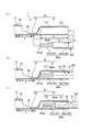
- FIG. 4 is an explanatory view when the wire tip portion 200a in which the marks 51 and 52 of the second embodiment are arranged in the front and back are inserted into the crimping portion 30, and in detail, FIG. 4 (a) shows the wire tip portion 200a.
- FIG. 4B is a vertical cross-sectional view showing a state immediately after insertion of the wire tip portion 200a to the position of the mark 51 with respect to the crimping portion 30,
- FIG. (C) is a longitudinal sectional view showing a state in which the electric wire tip portion 200a is inserted up to the position of the mark 52 with respect to the crimping portion 30.
- FIG. 4 is an explanatory view when the wire tip portion 200a in which the marks 51 and 52 of the second embodiment are arranged in the front and back are inserted into the crimping portion 30, and in detail, FIG. 4 (a) shows the wire tip portion 200a.
- FIG. 4B is a vertical cross-sectional view showing a state immediately after insertion of the wire tip portion
- the rear mark 51 is predetermined in the circumferential direction along the outer peripheral surface at a position spaced from the conductor front end surface 201aa of the conductor front end 201a of the aluminum core wire 201 by a distance corresponding to the inner length L of the crimping portion 30. Three pieces are arranged at intervals.
- the front mark 52 is closer to the tip side than the rear mark 51, and from the position of the mark 50 to the conductor tip direction, the conductor tip 201a of the aluminum core wire 201 and the conductor crimping part 31b of the crimping part 30.
- the marks 51 and 52 are arranged in the longitudinal direction Y at a distance narrower than the range in which the crimping connection is allowed in a desired conductive state between the conductor tip 201a of the aluminum core wire 201 and the conductor crimping part 31b of the crimping part 30. is doing.
- the aluminum core wire 201 of the aluminum core wire 201 can be simply seen by looking at the mark 51 exposed to the outside from the crimping portion 30. It can be confirmed visually from the outside of the crimping part 30 that the conductor tip part 201a has been inserted to a predetermined position in the crimping part 30 (see FIG. 4B). In this state, the wire tip portion 200a of the covered electric wire 200 and the crimping portion 30 of the female crimp terminal 10 are crimped and connected, so that substantially the same operations and effects as the above embodiment can be achieved.
- the insertion of the electric wire tip part 200 a into the crimping part 30 is shallow and is inserted too little simply by visually observing a part of the exposed mark 52. It can be confirmed visually from the outside of the crimping part 30 (see FIG. 4C).
- the marks 51 and 52 may be set to different colors (specifically, blue, red, etc.) that are different from the insulating coating 202 around the marks 51 and 52.
- the marks 51 may be blue. If the mark 52 is set to be red, the marks 51 and 52 and the peripheral portion can be easily distinguished from each other, so that the visual confirmation of the marks 51 and 52 exposed to the outside from the crimping portion 30 can be performed more reliably.
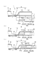
- FIG. 5 is an explanatory view when the wire tip portion 200a having the round mark 61 and the triangular mark 62 having different shapes of the third embodiment is inserted into the crimping portion 30, and more specifically, FIG. FIG. 5B is a longitudinal cross-sectional view showing a state immediately after the wire tip 200a is inserted to the position of the mark 61 with respect to the crimp 30.
- FIG. FIG. 5C is a longitudinal sectional view showing a state in which the electric wire tip portion 200a is inserted to the position of the mark 62 with respect to the crimping portion 30.
- the round mark 61 is marked on the outer peripheral surface at a position spaced apart from the conductor tip surface 201aa of the conductor tip 201a by a distance corresponding to the internal length L of the crimping portion 30.
- the triangular mark 62 is closer to the tip than the mark 61, and the conductor tip 201a of the aluminum core wire 201 and the conductor crimping part 31b of the crimping part 30 are desired from the position of the mark 62 toward the conductor tip.
- the outer peripheral surface is marked at a distance that is less than or equal to the range that is crimped and connected to the conductive state.
- the marks 61 and 62 are arranged in the longitudinal direction X at a distance narrower than the range where the conductor tip 201a of the aluminum core wire 201 and the conductor crimping part 31b of the crimping part 30 are allowed to be crimped in a desired conductive state. is doing.
- the wire tip portion 200a is inserted to a position where the opening-side rear end portion of the crimping portion 30 and the center of the mark 61 coincide with each other, only by visually observing the mark 61 exposed to the outside from the crimping portion 30, the aluminum core wire 201 It can be confirmed visually from the outside of the crimping part 30 that the conductor tip 201a has been inserted to a predetermined position in the crimping part 30. (See FIG. 5 (b)). In this state, the wire tip portion 200a of the covered electric wire 200 and the crimping portion 30 of the female crimp terminal 10 are crimped and connected, so that substantially the same operations and effects as the above embodiment can be achieved.
- the insertion of the electric wire tip part 200 a into the crimping part 30 is shallow and is inserted too little by just viewing the part of the exposed mark 62. It can be confirmed visually from the outside of the crimping part 30 (see FIG. 5C).
- the conductor tip portion 201a of the aluminum core wire 201 is a non-defective product inserted up to a predetermined position in the crimping portion 30 by arranging the mark 61 and the mark 62 in the front-rear direction. it can. Further, if the mark shapes of the marks 61 and 62 are different, it is easy to distinguish the marks and the peripheral parts, so that the visual confirmation of the marks 61 exposed to the outside from the crimping portion 30 can be performed more reliably.
- the marks 61 and 62 may be set to a color (specifically, green, red, etc.) that is easily distinguishable from the insulating coating 202 around the marks 61 and 62.
- the mark 61 is red. If the mark 62 is set to green, the color and shape of the marks 61 and 62 are different. Therefore, it is easier to distinguish the marks 61 and 62 from each other and the peripheral portion than to distinguish them by the shape alone. Visual confirmation of the marks 61 and 62 exposed outside from the part 30 can be performed more reliably.
- the structure in which the marks 50 to 52, 61, and 62 are marked by changing the color of a part of the surface of the insulating coating 202 has been described.
- a material having a color different from that of the peripheral portions of the marks 50 to 52 may be applied to at least a part of the surface of the outer peripheral surface 202.
- a color that is easily distinguished from the peripheral parts of the marks 50 to 52 by a marking device or an ink jet type marking device including screen printing or offset printing (not shown). , Green, etc. is printed or applied and marked.
- the marks 50 to 52 exposed to the outside from the crimping portion 30 and the peripheral portions of the marks 50 to 52 can be easily distinguished, and the conductor tip 201a of the aluminum core wire 201 is inserted to a predetermined position in the crimping portion 30. This can be confirmed more reliably visually from the outside of the crimping portion 30, and misidentification can be prevented.
- the marks 50 to 52, 61, 62 may be made of materials of different colors kneaded into the insulating coating 202, and the marks 50 to 52 exposed to the outside from the crimping portion 30 and the marks 50 to 52 Since it is easy to distinguish the peripheral portion, it can be visually confirmed more reliably from the outside of the crimping portion 30 that the conductor tip 201a of the aluminum core wire 201 has been inserted to a predetermined position in the crimping portion 30.
- the marks 50 to 52 are kneaded integrally with the insulating coating 202, the marks 50 to 52 may be peeled off or the color may be lightened when the wire tip portion 200a is inserted into the crimping portion 30. Without being able to be visually confirmed over a long period of time.
- FIG. 6 is an explanatory view when the wire tip portion 200a having the linear mark 71 and the broken line mark 72 of the fourth embodiment is inserted into the crimping portion 30, and in detail, FIG. FIG. 6B is a longitudinal cross-sectional view showing a state immediately after inserting the electric wire front end portion 200a to the position of the mark 71 with respect to the crimping portion 30.
- FIG. FIG. 6 and FIG. 6C are longitudinal sectional views showing a state in which the wire tip portion 200a is inserted to the position of the mark 72 with respect to the crimping portion 30.
- the linear mark 71 is marked in the circumferential direction along the outer peripheral surface at a position spaced from the conductor front end surface 201aa of the conductor front end portion 201a by a distance corresponding to the internal length L of the crimping portion 30.
- the broken-line mark 72 is closer to the tip side than the mark 71, and the conductor tip 201a of the aluminum core wire 201 and the conductor crimping part 31b of the crimping part 30 are desired from the position of the mark 71 toward the conductor tip. Marking is performed in the circumferential direction along the outer peripheral surface of the insulating coating 202 at a distance that is less than or equal to the range of crimping connection in the conductive state.
- the marks 71 and 72 are arranged in the longitudinal direction Y at a distance narrower than the range where the conductor tip 201a of the aluminum core wire 201 and the conductor crimping part 31b of the crimping part 30 are allowed to be crimped in a desired conductive state. is doing. Note that the positions or intervals of the marks 71 and 72 may be set with reference to, for example, the conductor tip surface 201aa of the conductor tip 201a and the coating tip surface 202aa of the coating tip 202a.
- the above-mentioned marks 71 and 72 are easily distinguishable colors (specifically, different from the insulating coating 202 in the peripheral portions of the marks 71 and 72 in a marking device or an ink jet type marking device including screen printing or offset printing (not shown). Red, green, etc.) ink is printed or applied for marking. For example, if the mark 71 is set to red and the mark 72 is set to green, the line types and colors of the marks 71 and 72 are different, so that it is easy to distinguish.
- the conductor of the aluminum core wire 201 can be obtained only by visually observing the mark 71 exposed to the outside from the crimping portion 30. It can be confirmed visually from the outside of the crimping part 30 that the tip part 201a has been inserted to a predetermined position in the crimping part 30 (see FIG. 6B). In this state, the crimping portion 30 of the female crimp terminal 10 is crimped and connected to the wire tip portion 200a of the covered electric wire 200, so that substantially the same operations and effects as in the above embodiment can be achieved.
- the mark 72 is exposed to the outside from the crimping portion 30, it is confirmed that the insertion of the wire tip portion 200 a into the crimping portion 30 is shallow and the insertion is excessively only by visually observing the exposed mark 72. This can be confirmed visually from the outside of the portion 30 (see FIG. 6C).
- the conductor tip portion 201a of the aluminum core wire 201 is a non-defective product inserted up to a predetermined position in the crimping portion 30 by arranging the mark 71 and the mark 72 in the front-rear direction. it can. Further, since the line types and colors of the marks 71 and 72 are different, the marks 71 and 72 and the peripheral part are more easily distinguished from each other and can be distinguished from the line type alone, and the marks exposed to the outside from the crimping part 30. Visual confirmation of 71 and 72 can be performed more reliably.
- the marking 72 in the circumferential direction is provided along the outer peripheral surface of the insulating coating 202 and a broken mark 72 is provided, the mark becomes a water passage and the mark along the longitudinal direction Y may decrease water stoppage. Compared to the case where the mark is marked, it is possible to obtain a certain water-stopping property in the pressure-bonded state.
- FIG. 7 is an explanatory view when the wire tip portion 200a having the wide mark 80 of the fifth embodiment is inserted into the crimping portion 30.
- FIG. 7A shows the wire tip portion 200a as the crimping portion 30.
- FIG. 7B is a longitudinal cross-sectional view showing a state immediately after inserting the electric wire front end portion 200a to the position where the rear end of the mark 80 is exposed with respect to the crimping portion 30.
- FIG. FIG. 7C is a longitudinal sectional view showing a state in which the electric wire tip portion 200a is inserted to the crimping portion 30 up to a position where the front end of the mark 80 is hidden.
- the wide mark 80 is formed wide along the longitudinal direction X of the covered electric wire 200.
- the width of the mark 80 in the longitudinal direction X is set to a width corresponding to a range in which the conductor tip 201a of the aluminum core wire 201 and the conductor crimping part 31b of the crimping part 30 are crimped and connected in a desired conductive state.
- the rear end side of the mark 80 is formed on the outer peripheral surface of the insulating coating 202 including a position spaced from the conductor front end surface 201aa of the conductor front end portion 201a by a distance corresponding to the inner length L of the crimping portion 30.
- the front end side of the mark 80 is closer to the front end side than the rear end side of the mark 80, and from the rear end side to the conductor front end direction, the conductor front end portion 201a of the aluminum core wire 201 and the conductor crimping portion 31b of the crimping portion 30 are arranged.
- the mark 80 is made of a material such as synthetic resin that is more flexible than the insulating coating 202, and is arranged in the circumferential direction so as to cover the outer peripheral surface along the outer peripheral surface of the coating tip 202a of the insulating coating 202. is doing.
- the aluminum 80 can be obtained only by visually observing the mark 80 exposed to the outside from the crimping portion 30. It can be confirmed visually from the outside of the crimping part 30 that the conductor tip part 201a of the core wire 201 has been inserted to a predetermined position in the crimping part 30 (see FIG. 7B). In this state, the crimping portion 30 of the female crimp terminal 10 is crimped and connected to the wire tip portion 200a of the covered electric wire 200, so that substantially the same operations and effects as in the above embodiment can be achieved.
- the amount of insertion of the electric wire tip 200a into the crimping part 30 is shallow and only a small amount is inserted just by looking at the exposed mark 80. It can be confirmed visually from the outside of the crimping part 30 (see FIG. 7C).
- the front end side of the mark 80 is hidden behind the crimping part 30 and cannot be seen, and the conductor tip part 201a of the aluminum core wire 201 is inserted into an insertion state in which the rear end side of the mark 80 is exposed to the outside from the crimping part 30. It is possible to more reliably determine whether the product is a non-defective product inserted up to a predetermined position in the crimping portion 30.
- the highly flexible mark 80 easily deforms following the crimped shape and is excellent in followability to the shape change.
- the surface facing the crimping portion 30 is in a close contact state and water is stopped. As a result, it is possible to prevent moisture from entering the inside of the crimping portion 30 and to ensure excellent water-stopping properties.
- the mark 80 formed in the outer peripheral surface of the insulating coating 202 in a wide and circumferential direction along the longitudinal direction X of the covered electric wire 200 is provided, the mark may become a passage for water and the water stoppage may be lowered. Compared to the case where the mark is marked along the longitudinal direction Y, it is possible to obtain a certain water stoppage in the crimped state.
- FIG. 8 is an explanatory view when the wire tip portion 200a having the band-shaped mark 90 of the sixth embodiment is inserted into the crimping portion 30.
- FIG. 8A shows the wire tip portion 200a as the crimping portion 30.
- FIG. 8B is a longitudinal sectional view showing a state immediately after the wire tip portion 200a is inserted to the center position of the mark 90 with respect to the crimping portion 30,
- FIG. 8C. Is a longitudinal sectional view showing a state in which the electric wire tip portion 200a is inserted to a position where the front end side of the mark 90 is hidden with respect to the crimping portion 30.
- FIG. 8A shows the wire tip portion 200a as the crimping portion 30.
- FIG. 8B is a longitudinal sectional view showing a state immediately after the wire tip portion 200a is inserted to the center position of the mark 90 with respect to the crimping portion 30,
- FIG. 8C Is a longitudinal sectional view showing a state in which the electric
- the band-shaped mark 90 is a conductor tip portion of the aluminum core wire 201 from a position corresponding to the inner length L of the crimping portion 30 from the conductor tip surface 201aa of the conductor tip portion 201a toward the conductor tip direction.
- the length 201a and the conductor crimping portion 31b of the crimping portion 30 are formed to have a length equal to or shorter than a range in which the conductor is crimped and connected to a desired conductive state.
- the mark 90 is marked by changing the color of at least a part of the outer peripheral surface of the coating tip 202a to a color that is easily distinguishable from the insulating coating 202 in the peripheral part of the mark 90 with a cautery or the like.
- the wire tip portion 200a of the covered electric wire 200 marked with the above-described mark 90 is inserted to a position where the opening-side rear end portion of the crimp portion 30 in the female crimp terminal 10 and the substantially central portion of the mark 90 substantially coincide. It is confirmed that the conductor tip 201a of the aluminum core wire 201 is inserted to a predetermined position with respect to the conductor crimping part 31b of the crimping part 30 only by visually observing the mark 90 exposed to the outside from the crimping part 30. It can be confirmed visually from the outside of 30 (see FIGS. 8A and 8B). In this state, the wire tip portion 200a of the covered electric wire 200 and the crimping portion 30 of the female crimp terminal 10 are crimped and connected, so that substantially the same operations and effects as the above embodiment can be achieved.
- the insertion amount of the electric wire tip part 200a with respect to the crimping part 30 is shallow and it is inserted too little just by looking at the exposed mark 90. It can be confirmed visually from the outside of the crimping portion 30 (see FIG. 8C). If the rear end side of the mark 90 is hidden behind the crimping portion 30 and cannot be seen, the conductor tip 201 a of the aluminum core wire 201 is excessively inserted into the conductor crimping portion 31 b of the crimping portion 30.
- the conductor tip portion 201a of the aluminum core wire 201 is inserted into an insertion state in which the front end side of the mark 90 is hidden behind the crimping portion 30 and cannot be seen and the rear end side of the mark 90 is exposed to the outside from the crimping portion 30. It is possible to more reliably determine whether the product is a non-defective product inserted up to a predetermined position in the crimping portion 30.
- the mark 90 is made of a material having a thickness, for example, if it is made of a material having flexibility, when the crimping portion 30 is crimped and connected to the electric wire tip portion 200a, the crimping shape of the crimping portion is followed. And since the mark 90 deform
- the mark 80 of the fifth embodiment and the mark 90 of the sixth embodiment may be configured in a different color from the insulating coating 202 around the marks 80 and 90, and the mark exposed to the outside from the crimping portion 30.
- 80 and 90 and the peripheral portions of the marks 80 and 90 can be easily distinguished, and the visual confirmation of the marks 80 and 90 exposed to the outside from the crimping portion 30 can be performed more reliably.
- the marks 80 and 90 may be formed by changing the color of the surface of the insulating coating 202 (forming a change in quality) or printing on the surface, or by kneading a material having a color different from that of the insulating coating 202.
- the marks 51 and 52 are spaced apart from each other by a narrower distance than the range where the conductor tip 201a of the aluminum core wire 201 and the conductor crimping part 31b of the crimping part 30 are allowed to be crimped in a desired conductive state.
- the round marks 51X and 52X are arranged so that the serration portion corresponding to the conductor tip portion 201a of the aluminum core wire 201 in the crimp portion 30 is the entire area. You may arrange
- FIG. 10 is an explanatory diagram when inserting the wire tip portion 200a having the marks 51X and 52X of the seventh embodiment into the crimping portion 30, and in detail, FIG. 10A shows the wire tip portion 200a as the crimping portion 30.
- 10B is a longitudinal sectional view showing a state immediately after insertion to the center position of the mark 51X, and FIG. 10B shows a state in which the wire tip portion 200a is inserted to the crimping portion 30 to a position where substantially the entire mark 52X is hidden. It is a longitudinal cross-sectional view shown.
- a serration 33 that is a groove in the width direction Y into which the aluminum core wire 201 bites into the inner peripheral surface of the conductor crimping portion 31b in the crimping portion 30 in a state where the aluminum core wire 201 is crimped is spaced apart in the longitudinal direction X by a predetermined interval. Three are formed.
- the serration 33 is formed in a groove shape continuous in the width direction Y from the inner center bottom surface of the conductor crimping portion 31b to both inner side surfaces.
- the mark 51X is separated from the conductor tip surface 201aa of the conductor tip 201a in the aluminum core wire 201 by a distance corresponding to the amount of insertion that is crimped so that the conductor tip 201a contacts the serration portion of the crimping part 30 in the entire area.
- the insulating coating 202 is formed on the outer peripheral surface including the position.
- the mark 52X is separated from the position of the mark 51X by a distance corresponding to a range in which the serration portion including the serration 33 including the serration 33 of the crimping portion 30 is in contact with the entire region from the position of the mark 51X. It is arranged at the position. That is, the marks 51X and 52X are arranged in the longitudinal direction X with an interval corresponding to a range in which the crimping connection is allowed in a desired conductive state between the conductor tip 201a of the aluminum core wire 201 and the conductor crimping part 31b of the crimping part 30. It is arranged.
- the wire tip 200a of the covered electric wire 200 marked with the marks 51X and 52X is inserted to a position where the opening-side rear end of the crimp portion 30 in the female crimp terminal 10 and the center of the mark 51X coincide with each other,
- the conductor tip 201a of the aluminum core wire 201 is inserted to a predetermined position in the crimping portion 30, and the substantially entire length of the range where the serration portion of the crimping portion 30 can be crimped and connected. Can be visually confirmed from the outside of the crimping portion 30 (see FIG. 10A).
- the entire mark 52X is hidden behind the crimping portion 30 and cannot be seen, and the entire mark 51X is exposed to the outside from the crimping portion 30, at least the conductor tip 201a can be seen only by looking at the exposed mark 51X. It can be visually confirmed from the outside of the crimping portion 30 that the distal end side is inserted in a state where the serration portion of the crimping portion 30 can be crimped and connected. Crimp connection can be made so as to contact the entire area of the serration portion (see FIG. 10B).
- the conductor tip 201a is a non-defective product inserted up to a predetermined position where the conductor tip 201a is crimped by the serration portion of the crimping part 30. Can be determined.
- the configuration of the seventh embodiment described above can also be applied to the marks 51 and 52 of the second embodiment, the marks 61 and 62 of the third embodiment, and the marks 71 and 72 of the fourth embodiment. it can.
- the mark 80 is formed in a width corresponding to the range in which the conductor tip 201a of the aluminum core wire 201 and the conductor crimping part 31b of the crimping part 30 are crimped and connected in a desired conductive state.
- the mark 80X is formed to have a width corresponding to the crimping connection range so that the serration portion of the conductor tip 201a and the crimping portion 30 are in contact with each other. May be.
- FIG. 11 is an explanatory view when the wire tip portion 200a having the wide mark 80X of the eighth embodiment is inserted into the crimping portion 30.
- FIG. 11A shows the wire tip portion 200a as the crimping portion 30.
- 11B is a longitudinal cross-sectional view showing a state immediately after insertion to the position where the rear end side of the mark 80X is exposed,
- FIG. 11B shows the electric wire front end portion 200a to the position where the front end side of the mark 80X is hidden from the crimping portion 30.
- It is a longitudinal cross-sectional view which shows the state inserted.
- the mark 80 ⁇ / b> X is formed wide along the longitudinal direction X of the covered electric wire 200.
- the width in the longitudinal direction X of the mark 80X is set to a width corresponding to a range in which the conductor tip 201a of the aluminum core wire 201 and the conductor crimping part 31b of the crimping part 30 are crimped and connected in a desired conductive state.
- the mark 80X is located at a distance from the conductor tip surface 201aa of the conductor tip portion 201a at a distance corresponding to the insertion amount that is crimped so that the conductor tip portion 201a contacts the serration portion of the crimping portion 30 in the entire area. It is formed on the outer peripheral surface of the insulating coating 202 including
- the front end side of the mark 80X is closer to the front end side than the rear end side of the mark 80X, and a serration portion provided with a serration 33 of the conductor front end portion 201a and the crimping portion 30 from the rear end side to the conductor front end direction. It is formed on the outer peripheral surface at a position that is separated from the range to be crimped so as to be in contact with the entire region.
- wire tip portion 200a of the covered electric wire 200 on which the above-described mark 80X is formed is inserted to a position where the opening-side rear end portion of the crimp portion 30 in the female crimp terminal 10 and the rear end side of the mark 80X substantially coincide.
- the conductor tip 201a of the aluminum core wire 201 is inserted to a predetermined position in the crimping part 30 only by visually observing the mark 80X exposed to the outside from the crimping part 30, and the substantially full length of the conductor tip 201a is It can be visually confirmed from the outside of the crimping portion 30 that the conductor crimping portion 31b is inserted in a state where the crimping connection is allowed (see FIG. 11A).
- the tip of the conductor tip portion 201a can be seen only by looking at the exposed mark 80X. It can be visually confirmed from the outside of the crimping part 30 that the side is inserted in a state where the serration part of the crimping part 30 can be crimped and connected, and the conductor tip 201a is serrated on the crimping part 30. It can be crimped and connected so as to be in contact with the entire region (see FIG. 11B).
- the front end side of the mark 80X is hidden behind the crimping portion 30 and cannot be seen, and the conductor tip portion 201a is crimped by being inserted into an insertion state in which the rear end side of the mark 80X is exposed to the outside from the crimping portion 30. It is possible to more reliably determine whether the product is a non-defective product inserted up to a predetermined position to be crimped at the serration portion of the portion 30.
- the mark 80X that is wide and circumferentially formed along the longitudinal direction X of the covered electric wire 200 is provided on the outer peripheral surface of the insulating coating 202, the mark may become a passage for water and the water stoppage may be reduced. Compared to the case where the mark is marked along the longitudinal direction Y, it is possible to obtain a certain water stoppage in the crimped state.
- FIG. 12 is an explanatory diagram when inserting the wire tip portion 200a having the linear mark 80Z of the ninth embodiment into the crimping portion 30, and in detail, FIG. 12 (a) shows the wire tip portion 200a as the mark 80Z.
- FIG. 12B is a longitudinal sectional view showing a state in which the center portion in the longitudinal direction X of the wire and the opening side rear end portion of the crimping portion 30 coincide with each other.
- FIG. FIG. 12C is a longitudinal cross-sectional view showing a state in which the electric wire tip 200a is inserted to a position where the front end of the mark 80Z is hidden inside the crimping portion 30. It is.
- the linear mark 80 ⁇ / b> Z is marked obliquely across the longitudinal direction X of the insulating coating 202 with respect to the outer peripheral surface of the insulating coating 202 in the covered electric wire 200.
- the length from the front end to the rear end in the longitudinal direction X in the mark 80Z corresponds to the range in which the conductor tip 201a of the aluminum core wire 201 and the conductor crimping part 31b of the crimping part 30 are crimped and connected in a desired conductive state.
- the length is set. That is, the length corresponding to the crimping connection range is set so that the serration portion where the serration 33 of the conductor crimping portion 31b is formed is in contact with the conductor tip portion 201a of the aluminum core wire 201.
- the rear end of the mark 80Z has an outer peripheral surface of the insulating coating 202 including a position that is spaced from the conductor front end surface 201aa by a distance corresponding to the inner length L of the crimping portion 30 with respect to the conductor front end surface 201aa of the conductor front end 201a. Is formed.
- the front end of the mark 80Z is closer to the front end side than the rear end of the mark 80Z, and the conductor front end portion 201a of the aluminum core wire 201 and the conductor crimping portion 31b of the crimping portion 30 are desired from the rear end to the conductor front end direction. It is formed on the outer peripheral surface of the insulating coating 202 at a distance corresponding to the range to be crimped and connected in the conductive state.
- the mark 80Z intersects the opening-side rear end portion of the crimp portion 30. Is inserted to a position where the center of the mark 80Z in the longitudinal direction X coincides with the opening-side rear end of the crimping portion 30.
- the crimping connection of the conductor tip 201a of the aluminum core wire 201 to the conductor crimping part 31b of the crimping part 30 is appropriate without the insertion of the wire tip 200a into the crimping part 30 being too shallow or too deep. Can be reliably inserted up to the position (see FIG. 12A).
- the mark 80Z formed on the insulating coating 202 of the wire tip 200a in the covered wire 200 and the opening-side rear end of the crimp portion 30 in the female crimp terminal 10 are inserted to a position where they intersect, the front end of the mark 80Z
- the rear side of the mark 80 ⁇ / b> Z is exposed to the outside from the opening side rear end of the crimping part 30.
- the crimping part 30 indicates that the conductor tip 201a of the aluminum core wire 201 has been inserted into the conductor crimping part 31b of the crimping part 30 up to a predetermined position. It can be confirmed visually from the outside.
- the conductor crimping portion 31b of the crimping portion 30 of the female crimp terminal 10 is crimped and connected to the conductor leading end portion 201a of the aluminum core wire 201 of the wire leading end portion 200a of the covered electric wire 200. It can be crimped and connected in a crimped state, and can exhibit substantially the same operations and effects as the above embodiment.
- the wire tip 200a When the wire tip 200a is inserted into the crimping portion 30, if the entire mark 80Z is hidden behind the crimping portion 30, the wire tip 200a is deeply inserted into the crimping portion 80Z and excessively inserted. Moreover, if the whole mark 80Z is exposed from the crimping
- the opening-side rear end portion of the crimping portion 30 is positioned within a range corresponding to the interval between the front end and the rear end in the longitudinal direction X in the mark 80Z. If inserted, it can be crimped and connected in good condition.
- the mark 80Z is inserted until the rear end of the mark 80Z is exposed to the outside from the opening-side rear end of the crimping part 30 (see FIG. 12B), or the front end of the mark 80Z is inside the crimping part 30.
- the rear end side of the mark 80Z is always exposed to the outside from the opening side rear end portion of the crimping portion 30.
- the conductor tip 201a of the aluminum core wire 201 is contained within a range where the serration part of the conductor crimping part 31b can be crimped and connected. It can be confirmed visually from the outside of the crimping part 30. Therefore, the conductor tip 201a can be crimped and connected so that it contacts the entire serration portion of the conductor crimping portion 31b.
- the linear auxiliary mark 100 may be marked on the exposed outer peripheral surface of the insulating coating 202 exposed to the outside from the opening-side rear end portion of the crimping portion 30.
- FIG. 13 is an explanatory diagram when the wire tip portion 200 a having the linear auxiliary mark 100 of the tenth embodiment is inserted into the crimping portion 30. Specifically, the wire tip portion 200 a is marked with respect to the crimping portion 30. It is a longitudinal cross-sectional view which shows the state inserted to the position which 50 hides.
- the linear auxiliary mark 100 is the outer peripheral surface of the exposed side of the insulating coating 202 exposed to the outside from the opening side rear end of the crimping part 30 when the mark 50 is marked by the laser type marking device described above. Are marked in the circumferential direction. That is, even if the tip end 200a of the covered electric wire 200 is inserted deeply into the crimping portion 30 of the female crimp terminal 10 and the mark 50 marked on the insulating coating 202 is hidden behind the crimping portion 30 and cannot be seen, By visually observing the auxiliary mark 100 attached to the exposed outer peripheral surface of the coating 202, it can be confirmed from the outside of the pressure-bonding part 50 that the mark 50 is attached to the part hidden behind the pressure-bonding part 30. .
- the auxiliary mark 100 may be marked on a part of the exposed outer peripheral surface of the insulating coating 202.
- the crimp terminal of the present invention corresponds to the female crimp terminal 10 of the embodiment
- the crimping part corresponds to the closed barrel type crimping part 30
- the conductor corresponds to the aluminum core wire 201
- the rear landmarks correspond to the landmarks 51, 51X, 61, 71
- the front side mark corresponds to the mark 52, 52X, 62, 72
- the connection structure corresponds to the crimp connection structure 1a, 1b
- the connectors correspond to the female connector 3a and the male connector 3b.
- the front end side end surface of the electric wire front end portion 200a corresponds to the conductor front end surface 201aa of the conductor front end portion 201a and the covering front end surface 202aa of the covering front end portion 202a.
- the present invention is not limited to the configuration of the above-described embodiment, but can be applied based on the technical idea shown in the claims, and many embodiments can be obtained.
- the insulation coating 200 extends rearward in the longitudinal direction X due to the crimping pressure acting on the crimping portion 30.
- the mark 50 marked on the wire tip portion 200a moves backward with respect to the crimping portion 30.
- the mark 50 that should be located inside the crimping portion 30 is extended by the crimping portion 30 due to the expansion of the insulating coating 200 due to the crimping. There is a risk of exposure from the rear edge.
- the mark 50 is formed at a position that takes into consideration the amount of movement based on the extension of the insulating coating 200 to the rear by the behavior analysis at the time of crimping of the crimping portion 30 by a predetermined analyzing means (not shown).
- the conductor tip surface 201aa of the conductor tip 201a is used as a reference as a reference for determining the position of the mark.
- the conductor tip of the conductor tip 201a is removed.
- the distance from the surface 201aa to the coating tip surface 202aa of the coating tip 202a is constant. For this reason, the coating tip surface 202aa may be used as a reference.
- a male crimp terminal composed of an insertion tab inserted into and connected to the box section 20 and a crimp section 30 is composed only of the crimp section 30 and is a crimp terminal for bundling and connecting the aluminum core wires 201 of a plurality of covered electric wires 200. It may be.
- the terminal connection structure of the covered electric wire 200 of the present invention can be applied to, for example, a connection structure in which an open barrel-type crimping portion is crimped and connected to the wire tip portion 200 a of the covered electric wire 200. That is, since it can be visually confirmed from the outside of the crimping portion that the conductor tip 201a of the aluminum core wire 201 has been inserted to a predetermined position in an unillustrated open barrel-type crimping portion, it is substantially equivalent to the above embodiment. The effects and effects of can be achieved.
- the above-mentioned mark may be marked on the conductor tip of the aluminum core wire exposed on the tip side of the covered wire. Furthermore, the mark may be readable by, for example, an optical sensor or an image reading device.
- the laser beam emitted from the laser marking device is irradiated, or the mark is marked by printing or applying ink with the marking device or the ink jet marking device. Marks may be marked.
- the flow of the coated electric wire 200 is temporarily stopped in the production line, and the mark is marked after being sandwiched by the stamp. Productivity is higher when marking is possible by applying laser or ink.
- SYMBOLS 1 Electric wire with a female crimp terminal 1a, 1b ... Crimp connection structure 3a ... Female connector 3b ... Male connector 10 ... Female crimp terminal 20 ... Box part 30 ... Crimp part 31 ... Electric wire crimp part 31b ... Conductor crimp part 32 ... Sealing part 33 ... Serration 50, 51, 51X, 52, 52X ... Mark 61, 62, 71, 72 ... Mark 80, 80X, 80Z, 90 ... Mark 100 ... Auxiliary mark 200 ... Covered wire 200a ... Wire tip DESCRIPTION OF SYMBOLS 201 ... Aluminum core wire 201a ... Conductor front-end
Landscapes
- Engineering & Computer Science (AREA)
- Manufacturing & Machinery (AREA)
- Connections Effected By Soldering, Adhesion, Or Permanent Deformation (AREA)
- Manufacturing Of Electrical Connectors (AREA)
Abstract
Description
特許文献1に開示の圧着端子は、被覆電線における先端側の絶縁被覆を剥がして導体を露出させた電線先端部を、先端側が閉じられた圧着部の挿入穴に挿入し、その電線先端部に圧着部を圧着接続する構成である。
この結果、被覆電線における電線先端部の導体と、圧着端子における圧着部とを所定の圧着状態に圧着接続することができるとともに、所望する導電状態が得られる端子接続構造を構成することができる。
なお、上述した目印の位置は、例えば、圧着部に挿入される電線先端部の挿入長さに応じて所望する位置に変更してもよい。
この発明によれば、電線先端部が圧着部の内部長さと対応する長さだけ挿入されたことを、該圧着部の外部から目視で確認することができる。
さらに、後側目印あるいは前側目印が圧着部より露出しているか目視することによって、導体が圧着部内の所定位置まで挿入されているか、該圧着部の外部から確実に目視で確認することができる。
この発明によれば、圧着部より外部に露出された目印を目視するだけで、電線先端部が圧着部に対して所定長さ挿入されたことを、該圧着部の外部から目視で確認することができる。
また、目印の前端側が圧着部より外部に露出していれば、導体先端部が圧着部の圧着接続が許容される範囲よりも後方に位置することになり、電線先端部の圧着部に対する挿入が浅く、過少挿入されていることになる。
さらに、圧着部より露出される目印の露出幅を目視することにより、導体が圧着部内の所定位置まで挿入されたことを、該圧着部の外部から確実に目視で確認することができる。
この発明によれば、被覆電線と圧着部との対向面間を止水するための止水性と、電線先端部が圧着部内の所定位置まで挿入されたことを目視で確認するための目印として兼用することができる。
これに対し、本発明の被覆電線の端子接続構造は、目印を、絶縁被覆よりも柔軟性を有する材料で構成し、絶縁被覆の外周面を覆うように周方向に配置しているので、被覆電線の電線先端部を、圧着端子の圧着部に対して上述の目印の位置まで挿入して、図示しない圧着治具により電線先端部に圧着部を圧着接続した際、被覆電線に圧着部を直接圧着するよりも、高い柔軟性を有する目印が圧着形状に追随して変形しやすく、形状変化に対する追随性に優れているため、電線先端部と圧着部との対向面間が密着状態となり止水される。
この結果、圧着部の内部へ水分が侵入することを防止でき、優れた止水性を確保することができる。
ここで、上述の柔軟性を有する材料は、例えば、ゴム、ゲル材、接着剤、粘着剤等で構成することができる。
この発明によれば、絶縁被覆に形成した目印を他の部分と異なる色に変色させているので、目印の目視確認がより確実に行える。
ここで、上述の変色とは、例えば、絶縁被覆の表面に対してレーザーを照射したり、焼き鏝を押し付ける等して一部表面を変色する変色手段にて構成することができる。
この発明によれば、絶縁被覆に形成した目印を他の部分と異なる色の材料を付与して構成しているので、目印の目視確認がより確実に行える。
ここで、上述の付与とは、例えば、判別しやすい色のインクや顔料からなる目印を印刷又は塗布する等のマーキング手段にて構成することができる。
この発明によれば、目印の目視確認がより確実に行えるとともに、目印として判別しやすい状態を長期に亘って維持することができる。
上述した構成によれば、例えば、クローズドバレル型の圧着部に挿入された電線先端部を、該圧着部の外部から目視で確認することが困難であるが、本発明の端子接続構造を採用することによって、電線先端部に露出した導体が圧着部内の所定位置まで挿入されたことを、該圧着部の外部から確実に目視で確認することができる。
上述した構成によれば、圧着部の先端側を封止部にて封止しているため、圧着部に挿入された電線先端部を、該圧着部の先端側から目視で確認することが不可能であり、電線先端部が圧着部に対して適切な深さ挿入されたか確認することができない。
さらに、封止部を、圧着部の対向する内面同士を密着させて構成しているので、圧着部の内部に、該圧着部の先端側から水分が浸入することを防止でき、安定した導電性を確保することができる。
この発明によれば、銅線による導体部分を有する被覆電線に比べて軽量化できるとともに、上述した封止部によって確実な止水性が得られるので、いわゆる異種金属腐食(以下において電食という)を防止することができる。
ここで、前記圧着部は、例えば、銅、銅合金等の銅系材料で構成することができる。また、導体は、例えば、アルミニウム製素線あるいはアルミニウム合金製素線等で構成することができる。
なお、複数本の端子接続構造で構成したワイヤハーネス、あるいは1本の端子接続構造で構成したワイヤハーネスとすることができる。
この発明によれば、確実な導電性を備えた接続状態を確保することができる。
上述した被覆電線の電線先端部を、圧着端子の圧着部に対して目印の位置まで挿入する場合、例えば、目印の一部が圧着部より外部に露出していてかつ一部が隠れる位置まで挿入すれば、電線先端部に露出した導体を圧着部内の所定位置まで挿入することができる。
詳しくは、例えば、被覆電線の電線先端部を、圧着端子の先端側が閉じられた圧着部に挿入した際、目印の全体が圧着部から露出していれば、電線先端部の圧着部に対する挿入が浅く、過少挿入されていることになる。
この発明によれば、被覆電線における電線先端部の導体を、圧着端子における圧着部内の所定位置まで確実に挿入することができる。
この結果、被覆電線における電線先端部の導体と、圧着端子における圧着部とを、より確実に所定の圧着状態に圧着接続することができる。
詳しくは、例えば、目印を、被覆電線における絶縁被覆の外周面に付設してから、電線ストリップ装置によって先端側の絶縁被覆を所定長さ分だけ剥ぎ取る場合、導体の導体先端部が、絶縁被覆の被覆先端面よりも奥の方に入り込んでいると、絶縁被覆より露出される導体先端部の露出長さが短くなり、所望の導電状態に圧着接続するのに必要な導体露出長さを確保することができない。
この結果、被覆電線における電線先端部の導体と、圧着端子における圧着部とを、より正確かつ確実に所定の圧着状態に圧着接続することができる。
この発明によれば、圧着端子の圧着部より露出される部分に付設した補助目印を目視するだけで、該圧着部に隠れて見えなくなった部分に目印が付設されていることを、該圧着部の外部から確実に確認することができる。
この結果、被覆電線の電線先端部を圧着端子の圧着部から抜き取らなくても、上述の目印が付設済みであることを、圧着部の外部から確実に目視で確認することができる。
(第1実施形態)
図面は雌型圧着端子10と被覆電線200とを圧着接続した端子接続構造を示し、図1は第1実施形態の雌型圧着端子付き電線1の説明図であり、詳しくは、図1(a)は雌型圧着端子10と被覆電線200とを圧着接続した斜視図、図1(b)は雌型圧着端子10と被覆電線200の斜視図で、電線先端部200aを圧着部30に挿入する直前の様子を示している。
また、ボックス部20は、底面部22の長手方向Xと直交する幅方向Yの両側部に連設された側面部23を重なり合うように折り曲げて、長手方向Xの先端側から見て略矩形状に構成している。
封止部32は、電線圧着部31よりも前方端部を略平板状に押し潰すように変形させて、雌型圧着端子10を構成する板状同士が重合する偏平形状で構成している。これにより、圧着部30の内部に、該圧着部30の先端側から水分が浸入することを防止できる。
なお、被覆圧着部31a、及び導体圧着部31bは、圧着前の状態においては互いに略同じ径をした筒状である。
また、被覆先端部202aは、被覆電線200の先端部分であるが、被覆先端面202aaよりも後方側部分であって、アルミニウム芯線201を絶縁被覆202で被覆した部分である。
なお、目印50の全体が圧着部30に隠れて見えなければ、アルミニウム芯線201の導体先端部201aが圧着部30に対して過剰に挿入されていることになる。
なお、目印50の形状を左右対称でかつ中央部がわかりやすい形状(例えば、∞等)とすることで、目印50の中心と圧着部30の開口側後端部とが一致するように位置合わせしやすい。
この結果、雌型圧着端子10と、被覆電線200のアルミニウム芯線201を構成する金属種によらず、安定した導電性を確保した接続状態の端子接続構造を構成することができる。しかしながら、もちろん銅系材料で構成する素線を束ねた芯線を絶縁被覆202で被覆した被覆電線を用いてもよい。
なお、目印50の目視確認は、直接目印を目視してもよく、画像検査により、モニタなどを通して確認してもよく、さらには、検査画像に画像処理を施してから目視してもよい。
なお、圧着接続構造体1aは、雌型圧着端子10を用いた接続構造体であり、圧着接続構造体1bは、雄型圧着端を用いた接続構造体である。
また、雄型圧着端子で構成した圧着接続構造体1bを、雄型のコネクタハウジング300に装着して、雄型コネクタ3bを備えたワイヤハーネス301bを構成する。
コネクタハウジング300には、圧着接続構造体1a,1bを装着しているため、確実な導電性を備えたワイヤハーネス301の接続を実現することができる。
(第2実施形態)
上述の第1実施形態では、目印50を、圧着部30の内部長さLと対応する距離を隔てた位置に1つマーキングした例を説明したが、図4に示す第2実施形態のように、丸形の目印51,52を、圧着部30の内部長さLと対応する距離を隔てた位置と、該位置より先端側寄りの位置とに分けて複数マーキングしてもよい。
さらに、目印51,52は、アルミニウム芯線201の導体先端部201aと圧着部30の導体圧着部31bとが所望の導電状態に圧着接続が許容される範囲より狭い間隔を隔てて長手方向Yに配置している。
この状態で、被覆電線200の電線先端部200aと、雌型圧着端子10の圧着部30を圧着接続するので、前記実施形態と略同等の作用及び効果を奏することができる。
続いて、上述の第2実施形態では、同一形状の目印51,52を、絶縁被覆202の一部表面を変色させてマーキングした構成について説明したが、図5に示す第2実施形態のように、異なる形状の丸形目印61と三角目印62とを長手方向Xに対して所定間隔を隔ててマーキングしてもよい。
一方、三角の目印62は、目印61よりも先端側寄りで、該目印62の位置から導体先端方向に対して、アルミニウム芯線201の導体先端部201aと圧着部30の導体圧着部31bとが所望の導電状態に圧着接続される範囲以下の距離を隔てた位置の外周面にマーキングしている。
さらに、目印61,62は、アルミニウム芯線201の導体先端部201aと圧着部30の導体圧着部31bとが所望の導電状態に圧着接続が許容される範囲より狭い間隔を隔てて長手方向Xに配置している。
この状態で、被覆電線200の電線先端部200aと、雌型圧着端子10の圧着部30を圧着接続するので、前記実施形態と略同等の作用及び効果を奏することができる。
また、目印61,62の目印形状が異なれば、目印同士や周辺部分が判別しやすくなるため、圧着部30より外部に露出する目印61の目視確認がより確実に行える。
上述の第1~第3実施形態では、同一形状の目印50~52と異なる形状の目印61,62とを、絶縁被覆202の一部表面にマーキングした構成について説明したが、図6に示す第4実施形態のように、異なる線種の線状目印71と破線目印72とを長手方向Xに対して所定間隔を隔てて印刷又は塗布するなどしてマーキングしてもよい。
なお、目印71,72の位置あるいは間隔を、例えば、導体先端部201aの導体先端面201aaと、被覆先端部202aの被覆先端面202aaとを基準として設定してもよい。
この状態で、被覆電線200の電線先端部200aに対して、雌型圧着端子10の圧着部30を圧着接続するので、前記実施形態と略同等の作用及び効果を奏することができる。
また、目印71,72の線種と色とが異なるため、線種のみで見分けるよりも、目印71,72同士や周辺部分とがより一段と判別しやすくなり、圧着部30より外部に露出する目印71,72の目視確認がより確実に行える。
上述の第4実施形態では、異なる線種の線状目印71と破線目印72とを、絶縁被覆202の外周面にマーキングした例を説明したが、図7に示す第5実施形態のように、幅広の目印80を、絶縁被覆202の外周面に沿って周方向に装着してもよい。
目印80の前端側は、該目印80の後端側よりも先端側寄りで、該後端側から導体先端方向に対して、アルミニウム芯線201の導体先端部201aと圧着部30の導体圧着部31bとが所望の導電状態に圧着接続される範囲と対応する距離を隔てた位置の絶縁被覆202の外周面に形成している。
この状態で、被覆電線200の電線先端部200aに対して、雌型圧着端子10の圧着部30を圧着接続するので、前記実施形態と略同等の作用及び効果を奏することができる。
この結果、圧着部30の内部へ水分が侵入することを防止でき、優れた止水性を確保することができる。
上述の第5実施形態では、幅広の目印80を、絶縁被覆202の外周面に装着した例を説明したが、図8に示す第6実施形態のように、帯状の目印90を、絶縁被覆202の外周面に沿って長手方向Xにマーキングしてもよい。
また、目印90は、被覆先端部202aの外周面おける少なくとも一部分の色を、目印90の周辺部分の絶縁被覆202と異なる判別しやすい色に焼き鏝等で変色させてマーキングしている。
この状態で、被覆電線200の電線先端部200aと、雌型圧着端子10の圧着部30を圧着接続するので、前記実施形態と略同等の作用及び効果を奏することができる。
また、目印90の後端側が圧着部30に隠れて見えなければ、アルミニウム芯線201の導体先端部201aが圧着部30の導体圧着部31bに対して過剰に挿入されていることになる。
また、絶縁被覆202の表面を変色(変質を組む)又は該表面に印刷したり、あるいは、絶縁被覆202と異なる色の材料を練り込むなどして、目印80,90を形成してもよい。
上述の第2実施形態では、目印51,52を、アルミニウム芯線201の導体先端部201aと圧着部30の導体圧着部31bとが所望の導電状態に圧着接続が許容される範囲より狭い間隔を隔てて配置した例を説明したが、図10に示す第7実施形態のように、丸形の目印51X,52Xを、圧着部30のうちアルミニウム芯線201の導体先端部201aと対応するセレーション部分が全域にて接触するように圧着される範囲と対応する距離を隔てて配置してもよい。
なお、セレーション33は、導体圧着部31bの内側中央底面から内側両側面に至るまで幅方向Yに連続する溝形状で形成している。
つまり、目印51X,52Xは、アルミニウム芯線201の導体先端部201aと圧着部30の導体圧着部31bとが所望の導電状態に圧着接続が許容される範囲と対応する間隔を隔てて長手方向Xに配置している。
これにより、接触面積が増大して電気抵抗の少ない電気的接続を実現することができ、前記実施形態と略同等の作用及び効果を奏することができる。
なお、上述した第7実施形態の構成は、第2実施形態の目印51,52と、第3実施形態の目印61,目印62と、第4実施形態の目印71,72にも適用することができる。
上述の第5実施形態では、目印80を、アルミニウム芯線201の導体先端部201aと圧着部30の導体圧着部31bとが所望の導電状態に圧着接続される範囲と対応する幅に形成した例を説明したが、図11に示す第8実施形態のように、目印80Xを、導体先端部201aと圧着部30のセレーション部分が全域にて接触するように圧着接続される範囲と対応する幅に形成してもよい。
これにより、接触面積が増大して電気抵抗の少ない電気的接続を実現することができ、前記実施形態と略同等の作用及び効果を奏することができる。
上述の第4実施形態では、線状の線状目印71と破線目印72とを、絶縁被覆202の外周面に沿って周方向にマーキングした例を説明したが、図12に示す第9実施形態のように、線状の目印80Zを、絶縁被覆202の外周面に対して該絶縁被覆202の長手方向Xに交差して斜めにマーキングしてもよい。
すなわち、アルミニウム芯線201の導体先端部201aに対して、導体圧着部31bのセレーション33を形成したセレーション部分が全域にて接触するように圧着接続される範囲と対応する長さに設定している。
目印80Zの前端は、該目印80Zの後端よりも先端側寄りで、該後端から導体先端方向に対して、アルミニウム芯線201の導体先端部201aと圧着部30の導体圧着部31bとが所望の導電状態に圧着接続される範囲と対応する距離を隔てた位置の絶縁被覆202の外周面に形成している。
上述の第1実施形態では、アルミニウム芯線201の導体先端部201aが圧着部30内の所定位置まで挿入されたことを確認するための目印50をマーキングした例を説明したが、図13に示す第10実施形態のように、線状の補助目印100を、圧着部30の開口側後端部より外部に露出される絶縁被覆202の露出側外周面にマーキングしてもよい。
つまり、被覆電線200の電線先端部200aを雌型圧着端子10の圧着部30に対して深く挿入してしまい、絶縁被覆202にマーキングした目印50が圧着部30に隠れて見えなくなっても、絶縁被覆202の露出側外周面に付設した補助目印100を目視すれば、圧着部30に隠れて見えなくなった部分に目印50が付設されていることを、圧着部50の外部から確認することができる。
なお、補助目印100は、絶縁被覆202における露出側外周面の一部にマーキングしてもよい。
この発明の圧着端子は、実施形態の雌型圧着端子10に対応し、
以下同様に、
圧着部は、クローズドバレル型の圧着部30に対応し、
導体は、アルミニウム芯線201に対応し、
後側目印は、目印51,51X,61,71に対応し、
前側目印は、目印52,52X,62,72に対応し、
接続構造体は、圧着接続構造体1a,1bに対応し、
コネクタは、雌型コネクタ3a及び雄型コネクタ3bに対応するも、
電線先端部200aの先端側端面は、導体先端部201aの導体先端面201aaと、被覆先端部202aの被覆先端面202aaに対応するも、
この発明は、上述の実施形態の構成のみに限定されるものではなく、請求項に示される技術思想に基づいて応用することができ、多くの実施の形態を得ることができる。
したがって、目印50は、図示しない所定の解析手段による圧着部30の圧着時の挙動解析によって、想定される絶縁被覆200の後方への伸びに基づく移動量を考慮した位置に形成することが好ましい。
すなわち、アルミニウム芯線201の導体先端部201aが、図示しないオープンバレル型の圧着部内の所定位置まで挿入されたことを、該圧着部の外部から目視確認することができるため、前記実施形態と略同等の作用及び効果を奏することができる。
さらにまた、目印は、例えば、光学的なセンサや、画像読取り装置等で読み取り可能であってもよい。
1a,1b…圧着接続構造体
3a…雌型コネクタ
3b…雄型コネクタ
10…雌型圧着端子
20…ボックス部
30…圧着部
31…電線圧着部
31b…導体圧着部
32…封止部
33…セレーション
50,51,51X,52,52X…目印
61,62,71,72…目印
80,80X,80Z,90…目印
100…補助目印
200…被覆電線
200a…電線先端部
201…アルミニウム芯線
201a…導体先端部
201aa…導体先端面
202…絶縁被覆
202a…被覆先端部
202aa…被覆先端面
300…コネクタハウジング
Claims (18)
- 導体を絶縁被覆で被覆し、先端側の前記絶縁被覆を剥がして前記導体を露出させた電線先端部を備えた被覆電線における少なくとも前記電線先端部の圧着接続を許容する圧着部を備えた圧着端子における前記圧着部によって前記被覆電線と前記圧着端子とを圧着接続した被覆電線の端子接続構造であって、
前記絶縁被覆の先端側外周面に、
前記電線先端部の前記圧着部に挿入される挿入長さに応じて、該電線先端部が前記圧着部に対して所定長さ挿入されたことを示す目印を備え、
前記圧着部を、該圧着部に対して前記目印の位置まで挿入された前記電線先端部に圧着接続した
被覆電線の端子接続構造。 - 前記目印を、
前記圧着部の内部長さより短い長さ分の前記絶縁被覆を剥がして前記導体を所定長さ露出した前記電線先端部の先端側端面から、該圧着部の内部長さと対応する距離を隔てた位置に配置した
請求項1に記載の被覆電線の端子接続構造。 - 前記目印を、
前記電線先端部の先端側端面から前記圧着部の内部長さと対応する距離を隔てた位置に配置した後側目印と、
前記後側目印よりも先端側寄りで、該後側目印から前記導体を露出した導体先端部と前記圧着部とが所望の導電状態に圧着接続される範囲以下又は該範囲と対応する距離を隔てた位置に配置した前側目印とで構成した
請求項1に記載の被覆電線の端子接続構造。 - 前記目印を、
前記被覆電線の長手方向に沿って幅広となるように配置するとともに、
前記電線先端部の先端側端面から前記圧着部の内部長さと対応する距離を隔てた位置を含む幅であって、前記導体を露出した導体先端部と前記圧着部とが所望の導電状態に圧着接続される範囲と対応する幅に形成した
請求項1又は2に記載の被覆電線の端子接続構造。 - 前記目印を、
前記絶縁被覆よりも柔軟性を有する材料で構成するとともに、該絶縁被覆の外周面を覆うように周方向に配置した
請求項4に記載の被覆電線の端子接続構造。 - 前記目印を、
前記絶縁被覆の外周面における少なくとも一部分の色を、他の部分と異なる色に変色させて構成した
請求項1~4のいずれか一つに記載の被覆電線の端子接続構造。 - 前記目印を、
前記絶縁被覆の外周面における少なくとも一部分の表面に、他の部分と異なる色の材料を付与して構成した
請求項1~4のいずれか一つに記載の被覆電線の端子接続構造。 - 前記目印を、
前記絶縁被覆に練り込んだ色の異なる材料にて構成した
請求項1~4のいずれか一つに記載の被覆電線の端子接続構造。 - 前記圧着部を、
前記電線先端部の挿入を許容する内部空間を有するとともに、該電線先端部を囲繞可能な中空形状に構成した
請求項1~8のいずれか一つに記載の被覆電線の端子接続構造。 - 前記圧着部の先端に、該圧着部の対向する内面同士を密着させて封止した封止部を備えた
請求項9に記載の被覆電線の端子接続構造。 - 前記導体を、アルミ系材料で構成するとともに、
少なくとも前記圧着部を、銅系材料で構成した
請求項1~10のいずれか一つに記載の被覆電線の端子接続構造。 - 請求項1~11のいずれか一つに記載の端子接続構造における圧着端子をコネクタハウジング内に配置した
ワイヤハーネス。 - 導体を被覆する先端側の絶縁被覆を剥がして前記導体を露出した被覆電線の電線先端部を圧着端子の圧着部に挿入し、該圧着部によって前記被覆電線と前記圧着端子とを圧着接続する被覆電線の端子接続方法であって、
前記電線先端部は、
前記被覆電線における先端側の前記絶縁被覆を剥がして前記導体を所定長さ露出させた導体先端部と、前記絶縁被覆の前記導体先端部より後方側部分の被覆先端部とで構成され、
前記被覆先端部の外周面に、
前記電線先端部の先端側端面を基準として、前記電線先端部の前記圧着部に挿入される挿入長さに応じた距離を隔てた位置に目印を形成し、
前記電線先端部を前記圧着部に対して前記目印の位置まで挿入した後、該電線先端部と前記圧着部を圧着接続する
被覆電線の端子接続方法。 - 前記目印を、
前記圧着部の内部長さより短い長さ分の前記絶縁被覆を剥がして前記導体を所定長さ露出した前記電線先端部の先端側端面から、該圧着部の内部長さと対応する距離を隔てた位置に形成する
請求項13に記載の被覆電線の端子接続方法。 - 導体を絶縁被覆で被覆し、先端側の前記絶縁被覆を剥がして前記導体を露出させた電線先端部を備えた被覆電線における少なくとも前記電線先端部の圧着接続を許容する圧着部を備えた圧着端子における前記圧着部によって前記被覆電線と前記圧着端子とを圧着接続した被覆電線の端子接続構造であって、
前記絶縁被覆の外周面に、
前記電線先端部の前記圧着部に挿入される挿入長さに応じた距離を隔てた位置に目印を備え、
前記電線先端部を、前記目印が前記圧着部の内部となる位置まで挿入した
被覆電線の端子接続構造。 - 導体を絶縁被覆で被覆し、先端側の前記絶縁被覆を剥がして前記導体を露出させた電線先端部を備えた被覆電線における少なくとも前記電線先端部の圧着接続を許容する圧着部を備えた圧着端子における前記圧着部によって前記被覆電線と前記圧着端子とを圧着接続した被覆電線の端子接続構造であって、
前記絶縁被覆の外周面に、
前記電線先端部の前記圧着部に挿入される挿入長さに応じた距離を隔てた位置に目印を備え、
該目印を、
前記絶縁被覆の外周面に対して該絶縁被覆の長手方向に交差して斜めに配置するとともに、
前記電線先端部を、前記目印の一部が前記圧着部の内部となる位置まで挿入した
被覆電線の端子接続構造。 - 前記目印を、
前記被覆電線における先端側の前記絶縁被覆を剥がして前記導体を露出させた導体先端部の導体先端面を基準として所定位置に配置した
請求項15又は16に記載の被覆電線の端子接続構造。 - 前記圧着部の後端側より露出される前記絶縁被覆の露出側外周面に補助目印を備えた
請求項15~17のいずれか一つに記載の被覆電線の端子接続構造。
Priority Applications (4)
| Application Number | Priority Date | Filing Date | Title |
|---|---|---|---|
| JP2014506658A JP5554460B1 (ja) | 2012-10-23 | 2013-10-23 | 被覆電線の端子接続構造、ワイヤハーネス及び被覆電線の端子接続方法 |
| KR1020147021136A KR101488465B1 (ko) | 2012-10-23 | 2013-10-23 | 피복 전선의 단자 접속 구조, 와이어 하니스 및 피복 전선의 단자 접속 방법 |
| CN201380008570.9A CN104115334B (zh) | 2012-10-23 | 2013-10-23 | 包覆电线的端子连接结构、线束以及包覆电线的端子连接方法 |
| US14/692,399 US9680235B2 (en) | 2012-10-23 | 2015-04-21 | Insulated wire-terminal connection structure, wire harness, and insulated wire-terminal connection method |
Applications Claiming Priority (4)
| Application Number | Priority Date | Filing Date | Title |
|---|---|---|---|
| JP2012-233403 | 2012-10-23 | ||
| JP2012233403 | 2012-10-23 | ||
| JP2013-033993 | 2013-02-23 | ||
| JP2013033993 | 2013-02-23 |
Related Child Applications (1)
| Application Number | Title | Priority Date | Filing Date |
|---|---|---|---|
| US14/692,399 Continuation US9680235B2 (en) | 2012-10-23 | 2015-04-21 | Insulated wire-terminal connection structure, wire harness, and insulated wire-terminal connection method |
Publications (1)
| Publication Number | Publication Date |
|---|---|
| WO2014065307A1 true WO2014065307A1 (ja) | 2014-05-01 |
Family
ID=50544684
Family Applications (1)
| Application Number | Title | Priority Date | Filing Date |
|---|---|---|---|
| PCT/JP2013/078666 Ceased WO2014065307A1 (ja) | 2012-10-23 | 2013-10-23 | 被覆電線の端子接続構造、ワイヤハーネス及び被覆電線の端子接続方法 |
Country Status (5)
| Country | Link |
|---|---|
| US (1) | US9680235B2 (ja) |
| JP (2) | JP5554460B1 (ja) |
| KR (1) | KR101488465B1 (ja) |
| CN (1) | CN104115334B (ja) |
| WO (1) | WO2014065307A1 (ja) |
Cited By (2)
| Publication number | Priority date | Publication date | Assignee | Title |
|---|---|---|---|---|
| US20160197528A1 (en) * | 2015-01-06 | 2016-07-07 | Fanuc Corporation | Armature with windings and method of connecting winding ends of armature to terminal |
| WO2016121484A1 (ja) * | 2015-01-26 | 2016-08-04 | 住友電装株式会社 | 端子付電線製造方法及び端子付電線 |
Families Citing this family (10)
| Publication number | Priority date | Publication date | Assignee | Title |
|---|---|---|---|---|
| JP5603524B1 (ja) * | 2013-02-23 | 2014-10-08 | 古河電気工業株式会社 | 圧着端子、圧着端子の製造方法、電線接続構造体、及び電線接続構造体の製造方法 |
| JP6147232B2 (ja) * | 2014-08-25 | 2017-06-14 | 古河電気工業株式会社 | 端子付き電線の製造方法 |
| JP6549923B2 (ja) * | 2015-07-14 | 2019-07-24 | 古河電気工業株式会社 | 端子付き電線及びその製造方法、並びにワイヤハーネス |
| JP2018006160A (ja) * | 2016-07-01 | 2018-01-11 | 古河電気工業株式会社 | 端子付き電線およびその製造方法 |
| JP6774627B2 (ja) * | 2016-11-11 | 2020-10-28 | 住友電装株式会社 | 電線の接合構造及びワイヤハーネス |
| DE102019215642A1 (de) * | 2019-10-11 | 2021-04-15 | Schäfer Werkzeug- und Sondermaschinenbau GmbH | Kennzeichnungselement, Verarbeitungssystem sowie Verfahren |
| JP7421751B2 (ja) * | 2020-03-30 | 2024-01-25 | 住友電装株式会社 | ワイヤハーネス |
| JP7091009B2 (ja) * | 2020-05-19 | 2022-06-27 | 矢崎総業株式会社 | 端子付き電線の製造方法及び端子付き電線の製造装置 |
| JP7704018B2 (ja) * | 2021-11-26 | 2025-07-08 | 住友電装株式会社 | ワイヤハーネス |
| CN118380196B (zh) * | 2024-05-14 | 2024-09-13 | 湖北洪乐电缆股份有限公司 | 一种稀土铝合金电力电缆及生产工艺 |
Citations (6)
| Publication number | Priority date | Publication date | Assignee | Title |
|---|---|---|---|---|
| JPS5613685A (en) * | 1979-07-11 | 1981-02-10 | Sumitomo Electric Industries | Method of mounting terminal of aluminum wire |
| JP2004071437A (ja) * | 2002-08-08 | 2004-03-04 | Sumitomo Wiring Syst Ltd | 自動車用アース端子と電線の防水接続構造 |
| JP2004335251A (ja) * | 2003-05-07 | 2004-11-25 | Yazaki Corp | 電線、電線の接続方法およびワイヤハーネス |
| JP2005339850A (ja) * | 2004-05-25 | 2005-12-08 | Furukawa Electric Co Ltd:The | アルミ線ケーブル用端子の防水構造 |
| JP2008547159A (ja) * | 2005-06-14 | 2008-12-25 | エアバス フランス | 外部マーキングを有する電気ケーブルおよび外部マーキングを有する電気ケーブルへの接触子の筒状嵌合部の圧着方法 |
| WO2011122622A1 (ja) * | 2010-03-30 | 2011-10-06 | 古河電気工業株式会社 | 圧着端子、接続構造体及びコネクタ |
Family Cites Families (12)
| Publication number | Priority date | Publication date | Assignee | Title |
|---|---|---|---|---|
| US3197554A (en) * | 1961-09-01 | 1965-07-27 | Gene W Baker | Multi-wire electrical system with identifying means |
| US4781619A (en) * | 1987-09-18 | 1988-11-01 | Yazaki Corporation | Connector and method of connecting wires thereto |
| US5142105A (en) * | 1989-12-05 | 1992-08-25 | Cooper Industries, Inc. | Electrical cable and method for manufacturing the same |
| JPH03245413A (ja) * | 1990-02-21 | 1991-11-01 | Yamaha Corp | 被覆線材およびその使用方法 |
| US5281764A (en) * | 1992-05-18 | 1994-01-25 | Cooper Industries, Inc. | Method of manufacturing color coded twisted pairs |
| DE4435124A1 (de) * | 1994-09-30 | 1996-04-04 | Siemens Ag | Elektrisches und/oder optisches Kabel mit einer Prägung auf dem Kabelmantel |
| US5862774A (en) * | 1996-07-11 | 1999-01-26 | Moss; Kurt A. | Electrical wire identification marking methods and systems |
| EP1037080A1 (de) * | 1999-03-10 | 2000-09-20 | NORDDEUTSCHE SEEKABELWERKE GMBH & CO. KG | Kabel, insbesondere Unterwasserkabel |
| MXPA04003383A (es) * | 2001-10-12 | 2004-06-18 | Yazaki Corp | Metodo de fabricacion de alambre, aparato para la fabricacion del alambre, y alambre. |
| AU2003292616A1 (en) * | 2002-12-27 | 2004-07-29 | Yazaki Corporation | Electric wire |
| JP5072098B2 (ja) | 2008-01-24 | 2012-11-14 | 矢崎総業株式会社 | 圧着端子 |
| JP5416358B2 (ja) * | 2008-04-10 | 2014-02-12 | 矢崎総業株式会社 | ワイヤハーネス |
-
2013
- 2013-10-23 KR KR1020147021136A patent/KR101488465B1/ko active Active
- 2013-10-23 JP JP2014506658A patent/JP5554460B1/ja active Active
- 2013-10-23 WO PCT/JP2013/078666 patent/WO2014065307A1/ja not_active Ceased
- 2013-10-23 CN CN201380008570.9A patent/CN104115334B/zh active Active
-
2014
- 2014-04-07 JP JP2014078835A patent/JP5639296B2/ja active Active
-
2015
- 2015-04-21 US US14/692,399 patent/US9680235B2/en active Active
Patent Citations (6)
| Publication number | Priority date | Publication date | Assignee | Title |
|---|---|---|---|---|
| JPS5613685A (en) * | 1979-07-11 | 1981-02-10 | Sumitomo Electric Industries | Method of mounting terminal of aluminum wire |
| JP2004071437A (ja) * | 2002-08-08 | 2004-03-04 | Sumitomo Wiring Syst Ltd | 自動車用アース端子と電線の防水接続構造 |
| JP2004335251A (ja) * | 2003-05-07 | 2004-11-25 | Yazaki Corp | 電線、電線の接続方法およびワイヤハーネス |
| JP2005339850A (ja) * | 2004-05-25 | 2005-12-08 | Furukawa Electric Co Ltd:The | アルミ線ケーブル用端子の防水構造 |
| JP2008547159A (ja) * | 2005-06-14 | 2008-12-25 | エアバス フランス | 外部マーキングを有する電気ケーブルおよび外部マーキングを有する電気ケーブルへの接触子の筒状嵌合部の圧着方法 |
| WO2011122622A1 (ja) * | 2010-03-30 | 2011-10-06 | 古河電気工業株式会社 | 圧着端子、接続構造体及びコネクタ |
Cited By (3)
| Publication number | Priority date | Publication date | Assignee | Title |
|---|---|---|---|---|
| US20160197528A1 (en) * | 2015-01-06 | 2016-07-07 | Fanuc Corporation | Armature with windings and method of connecting winding ends of armature to terminal |
| US9831751B2 (en) * | 2015-01-06 | 2017-11-28 | Fanuc Corporation | Armature with windings and method of connecting winding ends of armature to terminal |
| WO2016121484A1 (ja) * | 2015-01-26 | 2016-08-04 | 住友電装株式会社 | 端子付電線製造方法及び端子付電線 |
Also Published As
| Publication number | Publication date |
|---|---|
| CN104115334B (zh) | 2015-11-25 |
| US9680235B2 (en) | 2017-06-13 |
| JP2014187024A (ja) | 2014-10-02 |
| JPWO2014065307A1 (ja) | 2016-09-08 |
| US20150229039A1 (en) | 2015-08-13 |
| KR20140131506A (ko) | 2014-11-13 |
| JP5639296B2 (ja) | 2014-12-10 |
| CN104115334A (zh) | 2014-10-22 |
| KR101488465B1 (ko) | 2015-01-30 |
| JP5554460B1 (ja) | 2014-07-23 |
Similar Documents
| Publication | Publication Date | Title |
|---|---|---|
| JP5554460B1 (ja) | 被覆電線の端子接続構造、ワイヤハーネス及び被覆電線の端子接続方法 | |
| JP5480368B2 (ja) | 圧着端子、接続構造体及びコネクタ | |
| CN104094471B (zh) | 连接构造体、连接器以及连接构造体的制造方法 | |
| JP5995799B2 (ja) | 接続構造体、コネクタ、及び接続方法 | |
| JP6391303B2 (ja) | 接続構造体の製造方法、及び接続構造体の製造装置 | |
| WO2011115004A1 (ja) | 端子金具付き電線 | |
| JP2013008610A (ja) | 端子付電線 | |
| WO2015093247A1 (ja) | 電線接続用の端子および該端子の電線接続構造 | |
| JP5469141B2 (ja) | 圧着端子、接続構造体及びコネクタ | |
| JP2014225455A5 (ja) | ||
| JP2021114479A (ja) | 端子付き電線 | |
| JP2014220097A (ja) | 端子付電線 | |
| WO2011115005A1 (ja) | 端子金具付き電線及びその製造方法 | |
| WO2015122268A1 (ja) | アルミニウム系電線の端子接続構造 | |
| JP2014164930A (ja) | 電線付き端子及びその製造方法 | |
| US7985104B2 (en) | Shield sleeve for a plug connector | |
| JP2000021464A (ja) | 端 子 | |
| JP6280079B2 (ja) | 電線付き端子の製造方法 | |
| JP2014164848A (ja) | 圧着端子、圧着接続構造体、コネクタ、及び圧着端子の圧着方法 | |
| JPWO2014129605A1 (ja) | 接続構造体の製造方法、接続構造体、及び圧着装置 | |
| JP2014164823A (ja) | ワイヤハーネス | |
| JP2012256440A (ja) | 端子金具付き電線及び端子金具 |
Legal Events
| Date | Code | Title | Description |
|---|---|---|---|
| ENP | Entry into the national phase |
Ref document number: 2014506658 Country of ref document: JP Kind code of ref document: A |
|
| 121 | Ep: the epo has been informed by wipo that ep was designated in this application |
Ref document number: 13849211 Country of ref document: EP Kind code of ref document: A1 |
|
| ENP | Entry into the national phase |
Ref document number: 20147021136 Country of ref document: KR Kind code of ref document: A |
|
| NENP | Non-entry into the national phase |
Ref country code: DE |
|
| 122 | Ep: pct application non-entry in european phase |
Ref document number: 13849211 Country of ref document: EP Kind code of ref document: A1 |