WO2014065277A1 - 自動分析装置 - Google Patents
自動分析装置 Download PDFInfo
- Publication number
- WO2014065277A1 WO2014065277A1 PCT/JP2013/078576 JP2013078576W WO2014065277A1 WO 2014065277 A1 WO2014065277 A1 WO 2014065277A1 JP 2013078576 W JP2013078576 W JP 2013078576W WO 2014065277 A1 WO2014065277 A1 WO 2014065277A1
- Authority
- WO
- WIPO (PCT)
- Prior art keywords
- work
- schedule
- automatic analyzer
- unit
- user
- Prior art date
- Legal status (The legal status is an assumption and is not a legal conclusion. Google has not performed a legal analysis and makes no representation as to the accuracy of the status listed.)
- Ceased
Links
Images

Classifications
-
- G—PHYSICS
- G06—COMPUTING OR CALCULATING; COUNTING
- G06Q—INFORMATION AND COMMUNICATION TECHNOLOGY [ICT] SPECIALLY ADAPTED FOR ADMINISTRATIVE, COMMERCIAL, FINANCIAL, MANAGERIAL OR SUPERVISORY PURPOSES; SYSTEMS OR METHODS SPECIALLY ADAPTED FOR ADMINISTRATIVE, COMMERCIAL, FINANCIAL, MANAGERIAL OR SUPERVISORY PURPOSES, NOT OTHERWISE PROVIDED FOR
- G06Q10/00—Administration; Management
- G06Q10/06—Resources, workflows, human or project management; Enterprise or organisation planning; Enterprise or organisation modelling
- G06Q10/063—Operations research, analysis or management
- G06Q10/0631—Resource planning, allocation, distributing or scheduling for enterprises or organisations
- G06Q10/06311—Scheduling, planning or task assignment for a person or group
- G06Q10/063114—Status monitoring or status determination for a person or group
-
- G—PHYSICS
- G01—MEASURING; TESTING
- G01N—INVESTIGATING OR ANALYSING MATERIALS BY DETERMINING THEIR CHEMICAL OR PHYSICAL PROPERTIES
- G01N35/00—Automatic analysis not limited to methods or materials provided for in any single one of groups G01N1/00 - G01N33/00; Handling materials therefor
- G01N35/00584—Control arrangements for automatic analysers
- G01N35/0092—Scheduling
-
- G—PHYSICS
- G06—COMPUTING OR CALCULATING; COUNTING
- G06Q—INFORMATION AND COMMUNICATION TECHNOLOGY [ICT] SPECIALLY ADAPTED FOR ADMINISTRATIVE, COMMERCIAL, FINANCIAL, MANAGERIAL OR SUPERVISORY PURPOSES; SYSTEMS OR METHODS SPECIALLY ADAPTED FOR ADMINISTRATIVE, COMMERCIAL, FINANCIAL, MANAGERIAL OR SUPERVISORY PURPOSES, NOT OTHERWISE PROVIDED FOR
- G06Q10/00—Administration; Management
- G06Q10/06—Resources, workflows, human or project management; Enterprise or organisation planning; Enterprise or organisation modelling
- G06Q10/063—Operations research, analysis or management
- G06Q10/0631—Resource planning, allocation, distributing or scheduling for enterprises or organisations
- G06Q10/06311—Scheduling, planning or task assignment for a person or group
-
- G—PHYSICS
- G16—INFORMATION AND COMMUNICATION TECHNOLOGY [ICT] SPECIALLY ADAPTED FOR SPECIFIC APPLICATION FIELDS
- G16H—HEALTHCARE INFORMATICS, i.e. INFORMATION AND COMMUNICATION TECHNOLOGY [ICT] SPECIALLY ADAPTED FOR THE HANDLING OR PROCESSING OF MEDICAL OR HEALTHCARE DATA
- G16H40/00—ICT specially adapted for the management or administration of healthcare resources or facilities; ICT specially adapted for the management or operation of medical equipment or devices
- G16H40/20—ICT specially adapted for the management or administration of healthcare resources or facilities; ICT specially adapted for the management or operation of medical equipment or devices for the management or administration of healthcare resources or facilities, e.g. managing hospital staff or surgery rooms
-
- G—PHYSICS
- G16—INFORMATION AND COMMUNICATION TECHNOLOGY [ICT] SPECIALLY ADAPTED FOR SPECIFIC APPLICATION FIELDS
- G16H—HEALTHCARE INFORMATICS, i.e. INFORMATION AND COMMUNICATION TECHNOLOGY [ICT] SPECIALLY ADAPTED FOR THE HANDLING OR PROCESSING OF MEDICAL OR HEALTHCARE DATA
- G16H40/00—ICT specially adapted for the management or administration of healthcare resources or facilities; ICT specially adapted for the management or operation of medical equipment or devices
- G16H40/40—ICT specially adapted for the management or administration of healthcare resources or facilities; ICT specially adapted for the management or operation of medical equipment or devices for the management of medical equipment or devices, e.g. scheduling maintenance or upgrades
-
- G—PHYSICS
- G01—MEASURING; TESTING
- G01N—INVESTIGATING OR ANALYSING MATERIALS BY DETERMINING THEIR CHEMICAL OR PHYSICAL PROPERTIES
- G01N35/00—Automatic analysis not limited to methods or materials provided for in any single one of groups G01N1/00 - G01N33/00; Handling materials therefor
- G01N2035/00178—Special arrangements of analysers
- G01N2035/00326—Analysers with modular structure
-
- G—PHYSICS
- G01—MEASURING; TESTING
- G01N—INVESTIGATING OR ANALYSING MATERIALS BY DETERMINING THEIR CHEMICAL OR PHYSICAL PROPERTIES
- G01N35/00—Automatic analysis not limited to methods or materials provided for in any single one of groups G01N1/00 - G01N33/00; Handling materials therefor
- G01N35/02—Automatic analysis not limited to methods or materials provided for in any single one of groups G01N1/00 - G01N33/00; Handling materials therefor using a plurality of sample containers moved by a conveyor system past one or more treatment or analysis stations
- G01N35/04—Details of the conveyor system
- G01N2035/0439—Rotary sample carriers, i.e. carousels
- G01N2035/0453—Multiple carousels working in parallel
-
- G—PHYSICS
- G01—MEASURING; TESTING
- G01N—INVESTIGATING OR ANALYSING MATERIALS BY DETERMINING THEIR CHEMICAL OR PHYSICAL PROPERTIES
- G01N35/00—Automatic analysis not limited to methods or materials provided for in any single one of groups G01N1/00 - G01N33/00; Handling materials therefor
- G01N35/02—Automatic analysis not limited to methods or materials provided for in any single one of groups G01N1/00 - G01N33/00; Handling materials therefor using a plurality of sample containers moved by a conveyor system past one or more treatment or analysis stations
- G01N35/025—Automatic analysis not limited to methods or materials provided for in any single one of groups G01N1/00 - G01N33/00; Handling materials therefor using a plurality of sample containers moved by a conveyor system past one or more treatment or analysis stations having a carousel or turntable for reaction cells or cuvettes
Definitions
- the present invention relates to an automatic analyzer that measures biological samples such as blood and urine, and more particularly to an automatic analyzer having a user interface for efficiently planning and managing a user's work schedule in the automatic analyzer.
- an automatic analyzer that analyzes using biological samples such as blood and urine and reagents, at the start of analysis or during the analysis process, every predetermined time determined according to each reagent, or as needed during the analysis process, It is necessary to carry out calibration which is a calibration curve calibration operation and accuracy control for keeping an automatic analyzer in a good state.
- Calibration is performed using a standard solution of a concentration determined according to each item. Calibration and quality control have an expiration date corresponding to each analysis item. Therefore, after the expiration date, recalibration and reprecision control must be performed. In addition, in each analysis item, it is necessary to use up the reagent of one reagent bottle and to carry out recalibration and requality control also when using a reagent of a new reagent bottle.
- the device automatically detects a predetermined time, an expiration date, switching to a new reagent bottle, etc. determined according to the above-mentioned respective reagents, and the user needs to carry out calibration and accuracy management. What notifies that is known (for example, refer to patent documents 1).
- Patent Document 1 The function described in Patent Document 1 is an effective technique that indicates whether calibration or quality control sample analysis is required immediately at a certain point for each analysis item, but the user is not required to carry out any factor for any factor. What we can know is when it is approaching. Heretofore, there has been no means to predict the need for calibration or quality control for a fixed period in the future, and to make an analysis schedule. For this reason, it has been difficult for the user to systematically prepare and analyze a standard sample for calibration, a control sample for quality control, and a reagent for analyzing these.
- a maintenance function for maintaining and managing the device has been increased accordingly.
- a maintenance function for example, it is necessary to replace the light source of the photometer incorporated in the automatic analyzer at predetermined time intervals.
- Such a maintenance function also needs to be regularly executed, and the conventional automatic analyzer also has a function to control the time limit.
- the conventional automatic analyzer Similar to the calibration and accuracy control described above, it is difficult for the user to know whether or not it is necessary to conduct maintenance regularly when it is imminent.
- an object of the present invention is to provide an automatic analyzer capable of predicting in advance the work to be performed by the user within the assigned time, efficiently planning the work according to the work schedule of the user, and performing without omission. It is to do.
- the present invention provides an input unit for inputting a work schedule of a user who uses an apparatus, a planning unit for planning in advance a work event required to use the apparatus, and the input unit
- a schedule creation unit for creating a time-sequential work schedule as a list of work to be performed by the user within the assigned time from the work schedule input from the work event and the work event planned by the planning unit;
- a display unit for displaying the created work schedule.
- the present invention it is possible to foresee in advance the work to be performed by the user within the assigned time, efficiently plan the work in accordance with the work schedule of the user, and perform without omission.
- FIG. 1 is a system configuration diagram showing an entire configuration of an automatic analyzer according to an embodiment of the present invention. It is a block diagram which shows the structure of operation part PC used for the automatic analyzer by one Embodiment of this invention. It is explanatory drawing of an example of the work schedule screen in the automatic analyzer by one Embodiment of this invention. It is explanatory drawing of an example of the operation
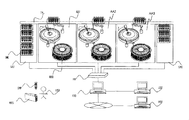
- FIG. 1 is a system configuration diagram showing an entire configuration of an automatic analyzer according to an embodiment of the present invention.
- the automatic analyzer includes, for example, three analyzers AA1, AA2, and AA3 arranged in series.
- the number of analysis units is not limited to three, and may be plural or singular.
- a transport line TRL for transporting a sample rack is provided adjacent to each analysis unit AA1, AA2, AA3.
- the sample loading unit SAI is provided on one end side of the analysis units AA1, AA2, AA3 arranged in series, and the sample storage unit SAO is provided on the other end.
- the user USR loads the sample SMP, which is the target of calibration measurement, quality control sample measurement, and patient sample measurement, in the sample rack SML.
- a plurality of samples can be mounted on the sample rack SML.
- the sample rack SML loaded with the sample is placed in the sample insertion unit SAI.
- the installed sample racks SML are sequentially carried into the transport line 305, and transported to the analysis units AA1, AA2, and AA3 that analyze the samples.
- the analysis units AA1, AA2, and AA3 respectively recognize the sample rack SML and the sample SMP, and perform analysis necessary for the sample SMP.
- Each of the analysis units AA1, AA2, and AA3 includes a reagent disk RED that stores a plurality of reagents REG used to perform the analysis.
- the reagent REG required for analysis is placed on the reagent disc RED prior to analysis by the user.
- the sample rack SML for which the necessary analysis has been performed is transported to the sample storage unit SAO.
- the sample loading unit SAI, the analysis units AA1, AA2, and AA3, and the sample storage unit SAO are each connected to the operation unit PC100 of the automatic analyzer via the hub HB with a network cable.
- the operation unit PC 100 is connected to the upper host system USY via a network.
- the user makes an analysis request (measurement request) for each sample from the host system USY or the operation unit PC 100, mounts the sample to be analyzed in the sample rack SML, and installs the sample in the sample loading unit SAI.
- the information requested for analysis is transmitted to the analysis units AA1, AA2 and AA3 via the network, and the analysis results of the analysis units AA1, AA2 and AA3 are transmitted to the operation unit PC100 and the upper host system USY.
- the operation unit PC100 is connected to the remote system RSY via a public line.
- the remote system RSY stores information such as analysis parameters which is analysis condition information using a reagent used in the automatic analyzer, and distributes analysis parameters in response to a request from the operation unit PC 100.
- the distributed analysis parameters are stored in the operation unit PC100, and transmitted to the analysis units AA1, AA2, and AA3 at the time of analysis of the sample.
- the operation unit PC100 is in charge of the work schedule information inputted by the upper host system USY which is the upper system of the operation unit PC100 or the automatic analysis apparatus or the remote system RSY and the work event information of the device managed by the operation unit PC100. Create work schedule information for each person.
- the user can confirm the work that he / she must perform on the work schedule screen displayed on the operation unit PC 100, and can make an efficient work plan in accordance with the work schedule.
- the work schedule management unit is provided on the upper host system or remote system that is the upper system according to the user's usage pattern, and the information is transmitted / received to / from the operation unit PC and analysis unit via the network good.
- FIG. 2 is a block diagram showing the configuration of the operation unit PC used in the automatic analyzer according to one embodiment of the present invention.
- the operation unit PC 100 mainly includes a control unit 110, an input unit 120, a display unit 130, and a storage unit 140.
- the input unit 120 includes a keyboard and a mouse.
- the display of the button displayed on the display unit 130 can be pressed down (clicked with the mouse), or numbers and characters can be input to the input frame displayed on the display unit 130 from the keyboard.
- a GUI Graphic User Interface
- the control unit 110 includes a planning unit 112, a schedule creation unit 113, a notification unit 114, a reservation unit 116, and a determination unit 118. These functions and operations will be described later.
- the storage unit 140 stores the work schedule information and the work event information described above.
- the planning unit 112 uses this information to plan a work schedule.
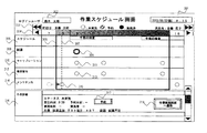
- FIG. 3 is an explanatory diagram of an example of a work schedule screen in the automatic analyzer according to one embodiment of the present invention.
- the work schedule screen 301 is displayed on the display unit 130 of FIG.
- the work schedule screen 301 displays, as a time schedule, a list of work that the user who has logged in to the operation unit PC 100 has to perform within the assigned time.
- the initial display of the work schedule screen 301 is optimized for the work user by centering the work schedule of the login user in the relevant time zone.
- the charge back and forth movement button 303 is a button for displaying the work schedule of the person in charge before and the person in charge after the login user.
- the time back and forth movement button 304 is a button for scrolling the display of the work schedule on an hourly basis.
- the schedule display area 305 displays the schedule of the hospital or the examination room.
- the reagent operation display area 308 displays a reagent operation event 309 such as reagent addition accompanying reagent shortage.
- the calibration operation display area 310 displays a calibration operation event 311 such as calibration measurement accompanying reagent addition or timeout.
- the quality control work display area 312 displays a quality control work event 313 such as quality control measurement associated with reagent addition and time-out.
- the maintenance operation display area 314 displays a maintenance operation event 315 such as maintenance execution accompanying a timeout or parts replacement. It is preferable to improve the visibility of each work event by changing the mark depending on the work situation.
- the time slot 306 for the logged-in user and the current time line 307 are displayed.
- the person in charge can easily confirm the work to be performed within the assigned time, and it is possible to confirm at what timing the work will occur with respect to the schedule of the hospital or examination room, efficiently It can be judged whether it can work.
- the type of work event displayed on this screen As the type of work event displayed on this screen, as shown in the screen example, it is best to set it as the work related to the most important reagent for guaranteeing the performance as an automatic analyzer, calibration, accuracy control, and maintenance, It is desirable to be customizable according to the purpose of the user who uses it.
- the reagent operation event 309, the calibration operation event 311, the quality control operation event 313, etc. will occur during the inspection in the afternoon, and know that the morning inspection may be interrupted.
- the maintenance work event 315 displays the dotted circle and the solid circle connected by an arrow, and represents the work carried forward by the login user because the person in charge has not performed the work.
- the work detail display area 316 displays the details of the work event selected on the screen.
- the reagent operation event 309 is in a state of being selected.
- the reagent operation event 309 in the reagent operation display area 308 is surrounded by a thick circle, which indicates, for example, a selected state.
- the color of the circle mark of the selected event or the like is changed to indicate that it is selected.
- the work detail area 316 displays the work execution status, the occurrence time, the reservation time, the execution time, the implementer and the work content.
- a work reservation button 317 is provided for reserving work at a convenient time in advance when the occurrence time is inconvenient on the schedule.
- the work execution screen transition button 318 the screen can be directly transitioned to each work execution screen for performing the work, and the work can be performed promptly.
- the user can confirm the work to be performed within the assigned time, and can make an efficient work plan.
- the work schedule screen 301 when the user logs out from the operation unit PC 100, the user can check whether there is nothing forgotten about the work to be performed within the assigned time. .
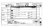
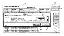
- FIG. 4 is an explanatory diagram of an example of a work schedule screen after work execution and reservation in the automatic analyzer according to the embodiment of the present invention.
- the user performed each operation prior to the morning inspection with respect to the reagent operation event 402, the calibration operation events 404 and 405, the quality control operation events 408 and 409, and the maintenance operation event 411.
- the reagent work event 401, the calibration work event 403, the quality control work event 407, the maintenance work event 411, and the work detail display area 413 are displayed as the work completed state.
- connections and broken lines are displayed so that the relationship with the work events 402, 404, 405, 408, and 409 displayed at the original occurrence time can be understood. That is, the work indicated by the broken circle (for example, the work event 402) is displayed as the black circle work that has been performed (for example, the work event 401), and both are connected by the broken arrow.
- the calibration work event, the quality control work event, and the maintenance work event can be performed prior to the afternoon inspection so that the occurrence of the work can be foreseen during the afternoon inspection.
- performing the work of the next person in charge time in advance reduces the work load of the next person in charge considering that the next person in charge is a person inexperienced in the apparatus. You can expect effects such as
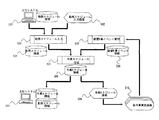
- FIG. 5 is an explanatory diagram of a data flow relating to a work schedule management function in the automatic analyzer according to one embodiment of the present invention.
- work schedule information 504 is created by receiving from the upper system USY connected via the network or by inputting from the work schedule input screen 502 of the operation unit PC 100.
- work event information 506 related to parameters registered in the device, reagent information and measurement, reagents predicted to be generated from the results of maintenance, calibration, accuracy management, and maintenance are created, to manage.
- work schedule information 508 for each person in charge is created based on the work schedule information 504 and the device work event information 506.
- the created work schedule information 508 is displayed on the work schedule screen 509. Also, the work schedule information 508 is transmitted to the upper system USY connected by the network.
- the user confirms the work on the work schedule screen, transitions to the work execution screen 510, and executes each work.
- the executed work event is fed back to the apparatus work event management process 505, and the work event information 506 is updated.
- the planning unit 112 in FIG. 2 plans in advance a work event required to use the apparatus, and performs the apparatus work event management process 505 in FIG. 5.
- the schedule creating unit 113 of FIG. 2 creates a time-series work schedule table as a list of tasks to be performed by the user within the assigned time, from the work schedule and the work events. It is something to do.
- the notification unit 114 in FIG. 2 urges the user to work when the reserved time is reached, and notifies the user on a work notification dialog screen 904 described later with reference to FIG.
- the reservation unit 116 in FIG. 2 is for the user to set an arbitrary scheduled operation time for the work event on the work schedule, and is inputted by the worker when the work reservation button 317 in FIG. 3 is depressed. Data is set.
- the determination unit 118 in FIG. 2 recognizes the work performed on the device, and automatically determines whether the work event displayed in the work schedule table has been performed or not, and the device work event management in FIG. 5 is performed. Process 505 is performed.
- the input unit 120 of FIG. 2 is for inputting the work schedule of the user using the apparatus, and as described above, constitutes a GUI together with the display unit 130 for displaying the presence or absence of work execution on the work schedule table.
- the work schedule information 504, the work event information 506, and the work schedule information 508 in FIG. 5 are stored in the storage unit 140 shown in FIG.
- the schedule table creation unit 113 creates a time-series work schedule table as a list of tasks that the user should perform within the assigned time from the work schedule and the work events.
- the created work schedule table is displayed on, for example, the work schedule screen 301 of FIG.
- the work implementation screen transition button 318 is pressed down. Thereby, the procedure for the reagent addition operation is displayed on the display screen of the display unit 130.
- the person in charge proceeds with the reagent addition operation, and when the reagent addition is completed, for example, when the button of “end of reagent addition” is displayed on the display unit 130, the schedule table creation unit 113 Recognize that the work has been completed.
- the schedule table creation unit 113 recognizes that the work has not been performed until the button of “end of reagent addition” is pressed.
- the determination as to whether the work has not been performed is performed by the determination unit 118 shown in FIG.
- the maintenance person to be performed represented by the maintenance operation display area 314 in FIG.
- the maintenance work that has not been performed is displayed on the work schedule screen 301 of FIG. 3 as the maintenance work event 315 of the person in charge.
- the work execution screen transition button 318 is depressed, and the reagent is displayed according to the procedure for the reagent addition work displayed on the display screen of the display unit 130
- the button of “end of reagent addition” displayed on the display unit 130 is pushed down.
- the work event information 506 is updated on the assumption that the reagent addition work is completed.
- the schedule table creation unit 113 can recognize that the work has been completed by referring to the work event information 506 by the work schedule creation processing 507, and is displayed on the work schedule screen 301 as the completed work event 401 in FIG. Ru.
- the calibration work event 406 is selected when the work is reserved before the inspection in the afternoon. Then, the details are displayed as shown in the work detail display area 316 of FIG. Then, the person in charge enters, for example, “8:30” in the “reservation time” column, and presses the reservation button 317 to change the reservation time after the change by the device work event management process 505 in FIG.
- the work event information 506 is updated to
- the schedule table creation unit 113 displays the work schedule after the change on the work schedule screen 301 as in the calibration work event 406 of FIG. 4 by referring to the work event information 506 by the work schedule creation processing 507. .
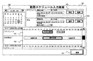
- FIG. 6 is an explanatory diagram of an example of a work schedule input screen in the automatic analysis device according to one embodiment of the present invention.
- the work schedule input screen 601 is a screen for a user at the manager level to register a daily inspection schedule and assignment of persons in charge. This screen is implemented on the operation unit PC of the automatic analyzer or on a host system connected via a network. In the case of a large hospital or laboratory, the number of apparatuses used is large and the number of persons in charge is also large, so it is efficient and preferable to implement and integrally manage in a higher system.
- the calendar 602 is used to select the inspection schedule and the date to which the assignee is assigned. A time is specified in the schedule input area 603 for the selected date, and a schedule is input. The input schedule is displayed in the schedule display area 605.
- a time is designated in the assigned input area 604, and a responsible person is input.
- the assignment of the input person in charge is displayed in the assignment assignment display area 606.
- the input schedule and assignment information of the person in charge are stored by pressing the registration button 607.
- this screen is implemented in the upper system, a plurality of devices are to be managed, and therefore, the information for identifying the devices is added, and the screen layout is such that the schedule input for each device is performed.
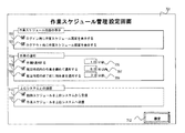
- FIG. 7 is an explanatory diagram of an example of a work schedule management setting screen in the automatic analyzer according to one embodiment of the present invention.
- the work schedule management setting screen 701 is a screen for performing settings such as screen display in the work schedule management function, work notification, and communication with the upper system.
- the log-in work schedule display setting column 702 is used to set whether or not to automatically display a work schedule screen of the logged-in user when the user logs in to the system on the operation unit PC.
- the work schedule display setting column 703 is used to set whether or not to automatically display the work schedule screen of the login user when the user logs out of the system.
- the user can confirm the work schedule that he / she must perform within the assigned time when logging in to the system, and can make an efficient work plan. it can. Also, when logging out of the system, it can be confirmed that there is no work omission.
- the work notification setting field 704 is used to set whether or not to display a notification for prompting the user to work when the time of occurrence of each work event or when the user has made a reservation is reached.
- Be The work notification time setting field 705 is a setting of a time for performing work notification in advance.
- the combined work notification setting column 706 and the combined work notification time setting column 707 recommend that when a certain work event reaches the work time, the work time to arrive within the specified time starting from that time be collectively implemented It is used to set whether or not to display a notification.
- the work notification before completion of work time setting column 708 and the work notification time before completion of work time setting column 709 are used for setting to notify the remaining work before the specified time of completion of the work time.
- the notified time is managed by the notification unit 114 shown in FIG.
- the notification unit 114 notifies the user on the work notification dialog screen 904 described later with reference to FIG.
- the work schedule upper system reception setting column 710 sets whether or not work schedule information necessary for creating work schedule information is received from a higher system connected via a network.
- the work schedule upper system transmission setting field 711 sets whether to transmit the created work schedule information to the upper system.
- the information input on this screen is saved by pressing the setting button 712.
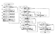
- FIG. 8 is a flowchart showing the contents of work schedule creation and management processing in the automatic analyzer according to one embodiment of the present invention.
- step 801 it is determined whether there is a work schedule reception setting from the host system. If there is a setting, work schedule information is received from a host system connected via a network at step 802.
- step 803 work schedule information is read. If the setting is not made at step 801, the work schedule information registered on the work schedule input screen on the operation unit PC is read.
- step 804 the apparatus operation event information on parameters registered in the apparatus, information and measurement of the reagent, reagents predicted to be generated from the results of maintenance, maintenance, calibration, quality control, and maintenance is read.
- step 805 based on the work schedule information read at step 803, the apparatus work event information read at step 804 is incorporated to create a work schedule for each person in charge. This is the process of creating a work schedule.
- step 806 it is determined whether there is a work event that has reached the notification time. If there is a work event, it is determined in step 807 whether there is a work event that reaches the notification time within the specified time. If there is, the user is notified in step 808 to perform the corresponding work collectively. If not, the user is notified in step 809 to carry out the work individually.
- the time of addition of the reagent is determined by the remaining amount of each reagent, and therefore, is different from each other.
- a second reagent addition work event is scheduled to occur 10 minutes after the first reagent addition work event, secondly following the first reagent addition.
- the addition of reagents saves the trouble of adding reagents. In such a case, it is considered appropriate to carry out the work collectively.
- calibration is generally performed at regular intervals in consideration of deterioration of the reagent.
- quality control is generally performed each time measurement of a predetermined number of samples is performed. If calibration and accuracy control for a given reagent are scheduled at a slightly separated timing, it is more efficient to perform this sequentially. In such cases, it is considered appropriate to carry out the work collectively.
- step 810 it is determined whether or not the set time for termination of the assigned time is over. If it does, the user is notified in step 811 to carry out the work with the unexecuted work event within the assigned time as the remaining work.
- step 812 it is determined whether there is an operation that could not be performed within the assigned time. In some cases, the remaining work is carried over to the work schedule of the next person in charge in step 813.
- step 814 it is determined whether there is a work schedule transmission setting to the upper system, and if there is, work schedule information is transmitted to the upper system in step 815.
- FIG. 9 is an explanatory diagram of an example of a work notification dialog screen in the automatic analyzer according to one embodiment of the present invention.
- FIG. 8 shows the case where the task notification dialog screen 904 is displayed while the user is using the patient sample measurement result screen 901.
- the task notification dialog screen 901 displays the content of the task for prompting execution in the task detail display area 905. If there are multiple tasks, they will be displayed in a list format. By pressing the work execution screen transition button 906 displayed for each work, the screen can be directly transitioned to each work execution screen for performing the corresponding work, and the work can be performed promptly.
- the work schedule screen transition button 903 is a button for displaying a work schedule screen. It is preferable that this button is arranged in the global non-screen dependent display area 902 which does not depend on the display of each screen so that the work schedule screen can be displayed from any screen.
- a list of tasks to be performed within the assigned time may be displayed.
- the user can confirm the work at the start of the work, and can make an efficient work plan according to the work schedule.
- the work schedule to be performed by the user within the assigned time can be integrated and managed across multiple devices, and the burden on the user can be alleviated and the work schedule can be efficiently managed in a large-scale inspection facility.
- reagent work display area 309 ... reagent work event 310 ... calibration work display area 311 . calibration work event 312 ... quality control work display area 13 ... Accuracy management work event 314 ... Maintenance work display area 315 ... Maintenance work event 316 ... Work detail display area 317 ... Work reservation button 318 ... Work execution screen transition button 401, 402 ... Reagent work event 403 to 406 ... Calibration work event 407-410 ... Quality control work event 411, 412 ... Maintenance work event 413 ... Work detail display area 502 ... Work schedule input screen 503 ... Work schedule input processing 504 ... Work schedule information 505 ... Equipment work event management processing 506 ... Equipment work event Information 507 ... Work schedule creation process 508 ...
- Flow chart step 901 ... Patient sample measurement result screen 902 ... Non-screen dependent display area 903 ... Work schedule screen transition button 904 ... Work notification Dialog screen 905 ... Work details display area 906 . Work implementation screen transition button 907 ... Work schedule screen transition button 908 ... Close button
Landscapes
- Business, Economics & Management (AREA)
- Human Resources & Organizations (AREA)
- Engineering & Computer Science (AREA)
- General Business, Economics & Management (AREA)
- Health & Medical Sciences (AREA)
- Economics (AREA)
- Entrepreneurship & Innovation (AREA)
- Strategic Management (AREA)
- Physics & Mathematics (AREA)
- General Physics & Mathematics (AREA)
- Biomedical Technology (AREA)
- General Health & Medical Sciences (AREA)
- Theoretical Computer Science (AREA)
- Development Economics (AREA)
- Quality & Reliability (AREA)
- Operations Research (AREA)
- Marketing (AREA)
- Game Theory and Decision Science (AREA)
- Tourism & Hospitality (AREA)
- Educational Administration (AREA)
- Epidemiology (AREA)
- Medical Informatics (AREA)
- Primary Health Care (AREA)
- Public Health (AREA)
- Analytical Chemistry (AREA)
- Biochemistry (AREA)
- Chemical & Material Sciences (AREA)
- Immunology (AREA)
- Pathology (AREA)
- Life Sciences & Earth Sciences (AREA)
- Automatic Analysis And Handling Materials Therefor (AREA)
- Management, Administration, Business Operations System, And Electronic Commerce (AREA)
Priority Applications (3)
| Application Number | Priority Date | Filing Date | Title |
|---|---|---|---|
| CN201380054522.3A CN104737186B (zh) | 2012-10-25 | 2013-10-22 | 自动分析装置 |
| US14/436,097 US20150269513A1 (en) | 2012-10-25 | 2013-10-22 | Automatic analyzer |
| EP13848657.6A EP2913787B1 (en) | 2012-10-25 | 2013-10-22 | Automatic analysis device |
Applications Claiming Priority (2)
| Application Number | Priority Date | Filing Date | Title |
|---|---|---|---|
| JP2012-235606 | 2012-10-25 | ||
| JP2012235606A JP6180721B2 (ja) | 2012-10-25 | 2012-10-25 | 自動分析装置 |
Publications (1)
| Publication Number | Publication Date |
|---|---|
| WO2014065277A1 true WO2014065277A1 (ja) | 2014-05-01 |
Family
ID=50544656
Family Applications (1)
| Application Number | Title | Priority Date | Filing Date |
|---|---|---|---|
| PCT/JP2013/078576 Ceased WO2014065277A1 (ja) | 2012-10-25 | 2013-10-22 | 自動分析装置 |
Country Status (5)
| Country | Link |
|---|---|
| US (1) | US20150269513A1 (enExample) |
| EP (1) | EP2913787B1 (enExample) |
| JP (1) | JP6180721B2 (enExample) |
| CN (1) | CN104737186B (enExample) |
| WO (1) | WO2014065277A1 (enExample) |
Cited By (1)
| Publication number | Priority date | Publication date | Assignee | Title |
|---|---|---|---|---|
| CN107407686A (zh) * | 2015-03-02 | 2017-11-28 | 株式会社日立高新技术 | 自动分析装置 |
Families Citing this family (11)
| Publication number | Priority date | Publication date | Assignee | Title |
|---|---|---|---|---|
| SG11201708172RA (en) * | 2015-04-07 | 2017-11-29 | Tlv Co Ltd | Maintenance support system and maintenance support method |
| US10984363B2 (en) * | 2015-09-04 | 2021-04-20 | International Business Machines Corporation | Summarization of a recording for quality control |
| JP6647939B2 (ja) * | 2016-03-28 | 2020-02-14 | キヤノンメディカルシステムズ株式会社 | 自動分析装置 |
| EP3517968B1 (en) * | 2016-09-21 | 2022-11-09 | Hitachi High-Tech Corporation | Automated analysis device |
| CN107356775B (zh) * | 2017-07-03 | 2020-04-14 | 苏州卫宁精密仪器设备有限公司 | 一种用于化学发光免疫分析的测试任务规划方法 |
| EP3474018B1 (en) | 2017-10-18 | 2020-07-22 | Roche Diagnostics GmbH | A method to store sample tubes in a laboratory storage and retrieval system |
| JP6824945B2 (ja) * | 2018-11-30 | 2021-02-03 | シスメックス株式会社 | 検体分析装置および検体分析方法 |
| CN110957026B (zh) * | 2019-12-16 | 2023-08-01 | 国康生物工程(深圳)有限公司 | 医疗设备运行环境的调节方法、终端和存储介质 |
| CN115088000A (zh) * | 2020-03-05 | 2022-09-20 | 株式会社日立高新技术 | 管理装置和委托方法 |
| JP7443190B2 (ja) * | 2020-08-18 | 2024-03-05 | 株式会社日立ハイテク | 自動分析装置 |
| US20240175884A1 (en) * | 2022-11-30 | 2024-05-30 | Artificial, Inc. | Automated labratory scheduling based on user-drawn workflow |
Citations (10)
| Publication number | Priority date | Publication date | Assignee | Title |
|---|---|---|---|---|
| JP2002083101A (ja) * | 2000-09-07 | 2002-03-22 | Hitachi Building Systems Co Ltd | 保守巡回作業表作成装置 |
| JP2003256384A (ja) * | 2002-02-27 | 2003-09-12 | Hitachi Ltd | 予定情報管理方法およびシステム、プログラム、ならびにそれを記録した記録媒体 |
| JP2004094511A (ja) * | 2002-08-30 | 2004-03-25 | Ishikawajima Plant Construction Co Ltd | 建設工事進捗管理システム |
| JP2006004021A (ja) * | 2004-06-15 | 2006-01-05 | Toyo Eng Corp | スケジュール作成支援システム、装置、プログラム、および方法 |
| JP2006053164A (ja) | 1997-04-10 | 2006-02-23 | Hitachi Ltd | 自動分析装置およびその支援システム |
| JP2006338485A (ja) * | 2005-06-03 | 2006-12-14 | Hitachi Medical Corp | 看護支援システム |
| JP2007241393A (ja) * | 2006-03-06 | 2007-09-20 | Hitachi Electronics Service Co Ltd | スケジュール割当てシステム及び作業スケジュール割当てプログラム及び作業スケジュール割当て方法 |
| JP2008059523A (ja) * | 2006-09-04 | 2008-03-13 | Hitachi Electronics Service Co Ltd | スケジュール管理システム及びスケジュール管理情報処理装置及びスケジュール管理プログラム及びスケジュール管理方法 |
| JP2008066633A (ja) * | 2006-09-11 | 2008-03-21 | Hitachi High-Technologies Corp | 欠陥検査解析システム、欠陥検査解析方法及びこれに用いる管理コンピュータ |
| JP2011022734A (ja) * | 2009-07-15 | 2011-02-03 | Fujitsu Ltd | 情報処理装置 |
Family Cites Families (17)
| Publication number | Priority date | Publication date | Assignee | Title |
|---|---|---|---|---|
| WO1993003347A1 (en) * | 1991-07-26 | 1993-02-18 | Cirrus Diagnostics, Inc. | Automated immunoassay analyzer |
| JP2988362B2 (ja) * | 1996-03-11 | 1999-12-13 | 株式会社日立製作所 | 多検体分析システム |
| JP3643478B2 (ja) * | 1997-05-19 | 2005-04-27 | 株式会社東芝 | 制御システム |
| US6633782B1 (en) * | 1999-02-22 | 2003-10-14 | Fisher-Rosemount Systems, Inc. | Diagnostic expert in a process control system |
| US6954737B2 (en) * | 2001-11-05 | 2005-10-11 | Johnsondiversey, Inc. | Method and apparatus for work management for facility maintenance |
| US7850912B2 (en) * | 2003-05-14 | 2010-12-14 | Dako Denmark A/S | Method and apparatus for automated pre-treatment and processing of biological samples |
| US7185288B2 (en) * | 2003-07-18 | 2007-02-27 | Dade Behring Inc. | Operator interface module segmented by function in an automatic clinical analyzer |
| EP1892531B1 (en) * | 2006-08-22 | 2017-04-05 | Sysmex Corporation | Sample analyzer |
| JP4977634B2 (ja) * | 2008-01-18 | 2012-07-18 | 株式会社日立ハイテクノロジーズ | 自動分析装置 |
| JP2009270841A (ja) * | 2008-04-30 | 2009-11-19 | Hitachi High-Technologies Corp | 自動分析装置 |
| US9229015B2 (en) * | 2008-12-26 | 2016-01-05 | Hitachi High-Technologies Corporation | Accuracy management method |
| JP5286134B2 (ja) * | 2009-03-31 | 2013-09-11 | 株式会社日立ハイテクノロジーズ | 検体検査システムとその装置管理サーバの運用方法 |
| EP2454000A4 (en) * | 2009-07-17 | 2016-08-10 | Ibis Biosciences Inc | SYSTEMS FOR IDENTIFYING BIOLOGICAL SUBSTANCES |
| US20110112877A1 (en) * | 2009-11-09 | 2011-05-12 | Nirmal Govind | Method and Apparatus for Constraint-based Staff Scheduling |
| JP5875750B2 (ja) * | 2010-05-07 | 2016-03-02 | 株式会社東芝 | 自動分析装置 |
| JP5600487B2 (ja) * | 2010-06-24 | 2014-10-01 | シスメックス株式会社 | 検体分析装置及び液体吸引方法 |
| JP2013217741A (ja) * | 2012-04-06 | 2013-10-24 | Hitachi High-Technologies Corp | 自動分析装置 |
-
2012
- 2012-10-25 JP JP2012235606A patent/JP6180721B2/ja active Active
-
2013
- 2013-10-22 CN CN201380054522.3A patent/CN104737186B/zh active Active
- 2013-10-22 US US14/436,097 patent/US20150269513A1/en not_active Abandoned
- 2013-10-22 WO PCT/JP2013/078576 patent/WO2014065277A1/ja not_active Ceased
- 2013-10-22 EP EP13848657.6A patent/EP2913787B1/en active Active
Patent Citations (10)
| Publication number | Priority date | Publication date | Assignee | Title |
|---|---|---|---|---|
| JP2006053164A (ja) | 1997-04-10 | 2006-02-23 | Hitachi Ltd | 自動分析装置およびその支援システム |
| JP2002083101A (ja) * | 2000-09-07 | 2002-03-22 | Hitachi Building Systems Co Ltd | 保守巡回作業表作成装置 |
| JP2003256384A (ja) * | 2002-02-27 | 2003-09-12 | Hitachi Ltd | 予定情報管理方法およびシステム、プログラム、ならびにそれを記録した記録媒体 |
| JP2004094511A (ja) * | 2002-08-30 | 2004-03-25 | Ishikawajima Plant Construction Co Ltd | 建設工事進捗管理システム |
| JP2006004021A (ja) * | 2004-06-15 | 2006-01-05 | Toyo Eng Corp | スケジュール作成支援システム、装置、プログラム、および方法 |
| JP2006338485A (ja) * | 2005-06-03 | 2006-12-14 | Hitachi Medical Corp | 看護支援システム |
| JP2007241393A (ja) * | 2006-03-06 | 2007-09-20 | Hitachi Electronics Service Co Ltd | スケジュール割当てシステム及び作業スケジュール割当てプログラム及び作業スケジュール割当て方法 |
| JP2008059523A (ja) * | 2006-09-04 | 2008-03-13 | Hitachi Electronics Service Co Ltd | スケジュール管理システム及びスケジュール管理情報処理装置及びスケジュール管理プログラム及びスケジュール管理方法 |
| JP2008066633A (ja) * | 2006-09-11 | 2008-03-21 | Hitachi High-Technologies Corp | 欠陥検査解析システム、欠陥検査解析方法及びこれに用いる管理コンピュータ |
| JP2011022734A (ja) * | 2009-07-15 | 2011-02-03 | Fujitsu Ltd | 情報処理装置 |
Non-Patent Citations (1)
| Title |
|---|
| See also references of EP2913787A4 |
Cited By (2)
| Publication number | Priority date | Publication date | Assignee | Title |
|---|---|---|---|---|
| CN107407686A (zh) * | 2015-03-02 | 2017-11-28 | 株式会社日立高新技术 | 自动分析装置 |
| EP3267202A4 (en) * | 2015-03-02 | 2018-10-17 | Hitachi High-Technologies Corporation | Automatic analysis device |
Also Published As
| Publication number | Publication date |
|---|---|
| CN104737186B (zh) | 2018-10-26 |
| CN104737186A (zh) | 2015-06-24 |
| EP2913787B1 (en) | 2021-09-29 |
| JP6180721B2 (ja) | 2017-08-16 |
| EP2913787A1 (en) | 2015-09-02 |
| EP2913787A4 (en) | 2016-09-07 |
| US20150269513A1 (en) | 2015-09-24 |
| JP2014085270A (ja) | 2014-05-12 |
Similar Documents
| Publication | Publication Date | Title |
|---|---|---|
| WO2014065277A1 (ja) | 自動分析装置 | |
| JP5753792B2 (ja) | 自動分析装置 | |
| EP2249272B1 (en) | Analysis system for analyzing biological samples | |
| EP3422015B1 (en) | Automated analysis device | |
| EP2975559B1 (en) | Method and system for aggregating diagnostic analyzer related information | |
| US11340243B2 (en) | Automated analysis system | |
| WO2005101023A1 (en) | Method and system for drug screening | |
| JP6689852B2 (ja) | 調査実績フレームワーク | |
| JP2011064682A (ja) | 生体サンプルの分析システム、方法及びコンピュータプログラム製品 | |
| US12027265B2 (en) | Method and systems for integrated alert management | |
| Fung | Utilizing connectivity and data management system for effective quality management and regulatory compliance in point of care testing | |
| US11416064B2 (en) | Alerts with augmented reality | |
| JP6282513B2 (ja) | 検査結果解析支援システム | |
| EP3341927B1 (en) | Command center | |
| JP2005351777A (ja) | 分析システム | |
| Yun et al. | Efficiency of an automated reception and turnaround time management system for the phlebotomy room | |
| Hauglid | A web-based dashboard to facilitate progress management of pathology workflows | |
| Alahmri et al. | THE ROLE OF AUTOMATION IN MODERN CLINICAL LABORATORIES | |
| CN116414275A (zh) | 任务显示排布方法、装置、计算设备和样本分析仪 | |
| Lone et al. | Microbiology laboratory consolidation: Optimizing diagnostic efficiency and service quality—A case study from Dubai Health, United Arab Emirates | |
| EP4099304A1 (en) | Customized laboratory training based on user role and laboratory configuration | |
| Kim Futrell et al. | Clinisys™ Laboratory Solution Our cloud-based software is configurable for both sample-centric and patient-centric workflows. Whether you need a configurable SaaS laboratory information management system (LIMS) or a laboratory information system (LIS) Clinisys Laboratory Solution can advance your lab informatics capabilities in and beyond the lab, drive digital transformation and unlock the power of data. | |
| Olla et al. | BPH laboratories: a proof-of-concept case on integrating smartphone diagnostics into clinical systems | |
| Bernard et al. | Implementation of an integrated instrument control and data management system for point of care blood gas testing | |
| Yun SoonGyu et al. | Efficiency of an automated reception and turnaround time management system for the phlebotomy room. |
Legal Events
| Date | Code | Title | Description |
|---|---|---|---|
| 121 | Ep: the epo has been informed by wipo that ep was designated in this application |
Ref document number: 13848657 Country of ref document: EP Kind code of ref document: A1 |
|
| WWE | Wipo information: entry into national phase |
Ref document number: 2013848657 Country of ref document: EP |
|
| WWE | Wipo information: entry into national phase |
Ref document number: 14436097 Country of ref document: US |
|
| NENP | Non-entry into the national phase |
Ref country code: DE |