WO2014057739A1 - 電力供給装置、電力供給方法およびプログラム - Google Patents
電力供給装置、電力供給方法およびプログラム Download PDFInfo
- Publication number
- WO2014057739A1 WO2014057739A1 PCT/JP2013/073117 JP2013073117W WO2014057739A1 WO 2014057739 A1 WO2014057739 A1 WO 2014057739A1 JP 2013073117 W JP2013073117 W JP 2013073117W WO 2014057739 A1 WO2014057739 A1 WO 2014057739A1
- Authority
- WO
- WIPO (PCT)
- Prior art keywords
- power
- voltage value
- target voltage
- storage device
- power storage
- Prior art date
- Legal status (The legal status is an assumption and is not a legal conclusion. Google has not performed a legal analysis and makes no representation as to the accuracy of the status listed.)
- Ceased
Links
Images


Classifications
-
- B—PERFORMING OPERATIONS; TRANSPORTING
- B66—HOISTING; LIFTING; HAULING
- B66C—CRANES; LOAD-ENGAGING ELEMENTS OR DEVICES FOR CRANES, CAPSTANS, WINCHES, OR TACKLES
- B66C13/00—Other constructional features or details
- B66C13/12—Arrangements of means for transmitting pneumatic, hydraulic, or electric power to movable parts of devices
-
- H—ELECTRICITY
- H02—GENERATION; CONVERSION OR DISTRIBUTION OF ELECTRIC POWER
- H02J—CIRCUIT ARRANGEMENTS OR SYSTEMS FOR SUPPLYING OR DISTRIBUTING ELECTRIC POWER; SYSTEMS FOR STORING ELECTRIC ENERGY
- H02J7/00—Circuit arrangements for charging or depolarising batteries or for supplying loads from batteries
- H02J7/34—Parallel operation in networks using both storage and other DC sources, e.g. providing buffering
Definitions
- the present invention relates to a power supply device, a power supply method, and a program.
- This application claims priority based on Japanese Patent Application No. 2012-224249 filed in Japan on October 9, 2012, the contents of which are incorporated herein by reference.
- a portal crane that is supplied with power from an external power source and that has a power storage device operates various loads such as a traveling motor and a hoisting motor with power from the external power source when the load is low, The power storage device is charged with power from the power source.
- the load when the load is high, such as when lifting a suspended load, the power storage device discharges, and in addition to the power from the external power source, the discharge power from the power storage device is supplied to the load. Since the power storage device supplies power to the load, the maximum value of power supplied from the power source can be reduced, so that the power supply voltage can be lowered.
- the present invention relates to a power supply device, a power supply method, and a program capable of efficiently supplying and supplying power by controlling charging / discharging according to an operation state of a device for a device that uses both power source power and discharge power of a power storage device. provide.
- a power supply device is a power supply device that supplies power to a power load, and converts AC power supplied from a power source into DC power having a first target voltage value and supplies the power to the power load.
- a power conversion device that is connected to the power conversion device in parallel with the power load and that can be charged / discharged, and charge / discharge that controls charging / discharging so that a voltage value of the power storage device becomes a second target voltage value
- a control device, and a target voltage value setting unit that compares a charging rate of the power storage device with a threshold and increases or decreases at least one of the first target voltage value and the second target voltage value according to the comparison result.
- a power supply device is the above-described power supply device, wherein the power load can generate regenerative power, and the threshold value is determined based on a state in which the power storage device is fully charged.
- the target voltage value setting unit is set to be equal to or lower than a charging rate obtained by subtracting the charged amount of electric power, and the second target voltage value is set to the first target voltage value when the charging rate of the power storage device is equal to or higher than the threshold value. At least one of the first target voltage value and the second target voltage value is increased or decreased so as to be larger.
- the power supply device is the above-described power supply device, wherein the target voltage value setting unit is configured to output the second target voltage value when a charge rate of the power storage device is equal to or lower than the threshold value. Is made smaller than the first target voltage value.
- the power supply device is the above-described power supply device, wherein the target voltage value setting unit is configured such that when the charge rate of the power storage device is equal to or lower than the threshold value, the first target voltage value Is made larger than the second target voltage value.
- a power supply device is the above-described power supply device, wherein the power load is a crane device, and the target voltage value setting unit has a power fluctuation of the power load of a predetermined time or more. If not, at least one of charging and discharging of the power storage device is stopped.
- a power supply method that converts AC power supplied from a power source into DC power having a first target voltage value and supplies the power to a power load
- a power supply method for a power supply device comprising: a power storage device connected in parallel with a power load and capable of charging and discharging, wherein charge / discharge is controlled so that a voltage value of the power storage device becomes a second target voltage value
- a charge / discharge control step ; and a target voltage value setting step of comparing the charging rate of the power storage device with a threshold value and increasing or decreasing at least one of the first target voltage value and the second target voltage value according to the comparison result.
- a program for converting AC power supplied from a power source into DC power having a first target voltage value and supplying the power load to the power load ; Charge / discharge control step of controlling charging / discharging so that the voltage value of the power storage device becomes the second target voltage value in a computer that controls the power supply device including the power storage device connected in parallel with the power storage device and a target voltage value setting step of comparing the charging rate of the power storage device with a threshold value and increasing or decreasing at least one of the first target voltage value or the second target voltage value according to the comparison result. is there.
- the power supply device the power supply method, and the program described above, for the device that uses both the power supply and the discharge power of the power storage device, the power supply is efficiently controlled according to the operation status of the device. It can be carried out.
- FIG. 1 is an outline view showing an outline of an outline of a tire type crane (RTG) according to the first embodiment of the present invention.
- a tire type crane system 1 is located on a traveling lane L installed on a road surface R in a container yard Y, and a traveling lane L is obtained by rotating a tire 6a of the traveling mechanism 6 with a traveling motor. Self-propelled above and unloads container C.
- the tire-type crane system 1 includes a crane main body 3 that travels on the road surface R by tires 6a, and a power supply that is a cable that extends from the crane main body 3 and is connected to the ground power supply facility 2 in the travel lane L.
- a cable 4, a cable reel 5 provided on the crane body 3 for winding and unwinding the feeding cable 4, and a box 10 for storing a power supply device, a control device for the crane body 3, and the like are provided.
- the crane body 3 includes the traveling mechanism 6 described above, a pair of leg portions 7 that are erected substantially parallel to each other and that can be traveled by the traveling mechanism 6, a beam portion 8 that is installed between the leg portions 7, and a beam And a suspension mechanism 9 suspended from the portion 8.
- the pair of leg portions 7 support the beam portion 8 and the suspension mechanism 9, and the beam portion 8 supports the suspension mechanism 9 so as to be suspended.
- a guide rail 8 a is provided along the longitudinal direction of the beam portion 8, and the suspension mechanism 9 can travel in the longitudinal direction of the beam portion 8 along the guide rail 8 a.
- the suspension mechanism 9 includes a trolley 9a that can travel along the guide rail 8a of the beam portion 8, a spreader 9b that holds the container C, and a suspension that suspends the spreader 9b from the trolley 9a.
- a rope 9c and a hoisting machine 9d for winding and unwinding the hanging rope 9c are provided.
- the crane body 3 performs the loading and unloading operation of the container C. Specifically, when the spreader 9b grasps the container C, the hoisting machine 9d lifts the container C by hoisting the suspension rope 9c with the power of the hoisting motor. With the container C lifted, the suspension mechanism 9 (trolley 9a) travels in the longitudinal direction of the beam portion 8, and the crane body travels along the travel lane L to move the container C. When the container C moves to the target position, the hoisting machine 9d lowers the container C by returning the winding of the suspension rope 9c.
- the crane main body 3 uses the electric power from the ground power supply facility 2 and the electric power from the power storage device included in the power supply device housed in the box 10 to drive the crane main body 3 and the suspension mechanism.
- Various operations such as running 9 and hoisting of the suspension rope 9c by the hoisting machine 9d are performed.
- a cable-side connector 4 a is provided at the tip of the feeding cable 4 and is connected to the power-side connector 2 a of the ground power supply facility 2.
- the crane body 3 receives power from the ground power supply facility 2 via the power supply cable 4 and supplies power to each part of the crane body 3 through a power supply device housed in the box 10.
- the power supply device controls charging / discharging of the power storage device, and supplies the discharge power of the power storage device to each part of the crane body 3 in addition to the power from the ground power supply facility 2.
- the cable reel 5 winds up the excess of the power supply cable 4 so that the power supply cable 4 is slack and does not hinder the traveling of the crane body 3.
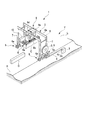
- FIG. 2 is a schematic configuration diagram illustrating a device configuration of the power supply device 100.
- the power supply device 100 includes an AC / DC converter 101, a power storage device 111, a charge / discharge control device 112, and a sequencer 121.
- FIG. 2 also shows the ground power supply facility 2, the power supply cable 4 that connects the ground power supply facility 2 and the power supply device 100, and the load 90 that the power supply device 100 supplies power to.
- the ground power supply facility 2 includes a power supply side connector 2a, a power supply unit 2b, and a transformer 2c.
- the AC power output from the power supply unit 2b is transformed by the transformer 2c and output from the power supply side connector 2a.
- the cable side connector 4a is connected to the power supply side connector 2a, and the power feeding cable 4 supplies the AC power received from the ground power supply facility 2 to the power supply device 100 by the cable side connector 4a.
- the ground power supply facility 2 corresponds to an example of a power supply in the present embodiment.
- the power supply unit 2b may be a power generation facility, or may be a power reception facility that receives a commercial power source or the like, for example.
- the power source in the present embodiment is not limited to an external power source (a power source provided outside the power supply device) such as the ground power source facility 2.
- the power supply apparatus 100 may include a power generator, and the power supply apparatus 100 itself may have a power source.
- the load 90 may be a traveling motor that causes the crane body 3 to travel by rotating the tire 6a (FIG. 1), a hoisting motor that serves as a power source when the hoisting machine 9d winds the suspension rope 9c, or the crane main body 3 It is a general term for the electric power load in the crane main body 3 such as a control device.
- the load 90 can generate regenerative power.
- the traveling mechanism 6 performs regeneration by operating a traveling motor as a regenerative brake when the crane body 3 is braked. Further, when the hoisting machine 9d unwinds the suspension rope 9c and lowers the suspended load, the hoisting machine 9d performs regeneration while operating the hoisting motor as a regenerative brake and adjusting the descending load lowering speed.
- the AC / DC converter 101 converts AC power supplied from the ground power supply facility 2 into DC power having the first target voltage value and supplies the DC power to the load 90.
- the first target voltage value is preset as a fixed voltage value.
- the power storage device 111 includes a secondary battery such as a lead battery or a lithium ion battery, and performs charging and discharging.
- the power storage device 111 is connected to the AC / DC converter 101 in parallel with the load 90 via the charge / discharge control device 112. With this connection relationship, when the voltage value of the power from the AC / DC converter 101 is higher than the voltage value of the power storage device 111, the power storage device 111 is float-charged with the power from the AC / DC converter 101.
- the power storage device 111 includes a BMU (Battery Management Unit), measures the charge rate of the secondary battery, and outputs it to the sequencer 121.
- BMU Battery Management Unit
- the charge / discharge control device 112 controls charging / discharging of the power storage device 111 so that the voltage of the power storage device 111 becomes the second target voltage value.
- the second target voltage value is a variable voltage value set by the sequencer 121.
- Sequencer 121 compares the charging rate of the secondary battery of power storage device 111 (hereinafter simply referred to as “charging rate of power storage device 111”) with a threshold value, and increases or decreases the second target voltage value according to the comparison result.
- the sequencer 121 stores in advance a discharge threshold ShA for switching the power storage device 111 from charging to discharging and a charging threshold ShB for switching the power storage device 111 from discharging to charging.
- the discharge threshold value ShA corresponds to an example of the threshold value in the present embodiment.
- the sequencer 121 corresponds to an example of a target voltage value setting unit in the present embodiment.
- the discharge threshold value ShA is set to be equal to or less than the charging rate obtained by subtracting the regenerative power storage amount from the fully charged state of the power storage device 111.
- the crane main body 3 is braked when the crane main body 3 reaches the container position, and the crane main body 3 when the crane main body 3 reaches the container lowering position. Assume braking and braking of the hoist when the container is lowered. In this case, the total value of the regenerative power expected to be generated by two times of braking of the crane body 3 and one container descent corresponds to the amount of stored regenerative power.
- the maintenance worker of the tire type crane system 1 calculates a charging rate obtained by subtracting the amount of regenerative power stored from the fully charged state, that is, a charging rate that allows for the possibility of charging the regenerative power.
- the maintenance person of the tire type crane system 1 stores the calculated charging rate in the sequencer 121 in advance as the discharge threshold value ShA.
- the maintenance person of the tire-type crane system 1 may store the charge rate obtained by further subtracting the margin considering the battery deterioration from the calculated charge rate as the discharge threshold value ShA in the sequencer 121 in advance. .
- the charging threshold ShB is set to a value smaller than the discharging threshold ShA. If charging threshold ShB ⁇ discharge threshold ShA, power supply device 100 (sequencer 121 and charge / discharge control device 112) can control power storage device 111, but charging is prevented in order to prevent frequent switching of charge / discharge. It is preferable that a dead zone (hysteresis) is provided between the threshold value ShB and the discharge threshold value ShA.
- the power supply device 100 increases the second target voltage value to be larger than the first target voltage value. According to this target voltage value setting, the charge / discharge control device 112 causes the power storage device 111 to discharge. On the other hand, when the charging rate of power storage device 111 becomes equal to or lower than charging threshold ShB, power supply device 100 decreases the second target voltage value to make it smaller than the first target voltage value. According to this target voltage value setting, the charge / discharge control device 112 causes the power storage device 111 to charge.
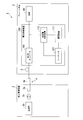
- FIG. 3 is an explanatory diagram showing an example of the target voltage value set by the sequencer 121.
- a line L111 shows an example of the charging rate (State Of Charge; SOC) of the power storage device 111.
- a line L121 indicates an example of the second target voltage value set by the sequencer 121.
- a line L122 indicates an example of an intermediate voltage value between the AC / DC converter 101 and the charge / discharge control device 112.
- the sequencer 121 sets the target voltage value (second target voltage value) of the power storage device 111 to a voltage value Vdset0 that is smaller than the voltage value Vpset that is the output voltage target value (first target voltage value) of the AC / DC converter 101. Is set. Based on this voltage target value setting, charge / discharge control device 112 controls power storage device 111 such that the voltage value of power storage device 111 becomes voltage value Vdset0. As a result, the voltage on the AC / DC converter 101 side becomes higher than the voltage on the power storage device 111 side, and floating charging is performed from the AC / DC converter 101 to the power storage device 111.
- the charging rate of the power storage device 111 is increased by floating charging, and the charging rate reaches the discharge threshold ShA at time T11. Then, the sequencer 121 sets the target voltage value (second target voltage value) of the power storage device 111 to a voltage value Vdset1 that is larger than the voltage value Vpset that is the output voltage target value (first target voltage value) of the AC / DC converter 101. Is set. Based on this voltage target value setting, charge / discharge control device 112 controls power storage device 111 so that the voltage value of power storage device 111 becomes voltage value Vdset1. As a result, the voltage on the power storage device 111 side becomes higher than the voltage on the AC / DC converter 101 side, and the power storage device 111 discharges to the load 90.
- the charging rate of the power storage device 111 decreases due to the discharge, and the charging rate reaches the charging threshold ShB at time T12. Then, the sequencer 121 returns the target voltage value (second target voltage value) of the power storage device 111 to the voltage value Vdset0. Thereby, as before time T11, the voltage on the AC / DC converter 101 side becomes higher than the voltage on the power storage device 111 side, and floating charging is performed from the AC / DC converter 101 to the power storage device 111. In the example of FIG. 3, the power load of the load 90 is in a small state, and the influence of the voltage drop is small. For this reason, the intermediate voltage value indicated by the line L122 is a value between the first target voltage value and the second target voltage value.
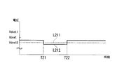
- FIG. 4 is an explanatory diagram showing an example of the intermediate voltage value at the time of high load.
- a line L211 shows an example of the second target voltage value set by the sequencer 121.
- the sequencer 121 continues to set the second target voltage value to a voltage value Vdset0 that is smaller than the first target voltage value.
- a line L212 indicates an example of an intermediate voltage value between the AC / DC converter 101 and the charge / discharge control device 112.
- the load of the load 90 Prior to time T21, the load of the load 90 is in a small state. Thus, floating charging is performed from AC / DC converter 101 to power storage device 111 as in the state before time T11 in FIG. On the other hand, from time T21 to time T22, the power load of the load 90 is in a large state. For this reason, a voltage drop occurs and the intermediate voltage value indicated by the line L212 is smaller than the second target voltage value indicated by the line L211. As a result, the voltage of the power storage device 111 becomes higher than the voltage of the connection destination (particularly the load 90), and the power storage device 111 discharges to the load 90.
- the sequencer 121 sets the second target voltage value to a voltage value smaller than the first target voltage value
- the power storage device 111 discharges to the load 90. Do.
- the maximum value of the power supplied from the ground power supply facility 2 can be reduced, and the power supply voltage can be lowered. Therefore, the voltage value output from the transformer 2c (FIG. 2) can be made relatively small.
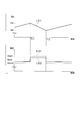
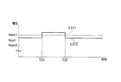
- FIG. 5 is an explanatory diagram illustrating an example of the intermediate voltage value during regeneration.
- a line L311 shows an example of the second target voltage value set by the sequencer 121.
- the sequencer 121 continues to set the second target voltage value to the voltage value Vdset1 that is larger than the first target voltage value.
- a line L312 indicates an example of an intermediate voltage value between the AC / DC converter 101 and the charge / discharge control device 112.
- the load 90 Prior to time T31, the load 90 is not regenerating, and the power storage device 111 is discharging to the load 90 as in the state from time T11 to time T12 in FIG.
- the load 90 is regenerating, the intermediate voltage value indicated by the line L312 is increased by the regenerative power, and the intermediate voltage value is larger than the second target voltage value indicated by the line L311. It has become.
- the voltage of the power storage device 111 becomes lower than the voltage of the connection destination (particularly the load 90), and the power storage device 111 charges regenerative power.
- the power storage device 111 charges the regenerative power.
- the power supply device 100 can efficiently charge and discharge the power storage device 111 in accordance with the operation status of the crane body 3 and supply power to the load 90 in that the regenerative power can be stored without being discarded. Can do.
- the charge / discharge control device 112 controls charging / discharging of the power storage device 111 in anticipation of a margin for charging the regenerative power. Therefore, even if the power storage device 111 charges the regenerative power, overcharge is not caused.
- FIG. 6 is a flowchart showing a processing procedure in which the sequencer 121 sets the second target voltage value.
- the sequencer 121 When the sequencer 121 is connected to its own power supply (ON) and is in an operating state, the sequencer 121 performs the processing shown in FIG.
- the sequencer 121 first initializes the second target voltage value to a voltage value Vdset0 that is smaller than the first target voltage value (step S101).
- the power storage device 111 performs charging, but discharges the load 90 when the load 90 becomes high load.
- sequencer 121 determines whether or not the charging rate of power storage device 111 is equal to or greater than discharge threshold ShA (step S102). When it determines with it being less than discharge threshold value ShA (step S102: NO), it returns to step S102. That is, sequencer 121 waits for the charging rate of power storage device 111 to be equal to or greater than discharge threshold value ShA. On the other hand, when it is determined in step S102 that the charging rate of power storage device 111 is equal to or higher than discharge threshold value ShA (step S102: YES), sequencer 121 sets the second target voltage value to a voltage value larger than the first target voltage value. Vdset1 is set (step S103). In the state where the second target voltage value is the voltage value Vdset1, as described above, the power storage device 111 discharges to the load 90, but when the load 90 regenerates, the regenerative power is charged.
- the sequencer 121 determines whether or not the charging rate of the power storage device 111 is equal to or less than the charging threshold ShB (step S104). When it determines with it being larger than the charging threshold ShB (step S104: NO), it returns to step S104. That is, the sequencer 121 waits for the charging rate of the power storage device 111 to be equal to or less than the charging threshold value ShB. On the other hand, when it is determined in step S104 that the charging rate of the power storage device 111 is equal to or less than the charging threshold ShB (step S104: YES), the sequencer 121 sets the second target voltage value to the voltage value Vdset0 (step S105). . Then, it returns to step S102.
- the charge / discharge control device 112 switches charge / discharge of the power storage device 111 by changing the voltage of the power storage device 111 according to the second target voltage value set by the sequencer 121.
- an instantaneous interruption does not arise. That is, there is no delay in the start of power supply from the power storage device 111 or the delay in the start of charging of the power storage device 111 due to the switch switching operation.
- the power supply device 100 can efficiently control charging / discharging of the power storage device 111 according to the operation state of the crane body 3 and supply power to the load 90.
- the sequencer 121 sets the second target voltage value to a voltage value smaller than the first target voltage value, when the power load of the load 90 increases, the power storage device 111 discharges to the load 90. Thereby, the maximum value of the power supplied from the ground power supply facility 2 can be reduced, and the power supply voltage can be lowered. Therefore, the voltage value output from the transformer 2c (FIG. 2) can be made relatively small.
- the power storage device 111 charges the regenerative power.
- the power supply device 100 can efficiently charge and discharge the power storage device 111 in accordance with the operation status of the crane body 3 and supply power to the load 90 in that the regenerative power can be stored without being discarded. Can do.
- charging / discharging control device 112 controls charging / discharging of power storage device 111 in anticipation of a margin for charging regenerative power. Therefore, even if power storage device 111 charges regenerative power, overcharging does not occur.
- the sequencer 121 can control charging / discharging of the power storage device 111 with a simple configuration in that the charge / discharge of the power storage device 111 can be controlled by setting the target voltage value with reference to only the charging rate of the power storage device 111. can do. Further, in power supply device 100, even when AC / DC converter 101 does not have an output voltage set value switching function, charging / discharging of power storage device 111 can be controlled.
- the charge / discharge control device 112 switches the voltage setting value.
- the following effects can be obtained. That is, when a charge / discharge control device and a power storage device are additionally provided for an electric reel type gate crane without an AC / DC converter mounted power storage device, it is necessary to add an output voltage set value switching function to the AC / DC converter. There is no. In this respect, additional work can be reduced.
- the application range of this invention is not restricted to this.
- the present invention can be applied to various devices that use both power from a power source and power from a power storage device such as a series hybrid hybrid car and a hybrid railway vehicle. The same applies to a second embodiment described later.
- the sequencer 121 may change the target voltage value based on the operation status of the crane body 3. For example, when there is no power fluctuation of the load 90 (both for the winding operation and the traveling operation) within the set time, the charge / discharge control device 112 performs charging or discharging of the power storage device 111 according to the instruction of the sequencer 121. At least one of them may be stopped. When the load power fluctuation is detected, the charge / discharge control device 112 may restore the power storage device 111 to the original state. Thereby, it is possible to avoid unnecessary repetition of charging / discharging operation when there is no load power fluctuation (both for the winding operation and the traveling operation). The same applies to the second embodiment described below.
- FIG. 7 is a schematic configuration diagram showing a device configuration of the power supply device according to the second embodiment of the present invention.
- the power supply device 200 includes an AC / DC converter 201, a power storage device 111, a charge / discharge control device 212, and a sequencer 221.
- FIG. 7 shows the ground power supply facility 2, the power supply cable 4 that connects the ground power supply facility 2 and the power supply device 100, and the load 90 to which the power supply device 100 supplies power.
- the tire crane system 1b differs from the tire crane system 1 (FIG. 2) in that the sequencer 221 changes the first target voltage value instead of the second target voltage value.
- the sequencer 221 increases the first target voltage value to be larger than the second target voltage value when the charging rate of the power storage device 111 becomes equal to or higher than the discharge threshold value ShA.
- the AC / DC converter 201 changes the output voltage value of the AC / DC converter 201 itself according to the first target voltage value set by the sequencer 221.
- the charge / discharge control device 212 controls the charge / discharge of the power storage device 111 by controlling the voltage value of the power storage device 111 based on the second target voltage value.
- the charge / discharge control device 212 differs from the charge / discharge control device 112 in that the second target value is a fixed value.
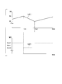
- FIG. 8 is an explanatory diagram illustrating an example of the target voltage value set by the sequencer 221.
- a line L411 indicates an example of a state of charge (SOC) of the power storage device 111.
- a line L421 indicates an example of the first target voltage value set by the sequencer 221.
- the sequencer 221 sets the output voltage target value (first target voltage value) of the AC / DC converter 201 to a voltage value Vpset1 that is larger than the voltage value Vdset that is the target voltage value (second target voltage value) of the power storage device 111. Is set.
- the AC / DC converter 201 controls the AC / DC converter 201 itself so that the output voltage value becomes the voltage value Vpset1. As a result, the voltage on the AC / DC converter 201 side becomes higher than the voltage on the power storage device 111 side, and floating charging is performed from the AC / DC converter 201 to the power storage device 111.
- the charging rate of the power storage device 111 is increased by floating charging, and the charging rate reaches the discharge threshold ShA at time T41. Then, the sequencer 221 sets the output voltage target value (first target voltage value) of the AC / DC converter 201 to a voltage value Vpset0 that is smaller than the voltage value Vdset that is the target voltage value (second target voltage value) of the power storage device 111. Is set. Based on this voltage target value setting, the AC / DC converter 201 controls the AC / DC converter 201 itself so that the output voltage value becomes the voltage value Vpset0. As a result, the voltage on the power storage device 111 side becomes higher than the voltage on the AC / DC converter 201 side, and the power storage device 111 discharges to the load 90.
- the charging rate of the power storage device 111 decreases due to discharging, and the charging rate reaches the charging threshold ShB at time T42. Then, the sequencer 221 returns the output voltage target value (first target voltage value) of the AC / DC converter 201 to the voltage value Vpset1. Thereby, as before time T41, the voltage on the AC / DC converter 201 side becomes higher than the voltage on the power storage device 111 side, and floating charging is performed from the AC / DC converter 201 to the power storage device 111.
- charging / discharging of the power storage device 111 can be switched similarly to the case of the power supply device 100. Even when the load 90 is at a high load, as described with reference to FIG. 4, even when the sequencer 221 sets the first target voltage value to a voltage value larger than the second target voltage value, When the power load of 90 increases, the power storage device 111 discharges to the load 90. Thereby, the maximum value of the power supplied from the ground power supply facility 2 can be reduced, and the power supply voltage can be lowered. Therefore, the voltage value output from the transformer 2c (FIG. 2) can be made relatively small.
- the power storage device 111 charges regenerative power.
- the power supply device 200 can efficiently charge and discharge the power storage device 111 in accordance with the operation status of the crane body 3b and supply power to the load 90 in that the regenerative power can be stored without being discarded. Can do.
- the charge / discharge control device 112 controls the charge / discharge of the power storage device 111 in anticipation of a margin for regenerative power. Therefore, even if the power storage device 111 charges regenerative power, overcharging does not occur.
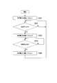
- FIG. 9 is a flowchart showing a processing procedure in which the sequencer 221 sets the first target voltage value.
- the sequencer 221 When the sequencer 221 is connected to its own power supply and enters an operating state, the sequencer 221 performs the processing shown in FIG.
- the sequencer 221 first initializes the first target voltage value to a voltage value Vpset1 that is larger than the second target voltage value (step S201).
- the power storage device 111 performs charging, but discharges the load 90 when the load 90 becomes high load.
- sequencer 221 determines whether or not the charging rate of power storage device 111 is equal to or greater than discharge threshold ShA (step S202). When it determines with it being less than the discharge threshold value ShA (step S202: NO), it returns to step S202. That is, sequencer 221 waits for the charging rate of power storage device 111 to be equal to or greater than discharge threshold value ShA. On the other hand, when it is determined in step S202 that the charging rate of power storage device 111 is equal to or higher than discharge threshold value ShA (step S202: YES), sequencer 221 sets the first target voltage value to a voltage value smaller than the second target voltage value. Vpset0 is set (step S203). In the state where the second target voltage value is the voltage value Vpset0, as described above, the power storage device 111 discharges to the load 90, but when the load 90 regenerates, the regenerative power is charged.
- the sequencer 221 determines whether or not the charging rate of the power storage device 111 is equal to or less than the charging threshold ShB (step S204). When it determines with it being larger than the charging threshold ShB (step S204: NO), it returns to step S204. That is, the sequencer 221 waits for the charging rate of the power storage device 111 to be equal to or lower than the charging threshold ShB. On the other hand, when it is determined in step S204 that the charging rate of the power storage device 111 is equal to or less than the charging threshold ShB (step S204: YES), the sequencer 221 sets the first target voltage value to the voltage value Vpset1 (step S205). . Thereafter, the process returns to step S202.
- the AC / DC converter 201 switches charging / discharging of the power storage device 111 by changing the output voltage value of the AC / DC converter 201 itself according to the first target voltage value set by the sequencer 221.
- an instantaneous interruption does not arise. That is, there is no delay in the start of power supply from the power storage device 111 or the delay in the start of charging of the power storage device 111 due to the switch switching operation.
- the power supply device 200 can efficiently control charging / discharging of the power storage device 111 in accordance with the operation state of the crane body 3b and supply power to the load 90.
- the power storage device 111 discharges to the load 90 when the power load of the load 90 increases. Thereby, the maximum value of the power supplied from the ground power supply facility 2 can be reduced, and the power supply voltage can be lowered. Therefore, the voltage value output from the transformer 2c (FIG. 2) can be made relatively small.
- the power storage device 111 charges regenerative power.
- the power supply device 200 can efficiently charge and discharge the power storage device 111 in accordance with the operation status of the crane body 3b and supply power to the load 90 in that the regenerative power can be stored without being discarded. Can do.
- charging / discharging control device 212 controls charging / discharging of power storage device 111 in anticipation of a margin for charging regenerative power, so that overcharging does not occur even when power storage device 111 charges regenerative power.
- the sequencer 221 can control charging / discharging of the power storage device 111 with a simple configuration in that the charge / discharge of the power storage device 111 can be controlled by setting the target voltage value with reference to only the charging rate of the power storage device 111. can do. Further, in power supply device 200, charging / discharging of power storage device 111 can be controlled even when charging / discharging control device 212 does not have a voltage command value switching function.
- a program for realizing all or part of the functions of the charge / discharge control devices 112 and 212 and the sequencers 121 and 221 is recorded on a computer-readable recording medium, and the program recorded on the recording medium is stored in the computer.
- the processing of each unit may be performed by reading it into the system and executing it.
- the “computer system” includes an OS and hardware such as peripheral devices. Further, the “computer system” includes a homepage providing environment (or display environment) if a WWW system is used.
- the “computer-readable recording medium” refers to a storage device such as a flexible medium, a magneto-optical disk, a portable medium such as a ROM or a CD-ROM, and a hard disk incorporated in a computer system.
- the “computer-readable recording medium” dynamically holds a program for a short time like a communication line when transmitting a program via a network such as the Internet or a communication line such as a telephone line.
- a volatile memory in a computer system serving as a server or a client in that case and a program that holds a program for a certain period of time are also included.
- the program may be a program for realizing a part of the functions described above, and may be a program capable of realizing the functions described above in combination with a program already recorded in a computer system.
- the present invention is a power supply device that supplies power to a power load, wherein the power conversion device that converts AC power supplied from a power source into DC power of a first target voltage value and supplies the power to the power load; and A power storage device connected in parallel with the power load to the power conversion device and capable of charging / discharging, a charge / discharge control device for controlling charge / discharge so that a voltage value of the power storage device becomes a second target voltage value, and the power storage device And a target voltage value setting unit that increases or decreases at least one of the first target voltage value and the second target voltage value according to the comparison result.
- ADVANTAGE OF THE INVENTION According to this invention, with respect to the apparatus which uses power supply electric power and the discharge power of an electrical storage apparatus together, electric power supply can be performed by controlling charging / discharging efficiently according to the operation condition of an apparatus.
Landscapes
- Engineering & Computer Science (AREA)
- Mechanical Engineering (AREA)
- Power Engineering (AREA)
- Charge And Discharge Circuits For Batteries Or The Like (AREA)
Priority Applications (2)
| Application Number | Priority Date | Filing Date | Title |
|---|---|---|---|
| IN649DEN2015 IN2015DN00649A (enExample) | 2012-10-09 | 2013-08-29 | |
| CN201380039016.7A CN104488164B (zh) | 2012-10-09 | 2013-08-29 | 电力供给装置、电力供给方法 |
Applications Claiming Priority (2)
| Application Number | Priority Date | Filing Date | Title |
|---|---|---|---|
| JP2012-224249 | 2012-10-09 | ||
| JP2012224249A JP6196764B2 (ja) | 2012-10-09 | 2012-10-09 | 電力供給装置、電力供給方法およびプログラム |
Publications (1)
| Publication Number | Publication Date |
|---|---|
| WO2014057739A1 true WO2014057739A1 (ja) | 2014-04-17 |
Family
ID=50477212
Family Applications (1)
| Application Number | Title | Priority Date | Filing Date |
|---|---|---|---|
| PCT/JP2013/073117 Ceased WO2014057739A1 (ja) | 2012-10-09 | 2013-08-29 | 電力供給装置、電力供給方法およびプログラム |
Country Status (4)
| Country | Link |
|---|---|
| JP (1) | JP6196764B2 (enExample) |
| CN (2) | CN104488164B (enExample) |
| IN (1) | IN2015DN00649A (enExample) |
| WO (1) | WO2014057739A1 (enExample) |
Families Citing this family (3)
| Publication number | Priority date | Publication date | Assignee | Title |
|---|---|---|---|---|
| JP6575402B2 (ja) * | 2016-03-08 | 2019-09-18 | 株式会社オートネットワーク技術研究所 | 車載電源用の充電率監視装置および車載電源システム |
| CN108306321B (zh) * | 2017-12-20 | 2024-08-23 | 广州智光电气股份有限公司 | 一种储能系统 |
| CN112875518A (zh) * | 2021-01-28 | 2021-06-01 | 三一汽车起重机械有限公司 | 一种起重机多模式插电作业的控制系统及控制方法 |
Citations (6)
| Publication number | Priority date | Publication date | Assignee | Title |
|---|---|---|---|---|
| JPH02237440A (ja) * | 1989-03-07 | 1990-09-20 | Tokyo Electric Power Co Inc:The | 複数電池による直流給電方式 |
| JP2001253653A (ja) * | 2000-03-13 | 2001-09-18 | Hitachi Ltd | エレベータシステム |
| JP2001320893A (ja) * | 2000-05-09 | 2001-11-16 | Mitsubishi Electric Corp | 電動機駆動装置 |
| JP2007209056A (ja) * | 2006-01-31 | 2007-08-16 | Power System:Kk | 蓄電装置 |
| JP2011016635A (ja) * | 2009-07-10 | 2011-01-27 | Tcm Corp | 給電式荷役装置 |
| JP2011135686A (ja) * | 2009-12-24 | 2011-07-07 | Kawasaki Heavy Ind Ltd | ハイブリッドシステムの制御装置及び制御方法 |
Family Cites Families (10)
| Publication number | Priority date | Publication date | Assignee | Title |
|---|---|---|---|---|
| JPH11285165A (ja) * | 1998-03-26 | 1999-10-15 | Sumitomo Heavy Ind Ltd | クレーン用電源設備 |
| EP1235323A4 (en) * | 1999-11-17 | 2008-08-06 | Fujitec Kk | POWER SUPPLY FOR AC ELEVATOR |
| JP4302847B2 (ja) * | 2000-02-28 | 2009-07-29 | 三菱電機株式会社 | エレベータの制御装置 |
| WO2005091424A1 (ja) * | 2004-03-18 | 2005-09-29 | Matsushita Electric Industrial Co., Ltd. | 電力システムおよびその管理方法 |
| JP4081101B2 (ja) * | 2005-03-28 | 2008-04-23 | 富士通株式会社 | 電力供給装置および電力供給方法 |
| CN100588075C (zh) * | 2006-04-10 | 2010-02-03 | 中国科学院电工研究所 | 一种电梯用混合储能装置及其控制方法 |
| CN100499312C (zh) * | 2006-05-12 | 2009-06-10 | 财团法人工业技术研究院 | 结合再生能源与无线通讯的供电及电池交换装置 |
| JP5263726B2 (ja) * | 2007-11-15 | 2013-08-14 | 東芝エレベータ株式会社 | エレベータの電力供給システム |
| CN101807821B (zh) * | 2010-03-05 | 2012-04-25 | 南京理工大学 | 电梯节能系统 |
| CN101817471B (zh) * | 2010-04-27 | 2012-06-13 | 天津大学 | 超级电容储能式电梯驱动器 |
-
2012
- 2012-10-09 JP JP2012224249A patent/JP6196764B2/ja active Active
-
2013
- 2013-08-29 CN CN201380039016.7A patent/CN104488164B/zh not_active Expired - Fee Related
- 2013-08-29 CN CN201711135465.8A patent/CN107857198B/zh active Active
- 2013-08-29 IN IN649DEN2015 patent/IN2015DN00649A/en unknown
- 2013-08-29 WO PCT/JP2013/073117 patent/WO2014057739A1/ja not_active Ceased
Patent Citations (6)
| Publication number | Priority date | Publication date | Assignee | Title |
|---|---|---|---|---|
| JPH02237440A (ja) * | 1989-03-07 | 1990-09-20 | Tokyo Electric Power Co Inc:The | 複数電池による直流給電方式 |
| JP2001253653A (ja) * | 2000-03-13 | 2001-09-18 | Hitachi Ltd | エレベータシステム |
| JP2001320893A (ja) * | 2000-05-09 | 2001-11-16 | Mitsubishi Electric Corp | 電動機駆動装置 |
| JP2007209056A (ja) * | 2006-01-31 | 2007-08-16 | Power System:Kk | 蓄電装置 |
| JP2011016635A (ja) * | 2009-07-10 | 2011-01-27 | Tcm Corp | 給電式荷役装置 |
| JP2011135686A (ja) * | 2009-12-24 | 2011-07-07 | Kawasaki Heavy Ind Ltd | ハイブリッドシステムの制御装置及び制御方法 |
Also Published As
| Publication number | Publication date |
|---|---|
| CN104488164A (zh) | 2015-04-01 |
| JP2014079051A (ja) | 2014-05-01 |
| IN2015DN00649A (enExample) | 2015-06-26 |
| JP6196764B2 (ja) | 2017-09-13 |
| CN107857198B (zh) | 2020-03-03 |
| CN107857198A (zh) | 2018-03-30 |
| CN104488164B (zh) | 2017-12-19 |
Similar Documents
| Publication | Publication Date | Title |
|---|---|---|
| JP4698644B2 (ja) | クレーン装置 | |
| JP5725877B2 (ja) | 電力供給装置、クレーン、及び電力供給方法。 | |
| JP2009242088A (ja) | クレーン装置 | |
| EP2354075A1 (en) | Power feeding device and rubber tired gantry crane including the same | |
| JP5414397B2 (ja) | 給電式荷役装置 | |
| JP2011068499A (ja) | クレーン装置 | |
| JP5935300B2 (ja) | 電力供給装置及び充放電制御方法 | |
| JP5820215B2 (ja) | クレーンおよび浚渫船 | |
| JP6196764B2 (ja) | 電力供給装置、電力供給方法およびプログラム | |
| JP5751764B2 (ja) | クレーン制御装置、及びクレーン装置 | |
| JP2008081219A (ja) | 移動体 | |
| JP5039525B2 (ja) | ヤードクレーン | |
| JP2010207060A (ja) | 架線レス交通車両の充電方法及び充電システム | |
| KR101083620B1 (ko) | 타이어형 포털 크레인, 타이어형 포털 크레인 시스템, 및타이어형 포털 크레인의 이동 방법 | |
| JP6189010B2 (ja) | クレーン、及びクレーンの電力供給方法 | |
| CN103339820B (zh) | 电力供给装置以及供给电力控制方法 | |
| JP2012171760A (ja) | クレーン装置 | |
| WO2013145213A1 (ja) | クレーン装置 | |
| JP5622211B2 (ja) | ハイブリッド式荷役装置 | |
| WO2023243153A1 (ja) | 移動体、移動体の電力制御方法及びプログラム | |
| HK1171579B (en) | Power-supply device, crane, and power-supply method |
Legal Events
| Date | Code | Title | Description |
|---|---|---|---|
| 121 | Ep: the epo has been informed by wipo that ep was designated in this application |
Ref document number: 13845260 Country of ref document: EP Kind code of ref document: A1 |
|
| NENP | Non-entry into the national phase |
Ref country code: DE |
|
| 122 | Ep: pct application non-entry in european phase |
Ref document number: 13845260 Country of ref document: EP Kind code of ref document: A1 |