WO2014057739A1 - Power supply apparatus, power supply method and program - Google Patents
Power supply apparatus, power supply method and program Download PDFInfo
- Publication number
- WO2014057739A1 WO2014057739A1 PCT/JP2013/073117 JP2013073117W WO2014057739A1 WO 2014057739 A1 WO2014057739 A1 WO 2014057739A1 JP 2013073117 W JP2013073117 W JP 2013073117W WO 2014057739 A1 WO2014057739 A1 WO 2014057739A1
- Authority
- WO
- WIPO (PCT)
- Prior art keywords
- power
- voltage value
- target voltage
- storage device
- power storage
- Prior art date
Links
Images


Classifications
-
- B—PERFORMING OPERATIONS; TRANSPORTING
- B66—HOISTING; LIFTING; HAULING
- B66C—CRANES; LOAD-ENGAGING ELEMENTS OR DEVICES FOR CRANES, CAPSTANS, WINCHES, OR TACKLES
- B66C13/00—Other constructional features or details
- B66C13/12—Arrangements of means for transmitting pneumatic, hydraulic, or electric power to movable parts of devices
-
- H—ELECTRICITY
- H02—GENERATION; CONVERSION OR DISTRIBUTION OF ELECTRIC POWER
- H02J—CIRCUIT ARRANGEMENTS OR SYSTEMS FOR SUPPLYING OR DISTRIBUTING ELECTRIC POWER; SYSTEMS FOR STORING ELECTRIC ENERGY
- H02J7/00—Circuit arrangements for charging or depolarising batteries or for supplying loads from batteries
- H02J7/34—Parallel operation in networks using both storage and other dc sources, e.g. providing buffering
Definitions
- the present invention relates to a power supply device, a power supply method, and a program.
- This application claims priority based on Japanese Patent Application No. 2012-224249 filed in Japan on October 9, 2012, the contents of which are incorporated herein by reference.
- a portal crane that is supplied with power from an external power source and that has a power storage device operates various loads such as a traveling motor and a hoisting motor with power from the external power source when the load is low, The power storage device is charged with power from the power source.
- the load when the load is high, such as when lifting a suspended load, the power storage device discharges, and in addition to the power from the external power source, the discharge power from the power storage device is supplied to the load. Since the power storage device supplies power to the load, the maximum value of power supplied from the power source can be reduced, so that the power supply voltage can be lowered.
- the present invention relates to a power supply device, a power supply method, and a program capable of efficiently supplying and supplying power by controlling charging / discharging according to an operation state of a device for a device that uses both power source power and discharge power of a power storage device. provide.
- a power supply device is a power supply device that supplies power to a power load, and converts AC power supplied from a power source into DC power having a first target voltage value and supplies the power to the power load.
- a power conversion device that is connected to the power conversion device in parallel with the power load and that can be charged / discharged, and charge / discharge that controls charging / discharging so that a voltage value of the power storage device becomes a second target voltage value
- a control device, and a target voltage value setting unit that compares a charging rate of the power storage device with a threshold and increases or decreases at least one of the first target voltage value and the second target voltage value according to the comparison result.
- a power supply device is the above-described power supply device, wherein the power load can generate regenerative power, and the threshold value is determined based on a state in which the power storage device is fully charged.
- the target voltage value setting unit is set to be equal to or lower than a charging rate obtained by subtracting the charged amount of electric power, and the second target voltage value is set to the first target voltage value when the charging rate of the power storage device is equal to or higher than the threshold value. At least one of the first target voltage value and the second target voltage value is increased or decreased so as to be larger.
- the power supply device is the above-described power supply device, wherein the target voltage value setting unit is configured to output the second target voltage value when a charge rate of the power storage device is equal to or lower than the threshold value. Is made smaller than the first target voltage value.
- the power supply device is the above-described power supply device, wherein the target voltage value setting unit is configured such that when the charge rate of the power storage device is equal to or lower than the threshold value, the first target voltage value Is made larger than the second target voltage value.
- a power supply device is the above-described power supply device, wherein the power load is a crane device, and the target voltage value setting unit has a power fluctuation of the power load of a predetermined time or more. If not, at least one of charging and discharging of the power storage device is stopped.
- a power supply method that converts AC power supplied from a power source into DC power having a first target voltage value and supplies the power to a power load
- a power supply method for a power supply device comprising: a power storage device connected in parallel with a power load and capable of charging and discharging, wherein charge / discharge is controlled so that a voltage value of the power storage device becomes a second target voltage value
- a charge / discharge control step ; and a target voltage value setting step of comparing the charging rate of the power storage device with a threshold value and increasing or decreasing at least one of the first target voltage value and the second target voltage value according to the comparison result.
- a program for converting AC power supplied from a power source into DC power having a first target voltage value and supplying the power load to the power load ; Charge / discharge control step of controlling charging / discharging so that the voltage value of the power storage device becomes the second target voltage value in a computer that controls the power supply device including the power storage device connected in parallel with the power storage device and a target voltage value setting step of comparing the charging rate of the power storage device with a threshold value and increasing or decreasing at least one of the first target voltage value or the second target voltage value according to the comparison result. is there.
- the power supply device the power supply method, and the program described above, for the device that uses both the power supply and the discharge power of the power storage device, the power supply is efficiently controlled according to the operation status of the device. It can be carried out.
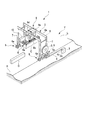
- FIG. 1 is an outline view showing an outline of an outline of a tire type crane (RTG) according to the first embodiment of the present invention.
- a tire type crane system 1 is located on a traveling lane L installed on a road surface R in a container yard Y, and a traveling lane L is obtained by rotating a tire 6a of the traveling mechanism 6 with a traveling motor. Self-propelled above and unloads container C.
- the tire-type crane system 1 includes a crane main body 3 that travels on the road surface R by tires 6a, and a power supply that is a cable that extends from the crane main body 3 and is connected to the ground power supply facility 2 in the travel lane L.
- a cable 4, a cable reel 5 provided on the crane body 3 for winding and unwinding the feeding cable 4, and a box 10 for storing a power supply device, a control device for the crane body 3, and the like are provided.
- the crane body 3 includes the traveling mechanism 6 described above, a pair of leg portions 7 that are erected substantially parallel to each other and that can be traveled by the traveling mechanism 6, a beam portion 8 that is installed between the leg portions 7, and a beam And a suspension mechanism 9 suspended from the portion 8.
- the pair of leg portions 7 support the beam portion 8 and the suspension mechanism 9, and the beam portion 8 supports the suspension mechanism 9 so as to be suspended.
- a guide rail 8 a is provided along the longitudinal direction of the beam portion 8, and the suspension mechanism 9 can travel in the longitudinal direction of the beam portion 8 along the guide rail 8 a.
- the suspension mechanism 9 includes a trolley 9a that can travel along the guide rail 8a of the beam portion 8, a spreader 9b that holds the container C, and a suspension that suspends the spreader 9b from the trolley 9a.
- a rope 9c and a hoisting machine 9d for winding and unwinding the hanging rope 9c are provided.
- the crane body 3 performs the loading and unloading operation of the container C. Specifically, when the spreader 9b grasps the container C, the hoisting machine 9d lifts the container C by hoisting the suspension rope 9c with the power of the hoisting motor. With the container C lifted, the suspension mechanism 9 (trolley 9a) travels in the longitudinal direction of the beam portion 8, and the crane body travels along the travel lane L to move the container C. When the container C moves to the target position, the hoisting machine 9d lowers the container C by returning the winding of the suspension rope 9c.
- the crane main body 3 uses the electric power from the ground power supply facility 2 and the electric power from the power storage device included in the power supply device housed in the box 10 to drive the crane main body 3 and the suspension mechanism.
- Various operations such as running 9 and hoisting of the suspension rope 9c by the hoisting machine 9d are performed.
- a cable-side connector 4 a is provided at the tip of the feeding cable 4 and is connected to the power-side connector 2 a of the ground power supply facility 2.
- the crane body 3 receives power from the ground power supply facility 2 via the power supply cable 4 and supplies power to each part of the crane body 3 through a power supply device housed in the box 10.
- the power supply device controls charging / discharging of the power storage device, and supplies the discharge power of the power storage device to each part of the crane body 3 in addition to the power from the ground power supply facility 2.
- the cable reel 5 winds up the excess of the power supply cable 4 so that the power supply cable 4 is slack and does not hinder the traveling of the crane body 3.
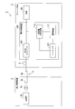
- FIG. 2 is a schematic configuration diagram illustrating a device configuration of the power supply device 100.
- the power supply device 100 includes an AC / DC converter 101, a power storage device 111, a charge / discharge control device 112, and a sequencer 121.
- FIG. 2 also shows the ground power supply facility 2, the power supply cable 4 that connects the ground power supply facility 2 and the power supply device 100, and the load 90 that the power supply device 100 supplies power to.
- the ground power supply facility 2 includes a power supply side connector 2a, a power supply unit 2b, and a transformer 2c.
- the AC power output from the power supply unit 2b is transformed by the transformer 2c and output from the power supply side connector 2a.
- the cable side connector 4a is connected to the power supply side connector 2a, and the power feeding cable 4 supplies the AC power received from the ground power supply facility 2 to the power supply device 100 by the cable side connector 4a.
- the ground power supply facility 2 corresponds to an example of a power supply in the present embodiment.
- the power supply unit 2b may be a power generation facility, or may be a power reception facility that receives a commercial power source or the like, for example.
- the power source in the present embodiment is not limited to an external power source (a power source provided outside the power supply device) such as the ground power source facility 2.
- the power supply apparatus 100 may include a power generator, and the power supply apparatus 100 itself may have a power source.
- the load 90 may be a traveling motor that causes the crane body 3 to travel by rotating the tire 6a (FIG. 1), a hoisting motor that serves as a power source when the hoisting machine 9d winds the suspension rope 9c, or the crane main body 3 It is a general term for the electric power load in the crane main body 3 such as a control device.
- the load 90 can generate regenerative power.
- the traveling mechanism 6 performs regeneration by operating a traveling motor as a regenerative brake when the crane body 3 is braked. Further, when the hoisting machine 9d unwinds the suspension rope 9c and lowers the suspended load, the hoisting machine 9d performs regeneration while operating the hoisting motor as a regenerative brake and adjusting the descending load lowering speed.
- the AC / DC converter 101 converts AC power supplied from the ground power supply facility 2 into DC power having the first target voltage value and supplies the DC power to the load 90.
- the first target voltage value is preset as a fixed voltage value.
- the power storage device 111 includes a secondary battery such as a lead battery or a lithium ion battery, and performs charging and discharging.
- the power storage device 111 is connected to the AC / DC converter 101 in parallel with the load 90 via the charge / discharge control device 112. With this connection relationship, when the voltage value of the power from the AC / DC converter 101 is higher than the voltage value of the power storage device 111, the power storage device 111 is float-charged with the power from the AC / DC converter 101.
- the power storage device 111 includes a BMU (Battery Management Unit), measures the charge rate of the secondary battery, and outputs it to the sequencer 121.
- BMU Battery Management Unit
- the charge / discharge control device 112 controls charging / discharging of the power storage device 111 so that the voltage of the power storage device 111 becomes the second target voltage value.
- the second target voltage value is a variable voltage value set by the sequencer 121.
- Sequencer 121 compares the charging rate of the secondary battery of power storage device 111 (hereinafter simply referred to as “charging rate of power storage device 111”) with a threshold value, and increases or decreases the second target voltage value according to the comparison result.
- the sequencer 121 stores in advance a discharge threshold ShA for switching the power storage device 111 from charging to discharging and a charging threshold ShB for switching the power storage device 111 from discharging to charging.
- the discharge threshold value ShA corresponds to an example of the threshold value in the present embodiment.
- the sequencer 121 corresponds to an example of a target voltage value setting unit in the present embodiment.
- the discharge threshold value ShA is set to be equal to or less than the charging rate obtained by subtracting the regenerative power storage amount from the fully charged state of the power storage device 111.
- the crane main body 3 is braked when the crane main body 3 reaches the container position, and the crane main body 3 when the crane main body 3 reaches the container lowering position. Assume braking and braking of the hoist when the container is lowered. In this case, the total value of the regenerative power expected to be generated by two times of braking of the crane body 3 and one container descent corresponds to the amount of stored regenerative power.
- the maintenance worker of the tire type crane system 1 calculates a charging rate obtained by subtracting the amount of regenerative power stored from the fully charged state, that is, a charging rate that allows for the possibility of charging the regenerative power.
- the maintenance person of the tire type crane system 1 stores the calculated charging rate in the sequencer 121 in advance as the discharge threshold value ShA.
- the maintenance person of the tire-type crane system 1 may store the charge rate obtained by further subtracting the margin considering the battery deterioration from the calculated charge rate as the discharge threshold value ShA in the sequencer 121 in advance. .
- the charging threshold ShB is set to a value smaller than the discharging threshold ShA. If charging threshold ShB ⁇ discharge threshold ShA, power supply device 100 (sequencer 121 and charge / discharge control device 112) can control power storage device 111, but charging is prevented in order to prevent frequent switching of charge / discharge. It is preferable that a dead zone (hysteresis) is provided between the threshold value ShB and the discharge threshold value ShA.
- the power supply device 100 increases the second target voltage value to be larger than the first target voltage value. According to this target voltage value setting, the charge / discharge control device 112 causes the power storage device 111 to discharge. On the other hand, when the charging rate of power storage device 111 becomes equal to or lower than charging threshold ShB, power supply device 100 decreases the second target voltage value to make it smaller than the first target voltage value. According to this target voltage value setting, the charge / discharge control device 112 causes the power storage device 111 to charge.
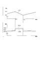
- FIG. 3 is an explanatory diagram showing an example of the target voltage value set by the sequencer 121.
- a line L111 shows an example of the charging rate (State Of Charge; SOC) of the power storage device 111.
- a line L121 indicates an example of the second target voltage value set by the sequencer 121.
- a line L122 indicates an example of an intermediate voltage value between the AC / DC converter 101 and the charge / discharge control device 112.
- the sequencer 121 sets the target voltage value (second target voltage value) of the power storage device 111 to a voltage value Vdset0 that is smaller than the voltage value Vpset that is the output voltage target value (first target voltage value) of the AC / DC converter 101. Is set. Based on this voltage target value setting, charge / discharge control device 112 controls power storage device 111 such that the voltage value of power storage device 111 becomes voltage value Vdset0. As a result, the voltage on the AC / DC converter 101 side becomes higher than the voltage on the power storage device 111 side, and floating charging is performed from the AC / DC converter 101 to the power storage device 111.
- the charging rate of the power storage device 111 is increased by floating charging, and the charging rate reaches the discharge threshold ShA at time T11. Then, the sequencer 121 sets the target voltage value (second target voltage value) of the power storage device 111 to a voltage value Vdset1 that is larger than the voltage value Vpset that is the output voltage target value (first target voltage value) of the AC / DC converter 101. Is set. Based on this voltage target value setting, charge / discharge control device 112 controls power storage device 111 so that the voltage value of power storage device 111 becomes voltage value Vdset1. As a result, the voltage on the power storage device 111 side becomes higher than the voltage on the AC / DC converter 101 side, and the power storage device 111 discharges to the load 90.
- the charging rate of the power storage device 111 decreases due to the discharge, and the charging rate reaches the charging threshold ShB at time T12. Then, the sequencer 121 returns the target voltage value (second target voltage value) of the power storage device 111 to the voltage value Vdset0. Thereby, as before time T11, the voltage on the AC / DC converter 101 side becomes higher than the voltage on the power storage device 111 side, and floating charging is performed from the AC / DC converter 101 to the power storage device 111. In the example of FIG. 3, the power load of the load 90 is in a small state, and the influence of the voltage drop is small. For this reason, the intermediate voltage value indicated by the line L122 is a value between the first target voltage value and the second target voltage value.
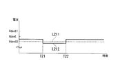
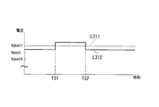
- FIG. 4 is an explanatory diagram showing an example of the intermediate voltage value at the time of high load.
- a line L211 shows an example of the second target voltage value set by the sequencer 121.
- the sequencer 121 continues to set the second target voltage value to a voltage value Vdset0 that is smaller than the first target voltage value.
- a line L212 indicates an example of an intermediate voltage value between the AC / DC converter 101 and the charge / discharge control device 112.
- the load of the load 90 Prior to time T21, the load of the load 90 is in a small state. Thus, floating charging is performed from AC / DC converter 101 to power storage device 111 as in the state before time T11 in FIG. On the other hand, from time T21 to time T22, the power load of the load 90 is in a large state. For this reason, a voltage drop occurs and the intermediate voltage value indicated by the line L212 is smaller than the second target voltage value indicated by the line L211. As a result, the voltage of the power storage device 111 becomes higher than the voltage of the connection destination (particularly the load 90), and the power storage device 111 discharges to the load 90.
- the sequencer 121 sets the second target voltage value to a voltage value smaller than the first target voltage value
- the power storage device 111 discharges to the load 90. Do.
- the maximum value of the power supplied from the ground power supply facility 2 can be reduced, and the power supply voltage can be lowered. Therefore, the voltage value output from the transformer 2c (FIG. 2) can be made relatively small.
- FIG. 5 is an explanatory diagram illustrating an example of the intermediate voltage value during regeneration.
- a line L311 shows an example of the second target voltage value set by the sequencer 121.
- the sequencer 121 continues to set the second target voltage value to the voltage value Vdset1 that is larger than the first target voltage value.
- a line L312 indicates an example of an intermediate voltage value between the AC / DC converter 101 and the charge / discharge control device 112.
- the load 90 Prior to time T31, the load 90 is not regenerating, and the power storage device 111 is discharging to the load 90 as in the state from time T11 to time T12 in FIG.
- the load 90 is regenerating, the intermediate voltage value indicated by the line L312 is increased by the regenerative power, and the intermediate voltage value is larger than the second target voltage value indicated by the line L311. It has become.
- the voltage of the power storage device 111 becomes lower than the voltage of the connection destination (particularly the load 90), and the power storage device 111 charges regenerative power.
- the power storage device 111 charges the regenerative power.
- the power supply device 100 can efficiently charge and discharge the power storage device 111 in accordance with the operation status of the crane body 3 and supply power to the load 90 in that the regenerative power can be stored without being discarded. Can do.
- the charge / discharge control device 112 controls charging / discharging of the power storage device 111 in anticipation of a margin for charging the regenerative power. Therefore, even if the power storage device 111 charges the regenerative power, overcharge is not caused.
- FIG. 6 is a flowchart showing a processing procedure in which the sequencer 121 sets the second target voltage value.
- the sequencer 121 When the sequencer 121 is connected to its own power supply (ON) and is in an operating state, the sequencer 121 performs the processing shown in FIG.
- the sequencer 121 first initializes the second target voltage value to a voltage value Vdset0 that is smaller than the first target voltage value (step S101).
- the power storage device 111 performs charging, but discharges the load 90 when the load 90 becomes high load.
- sequencer 121 determines whether or not the charging rate of power storage device 111 is equal to or greater than discharge threshold ShA (step S102). When it determines with it being less than discharge threshold value ShA (step S102: NO), it returns to step S102. That is, sequencer 121 waits for the charging rate of power storage device 111 to be equal to or greater than discharge threshold value ShA. On the other hand, when it is determined in step S102 that the charging rate of power storage device 111 is equal to or higher than discharge threshold value ShA (step S102: YES), sequencer 121 sets the second target voltage value to a voltage value larger than the first target voltage value. Vdset1 is set (step S103). In the state where the second target voltage value is the voltage value Vdset1, as described above, the power storage device 111 discharges to the load 90, but when the load 90 regenerates, the regenerative power is charged.
- the sequencer 121 determines whether or not the charging rate of the power storage device 111 is equal to or less than the charging threshold ShB (step S104). When it determines with it being larger than the charging threshold ShB (step S104: NO), it returns to step S104. That is, the sequencer 121 waits for the charging rate of the power storage device 111 to be equal to or less than the charging threshold value ShB. On the other hand, when it is determined in step S104 that the charging rate of the power storage device 111 is equal to or less than the charging threshold ShB (step S104: YES), the sequencer 121 sets the second target voltage value to the voltage value Vdset0 (step S105). . Then, it returns to step S102.
- the charge / discharge control device 112 switches charge / discharge of the power storage device 111 by changing the voltage of the power storage device 111 according to the second target voltage value set by the sequencer 121.
- an instantaneous interruption does not arise. That is, there is no delay in the start of power supply from the power storage device 111 or the delay in the start of charging of the power storage device 111 due to the switch switching operation.
- the power supply device 100 can efficiently control charging / discharging of the power storage device 111 according to the operation state of the crane body 3 and supply power to the load 90.
- the sequencer 121 sets the second target voltage value to a voltage value smaller than the first target voltage value, when the power load of the load 90 increases, the power storage device 111 discharges to the load 90. Thereby, the maximum value of the power supplied from the ground power supply facility 2 can be reduced, and the power supply voltage can be lowered. Therefore, the voltage value output from the transformer 2c (FIG. 2) can be made relatively small.
- the power storage device 111 charges the regenerative power.
- the power supply device 100 can efficiently charge and discharge the power storage device 111 in accordance with the operation status of the crane body 3 and supply power to the load 90 in that the regenerative power can be stored without being discarded. Can do.
- charging / discharging control device 112 controls charging / discharging of power storage device 111 in anticipation of a margin for charging regenerative power. Therefore, even if power storage device 111 charges regenerative power, overcharging does not occur.
- the sequencer 121 can control charging / discharging of the power storage device 111 with a simple configuration in that the charge / discharge of the power storage device 111 can be controlled by setting the target voltage value with reference to only the charging rate of the power storage device 111. can do. Further, in power supply device 100, even when AC / DC converter 101 does not have an output voltage set value switching function, charging / discharging of power storage device 111 can be controlled.
- the charge / discharge control device 112 switches the voltage setting value.
- the following effects can be obtained. That is, when a charge / discharge control device and a power storage device are additionally provided for an electric reel type gate crane without an AC / DC converter mounted power storage device, it is necessary to add an output voltage set value switching function to the AC / DC converter. There is no. In this respect, additional work can be reduced.
- the application range of this invention is not restricted to this.
- the present invention can be applied to various devices that use both power from a power source and power from a power storage device such as a series hybrid hybrid car and a hybrid railway vehicle. The same applies to a second embodiment described later.
- the sequencer 121 may change the target voltage value based on the operation status of the crane body 3. For example, when there is no power fluctuation of the load 90 (both for the winding operation and the traveling operation) within the set time, the charge / discharge control device 112 performs charging or discharging of the power storage device 111 according to the instruction of the sequencer 121. At least one of them may be stopped. When the load power fluctuation is detected, the charge / discharge control device 112 may restore the power storage device 111 to the original state. Thereby, it is possible to avoid unnecessary repetition of charging / discharging operation when there is no load power fluctuation (both for the winding operation and the traveling operation). The same applies to the second embodiment described below.
- FIG. 7 is a schematic configuration diagram showing a device configuration of the power supply device according to the second embodiment of the present invention.
- the power supply device 200 includes an AC / DC converter 201, a power storage device 111, a charge / discharge control device 212, and a sequencer 221.
- FIG. 7 shows the ground power supply facility 2, the power supply cable 4 that connects the ground power supply facility 2 and the power supply device 100, and the load 90 to which the power supply device 100 supplies power.
- the tire crane system 1b differs from the tire crane system 1 (FIG. 2) in that the sequencer 221 changes the first target voltage value instead of the second target voltage value.
- the sequencer 221 increases the first target voltage value to be larger than the second target voltage value when the charging rate of the power storage device 111 becomes equal to or higher than the discharge threshold value ShA.
- the AC / DC converter 201 changes the output voltage value of the AC / DC converter 201 itself according to the first target voltage value set by the sequencer 221.
- the charge / discharge control device 212 controls the charge / discharge of the power storage device 111 by controlling the voltage value of the power storage device 111 based on the second target voltage value.
- the charge / discharge control device 212 differs from the charge / discharge control device 112 in that the second target value is a fixed value.
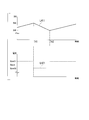
- FIG. 8 is an explanatory diagram illustrating an example of the target voltage value set by the sequencer 221.
- a line L411 indicates an example of a state of charge (SOC) of the power storage device 111.
- a line L421 indicates an example of the first target voltage value set by the sequencer 221.
- the sequencer 221 sets the output voltage target value (first target voltage value) of the AC / DC converter 201 to a voltage value Vpset1 that is larger than the voltage value Vdset that is the target voltage value (second target voltage value) of the power storage device 111. Is set.
- the AC / DC converter 201 controls the AC / DC converter 201 itself so that the output voltage value becomes the voltage value Vpset1. As a result, the voltage on the AC / DC converter 201 side becomes higher than the voltage on the power storage device 111 side, and floating charging is performed from the AC / DC converter 201 to the power storage device 111.
- the charging rate of the power storage device 111 is increased by floating charging, and the charging rate reaches the discharge threshold ShA at time T41. Then, the sequencer 221 sets the output voltage target value (first target voltage value) of the AC / DC converter 201 to a voltage value Vpset0 that is smaller than the voltage value Vdset that is the target voltage value (second target voltage value) of the power storage device 111. Is set. Based on this voltage target value setting, the AC / DC converter 201 controls the AC / DC converter 201 itself so that the output voltage value becomes the voltage value Vpset0. As a result, the voltage on the power storage device 111 side becomes higher than the voltage on the AC / DC converter 201 side, and the power storage device 111 discharges to the load 90.
- the charging rate of the power storage device 111 decreases due to discharging, and the charging rate reaches the charging threshold ShB at time T42. Then, the sequencer 221 returns the output voltage target value (first target voltage value) of the AC / DC converter 201 to the voltage value Vpset1. Thereby, as before time T41, the voltage on the AC / DC converter 201 side becomes higher than the voltage on the power storage device 111 side, and floating charging is performed from the AC / DC converter 201 to the power storage device 111.
- charging / discharging of the power storage device 111 can be switched similarly to the case of the power supply device 100. Even when the load 90 is at a high load, as described with reference to FIG. 4, even when the sequencer 221 sets the first target voltage value to a voltage value larger than the second target voltage value, When the power load of 90 increases, the power storage device 111 discharges to the load 90. Thereby, the maximum value of the power supplied from the ground power supply facility 2 can be reduced, and the power supply voltage can be lowered. Therefore, the voltage value output from the transformer 2c (FIG. 2) can be made relatively small.
- the power storage device 111 charges regenerative power.
- the power supply device 200 can efficiently charge and discharge the power storage device 111 in accordance with the operation status of the crane body 3b and supply power to the load 90 in that the regenerative power can be stored without being discarded. Can do.
- the charge / discharge control device 112 controls the charge / discharge of the power storage device 111 in anticipation of a margin for regenerative power. Therefore, even if the power storage device 111 charges regenerative power, overcharging does not occur.
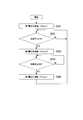
- FIG. 9 is a flowchart showing a processing procedure in which the sequencer 221 sets the first target voltage value.
- the sequencer 221 When the sequencer 221 is connected to its own power supply and enters an operating state, the sequencer 221 performs the processing shown in FIG.
- the sequencer 221 first initializes the first target voltage value to a voltage value Vpset1 that is larger than the second target voltage value (step S201).
- the power storage device 111 performs charging, but discharges the load 90 when the load 90 becomes high load.
- sequencer 221 determines whether or not the charging rate of power storage device 111 is equal to or greater than discharge threshold ShA (step S202). When it determines with it being less than the discharge threshold value ShA (step S202: NO), it returns to step S202. That is, sequencer 221 waits for the charging rate of power storage device 111 to be equal to or greater than discharge threshold value ShA. On the other hand, when it is determined in step S202 that the charging rate of power storage device 111 is equal to or higher than discharge threshold value ShA (step S202: YES), sequencer 221 sets the first target voltage value to a voltage value smaller than the second target voltage value. Vpset0 is set (step S203). In the state where the second target voltage value is the voltage value Vpset0, as described above, the power storage device 111 discharges to the load 90, but when the load 90 regenerates, the regenerative power is charged.
- the sequencer 221 determines whether or not the charging rate of the power storage device 111 is equal to or less than the charging threshold ShB (step S204). When it determines with it being larger than the charging threshold ShB (step S204: NO), it returns to step S204. That is, the sequencer 221 waits for the charging rate of the power storage device 111 to be equal to or lower than the charging threshold ShB. On the other hand, when it is determined in step S204 that the charging rate of the power storage device 111 is equal to or less than the charging threshold ShB (step S204: YES), the sequencer 221 sets the first target voltage value to the voltage value Vpset1 (step S205). . Thereafter, the process returns to step S202.
- the AC / DC converter 201 switches charging / discharging of the power storage device 111 by changing the output voltage value of the AC / DC converter 201 itself according to the first target voltage value set by the sequencer 221.
- an instantaneous interruption does not arise. That is, there is no delay in the start of power supply from the power storage device 111 or the delay in the start of charging of the power storage device 111 due to the switch switching operation.
- the power supply device 200 can efficiently control charging / discharging of the power storage device 111 in accordance with the operation state of the crane body 3b and supply power to the load 90.
- the power storage device 111 discharges to the load 90 when the power load of the load 90 increases. Thereby, the maximum value of the power supplied from the ground power supply facility 2 can be reduced, and the power supply voltage can be lowered. Therefore, the voltage value output from the transformer 2c (FIG. 2) can be made relatively small.
- the power storage device 111 charges regenerative power.
- the power supply device 200 can efficiently charge and discharge the power storage device 111 in accordance with the operation status of the crane body 3b and supply power to the load 90 in that the regenerative power can be stored without being discarded. Can do.
- charging / discharging control device 212 controls charging / discharging of power storage device 111 in anticipation of a margin for charging regenerative power, so that overcharging does not occur even when power storage device 111 charges regenerative power.
- the sequencer 221 can control charging / discharging of the power storage device 111 with a simple configuration in that the charge / discharge of the power storage device 111 can be controlled by setting the target voltage value with reference to only the charging rate of the power storage device 111. can do. Further, in power supply device 200, charging / discharging of power storage device 111 can be controlled even when charging / discharging control device 212 does not have a voltage command value switching function.
- a program for realizing all or part of the functions of the charge / discharge control devices 112 and 212 and the sequencers 121 and 221 is recorded on a computer-readable recording medium, and the program recorded on the recording medium is stored in the computer.
- the processing of each unit may be performed by reading it into the system and executing it.
- the “computer system” includes an OS and hardware such as peripheral devices. Further, the “computer system” includes a homepage providing environment (or display environment) if a WWW system is used.
- the “computer-readable recording medium” refers to a storage device such as a flexible medium, a magneto-optical disk, a portable medium such as a ROM or a CD-ROM, and a hard disk incorporated in a computer system.
- the “computer-readable recording medium” dynamically holds a program for a short time like a communication line when transmitting a program via a network such as the Internet or a communication line such as a telephone line.
- a volatile memory in a computer system serving as a server or a client in that case and a program that holds a program for a certain period of time are also included.
- the program may be a program for realizing a part of the functions described above, and may be a program capable of realizing the functions described above in combination with a program already recorded in a computer system.
- the present invention is a power supply device that supplies power to a power load, wherein the power conversion device that converts AC power supplied from a power source into DC power of a first target voltage value and supplies the power to the power load; and A power storage device connected in parallel with the power load to the power conversion device and capable of charging / discharging, a charge / discharge control device for controlling charge / discharge so that a voltage value of the power storage device becomes a second target voltage value, and the power storage device And a target voltage value setting unit that increases or decreases at least one of the first target voltage value and the second target voltage value according to the comparison result.
- ADVANTAGE OF THE INVENTION According to this invention, with respect to the apparatus which uses power supply electric power and the discharge power of an electrical storage apparatus together, electric power supply can be performed by controlling charging / discharging efficiently according to the operation condition of an apparatus.
Abstract
This power supply apparatus that supplies power to an electric load is provided with: a power conversion apparatus, which converts alternating current power to direct current power at a first target voltage value, said alternating current power having been supplied from a power supply, and which supplies the direct current power to the electric load; a chargeable/dischargeable electric storage apparatus connected to the power conversion apparatus, said electric storage apparatus being connected parallel to the electric load; a charge/discharge control apparatus that controls charging and discharging such that the voltage value of the electric storage apparatus is at a second target voltage value; and a target voltage value setting section, which compares the charge rate of the electric storage apparatus with a threshold value, and which increases/reduces the first target voltage value and/or the second target voltage value corresponding to comparison results.
Description
本発明は、電力供給装置、電力供給方法およびプログラムに関する。
本願は、2012年10月9日に、日本に出願された特願2012-224249号に基づき優先権を主張し、その内容をここに援用する。 The present invention relates to a power supply device, a power supply method, and a program.
This application claims priority based on Japanese Patent Application No. 2012-224249 filed in Japan on October 9, 2012, the contents of which are incorporated herein by reference.
ハイブリッド式門型クレーンやハイブリッドカーやハイブリッド鉄道車両などの機器において、エンジン発電機と蓄電装置を備えるシリーズハイブリッド方式の機器がある。また、門型クレーンにおいて、エンジン発電機に代えてクレーン外部の電源から電力供給を受ける機器がある(例えば、特許文献1)。
これらエンジン発電機または外部電源などからの電源電力と蓄電装置の放電電力とを併用する機器では、電力負荷の大きい状態で、電源電力に加えて蓄電装置の放電電力を用いることで、電源からの供給電力の最大値を低減させることができる。 Among devices such as hybrid portal cranes, hybrid cars, and hybrid railway vehicles, there are series hybrid devices that include an engine generator and a power storage device. Moreover, in a portal crane, there exists an apparatus which receives electric power supply from the power supply outside a crane instead of an engine generator (for example, patent document 1).
In devices that use both power from the engine generator or external power supply and the discharge power of the power storage device, use the discharge power of the power storage device in addition to the power supply power when the power load is large. The maximum value of the power supply can be reduced.
例えば、外部電源から電力供給を受け、かつ、蓄電装置を備えた門型クレーンが、低負荷時には、外部電源からの電力にて走行用モータや巻き上げ用モータなど各種負荷を動作させるとともに、当該外部電源からの電力にて蓄電装置を充電する。
一方、吊荷の巻き上げ時など高負荷時には、蓄電装置が放電を行い、外部電源からの電力に加えて蓄電装置からの放電電力が負荷に供給される。蓄電装置が負荷に電力供給することで、電源からの供給電力の最大値を低減させられるので、電源電圧を下げることができる。 For example, a portal crane that is supplied with power from an external power source and that has a power storage device operates various loads such as a traveling motor and a hoisting motor with power from the external power source when the load is low, The power storage device is charged with power from the power source.
On the other hand, when the load is high, such as when lifting a suspended load, the power storage device discharges, and in addition to the power from the external power source, the discharge power from the power storage device is supplied to the load. Since the power storage device supplies power to the load, the maximum value of power supplied from the power source can be reduced, so that the power supply voltage can be lowered.
クレーンなどの機器が、電源からの電力と蓄電装置からの電力とを用いて動作する場合、機器の動作状況に応じて効率よく充放電を制御することが課題となる。例えば、蓄電装置の充放電を速やかに切り替えて遅滞無く充放電を行うことが望まれる。
When a device such as a crane operates using electric power from a power source and electric power from a power storage device, it is a problem to efficiently control charging and discharging according to the operation state of the device. For example, it is desired to perform charging / discharging without delay by quickly switching between charging / discharging of the power storage device.
本発明は、電源電力と蓄電装置の放電電力とを併用する機器に対して、機器の動作状況に応じて効率よく充放電を制御して電力供給を行える電力供給装置、電力供給方法およびプログラムを提供する。
The present invention relates to a power supply device, a power supply method, and a program capable of efficiently supplying and supplying power by controlling charging / discharging according to an operation state of a device for a device that uses both power source power and discharge power of a power storage device. provide.
本発明の一態様による電力供給装置は、電力負荷に電力を供給する電力供給装置であって、電源から供給される交流電力を第1目標電圧値の直流電力に変換して前記電力負荷に供給する電力変換装置と、前記電力変換装置に前記電力負荷と並列に接続され、充放電可能な蓄電装置と、前記蓄電装置の電圧値が第2目標電圧値となるよう充放電を制御する充放電制御装置と、前記蓄電装置の充電率を閾値と比較し、比較結果に応じて第1目標電圧値または第2目標電圧値の少なくとも一方を増減する目標電圧値設定部と、を具備する。
A power supply device according to an aspect of the present invention is a power supply device that supplies power to a power load, and converts AC power supplied from a power source into DC power having a first target voltage value and supplies the power to the power load. A power conversion device that is connected to the power conversion device in parallel with the power load and that can be charged / discharged, and charge / discharge that controls charging / discharging so that a voltage value of the power storage device becomes a second target voltage value A control device, and a target voltage value setting unit that compares a charging rate of the power storage device with a threshold and increases or decreases at least one of the first target voltage value and the second target voltage value according to the comparison result.
また、本発明の他の態様による電力供給装置は、上述の電力供給装置であって、前記電力負荷は回生電力を生成可能であり、前記閾値は、前記蓄電装置の満充電の状態から前記回生電力の蓄電分を差し引いた充電率以下に設定されており、前記目標電圧値設定部は、前記蓄電装置の充電率が前記閾値以上になると、前記第2目標電圧値が前記第1目標電圧値より大きくなるように前記第1目標電圧値または前記第2目標電圧値の少なくとも一方を増減する。
A power supply device according to another aspect of the present invention is the above-described power supply device, wherein the power load can generate regenerative power, and the threshold value is determined based on a state in which the power storage device is fully charged. The target voltage value setting unit is set to be equal to or lower than a charging rate obtained by subtracting the charged amount of electric power, and the second target voltage value is set to the first target voltage value when the charging rate of the power storage device is equal to or higher than the threshold value. At least one of the first target voltage value and the second target voltage value is increased or decreased so as to be larger.
また、本発明の他の態様による電力供給装置は、上述の電力供給装置であって、前記目標電圧値設定部は、前記蓄電装置の充電率が前記閾値以下になると、前記第2目標電圧値を減少させて前記第1目標電圧値より小さくする。
The power supply device according to another aspect of the present invention is the above-described power supply device, wherein the target voltage value setting unit is configured to output the second target voltage value when a charge rate of the power storage device is equal to or lower than the threshold value. Is made smaller than the first target voltage value.
また、本発明の他の態様による電力供給装置は、上述の電力供給装置であって、前記目標電圧値設定部は、前記蓄電装置の充電率が前記閾値以下になると、前記第1目標電圧値を増加させて前記第2目標電圧値より大きくする。
The power supply device according to another aspect of the present invention is the above-described power supply device, wherein the target voltage value setting unit is configured such that when the charge rate of the power storage device is equal to or lower than the threshold value, the first target voltage value Is made larger than the second target voltage value.
また、本発明の他の態様による電力供給装置は、上述の電力供給装置であって、前記電力負荷はクレーン装置であり、前記目標電圧値設定部は、前記電力負荷の電力変動が所定時間以上無い場合、前記蓄電装置の充電または放電の少なくともいずれか一方を停止させる。
A power supply device according to another aspect of the present invention is the above-described power supply device, wherein the power load is a crane device, and the target voltage value setting unit has a power fluctuation of the power load of a predetermined time or more. If not, at least one of charging and discharging of the power storage device is stopped.
また、本発明の他の態様による電力供給方法は、電源から供給される交流電力を第1目標電圧値の直流電力に変換して電力負荷に供給する電力変換装置と、前記電力変換装置に前記電力負荷と並列に接続され、充放電可能な蓄電装置と、を具備する電力供給装置の電力供給方法であって、前記蓄電装置の電圧値が第2目標電圧値となるよう充放電を制御する充放電制御ステップと、前記蓄電装置の充電率を閾値と比較し、比較結果に応じて第1目標電圧値または第2目標電圧値の少なくとも一方を増減する目標電圧値設定ステップと、を具備する。
According to another aspect of the present invention, there is provided a power supply method that converts AC power supplied from a power source into DC power having a first target voltage value and supplies the power to a power load, and A power supply method for a power supply device comprising: a power storage device connected in parallel with a power load and capable of charging and discharging, wherein charge / discharge is controlled so that a voltage value of the power storage device becomes a second target voltage value A charge / discharge control step; and a target voltage value setting step of comparing the charging rate of the power storage device with a threshold value and increasing or decreasing at least one of the first target voltage value and the second target voltage value according to the comparison result. .
また、本発明の他の態様によるプログラムは、電源から供給される交流電力を第1目標電圧値の直流電力に変換して電力負荷に供給する電力変換装置と、前記電力変換装置に前記電力負荷と並列に接続され、充放電可能な蓄電装置と、を具備する電力供給装置を制御するコンピュータに、前記蓄電装置の電圧値が第2目標電圧値となるよう充放電を制御する充放電制御ステップと、前記蓄電装置の充電率を閾値と比較し、比較結果に応じて第1目標電圧値または第2目標電圧値の少なくとも一方を増減する目標電圧値設定ステップと、を実行させるためのプログラムである。
According to another aspect of the present invention, there is provided a program for converting AC power supplied from a power source into DC power having a first target voltage value and supplying the power load to the power load; Charge / discharge control step of controlling charging / discharging so that the voltage value of the power storage device becomes the second target voltage value in a computer that controls the power supply device including the power storage device connected in parallel with the power storage device And a target voltage value setting step of comparing the charging rate of the power storage device with a threshold value and increasing or decreasing at least one of the first target voltage value or the second target voltage value according to the comparison result. is there.
上記した電力供給装置、電力供給方法およびプログラムによれば、電源電力と蓄電装置の放電電力とを併用する機器に対して、機器の動作状況に応じて効率よく充放電を制御して電力供給を行うことができる。
According to the power supply device, the power supply method, and the program described above, for the device that uses both the power supply and the discharge power of the power storage device, the power supply is efficiently controlled according to the operation status of the device. It can be carried out.
以下、発明の実施の形態を通じて本発明を説明するが、以下の実施形態は特許請求の範囲にかかる発明を限定するものではない。また、実施形態の中で説明されている特徴の組み合わせの全てが発明の解決手段に必須であるとは限らない。
Hereinafter, the present invention will be described through embodiments of the invention, but the following embodiments do not limit the invention according to the claims. In addition, not all the combinations of features described in the embodiments are essential for the solving means of the invention. *
<第1の実施形態>
図1は、本発明の第1の実施形態におけるタイヤ式クレーン(Rubber Tired Gantry Crane;RTG)の外形の概略を示す外形図である。
同図において、タイヤ式クレーンシステム1は、コンテナヤードY内の路面R上に設置された走行レーンL上に位置し、走行機構6が有するタイヤ6aを走行用モータにて回転させて走行レーンL上を自走し、コンテナCの積み下ろしを行う。 <First Embodiment>
FIG. 1 is an outline view showing an outline of an outline of a tire type crane (RTG) according to the first embodiment of the present invention.
In the figure, a tiretype crane system 1 is located on a traveling lane L installed on a road surface R in a container yard Y, and a traveling lane L is obtained by rotating a tire 6a of the traveling mechanism 6 with a traveling motor. Self-propelled above and unloads container C.
図1は、本発明の第1の実施形態におけるタイヤ式クレーン(Rubber Tired Gantry Crane;RTG)の外形の概略を示す外形図である。
同図において、タイヤ式クレーンシステム1は、コンテナヤードY内の路面R上に設置された走行レーンL上に位置し、走行機構6が有するタイヤ6aを走行用モータにて回転させて走行レーンL上を自走し、コンテナCの積み下ろしを行う。 <First Embodiment>
FIG. 1 is an outline view showing an outline of an outline of a tire type crane (RTG) according to the first embodiment of the present invention.
In the figure, a tire
より具体的には、タイヤ式クレーンシステム1は、タイヤ6aにより路面R上を走行するクレーン本体3と、クレーン本体3から延びて、走行レーンLの地上電源設備2に接続されるケーブルである給電ケーブル4と、クレーン本体3に設けられて給電ケーブル4の巻き取り及び巻き出しを行うケーブルリール5と、電力供給装置やクレーン本体3の制御装置等を収納するボックス10とを具備する。
クレーン本体3は、上記の走行機構6と、互いに略平行に立設されて走行機構6により走行可能な一対の脚部7と、脚部7間に上部で架設された梁部8と、梁部8に吊設された吊下機構9とを具備する。 More specifically, the tire-type crane system 1 includes a crane main body 3 that travels on the road surface R by tires 6a, and a power supply that is a cable that extends from the crane main body 3 and is connected to the ground power supply facility 2 in the travel lane L. A cable 4, a cable reel 5 provided on the crane body 3 for winding and unwinding the feeding cable 4, and a box 10 for storing a power supply device, a control device for the crane body 3, and the like are provided.
Thecrane body 3 includes the traveling mechanism 6 described above, a pair of leg portions 7 that are erected substantially parallel to each other and that can be traveled by the traveling mechanism 6, a beam portion 8 that is installed between the leg portions 7, and a beam And a suspension mechanism 9 suspended from the portion 8.
クレーン本体3は、上記の走行機構6と、互いに略平行に立設されて走行機構6により走行可能な一対の脚部7と、脚部7間に上部で架設された梁部8と、梁部8に吊設された吊下機構9とを具備する。 More specifically, the tire-
The
一対の脚部7は、梁部8及び吊下機構9を支持しており、梁部8は、吊下機構9を吊り下げるように支持している。そして、梁部8の長手方向に沿ってガイドレール8aが設けられており、吊下機構9は、ガイドレール8aに沿って梁部8の長手方向に走行可能である。
より具体的には、吊下機構9は、梁部8のガイドレール8aに沿って走行可能なトロリ9aと、コンテナCを把持するスプレッダー9bと、トロリ9aからスプレッダー9bを吊り下げている吊下ロープ9cと、吊下ロープ9cの巻上げ及び巻出しを行う巻上機9dを備えている。 The pair ofleg portions 7 support the beam portion 8 and the suspension mechanism 9, and the beam portion 8 supports the suspension mechanism 9 so as to be suspended. A guide rail 8 a is provided along the longitudinal direction of the beam portion 8, and the suspension mechanism 9 can travel in the longitudinal direction of the beam portion 8 along the guide rail 8 a.
More specifically, thesuspension mechanism 9 includes a trolley 9a that can travel along the guide rail 8a of the beam portion 8, a spreader 9b that holds the container C, and a suspension that suspends the spreader 9b from the trolley 9a. A rope 9c and a hoisting machine 9d for winding and unwinding the hanging rope 9c are provided.
より具体的には、吊下機構9は、梁部8のガイドレール8aに沿って走行可能なトロリ9aと、コンテナCを把持するスプレッダー9bと、トロリ9aからスプレッダー9bを吊り下げている吊下ロープ9cと、吊下ロープ9cの巻上げ及び巻出しを行う巻上機9dを備えている。 The pair of
More specifically, the
かかる構成にて、クレーン本体3は、コンテナCの積み降ろし作動を行う。具体的には、スプレッダー9bがコンテナCを把持すると、巻上機9dが巻き上げ用モータの動力にて吊下ロープ9cを巻き上げることでコンテナCを持ち上げる。コンテナCを持ち上げた状態で、吊下機構9(トロリ9a)が梁部8の長手方向に走行し、また、クレーン本体が走行レーンLに沿って走行して、コンテナCを移動させる。コンテナCが目的位置に移動すると、巻上機9dが吊下ロープ9cの巻きを戻すことでコンテナCを降下させる。
With this configuration, the crane body 3 performs the loading and unloading operation of the container C. Specifically, when the spreader 9b grasps the container C, the hoisting machine 9d lifts the container C by hoisting the suspension rope 9c with the power of the hoisting motor. With the container C lifted, the suspension mechanism 9 (trolley 9a) travels in the longitudinal direction of the beam portion 8, and the crane body travels along the travel lane L to move the container C. When the container C moves to the target position, the hoisting machine 9d lowers the container C by returning the winding of the suspension rope 9c.
ここで、クレーン本体3は、地上電源設備2からの電力と、ボックス10に収納された電力供給装置の具備する蓄電装置からの電力とを併用して、クレーン本体3の走行や、吊下機構9の走行や、巻上機9dによる吊下ロープ9cの巻き上げなど各種動作を行う。
具体的には、給電ケーブル4の先端にケーブル側コネクタ4aが設けられて、地上電源設備2の電源側コネクタ2aと接続されている。クレーン本体3は、給電ケーブル4を介して地上電源設備2から電力を受け、ボックス10に収納された電力供給装置を通してクレーン本体3の各部に電力を供給する。また、後述するように、電力供給装置は蓄電装置の充放電を制御し、地上電源設備2からの電力に加えて蓄電装置の放電電力を、クレーン本体3の各部に供給する。
ケーブルリール5は、給電ケーブル4が弛んでクレーン本体3の走行に支障をきたさないよう、給電ケーブル4の余剰分の巻き取りを行う。 Here, the cranemain body 3 uses the electric power from the ground power supply facility 2 and the electric power from the power storage device included in the power supply device housed in the box 10 to drive the crane main body 3 and the suspension mechanism. Various operations such as running 9 and hoisting of the suspension rope 9c by the hoisting machine 9d are performed.
Specifically, a cable-side connector 4 a is provided at the tip of the feeding cable 4 and is connected to the power-side connector 2 a of the ground power supply facility 2. The crane body 3 receives power from the ground power supply facility 2 via the power supply cable 4 and supplies power to each part of the crane body 3 through a power supply device housed in the box 10. Further, as will be described later, the power supply device controls charging / discharging of the power storage device, and supplies the discharge power of the power storage device to each part of the crane body 3 in addition to the power from the ground power supply facility 2.
Thecable reel 5 winds up the excess of the power supply cable 4 so that the power supply cable 4 is slack and does not hinder the traveling of the crane body 3.
具体的には、給電ケーブル4の先端にケーブル側コネクタ4aが設けられて、地上電源設備2の電源側コネクタ2aと接続されている。クレーン本体3は、給電ケーブル4を介して地上電源設備2から電力を受け、ボックス10に収納された電力供給装置を通してクレーン本体3の各部に電力を供給する。また、後述するように、電力供給装置は蓄電装置の充放電を制御し、地上電源設備2からの電力に加えて蓄電装置の放電電力を、クレーン本体3の各部に供給する。
ケーブルリール5は、給電ケーブル4が弛んでクレーン本体3の走行に支障をきたさないよう、給電ケーブル4の余剰分の巻き取りを行う。 Here, the crane
Specifically, a cable-
The
次に、図2を参照して、電力供給装置の構成について説明する。
図2は、電力供給装置100の装置構成を示す概略構成図である。同図において、電力供給装置100は、AC/DCコンバータ101と、蓄電装置111と、充放電制御装置112と、シーケンサ121とを具備する。また、図2には、地上電源設備2、および、地上電源設備2と電力供給装置100とを接続する給電ケーブル4と、電力供給装置100が電力を供給する負荷90とが示されている。 Next, the configuration of the power supply apparatus will be described with reference to FIG.
FIG. 2 is a schematic configuration diagram illustrating a device configuration of thepower supply device 100. In the figure, the power supply device 100 includes an AC / DC converter 101, a power storage device 111, a charge / discharge control device 112, and a sequencer 121. FIG. 2 also shows the ground power supply facility 2, the power supply cable 4 that connects the ground power supply facility 2 and the power supply device 100, and the load 90 that the power supply device 100 supplies power to.
図2は、電力供給装置100の装置構成を示す概略構成図である。同図において、電力供給装置100は、AC/DCコンバータ101と、蓄電装置111と、充放電制御装置112と、シーケンサ121とを具備する。また、図2には、地上電源設備2、および、地上電源設備2と電力供給装置100とを接続する給電ケーブル4と、電力供給装置100が電力を供給する負荷90とが示されている。 Next, the configuration of the power supply apparatus will be described with reference to FIG.
FIG. 2 is a schematic configuration diagram illustrating a device configuration of the
地上電源設備2は、電源側コネクタ2aと、電源部2bと、変圧器2cとを具備し、電源部2bが出力する交流電力を、変圧器2cにて変圧し、電源側コネクタ2aから出力する。上述したように、電源側コネクタ2aにはケーブル側コネクタ4aが接続されており、給電ケーブル4は、ケーブル側コネクタ4aにて地上電源設備2から受電した交流電力を電力供給装置100へ供給する。
The ground power supply facility 2 includes a power supply side connector 2a, a power supply unit 2b, and a transformer 2c. The AC power output from the power supply unit 2b is transformed by the transformer 2c and output from the power supply side connector 2a. . As described above, the cable side connector 4a is connected to the power supply side connector 2a, and the power feeding cable 4 supplies the AC power received from the ground power supply facility 2 to the power supply device 100 by the cable side connector 4a.
なお、地上電源設備2は本実施形態における電源の一例に該当する。電源部2bは、発電設備であってもよいし、例えば商用電源等を受電する受電設備であってもよい。また、本実施形態における電源は、地上電源設備2などの外部電源(電力供給装置の外部に設けられた電源)に限らない。例えば電力供給装置100が発電機を具備するなど、電力供給装置100自らの内部に電源を有するようにしてもよい。
The ground power supply facility 2 corresponds to an example of a power supply in the present embodiment. The power supply unit 2b may be a power generation facility, or may be a power reception facility that receives a commercial power source or the like, for example. Further, the power source in the present embodiment is not limited to an external power source (a power source provided outside the power supply device) such as the ground power source facility 2. For example, the power supply apparatus 100 may include a power generator, and the power supply apparatus 100 itself may have a power source.
負荷90は、タイヤ6a(図1)を回転させてクレーン本体3を走行させる走行用モータや、巻上機9dが吊下ロープ9cを巻き上げる際の動力源となる巻き上げ用モータや、クレーン本体3の制御装置など、クレーン本体3における電力負荷の総称である。
特に、負荷90は、回生電力を生成可能である。具体的には、走行機構6は、クレーン本体3の制動時に走行用モータを回生ブレーキとして動作させて回生を行う。また、巻上機9dは、吊下ロープ9cを巻き戻して吊荷を降下させる際、巻き上げ用モータを回生ブレーキとして動作させて吊荷の降下速度を調整しつつ回生を行う。 Theload 90 may be a traveling motor that causes the crane body 3 to travel by rotating the tire 6a (FIG. 1), a hoisting motor that serves as a power source when the hoisting machine 9d winds the suspension rope 9c, or the crane main body 3 It is a general term for the electric power load in the crane main body 3 such as a control device.
In particular, theload 90 can generate regenerative power. Specifically, the traveling mechanism 6 performs regeneration by operating a traveling motor as a regenerative brake when the crane body 3 is braked. Further, when the hoisting machine 9d unwinds the suspension rope 9c and lowers the suspended load, the hoisting machine 9d performs regeneration while operating the hoisting motor as a regenerative brake and adjusting the descending load lowering speed.
特に、負荷90は、回生電力を生成可能である。具体的には、走行機構6は、クレーン本体3の制動時に走行用モータを回生ブレーキとして動作させて回生を行う。また、巻上機9dは、吊下ロープ9cを巻き戻して吊荷を降下させる際、巻き上げ用モータを回生ブレーキとして動作させて吊荷の降下速度を調整しつつ回生を行う。 The
In particular, the
AC/DCコンバータ101は、地上電源設備2から供給される交流電力を第1目標電圧値の直流電力に変換して負荷90に供給する。本実施形態では、第1目標電圧値は固定の電圧値として予め設定されている。
蓄電装置111は、例えば鉛電池またはリチウムイオン電池などの二次電池を有し、充放電を行う。ここで、蓄電装置111は、充放電制御装置112を介してAC/DCコンバータ101に負荷90と並列に接続されている。かかる接続関係により、AC/DCコンバータ101からの電力の電圧値が蓄電装置111の電圧値より高いときは、蓄電装置111は、AC/DCコンバータ101からの電力にて浮動充電される。一方、AC/DCコンバータ101から電力の電圧値が蓄電装置111の電圧値より低いときは、蓄電装置111は、放電を行って負荷90へ電力を供給する。
また、蓄電装置111は、BMU(Battery Management Unit、電池管理ユニット)を具備し、二次電池の充電率を測定してシーケンサ121へ出力する。 The AC /DC converter 101 converts AC power supplied from the ground power supply facility 2 into DC power having the first target voltage value and supplies the DC power to the load 90. In the present embodiment, the first target voltage value is preset as a fixed voltage value.
Thepower storage device 111 includes a secondary battery such as a lead battery or a lithium ion battery, and performs charging and discharging. Here, the power storage device 111 is connected to the AC / DC converter 101 in parallel with the load 90 via the charge / discharge control device 112. With this connection relationship, when the voltage value of the power from the AC / DC converter 101 is higher than the voltage value of the power storage device 111, the power storage device 111 is float-charged with the power from the AC / DC converter 101. On the other hand, when the voltage value of power from AC / DC converter 101 is lower than the voltage value of power storage device 111, power storage device 111 discharges and supplies power to load 90.
Thepower storage device 111 includes a BMU (Battery Management Unit), measures the charge rate of the secondary battery, and outputs it to the sequencer 121.
蓄電装置111は、例えば鉛電池またはリチウムイオン電池などの二次電池を有し、充放電を行う。ここで、蓄電装置111は、充放電制御装置112を介してAC/DCコンバータ101に負荷90と並列に接続されている。かかる接続関係により、AC/DCコンバータ101からの電力の電圧値が蓄電装置111の電圧値より高いときは、蓄電装置111は、AC/DCコンバータ101からの電力にて浮動充電される。一方、AC/DCコンバータ101から電力の電圧値が蓄電装置111の電圧値より低いときは、蓄電装置111は、放電を行って負荷90へ電力を供給する。
また、蓄電装置111は、BMU(Battery Management Unit、電池管理ユニット)を具備し、二次電池の充電率を測定してシーケンサ121へ出力する。 The AC /
The
The
充放電制御装置112は、蓄電装置111の電圧が第2目標電圧値となるよう、蓄電装置111の充放電を制御する。本実施形態では、第2目標電圧値はシーケンサ121によって設定される可変の電圧値である。
シーケンサ121は、蓄電装置111の二次電池の充電率(以下、単に「蓄電装置111の充電率」と称する)を閾値と比較し、比較結果に応じて第2目標電圧値を増減させる。ここで、シーケンサ121は、蓄電装置111を充電から放電に切り替える放電閾値ShAと、蓄電装置111を放電から充電に切り替える充電閾値ShBとを予め記憶している。このうち放電閾値ShAが、本実施形態における閾値の一例に該当する。また、シーケンサ121は、本実施形態における目標電圧値設定部の一例に該当する。 The charge /discharge control device 112 controls charging / discharging of the power storage device 111 so that the voltage of the power storage device 111 becomes the second target voltage value. In the present embodiment, the second target voltage value is a variable voltage value set by the sequencer 121.
Sequencer 121 compares the charging rate of the secondary battery of power storage device 111 (hereinafter simply referred to as “charging rate of power storage device 111”) with a threshold value, and increases or decreases the second target voltage value according to the comparison result. Here, the sequencer 121 stores in advance a discharge threshold ShA for switching the power storage device 111 from charging to discharging and a charging threshold ShB for switching the power storage device 111 from discharging to charging. Among these, the discharge threshold value ShA corresponds to an example of the threshold value in the present embodiment. The sequencer 121 corresponds to an example of a target voltage value setting unit in the present embodiment.
シーケンサ121は、蓄電装置111の二次電池の充電率(以下、単に「蓄電装置111の充電率」と称する)を閾値と比較し、比較結果に応じて第2目標電圧値を増減させる。ここで、シーケンサ121は、蓄電装置111を充電から放電に切り替える放電閾値ShAと、蓄電装置111を放電から充電に切り替える充電閾値ShBとを予め記憶している。このうち放電閾値ShAが、本実施形態における閾値の一例に該当する。また、シーケンサ121は、本実施形態における目標電圧値設定部の一例に該当する。 The charge /
放電閾値ShAは、蓄電装置111の満充電の状態から回生電力の蓄電分を差し引いた充電率以下に設定されている。例えば、蓄電装置111に蓄電させる回生電力の発生場面として、クレーン本体3がコンテナの位置に到達した際のクレーン本体3の制動と、クレーン本体3がコンテナ降下位置に到達した際のクレーン本体3の制動と、コンテナを降下させる際の巻上機の制動とを想定する。この場合、2回のクレーン本体3の制動と、1回のコンテナ降下とで生じると予想される回生電力の合計値が、回生電力の蓄電分に相当する。
タイヤ式クレーンシステム1のメンテナンス者は、満充電状態から回生電力の蓄電分を差し引いた充電率、すなわち、回生電力を充電できる余裕を見込んだ充電率を算出する。そして、タイヤ式クレーンシステム1のメンテナンス者は、算出した充電率を放電閾値ShAとして、予めシーケンサ121に記憶させておく。あるいは、タイヤ式クレーンシステム1のメンテナンス者が、算出した充電率から電池劣化等を考慮した余裕分をさらに差し引いた充電率を、放電閾値ShAとして予めシーケンサ121に記憶させておくようにしてもよい。 The discharge threshold value ShA is set to be equal to or less than the charging rate obtained by subtracting the regenerative power storage amount from the fully charged state of thepower storage device 111. For example, as a generation scene of regenerative power to be stored in the power storage device 111, the crane main body 3 is braked when the crane main body 3 reaches the container position, and the crane main body 3 when the crane main body 3 reaches the container lowering position. Assume braking and braking of the hoist when the container is lowered. In this case, the total value of the regenerative power expected to be generated by two times of braking of the crane body 3 and one container descent corresponds to the amount of stored regenerative power.
The maintenance worker of the tiretype crane system 1 calculates a charging rate obtained by subtracting the amount of regenerative power stored from the fully charged state, that is, a charging rate that allows for the possibility of charging the regenerative power. The maintenance person of the tire type crane system 1 stores the calculated charging rate in the sequencer 121 in advance as the discharge threshold value ShA. Alternatively, the maintenance person of the tire-type crane system 1 may store the charge rate obtained by further subtracting the margin considering the battery deterioration from the calculated charge rate as the discharge threshold value ShA in the sequencer 121 in advance. .
タイヤ式クレーンシステム1のメンテナンス者は、満充電状態から回生電力の蓄電分を差し引いた充電率、すなわち、回生電力を充電できる余裕を見込んだ充電率を算出する。そして、タイヤ式クレーンシステム1のメンテナンス者は、算出した充電率を放電閾値ShAとして、予めシーケンサ121に記憶させておく。あるいは、タイヤ式クレーンシステム1のメンテナンス者が、算出した充電率から電池劣化等を考慮した余裕分をさらに差し引いた充電率を、放電閾値ShAとして予めシーケンサ121に記憶させておくようにしてもよい。 The discharge threshold value ShA is set to be equal to or less than the charging rate obtained by subtracting the regenerative power storage amount from the fully charged state of the
The maintenance worker of the tire
一方、充電閾値ShBは、放電閾値ShAよりも小さい値に設定されている。なお、充電閾値ShB≦放電閾値ShAであれば、電力供給装置100(シーケンサ121および充放電制御装置112)は蓄電装置111を制御可能であるが、充放電の切替の頻発を防止するため、充電閾値ShBと放電閾値ShAとの間に不感帯(ヒステリシス)が設けられていることが好ましい。
On the other hand, the charging threshold ShB is set to a value smaller than the discharging threshold ShA. If charging threshold ShB ≦ discharge threshold ShA, power supply device 100 (sequencer 121 and charge / discharge control device 112) can control power storage device 111, but charging is prevented in order to prevent frequent switching of charge / discharge. It is preferable that a dead zone (hysteresis) is provided between the threshold value ShB and the discharge threshold value ShA.
電力供給装置100は、蓄電装置111の充電率が放電閾値ShA以上になると、第2目標電圧値を増加させて第1目標電圧値より大きくする。この目標電圧値設定に従って、充放電制御装置112は、蓄電装置111に放電を行わせる。一方、蓄電装置111の充電率が充電閾値ShB以下になると、電力供給装置100は、第2目標電圧値を減少させて第1目標電圧値より小さくする。この目標電圧値設定に従って、充放電制御装置112は、蓄電装置111に充電を行わせる。
When the charging rate of the power storage device 111 is equal to or higher than the discharge threshold ShA, the power supply device 100 increases the second target voltage value to be larger than the first target voltage value. According to this target voltage value setting, the charge / discharge control device 112 causes the power storage device 111 to discharge. On the other hand, when the charging rate of power storage device 111 becomes equal to or lower than charging threshold ShB, power supply device 100 decreases the second target voltage value to make it smaller than the first target voltage value. According to this target voltage value setting, the charge / discharge control device 112 causes the power storage device 111 to charge.
図3は、シーケンサ121が設定する目標電圧値の例を示す説明図である。同図において、線L111は、蓄電装置111の充電率(State Of Charge;SOC)の例を示す。また、線L121は、シーケンサ121が設定する第2目標電圧値の例を示す。また、線L122は、AC/DCコンバータ101と充放電制御装置112との間における中間電圧値の例を示す。
FIG. 3 is an explanatory diagram showing an example of the target voltage value set by the sequencer 121. In the figure, a line L111 shows an example of the charging rate (State Of Charge; SOC) of the power storage device 111. A line L121 indicates an example of the second target voltage value set by the sequencer 121. A line L122 indicates an example of an intermediate voltage value between the AC / DC converter 101 and the charge / discharge control device 112.
時刻T11以前の状態では、蓄電装置111の充電率は放電閾値ShAよりも小さい。そこで、シーケンサ121は、蓄電装置111の目標電圧値(第2目標電圧値)を、AC/DCコンバータ101の出力電圧目標値(第1目標電圧値)である電圧値Vpsetよりも小さい電圧値Vdset0に設定している。この電圧目標値設定に基づいて、充放電制御装置112は、蓄電装置111の電圧値が電圧値Vdset0となるように、蓄電装置111を制御する。これにより、AC/DCコンバータ101側の電圧が蓄電装置111側の電圧より高くなり、AC/DCコンバータ101から蓄電装置111へ浮動充電が行われる。
In a state before time T11, the charging rate of the power storage device 111 is smaller than the discharge threshold ShA. Therefore, the sequencer 121 sets the target voltage value (second target voltage value) of the power storage device 111 to a voltage value Vdset0 that is smaller than the voltage value Vpset that is the output voltage target value (first target voltage value) of the AC / DC converter 101. Is set. Based on this voltage target value setting, charge / discharge control device 112 controls power storage device 111 such that the voltage value of power storage device 111 becomes voltage value Vdset0. As a result, the voltage on the AC / DC converter 101 side becomes higher than the voltage on the power storage device 111 side, and floating charging is performed from the AC / DC converter 101 to the power storage device 111.
浮動充電にて蓄電装置111の充電率が上昇し、時刻T11において充電率が放電閾値ShAに達している。すると、シーケンサ121は、蓄電装置111の目標電圧値(第2目標電圧値)を、AC/DCコンバータ101の出力電圧目標値(第1目標電圧値)である電圧値Vpsetよりも大きい電圧値Vdset1に設定している。この電圧目標値設定に基づいて、充放電制御装置112は、蓄電装置111の電圧値が電圧値Vdset1となるように、蓄電装置111を制御する。これにより、蓄電装置111側の電圧がAC/DCコンバータ101側の電圧より高くなり、蓄電装置111は負荷90へ放電を行う。
The charging rate of the power storage device 111 is increased by floating charging, and the charging rate reaches the discharge threshold ShA at time T11. Then, the sequencer 121 sets the target voltage value (second target voltage value) of the power storage device 111 to a voltage value Vdset1 that is larger than the voltage value Vpset that is the output voltage target value (first target voltage value) of the AC / DC converter 101. Is set. Based on this voltage target value setting, charge / discharge control device 112 controls power storage device 111 so that the voltage value of power storage device 111 becomes voltage value Vdset1. As a result, the voltage on the power storage device 111 side becomes higher than the voltage on the AC / DC converter 101 side, and the power storage device 111 discharges to the load 90.
放電にて蓄電装置111の充電率が低下し、時刻T12において充電率が充電閾値ShBに達している。すると、シーケンサ121は、蓄電装置111の目標電圧値(第2目標電圧値)を、電圧値Vdset0に戻している。これにより、時刻T11以前と同様、AC/DCコンバータ101側の電圧が蓄電装置111側の電圧より高くなり、AC/DCコンバータ101から蓄電装置111へ浮動充電が行われる。
なお、図3の例では、負荷90の電力負荷が小さい状態にあり電圧降下の影響が小さい。このため、線L122の示す中間電圧値は、第1目標電圧値と第2目標電圧値との間の値となっている。 The charging rate of thepower storage device 111 decreases due to the discharge, and the charging rate reaches the charging threshold ShB at time T12. Then, the sequencer 121 returns the target voltage value (second target voltage value) of the power storage device 111 to the voltage value Vdset0. Thereby, as before time T11, the voltage on the AC / DC converter 101 side becomes higher than the voltage on the power storage device 111 side, and floating charging is performed from the AC / DC converter 101 to the power storage device 111.
In the example of FIG. 3, the power load of theload 90 is in a small state, and the influence of the voltage drop is small. For this reason, the intermediate voltage value indicated by the line L122 is a value between the first target voltage value and the second target voltage value.
なお、図3の例では、負荷90の電力負荷が小さい状態にあり電圧降下の影響が小さい。このため、線L122の示す中間電圧値は、第1目標電圧値と第2目標電圧値との間の値となっている。 The charging rate of the
In the example of FIG. 3, the power load of the
次に、図4を参照して、高負荷時における放電について説明する。
図4は、高負荷時における中間電圧値の例を示す説明図である。同図において、線L211は、シーケンサ121が設定する第2目標電圧値の例を示す。図4の例では、シーケンサ121は、第2目標電圧値を、第1目標電圧値よりも小さい電圧値Vdset0に設定し続けている。
また、線L212は、AC/DCコンバータ101と充放電制御装置112との間における中間電圧値の例を示す。 Next, with reference to FIG. 4, the discharge at high load will be described.
FIG. 4 is an explanatory diagram showing an example of the intermediate voltage value at the time of high load. In the figure, a line L211 shows an example of the second target voltage value set by thesequencer 121. In the example of FIG. 4, the sequencer 121 continues to set the second target voltage value to a voltage value Vdset0 that is smaller than the first target voltage value.
A line L212 indicates an example of an intermediate voltage value between the AC /DC converter 101 and the charge / discharge control device 112.
図4は、高負荷時における中間電圧値の例を示す説明図である。同図において、線L211は、シーケンサ121が設定する第2目標電圧値の例を示す。図4の例では、シーケンサ121は、第2目標電圧値を、第1目標電圧値よりも小さい電圧値Vdset0に設定し続けている。
また、線L212は、AC/DCコンバータ101と充放電制御装置112との間における中間電圧値の例を示す。 Next, with reference to FIG. 4, the discharge at high load will be described.
FIG. 4 is an explanatory diagram showing an example of the intermediate voltage value at the time of high load. In the figure, a line L211 shows an example of the second target voltage value set by the
A line L212 indicates an example of an intermediate voltage value between the AC /
時刻T21以前においては、負荷90の電力負荷が小さい状態にある。これにより、図3の時刻T11以前の状態と同様、AC/DCコンバータ101から蓄電装置111へ浮動充電が行われる。
一方、時刻T21から時刻T22においては、負荷90の電力負荷が大きい状態にある。このため、電圧降下が生じて線L212の示す中間電圧値が線L211の示す第2目標電圧値よりも小さくなっている。これにより、蓄電装置111の電圧が接続先(特に負荷90)の電圧よりも高い状態となり、蓄電装置111は負荷90へ放電を行う。 Prior to time T21, the load of theload 90 is in a small state. Thus, floating charging is performed from AC / DC converter 101 to power storage device 111 as in the state before time T11 in FIG.
On the other hand, from time T21 to time T22, the power load of theload 90 is in a large state. For this reason, a voltage drop occurs and the intermediate voltage value indicated by the line L212 is smaller than the second target voltage value indicated by the line L211. As a result, the voltage of the power storage device 111 becomes higher than the voltage of the connection destination (particularly the load 90), and the power storage device 111 discharges to the load 90.
一方、時刻T21から時刻T22においては、負荷90の電力負荷が大きい状態にある。このため、電圧降下が生じて線L212の示す中間電圧値が線L211の示す第2目標電圧値よりも小さくなっている。これにより、蓄電装置111の電圧が接続先(特に負荷90)の電圧よりも高い状態となり、蓄電装置111は負荷90へ放電を行う。 Prior to time T21, the load of the
On the other hand, from time T21 to time T22, the power load of the
このように、シーケンサ121が、第2目標電圧値を第1目標電圧値よりも小さい電圧値に設定している状態でも、負荷90の電力負荷が大きくなると、蓄電装置111は負荷90へ放電を行う。これにより、地上電源設備2からの供給電力の最大値を低減させることができ、電源電圧を下げることができる。従って、変圧器2c(図2)が出力する電圧値を比較的小さくすることができる。
As described above, even when the sequencer 121 sets the second target voltage value to a voltage value smaller than the first target voltage value, when the power load of the load 90 increases, the power storage device 111 discharges to the load 90. Do. Thereby, the maximum value of the power supplied from the ground power supply facility 2 can be reduced, and the power supply voltage can be lowered. Therefore, the voltage value output from the transformer 2c (FIG. 2) can be made relatively small.
また、第2目標電圧値が第1目標電圧値よりも大きい状態でも、蓄電装置111は回生電力を蓄電し得る。
図5は、回生時における中間電圧値の例を示す説明図である。同図において、線L311は、シーケンサ121が設定する第2目標電圧値の例を示す。図5の例では、シーケンサ121は、第2目標電圧値を、第1目標電圧値よりも大きい電圧値Vdset1に設定し続けている。
また、線L312は、AC/DCコンバータ101と充放電制御装置112との間における中間電圧値の例を示す。 In addition, thepower storage device 111 can store regenerative power even when the second target voltage value is larger than the first target voltage value.
FIG. 5 is an explanatory diagram illustrating an example of the intermediate voltage value during regeneration. In the figure, a line L311 shows an example of the second target voltage value set by thesequencer 121. In the example of FIG. 5, the sequencer 121 continues to set the second target voltage value to the voltage value Vdset1 that is larger than the first target voltage value.
A line L312 indicates an example of an intermediate voltage value between the AC /DC converter 101 and the charge / discharge control device 112.
図5は、回生時における中間電圧値の例を示す説明図である。同図において、線L311は、シーケンサ121が設定する第2目標電圧値の例を示す。図5の例では、シーケンサ121は、第2目標電圧値を、第1目標電圧値よりも大きい電圧値Vdset1に設定し続けている。
また、線L312は、AC/DCコンバータ101と充放電制御装置112との間における中間電圧値の例を示す。 In addition, the
FIG. 5 is an explanatory diagram illustrating an example of the intermediate voltage value during regeneration. In the figure, a line L311 shows an example of the second target voltage value set by the
A line L312 indicates an example of an intermediate voltage value between the AC /
時刻T31以前においては、負荷90は回生を行っておらず、図3の時刻T11からT12までの状態と同様、蓄電装置111が負荷90へ放電を行っている。
一方、時刻T31から時刻T32においては、負荷90が回生を行っており、回生電力にて線L312の示す中間電圧値が上昇し、中間電圧値が線L311の示す第2目標電圧値よりも大きくなっている。これにより、蓄電装置111の電圧が接続先(特に負荷90)の電圧よりも低い状態となり、蓄電装置111は回生電力を充電する。 Prior to time T31, theload 90 is not regenerating, and the power storage device 111 is discharging to the load 90 as in the state from time T11 to time T12 in FIG.
On the other hand, from time T31 to time T32, theload 90 is regenerating, the intermediate voltage value indicated by the line L312 is increased by the regenerative power, and the intermediate voltage value is larger than the second target voltage value indicated by the line L311. It has become. As a result, the voltage of the power storage device 111 becomes lower than the voltage of the connection destination (particularly the load 90), and the power storage device 111 charges regenerative power.
一方、時刻T31から時刻T32においては、負荷90が回生を行っており、回生電力にて線L312の示す中間電圧値が上昇し、中間電圧値が線L311の示す第2目標電圧値よりも大きくなっている。これにより、蓄電装置111の電圧が接続先(特に負荷90)の電圧よりも低い状態となり、蓄電装置111は回生電力を充電する。 Prior to time T31, the
On the other hand, from time T31 to time T32, the
このように、シーケンサ121が、第2目標電圧値を第1目標電圧値よりも大きい電圧値に設定している状態でも、負荷90が回生を行うと、蓄電装置111は回生電力を充電する。このように回生電力を捨てずに蓄電できる点で、電力供給装置100は、クレーン本体3の動作状況に応じて効率よく蓄電装置111の充放電を制御して、負荷90へ電力供給を行うことができる。
また、上述したように、充放電制御装置112は、回生電力を充電できる余裕を見込んで蓄電装置111の充放電を制御するので、蓄電装置111が回生電力を充電しても過充電とならない。 As described above, even when thesequencer 121 sets the second target voltage value to a voltage value larger than the first target voltage value, when the load 90 performs regeneration, the power storage device 111 charges the regenerative power. In this way, the power supply device 100 can efficiently charge and discharge the power storage device 111 in accordance with the operation status of the crane body 3 and supply power to the load 90 in that the regenerative power can be stored without being discarded. Can do.
Further, as described above, the charge /discharge control device 112 controls charging / discharging of the power storage device 111 in anticipation of a margin for charging the regenerative power. Therefore, even if the power storage device 111 charges the regenerative power, overcharge is not caused.
また、上述したように、充放電制御装置112は、回生電力を充電できる余裕を見込んで蓄電装置111の充放電を制御するので、蓄電装置111が回生電力を充電しても過充電とならない。 As described above, even when the
Further, as described above, the charge /
次に図6を参照して、電力供給装置100の動作について説明する。
図6は、シーケンサ121が第2目標電圧値を設定する処理手順を示すフローチャートである。シーケンサ121は、自らの電源を接続(ON)されて動作状態となると、同図の処理を行う。
図6の処理において、シーケンサ121は、まず、第2目標電圧値を第1目標電圧値よりも小さい電圧値Vdset0に初期設定する(ステップS101)。第2目標電圧値が電圧値Vdset0となっている状態では、上述したように、蓄電装置111は充電を行うが、負荷90が高負荷になると当該負荷90へ放電を行う。 Next, the operation of thepower supply apparatus 100 will be described with reference to FIG.
FIG. 6 is a flowchart showing a processing procedure in which thesequencer 121 sets the second target voltage value. When the sequencer 121 is connected to its own power supply (ON) and is in an operating state, the sequencer 121 performs the processing shown in FIG.
In the process of FIG. 6, thesequencer 121 first initializes the second target voltage value to a voltage value Vdset0 that is smaller than the first target voltage value (step S101). In the state where the second target voltage value is the voltage value Vdset0, as described above, the power storage device 111 performs charging, but discharges the load 90 when the load 90 becomes high load.
図6は、シーケンサ121が第2目標電圧値を設定する処理手順を示すフローチャートである。シーケンサ121は、自らの電源を接続(ON)されて動作状態となると、同図の処理を行う。
図6の処理において、シーケンサ121は、まず、第2目標電圧値を第1目標電圧値よりも小さい電圧値Vdset0に初期設定する(ステップS101)。第2目標電圧値が電圧値Vdset0となっている状態では、上述したように、蓄電装置111は充電を行うが、負荷90が高負荷になると当該負荷90へ放電を行う。 Next, the operation of the
FIG. 6 is a flowchart showing a processing procedure in which the
In the process of FIG. 6, the
次に、シーケンサ121は、蓄電装置111の充電率が放電閾値ShA以上か否かを判定する(ステップS102)。放電閾値ShA未満であると判定した場合(ステップS102:NO)、ステップS102へ戻る。すなわち、シーケンサ121は、蓄電装置111の充電率が放電閾値ShA以上となるのを待ち受ける。
一方、ステップS102において、蓄電装置111の充電率が放電閾値ShA以上であると判定した場合(ステップS102:YES)、シーケンサ121は、第2目標電圧値を第1目標電圧値よりも大きい電圧値Vdset1に設定する(ステップS103)。第2目標電圧値が電圧値Vdset1となっている状態では、上述したように、蓄電装置111は負荷90への放電を行うが、負荷90が回生すると回生電力を充電する。 Next,sequencer 121 determines whether or not the charging rate of power storage device 111 is equal to or greater than discharge threshold ShA (step S102). When it determines with it being less than discharge threshold value ShA (step S102: NO), it returns to step S102. That is, sequencer 121 waits for the charging rate of power storage device 111 to be equal to or greater than discharge threshold value ShA.
On the other hand, when it is determined in step S102 that the charging rate ofpower storage device 111 is equal to or higher than discharge threshold value ShA (step S102: YES), sequencer 121 sets the second target voltage value to a voltage value larger than the first target voltage value. Vdset1 is set (step S103). In the state where the second target voltage value is the voltage value Vdset1, as described above, the power storage device 111 discharges to the load 90, but when the load 90 regenerates, the regenerative power is charged.
一方、ステップS102において、蓄電装置111の充電率が放電閾値ShA以上であると判定した場合(ステップS102:YES)、シーケンサ121は、第2目標電圧値を第1目標電圧値よりも大きい電圧値Vdset1に設定する(ステップS103)。第2目標電圧値が電圧値Vdset1となっている状態では、上述したように、蓄電装置111は負荷90への放電を行うが、負荷90が回生すると回生電力を充電する。 Next,
On the other hand, when it is determined in step S102 that the charging rate of
次に、シーケンサ121は、蓄電装置111の充電率が充電閾値ShB以下か否かを判定する(ステップS104)。充電閾値ShBより大きいと判定した場合(ステップS104:NO)、ステップS104へ戻る。すなわち、シーケンサ121は、蓄電装置111の充電率が充電閾値ShB以下となるのを待ち受ける。
一方、ステップS104において、蓄電装置111の充電率が充電閾値ShB以下であると判定した場合(ステップS104:YES)、シーケンサ121は、第2目標電圧値を電圧値Vdset0に設定する(ステップS105)。
その後、ステップS102へ戻る。 Next, thesequencer 121 determines whether or not the charging rate of the power storage device 111 is equal to or less than the charging threshold ShB (step S104). When it determines with it being larger than the charging threshold ShB (step S104: NO), it returns to step S104. That is, the sequencer 121 waits for the charging rate of the power storage device 111 to be equal to or less than the charging threshold value ShB.
On the other hand, when it is determined in step S104 that the charging rate of thepower storage device 111 is equal to or less than the charging threshold ShB (step S104: YES), the sequencer 121 sets the second target voltage value to the voltage value Vdset0 (step S105). .
Then, it returns to step S102.
一方、ステップS104において、蓄電装置111の充電率が充電閾値ShB以下であると判定した場合(ステップS104:YES)、シーケンサ121は、第2目標電圧値を電圧値Vdset0に設定する(ステップS105)。
その後、ステップS102へ戻る。 Next, the
On the other hand, when it is determined in step S104 that the charging rate of the
Then, it returns to step S102.
以上のように、充放電制御装置112は、シーケンサ121が設定する第2目標電圧値に応じて蓄電装置111の電圧を変化させることで、蓄電装置111の充放電を切り替える。これにより、スイッチを用いて蓄電装置111の充放電を切り替える必要が無いので瞬断が生じない。すなわち、スイッチ切替動作による蓄電装置111からの電力供給開始の遅れや、蓄電装置111の充電開始の遅れが生じない。この点において、電力供給装置100は、クレーン本体3の動作状況に応じて効率よく蓄電装置111の充放電を制御して、負荷90へ電力供給を行うことができる。
As described above, the charge / discharge control device 112 switches charge / discharge of the power storage device 111 by changing the voltage of the power storage device 111 according to the second target voltage value set by the sequencer 121. Thereby, since it is not necessary to switch charging / discharging of the electrical storage apparatus 111 using a switch, an instantaneous interruption does not arise. That is, there is no delay in the start of power supply from the power storage device 111 or the delay in the start of charging of the power storage device 111 due to the switch switching operation. In this respect, the power supply device 100 can efficiently control charging / discharging of the power storage device 111 according to the operation state of the crane body 3 and supply power to the load 90.
また、シーケンサ121が、第2目標電圧値を第1目標電圧値よりも小さい電圧値に設定している状態でも、負荷90の電力負荷が大きくなると、蓄電装置111は負荷90へ放電を行う。これにより、地上電源設備2からの供給電力の最大値を低減させることができ、電源電圧を下げることができる。従って、変圧器2c(図2)が出力する電圧値を比較的小さくすることができる。
Further, even when the sequencer 121 sets the second target voltage value to a voltage value smaller than the first target voltage value, when the power load of the load 90 increases, the power storage device 111 discharges to the load 90. Thereby, the maximum value of the power supplied from the ground power supply facility 2 can be reduced, and the power supply voltage can be lowered. Therefore, the voltage value output from the transformer 2c (FIG. 2) can be made relatively small.
また、シーケンサ121が、第2目標電圧値を第1目標電圧値よりも大きい電圧値に設定している状態でも、負荷90が回生を行うと、蓄電装置111は回生電力を充電する。このように回生電力を捨てずに蓄電できる点で、電力供給装置100は、クレーン本体3の動作状況に応じて効率よく蓄電装置111の充放電を制御して、負荷90へ電力供給を行うことができる。
また、充放電制御装置112は、回生電力を充電できる余裕を見込んで蓄電装置111の充放電を制御するので、蓄電装置111が回生電力を充電しても過充電とならない。 Even when thesequencer 121 sets the second target voltage value to a voltage value larger than the first target voltage value, when the load 90 performs regeneration, the power storage device 111 charges the regenerative power. In this way, the power supply device 100 can efficiently charge and discharge the power storage device 111 in accordance with the operation status of the crane body 3 and supply power to the load 90 in that the regenerative power can be stored without being discarded. Can do.
In addition, charging / dischargingcontrol device 112 controls charging / discharging of power storage device 111 in anticipation of a margin for charging regenerative power. Therefore, even if power storage device 111 charges regenerative power, overcharging does not occur.
また、充放電制御装置112は、回生電力を充電できる余裕を見込んで蓄電装置111の充放電を制御するので、蓄電装置111が回生電力を充電しても過充電とならない。 Even when the
In addition, charging / discharging
また、シーケンサ121が、蓄電装置111の充電率のみを参照して目標電圧値を設定することで蓄電装置111の充放電を制御できる点で、簡単な構成にて蓄電装置111の充放電を制御することができる。
また、電力供給装置100では、AC/DCコンバータ101に出力電圧設定値切り替え機能が無い場合でも、蓄電装置111の充放電を制御することができる。 In addition, thesequencer 121 can control charging / discharging of the power storage device 111 with a simple configuration in that the charge / discharge of the power storage device 111 can be controlled by setting the target voltage value with reference to only the charging rate of the power storage device 111. can do.
Further, inpower supply device 100, even when AC / DC converter 101 does not have an output voltage set value switching function, charging / discharging of power storage device 111 can be controlled.
また、電力供給装置100では、AC/DCコンバータ101に出力電圧設定値切り替え機能が無い場合でも、蓄電装置111の充放電を制御することができる。 In addition, the
Further, in
また、電力供給装置100では、充放電制御装置112が電圧設定値の切替を行う。これにより、AC/DCコンバータ101が電圧設定値の切替を行う場合との比較において、以下の効果を得られる。
すなわち、AC/DCコンバータ搭載の蓄電装置を備えない電動リール式門型クレーンに対して充放電制御装置および蓄電装置を追設する場合、AC/DCコンバータへ出力電圧設定値切り替え機能を追加する必要が無い。この点において、追加作業を削減できる。 In thepower supply device 100, the charge / discharge control device 112 switches the voltage setting value. Thereby, in comparison with the case where the AC / DC converter 101 switches the voltage set value, the following effects can be obtained.
That is, when a charge / discharge control device and a power storage device are additionally provided for an electric reel type gate crane without an AC / DC converter mounted power storage device, it is necessary to add an output voltage set value switching function to the AC / DC converter. There is no. In this respect, additional work can be reduced.
すなわち、AC/DCコンバータ搭載の蓄電装置を備えない電動リール式門型クレーンに対して充放電制御装置および蓄電装置を追設する場合、AC/DCコンバータへ出力電圧設定値切り替え機能を追加する必要が無い。この点において、追加作業を削減できる。 In the
That is, when a charge / discharge control device and a power storage device are additionally provided for an electric reel type gate crane without an AC / DC converter mounted power storage device, it is necessary to add an output voltage set value switching function to the AC / DC converter. There is no. In this respect, additional work can be reduced.
なお、以上では、本実施形態を門型クレーンに適用した場合について説明したが、本発明の適用範囲はこれに限らない。例えば、シリーズハイブリッド方式のハイブリッドカーやハイブリッド鉄道車両など、電源からの電力と蓄電装置からの電力とを併用する様々な機器に本発明を適用し得る。後述する第2の実施形態についても同様である。
In addition, although the case where this embodiment was applied to the portal crane was demonstrated above, the application range of this invention is not restricted to this. For example, the present invention can be applied to various devices that use both power from a power source and power from a power storage device such as a series hybrid hybrid car and a hybrid railway vehicle. The same applies to a second embodiment described later.
なお、シーケンサ121が、クレーン本体3の動作状況に基づいて目標電圧値を変化させるようにしてもよい。例えば、設定した時間内に、負荷90の電力変動が(巻き動作および走行動作のいずれについても)無かった場合、シーケンサ121の指示に従って、充放電制御装置112が、蓄電装置111の充電または放電の少なくともいずれか一方を停止させるようにしてもよい。そして、負荷電力変動を検知した場合に、充放電制御装置112が、蓄電装置111を元の状態へ復旧させるようにしてもよい。
これにより、負荷電力変動が(巻き動作および走行動作のいずれについても)無い場合の無駄な充放電動作の繰り返しを避けることができる。次に説明する第2の実施形態についても同様である。 Note that thesequencer 121 may change the target voltage value based on the operation status of the crane body 3. For example, when there is no power fluctuation of the load 90 (both for the winding operation and the traveling operation) within the set time, the charge / discharge control device 112 performs charging or discharging of the power storage device 111 according to the instruction of the sequencer 121. At least one of them may be stopped. When the load power fluctuation is detected, the charge / discharge control device 112 may restore the power storage device 111 to the original state.
Thereby, it is possible to avoid unnecessary repetition of charging / discharging operation when there is no load power fluctuation (both for the winding operation and the traveling operation). The same applies to the second embodiment described below.
これにより、負荷電力変動が(巻き動作および走行動作のいずれについても)無い場合の無駄な充放電動作の繰り返しを避けることができる。次に説明する第2の実施形態についても同様である。 Note that the
Thereby, it is possible to avoid unnecessary repetition of charging / discharging operation when there is no load power fluctuation (both for the winding operation and the traveling operation). The same applies to the second embodiment described below.
<第2の実施形態>
以上では、シーケンサ121が第2目標電圧値を変化させる場合について説明したが、シーケンサ121が第2目標電圧値に代えて第1目標電圧値を変化させるようにしてもよい。以下、この点について説明する。
図7は、本発明の第2の実施形態における電力供給装置の装置構成を示す概略構成図である。同図において、電力供給装置200は、AC/DCコンバータ201と、蓄電装置111と、充放電制御装置212と、シーケンサ221とを具備する。また、図7には、地上電源設備2、および、地上電源設備2と電力供給装置100とを接続する給電ケーブル4と、電力供給装置100が電力を供給する負荷90とが示されている。図7において、図2の各部に対応して同様の機能を有する部分には、同一の符号(2、2a、2b、2c、4、4a、5、90、111)を付して説明を省略する。
また、第2の実施形態におけるタイヤ式クレーンの外形は、第1の実施形態において図1を参照して説明したのと同様であり、図示および説明を省略する。 <Second Embodiment>
The case where thesequencer 121 changes the second target voltage value has been described above. However, the sequencer 121 may change the first target voltage value instead of the second target voltage value. Hereinafter, this point will be described.
FIG. 7 is a schematic configuration diagram showing a device configuration of the power supply device according to the second embodiment of the present invention. In the figure, thepower supply device 200 includes an AC / DC converter 201, a power storage device 111, a charge / discharge control device 212, and a sequencer 221. Further, FIG. 7 shows the ground power supply facility 2, the power supply cable 4 that connects the ground power supply facility 2 and the power supply device 100, and the load 90 to which the power supply device 100 supplies power. 7, parts having the same functions corresponding to the respective parts in FIG. 2 are denoted by the same reference numerals (2, 2a, 2b, 2c, 4, 4a, 5, 90, 111), and description thereof is omitted. To do.
Moreover, the external shape of the tire type crane in 2nd Embodiment is the same as that of having demonstrated with reference to FIG. 1 in 1st Embodiment, and abbreviate | omits illustration and description.
以上では、シーケンサ121が第2目標電圧値を変化させる場合について説明したが、シーケンサ121が第2目標電圧値に代えて第1目標電圧値を変化させるようにしてもよい。以下、この点について説明する。
図7は、本発明の第2の実施形態における電力供給装置の装置構成を示す概略構成図である。同図において、電力供給装置200は、AC/DCコンバータ201と、蓄電装置111と、充放電制御装置212と、シーケンサ221とを具備する。また、図7には、地上電源設備2、および、地上電源設備2と電力供給装置100とを接続する給電ケーブル4と、電力供給装置100が電力を供給する負荷90とが示されている。図7において、図2の各部に対応して同様の機能を有する部分には、同一の符号(2、2a、2b、2c、4、4a、5、90、111)を付して説明を省略する。
また、第2の実施形態におけるタイヤ式クレーンの外形は、第1の実施形態において図1を参照して説明したのと同様であり、図示および説明を省略する。 <Second Embodiment>
The case where the
FIG. 7 is a schematic configuration diagram showing a device configuration of the power supply device according to the second embodiment of the present invention. In the figure, the
Moreover, the external shape of the tire type crane in 2nd Embodiment is the same as that of having demonstrated with reference to FIG. 1 in 1st Embodiment, and abbreviate | omits illustration and description.
タイヤ式クレーンシステム1bでは、シーケンサ221が、第2目標電圧値に代えて第1目標電圧値を変化させる点で、タイヤ式クレーンシステム1(図2)の場合と異なる。
シーケンサ221は、蓄電装置111の充電率が放電閾値ShA以上になると、第1目標電圧値を増加させて第2目標電圧値より大きくする。
AC/DCコンバータ201は、シーケンサ221の設定する第1目標電圧値に従って、AC/DCコンバータ201自らの出力電圧値を変化させる。
充放電制御装置212は、充放電制御装置112と同様、第2目標電圧値に基づいて蓄電装置111の電圧値を制御することで、蓄電装置111の充放電を制御する。ただし、充放電制御装置212では、第2目標値は固定値である点で充放電制御装置112と異なる。 Thetire crane system 1b differs from the tire crane system 1 (FIG. 2) in that the sequencer 221 changes the first target voltage value instead of the second target voltage value.
Thesequencer 221 increases the first target voltage value to be larger than the second target voltage value when the charging rate of the power storage device 111 becomes equal to or higher than the discharge threshold value ShA.
The AC /DC converter 201 changes the output voltage value of the AC / DC converter 201 itself according to the first target voltage value set by the sequencer 221.
Similarly to the charge /discharge control device 112, the charge / discharge control device 212 controls the charge / discharge of the power storage device 111 by controlling the voltage value of the power storage device 111 based on the second target voltage value. However, the charge / discharge control device 212 differs from the charge / discharge control device 112 in that the second target value is a fixed value.
シーケンサ221は、蓄電装置111の充電率が放電閾値ShA以上になると、第1目標電圧値を増加させて第2目標電圧値より大きくする。
AC/DCコンバータ201は、シーケンサ221の設定する第1目標電圧値に従って、AC/DCコンバータ201自らの出力電圧値を変化させる。
充放電制御装置212は、充放電制御装置112と同様、第2目標電圧値に基づいて蓄電装置111の電圧値を制御することで、蓄電装置111の充放電を制御する。ただし、充放電制御装置212では、第2目標値は固定値である点で充放電制御装置112と異なる。 The
The
The AC /
Similarly to the charge /
図8は、シーケンサ221が設定する目標電圧値の例を示す説明図である。同図において、線L411は、蓄電装置111の充電率(State Of Charge;SOC)の例を示す。また、線L421は、シーケンサ221が設定する第1目標電圧値の例を示す。
時刻T41以前の状態では、蓄電装置111の充電率は放電閾値ShAよりも小さい。そこで、シーケンサ221は、AC/DCコンバータ201の出力電圧目標値(第1目標電圧値)を、蓄電装置111の目標電圧値(第2目標電圧値)である電圧値Vdsetよりも大きい電圧値Vpset1に設定している。この電圧目標値設定に基づいて、AC/DCコンバータ201は、出力電圧値が電圧値Vpset1となるように、AC/DCコンバータ201自らを制御する。これにより、AC/DCコンバータ201側の電圧が蓄電装置111側の電圧より高くなり、AC/DCコンバータ201から蓄電装置111へ浮動充電が行われる。 FIG. 8 is an explanatory diagram illustrating an example of the target voltage value set by thesequencer 221. In the figure, a line L411 indicates an example of a state of charge (SOC) of the power storage device 111. A line L421 indicates an example of the first target voltage value set by the sequencer 221.
In a state before time T41, the charging rate ofpower storage device 111 is smaller than discharge threshold ShA. Therefore, the sequencer 221 sets the output voltage target value (first target voltage value) of the AC / DC converter 201 to a voltage value Vpset1 that is larger than the voltage value Vdset that is the target voltage value (second target voltage value) of the power storage device 111. Is set. Based on this voltage target value setting, the AC / DC converter 201 controls the AC / DC converter 201 itself so that the output voltage value becomes the voltage value Vpset1. As a result, the voltage on the AC / DC converter 201 side becomes higher than the voltage on the power storage device 111 side, and floating charging is performed from the AC / DC converter 201 to the power storage device 111.
時刻T41以前の状態では、蓄電装置111の充電率は放電閾値ShAよりも小さい。そこで、シーケンサ221は、AC/DCコンバータ201の出力電圧目標値(第1目標電圧値)を、蓄電装置111の目標電圧値(第2目標電圧値)である電圧値Vdsetよりも大きい電圧値Vpset1に設定している。この電圧目標値設定に基づいて、AC/DCコンバータ201は、出力電圧値が電圧値Vpset1となるように、AC/DCコンバータ201自らを制御する。これにより、AC/DCコンバータ201側の電圧が蓄電装置111側の電圧より高くなり、AC/DCコンバータ201から蓄電装置111へ浮動充電が行われる。 FIG. 8 is an explanatory diagram illustrating an example of the target voltage value set by the
In a state before time T41, the charging rate of
浮動充電にて蓄電装置111の充電率が上昇し、時刻T41において充電率が放電閾値ShAに達している。すると、シーケンサ221は、AC/DCコンバータ201の出力電圧目標値(第1目標電圧値)を、蓄電装置111の目標電圧値(第2目標電圧値)である電圧値Vdsetよりも小さい電圧値Vpset0に設定している。この電圧目標値設定に基づいて、AC/DCコンバータ201は、出力電圧値が電圧値Vpset0となるように、AC/DCコンバータ201自らを制御する。これにより、蓄電装置111側の電圧がAC/DCコンバータ201側の電圧より高くなり、蓄電装置111は負荷90へ放電を行う。
The charging rate of the power storage device 111 is increased by floating charging, and the charging rate reaches the discharge threshold ShA at time T41. Then, the sequencer 221 sets the output voltage target value (first target voltage value) of the AC / DC converter 201 to a voltage value Vpset0 that is smaller than the voltage value Vdset that is the target voltage value (second target voltage value) of the power storage device 111. Is set. Based on this voltage target value setting, the AC / DC converter 201 controls the AC / DC converter 201 itself so that the output voltage value becomes the voltage value Vpset0. As a result, the voltage on the power storage device 111 side becomes higher than the voltage on the AC / DC converter 201 side, and the power storage device 111 discharges to the load 90.
放電にて蓄電装置111の充電率が低下し、時刻T42において充電率が充電閾値ShBに達している。すると、シーケンサ221は、AC/DCコンバータ201の出力電圧目標値(第1目標電圧値)を、電圧値Vpset1に戻している。これにより、時刻T41以前と同様、AC/DCコンバータ201側の電圧が蓄電装置111側の電圧より高くなり、AC/DCコンバータ201から蓄電装置111へ浮動充電が行われる。
The charging rate of the power storage device 111 decreases due to discharging, and the charging rate reaches the charging threshold ShB at time T42. Then, the sequencer 221 returns the output voltage target value (first target voltage value) of the AC / DC converter 201 to the voltage value Vpset1. Thereby, as before time T41, the voltage on the AC / DC converter 201 side becomes higher than the voltage on the power storage device 111 side, and floating charging is performed from the AC / DC converter 201 to the power storage device 111.
このように、電力供給装置200でも、電力供給装置100の場合と同様に蓄電装置111の充放電を切り替えることができる。
負荷90の高負荷時についても、図4を参照して説明したのと同様、シーケンサ221が、第1目標電圧値を第2目標電圧値よりも大きい電圧値に設定している状態でも、負荷90の電力負荷が大きくなると、蓄電装置111は負荷90へ放電を行う。これにより、地上電源設備2からの供給電力の最大値を低減させることができ、電源電圧を下げることができる。従って、変圧器2c(図2)が出力する電圧値を比較的小さくすることができる。 As described above, also in thepower supply device 200, charging / discharging of the power storage device 111 can be switched similarly to the case of the power supply device 100.
Even when theload 90 is at a high load, as described with reference to FIG. 4, even when the sequencer 221 sets the first target voltage value to a voltage value larger than the second target voltage value, When the power load of 90 increases, the power storage device 111 discharges to the load 90. Thereby, the maximum value of the power supplied from the ground power supply facility 2 can be reduced, and the power supply voltage can be lowered. Therefore, the voltage value output from the transformer 2c (FIG. 2) can be made relatively small.
負荷90の高負荷時についても、図4を参照して説明したのと同様、シーケンサ221が、第1目標電圧値を第2目標電圧値よりも大きい電圧値に設定している状態でも、負荷90の電力負荷が大きくなると、蓄電装置111は負荷90へ放電を行う。これにより、地上電源設備2からの供給電力の最大値を低減させることができ、電源電圧を下げることができる。従って、変圧器2c(図2)が出力する電圧値を比較的小さくすることができる。 As described above, also in the
Even when the
また、負荷90の回生時についても、図5を参照して説明したのと同様、シーケンサ221が、第1目標電圧値を第2目標電圧値よりも小さい電圧値に設定している状態でも、負荷90が回生を行うと、蓄電装置111は回生電力を充電する。このように回生電力を捨てずに蓄電できる点で、電力供給装置200は、クレーン本体3bの動作状況に応じて効率よく蓄電装置111の充放電を制御して、負荷90へ電力供給を行うことができる。
また、充放電制御装置112の場合と同様、充放電制御装置212は、回生電力を充電できる余裕を見込んで蓄電装置111の充放電を制御する。従って、蓄電装置111が回生電力を充電しても過充電とならない。 Also, during the regeneration of theload 90, as described with reference to FIG. 5, even when the sequencer 221 is setting the first target voltage value to a voltage value smaller than the second target voltage value, When the load 90 performs regeneration, the power storage device 111 charges regenerative power. In this way, the power supply device 200 can efficiently charge and discharge the power storage device 111 in accordance with the operation status of the crane body 3b and supply power to the load 90 in that the regenerative power can be stored without being discarded. Can do.
Similarly to the charge /discharge control device 112, the charge / discharge control device 212 controls the charge / discharge of the power storage device 111 in anticipation of a margin for regenerative power. Therefore, even if the power storage device 111 charges regenerative power, overcharging does not occur.
また、充放電制御装置112の場合と同様、充放電制御装置212は、回生電力を充電できる余裕を見込んで蓄電装置111の充放電を制御する。従って、蓄電装置111が回生電力を充電しても過充電とならない。 Also, during the regeneration of the
Similarly to the charge /
次に図9を参照して、電力供給装置200の動作について説明する。
図9は、シーケンサ221が第1目標電圧値を設定する処理手順を示すフローチャートである。シーケンサ221は、自らの電源を接続されて動作状態となると、同図の処理を行う。
図9の処理において、シーケンサ221は、まず、第1目標電圧値を第2目標電圧値よりも大きい電圧値Vpset1に初期設定する(ステップS201)。第1目標電圧値が電圧値Vpset1となっている状態では、上述したように、蓄電装置111は充電を行うが、負荷90が高負荷になると当該負荷90へ放電を行う。 Next, the operation of thepower supply apparatus 200 will be described with reference to FIG.
FIG. 9 is a flowchart showing a processing procedure in which thesequencer 221 sets the first target voltage value. When the sequencer 221 is connected to its own power supply and enters an operating state, the sequencer 221 performs the processing shown in FIG.
In the process of FIG. 9, thesequencer 221 first initializes the first target voltage value to a voltage value Vpset1 that is larger than the second target voltage value (step S201). In the state where the first target voltage value is the voltage value Vpset1, as described above, the power storage device 111 performs charging, but discharges the load 90 when the load 90 becomes high load.
図9は、シーケンサ221が第1目標電圧値を設定する処理手順を示すフローチャートである。シーケンサ221は、自らの電源を接続されて動作状態となると、同図の処理を行う。
図9の処理において、シーケンサ221は、まず、第1目標電圧値を第2目標電圧値よりも大きい電圧値Vpset1に初期設定する(ステップS201)。第1目標電圧値が電圧値Vpset1となっている状態では、上述したように、蓄電装置111は充電を行うが、負荷90が高負荷になると当該負荷90へ放電を行う。 Next, the operation of the
FIG. 9 is a flowchart showing a processing procedure in which the
In the process of FIG. 9, the
次に、シーケンサ221は、蓄電装置111の充電率が放電閾値ShA以上か否かを判定する(ステップS202)。放電閾値ShA未満であると判定した場合(ステップS202:NO)、ステップS202へ戻る。すなわち、シーケンサ221は、蓄電装置111の充電率が放電閾値ShA以上となるのを待ち受ける。
一方、ステップS202において、蓄電装置111の充電率が放電閾値ShA以上であると判定した場合(ステップS202:YES)、シーケンサ221は、第1目標電圧値を第2目標電圧値よりも小さい電圧値Vpset0に設定する(ステップS203)。第2目標電圧値が電圧値Vpset0となっている状態では、上述したように、蓄電装置111は負荷90への放電を行うが、負荷90が回生すると回生電力を充電する。 Next,sequencer 221 determines whether or not the charging rate of power storage device 111 is equal to or greater than discharge threshold ShA (step S202). When it determines with it being less than the discharge threshold value ShA (step S202: NO), it returns to step S202. That is, sequencer 221 waits for the charging rate of power storage device 111 to be equal to or greater than discharge threshold value ShA.
On the other hand, when it is determined in step S202 that the charging rate ofpower storage device 111 is equal to or higher than discharge threshold value ShA (step S202: YES), sequencer 221 sets the first target voltage value to a voltage value smaller than the second target voltage value. Vpset0 is set (step S203). In the state where the second target voltage value is the voltage value Vpset0, as described above, the power storage device 111 discharges to the load 90, but when the load 90 regenerates, the regenerative power is charged.
一方、ステップS202において、蓄電装置111の充電率が放電閾値ShA以上であると判定した場合(ステップS202:YES)、シーケンサ221は、第1目標電圧値を第2目標電圧値よりも小さい電圧値Vpset0に設定する(ステップS203)。第2目標電圧値が電圧値Vpset0となっている状態では、上述したように、蓄電装置111は負荷90への放電を行うが、負荷90が回生すると回生電力を充電する。 Next,
On the other hand, when it is determined in step S202 that the charging rate of
次に、シーケンサ221は、蓄電装置111の充電率が充電閾値ShB以下か否かを判定する(ステップS204)。充電閾値ShBより大きいと判定した場合(ステップS204:NO)、ステップS204へ戻る。すなわち、シーケンサ221は、蓄電装置111の充電率が充電閾値ShB以下となるのを待ち受ける。
一方、ステップS204において、蓄電装置111の充電率が充電閾値ShB以下であると判定した場合(ステップS204:YES)、シーケンサ221は、第1目標電圧値を電圧値Vpset1に設定する(ステップS205)。
その後、ステップS202へ戻る。 Next, thesequencer 221 determines whether or not the charging rate of the power storage device 111 is equal to or less than the charging threshold ShB (step S204). When it determines with it being larger than the charging threshold ShB (step S204: NO), it returns to step S204. That is, the sequencer 221 waits for the charging rate of the power storage device 111 to be equal to or lower than the charging threshold ShB.
On the other hand, when it is determined in step S204 that the charging rate of thepower storage device 111 is equal to or less than the charging threshold ShB (step S204: YES), the sequencer 221 sets the first target voltage value to the voltage value Vpset1 (step S205). .
Thereafter, the process returns to step S202.
一方、ステップS204において、蓄電装置111の充電率が充電閾値ShB以下であると判定した場合(ステップS204:YES)、シーケンサ221は、第1目標電圧値を電圧値Vpset1に設定する(ステップS205)。
その後、ステップS202へ戻る。 Next, the
On the other hand, when it is determined in step S204 that the charging rate of the
Thereafter, the process returns to step S202.
以上のように、AC/DCコンバータ201は、シーケンサ221が設定する第1目標電圧値に応じてAC/DCコンバータ201自らの出力電圧値を変化させることで、蓄電装置111の充放電を切り替える。これにより、スイッチを用いて蓄電装置111の充放電を切り替える必要が無いので瞬断が生じない。すなわち、スイッチ切替動作による蓄電装置111からの電力供給開始の遅れや、蓄電装置111の充電開始の遅れが生じない。この点において、電力供給装置200は、クレーン本体3bの動作状況に応じて効率よく蓄電装置111の充放電を制御して、負荷90へ電力供給を行うことができる。
As described above, the AC / DC converter 201 switches charging / discharging of the power storage device 111 by changing the output voltage value of the AC / DC converter 201 itself according to the first target voltage value set by the sequencer 221. Thereby, since it is not necessary to switch charging / discharging of the electrical storage apparatus 111 using a switch, an instantaneous interruption does not arise. That is, there is no delay in the start of power supply from the power storage device 111 or the delay in the start of charging of the power storage device 111 due to the switch switching operation. In this regard, the power supply device 200 can efficiently control charging / discharging of the power storage device 111 in accordance with the operation state of the crane body 3b and supply power to the load 90.
また、シーケンサ221が、第1目標電圧値を第2目標電圧値よりも大きい電圧値に設定している状態でも、負荷90の電力負荷が大きくなると、蓄電装置111は負荷90へ放電を行う。これにより、地上電源設備2からの供給電力の最大値を低減させることができ、電源電圧を下げることができる。従って、変圧器2c(図2)が出力する電圧値を比較的小さくすることができる。
Further, even when the sequencer 221 sets the first target voltage value to a voltage value larger than the second target voltage value, the power storage device 111 discharges to the load 90 when the power load of the load 90 increases. Thereby, the maximum value of the power supplied from the ground power supply facility 2 can be reduced, and the power supply voltage can be lowered. Therefore, the voltage value output from the transformer 2c (FIG. 2) can be made relatively small.
また、シーケンサ221が、第1目標電圧値を第2目標電圧値よりも小さい電圧値に設定している状態でも、負荷90が回生を行うと、蓄電装置111は回生電力を充電する。このように回生電力を捨てずに蓄電できる点で、電力供給装置200は、クレーン本体3bの動作状況に応じて効率よく蓄電装置111の充放電を制御して、負荷90へ電力供給を行うことができる。
また、充放電制御装置212は、回生電力を充電できる余裕を見込んで蓄電装置111の充放電を制御するので、蓄電装置111が回生電力を充電しても過充電とならない。 Even when thesequencer 221 sets the first target voltage value to a voltage value smaller than the second target voltage value, when the load 90 performs regeneration, the power storage device 111 charges regenerative power. In this way, the power supply device 200 can efficiently charge and discharge the power storage device 111 in accordance with the operation status of the crane body 3b and supply power to the load 90 in that the regenerative power can be stored without being discarded. Can do.
In addition, charging / dischargingcontrol device 212 controls charging / discharging of power storage device 111 in anticipation of a margin for charging regenerative power, so that overcharging does not occur even when power storage device 111 charges regenerative power.
また、充放電制御装置212は、回生電力を充電できる余裕を見込んで蓄電装置111の充放電を制御するので、蓄電装置111が回生電力を充電しても過充電とならない。 Even when the
In addition, charging / discharging
また、シーケンサ221が、蓄電装置111の充電率のみを参照して目標電圧値を設定することで蓄電装置111の充放電を制御できる点で、簡単な構成にて蓄電装置111の充放電を制御することができる。
また、電力供給装置200では、充放電制御装置212に電圧指令値切り替え機能が無い場合でも、蓄電装置111の充放電を制御することができる。 Moreover, thesequencer 221 can control charging / discharging of the power storage device 111 with a simple configuration in that the charge / discharge of the power storage device 111 can be controlled by setting the target voltage value with reference to only the charging rate of the power storage device 111. can do.
Further, inpower supply device 200, charging / discharging of power storage device 111 can be controlled even when charging / discharging control device 212 does not have a voltage command value switching function.
また、電力供給装置200では、充放電制御装置212に電圧指令値切り替え機能が無い場合でも、蓄電装置111の充放電を制御することができる。 Moreover, the
Further, in
なお、充放電制御装置112や212や、シーケンサ121や221の全部または一部の機能を実現するためのプログラムをコンピュータ読み取り可能な記録媒体に記録して、この記録媒体に記録されたプログラムをコンピュータシステムに読み込ませ、実行することにより各部の処理を行ってもよい。なお、ここでいう「コンピュータシステム」とは、OSや周辺機器等のハードウェアを含むものとする。
また、「コンピュータシステム」は、WWWシステムを利用している場合であれば、ホームページ提供環境(あるいは表示環境)も含むものとする。
また、「コンピュータ読み取り可能な記録媒体」とは、フレキシブルディスク、光磁気ディスク、ROM、CD-ROM等の可搬媒体、コンピュータシステムに内蔵されるハードディスク等の記憶装置のことをいう。さらに「コンピュータ読み取り可能な記録媒体」とは、インターネット等のネットワークや電話回線等の通信回線を介してプログラムを送信する場合の通信線のように、短時間の間、動的にプログラムを保持するもの、その場合のサーバやクライアントとなるコンピュータシステム内部の揮発性メモリのように、一定時間プログラムを保持しているものも含むものとする。また上記プログラムは、前述した機能の一部を実現するためのものであっても良く、さらに前述した機能をコンピュータシステムにすでに記録されているプログラムとの組み合わせで実現できるものであってもよい。 Note that a program for realizing all or part of the functions of the charge / discharge control devices 112 and 212 and the sequencers 121 and 221 is recorded on a computer-readable recording medium, and the program recorded on the recording medium is stored in the computer. The processing of each unit may be performed by reading it into the system and executing it. Here, the “computer system” includes an OS and hardware such as peripheral devices.
Further, the “computer system” includes a homepage providing environment (or display environment) if a WWW system is used.
The “computer-readable recording medium” refers to a storage device such as a flexible medium, a magneto-optical disk, a portable medium such as a ROM or a CD-ROM, and a hard disk incorporated in a computer system. Furthermore, the “computer-readable recording medium” dynamically holds a program for a short time like a communication line when transmitting a program via a network such as the Internet or a communication line such as a telephone line. In this case, a volatile memory in a computer system serving as a server or a client in that case, and a program that holds a program for a certain period of time are also included. The program may be a program for realizing a part of the functions described above, and may be a program capable of realizing the functions described above in combination with a program already recorded in a computer system.
また、「コンピュータシステム」は、WWWシステムを利用している場合であれば、ホームページ提供環境(あるいは表示環境)も含むものとする。
また、「コンピュータ読み取り可能な記録媒体」とは、フレキシブルディスク、光磁気ディスク、ROM、CD-ROM等の可搬媒体、コンピュータシステムに内蔵されるハードディスク等の記憶装置のことをいう。さらに「コンピュータ読み取り可能な記録媒体」とは、インターネット等のネットワークや電話回線等の通信回線を介してプログラムを送信する場合の通信線のように、短時間の間、動的にプログラムを保持するもの、その場合のサーバやクライアントとなるコンピュータシステム内部の揮発性メモリのように、一定時間プログラムを保持しているものも含むものとする。また上記プログラムは、前述した機能の一部を実現するためのものであっても良く、さらに前述した機能をコンピュータシステムにすでに記録されているプログラムとの組み合わせで実現できるものであってもよい。 Note that a program for realizing all or part of the functions of the charge /
Further, the “computer system” includes a homepage providing environment (or display environment) if a WWW system is used.
The “computer-readable recording medium” refers to a storage device such as a flexible medium, a magneto-optical disk, a portable medium such as a ROM or a CD-ROM, and a hard disk incorporated in a computer system. Furthermore, the “computer-readable recording medium” dynamically holds a program for a short time like a communication line when transmitting a program via a network such as the Internet or a communication line such as a telephone line. In this case, a volatile memory in a computer system serving as a server or a client in that case, and a program that holds a program for a certain period of time are also included. The program may be a program for realizing a part of the functions described above, and may be a program capable of realizing the functions described above in combination with a program already recorded in a computer system.
以上、本発明の実施形態について図面を参照して詳述してきたが、具体的な構成はこの実施形態に限られるものではなく、この発明の要旨を逸脱しない範囲の設計変更等も含まれる。
As described above, the embodiment of the present invention has been described in detail with reference to the drawings. However, the specific configuration is not limited to this embodiment, and includes design changes and the like without departing from the gist of the present invention.
本発明は、電力負荷に電力を供給する電力供給装置であって、電源から供給される交流電力を第1目標電圧値の直流電力に変換して前記電力負荷に供給する電力変換装置と、前記電力変換装置に前記電力負荷と並列に接続され、充放電可能な蓄電装置と、前記蓄電装置の電圧値が第2目標電圧値となるよう充放電を制御する充放電制御装置と、前記蓄電装置の充電率を閾値と比較し、比較結果に応じて第1目標電圧値または第2目標電圧値の少なくとも一方を増減する目標電圧値設定部と、を具備する電力供給装置に関する。
本発明によれば、電源電力と蓄電装置の放電電力とを併用する機器に対して、機器の動作状況に応じて効率よく充放電を制御して電力供給を行うことができる。 The present invention is a power supply device that supplies power to a power load, wherein the power conversion device that converts AC power supplied from a power source into DC power of a first target voltage value and supplies the power to the power load; and A power storage device connected in parallel with the power load to the power conversion device and capable of charging / discharging, a charge / discharge control device for controlling charge / discharge so that a voltage value of the power storage device becomes a second target voltage value, and the power storage device And a target voltage value setting unit that increases or decreases at least one of the first target voltage value and the second target voltage value according to the comparison result.
ADVANTAGE OF THE INVENTION According to this invention, with respect to the apparatus which uses power supply electric power and the discharge power of an electrical storage apparatus together, electric power supply can be performed by controlling charging / discharging efficiently according to the operation condition of an apparatus.
1、1b タイヤ式クレーンシステム
2 地上電源設備
2a 電源側コネクタ
2b 電源部
2c 変圧器
3、3b クレーン本体
4 給電ケーブル
4a ケーブル側コネクタ
5 ケーブルリール
90 負荷
100、200 電力供給装置
101、201 AC/DCコンバータ
111 蓄電装置
112、212 充放電制御装置
121、221 シーケンサ DESCRIPTION OF SYMBOLS 1, 1b Tire type crane system 2 Ground power supply equipment 2a Power supply side connector 2b Power supply part 2c Transformer 3, 3b Crane main body 4 Feeding cable 4a Cable side connector 5 Cable reel 90 Load 100, 200 Power supply apparatus 101, 201 AC / DC Converter 111 Power storage device 112, 212 Charge / discharge control device 121, 221 Sequencer
2 地上電源設備
2a 電源側コネクタ
2b 電源部
2c 変圧器
3、3b クレーン本体
4 給電ケーブル
4a ケーブル側コネクタ
5 ケーブルリール
90 負荷
100、200 電力供給装置
101、201 AC/DCコンバータ
111 蓄電装置
112、212 充放電制御装置
121、221 シーケンサ DESCRIPTION OF
Claims (7)
- 電力負荷に電力を供給する電力供給装置であって、
電源から供給される交流電力を第1目標電圧値の直流電力に変換して前記電力負荷に供給する電力変換装置と、
前記電力変換装置に前記電力負荷と並列に接続され、充放電可能な蓄電装置と、
前記蓄電装置の電圧値が第2目標電圧値となるよう充放電を制御する充放電制御装置と、
前記蓄電装置の充電率を閾値と比較し、比較結果に応じて第1目標電圧値または第2目標電圧値の少なくとも一方を増減する目標電圧値設定部と、
を具備する電力供給装置。 A power supply device for supplying power to a power load,
A power converter for converting AC power supplied from a power source into DC power having a first target voltage value and supplying the DC power to the power load;
A power storage device connected in parallel to the power load to the power conversion device and capable of charging and discharging,
A charge / discharge control device for controlling charge / discharge so that a voltage value of the power storage device becomes a second target voltage value;
A target voltage value setting unit that compares the charging rate of the power storage device with a threshold value and increases or decreases at least one of the first target voltage value or the second target voltage value according to the comparison result;
A power supply apparatus comprising: - 前記電力負荷は回生電力を生成可能であり、
前記閾値は、前記蓄電装置の満充電の状態から前記回生電力の蓄電分を差し引いた充電率以下に設定されており、
前記目標電圧値設定部は、前記蓄電装置の充電率が前記閾値以上になると、前記第2目標電圧値が前記第1目標電圧値より大きくなるように前記第1目標電圧値または前記第2目標電圧値の少なくとも一方を増減する
請求項1に記載の電力供給装置。 The power load can generate regenerative power,
The threshold value is set to be equal to or less than a charging rate obtained by subtracting the stored amount of the regenerative power from the fully charged state of the power storage device.
The target voltage value setting unit includes the first target voltage value or the second target voltage value so that the second target voltage value becomes larger than the first target voltage value when a charging rate of the power storage device is equal to or greater than the threshold value. The power supply device according to claim 1, wherein at least one of the voltage values is increased or decreased. - 前記目標電圧値設定部は、前記蓄電装置の充電率が前記閾値以上になると、前記第2目標電圧値を増加させて前記第1目標電圧値より大きくする
請求項1に記載の電力供給装置。 The power supply device according to claim 1, wherein the target voltage value setting unit increases the second target voltage value to be larger than the first target voltage value when a charging rate of the power storage device becomes equal to or greater than the threshold value. - 前記目標電圧値設定部は、前記蓄電装置の充電率が前記閾値以上になると、前記第1目標電圧値を減少させて前記第2目標電圧値より小さくする
請求項1に記載の電力供給装置。 The power supply device according to claim 1, wherein the target voltage value setting unit decreases the first target voltage value to be smaller than the second target voltage value when a charging rate of the power storage device becomes equal to or greater than the threshold value. - 前記電力負荷はクレーン装置であり、
前記目標電圧値設定部は、前記電力負荷の電力変動が所定時間以上無い場合、前記蓄電装置の充電または放電の少なくともいずれか一方を停止させる
請求項1に記載の電力供給装置。 The power load is a crane device;
The power supply device according to claim 1, wherein the target voltage value setting unit stops charging or discharging of the power storage device when there is no power fluctuation of the power load for a predetermined time or more. - 電源から供給される交流電力を第1目標電圧値の直流電力に変換して電力負荷に供給する電力変換装置と、
前記電力変換装置に前記電力負荷と並列に接続され、充放電可能な蓄電装置と、
を具備する電力供給装置の電力供給方法であって、
前記蓄電装置の電圧値が第2目標電圧値となるよう充放電を制御する充放電制御ステップと、
前記蓄電装置の充電率を閾値と比較し、比較結果に応じて第1目標電圧値または第2目標電圧値の少なくとも一方を増減する目標電圧値設定ステップと、
を具備する電力供給方法。 A power converter that converts AC power supplied from a power source into DC power of a first target voltage value and supplies the power to a power load;
A power storage device connected in parallel to the power load to the power conversion device and capable of charging and discharging,
A power supply method for a power supply device comprising:
A charge / discharge control step of controlling charge / discharge so that the voltage value of the power storage device becomes a second target voltage value;
A target voltage value setting step of comparing the charging rate of the power storage device with a threshold value and increasing or decreasing at least one of the first target voltage value or the second target voltage value according to the comparison result;
A power supply method comprising: - 電源から供給される交流電力を第1目標電圧値の直流電力に変換して電力負荷に供給する電力変換装置と、
前記電力変換装置に前記電力負荷と並列に接続され、充放電可能な蓄電装置と、
を具備する電力供給装置を制御するコンピュータに、
前記蓄電装置の電圧値が第2目標電圧値となるよう充放電を制御する充放電制御ステップと、
前記蓄電装置の充電率を閾値と比較し、比較結果に応じて第1目標電圧値または第2目標電圧値の少なくとも一方を増減する目標電圧値設定ステップと、
を実行させるためのプログラム。
A power converter that converts AC power supplied from a power source into DC power of a first target voltage value and supplies the power to a power load;
A power storage device connected in parallel to the power load to the power conversion device and capable of charging and discharging,
A computer for controlling a power supply device comprising:
A charge / discharge control step of controlling charge / discharge so that the voltage value of the power storage device becomes a second target voltage value;
A target voltage value setting step of comparing the charging rate of the power storage device with a threshold value and increasing or decreasing at least one of the first target voltage value or the second target voltage value according to the comparison result;
A program for running
Priority Applications (2)
| Application Number | Priority Date | Filing Date | Title |
|---|---|---|---|
| CN201380039016.7A CN104488164B (en) | 2012-10-09 | 2013-08-29 | Power supply device, power supply method |
| IN649DEN2015 IN2015DN00649A (en) | 2012-10-09 | 2013-08-29 |
Applications Claiming Priority (2)
| Application Number | Priority Date | Filing Date | Title |
|---|---|---|---|
| JP2012224249A JP6196764B2 (en) | 2012-10-09 | 2012-10-09 | Power supply apparatus, power supply method and program |
| JP2012-224249 | 2012-10-09 |
Publications (1)
| Publication Number | Publication Date |
|---|---|
| WO2014057739A1 true WO2014057739A1 (en) | 2014-04-17 |
Family
ID=50477212
Family Applications (1)
| Application Number | Title | Priority Date | Filing Date |
|---|---|---|---|
| PCT/JP2013/073117 WO2014057739A1 (en) | 2012-10-09 | 2013-08-29 | Power supply apparatus, power supply method and program |
Country Status (4)
| Country | Link |
|---|---|
| JP (1) | JP6196764B2 (en) |
| CN (2) | CN107857198B (en) |
| IN (1) | IN2015DN00649A (en) |
| WO (1) | WO2014057739A1 (en) |
Families Citing this family (3)
| Publication number | Priority date | Publication date | Assignee | Title |
|---|---|---|---|---|
| JP6575402B2 (en) * | 2016-03-08 | 2019-09-18 | 株式会社オートネットワーク技術研究所 | In-vehicle power supply charge rate monitoring device and in-vehicle power supply system |
| CN108306321A (en) * | 2017-12-20 | 2018-07-20 | 广州智光电气股份有限公司 | A kind of energy-storage system |
| CN112875518A (en) * | 2021-01-28 | 2021-06-01 | 三一汽车起重机械有限公司 | Control system and control method for multi-mode plug-in operation of crane |
Citations (6)
| Publication number | Priority date | Publication date | Assignee | Title |
|---|---|---|---|---|
| JPH02237440A (en) * | 1989-03-07 | 1990-09-20 | Tokyo Electric Power Co Inc:The | Dc feeding system employing plural batteries |
| JP2001253653A (en) * | 2000-03-13 | 2001-09-18 | Hitachi Ltd | Elevator system |
| JP2001320893A (en) * | 2000-05-09 | 2001-11-16 | Mitsubishi Electric Corp | Motor drive device |
| JP2007209056A (en) * | 2006-01-31 | 2007-08-16 | Power System:Kk | Capacitor device |
| JP2011016635A (en) * | 2009-07-10 | 2011-01-27 | Tcm Corp | Feeding type cargo handling device |
| JP2011135686A (en) * | 2009-12-24 | 2011-07-07 | Kawasaki Heavy Ind Ltd | Device and method for controlling hybrid system |
Family Cites Families (10)
| Publication number | Priority date | Publication date | Assignee | Title |
|---|---|---|---|---|
| JPH11285165A (en) * | 1998-03-26 | 1999-10-15 | Sumitomo Heavy Ind Ltd | Power equipment for crane |
| WO2001037396A1 (en) * | 1999-11-17 | 2001-05-25 | Fujitec Co., Ltd. | Power supply for ac elevator |
| JP4302847B2 (en) * | 2000-02-28 | 2009-07-29 | 三菱電機株式会社 | Elevator control device |
| WO2005091424A1 (en) * | 2004-03-18 | 2005-09-29 | Matsushita Electric Industrial Co., Ltd. | Power system and its management method |
| JP4081101B2 (en) * | 2005-03-28 | 2008-04-23 | 富士通株式会社 | Power supply apparatus and power supply method |
| CN100588075C (en) * | 2006-04-10 | 2010-02-03 | 中国科学院电工研究所 | Hybrid accumulator for elevator and control method thereof |
| CN100499312C (en) * | 2006-05-12 | 2009-06-10 | 财团法人工业技术研究院 | Power supply and battery exchanging device combining regenerated energy and radio communication |
| JP5263726B2 (en) * | 2007-11-15 | 2013-08-14 | 東芝エレベータ株式会社 | Elevator power supply system |
| CN101807821B (en) * | 2010-03-05 | 2012-04-25 | 南京理工大学 | Energy saving system of elevator |
| CN101817471B (en) * | 2010-04-27 | 2012-06-13 | 天津大学 | Super capacitor energy-storage type elevator driver |
-
2012
- 2012-10-09 JP JP2012224249A patent/JP6196764B2/en active Active
-
2013
- 2013-08-29 IN IN649DEN2015 patent/IN2015DN00649A/en unknown
- 2013-08-29 WO PCT/JP2013/073117 patent/WO2014057739A1/en active Application Filing
- 2013-08-29 CN CN201711135465.8A patent/CN107857198B/en active Active
- 2013-08-29 CN CN201380039016.7A patent/CN104488164B/en not_active Expired - Fee Related
Patent Citations (6)
| Publication number | Priority date | Publication date | Assignee | Title |
|---|---|---|---|---|
| JPH02237440A (en) * | 1989-03-07 | 1990-09-20 | Tokyo Electric Power Co Inc:The | Dc feeding system employing plural batteries |
| JP2001253653A (en) * | 2000-03-13 | 2001-09-18 | Hitachi Ltd | Elevator system |
| JP2001320893A (en) * | 2000-05-09 | 2001-11-16 | Mitsubishi Electric Corp | Motor drive device |
| JP2007209056A (en) * | 2006-01-31 | 2007-08-16 | Power System:Kk | Capacitor device |
| JP2011016635A (en) * | 2009-07-10 | 2011-01-27 | Tcm Corp | Feeding type cargo handling device |
| JP2011135686A (en) * | 2009-12-24 | 2011-07-07 | Kawasaki Heavy Ind Ltd | Device and method for controlling hybrid system |
Also Published As
| Publication number | Publication date |
|---|---|
| CN104488164B (en) | 2017-12-19 |
| IN2015DN00649A (en) | 2015-06-26 |
| CN107857198B (en) | 2020-03-03 |
| JP6196764B2 (en) | 2017-09-13 |
| CN104488164A (en) | 2015-04-01 |
| JP2014079051A (en) | 2014-05-01 |
| CN107857198A (en) | 2018-03-30 |
Similar Documents
| Publication | Publication Date | Title |
|---|---|---|
| US8400106B2 (en) | Recharging station and related electric vehicle | |
| JP4698644B2 (en) | Crane equipment | |
| WO2009123041A1 (en) | Crane system | |
| JP5725877B2 (en) | Power supply apparatus, crane, and power supply method. | |
| EP2354075A1 (en) | Power feeding device and rubber tired gantry crane including the same | |
| US10363835B2 (en) | Railroad system | |
| JP2011016635A (en) | Feeding type cargo handling device | |
| JP2011068499A (en) | Crane device | |
| JP6196764B2 (en) | Power supply apparatus, power supply method and program | |
| JP5935300B2 (en) | Power supply apparatus and charge / discharge control method | |
| JP2010213506A (en) | Power supply controller and power supply control method | |
| JP5820215B2 (en) | Crane and dredger | |
| JP2012012149A (en) | Crane control device and crane device | |
| JP5039525B2 (en) | Yard crane | |
| JP2010207060A (en) | Method and system for charging traffic vehicle without overhead wire | |
| KR102605533B1 (en) | Automatic rescue and charging system for elevator drive | |
| JP6189010B2 (en) | Crane and power supply method for crane | |
| JP2008074180A (en) | Power storage system | |
| JP2012171760A (en) | Crane system | |
| JP5935301B2 (en) | Power supply apparatus and supply power control method | |
| CN114867627A (en) | Method for operating an electric vehicle and electric vehicle | |
| JP2010063298A (en) | Main circuit system and power supply method | |
| JP2006340468A (en) | Electric vehicle controller |
Legal Events
| Date | Code | Title | Description |
|---|---|---|---|
| 121 | Ep: the epo has been informed by wipo that ep was designated in this application |
Ref document number: 13845260 Country of ref document: EP Kind code of ref document: A1 |
|
| NENP | Non-entry into the national phase |
Ref country code: DE |
|
| 122 | Ep: pct application non-entry in european phase |
Ref document number: 13845260 Country of ref document: EP Kind code of ref document: A1 |