WO2014054503A1 - 倍力機構付きシリンダ装置 - Google Patents
倍力機構付きシリンダ装置 Download PDFInfo
- Publication number
- WO2014054503A1 WO2014054503A1 PCT/JP2013/076120 JP2013076120W WO2014054503A1 WO 2014054503 A1 WO2014054503 A1 WO 2014054503A1 JP 2013076120 W JP2013076120 W JP 2013076120W WO 2014054503 A1 WO2014054503 A1 WO 2014054503A1
- Authority
- WO
- WIPO (PCT)
- Prior art keywords
- piston
- housing
- output rod
- cylinder device
- booster mechanism
- Prior art date
- Legal status (The legal status is an assumption and is not a legal conclusion. Google has not performed a legal analysis and makes no representation as to the accuracy of the status listed.)
- Ceased
Links
Images

Classifications
-
- F—MECHANICAL ENGINEERING; LIGHTING; HEATING; WEAPONS; BLASTING
- F15—FLUID-PRESSURE ACTUATORS; HYDRAULICS OR PNEUMATICS IN GENERAL
- F15B—SYSTEMS ACTING BY MEANS OF FLUIDS IN GENERAL; FLUID-PRESSURE ACTUATORS, e.g. SERVOMOTORS; DETAILS OF FLUID-PRESSURE SYSTEMS, NOT OTHERWISE PROVIDED FOR
- F15B11/00—Servomotor systems without provision for follow-up action; Circuits therefor
- F15B11/02—Systems essentially incorporating special features for controlling the speed or actuating force of an output member
- F15B11/028—Systems essentially incorporating special features for controlling the speed or actuating force of an output member for controlling the actuating force
- F15B11/036—Systems essentially incorporating special features for controlling the speed or actuating force of an output member for controlling the actuating force by means of servomotors having a plurality of working chambers
-
- F—MECHANICAL ENGINEERING; LIGHTING; HEATING; WEAPONS; BLASTING
- F15—FLUID-PRESSURE ACTUATORS; HYDRAULICS OR PNEUMATICS IN GENERAL
- F15B—SYSTEMS ACTING BY MEANS OF FLUIDS IN GENERAL; FLUID-PRESSURE ACTUATORS, e.g. SERVOMOTORS; DETAILS OF FLUID-PRESSURE SYSTEMS, NOT OTHERWISE PROVIDED FOR
- F15B15/00—Fluid-actuated devices for displacing a member from one position to another; Gearing associated therewith
- F15B15/08—Characterised by the construction of the motor unit
- F15B15/14—Characterised by the construction of the motor unit of the straight-cylinder type
- F15B15/1409—Characterised by the construction of the motor unit of the straight-cylinder type with two or more independently movable working pistons
-
- F—MECHANICAL ENGINEERING; LIGHTING; HEATING; WEAPONS; BLASTING
- F15—FLUID-PRESSURE ACTUATORS; HYDRAULICS OR PNEUMATICS IN GENERAL
- F15B—SYSTEMS ACTING BY MEANS OF FLUIDS IN GENERAL; FLUID-PRESSURE ACTUATORS, e.g. SERVOMOTORS; DETAILS OF FLUID-PRESSURE SYSTEMS, NOT OTHERWISE PROVIDED FOR
- F15B15/00—Fluid-actuated devices for displacing a member from one position to another; Gearing associated therewith
- F15B15/20—Other details, e.g. assembly with regulating devices
- F15B15/204—Control means for piston speed or actuating force without external control, e.g. control valve inside the piston
-
- F—MECHANICAL ENGINEERING; LIGHTING; HEATING; WEAPONS; BLASTING
- F15—FLUID-PRESSURE ACTUATORS; HYDRAULICS OR PNEUMATICS IN GENERAL
- F15B—SYSTEMS ACTING BY MEANS OF FLUIDS IN GENERAL; FLUID-PRESSURE ACTUATORS, e.g. SERVOMOTORS; DETAILS OF FLUID-PRESSURE SYSTEMS, NOT OTHERWISE PROVIDED FOR
- F15B2211/00—Circuits for servomotor systems
- F15B2211/70—Output members, e.g. hydraulic motors or cylinders or control therefor
- F15B2211/775—Combined control, e.g. control of speed and force for providing a high speed approach stroke with low force followed by a low speed working stroke with high force, e.g. for a hydraulic press
Definitions
- the present invention relates to a cylinder device provided with a booster mechanism.
- Patent Document 1 Japanese Patent Laid-Open No. 2001-25932.
- the prior art is configured as follows.
- the main piston is arranged in the right part of the housing and the sub piston is arranged in the left part of the housing, and the cylinder hole of the sub piston is fitted on the piston rod of the main piston.
- a lever of a lever type booster mechanism is supported in a space on the left outer side of the sub-piston so as to be slidable. An input portion provided on the outer side in the radial direction of the lever is brought into contact with the left surface of the outer peripheral portion of the sub-piston, and an output portion provided on the inner side in the radial direction of the lever is connected to the piston rod of the main piston.
- Patent Document 2 Japanese Patent No. 4945681 as another cylinder device with a booster mechanism is configured as follows.
- the output rod is inserted into the housing so that it can move up and down.
- a first piston is integrally formed at the axial center of the output rod.
- a second piston inserted in the lower part of the housing is vertically fit in the lower half of the output rod and can be moved up and down.
- a lock chamber is disposed between the first piston and the second piston, and a first release chamber and a second release chamber are disposed above the first piston and below the second piston.
- a wedge-type booster mechanism is disposed in the second release chamber below the second piston.
- JP 2001-25932 A Japanese Patent No. 4946568 (issued on June 6, 2012)
- the lever-type boost mechanism disclosed in Patent Document 1 has a complicated structure and has a large outer dimension, which causes a problem that the entire cylinder device with the boost mechanism becomes large.
- Patent Document 2 Since the wedge-type boosting mechanism of Patent Document 2 has a simple configuration and a small outer dimension, the above-mentioned problems of Patent Document 1 can be improved.
- Patent Document 2 has room for improvement in driving the first piston strongly.
- An object of the present invention is to achieve both a compact configuration of the cylinder device with a booster mechanism and an increase in the output of the first piston.
- the cylinder device with a booster mechanism according to the present invention is configured as follows, for example, as shown in FIG. 1 to FIG. 2D or FIG.
- the pressure receiving surface opposite to the output rod of the first piston is not narrowed by the cross section of the rod.
- the output of the first piston can be increased.
- the outer diameter of the housing can be reduced while maintaining the output of the first piston.
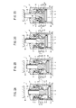
- FIG. 2C It is front sectional drawing which shows the cylinder apparatus with a booster mechanism which concerns on 1st Embodiment, Comprising: It is a figure corresponding to FIG. 2C mentioned later.
- 2A to 2D are operation explanatory views of the cylinder device with a booster mechanism. It is a figure similar to the said FIG. 1 which shows the cylinder apparatus with a booster mechanism concerning 2nd Embodiment.
- FIG. 1 is a front sectional view showing the configuration of the cylinder device 1 with a booster mechanism according to the first embodiment, and corresponds to FIG. 2C described later.
- the cylinder device 1 with a booster mechanism includes a housing 3 having a substantially cylindrical shape.
- the housing 3 has an upper end wall 3a, a lower end wall 3b, and a body portion 3c.
- An inner peripheral surface 10 is formed inside the body 3c of the housing 3.
- a circular lower end surface 11 is formed inside the lower end wall 3 b of the housing 3.
- a through hole 31 is formed in the upper end wall 3a of the housing 3 around the central axis.
- the guide tube 15 protrudes downward from the peripheral wall of the through hole 31.
- An annular upper end surface 22 is formed inside the upper end wall 3 a on the outer peripheral side of the guide tube 15.
- the output rod 2 is inserted into the through hole 31 through the upper sealing member 23 so as to be movable in the central axis direction.
- the lower end of the output rod 2 is connected to the first piston 4.
- the output rod 2 and the first piston 4 may be formed separately and connected to each other.
- "connection" shall include not only the structure which forms two members separately, but connects both, and the structure which forms both integrally.
- the first piston 4 has a disc portion 24 as a piston main body and a column portion 14 as a piston rod integrally projecting upward from the disc portion 24.
- the disk portion 24 is inserted into the inner peripheral surface 10 of the housing 3 through the lower sealing member 26 so as to be able to move in a tight manner.
- the cylindrical portion 14 is formed integrally with the output rod 2.
- a circular pressure receiving surface 5 facing the lower end surface 11 is formed below the disc portion 24.
- the pressure receiving surface 5 has the same shape as the cross section of the housing 3.
- a pressurizing chamber 9 is formed between the lower end wall 3 b of the housing 3 and the pressure receiving surface 5. Between the trunk
- An annular second piston 6 is provided between the guide tube 15 and the body 3c.
- the second piston 6 is provided movably along the outer peripheral surface of the guide tube 15 and the inner peripheral surface 10 of the body portion 3c of the housing 3 via the inner sealing member 17 and the outer sealing member 16, respectively.
- a booster surface 18 is formed on the inner peripheral surface of the second piston 6 so as to move away from the axis of the output rod 2 as it goes downward.
- a push portion 27 is formed at the lower portion of the boost surface 18.
- a driving chamber 12 for moving the second piston 6 downward is formed between the upper end wall 3 a of the housing 3 and the second piston 6.
- a spring 7 for moving the second piston 6 downward is mounted in the drive chamber 12.
- a supply / discharge port 8 communicating with the drive chamber 12 is formed between the upper end wall 3a of the housing 3 and the body portion 3c. Compressed air is supplied to and discharged from the drive chamber 12 via the supply / discharge port 8.
- a release chamber 32 is formed between the first piston 4 and the second piston 6. Compressed air is supplied to and discharged from the release chamber 32 via a supply / discharge path 30 formed in the body 3c of the housing 3 and another supply / discharge port (not shown).
- the guide tube 15 is formed with four support holes 20 penetrating the lower part of the peripheral wall in the radial direction at predetermined intervals in the circumferential direction.
- An engagement ball 21 is inserted into each support hole 20.
- a cam groove 25 is formed on the outer peripheral surface of the cylindrical portion 14 of the first piston 4 so as to correspond to each engagement ball 21.
- the transmission surface 19 formed on the bottom wall of the cam groove 25 is formed so as to approach the axis of the output rod 2 as it goes downward. That is, the transmission surface 19 is formed to have a smaller diameter as it approaches the pressure receiving surface 5.
- An engagement ball 21 can be engaged with the transmission surface 19.
- the booster mechanism M is constituted by the booster surface 18, the support hole 20, the engagement ball 21, and the transmission surface 19. That is, the booster mechanism M is disposed in the release chamber 32.
- FIG. 2A is a front sectional view showing an operating state in a released state (returning drive state) of the cylinder device 1 with a booster mechanism
- FIG. 2B is a front sectional view showing an operating state in an end state of a low load stroke
- 2C is a front sectional view showing an operating state in an initial state of boost driving
- FIG. 2D is a front sectional view showing an operating state in a locked state.
- the housing 3 is fixed to a fixed side member 29 such as a work pallet by a plurality of bolts (not shown).
- the compressed air is discharged from the pressurizing chamber 9 (see FIG. 2B), the compressed air is discharged from the driving chamber 12, and the compressed air is supplied to the release chamber 32. Then, the first piston 4 is lowered and received by the lower end surface 11, and the second piston 6 is raised and received by the upper end surface 22. For this reason, a predetermined gap is formed between the pressing portion 27 of the second piston 6 and the engagement ball 21.
- the second piston 6 tends to descend due to the urging force of the spring 7 and the pressure of the compressed air in the drive chamber 12, but the outer peripheral surface of the cylindrical portion 14 of the first piston 4 causes the engagement ball 21 to have a radius.
- the pushing portion 27 of the second piston 6 is received by the lower wall of the support hole 20 of the guide tube 15 via the engagement ball 21 (that is, the second piston 6 is connected to the guide tube 15). Therefore, the lowering of the second piston 6 is prevented.
- the first piston 4 rises with a low load so as to approach the workpiece W. Specifically, a force based on the pressure of the compressed air in the pressurizing chamber 9 acting on the pressure receiving surface 5 acts on the first piston 4 upward. And since the pushing part 27 of the 2nd piston 6 presses the engagement ball
- the final state of the low-load stroke is a state immediately before the engagement ball 21 starts to engage with the transmission surface 19.
- FIG. 2D representing the locked state
- the first piston 4 is further raised slightly, the upper end of the output rod 2 comes into contact with the workpiece W, and the workpiece W is pressed.
- a margin stroke ⁇ is left on the upper side of the cylindrical portion 14 of the first piston 4.
- the second piston 6 is prevented from rising by the upper end surface 22 of the housing 3.
- the outer peripheral surface of the cylindrical portion 14 of the first piston 4 pushes the engagement ball 21 outward in the radial direction.
- the connected state between the first piston 4 and the second piston 6 is released, and the second piston 6 is received by the guide cylinder 15 via the engagement ball 21, and the second piston 6 is prevented from descending. Is done.
- the first piston 4 further descends with respect to the second piston 6 that is prevented from moving up and down.
- the second piston 6 may be lowered only by the spring 7 without supplying compressed air to the drive chamber 12.
- the supply / discharge port 8 functions as a breathing hole, and the second piston 6 can be moved to the first piston 4 side with a simpler configuration.
- the drive chamber 12 may be configured not to provide the spring 7 but to lower the second piston 6 only by compressed air. In this case, the compressed air for lowering the second piston 6 and the compressed air for raising the first piston 4 can be controlled separately. For this reason, the timing from the low load stroke to the high load stroke can be finely controlled.
- the spring 7 of the driving chamber 12 Since the second piston 6 is urged downward by the spring 7 of the driving chamber 12, even if the pressure in the driving chamber 12 drops or disappears for some reason in the locked state of FIG. 2D, the spring The urging force 7 mechanically holds the locked state through a wedge action by the boost mechanism M (the boost surface 18, the support hole 20, the engagement ball 21, and the transmission surface 19). For this reason, the locked state can be reliably maintained.
- the engagement ball 21 of the booster mechanism M acts directly on the cylindrical portion 14 of the first piston 4 to drive the boost
- the output rod 2 is indirectly boosted.
- the present invention is not limited to this.
- the output rod 2 may be directly boosted by the engagement ball 21.
- the first piston 4 is connected to the output rod 2, and the second piston 6 and the wedge-type booster mechanism M are provided on the output rod side of the first piston 4.
- the pressure receiving surface 5 opposite to the output rod 2 of the first piston 4 is not narrowed by the output rod 2.
- the pressure receiving surface 5 of the first piston 4 can be configured widely. Accordingly, the force based on the pressure fluid acting on the pressure receiving surface 5 of the first piston 4 increases, and the output of the first piston 4 can be increased.
- the pressure receiving area of the pressure receiving surface 5 becomes equal to the cross-sectional area of the inner peripheral surface 10 of the housing 3, the pressure receiving surface 5 of the first piston 4 can be configured wider. Accordingly, the force based on the pressure fluid acting on the pressure receiving surface 5 of the first piston 4 is further increased, and the output of the first piston 4 can be further increased.
- the first piston 4 is received by the end surface 11 facing the pressure receiving surface 5 of the housing 3, and the second piston 6 is received by the end surface 22 facing the second piston 6 of the housing 3. Yes.
- the first piston 4 and the second piston 6 are received by the end surfaces 11 and 22 of the housing 3, respectively. Therefore, unlike the configuration of the conventional Patent Document 2, it is not necessary to form a stopper on the inner peripheral surface 10 of the housing 3 for receiving the first piston 4 and the second piston 6. For this reason, the processing of the housing 3 becomes easy, and the cost of the cylinder device with a booster mechanism can be reduced.
- the first piston 4 has a cylindrical portion 14 formed on the output rod side, a guide cylinder 15 into which the cylindrical portion 14 is inserted is formed in the housing 3, and the second piston 6 is connected to the guide cylinder 15. It moves along the outer peripheral surface and the inner peripheral surface 10 of the housing 3. Since both the outer peripheral surface of the guide cylinder 15 and the inner peripheral surface 10 of the housing 3 are fixed to the housing 3, the second piston 6 can be moved more reliably.
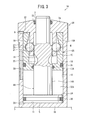
- FIG. 3 is a front sectional view showing the configuration of a cylinder device 1A with a booster mechanism according to the second embodiment.
- the same referential mark is attached
- the cylinder device 1A with a booster mechanism includes a housing 3A.
- the first piston 4 ⁇ / b> A has a disc portion 24 formed so as to be able to move inside the inner peripheral surface 10 of the housing 3 ⁇ / b> A via the lower sealing member 26, and protrudes upward from the disc portion 24 so as to be integrated with the output rod 2.
- a formed cylindrical portion 14A is
- a second piston 6A is provided between the guide tube 15 and the body 3c.
- the second piston 6A is longer than the guide cylinder 15 in the vertical direction.
- the lower end portion of the second piston 6A is configured to be movable with the outer peripheral surface of the cylindrical portion 14A via the inner sealing member 17A, and is movable with the inner peripheral surface 10 of the housing 3A via the outer sealing member 16. It is configured.
- the booster mechanism M including the booster surface 18, the support hole 20, the engagement ball 21, and the transmission surface 19 is arranged in the release chamber 32 in the first embodiment, but in the second embodiment in FIG. As shown, it is disposed in the drive chamber 12A.
- the cylinder device 1A with a booster mechanism also operates in the same manner as the cylinder device 1 with a booster mechanism described in the first embodiment.
- the compressed air is discharged from the pressurizing chamber (not shown), the compressed air is discharged from the drive chamber 12A, and the compressed air is supplied to the release chamber 32A. Then, the first piston 4 ⁇ / b> A descends and is received by the lower end surface 11, and the second piston 6 ⁇ / b> A rises and is received by the upper end surface 22. For this reason, a predetermined gap is formed between the pressing portion 27 of the second piston 6 and the engagement ball 21.
- the second piston 6A tends to descend due to the pressurized pressure of the compressed air in the drive chamber 12A.
- the pushing portion 27 of the second piston 6A is received by the lower wall of the support hole 20 of the guide tube 15 via the engagement ball 21 (that is, the second piston 6A is connected to the guide tube 15). Therefore, the lowering of the second piston 6A is prevented.
- the first piston 4A rises with a low load so as to approach the workpiece.
- the final state of the low load stroke is a state immediately before the engagement ball 21 starts to engage with the transmission surface 19.
- the boost drive When the first piston 4A rises with a low load for a predetermined stroke, the boost drive is in an initial state, and the push portion 27 pushes the engagement ball 21 toward the transmission surface 19 to start the boost drive. Thereby, the connection between the second piston 6A and the guide cylinder 15 (housing 3) is released, and the boosting surface 18 of the second piston 6A moves the first piston 4A through the engagement ball 21 and the transmission surface 19. Begin to rise powerfully. In this case, the pressurizing force of the compressed air supplied to the pressurizing chamber also acts on the first piston 4A via the pressure receiving surface 5, so that the first piston 4A rises more strongly.
- the first piston 4A further slightly rises, the upper end of the output rod 2 contacts the workpiece, and the workpiece is pressed.
- the resultant force of the force acting on the first piston 4A from the second piston 6A via the booster mechanism M and the air pressure acting on the pressure receiving surface 5 of the first piston 4A acts upward, The output rod 2 strongly presses the work.
- a spring for lowering the second piston 6A may be provided.
- a spring may be mounted between the lower end surface of the guide cylinder 15 and the lower portion of the second piston 6A facing the lower end surface.
- the first piston 4A has a cylindrical portion 14A formed on the output rod 2 side, and the second piston 6A moves along the outer peripheral surface of the cylindrical portion 14A and the inner peripheral surface 10 of the housing 3A.
- the pressure receiving surface on the release chamber 32A side of the second piston 6A can be configured more widely.
- the 2nd piston 6A can be moved strongly with compressed air.
- the first piston 4A is received by the lower end surface 11 facing the pressure receiving surface 5 of the housing 3A
- the second piston 6A is received by the upper end surface 22 facing the second piston 6A of the housing 3A. It has been.
- the first piston 4A and the second piston 6A are received by the lower end surface 11 and the upper end surface 22 of the housing 3A, respectively. Therefore, unlike the configuration of the conventional Patent Document 2, it is not necessary to form a stopper for receiving the first piston and the second piston on the inner peripheral surface of the housing. For this reason, processing of a housing becomes easy and the cost of a cylinder device with a booster mechanism can be reduced.
- the above-described embodiments and modifications can be further modified as follows.
- the arrangement posture of the cylinder device 1 with a booster mechanism may be reversed upside down, laterally, or obliquely with respect to the illustrated posture.
- the pressure fluid for use in the cylinder device 1 with a booster mechanism may be a liquid such as pressurized oil instead of the illustrated compressed air.
- the pressure receiving surface 5 of the first piston 4, 4A connected to the output rod 2 and inserted into the housing 3, 3A on the opposite side of the output rod 2 is driven by the pressure fluid, and the first piston 4,
- a wedge-type booster mechanism M arranged on the output rod side of the first pistons 4 and 4A The output rod 2 is boosted.
- the pressure receiving surface of the first piston opposite to the output rod is not narrowed by the output rod. Therefore, the pressure receiving surface of the first piston can be configured widely. Therefore, the force based on the pressure fluid acting on the pressure receiving surface of the first piston increases, and the output of the first piston can be increased.
- the pressure receiving area of the pressure receiving surface 5 is equal to the cross sectional area of the inner peripheral surface 10 of the housings 3 and 3A. According to the said structure, the pressure receiving surface of a 1st piston can be comprised more widely. Therefore, the force based on the pressure fluid acting on the pressure receiving surface of the first piston is further increased, and the output of the first piston can be further increased.
- a spring 7 for moving the second piston 6, 6A toward the first piston it is preferable to provide a spring 7 for moving the second piston 6, 6A toward the first piston.
- the structure which moves a 2nd piston to the said 1st piston side becomes simple.
- the urging force of the spring can hold the second piston and the first piston in a locked state via the wedge-type booster mechanism.
- a supply / discharge port 8 for supplying and discharging the pressure fluid for enabling the second piston 6 and 6A to move and return to the first piston.
- the supply / discharge port for supplying and discharging the pressure fluid for enabling the second piston to move and return to the first piston side is provided, so that the second piston is disposed on the first piston side.
- the pressure fluid for moving the piston and the pressure fluid for driving the pressure receiving surface of the first piston can be controlled separately, and the timing of movement of each piston can be finely controlled.
- the pressurizing chamber 9 to which the pressure fluid for driving the pressure receiving surface 5 is supplied includes the end wall 3b on the first piston side of the both end walls 3a and 3b of the housings 3 and 3A and the pressure receiving surface 5. It is preferable to form between. According to the above configuration, the pressure receiving surface can be driven by the pressure fluid with a simple configuration.
- the drive chambers 12 and 12A for moving the second pistons 6 and 6A to the first piston side are the end walls 3a on the output rod side of the both end walls 3a and 3b of the housings 3 and 3A. And the second piston 6, 6A. According to the above configuration, the second piston can be moved to the first piston side with a simple configuration.
- the first piston 4, 4A faces the pressure receiving surface 5 in the return drive state in which both the first piston 4, 4A and the second piston 6, 6A are moved away from each other.
- the second pistons 6 and 6A are received by the end surfaces 22 of the housings 3 and 3A facing the second pistons 6 and 6A.
- the first piston 4 has a cylindrical portion 14 formed on the output rod side, and a guide cylinder 15 into which the cylindrical portion 14 is inserted is provided in the housing 3.
- the second piston 6 is moved along the outer peripheral surface of the guide tube 15 and the inner peripheral surface 10 of the housing 3. According to the above configuration, since the outer peripheral surface of the guide tube and the inner peripheral surface of the housing are both fixed to the housing, the second piston can be moved more reliably.
- the first piston 4A has a cylindrical portion 14A formed on the output rod side
- the second piston 6A has an outer peripheral surface of the cylindrical portion 14A and the It is preferable to move along the inner peripheral surface 10 of the housing 3A.
- a 2nd piston moves along the outer peripheral surface of the cylindrical part inside a guide cylinder, the pressure receiving surface by the side of the release chamber of a 2nd piston can be comprised more widely. For this reason, the second piston can be moved strongly by the pressure fluid.
- the first pistons 4, 4 ⁇ / b> A have cylindrical portions 14, 14 ⁇ / b> A formed on the output rod side, and the wedge-type booster mechanism M approaches the output rod as it approaches the pressure receiving surface 5. And the cylindrical surface portions 14 and 14A so as to approach the axial center of the output rod 2 as the pressure receiving surface 5 is approached.
- positions a wedge type booster mechanism in the rod side of a 1st piston becomes simple.
- the wedge-type booster mechanism M is an engagement ball 21 mounted between one of the first pistons 4 and 4A and the output rod 2 and the second pistons 6 and 6A. And a plurality of engagement balls 21 arranged at predetermined intervals in the circumferential direction around the axis of the first pistons 4 and 4A, and the engagement balls 21 include the second piston 6, A state in which 6A is prevented from moving toward the first piston 4, 4A and the first piston 4, 4A and the output rod 2 are moved toward the second piston 6, 6A; , 6A is moved to the first piston 4, 4A side, and the second piston 6, 6A doubles the first piston 4, 4A and the output rod 2 to the second piston 6, 6A side. Can be switched to It is preferable that the formed. According to the above configuration, it is possible to reliably and smoothly switch between the state where the boost driving is performed and the state where the boost driving is not performed.
Landscapes
- Engineering & Computer Science (AREA)
- Physics & Mathematics (AREA)
- Fluid Mechanics (AREA)
- Mechanical Engineering (AREA)
- General Engineering & Computer Science (AREA)
- Actuator (AREA)
Priority Applications (2)
| Application Number | Priority Date | Filing Date | Title |
|---|---|---|---|
| US14/430,247 US10024340B2 (en) | 2012-10-01 | 2013-09-26 | Cylinder device with force multiplication mechanism |
| EP13844228.0A EP2905481B1 (en) | 2012-10-01 | 2013-09-26 | Cylinder device with force multiplication mechanism |
Applications Claiming Priority (2)
| Application Number | Priority Date | Filing Date | Title |
|---|---|---|---|
| JP2012219707A JP5939950B2 (ja) | 2012-10-01 | 2012-10-01 | 倍力機構付きシリンダ装置 |
| JP2012-219707 | 2012-10-01 |
Publications (1)
| Publication Number | Publication Date |
|---|---|
| WO2014054503A1 true WO2014054503A1 (ja) | 2014-04-10 |
Family
ID=50434831
Family Applications (1)
| Application Number | Title | Priority Date | Filing Date |
|---|---|---|---|
| PCT/JP2013/076120 Ceased WO2014054503A1 (ja) | 2012-10-01 | 2013-09-26 | 倍力機構付きシリンダ装置 |
Country Status (4)
| Country | Link |
|---|---|
| US (1) | US10024340B2 (enExample) |
| EP (1) | EP2905481B1 (enExample) |
| JP (1) | JP5939950B2 (enExample) |
| WO (1) | WO2014054503A1 (enExample) |
Cited By (2)
| Publication number | Priority date | Publication date | Assignee | Title |
|---|---|---|---|---|
| CN107269622A (zh) * | 2017-07-31 | 2017-10-20 | 山东万通液压股份有限公司 | 自适应式活塞杆与活塞连接结构 |
| JP2021133437A (ja) * | 2020-02-25 | 2021-09-13 | 株式会社コスメック | 倍力機構付きシリンダ装置 |
Families Citing this family (2)
| Publication number | Priority date | Publication date | Assignee | Title |
|---|---|---|---|---|
| JP6353782B2 (ja) * | 2014-12-25 | 2018-07-04 | 株式会社コスメック | 倍力機構付きシリンダ装置 |
| CN105545858B (zh) * | 2016-02-03 | 2017-06-23 | 山东科技大学 | 一种气‑液增压缸专用气控阀及气‑液增压缸 |
Citations (9)
| Publication number | Priority date | Publication date | Assignee | Title |
|---|---|---|---|---|
| JPS5430374A (en) * | 1977-08-10 | 1979-03-06 | Harunobu Nishioka | Boosting device |
| JPH01171903U (enExample) * | 1988-05-26 | 1989-12-06 | ||
| JPH0642507A (ja) * | 1992-07-20 | 1994-02-15 | Akio Matsui | 増圧型流体圧シリンダ |
| JPH11166506A (ja) * | 1997-12-01 | 1999-06-22 | Smc Corp | 流体圧シリンダ |
| JPH11173307A (ja) * | 1997-12-09 | 1999-06-29 | Ihara Science Corp | 小型アクチュエータ用倍力機構 |
| JP2001025932A (ja) | 1999-07-12 | 2001-01-30 | Sankyo Seiki Mfg Co Ltd | 工具ホルダ把持機構 |
| JP2008116032A (ja) * | 2006-11-01 | 2008-05-22 | Pubot Giken:Kk | 増力型流体圧シリンダ |
| JP2009255219A (ja) * | 2008-04-16 | 2009-11-05 | Pascal Engineering Corp | クランプ装置 |
| JP4945681B1 (ja) | 2010-11-24 | 2012-06-06 | 株式会社コスメック | 倍力機構付きシリンダ装置 |
Family Cites Families (7)
| Publication number | Priority date | Publication date | Assignee | Title |
|---|---|---|---|---|
| CH665007A5 (de) * | 1984-05-11 | 1988-04-15 | Enfo Grundlagen Forschungs Ag | Hydraulischer zylinder mit kraftmultiplikation. |
| JPS6267309A (ja) * | 1985-09-20 | 1987-03-27 | Mikado Kinzoku Kogyo Kk | 大ストロ−ク用エアシリンダ |
| DE69208435T2 (de) | 1991-12-13 | 1996-07-04 | Akio Gifu Gifu Matsui | Druckflüssigkeitszylinder mit Druckübersetzer |
| JP2002096231A (ja) * | 2000-09-22 | 2002-04-02 | Kosmek Ltd | クランプ装置 |
| JP5430374B2 (ja) | 2009-12-04 | 2014-02-26 | 株式会社ダスキン | 油ポット |
| JP2012112532A (ja) * | 2012-02-13 | 2012-06-14 | Kosmek Ltd | 倍力機構付きシリンダ装置 |
| JP6267309B2 (ja) | 2016-11-09 | 2018-01-24 | シャープ株式会社 | 蒸気調理器 |
-
2012
- 2012-10-01 JP JP2012219707A patent/JP5939950B2/ja active Active
-
2013
- 2013-09-26 EP EP13844228.0A patent/EP2905481B1/en active Active
- 2013-09-26 WO PCT/JP2013/076120 patent/WO2014054503A1/ja not_active Ceased
- 2013-09-26 US US14/430,247 patent/US10024340B2/en active Active
Patent Citations (9)
| Publication number | Priority date | Publication date | Assignee | Title |
|---|---|---|---|---|
| JPS5430374A (en) * | 1977-08-10 | 1979-03-06 | Harunobu Nishioka | Boosting device |
| JPH01171903U (enExample) * | 1988-05-26 | 1989-12-06 | ||
| JPH0642507A (ja) * | 1992-07-20 | 1994-02-15 | Akio Matsui | 増圧型流体圧シリンダ |
| JPH11166506A (ja) * | 1997-12-01 | 1999-06-22 | Smc Corp | 流体圧シリンダ |
| JPH11173307A (ja) * | 1997-12-09 | 1999-06-29 | Ihara Science Corp | 小型アクチュエータ用倍力機構 |
| JP2001025932A (ja) | 1999-07-12 | 2001-01-30 | Sankyo Seiki Mfg Co Ltd | 工具ホルダ把持機構 |
| JP2008116032A (ja) * | 2006-11-01 | 2008-05-22 | Pubot Giken:Kk | 増力型流体圧シリンダ |
| JP2009255219A (ja) * | 2008-04-16 | 2009-11-05 | Pascal Engineering Corp | クランプ装置 |
| JP4945681B1 (ja) | 2010-11-24 | 2012-06-06 | 株式会社コスメック | 倍力機構付きシリンダ装置 |
Cited By (3)
| Publication number | Priority date | Publication date | Assignee | Title |
|---|---|---|---|---|
| CN107269622A (zh) * | 2017-07-31 | 2017-10-20 | 山东万通液压股份有限公司 | 自适应式活塞杆与活塞连接结构 |
| JP2021133437A (ja) * | 2020-02-25 | 2021-09-13 | 株式会社コスメック | 倍力機構付きシリンダ装置 |
| JP7437741B2 (ja) | 2020-02-25 | 2024-02-26 | 株式会社コスメック | 倍力機構付きシリンダ装置 |
Also Published As
| Publication number | Publication date |
|---|---|
| JP5939950B2 (ja) | 2016-06-22 |
| EP2905481B1 (en) | 2018-01-17 |
| EP2905481A4 (en) | 2015-10-14 |
| US20150247512A1 (en) | 2015-09-03 |
| EP2905481A1 (en) | 2015-08-12 |
| JP2014070722A (ja) | 2014-04-21 |
| US10024340B2 (en) | 2018-07-17 |
Similar Documents
| Publication | Publication Date | Title |
|---|---|---|
| CN103688065B (zh) | 带增力机构的压缸装置 | |
| JP4945681B1 (ja) | 倍力機構付きシリンダ装置 | |
| CN104105890B (zh) | 带助力机构的缸装置 | |
| JP5939950B2 (ja) | 倍力機構付きシリンダ装置 | |
| KR20160142278A (ko) | 클램프 장치 | |
| JP6026856B2 (ja) | 倍力機構付きシリンダ装置 | |
| JP5750187B2 (ja) | 倍力機構付きシリンダ装置 | |
| JP4720401B2 (ja) | 増圧型流体圧シリンダ | |
| KR100775687B1 (ko) | 클램프 장치 | |
| JP5734264B2 (ja) | 倍力機構付きシリンダ装置 | |
| JP5760125B2 (ja) | 倍力機構付きシリンダ装置 | |
| JP2002096231A (ja) | クランプ装置 | |
| JP5750089B2 (ja) | 倍力機構付きシリンダ装置 | |
| JP5632902B2 (ja) | 倍力機構付きシリンダ装置 | |
| JP5837857B2 (ja) | 倍力機構付きシリンダ装置 | |
| JP6353782B2 (ja) | 倍力機構付きシリンダ装置 | |
| JP2013151963A (ja) | 倍力機構付きシリンダ装置 | |
| TWI724235B (zh) | 附倍力機構的壓缸裝置 | |
| JP2012112532A (ja) | 倍力機構付きシリンダ装置 | |
| JP5043243B2 (ja) | 倍力機構付きシリンダ装置 | |
| JP2025082134A (ja) | 倍力機構付きシリンダ装置 | |
| JP2016109284A (ja) | 倍力機構付きシリンダ装置 |
Legal Events
| Date | Code | Title | Description |
|---|---|---|---|
| 121 | Ep: the epo has been informed by wipo that ep was designated in this application |
Ref document number: 13844228 Country of ref document: EP Kind code of ref document: A1 |
|
| WWE | Wipo information: entry into national phase |
Ref document number: 2013844228 Country of ref document: EP |
|
| WWE | Wipo information: entry into national phase |
Ref document number: 14430247 Country of ref document: US |
|
| NENP | Non-entry into the national phase |
Ref country code: DE |