WO2014054401A1 - キャップ付容器 - Google Patents
キャップ付容器 Download PDFInfo
- Publication number
- WO2014054401A1 WO2014054401A1 PCT/JP2013/074669 JP2013074669W WO2014054401A1 WO 2014054401 A1 WO2014054401 A1 WO 2014054401A1 JP 2013074669 W JP2013074669 W JP 2013074669W WO 2014054401 A1 WO2014054401 A1 WO 2014054401A1
- Authority
- WO
- WIPO (PCT)
- Prior art keywords
- container
- cap
- inner plug
- plug body
- engagement
- Prior art date
- Legal status (The legal status is an assumption and is not a legal conclusion. Google has not performed a legal analysis and makes no representation as to the accuracy of the status listed.)
- Ceased
Links
Images


Classifications
-
- B—PERFORMING OPERATIONS; TRANSPORTING
- B65—CONVEYING; PACKING; STORING; HANDLING THIN OR FILAMENTARY MATERIAL
- B65D—CONTAINERS FOR STORAGE OR TRANSPORT OF ARTICLES OR MATERIALS, e.g. BAGS, BARRELS, BOTTLES, BOXES, CANS, CARTONS, CRATES, DRUMS, JARS, TANKS, HOPPERS, FORWARDING CONTAINERS; ACCESSORIES, CLOSURES, OR FITTINGS THEREFOR; PACKAGING ELEMENTS; PACKAGES
- B65D47/00—Closures with filling and discharging, or with discharging, devices
- B65D47/04—Closures with discharging devices other than pumps
- B65D47/06—Closures with discharging devices other than pumps with pouring spouts or tubes; with discharge nozzles or passages
- B65D47/12—Closures with discharging devices other than pumps with pouring spouts or tubes; with discharge nozzles or passages having removable closures
- B65D47/122—Threaded caps
- B65D47/123—Threaded caps with internal parts
-
- B—PERFORMING OPERATIONS; TRANSPORTING
- B65—CONVEYING; PACKING; STORING; HANDLING THIN OR FILAMENTARY MATERIAL
- B65D—CONTAINERS FOR STORAGE OR TRANSPORT OF ARTICLES OR MATERIALS, e.g. BAGS, BARRELS, BOTTLES, BOXES, CANS, CARTONS, CRATES, DRUMS, JARS, TANKS, HOPPERS, FORWARDING CONTAINERS; ACCESSORIES, CLOSURES, OR FITTINGS THEREFOR; PACKAGING ELEMENTS; PACKAGES
- B65D47/00—Closures with filling and discharging, or with discharging, devices
- B65D47/04—Closures with discharging devices other than pumps
- B65D47/06—Closures with discharging devices other than pumps with pouring spouts or tubes; with discharge nozzles or passages
- B65D47/10—Closures with discharging devices other than pumps with pouring spouts or tubes; with discharge nozzles or passages having frangible closures
- B65D47/103—Membranes with a tearing element
Definitions
- the present invention relates to a container with a cap, and is a container with a cap in which an inner stopper is fitted to a container mouth portion, and a cap is attached to and detached from a screw portion formed in the inner stopper, and the inner stopper is a cap when the cap is attached / detached. It is designed to be securely attached and detached without having to go around.
- a container with a cap provided with a cap that can be attached and detached with a screw is used as a container for liquid foods such as dressing.
- the container with a cap 1 is made of glass or synthetic resin.
- An inner plug body 3 provided with a spout 3a made of synthetic resin is plugged into a mouth portion 2a of a container 2 such as a product, and the screw section 4a of the cap 4 is screwed into a screw section 3b formed on the inner plug body 3.
- the cap 4 can be attached and detached (see Patent Document 1).
- the outer peripheral surface of the mouth portion 2 a of the container 2 is formed in an annular shape so that the engaging peripheral strip 5 protrudes outward in order to fix and hold the inner plug body 3 to be plugged.
- a neck ring 2b is formed in an annular shape below the neck ring 2b.
- the inner plug body 3 is provided with a spout 3a surrounded by a thinned breaking groove 3d in the partition wall 3c, so that the spout 3a can be opened by pulling up the pull ring 3e during use.
- a pour cylinder 3f is formed by projecting upward so as to surround the pour port 3a, and a screw portion 3b for the cap 4 is formed on the outer periphery of the pour cylinder 3f. Further, the outer peripheral portion of the partition wall 3c of the inner plug body 3 is protruded downward to form inner and outer peripheral walls 3g and 3h. The inner peripheral surface of the outer peripheral wall 3h is engaged with the engagement peripheral strip 5 of the container 2.
- the engaging protrusion 6 to be joined protrudes inward and is formed into an annular shape, and the inner plug 3 is engaged with the engaging peripheral line 5 of the container 2 with the inner plug 3 being plugged into the mouth 2a of the container 2. The mating ridge 6 is engaged so that the fitted state can be maintained.
- the locking protrusion 7 of the container 2 and the locking groove 8 of the inner plug body 3 are positioned and plugged in advance or without positioning.
- the cap 4 is rotated when the consumer uses it for the first time, and the locking protrusion 7 and the locking groove 8 are locked.
- the cap 4 can be attached to and detached from the threaded portion 3b of the inner plug 3 without being locked by the container 2 and rotating together.
- the present invention has been made in view of the present situation.
- the inner plug body is fitted to the container mouth portion and the cap screwed into the screw portion formed in the inner plug body is attached and detached, the inner plug body and the cap are provided. Is intended to provide a container with a cap that can be attached and detached without rotating together.
- a container with a cap according to claim 1 of the present invention comprises an inner plug fitted into the mouth of the container and a cap detachably screwed into the inner plug.
- a container with a cap provided, The container is provided with an engagement peripheral line that protrudes on the outer peripheral surface of the mouth portion, and protrudes on the peripheral surface of the engagement peripheral line to stop the inner plug body from rotating.
- the inner plug body is formed with a screw portion to which the cap is attached and detached, and is provided with an outer peripheral wall fitted to the outer peripheral surface of the container mouth portion, and the inner peripheral surface of the outer peripheral wall is provided with the container While an engagement protrusion that is engaged with the engagement periphery and maintains the fitted state, and an engagement groove that is engaged with the engagement protrusion, When the inner plug and the container mouth are engaged, a built-up portion is formed in the locking groove below the locking protrusion.
- the protruding height of the build-up portion is 0.8 to 1.2 times the protruding height of the engaging protrusion. It is characterized in that it is formed.
- the cap-equipped container according to claim 3 of the present invention is characterized in that, in addition to the configuration according to claim 1 or 2, the build-up portion has a shape that can be engaged with the lower end of the locking protrusion. Is.
- the rigidity of the locking groove itself and the outer wall portion of the inner plug body can be increased, and the locking protrusion can be reliably engaged with the locking protrusion. It can stop and the anti-rotation effect can be improved. Further, it is possible to prevent the tip corner portion of the locking groove from being turned up during the mold release. Furthermore, by increasing the thickness of the locking groove, it is possible to improve the ESC resistance effect (environmental stress cracking resistance) due to the contents and the like, and it is possible to expand the selection range of materials and the like.
- the engagement holding force is obtained by engaging the build-up portion with the engagement protrusion even in the engagement groove portion having no engagement protrusion for retaining the attachment.
- the inner plug body can be securely fixed and held.
- FIG. 1 is a schematic cross-sectional view according to an embodiment of a container with a cap of the present invention
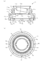
- FIG. It is an inside stopper object concerning one embodiment of a container with a cap of this invention
- (a) is a sectional view
- (b) is a bottom view
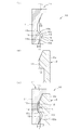
- 1 is an enlarged view of a part of an embodiment of a container with a cap according to the present invention, wherein (a) is a sectional view of an inner plug, (b) is a sectional view of the container, and (c) is a sectional view in a fitted state.
- It is.
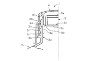
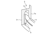
- It is a schematic sectional drawing of a container with a cap. It is the schematic perspective view which expanded a part of conventional container with a cap.
- FIG. 2 is an enlarged view of a portion of a conventional container with a cap, in which (a) is a sectional view and AA sectional view of an inner plug body, (b) is a sectional view of the container, and (c) is a sectional view in a fitted state. is there.
- the container 10 with a cap has the same basic structure as the container 1 with a cap already described with reference to FIG. 4, and instead of the inner plug body 3, it is made of glass or synthetic resin as shown in FIG.
- an inner plug body 11 having a spout 11 a made of a synthetic resin is plugged into the mouth portion 2 a of the container 2.
- the cap 4 can be attached and detached by screwing the screw part 4a of the cap 4.
- the fixed state is expressed separately, so the case where the inner plug body 11 and the mouth portion 2a are in the stoppered state is expressed as “engagement” for preventing co-rotation.
- the case of holding is expressed as “locking”.
- an engagement peripheral strip 12 is formed in an annular shape so as to protrude outward in order to fix and hold the plug 11 to be plugged.
- the engagement circumferential strip 12 of the container 2 is an inclined surface (conical surface) whose outer peripheral surface extends downward from above, its lower end is a horizontal plane, and the inner plug 11 is engaged at the corner between the inclined plane and the horizontal plane.
- the mating ridge 13 is engaged.
- the inner plug body 11 is provided with a spout 11a surrounded by a thin fracture groove 11d in the central partition plate 11c, and the pull-out ring 11e is pulled up during use so that the spout 11a can be opened.
- a pour tube 11f is formed so as to project upward so as to surround the pour port 11a, and guides the pour of the contents.
- An intermediate part partition plate 11g is formed horizontally on the outer periphery of the middle part of the pouring cylinder 11f, and a screw cylinder 11h is formed on the outer periphery of the intermediate part partition plate 11g so as to protrude downward.
- the screw part 11b for the cap 4 is formed on the outer periphery of the screw cylinder 11h.
- the inner plug body 11 is formed with an outer peripheral partition plate 11i horizontally at the lower end portion of the screw cylinder 11h, and an outer peripheral wall 11j is formed on the outer peripheral portion of the outer peripheral partition plate 11i so as to protrude downward.
- An inner peripheral wall 11k is formed on the inner peripheral portion of the outer peripheral partition plate 11i to form a double cylinder, and the mouth portion 2a of the container 2 is positioned between the outer peripheral wall 11j and the inner peripheral wall 11k.
- the upper end surface of 2a is fitted on the outer peripheral partition plate 11i.
- an engagement protrusion 13 that engages with the engagement periphery 12 of the container 2 protrudes inwardly on the inner peripheral surface of the outer peripheral wall 11j of the inner plug body 11 to form a substantially annular shape (a locking groove 15 portion described later).
- the engagement protrusion 13 of the inner plug body 11 is engaged with the engagement peripheral line 12 of the container 2 in a state where the inner plug body 11 is plugged into the mouth portion 2a of the container 2, and is fitted. Can be held.
- the engagement protrusion 13 of the inner plug body 11 has, for example, an upper inclined surface having a large inclination angle in the central axis direction and a lower portion having a small inclination angle in the central axis direction.
- the lower inclined surface has a substantially hook shape so as to be smoothly continuous with the protruding portion interposed therebetween, and the protruding portion and the upper inclined surface above the protruding portion are brought into line contact with the engaging circumferential stripe 12 and locked. is there.
- a detent in the container 10 with a cap as shown in FIGS. 1 to 3, a plurality of vertical locking protrusions 14 are formed on the outer periphery of the engaging peripheral strip 12 of the mouth 2a of the container 2. .
- a locking groove 15 that locks with the locking protrusion 14 is formed in the inner plug body 11 on the inner peripheral surface of the outer peripheral wall 11j so as to reach the engaging protrusion 13 in the vertical direction.
- the number of the locking grooves 15 may be the same as the number of the locking protrusions 14 or a different number. Further, all the locking protrusions 14 and the locking grooves 15 may be locked, or a part of the locking protrusions 14 and the locking grooves 15 may be locked. good.
- the built-up portion 16 is formed below the lower end portion 15c of the locking groove 15 which is a portion to which the locking protrusion 14 is locked. It is.
- the build-up portion 16 of the locking groove 15 includes a groove bottom portion (bottom portion of the outer peripheral groove in the inner plug body 11) 15a and both groove side portions (circumferential direction in the inner plug body 11).
- the left and right side surface portions 15b are continuously formed with the built-up portion 16, and the built-up portion 16 is formed to protrude to the center side of the inner plug body 11, and when the inner plug body 11 is engaged, It is located below the lower end of the locking protrusion 14 of the container 2.
- the upper portion of the locking groove 15 is a groove having a rectangular cross section so that the locking protrusion 14 can be locked, and the built-up portion 16 protrudes below the locking groove 15.
- the built-up portion 16 is engaged so as to get over the locking protrusion 14, and the locking protrusion 14 and the locking groove 15 Will be locked.
- the locking groove 15 (at least a part below the lower end part 15c) other than the part where the locking protrusion 14 is locked is reinforced by the built-up part 16, and
- the locking groove 15 itself and the outer wall portion 11j of the inner plug body 11 are not easily extended and spread. That is, even if the locking groove 15 is formed in the outer peripheral wall 11j of the inner plug body 11 with respect to the locking groove 8 (see FIGS. 5 and 6) having a flat bottom, the locking groove 15 itself and the inner plug body 11 can secure the rigidity of the outer wall portion 11j, and can be securely locked to the locking projection piece 14 to improve the anti-rotation effect. According to experiments, it has been confirmed that the anti-rotation effect is improved by 5 to 40% in rotational torque, although it depends on the material of the inner plug body 11.
- the thin wall portion of the inner plug body 11 is reduced, so that the locking groove 15 itself and the outer wall portion 11 j of the inner plug body 11 are extended.
- the protruding height of the built-up portion 16 of the locking groove 15, that is, the height (building height) H from the groove bottom portion 15a of the locking groove 15 is the engagement protrusion from the inner peripheral surface of the outer peripheral wall 11j.
- the protrusion height h of 13 is 0.8 to 1.2 times.
- the protruding height H of the built-up portion 16 can be up to the same height as the engaging protrusion 13 of the outer peripheral wall 11j of the inner plug body 11 in which the locking groove 15 is formed. In this case, the built-up portion 16, the lower side of the locking groove 15 is filled, and the effect of reinforcing and improving rigidity is increased by building up as much as possible.
- the engaging protrusions 13 and the built-up portions 16 of the inner plug body 11 are undercut in the molding of the synthetic resin, and are removed by using the elastic deformation of the synthetic resin at the time of mold release. Therefore, the higher the height H of the built-up portion 16, the more difficult it is to release. On the other hand, if the protruding height H of the built-up portion 16 is too low, the rigidity cannot be improved due to the built-up.
- the protruding height H of the built-up portion 16 of the locking groove 15 is set to 0.8 to 1... Of the protruding height h of the engaging protrusion 13 from the inner peripheral surface of the outer peripheral wall 11j.
- the rigidity of the inner plug body 11 is improved, and at the same time, the inner plug body 11 expands due to the undercut in the mold release of the inner plug body 11, but the locking groove 15 also has an engagement protrusion. It spreads almost as much as the undercut part of the strip 13, so that only a part is loaded and stress is not concentrated, it can be molded into a predetermined shape, and the tip corner 13a of the engaging projection 13 is prevented from turning over. You can also Thereby, the latching protrusion 14 and the latching groove
- channel 15 can be latched reliably, and the co-rotation with the cap 4 and the inside plug body 11 can be prevented more reliably.
- the built-up portion 16 of the locking groove 15 has a shape that can be engaged with the lower end of the locking protrusion 14, and there is no locking protrusion 13 for holding the fitting.
- the shape of the build-up portion 16 is preferably a shape that can be engaged with and locked to the lower end of the locking projection piece 14, and an inclined surface (conical surface) in which the outer peripheral surface of the locking projection piece 14 extends downward from above.
- the lower end surface is a horizontal plane, for example, as shown in FIG.
- the corner portion at the lower end of the outer periphery of the locking projection 14 and the inclined surface above the built-up portion 16 are engaged with each other, and the engagement between the engagement ridge 12 and the engagement ridge 13 is engaged.
- the fitting state of the inner plug 11 to the container 2 is more reliably maintained.
- the description of the synthetic resin constituting the inner plug is omitted, but commonly used polyethylene, polypropylene, or the like can be used.
- the container may be made of a commonly used material such as glass, PET, or polypropylene.
- a screw portion may be provided on the outer periphery of the extraction cylinder as shown in FIG.
Landscapes
- Engineering & Computer Science (AREA)
- Mechanical Engineering (AREA)
- Closures For Containers (AREA)
Description
この発明は、キャップ付容器に関し、容器口部に中栓体を嵌着し、中栓体に形成したねじ部にキャップを着脱するキャップ付容器で、キャップの着脱の際に中栓体がキャップと共廻りせずに確実に着脱できるようにしたものである。
ドレッシングなどの液状食品などの容器のひとつとしてねじにより着脱し密封できるキャップを備えたキャップ付容器が用いられており、例えば図4に示すように、このキャップ付容器1では、ガラス製や合成樹脂製などの容器2の口部2aに合成樹脂製の注出口3aを備えた中栓体3を打栓嵌着し、中栓体3に形成したねじ部3bにキャップ4のねじ部4aをねじ込むことで、キャップ4の着脱が可能とされている(特許文献1参照)。
このようなキャップ付き容器1では、容器2の口部2aの外周面には、打栓される中栓体3を固定保持するため係合周条5が外側に突き出すように環状に形成されるとともに、その下方にネックリング2bが環状に形成されている。
一方、中栓体3には、仕切壁3cに薄肉とされた破断溝3dで囲まれて注出口3aが設けられ、プルリング3eを使用時に引き上げることで、注出口3aを開口できるようにしてあり、注出口3aを囲むように上方に突き出して注出筒3fが形成され、この注出筒3fの外周にキャップ4用のねじ部3bが形成してある。
また、中栓体3の仕切壁3cの外周部には、下方に突き出して内外周壁3g,3hが形成してあり、外周壁3hの内周面に、容器2の係合周条5と係合される係合突条6が内側に突き出して環状に形成され、容器2の口部2aに中栓体3を打栓した状態で容器2の係合周条5に中栓体3の係合突条6が係合され、嵌着状態を保持できるようにしてある。
このようなキャップ付き容器1では、容器2の口部2aの外周面には、打栓される中栓体3を固定保持するため係合周条5が外側に突き出すように環状に形成されるとともに、その下方にネックリング2bが環状に形成されている。
一方、中栓体3には、仕切壁3cに薄肉とされた破断溝3dで囲まれて注出口3aが設けられ、プルリング3eを使用時に引き上げることで、注出口3aを開口できるようにしてあり、注出口3aを囲むように上方に突き出して注出筒3fが形成され、この注出筒3fの外周にキャップ4用のねじ部3bが形成してある。
また、中栓体3の仕切壁3cの外周部には、下方に突き出して内外周壁3g,3hが形成してあり、外周壁3hの内周面に、容器2の係合周条5と係合される係合突条6が内側に突き出して環状に形成され、容器2の口部2aに中栓体3を打栓した状態で容器2の係合周条5に中栓体3の係合突条6が係合され、嵌着状態を保持できるようにしてある。
このようなキャップ付容器1では、キャップ4を回転する際にキャップ4と中栓体3が共回りするとキャップ4の着脱開閉ができなくなることから回り止めが設けられている。
キャップ付容器1の回り止めとしては、例えば特許文献1に開示されたものがあり、図5および図6に示すように、容器2の口部2aの係合周条5の外周に縦方向の係止突片7を複数形成しておき、中栓体3には、打栓嵌着される外周壁3hの内側に係合突条6にまで達する縦方向の係止溝8を形成する。そして、容器2への中栓体3の打栓の際、容器2の係止突片7と中栓体3の係止溝8とを予め位置決めして打栓するか、あるいは位置決めせずに打栓して、消費者が最初に使用する際にキャップ4を回転させ、係止突片7と係止溝8とを係止することで、キャップ4を回転した際に中栓体3が容器2に係止されて共回りすることなくキャップ4を中栓体3のねじ部3bから着脱できるようにしている。
キャップ付容器1の回り止めとしては、例えば特許文献1に開示されたものがあり、図5および図6に示すように、容器2の口部2aの係合周条5の外周に縦方向の係止突片7を複数形成しておき、中栓体3には、打栓嵌着される外周壁3hの内側に係合突条6にまで達する縦方向の係止溝8を形成する。そして、容器2への中栓体3の打栓の際、容器2の係止突片7と中栓体3の係止溝8とを予め位置決めして打栓するか、あるいは位置決めせずに打栓して、消費者が最初に使用する際にキャップ4を回転させ、係止突片7と係止溝8とを係止することで、キャップ4を回転した際に中栓体3が容器2に係止されて共回りすることなくキャップ4を中栓体3のねじ部3bから着脱できるようにしている。
ところが、このようなキャップ付容器1では、使用開始後、内容物のねじ部3bへの付着・固化などによってキャップ4と中栓体3とが固着した場合、キャップ4を開ける際に中栓体3の係止溝8が係止突片7を乗り越えキャップ4と共回りする場合があり、さらなる対策が求められているのが現状である。
この発明はかかる現状に鑑みてなされたもので、容器口部に中栓体を嵌着し、中栓体に形成したねじ部にねじ込まれたキャップの着脱を行う際に、中栓体とキャップが共回りせずに着脱できるキャップ付容器を提供しようとするものである。
上記従来技術が有する課題を解決するためこの発明の請求項1記載のキャップ付容器は、容器の口部に嵌着される中栓体と、この中栓体に着脱可能にねじ込まれるキャップとを備えたキャップ付容器であって、
前記容器には、口部外周面に嵌着状態を保持する係合周条が突き出して設けられるとともに、前記係合周条の周面上に突き出して前記中栓体回り止め用の係止突片が形成され、
前記中栓体には、前記キャップが着脱されるねじ部が形成されるとともに、前記容器口部の外周面に嵌着される外周壁が設けられ、外周壁の内周面には、前記容器の係合周条に係合されて嵌着状態を保持する係合突条と、前記係止突片と係止される係止溝とが形成される一方、
前記中栓体と前記容器口部が係合した際、前記係止突片より下側の前記係止溝に肉盛部を形成したことを特徴とするものである。
前記容器には、口部外周面に嵌着状態を保持する係合周条が突き出して設けられるとともに、前記係合周条の周面上に突き出して前記中栓体回り止め用の係止突片が形成され、
前記中栓体には、前記キャップが着脱されるねじ部が形成されるとともに、前記容器口部の外周面に嵌着される外周壁が設けられ、外周壁の内周面には、前記容器の係合周条に係合されて嵌着状態を保持する係合突条と、前記係止突片と係止される係止溝とが形成される一方、
前記中栓体と前記容器口部が係合した際、前記係止突片より下側の前記係止溝に肉盛部を形成したことを特徴とするものである。
この発明の請求項2記載のキャップ付容器は、請求項1記載の構成に加え、前記肉盛部の突き出し高さを、前記係合突条の突き出し高さの0.8~1.2倍に形成したことを特徴とするものである。
この発明の請求項3記載のキャップ付容器は、請求項1または2記載の構成に加え、前記肉盛部を、前記係止突片の下端に係合可能な形状としたことを特徴とするものである。
この発明の請求項1記載のキャップ付容器によれば、係止溝を形成しても係止溝自体および中栓体の外壁部の剛性を高めることができ、係止突片と確実に係止して回り止め効果を向上することができる。また、係止溝の先端角部が成形離型の際にめくれることなども防止することができる。
さらに、係止溝の肉厚が増大されることで、内容物などによる耐ESC効果(耐環境応力割れ)の向上を図ることができ、材料などの選択範囲を拡大することもできる。
さらに、係止溝の肉厚が増大されることで、内容物などによる耐ESC効果(耐環境応力割れ)の向上を図ることができ、材料などの選択範囲を拡大することもできる。
この発明の請求項2記載のキャップ付容器によれば、より効果的にめくれなどの発生を防止することができる。
この発明の請求項3記載のキャップ付容器によれば、嵌着保持用の係合突条がない係止溝部分でも係止突片に肉盛部を係合することで、嵌着保持力を一層高めることができ、中栓体を確実に固定保持することができる。
以下、この発明のキャップ付き容器の一実施の形態について図面に基づき詳細に説明する。
このキャップ付容器10は、既に図4により説明したキャップ付容器1と基本的な構造が同一とされ、中栓体3に換えて、図1(a)に示したガラス製や合成樹脂製などの容器2の口部2aに、図1~3に示すように,合成樹脂製の注出口11aを備えた中栓体11を打栓嵌着し、中栓体11に形成したねじ部11bにキャップ4のねじ部4aをねじ込むことで、キャップ4の着脱が可能とされたものであるが、中栓体11の容器2に対する回り止めのための構造を変えることで、キャップ4を着脱する際のキャップ4と中栓体11との共回り防止効果を向上できるようにしたものである。
なお、明細書中、固定状態を区分けして表現するため、中栓体11と口部2aとの打栓嵌着状態の保持の場合を「係合」と表現し、共回り防止のための保持の場合を「係止」と表現する。
このキャップ付容器10は、既に図4により説明したキャップ付容器1と基本的な構造が同一とされ、中栓体3に換えて、図1(a)に示したガラス製や合成樹脂製などの容器2の口部2aに、図1~3に示すように,合成樹脂製の注出口11aを備えた中栓体11を打栓嵌着し、中栓体11に形成したねじ部11bにキャップ4のねじ部4aをねじ込むことで、キャップ4の着脱が可能とされたものであるが、中栓体11の容器2に対する回り止めのための構造を変えることで、キャップ4を着脱する際のキャップ4と中栓体11との共回り防止効果を向上できるようにしたものである。
なお、明細書中、固定状態を区分けして表現するため、中栓体11と口部2aとの打栓嵌着状態の保持の場合を「係合」と表現し、共回り防止のための保持の場合を「係止」と表現する。
このキャップ付容器10では、容器2の口部2aの外周面には、打栓される中栓体11を固定保持するため係合周条12が外側に突き出すように環状に形成されている。
この容器2の係合周条12は、外周面が上方から下方に広がる傾斜面(円錐面)とされ、その下端が水平面とされ、傾斜面と水平面との角部に中栓体11の係合突条13が係合されるようにしてある
この容器2の係合周条12は、外周面が上方から下方に広がる傾斜面(円錐面)とされ、その下端が水平面とされ、傾斜面と水平面との角部に中栓体11の係合突条13が係合されるようにしてある
一方、中栓体11には、中心部仕切板11cに薄肉とされた破断溝11dで囲まれて注出口11aが設けられ、プルリング11eを使用時に引き上げることで、注出口11aを開口できるようにしてあり、注出口11aを囲むように上方に突き出して注出筒11fが形成され、内容物の注出を案内するようになっている。
この注出筒11fの中間部外周に中間部仕切板11gが水平に形成され、中間部仕切板11gの外周にねじ筒11hが下方に突き出すように形成されて注出筒11fと二重筒状とされ、ねじ筒11hの外周にキャップ4用のねじ部11bが形成してある。
また、中栓体11には、ねじ筒11hの下端部に外周部仕切板11iが水平に形成され、外周部仕切板11iの外周部には、下方に突き出して外周壁11jが形成されるとともに、外周部仕切板11iの内周部には内周壁11kが形成されて二重筒状としてあり、これら外周壁11jと内周壁11kとの間に容器2の口部2aを位置させ、口部2aの上端面を外周部仕切板11iに当てて嵌着されるようになっている。
この注出筒11fの中間部外周に中間部仕切板11gが水平に形成され、中間部仕切板11gの外周にねじ筒11hが下方に突き出すように形成されて注出筒11fと二重筒状とされ、ねじ筒11hの外周にキャップ4用のねじ部11bが形成してある。
また、中栓体11には、ねじ筒11hの下端部に外周部仕切板11iが水平に形成され、外周部仕切板11iの外周部には、下方に突き出して外周壁11jが形成されるとともに、外周部仕切板11iの内周部には内周壁11kが形成されて二重筒状としてあり、これら外周壁11jと内周壁11kとの間に容器2の口部2aを位置させ、口部2aの上端面を外周部仕切板11iに当てて嵌着されるようになっている。
また、中栓体11の外周壁11jの内周面に、容器2の係合周条12と係合される係合突条13が内側に突き出して略環状(後述の係止溝15部分を除き)に形成され、容器2の口部2aに中栓体11を打栓した状態で容器2の係合周条12に中栓体11の係合突条13が係合され、嵌着状態を保持できるようにしてある。
この中栓体11の係合突条13は、例えば円弧状に突き出した突出部から上方が、中心軸方向に傾斜角度が大きい上傾斜面とされ、下方が、中心軸方向に傾斜角度の小さい下傾斜面とされて突出部を挟んで滑らかに連続するような略フック状としてあり、突出部とその上方の上傾斜面が係合周条12に線接触して係止されるようにしてある。
この中栓体11の係合突条13は、例えば円弧状に突き出した突出部から上方が、中心軸方向に傾斜角度が大きい上傾斜面とされ、下方が、中心軸方向に傾斜角度の小さい下傾斜面とされて突出部を挟んで滑らかに連続するような略フック状としてあり、突出部とその上方の上傾斜面が係合周条12に線接触して係止されるようにしてある。
このようなキャップ付容器10では、キャップ4を回転する際にキャップ4と中栓体11が共回りするとキャップ4の着脱開閉ができなくなることから回り止めが設けられている。
このキャップ付容器10での回り止めとして、図1~図3に示すように、容器2の口部2aの係合周条12の外周に縦方向の係止突片14が複数形成してある。
一方、中栓体11には、外周壁11jの内周面に係止突片14と係止する係止溝15が縦方向に係合突条13にまで達して形成してある。係止溝15は係止突片14と同数設けても良いし、異なる個数設けても良い。また、全ての係止突片14と係止溝15とが係止されるようにしても良いし、一部の係止突片14と係止溝15とが係止されるようにしても良い。
このキャップ付容器10での回り止めとして、図1~図3に示すように、容器2の口部2aの係合周条12の外周に縦方向の係止突片14が複数形成してある。
一方、中栓体11には、外周壁11jの内周面に係止突片14と係止する係止溝15が縦方向に係合突条13にまで達して形成してある。係止溝15は係止突片14と同数設けても良いし、異なる個数設けても良い。また、全ての係止突片14と係止溝15とが係止されるようにしても良いし、一部の係止突片14と係止溝15とが係止されるようにしても良い。
さらに、このキャップ付容器10では、中栓体11を係合した際、係止突片14が係止される部分である係止溝15の下端部15cより下側に肉盛部16が形成してある。
この係止溝15の肉盛部16は、係止溝15の溝底部(中栓体11での外周側の溝の底部分)15aおよび両側の溝側部(中栓体11での周方向の左右の側面の部分)15bに連続して肉盛部16が形成されるとともに、肉盛部16は中栓体11の中心側に突き出して形成され、中栓体11を係合した際、容器2の係止突片14の下端部より下方に位置する。
したがって、係止溝15の上部は、横断面形状が矩形の溝とされて係止突片14が係止できるようになっており、係止溝15の下部に肉盛部16が突き出すように形成してあり、中栓体11を容器2に打栓する際には、肉盛部16が係止突片14を乗り越えるようにして係合され、係止突片14と係止溝15とが係止されることになる。
この係止溝15の肉盛部16は、係止溝15の溝底部(中栓体11での外周側の溝の底部分)15aおよび両側の溝側部(中栓体11での周方向の左右の側面の部分)15bに連続して肉盛部16が形成されるとともに、肉盛部16は中栓体11の中心側に突き出して形成され、中栓体11を係合した際、容器2の係止突片14の下端部より下方に位置する。
したがって、係止溝15の上部は、横断面形状が矩形の溝とされて係止突片14が係止できるようになっており、係止溝15の下部に肉盛部16が突き出すように形成してあり、中栓体11を容器2に打栓する際には、肉盛部16が係止突片14を乗り越えるようにして係合され、係止突片14と係止溝15とが係止されることになる。
このように、係止突片14が係止される部分以外の係止溝15の少なくとも一部分(下端部15cより下側の少なくとも一部)が肉盛部16で補強され、中栓体11の薄肉部が少なくなることで、係止溝15自体及び中栓体11の外壁部11jが伸びて広がりにくくなる。つまり、これまでの底部が平坦な係止溝8(図5,6参照)に対し、中栓体11の外周壁11jに係止溝15を形成しても係止溝15自体および中栓体11の外壁部11jの剛性を確保することができ、係止突片14と確実に係止して回り止め効果を向上することができる。
なお、実験によれば、回り止め効果は中栓体11の材質により異なるが、回転トルクで5~40%の向上となることを確認している。
なお、実験によれば、回り止め効果は中栓体11の材質により異なるが、回転トルクで5~40%の向上となることを確認している。
また、係止溝15の先端角部13aが成形離型の際にめくれることなども防止することができる。従来構造の中栓体3では、成形離型の際、図6(a)中に示すように、中栓体3の係止溝8の係合突条6の先端部両側がアンダーカットのためムリ抜きされるのにともなって樹脂が外側に広がったままとなるめくれ6aが生じることがあり、外観不良となることがあったが、中栓体11では、係止溝15が肉盛部16によって補強および剛性向上が図られ、めくれの発生が防止される。
さらに、係止溝15の肉厚が肉盛部16で増大されることで、中栓体11の薄肉部が少なくなることで、係止溝15自体及び中栓体11の外壁部11jが伸びて広がりにくくなるから、内容物などによる耐ESC効果(耐環境応力割れ)の向上を図ることができ、これまでの薄肉状態で必要な耐ESC効果を確保する場合に比べ、材料などの選択範囲を拡大することもできる。
この係止溝15の肉盛部16の突き出し高さ、すなわち係止溝15の溝底部15aからの高さ(肉盛高さ)Hは、外周壁11jの内周面からの係合突条13の突き出し高さhの0.8~1.2倍としてある。
肉盛部16の突き出し高さHは、最大、係止溝15が形成されている中栓体11の外周壁11jの係合突条13と同一高さまで可能であり、この場合は肉盛部16によって係止溝15の下側が埋められた状態となり、できるだけ高く肉盛することで補強および剛性向上の効果が大きくなる。
しかし、中栓体11のこれら係合突条13および肉盛部16は、合成樹脂の成形では、アンダーカットとなり、成形離型の際は合成樹脂の弾性変形を利用してムリ抜きするようにしていることから、肉盛部16の高さHを高くすればするほど離型し難くなる。
一方、肉盛部16の突き出し高さHが低すぎると、肉盛による剛性向上などが図れなくなる。
肉盛部16の突き出し高さHは、最大、係止溝15が形成されている中栓体11の外周壁11jの係合突条13と同一高さまで可能であり、この場合は肉盛部16によって係止溝15の下側が埋められた状態となり、できるだけ高く肉盛することで補強および剛性向上の効果が大きくなる。
しかし、中栓体11のこれら係合突条13および肉盛部16は、合成樹脂の成形では、アンダーカットとなり、成形離型の際は合成樹脂の弾性変形を利用してムリ抜きするようにしていることから、肉盛部16の高さHを高くすればするほど離型し難くなる。
一方、肉盛部16の突き出し高さHが低すぎると、肉盛による剛性向上などが図れなくなる。
そこで、このキャップ付容器10では、係止溝15の肉盛部16の突き出し高さHを外周壁11jの内周面からの係合突条13の突き出し高さhの0.8~1.2倍とすることで、肉盛による剛性向上などを図ると同時に、中栓体11の成形離型に、アンダーカットにより中栓体11の広がりが起きるが、係止溝15部分も係合突条13のアンダーカット部分と略同じだけ広がるようになり、一部分のみに負荷がかかったり応力が集中しなくなり、所定の形状に成形できるとともに、係合突条13の先端角部13aのめくれを防止することもできる。
これにより、係止突片14と係止溝15とを確実に係止することができ、キャップ4と中栓体11との共回りを一層確実に防止することができる。
これにより、係止突片14と係止溝15とを確実に係止することができ、キャップ4と中栓体11との共回りを一層確実に防止することができる。
さらに、このキャップ付容器10では、係止溝15の肉盛部16を、係止突片14の下端に係合可能な形状としてあり、嵌着保持用の係合突条13がない係止溝15部分でも係止突片14に肉盛部16を係合することで、嵌着保持力を一層高めることができ、中栓体11を確実に容器2に固定保持できるようにしてある。
このような肉盛部16の形状は、係止突片14の下端と当接して係止できる形状が好ましく、係止突片14の外周面が上方から下方に広がる傾斜面(円錐面)とされ下端面が水平面としてある本実施形態の場合には、例えば、円弧状に図3(a)に示すように、突き出した突出部16aから上方が中心軸方向の傾斜角度が大きい傾斜面16bとされ、下方が中心軸方向の傾斜角度の小さい傾斜面16cとされて突出部16aを挟んで滑らかに連続するような略フック状としてあり、突出部16aより上方は、係合突条13と相似する形状とされ、下方は肉盛部16と係合突条13とが同一点に収束することから傾斜角度が僅かに異なっている。
したがって、係止突片14の外周下端の角部と肉盛部16の上方の傾斜面とが線接触することで係合され、係合周条12と係合突条13との係合に加えて、中栓体11の容器2への嵌着状態が一層確実に保持される。
このような肉盛部16の形状は、係止突片14の下端と当接して係止できる形状が好ましく、係止突片14の外周面が上方から下方に広がる傾斜面(円錐面)とされ下端面が水平面としてある本実施形態の場合には、例えば、円弧状に図3(a)に示すように、突き出した突出部16aから上方が中心軸方向の傾斜角度が大きい傾斜面16bとされ、下方が中心軸方向の傾斜角度の小さい傾斜面16cとされて突出部16aを挟んで滑らかに連続するような略フック状としてあり、突出部16aより上方は、係合突条13と相似する形状とされ、下方は肉盛部16と係合突条13とが同一点に収束することから傾斜角度が僅かに異なっている。
したがって、係止突片14の外周下端の角部と肉盛部16の上方の傾斜面とが線接触することで係合され、係合周条12と係合突条13との係合に加えて、中栓体11の容器2への嵌着状態が一層確実に保持される。
なお、上記実施の形態では、中栓体を構成する合成樹脂については説明を省略したが、通常用いられているポリエチレンやポリプロピレンなどを使用することができる。
また、容器は、ガラス、PET,ポリプロピレンなど通常用いられている材料を用いることができる。
以上、本発明に係る実施形態について説明したが、具体的な構成はこの実施形態に限られるものではなく、本発明の要旨を逸脱しない範囲の設計変更等も含まれる。
例えば、ねじ筒11hは注出筒11fとは別に設けたが、図4のように注出筒の外周にねじ部を設けてもよい。
また、仕切板11cやプルリング11eを備えず、キャップのねじ込みにより密封状態が保たれるキャップ付中栓に適用してもよい。
また、容器は、ガラス、PET,ポリプロピレンなど通常用いられている材料を用いることができる。
以上、本発明に係る実施形態について説明したが、具体的な構成はこの実施形態に限られるものではなく、本発明の要旨を逸脱しない範囲の設計変更等も含まれる。
例えば、ねじ筒11hは注出筒11fとは別に設けたが、図4のように注出筒の外周にねじ部を設けてもよい。
また、仕切板11cやプルリング11eを備えず、キャップのねじ込みにより密封状態が保たれるキャップ付中栓に適用してもよい。
本出願は、2012年9月14日に出願された、日本国特許出願2012-202505号に基づくものであり、その明細書、特許請求の範囲、図面及び要約書を含むものである。上記日本国特許出願における開示は、その全体が本明細書中に参照として含まれる。
2 容器
2a 口部
6 係合突条
6a めくれ
10 キャップ付容器
11 中栓体
11a 注出口
11b ねじ部
11c 中心部仕切板
11d 破断溝
11e プルリング
11f 注出筒
11g 中間部仕切板
11h ねじ筒
11i 外周部仕切板
11j 外周壁
11k 内周壁
12 係合周条
13 係合突条
13a 先端角部
14 係止突片
15 係止溝
15a 溝底部
15b 溝側部
15c 下端部
16 肉盛部
16a 突出部
16b 大きい傾斜面
16b 小さい傾斜面
H 肉盛部の突き出し高さ
h 係合突条の突き出し高さ
2a 口部
6 係合突条
6a めくれ
10 キャップ付容器
11 中栓体
11a 注出口
11b ねじ部
11c 中心部仕切板
11d 破断溝
11e プルリング
11f 注出筒
11g 中間部仕切板
11h ねじ筒
11i 外周部仕切板
11j 外周壁
11k 内周壁
12 係合周条
13 係合突条
13a 先端角部
14 係止突片
15 係止溝
15a 溝底部
15b 溝側部
15c 下端部
16 肉盛部
16a 突出部
16b 大きい傾斜面
16b 小さい傾斜面
H 肉盛部の突き出し高さ
h 係合突条の突き出し高さ
Claims (3)
- 容器の口部に嵌着される中栓体と、この中栓体に着脱可能にねじ込まれるキャップとを備えたキャップ付容器であって、
前記容器には、口部外周面に嵌着状態を保持する係合周条が突き出して設けられるとともに、前記係合周条の周面上に突き出して前記中栓体回り止め用の係止突片が形成され、
前記中栓体には、前記キャップが着脱されるねじ部が形成されるとともに、前記容器口部の外周面に嵌着される外周壁が設けられ、外周壁の内周面には、前記容器の係合周条に係合されて嵌着状態を保持する係合突条と、前記係止突片と係止される係止溝とが形成される一方、
前記中栓体と前記容器口部が係合した際、前記係止突片より下側の前記係止溝に肉盛部を形成したことを特徴とするキャップ付容器。 - 前記肉盛部の突き出し高さを、前記係合突条の突き出し高さの0.8~1.2倍に形成したことを特徴とする請求項1記載のキャップ付容器。
- 前記肉盛部を、前記係止突片の下端に係合可能な形状としたことを特徴とする請求項1または2記載のキャップ付容器。
Applications Claiming Priority (2)
| Application Number | Priority Date | Filing Date | Title |
|---|---|---|---|
| JP2012-202505 | 2012-09-14 | ||
| JP2012202505A JP5991101B2 (ja) | 2012-09-14 | 2012-09-14 | キャップ付容器 |
Publications (1)
| Publication Number | Publication Date |
|---|---|
| WO2014054401A1 true WO2014054401A1 (ja) | 2014-04-10 |
Family
ID=50434731
Family Applications (1)
| Application Number | Title | Priority Date | Filing Date |
|---|---|---|---|
| PCT/JP2013/074669 Ceased WO2014054401A1 (ja) | 2012-09-14 | 2013-09-12 | キャップ付容器 |
Country Status (2)
| Country | Link |
|---|---|
| JP (1) | JP5991101B2 (ja) |
| WO (1) | WO2014054401A1 (ja) |
Cited By (1)
| Publication number | Priority date | Publication date | Assignee | Title |
|---|---|---|---|---|
| EP2942307A1 (en) * | 2014-05-09 | 2015-11-11 | "KAJ" Spolka z Ograniczona Odpowiedzialnoscia | Safety cap with a guarantee element, especially for the pharmaceutical industry |
Families Citing this family (2)
| Publication number | Priority date | Publication date | Assignee | Title |
|---|---|---|---|---|
| JP7264585B2 (ja) * | 2017-06-15 | 2023-04-25 | 株式会社吉野工業所 | キャップ付き容器 |
| JP7086833B2 (ja) * | 2018-12-27 | 2022-06-20 | 株式会社吉野工業所 | 注出容器 |
Citations (5)
| Publication number | Priority date | Publication date | Assignee | Title |
|---|---|---|---|---|
| JPH0858816A (ja) * | 1994-08-16 | 1996-03-05 | Japan Crown Cork Co Ltd | 打栓式複合キャップ |
| JPH09154918A (ja) * | 1995-12-04 | 1997-06-17 | Lab Cusi Sa | 2種の分離した物質を含有する医薬品容器およびその組み立て方法 |
| JP2002225899A (ja) * | 2001-01-31 | 2002-08-14 | Yoshino Kogyosho Co Ltd | 分別キャップ付き容器 |
| JP2003191976A (ja) * | 2001-12-21 | 2003-07-09 | Kao Corp | 液状物用容器 |
| US20060278642A1 (en) * | 2005-06-10 | 2006-12-14 | Owens-Illinois Closure Inc. | Plastic closure for containers |
-
2012
- 2012-09-14 JP JP2012202505A patent/JP5991101B2/ja active Active
-
2013
- 2013-09-12 WO PCT/JP2013/074669 patent/WO2014054401A1/ja not_active Ceased
Patent Citations (5)
| Publication number | Priority date | Publication date | Assignee | Title |
|---|---|---|---|---|
| JPH0858816A (ja) * | 1994-08-16 | 1996-03-05 | Japan Crown Cork Co Ltd | 打栓式複合キャップ |
| JPH09154918A (ja) * | 1995-12-04 | 1997-06-17 | Lab Cusi Sa | 2種の分離した物質を含有する医薬品容器およびその組み立て方法 |
| JP2002225899A (ja) * | 2001-01-31 | 2002-08-14 | Yoshino Kogyosho Co Ltd | 分別キャップ付き容器 |
| JP2003191976A (ja) * | 2001-12-21 | 2003-07-09 | Kao Corp | 液状物用容器 |
| US20060278642A1 (en) * | 2005-06-10 | 2006-12-14 | Owens-Illinois Closure Inc. | Plastic closure for containers |
Cited By (1)
| Publication number | Priority date | Publication date | Assignee | Title |
|---|---|---|---|---|
| EP2942307A1 (en) * | 2014-05-09 | 2015-11-11 | "KAJ" Spolka z Ograniczona Odpowiedzialnoscia | Safety cap with a guarantee element, especially for the pharmaceutical industry |
Also Published As
| Publication number | Publication date |
|---|---|
| JP5991101B2 (ja) | 2016-09-14 |
| JP2014055029A (ja) | 2014-03-27 |
Similar Documents
| Publication | Publication Date | Title |
|---|---|---|
| JP6230447B2 (ja) | 抜栓キャップ | |
| JP5804847B2 (ja) | キャップ | |
| JP6084542B2 (ja) | 中栓付きキャップ | |
| JP6202527B2 (ja) | 抜栓キャップ | |
| JP5626779B2 (ja) | 移行中栓付き容器 | |
| JP6143342B2 (ja) | ねじキャップ付き容器 | |
| JP5991838B2 (ja) | 複合容器蓋 | |
| JP6290613B2 (ja) | 合成樹脂製キャップ | |
| JP5991101B2 (ja) | キャップ付容器 | |
| JP5049823B2 (ja) | キャップ | |
| JP6050993B2 (ja) | オーバーキャップ付き注出容器 | |
| JP5696374B2 (ja) | パウチ用注出口栓およびこれを用いたパウチ | |
| JP5909951B2 (ja) | 複合キャップ | |
| JP2014148338A (ja) | 中栓付きキャップ | |
| JP5077949B2 (ja) | 易分別性の複合キャップ | |
| JP5866250B2 (ja) | キャップ | |
| JP2008030829A (ja) | キャップ付き容器 | |
| JP5593135B2 (ja) | 中栓付き容器 | |
| JP7246831B2 (ja) | 注出キャップ | |
| JP6474703B2 (ja) | 移行栓付き注出容器 | |
| JP2020026294A (ja) | 注出口栓 | |
| JP2023111563A (ja) | 移行栓キャップ | |
| JP4575820B2 (ja) | 開蓋性に優れたプラスチックキャップ | |
| JP6359329B2 (ja) | 吐出ポンプ付き容器 | |
| JP2009269624A (ja) | 注出栓 |
Legal Events
| Date | Code | Title | Description |
|---|---|---|---|
| 121 | Ep: the epo has been informed by wipo that ep was designated in this application |
Ref document number: 13843398 Country of ref document: EP Kind code of ref document: A1 |
|
| NENP | Non-entry into the national phase |
Ref country code: DE |
|
| 122 | Ep: pct application non-entry in european phase |
Ref document number: 13843398 Country of ref document: EP Kind code of ref document: A1 |