WO2014054251A1 - 圧力容器およびその生産方法 - Google Patents
圧力容器およびその生産方法 Download PDFInfo
- Publication number
- WO2014054251A1 WO2014054251A1 PCT/JP2013/005721 JP2013005721W WO2014054251A1 WO 2014054251 A1 WO2014054251 A1 WO 2014054251A1 JP 2013005721 W JP2013005721 W JP 2013005721W WO 2014054251 A1 WO2014054251 A1 WO 2014054251A1
- Authority
- WO
- WIPO (PCT)
- Prior art keywords
- layer
- plate portion
- protective member
- end plate
- pressure vessel
- Prior art date
Links
Images

Classifications
-
- F—MECHANICAL ENGINEERING; LIGHTING; HEATING; WEAPONS; BLASTING
- F17—STORING OR DISTRIBUTING GASES OR LIQUIDS
- F17C—VESSELS FOR CONTAINING OR STORING COMPRESSED, LIQUEFIED OR SOLIDIFIED GASES; FIXED-CAPACITY GAS-HOLDERS; FILLING VESSELS WITH, OR DISCHARGING FROM VESSELS, COMPRESSED, LIQUEFIED, OR SOLIDIFIED GASES
- F17C1/00—Pressure vessels, e.g. gas cylinder, gas tank, replaceable cartridge
- F17C1/02—Pressure vessels, e.g. gas cylinder, gas tank, replaceable cartridge involving reinforcing arrangements
- F17C1/04—Protecting sheathings
- F17C1/06—Protecting sheathings built-up from wound-on bands or filamentary material, e.g. wires
-
- F—MECHANICAL ENGINEERING; LIGHTING; HEATING; WEAPONS; BLASTING
- F17—STORING OR DISTRIBUTING GASES OR LIQUIDS
- F17C—VESSELS FOR CONTAINING OR STORING COMPRESSED, LIQUEFIED OR SOLIDIFIED GASES; FIXED-CAPACITY GAS-HOLDERS; FILLING VESSELS WITH, OR DISCHARGING FROM VESSELS, COMPRESSED, LIQUEFIED, OR SOLIDIFIED GASES
- F17C1/00—Pressure vessels, e.g. gas cylinder, gas tank, replaceable cartridge
- F17C1/12—Pressure vessels, e.g. gas cylinder, gas tank, replaceable cartridge with provision for thermal insulation
-
- B—PERFORMING OPERATIONS; TRANSPORTING
- B29—WORKING OF PLASTICS; WORKING OF SUBSTANCES IN A PLASTIC STATE IN GENERAL
- B29C—SHAPING OR JOINING OF PLASTICS; SHAPING OF MATERIAL IN A PLASTIC STATE, NOT OTHERWISE PROVIDED FOR; AFTER-TREATMENT OF THE SHAPED PRODUCTS, e.g. REPAIRING
- B29C44/00—Shaping by internal pressure generated in the material, e.g. swelling or foaming ; Producing porous or cellular expanded plastics articles
- B29C44/02—Shaping by internal pressure generated in the material, e.g. swelling or foaming ; Producing porous or cellular expanded plastics articles for articles of definite length, i.e. discrete articles
- B29C44/12—Incorporating or moulding on preformed parts, e.g. inserts or reinforcements
- B29C44/1271—Incorporating or moulding on preformed parts, e.g. inserts or reinforcements the preformed parts being partially covered
-
- F—MECHANICAL ENGINEERING; LIGHTING; HEATING; WEAPONS; BLASTING
- F16—ENGINEERING ELEMENTS AND UNITS; GENERAL MEASURES FOR PRODUCING AND MAINTAINING EFFECTIVE FUNCTIONING OF MACHINES OR INSTALLATIONS; THERMAL INSULATION IN GENERAL
- F16C—SHAFTS; FLEXIBLE SHAFTS; ELEMENTS OR CRANKSHAFT MECHANISMS; ROTARY BODIES OTHER THAN GEARING ELEMENTS; BEARINGS
- F16C1/00—Flexible shafts; Mechanical means for transmitting movement in a flexible sheathing
- F16C1/10—Means for transmitting linear movement in a flexible sheathing, e.g. "Bowden-mechanisms"
- F16C1/12—Arrangements for transmitting movement to or from the flexible member
- F16C1/16—Arrangements for transmitting movement to or from the flexible member in which the end-piece is guided rectilinearly
-
- F—MECHANICAL ENGINEERING; LIGHTING; HEATING; WEAPONS; BLASTING
- F17—STORING OR DISTRIBUTING GASES OR LIQUIDS
- F17C—VESSELS FOR CONTAINING OR STORING COMPRESSED, LIQUEFIED OR SOLIDIFIED GASES; FIXED-CAPACITY GAS-HOLDERS; FILLING VESSELS WITH, OR DISCHARGING FROM VESSELS, COMPRESSED, LIQUEFIED, OR SOLIDIFIED GASES
- F17C1/00—Pressure vessels, e.g. gas cylinder, gas tank, replaceable cartridge
- F17C1/16—Pressure vessels, e.g. gas cylinder, gas tank, replaceable cartridge constructed of plastics materials
-
- B—PERFORMING OPERATIONS; TRANSPORTING
- B29—WORKING OF PLASTICS; WORKING OF SUBSTANCES IN A PLASTIC STATE IN GENERAL
- B29K—INDEXING SCHEME ASSOCIATED WITH SUBCLASSES B29B, B29C OR B29D, RELATING TO MOULDING MATERIALS OR TO MATERIALS FOR MOULDS, REINFORCEMENTS, FILLERS OR PREFORMED PARTS, e.g. INSERTS
- B29K2075/00—Use of PU, i.e. polyureas or polyurethanes or derivatives thereof, as moulding material
-
- B—PERFORMING OPERATIONS; TRANSPORTING
- B29—WORKING OF PLASTICS; WORKING OF SUBSTANCES IN A PLASTIC STATE IN GENERAL
- B29K—INDEXING SCHEME ASSOCIATED WITH SUBCLASSES B29B, B29C OR B29D, RELATING TO MOULDING MATERIALS OR TO MATERIALS FOR MOULDS, REINFORCEMENTS, FILLERS OR PREFORMED PARTS, e.g. INSERTS
- B29K2105/00—Condition, form or state of moulded material or of the material to be shaped
- B29K2105/04—Condition, form or state of moulded material or of the material to be shaped cellular or porous
-
- B—PERFORMING OPERATIONS; TRANSPORTING
- B29—WORKING OF PLASTICS; WORKING OF SUBSTANCES IN A PLASTIC STATE IN GENERAL
- B29L—INDEXING SCHEME ASSOCIATED WITH SUBCLASS B29C, RELATING TO PARTICULAR ARTICLES
- B29L2031/00—Other particular articles
- B29L2031/712—Containers; Packaging elements or accessories, Packages
- B29L2031/7154—Barrels, drums, tuns, vats
- B29L2031/7156—Pressure vessels
-
- F—MECHANICAL ENGINEERING; LIGHTING; HEATING; WEAPONS; BLASTING
- F17—STORING OR DISTRIBUTING GASES OR LIQUIDS
- F17C—VESSELS FOR CONTAINING OR STORING COMPRESSED, LIQUEFIED OR SOLIDIFIED GASES; FIXED-CAPACITY GAS-HOLDERS; FILLING VESSELS WITH, OR DISCHARGING FROM VESSELS, COMPRESSED, LIQUEFIED, OR SOLIDIFIED GASES
- F17C2201/00—Vessel construction, in particular geometry, arrangement or size
- F17C2201/01—Shape
- F17C2201/0104—Shape cylindrical
- F17C2201/0109—Shape cylindrical with exteriorly curved end-piece
-
- F—MECHANICAL ENGINEERING; LIGHTING; HEATING; WEAPONS; BLASTING
- F17—STORING OR DISTRIBUTING GASES OR LIQUIDS
- F17C—VESSELS FOR CONTAINING OR STORING COMPRESSED, LIQUEFIED OR SOLIDIFIED GASES; FIXED-CAPACITY GAS-HOLDERS; FILLING VESSELS WITH, OR DISCHARGING FROM VESSELS, COMPRESSED, LIQUEFIED, OR SOLIDIFIED GASES
- F17C2201/00—Vessel construction, in particular geometry, arrangement or size
- F17C2201/05—Size
- F17C2201/056—Small (<1 m3)
-
- F—MECHANICAL ENGINEERING; LIGHTING; HEATING; WEAPONS; BLASTING
- F17—STORING OR DISTRIBUTING GASES OR LIQUIDS
- F17C—VESSELS FOR CONTAINING OR STORING COMPRESSED, LIQUEFIED OR SOLIDIFIED GASES; FIXED-CAPACITY GAS-HOLDERS; FILLING VESSELS WITH, OR DISCHARGING FROM VESSELS, COMPRESSED, LIQUEFIED, OR SOLIDIFIED GASES
- F17C2203/00—Vessel construction, in particular walls or details thereof
- F17C2203/03—Thermal insulations
- F17C2203/0304—Thermal insulations by solid means
- F17C2203/0329—Foam
-
- F—MECHANICAL ENGINEERING; LIGHTING; HEATING; WEAPONS; BLASTING
- F17—STORING OR DISTRIBUTING GASES OR LIQUIDS
- F17C—VESSELS FOR CONTAINING OR STORING COMPRESSED, LIQUEFIED OR SOLIDIFIED GASES; FIXED-CAPACITY GAS-HOLDERS; FILLING VESSELS WITH, OR DISCHARGING FROM VESSELS, COMPRESSED, LIQUEFIED, OR SOLIDIFIED GASES
- F17C2203/00—Vessel construction, in particular walls or details thereof
- F17C2203/06—Materials for walls or layers thereof; Properties or structures of walls or their materials
- F17C2203/0602—Wall structures; Special features thereof
- F17C2203/0604—Liners
-
- F—MECHANICAL ENGINEERING; LIGHTING; HEATING; WEAPONS; BLASTING
- F17—STORING OR DISTRIBUTING GASES OR LIQUIDS
- F17C—VESSELS FOR CONTAINING OR STORING COMPRESSED, LIQUEFIED OR SOLIDIFIED GASES; FIXED-CAPACITY GAS-HOLDERS; FILLING VESSELS WITH, OR DISCHARGING FROM VESSELS, COMPRESSED, LIQUEFIED, OR SOLIDIFIED GASES
- F17C2203/00—Vessel construction, in particular walls or details thereof
- F17C2203/06—Materials for walls or layers thereof; Properties or structures of walls or their materials
- F17C2203/0602—Wall structures; Special features thereof
- F17C2203/0612—Wall structures
- F17C2203/0614—Single wall
- F17C2203/0619—Single wall with two layers
-
- F—MECHANICAL ENGINEERING; LIGHTING; HEATING; WEAPONS; BLASTING
- F17—STORING OR DISTRIBUTING GASES OR LIQUIDS
- F17C—VESSELS FOR CONTAINING OR STORING COMPRESSED, LIQUEFIED OR SOLIDIFIED GASES; FIXED-CAPACITY GAS-HOLDERS; FILLING VESSELS WITH, OR DISCHARGING FROM VESSELS, COMPRESSED, LIQUEFIED, OR SOLIDIFIED GASES
- F17C2203/00—Vessel construction, in particular walls or details thereof
- F17C2203/06—Materials for walls or layers thereof; Properties or structures of walls or their materials
- F17C2203/0602—Wall structures; Special features thereof
- F17C2203/0612—Wall structures
- F17C2203/0614—Single wall
- F17C2203/0621—Single wall with three layers
-
- F—MECHANICAL ENGINEERING; LIGHTING; HEATING; WEAPONS; BLASTING
- F17—STORING OR DISTRIBUTING GASES OR LIQUIDS
- F17C—VESSELS FOR CONTAINING OR STORING COMPRESSED, LIQUEFIED OR SOLIDIFIED GASES; FIXED-CAPACITY GAS-HOLDERS; FILLING VESSELS WITH, OR DISCHARGING FROM VESSELS, COMPRESSED, LIQUEFIED, OR SOLIDIFIED GASES
- F17C2203/00—Vessel construction, in particular walls or details thereof
- F17C2203/06—Materials for walls or layers thereof; Properties or structures of walls or their materials
- F17C2203/0634—Materials for walls or layers thereof
- F17C2203/0658—Synthetics
- F17C2203/066—Plastics
-
- F—MECHANICAL ENGINEERING; LIGHTING; HEATING; WEAPONS; BLASTING
- F17—STORING OR DISTRIBUTING GASES OR LIQUIDS
- F17C—VESSELS FOR CONTAINING OR STORING COMPRESSED, LIQUEFIED OR SOLIDIFIED GASES; FIXED-CAPACITY GAS-HOLDERS; FILLING VESSELS WITH, OR DISCHARGING FROM VESSELS, COMPRESSED, LIQUEFIED, OR SOLIDIFIED GASES
- F17C2203/00—Vessel construction, in particular walls or details thereof
- F17C2203/06—Materials for walls or layers thereof; Properties or structures of walls or their materials
- F17C2203/0634—Materials for walls or layers thereof
- F17C2203/0658—Synthetics
- F17C2203/0663—Synthetics in form of fibers or filaments
-
- F—MECHANICAL ENGINEERING; LIGHTING; HEATING; WEAPONS; BLASTING
- F17—STORING OR DISTRIBUTING GASES OR LIQUIDS
- F17C—VESSELS FOR CONTAINING OR STORING COMPRESSED, LIQUEFIED OR SOLIDIFIED GASES; FIXED-CAPACITY GAS-HOLDERS; FILLING VESSELS WITH, OR DISCHARGING FROM VESSELS, COMPRESSED, LIQUEFIED, OR SOLIDIFIED GASES
- F17C2205/00—Vessel construction, in particular mounting arrangements, attachments or identifications means
- F17C2205/01—Mounting arrangements
- F17C2205/0153—Details of mounting arrangements
- F17C2205/0196—Details of mounting arrangements with shock absorbing means
-
- F—MECHANICAL ENGINEERING; LIGHTING; HEATING; WEAPONS; BLASTING
- F17—STORING OR DISTRIBUTING GASES OR LIQUIDS
- F17C—VESSELS FOR CONTAINING OR STORING COMPRESSED, LIQUEFIED OR SOLIDIFIED GASES; FIXED-CAPACITY GAS-HOLDERS; FILLING VESSELS WITH, OR DISCHARGING FROM VESSELS, COMPRESSED, LIQUEFIED, OR SOLIDIFIED GASES
- F17C2205/00—Vessel construction, in particular mounting arrangements, attachments or identifications means
- F17C2205/03—Fluid connections, filters, valves, closure means or other attachments
- F17C2205/0388—Arrangement of valves, regulators, filters
- F17C2205/0394—Arrangement of valves, regulators, filters in direct contact with the pressure vessel
- F17C2205/0397—Arrangement of valves, regulators, filters in direct contact with the pressure vessel on both sides of the pressure vessel
-
- F—MECHANICAL ENGINEERING; LIGHTING; HEATING; WEAPONS; BLASTING
- F17—STORING OR DISTRIBUTING GASES OR LIQUIDS
- F17C—VESSELS FOR CONTAINING OR STORING COMPRESSED, LIQUEFIED OR SOLIDIFIED GASES; FIXED-CAPACITY GAS-HOLDERS; FILLING VESSELS WITH, OR DISCHARGING FROM VESSELS, COMPRESSED, LIQUEFIED, OR SOLIDIFIED GASES
- F17C2209/00—Vessel construction, in particular methods of manufacturing
- F17C2209/21—Shaping processes
- F17C2209/2109—Moulding
-
- F—MECHANICAL ENGINEERING; LIGHTING; HEATING; WEAPONS; BLASTING
- F17—STORING OR DISTRIBUTING GASES OR LIQUIDS
- F17C—VESSELS FOR CONTAINING OR STORING COMPRESSED, LIQUEFIED OR SOLIDIFIED GASES; FIXED-CAPACITY GAS-HOLDERS; FILLING VESSELS WITH, OR DISCHARGING FROM VESSELS, COMPRESSED, LIQUEFIED, OR SOLIDIFIED GASES
- F17C2209/00—Vessel construction, in particular methods of manufacturing
- F17C2209/22—Assembling processes
- F17C2209/227—Assembling processes by adhesive means
-
- F—MECHANICAL ENGINEERING; LIGHTING; HEATING; WEAPONS; BLASTING
- F17—STORING OR DISTRIBUTING GASES OR LIQUIDS
- F17C—VESSELS FOR CONTAINING OR STORING COMPRESSED, LIQUEFIED OR SOLIDIFIED GASES; FIXED-CAPACITY GAS-HOLDERS; FILLING VESSELS WITH, OR DISCHARGING FROM VESSELS, COMPRESSED, LIQUEFIED, OR SOLIDIFIED GASES
- F17C2221/00—Handled fluid, in particular type of fluid
- F17C2221/01—Pure fluids
- F17C2221/012—Hydrogen
-
- F—MECHANICAL ENGINEERING; LIGHTING; HEATING; WEAPONS; BLASTING
- F17—STORING OR DISTRIBUTING GASES OR LIQUIDS
- F17C—VESSELS FOR CONTAINING OR STORING COMPRESSED, LIQUEFIED OR SOLIDIFIED GASES; FIXED-CAPACITY GAS-HOLDERS; FILLING VESSELS WITH, OR DISCHARGING FROM VESSELS, COMPRESSED, LIQUEFIED, OR SOLIDIFIED GASES
- F17C2223/00—Handled fluid before transfer, i.e. state of fluid when stored in the vessel or before transfer from the vessel
- F17C2223/01—Handled fluid before transfer, i.e. state of fluid when stored in the vessel or before transfer from the vessel characterised by the phase
- F17C2223/0107—Single phase
- F17C2223/0123—Single phase gaseous, e.g. CNG, GNC
-
- F—MECHANICAL ENGINEERING; LIGHTING; HEATING; WEAPONS; BLASTING
- F17—STORING OR DISTRIBUTING GASES OR LIQUIDS
- F17C—VESSELS FOR CONTAINING OR STORING COMPRESSED, LIQUEFIED OR SOLIDIFIED GASES; FIXED-CAPACITY GAS-HOLDERS; FILLING VESSELS WITH, OR DISCHARGING FROM VESSELS, COMPRESSED, LIQUEFIED, OR SOLIDIFIED GASES
- F17C2223/00—Handled fluid before transfer, i.e. state of fluid when stored in the vessel or before transfer from the vessel
- F17C2223/03—Handled fluid before transfer, i.e. state of fluid when stored in the vessel or before transfer from the vessel characterised by the pressure level
- F17C2223/036—Very high pressure (>80 bar)
-
- F—MECHANICAL ENGINEERING; LIGHTING; HEATING; WEAPONS; BLASTING
- F17—STORING OR DISTRIBUTING GASES OR LIQUIDS
- F17C—VESSELS FOR CONTAINING OR STORING COMPRESSED, LIQUEFIED OR SOLIDIFIED GASES; FIXED-CAPACITY GAS-HOLDERS; FILLING VESSELS WITH, OR DISCHARGING FROM VESSELS, COMPRESSED, LIQUEFIED, OR SOLIDIFIED GASES
- F17C2260/00—Purposes of gas storage and gas handling
- F17C2260/01—Improving mechanical properties or manufacturing
- F17C2260/012—Reducing weight
-
- F—MECHANICAL ENGINEERING; LIGHTING; HEATING; WEAPONS; BLASTING
- F17—STORING OR DISTRIBUTING GASES OR LIQUIDS
- F17C—VESSELS FOR CONTAINING OR STORING COMPRESSED, LIQUEFIED OR SOLIDIFIED GASES; FIXED-CAPACITY GAS-HOLDERS; FILLING VESSELS WITH, OR DISCHARGING FROM VESSELS, COMPRESSED, LIQUEFIED, OR SOLIDIFIED GASES
- F17C2270/00—Applications
- F17C2270/01—Applications for fluid transport or storage
- F17C2270/0165—Applications for fluid transport or storage on the road
- F17C2270/0168—Applications for fluid transport or storage on the road by vehicles
-
- Y—GENERAL TAGGING OF NEW TECHNOLOGICAL DEVELOPMENTS; GENERAL TAGGING OF CROSS-SECTIONAL TECHNOLOGIES SPANNING OVER SEVERAL SECTIONS OF THE IPC; TECHNICAL SUBJECTS COVERED BY FORMER USPC CROSS-REFERENCE ART COLLECTIONS [XRACs] AND DIGESTS
- Y02—TECHNOLOGIES OR APPLICATIONS FOR MITIGATION OR ADAPTATION AGAINST CLIMATE CHANGE
- Y02E—REDUCTION OF GREENHOUSE GAS [GHG] EMISSIONS, RELATED TO ENERGY GENERATION, TRANSMISSION OR DISTRIBUTION
- Y02E60/00—Enabling technologies; Technologies with a potential or indirect contribution to GHG emissions mitigation
- Y02E60/30—Hydrogen technology
- Y02E60/32—Hydrogen storage
Definitions
- the present invention relates to a pressure vessel.
- a pressure vessel that stores hydrogen or the like includes, for example, a liner, a reinforcing layer, and a protective layer.
- the interior of the liner is a storage room.
- the reinforcing layer is made of fiber reinforced plastic formed on the outer surface of the liner.
- the protective layer is formed on the outer surface of the reinforcing layer, and is formed by interposing a thermally foamed resin layer between glass fibers (for example, Patent Document 1).
- the present invention is for solving at least a part of the above problems, and can be realized as the following modes.
- Pressure including: a container main body including an end plate portion and a body plate portion; and a protective member that includes an unfoamed thermal foam material that becomes a heat insulating layer when foamed and covers a part of the outer surface of the end plate portion. container.
- a protective member that includes an unfoamed thermal foam material that becomes a heat insulating layer when foamed and covers a part of the outer surface of the end plate portion. container.
- the protective member does not cover the body plate portion, it is avoided that the adverse effect due to the wide area covered is increased.
- the adverse effect includes, for example, at least one of an increase in the outer diameter of the pressure vessel, an increase in the mass of the pressure vessel, and a deterioration in the heat dissipation characteristics of the pressure vessel.
- the protective member includes a layer including the thermal foam material and a layer including a buffer material.
- the protective member can be produced at a low cost while the protective member has a function of protecting from an impact.
- the protection member preferably has a certain volume. If a thermal foam material is included in the entire volume, the protective member tends to be expensive. Therefore, if the protective member is formed so as to include the layer containing the thermal foaming material and the layer containing the buffering material, the usage amount of the thermal foaming material can be reduced while the protective member has a certain volume. As a result, the above effect can be obtained.
- the said form WHEREIN The layer containing the said buffer material is arrange
- the end plate portion protected by the protection member is the end plate portion on which a safety stopper that operates at a high temperature is not installed. According to this form, the possibility that the normal operation of the safety stopper is hindered is reduced. This is because if the protective member is disposed in the vicinity of the safety stopper, the pressure release may be hindered by the foaming of the thermal foam material.
- the outer diameter of the protective member is equal to or smaller than the outer diameter of the container body. According to this form, it can prevent that the outer diameter of a pressure vessel becomes large.
- the portion covered by the protective member includes the thinnest portion in the end plate portion. According to this embodiment, it is possible to protect the thinnest portion, that is, the portion that is most susceptible to high temperatures.
- a method of producing a pressure vessel including a step of covering and fixing.
- the protection member or a production method of the protection member can be realized as follows.
- the protective member of the said form contains the layer containing the said thermal foam material, and the layer containing a buffer material.
- the layer including the cushioning material is disposed on the inner side of the layer including the thermal foam material.
- the end plate portion protected by the protection member in the above form is the end plate portion on which a safety stopper that operates at a high temperature is not installed.
- the outer diameter of the protective member of the said form is below the outer diameter of the said container main body.
- a first step; and a second step of forming a second layer that forms the protective member and is laminated on the first layer by molding; at least one of the first layer and the second layer includes: Production method including thermal foam. According to this embodiment, a protective member having a two-layer structure can be easily produced.
- the said thermal foaming material is a production method contained only in the one arrange
- the second layer includes the thermal foam material.
- the first layer and the second layer can be easily combined. As described in (F), (G), and (H), this effect does not include the thermal foaming material, but first forms the first layer disposed on the inner side, and then includes the thermal foaming material and the outer side. Resulting from the formation of a second layer disposed on the substrate.
- the first layer and the second layer are preferably bonded to each other.
- Examples of the type of coupling include mechanical coupling.
- An example of the mechanical coupling method is “ant splice”.
- Ant joint is a kind of joint and is a technique using a “mortise” having a narrowed cross section like the head of an ant.
- a mortise is a projection for joining two members by being fitted into a “mortise” provided in another member. If the base of the tenon is constricted as described above, it will not be easily separated even if a force that peels off the two joined members is applied.
- a ant joint is a technique which usually targets wood, in this application, it is not restricted to wood.
- a layer having a mortise is formed by the first step, and then a layer having a mortise is formed using the already formed layer as part of the mold. If molded, the process of removing the mold from the mortise is eliminated. As a result, the protective member can be produced relatively easily.
- the tenons may be provided in the first layer (inner layer) or the second layer (outer layer).
- the second layer is preferably formed to wrap around the first layer in order to protect the first layer from high temperatures. If the first layer is wrapped in the second layer, the entire first layer can be shaped to function as a tenon. With such a shape, the first layer and the second layer have a simple shape, which facilitates molding. In this way, as described above, the two layers can be combined by a simple method. This bond is also effective when the second layer is foamed.
- Sectional drawing and bottom view of a high-pressure hydrogen tank The figure which shows the 1st process in the production process of a 2nd protection member. The figure which shows the 2nd process in the production process of a 2nd protection member.
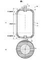
- FIG. 1 shows a high-pressure hydrogen tank 100.
- 1A is a cross-sectional view of the front view
- FIG. 1B is a bottom view.
- the high-pressure hydrogen tank 100 is for supplying hydrogen to a fuel cell for an automobile and is mounted on the automobile.
- the high-pressure hydrogen tank 100 includes a resin liner 10, a reinforcing layer 20, a valve side base 30, an end side base 40, a valve 50, a first protection member 61, and a second protection member 62.
- the resin liner 10 is for forming a space for filling hydrogen, and is produced by resin molding.
- the reinforcing layer 20 covers the outer periphery of the resin liner 10 in order to reinforce the resin liner 10.
- the material of the reinforcing layer 20 is CFRP (Carbon Fiber Reinforced Plastics).
- the reinforcing layer 20 is formed by an FW (Filament Winding) method.
- the resin liner 10 and the reinforcing layer 20 constitute a tank body.
- the tank body includes a body plate portion 80, a first end plate portion 91, and a second end plate portion 92.
- the body plate portion 80 is a part of the resin liner 10 and the reinforcing layer 20 and has a straight section. The direction of this straight line coincides with the direction of the axis O shown in FIG.
- the first end plate portion 91 and the second end plate portion 92 are parts of the resin liner 10 and the reinforcing layer 20 and are not the body plate portion 80. That is, the cross-sectional shape is a portion that is not a straight line along the major axis direction of the tank, and specifically a curved portion.
- the valve side cap 30 has a substantially cylindrical shape and includes a flange that protrudes from the outer peripheral surface.
- the valve-side base 30 is fixed by sandwiching the flange portion between the resin liner 10 and the reinforcing layer 20.
- the inner peripheral surface of the valve side cap 30 functions as a hydrogen entrance / exit.
- the valve 50 functions to open and close the hydrogen entrance / exit through the valve side cap 30.
- the valve 50 includes a fusing valve (not shown).
- the plug valve is a kind of safety valve, and has a function of releasing the pressure of stored gas to the outside when the high-pressure hydrogen tank 100 reaches a predetermined temperature or higher.
- a female screw is formed on the inner peripheral surface of the valve side cap 30, and a male screw is formed on the outer peripheral surface of the valve 50. By tightening this screw, the inside of the resin liner 10 is sealed.
- the end-side base 40 is disposed on the second end plate portion 92 so as to be exposed both inside and outside the tank. This arrangement is for radiating the heat inside the tank to the outside.
- a metal such as aluminum is used as the material of the end side cap 40.
- the first protective member 61 protects the thin-walled portion from impact by covering the thin-walled portion of the first end plate portion 91 and its periphery (hereinafter, the two are also referred to as “thin-walled portion”).
- the thin portion of the first end plate portion 91 is a portion where the thickness of the reinforcing layer 20 in the first end plate portion 91 is the thinnest, and is an intermediate portion in the first end plate portion 91.
- the intermediate part is a part away from both the valve side cap 30 and the body plate part 80.
- Such a thin-walled portion appears because the reinforcing layer 20 is formed using the FW method.
- the thin-walled part is weak against impact and high temperature as compared with other parts.
- the shape of the first protective member 61 is a shape obtained by removing the vicinity of the apex from the conical surface in order to cover the thin portion (hereinafter, this shape is referred to as “flat marker cone shape”). That is, polyurethane foam is used as the material of the first protective member 61 in order to improve impact resistance.
- the first protective member 61 is formed by molding and then fixed to the outer surface of the reinforcing layer 20 with an adhesive.
- the second protection member 62 protects the thin-walled portion from impact and high temperature by covering the thin-walled portion of the second end plate portion 92 and the like.
- the outer shape of the second protection member 62 is substantially the same as the outer shape of the first protection member 61.
- the second protective member 62 is fixed to the reinforcing layer 20 with an adhesive.
- the second protection member 62 has a two-layer internal structure. This internal structure is for exerting a protection function from both impact and high temperature.
- the second protection member 62 is produced by molding. This two-layer structure will be described with reference to FIGS.
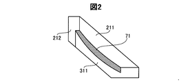
- FIGS. 2 and 3 show the left half of the end face of the mold and the second protective member 62 in order to explain the production process of the second protective member 62.
- the actual shape of the mold and the second protective member 62 is a shape obtained by rotating the shape shown in FIGS. 2 and 3 around the axis O.
- the two-layer structure of the second protective member 62 is composed of an inner layer 71 and an outer layer 72.
- FIG. 2 shows a first step of producing the inner layer 71 by molding. As shown in FIG. 2, a first upper mold 211, a second upper mold 212, and a first lower mold 311 are used in the first step.
- the material of the inner layer 71 is the same polyurethane foam as that of the first protective member 61.
- the inner layer 71 is formed by foaming by mixing two liquids using the above mold.
- FIG. 3 shows a second step of molding the outer layer 72.
- the first upper mold 211, the third upper mold 223, the fourth upper mold 224, and the second lower mold 322 are used in the second step.
- the mold used for the second process is prepared by replacing the parts other than the first upper mold 211 after the first process.
- the material of the outer layer 72 is a mixture of expanded graphite and foamed polyurethane.
- the outer layer 72 is formed by mixing and foaming a mixture of expanded graphite and a liquid used as a raw material for foamed polyurethane using the above mold. Since inner layer 71 and outer layer 72 both comprise polyurethane, they are chemically bonded to each other.
- the shape of the mold shown in FIGS. 2 and 3 is an example in which the mold can be divided vertically, and is not limited thereto.
- the second protective member 62 protects the thin portion of the second end plate portion 92 from impact and high temperature.
- the protection function from impact is exhibited by the inner layer 71 and the outer layer 72.
- the protection function from the high temperature is exhibited by the outer layer 72. Since the outer layer 72 contains expanded graphite, it expands rapidly due to thermal foaming when exposed to high temperatures. As a result, the high temperature flame and the like are kept away from the thin-walled portion, and a heat insulating effect is exhibited. This function makes it difficult for the thin-walled portion to reach a high temperature. As a result, the heat resistance performance of the high-pressure hydrogen tank 100 is improved.
- the second protective member 62 protects the thin-walled portion and the like, it only slightly increases the physique (mass and volume) of the high-pressure hydrogen tank 100. Moreover, since the outer diameter of the second protection member 62 is smaller than the outer diameter of the body plate portion 80 as shown in FIG. 1, the outer diameter of the high-pressure hydrogen tank 100 is not increased.
- the second protective member 62 does not slow the filling speed of the high-pressure hydrogen tank 100 too much. Since hydrogen is compressed at the time of filling, it becomes high temperature. Since it is not preferable that the temperature of the hydrogen is too high, it is preferable to fill the hydrogen so that the temperature does not reach a certain level. Therefore, if the heat radiation from the inside of the high-pressure hydrogen tank 100 to the outside is slow, the filling speed must be slowed down. Since the second protection member 62 covers only the thin wall portion or the like, the heat dissipation characteristics are not deteriorated as compared with the method in which the protection member covers the entire body plate portion 80. As a result, the filling speed is not so slow.
- the second protective member 62 has the effect of improving the heat resistance, it does not increase the size of the high-pressure hydrogen tank 100 and does not slow down the filling speed.
- Such a feature pays attention to the characteristics of the FW method in which the vicinity of the center of the first end plate portion 91 and the second end plate portion 92 is a thin portion, and the first protective member 61 and the second end portion are separated from each other. It implement
- the first protective member 61 is fixed to the first end plate portion 91 as described above.
- the first end plate portion 91 is provided with a valve 50 having a fusing valve. Since the first protective member 61 does not contain expanded graphite, it hardly expands even when exposed to high temperatures. As a result, the first protective member 61 does not hinder its operation due to expansion in a situation where the fusing valve should operate.
- the two-layer structure of the second protective member 62 has a strong bonding force between the layers. For this reason, it is hard to occur that the outer layer 72 falls off and the second protective member 62 loses the protection function from the high temperature. This effect is particularly significant when the outer layer 72 is expanded.
- This bonding force includes a chemical bonding force and a mechanical bonding force. The chemical bonding force is generated when the inner layer 71 and the outer layer 72 contain polyurethane.
- the mechanical coupling force is generated when the entire inner layer 71 functions as a tenon tenon and the recess of the outer layer 72 functions as a mortise hole.
- This function is provided by the shape of the inner layer 71 and the depressions of the outer layer 72, as shown in FIG.
- the shape of the inner layer 71 referred to here is a shape in which the portion as the inside of the second protective member 62 is wider than the portion exposed as the outer surface of the second protective member 62.
- the shape of the above-mentioned depression is a shape in which the inner layer 71 fits perfectly. A recess having a shape in which the inner layer 71 fits is inevitably produced by molding the outer layer 72 using the inner layer 71 as a part of a mold.
- the inner layer 71 and the outer layer 72 are not easily separated. Even if a force in the z direction is applied, the inner layer 71 and the outer layer 72 have a flat marker cone shape as described above, and thus do not act to separate the inner layer 71 and the outer layer 72.
- the method for realizing such mechanical coupling is simple because the inner layer 71 is molded as described above, and then the outer layer 72 is molded by using the inner layer 71 as a part of the mold. is there.
- the outer layer 72 can effectively protect the inner layer 71 from a high temperature because the depression functions as a mortise and encloses most of the inner layer 71 by the depression.
- the majority of the inner layer 71 referred to here is a portion that is not in contact with the reinforcing layer 20. Since polyurethane is easy to burn unless it has been subjected to flame retardant treatment, it is effective to protect the inner layer 71 from high temperatures.
- first protective member 61 and the second protective member 62 are fixed by an adhesive, they can be easily replaced and have excellent maintainability.
- the present invention is not limited to the above-described embodiments, examples, and modifications, and can be realized with various configurations without departing from the spirit thereof.
- the technical features in the embodiments, examples, and modifications corresponding to the technical features in each embodiment described in the summary section of the invention are to solve some or all of the above-described problems, or In order to achieve part or all of the above-described effects, replacement or combination can be performed as appropriate. If the technical feature is not described as essential in the present specification, it can be deleted as appropriate.
- Storing fluid may be other than hydrogen.
- Expanded graphite may be included in the inner layer of the second protective member, or expanded graphite may not be included in the outer layer.
- the second protective member may have a single layer structure, and the layer may contain expanded graphite.
Priority Applications (6)
| Application Number | Priority Date | Filing Date | Title |
|---|---|---|---|
| CA2883510A CA2883510C (en) | 2012-10-05 | 2013-09-26 | Pressure vessel and production method thereof |
| NO13844306A NO2905527T3 (ko) | 2012-10-05 | 2013-09-26 | |
| US14/433,377 US9464758B2 (en) | 2012-10-05 | 2013-09-26 | Pressure vessel and production method thereof |
| KR1020157008347A KR101682841B1 (ko) | 2012-10-05 | 2013-09-26 | 압력 용기 및 그 생산 방법 |
| EP13844306.4A EP2905527B1 (en) | 2012-10-05 | 2013-09-26 | Pressure vessel and production method therefor |
| CN201380050371.4A CN104662355B (zh) | 2012-10-05 | 2013-09-26 | 压力容器及其生产方法 |
Applications Claiming Priority (2)
| Application Number | Priority Date | Filing Date | Title |
|---|---|---|---|
| JP2012-223071 | 2012-10-05 | ||
| JP2012223071A JP5904081B2 (ja) | 2012-10-05 | 2012-10-05 | 圧力容器およびその生産方法 |
Publications (1)
| Publication Number | Publication Date |
|---|---|
| WO2014054251A1 true WO2014054251A1 (ja) | 2014-04-10 |
Family
ID=50434596
Family Applications (1)
| Application Number | Title | Priority Date | Filing Date |
|---|---|---|---|
| PCT/JP2013/005721 WO2014054251A1 (ja) | 2012-10-05 | 2013-09-26 | 圧力容器およびその生産方法 |
Country Status (8)
| Country | Link |
|---|---|
| US (1) | US9464758B2 (ko) |
| EP (1) | EP2905527B1 (ko) |
| JP (1) | JP5904081B2 (ko) |
| KR (1) | KR101682841B1 (ko) |
| CN (1) | CN104662355B (ko) |
| CA (1) | CA2883510C (ko) |
| NO (1) | NO2905527T3 (ko) |
| WO (1) | WO2014054251A1 (ko) |
Cited By (2)
| Publication number | Priority date | Publication date | Assignee | Title |
|---|---|---|---|---|
| JP2020117179A (ja) * | 2019-01-28 | 2020-08-06 | 本田技研工業株式会社 | 高圧タンク搭載車両 |
| JP7435149B2 (ja) | 2020-03-27 | 2024-02-21 | トヨタ自動車株式会社 | 高圧タンク |
Families Citing this family (17)
| Publication number | Priority date | Publication date | Assignee | Title |
|---|---|---|---|---|
| US11353160B2 (en) * | 2014-02-27 | 2022-06-07 | Hanwha Cimarron Llc | Pressure vessel |
| ITUA20161289A1 (it) * | 2016-02-19 | 2017-08-19 | Vicario Guido Francesco Edoardo | Bombola mobile intercambiabile in fibra di carbonio con valvola di sicurezza ad innesto istantaneo nel circuito di utilizzo su nuovi veicoli elettrici a doppia energia per il rifornimento veloce di grandi numeri giornalieri di auto, per ottenere larghe autonomie chilometriche, per ottenere la totale autonomia di rifornimento con bombole di scorta, con una rete di stazioni di servizio semplificate ad alto isolamento termico ignifugo e acustico, prive di fabbisogno di suolo pubblico per soste, per la produzione e lo storage in spazi ridotti di grandi quantita' di idrogeno elettrolitico prodotto con energie rinnovabili. per il loro impiego per l'automotive e per il risanamento ambientale attraverso l'uso di acqua elettrolitica in sostituzione del petrolio: si forma un sistema integrato globale di mobilita' elettrica a doppia energia con range extender ad idrogeno. |
| JP6614020B2 (ja) * | 2016-05-09 | 2019-12-04 | トヨタ自動車株式会社 | タンク |
| KR101944438B1 (ko) * | 2016-05-18 | 2019-02-01 | 일진복합소재 주식회사 | 내충격 부재를 구비한 압력 용기 |
| JP6601379B2 (ja) | 2016-12-06 | 2019-11-06 | トヨタ自動車株式会社 | 圧力容器および圧力容器の製造方法 |
| JP6601425B2 (ja) * | 2017-01-18 | 2019-11-06 | トヨタ自動車株式会社 | ガスタンク用のライナーおよびガスタンク |
| JP6597668B2 (ja) * | 2017-02-23 | 2019-10-30 | トヨタ自動車株式会社 | 圧力容器 |
| KR102043080B1 (ko) * | 2017-09-21 | 2019-11-12 | (주)동희산업 | 고압용기 및 그 제조방법 |
| JP7311243B2 (ja) * | 2017-12-28 | 2023-07-19 | トヨタ自動車株式会社 | プロテクタを有する高圧タンク |
| JP6695365B2 (ja) * | 2018-01-25 | 2020-05-20 | 本田技研工業株式会社 | 高圧タンク構造体 |
| DE102018206345A1 (de) * | 2018-04-25 | 2019-10-31 | Robert Bosch Gmbh | Schmelzsicherung, Gasbehälter und Verfahren zum Zusammenbauen einer Schmelzsicherung und zum Einbauen derselben in einen Gasbehälter |
| JP7165511B2 (ja) * | 2018-05-28 | 2022-11-04 | 株式会社イノアックコーポレーション | 保護部材 |
| KR102204702B1 (ko) * | 2018-11-06 | 2021-01-19 | 손승희 | 고압 용기 |
| JP7328766B2 (ja) * | 2019-02-13 | 2023-08-17 | 株式会社Fts | 圧力容器 |
| FR3129703A1 (fr) * | 2021-11-30 | 2023-06-02 | Faurecia Systemes D'echappement | Dispositif de protection pour réservoir de gaz sous pression |
| KR102632593B1 (ko) * | 2021-12-21 | 2024-02-05 | 주식회사 에테르씨티 | 아우터쉘을 구비한 압력용기 |
| CN115451324A (zh) * | 2022-09-14 | 2022-12-09 | 中材科技(苏州)有限公司 | 保护罩及高压储氢气瓶 |
Citations (6)
| Publication number | Priority date | Publication date | Assignee | Title |
|---|---|---|---|---|
| JPH0471628U (ko) * | 1990-11-01 | 1992-06-24 | ||
| JPH1194198A (ja) * | 1997-09-24 | 1999-04-09 | Ihi Plantec:Kk | 竪型断熱低温タンク |
| JP2001524653A (ja) * | 1997-11-14 | 2001-12-04 | マンネスマン・アクチエンゲゼルシャフト | プラスチック製ライナーを有する、気体媒体を加圧下に貯蔵するためのコンポジット圧力容器 |
| JP2004176798A (ja) * | 2002-11-26 | 2004-06-24 | Masateru Irie | 液化ガス容器 |
| JP2011194952A (ja) * | 2010-03-18 | 2011-10-06 | Honda Motor Co Ltd | タンク構造体 |
| JP2012002257A (ja) | 2010-06-15 | 2012-01-05 | Honda Motor Co Ltd | 圧力容器 |
Family Cites Families (14)
| Publication number | Priority date | Publication date | Assignee | Title |
|---|---|---|---|---|
| US3317074A (en) * | 1963-06-17 | 1967-05-02 | Douglas Aircraft Co Inc | Cryogenic containers |
| US3883625A (en) * | 1970-02-12 | 1975-05-13 | Dow Chemical Co | Method for making expandable plastics |
| US4122203A (en) * | 1978-01-09 | 1978-10-24 | Stahl Joel S | Fire protective thermal barriers for foam plastics |
| FR2647183B1 (fr) | 1989-05-18 | 1991-07-26 | Hembert Claude | Dispositif pour proteger les extremites de reservoir de fluide en materiaux composites |
| US5476189A (en) | 1993-12-03 | 1995-12-19 | Duvall; Paul F. | Pressure vessel with damage mitigating system |
| JP3025569U (ja) | 1995-06-14 | 1996-06-21 | 株式会社サン・フロンティア・テクノロジー | 高圧ガス容器の保護装置 |
| JP2001021099A (ja) * | 1999-07-06 | 2001-01-26 | Toyota Autom Loom Works Ltd | 圧力容器 |
| JP2002188794A (ja) | 2000-12-21 | 2002-07-05 | Honda Motor Co Ltd | 高圧水素タンクおよび高圧水素タンクの製造方法 |
| BRPI0510010B1 (pt) * | 2004-04-23 | 2018-07-31 | Amtrol Licensing Inc. | Vaso de pressão com camisa de proteção |
| JP4935117B2 (ja) * | 2005-11-08 | 2012-05-23 | トヨタ自動車株式会社 | タンク |
| JP2007333175A (ja) * | 2006-06-19 | 2007-12-27 | Toyota Motor Corp | 圧力容器 |
| US8038029B2 (en) * | 2008-06-13 | 2011-10-18 | GM Global Technology Operations LLC | Activation of a pressure relief device |
| JP2010184974A (ja) * | 2009-02-10 | 2010-08-26 | Alpha Kaken Kk | 耐火断熱被覆材 |
| JP5027894B2 (ja) | 2010-01-25 | 2012-09-19 | 本田技研工業株式会社 | ガスタンク |
-
2012
- 2012-10-05 JP JP2012223071A patent/JP5904081B2/ja active Active
-
2013
- 2013-09-26 CN CN201380050371.4A patent/CN104662355B/zh active Active
- 2013-09-26 US US14/433,377 patent/US9464758B2/en active Active
- 2013-09-26 CA CA2883510A patent/CA2883510C/en active Active
- 2013-09-26 WO PCT/JP2013/005721 patent/WO2014054251A1/ja active Application Filing
- 2013-09-26 NO NO13844306A patent/NO2905527T3/no unknown
- 2013-09-26 EP EP13844306.4A patent/EP2905527B1/en active Active
- 2013-09-26 KR KR1020157008347A patent/KR101682841B1/ko active IP Right Grant
Patent Citations (6)
| Publication number | Priority date | Publication date | Assignee | Title |
|---|---|---|---|---|
| JPH0471628U (ko) * | 1990-11-01 | 1992-06-24 | ||
| JPH1194198A (ja) * | 1997-09-24 | 1999-04-09 | Ihi Plantec:Kk | 竪型断熱低温タンク |
| JP2001524653A (ja) * | 1997-11-14 | 2001-12-04 | マンネスマン・アクチエンゲゼルシャフト | プラスチック製ライナーを有する、気体媒体を加圧下に貯蔵するためのコンポジット圧力容器 |
| JP2004176798A (ja) * | 2002-11-26 | 2004-06-24 | Masateru Irie | 液化ガス容器 |
| JP2011194952A (ja) * | 2010-03-18 | 2011-10-06 | Honda Motor Co Ltd | タンク構造体 |
| JP2012002257A (ja) | 2010-06-15 | 2012-01-05 | Honda Motor Co Ltd | 圧力容器 |
Non-Patent Citations (1)
| Title |
|---|
| See also references of EP2905527A4 |
Cited By (3)
| Publication number | Priority date | Publication date | Assignee | Title |
|---|---|---|---|---|
| JP2020117179A (ja) * | 2019-01-28 | 2020-08-06 | 本田技研工業株式会社 | 高圧タンク搭載車両 |
| US11292336B2 (en) | 2019-01-28 | 2022-04-05 | Honda Motor Co., Ltd. | Vehicle equipped with high pressure tank |
| JP7435149B2 (ja) | 2020-03-27 | 2024-02-21 | トヨタ自動車株式会社 | 高圧タンク |
Also Published As
| Publication number | Publication date |
|---|---|
| CA2883510C (en) | 2017-01-24 |
| NO2905527T3 (ko) | 2018-03-24 |
| US9464758B2 (en) | 2016-10-11 |
| EP2905527A1 (en) | 2015-08-12 |
| CN104662355B (zh) | 2017-05-03 |
| CN104662355A (zh) | 2015-05-27 |
| JP5904081B2 (ja) | 2016-04-13 |
| EP2905527A4 (en) | 2015-08-12 |
| CA2883510A1 (en) | 2014-04-10 |
| KR101682841B1 (ko) | 2016-12-05 |
| EP2905527B1 (en) | 2017-10-25 |
| JP2014074470A (ja) | 2014-04-24 |
| US20150204483A1 (en) | 2015-07-23 |
| KR20150051231A (ko) | 2015-05-11 |
Similar Documents
| Publication | Publication Date | Title |
|---|---|---|
| JP5904081B2 (ja) | 圧力容器およびその生産方法 | |
| KR102043080B1 (ko) | 고압용기 및 그 제조방법 | |
| JP6256190B2 (ja) | 高圧ガスタンクの製造方法 | |
| JP2007056972A (ja) | 真空断熱材及びそれを用いた冷蔵庫 | |
| JP7384229B2 (ja) | プロテクタを有する高圧タンク | |
| JP2017145936A (ja) | 高圧ガスタンク | |
| KR101944438B1 (ko) | 내충격 부재를 구비한 압력 용기 | |
| JP2018150950A (ja) | 高圧タンク | |
| US8657146B2 (en) | Optimized high pressure vessel | |
| KR20120136319A (ko) | 액화천연가스 저장탱크의 펌프타워 베이스서포트 구조체 | |
| JP2017172724A (ja) | 断熱パネルおよび断熱構造 | |
| JP6781581B2 (ja) | 車両の非シリンダ型複合材圧力容器 | |
| WO2015186346A1 (ja) | 断熱体および断熱容器 | |
| KR20200052000A (ko) | 고압 용기 | |
| KR102052631B1 (ko) | 진공단열 패널 | |
| KR102204697B1 (ko) | 고압 용기 | |
| KR101476615B1 (ko) | 가스 탱크 | |
| JP2017198319A (ja) | 高圧タンク | |
| KR102248953B1 (ko) | 가스 컨테이너 | |
| KR20210047541A (ko) | 액화가스 저장탱크의 진공단열시스템 | |
| KR101358305B1 (ko) | 액화가스 화물창 단열 구조체 시공 방법 | |
| JP4877896B2 (ja) | 樹脂製燃料容器 | |
| KR20220068012A (ko) | 압력 용기 | |
| JP2024511618A (ja) | エンドボスの密封 | |
| JP2018100689A (ja) | 断熱部材およびその製造方法 |
Legal Events
| Date | Code | Title | Description |
|---|---|---|---|
| 121 | Ep: the epo has been informed by wipo that ep was designated in this application |
Ref document number: 13844306 Country of ref document: EP Kind code of ref document: A1 |
|
| REEP | Request for entry into the european phase |
Ref document number: 2013844306 Country of ref document: EP |
|
| WWE | Wipo information: entry into national phase |
Ref document number: 2013844306 Country of ref document: EP |
|
| ENP | Entry into the national phase |
Ref document number: 2883510 Country of ref document: CA |
|
| ENP | Entry into the national phase |
Ref document number: 20157008347 Country of ref document: KR Kind code of ref document: A |
|
| WWE | Wipo information: entry into national phase |
Ref document number: 14433377 Country of ref document: US |
|
| NENP | Non-entry into the national phase |
Ref country code: DE |