WO2014050583A1 - 赤外線カットフィルム、赤外線カット合わせガラスおよび赤外線カット部材 - Google Patents
赤外線カットフィルム、赤外線カット合わせガラスおよび赤外線カット部材 Download PDFInfo
- Publication number
- WO2014050583A1 WO2014050583A1 PCT/JP2013/074631 JP2013074631W WO2014050583A1 WO 2014050583 A1 WO2014050583 A1 WO 2014050583A1 JP 2013074631 W JP2013074631 W JP 2013074631W WO 2014050583 A1 WO2014050583 A1 WO 2014050583A1
- Authority
- WO
- WIPO (PCT)
- Prior art keywords
- infrared
- group
- layer
- infrared cut
- carbon atoms
- Prior art date
- Legal status (The legal status is an assumption and is not a legal conclusion. Google has not performed a legal analysis and makes no representation as to the accuracy of the status listed.)
- Ceased
Links
- 0 CCCCC*(C)OC(CCc(c(N1S(c2ccccc2)(N2CC2)N2C(C=CC(C3)C(C)(C)*=C)=C3C=CC22)c34)*c(C(CC5)=NC(CC6)=C5C=C6C(C)(C)C)*3[n](*(c3ccccc3)c3ccccc3)c([C@@](CC=C3)C=*3OC*(CC)CCCC)c4C1=C2C#N)=CC Chemical compound CCCCC*(C)OC(CCc(c(N1S(c2ccccc2)(N2CC2)N2C(C=CC(C3)C(C)(C)*=C)=C3C=CC22)c34)*c(C(CC5)=NC(CC6)=C5C=C6C(C)(C)C)*3[n](*(c3ccccc3)c3ccccc3)c([C@@](CC=C3)C=*3OC*(CC)CCCC)c4C1=C2C#N)=CC 0.000 description 2
Images


Classifications
-
- G—PHYSICS
- G02—OPTICS
- G02B—OPTICAL ELEMENTS, SYSTEMS OR APPARATUS
- G02B5/00—Optical elements other than lenses
- G02B5/20—Filters
- G02B5/28—Interference filters
- G02B5/281—Interference filters designed for the infrared light
- G02B5/282—Interference filters designed for the infrared light reflecting for infrared and transparent for visible light, e.g. heat reflectors, laser protection
-
- C—CHEMISTRY; METALLURGY
- C07—ORGANIC CHEMISTRY
- C07D—HETEROCYCLIC COMPOUNDS
- C07D487/00—Heterocyclic compounds containing nitrogen atoms as the only ring hetero atoms in the condensed system, not provided for by groups C07D451/00 - C07D477/00
- C07D487/02—Heterocyclic compounds containing nitrogen atoms as the only ring hetero atoms in the condensed system, not provided for by groups C07D451/00 - C07D477/00 in which the condensed system contains two hetero rings
- C07D487/04—Ortho-condensed systems
-
- C—CHEMISTRY; METALLURGY
- C07—ORGANIC CHEMISTRY
- C07D—HETEROCYCLIC COMPOUNDS
- C07D487/00—Heterocyclic compounds containing nitrogen atoms as the only ring hetero atoms in the condensed system, not provided for by groups C07D451/00 - C07D477/00
- C07D487/22—Heterocyclic compounds containing nitrogen atoms as the only ring hetero atoms in the condensed system, not provided for by groups C07D451/00 - C07D477/00 in which the condensed system contains four or more hetero rings
-
- G—PHYSICS
- G02—OPTICS
- G02B—OPTICAL ELEMENTS, SYSTEMS OR APPARATUS
- G02B1/00—Optical elements characterised by the material of which they are made; Optical coatings for optical elements
- G02B1/04—Optical elements characterised by the material of which they are made; Optical coatings for optical elements made of organic materials, e.g. plastics
-
- G—PHYSICS
- G02—OPTICS
- G02B—OPTICAL ELEMENTS, SYSTEMS OR APPARATUS
- G02B5/00—Optical elements other than lenses
- G02B5/20—Filters
- G02B5/206—Filters comprising particles embedded in a solid matrix
-
- G—PHYSICS
- G02—OPTICS
- G02B—OPTICAL ELEMENTS, SYSTEMS OR APPARATUS
- G02B5/00—Optical elements other than lenses
- G02B5/20—Filters
- G02B5/208—Filters for use with infrared or ultraviolet radiation, e.g. for separating visible light from infrared and/or ultraviolet radiation
-
- G—PHYSICS
- G02—OPTICS
- G02B—OPTICAL ELEMENTS, SYSTEMS OR APPARATUS
- G02B5/00—Optical elements other than lenses
- G02B5/20—Filters
- G02B5/22—Absorbing filters
- G02B5/223—Absorbing filters containing organic substances, e.g. dyes, inks or pigments
-
- G—PHYSICS
- G02—OPTICS
- G02B—OPTICAL ELEMENTS, SYSTEMS OR APPARATUS
- G02B5/00—Optical elements other than lenses
- G02B5/20—Filters
- G02B5/26—Reflecting filters
-
- G—PHYSICS
- G02—OPTICS
- G02F—OPTICAL DEVICES OR ARRANGEMENTS FOR THE CONTROL OF LIGHT BY MODIFICATION OF THE OPTICAL PROPERTIES OF THE MEDIA OF THE ELEMENTS INVOLVED THEREIN; NON-LINEAR OPTICS; FREQUENCY-CHANGING OF LIGHT; OPTICAL LOGIC ELEMENTS; OPTICAL ANALOGUE/DIGITAL CONVERTERS
- G02F1/00—Devices or arrangements for the control of the intensity, colour, phase, polarisation or direction of light arriving from an independent light source, e.g. switching, gating or modulating; Non-linear optics
- G02F1/01—Devices or arrangements for the control of the intensity, colour, phase, polarisation or direction of light arriving from an independent light source, e.g. switching, gating or modulating; Non-linear optics for the control of the intensity, phase, polarisation or colour
- G02F1/13—Devices or arrangements for the control of the intensity, colour, phase, polarisation or direction of light arriving from an independent light source, e.g. switching, gating or modulating; Non-linear optics for the control of the intensity, phase, polarisation or colour based on liquid crystals, e.g. single liquid crystal display cells
- G02F1/133—Constructional arrangements; Operation of liquid crystal cells; Circuit arrangements
- G02F1/1333—Constructional arrangements; Manufacturing methods
- G02F1/133365—Cells in which the active layer comprises a liquid crystalline polymer
-
- Y—GENERAL TAGGING OF NEW TECHNOLOGICAL DEVELOPMENTS; GENERAL TAGGING OF CROSS-SECTIONAL TECHNOLOGIES SPANNING OVER SEVERAL SECTIONS OF THE IPC; TECHNICAL SUBJECTS COVERED BY FORMER USPC CROSS-REFERENCE ART COLLECTIONS [XRACs] AND DIGESTS
- Y10—TECHNICAL SUBJECTS COVERED BY FORMER USPC
- Y10T—TECHNICAL SUBJECTS COVERED BY FORMER US CLASSIFICATION
- Y10T428/00—Stock material or miscellaneous articles
- Y10T428/25—Web or sheet containing structurally defined element or component and including a second component containing structurally defined particles
-
- Y—GENERAL TAGGING OF NEW TECHNOLOGICAL DEVELOPMENTS; GENERAL TAGGING OF CROSS-SECTIONAL TECHNOLOGIES SPANNING OVER SEVERAL SECTIONS OF THE IPC; TECHNICAL SUBJECTS COVERED BY FORMER USPC CROSS-REFERENCE ART COLLECTIONS [XRACs] AND DIGESTS
- Y10—TECHNICAL SUBJECTS COVERED BY FORMER USPC
- Y10T—TECHNICAL SUBJECTS COVERED BY FORMER US CLASSIFICATION
- Y10T428/00—Stock material or miscellaneous articles
- Y10T428/31504—Composite [nonstructural laminate]
- Y10T428/31551—Of polyamidoester [polyurethane, polyisocyanate, polycarbamate, etc.]
- Y10T428/31616—Next to polyester [e.g., alkyd]
-
- Y—GENERAL TAGGING OF NEW TECHNOLOGICAL DEVELOPMENTS; GENERAL TAGGING OF CROSS-SECTIONAL TECHNOLOGIES SPANNING OVER SEVERAL SECTIONS OF THE IPC; TECHNICAL SUBJECTS COVERED BY FORMER USPC CROSS-REFERENCE ART COLLECTIONS [XRACs] AND DIGESTS
- Y10—TECHNICAL SUBJECTS COVERED BY FORMER USPC
- Y10T—TECHNICAL SUBJECTS COVERED BY FORMER US CLASSIFICATION
- Y10T428/00—Stock material or miscellaneous articles
- Y10T428/31504—Composite [nonstructural laminate]
- Y10T428/31786—Of polyester [e.g., alkyd, etc.]
- Y10T428/31797—Next to addition polymer from unsaturated monomers
Definitions
- the present invention relates to an infrared cut film, an infrared cut laminated glass, and an infrared cut member.
- heat ray shielding materials for automobiles and building windows have been developed as an energy-saving measure for reducing carbon dioxide. From the viewpoint of heat ray shielding (heat shielding performance), a heat ray reflection type without re-radiation is preferable to a heat ray absorption type with re-radiation of absorbed light into the room (about 1/3 of the absorbed solar radiation energy).
- heat shielding performance a heat ray reflection type without re-radiation is preferable to a heat ray absorption type with re-radiation of absorbed light into the room (about 1/3 of the absorbed solar radiation energy).
- Various proposals have been made.
- heat ray shielding materials for automobiles and building windows are required to have high visible light transmittance (invisibility) from the viewpoint of safety and the like, and are used over a long period of time. Fastness (light resistance) is also required.
- Patent Document 1 discloses a heat ray shielding material having a cholesteric liquid crystal layer, wherein a selective reflection wavelength of the cholesteric liquid crystal layer is in an infrared light region, so that the heat ray shielding material has high heat shielding performance. It is described that a shielding material can be provided.
- Patent Document 2 discloses a near-infrared absorbing material in which a near-infrared absorbing layer and a cholesteric liquid crystal layer are laminated on a substrate, and the near-infrared absorbing layer includes a resin and an inorganic near-infrared ray having an average particle diameter of 40 to 200 nm.
- Reflective color tone is improved by a visible light transmissive near-infrared absorbing material containing an absorbent and a cholesteric liquid crystal layer containing a cholesteric liquid crystal material having a fixed cholesteric structure and a selective reflection wavelength in the red light region. Describes that it can provide a near-infrared absorbing material that does not exhibit blue color, effectively absorbs near-infrared rays, has high visible light transmittance, and is excellent in transparency.
- the absorption or reflection by the metal fine particles described in Patent Document 2 cannot be said to be sufficient for absorption or reflection in the wavelength region of 750 nm to 920 nm where the energy is high even in sunlight.
- Patent Documents 1 and 2 have no description about using a near-infrared absorbing dye, but examples of forming a near-infrared absorbing layer using a near-infrared absorbing dye are known.
- Patent Documents 3 and 4 disclose examples using pyrrolopyrrole dyes as near-infrared absorbing compounds.
- Patent Documents 3 and 4 did not disclose or suggest combining a near-infrared absorbing layer and a near-infrared reflecting layer.
- Patent Document 5 discloses an example in which a near-infrared absorbing layer using several types of organic dyes that absorb near-infrared rays near 800 nm and a near-infrared reflecting layer made of cholesteric liquid crystal are used together. It is described that the amount of mixed pigment can be reduced by using an infrared cut filter for use.
- the phthalocyanine dye has a low visible light transmittance, the cyanine dye has a low light resistance, and the nickel complex dye has a concern about environmental harm. Neither was satisfactory.
- an infrared cut film having both excellent invisibility and fastness and high heat shielding performance has not been known so far.
- the problem to be solved by the present invention is to provide an infrared cut film which is excellent in both invisibility and fastness and has high heat shielding performance.
- the inventors fixed a cholesteric liquid crystal phase with a near-infrared absorbing layer having a maximum absorption wavelength in a specific range and containing a near-infrared absorbing compound having a specific structure.
- the present inventors have found that an infrared cut film having excellent invisibility and fastness and high heat shielding performance can be obtained by using a combined near-infrared reflective layer.
- the present invention which is a specific means for solving the above problems, is as follows.
- a transparent base material a near-infrared absorbing layer containing a near-infrared absorbing agent having a maximum absorption wavelength of 750 nm to 920 nm, and at least one near-infrared reflecting layer formed by fixing a cholesteric liquid crystal phase,
- the infrared cut film, wherein the near infrared absorber is a compound represented by the following general formula (1).
- R 1a and R 1b may be the same or different from each other, and each independently represents an alkyl group, an aryl group, or a heteroaryl group.
- R 2 and R 3 are each independently Represents a hydrogen atom or a substituent, and at least one of R 2 and R 3 is an electron-withdrawing group, and R 2 and R 3 may be bonded to each other to form a ring, and R 4 represents a hydrogen atom or an alkyl A group, an aryl group, a heteroaryl group, a substituted boron or a metal atom, and R 4 may be covalently or coordinately bonded to at least one of R 1a , R 1b and R 3.
- the near-infrared absorber preferably has an absorbance at 550 nm of 0.1 or less when the absorbance at the maximum absorption wavelength is 1.
- the near infrared absorber is preferably in a dispersed state of fine particles of the compound represented by the general formula (1).
- the number average particle diameter of the fine particles of the compound represented by the general formula (1) is preferably 5 to 500 nm.
- fine particles of the compound represented by the general formula (1) are dispersed in an ultraviolet curable resin or a thermoplastic resin.
- the near infrared absorption layer is preferably formed by coating.
- at least one of the near-infrared reflective layers has a maximum reflectance value of 750 nm to 1100 nm of 40% or more. Is preferred.
- the near-infrared reflective layer is fixed by photopolymerization after applying and aligning a cholesteric liquid crystal composed of a polymerizable liquid crystal. It is preferable to be formed.
- the near-infrared reflective layer reflects circularly polarized light in opposite directions, and a reflection wavelength range is 750 to 900 nm.
- a reflective layer in which two cholesteric liquid crystal phases having the same central reflection wavelength are fixed.
- the infrared cut film according to any one of [1] to [9] preferably further contains at least one of a metal fine particle dispersion and a diimmonium dye.
- the metal fine particle dispersion is preferably a composite tungsten oxide represented by the following general formula (I).
- the infrared cut film according to any one of [1] to [11] further includes at least one of an easy-adhesion layer, a hard coat layer, an ultraviolet absorption layer, an adhesive layer, and a surface protective layer. Is preferred.
- An infrared cut laminated glass comprising two glass plates and the infrared cut film according to any one of [1] to [12] sandwiched therebetween.
- An infrared cut member comprising the infrared cut film according to any one of [1] to [12], which is used for bonding to a building and a vehicle window.
- an infrared cut film that is excellent in both invisibility and fastness and has high heat shielding performance.
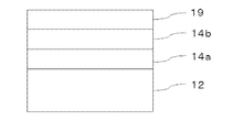
- FIG. 1 is a schematic view showing an example of an infrared cut film of the present invention.
- FIG. 2 is a schematic view showing another example of the infrared cut film of the present invention.
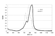
- FIG. 3 is a graph showing a spectrum in which the absorbance at the maximum absorption wavelength of the dye dispersions A-1 and A-2 is normalized to 1.
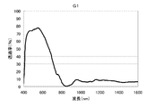
- FIG. 4 is a graph showing the transmission spectrum of the infrared cut laminated glass G1 of Example 5.
- FIG. 5 is a graph showing the transmission spectrum of the infrared cut laminated glass G2 of Example 6.
- a numerical range represented by using “to” means a range including numerical values described before and after “to” as a lower limit value and an upper limit value.
- the infrared cut film of the present invention comprises a transparent substrate, a near infrared absorbing layer containing a near infrared absorber having a maximum absorption wavelength of 750 nm to 920 nm, and at least one near infrared reflecting layer formed by fixing a cholesteric liquid crystal phase.
- the near-infrared absorber is a compound represented by the following general formula (1).
- R 1a and R 1b may be the same or different from each other, and each independently represents an alkyl group, an aryl group, or a heteroaryl group.
- R 2 and R 3 are each independently Represents a hydrogen atom or a substituent, and at least one of R 2 and R 3 is an electron-withdrawing group, and R 2 and R 3 may be bonded to each other to form a ring, and R 4 represents a hydrogen atom or an alkyl A group, an aryl group, a heteroaryl group, a substituted boron or a metal atom, and R 4 may be covalently or coordinately bonded to at least one of R 1a , R 1b and R 3. )
- the infrared cut film of the present invention is excellent in both invisibility and fastness, and has high heat shielding performance.
- a more preferable embodiment of the infrared cut film of the present invention will be specifically described.
- the visible light transmittance of the infrared cut film of the present invention is preferably 60% or more, more preferably 65% or more, and particularly preferably 70% or more.
- the visible light transmittance is 70% or more, for example, when used as glass for automobiles or glass for buildings, the outside is easy to see.
- FIG. 1 is a schematic view showing an example of an infrared cut film of the present invention, in which near-infrared reflective layers 14 a and 14 b formed by fixing two cholesteric liquid crystal layers are laminated on a transparent substrate 12.
- a near infrared absorbing layer 19 containing a near infrared absorbing agent is laminated thereon.
- FIG. 2 is a schematic view showing another example of the infrared cut film of the present invention.
- Near infrared reflection layers 14a and 14b formed by fixing two cholesteric liquid crystal layers on a transparent substrate 12 are laminated.
- a near-infrared absorbing layer 19 containing a near-infrared absorber is laminated thereon, and another infrared absorbing layer 20 containing a metal fine particle dispersion or a diimmonium dye is further laminated thereon.
- the other infrared absorption layer 20 containing the metal fine particle dispersion or the diimmonium dye may be an infrared absorption layer having only an infrared absorption function or a layer also serving as another functional layer.
- the layer that also serves as another functional layer include an easy-adhesion layer for a laminated glass interlayer mixed with a diimmonium dye.
- the infrared cut film of the present invention has a transparent substrate.
- limiting in particular as said support body A well-known transparent base material can be used.
- the transparent substrate is not particularly limited as long as it is an optically transparent transparent substrate, and can be appropriately selected according to the purpose. For example, the material having a visible light transmittance of 70% or more, preferably 80 % Or higher, and those having a high transmittance in the near infrared region.
- the transparent substrate is not particularly limited in its shape, structure, size, material, and the like, and can be appropriately selected according to the purpose.
- the shape examples include a flat plate shape, and the structure may be a single layer structure or a laminated structure, and the size may be the size of the infrared cut film. It can be appropriately selected according to the above.
- the material for the transparent substrate is not particularly limited and may be appropriately selected depending on the intended purpose.
- polyolefin resins such as polyethylene, polypropylene, poly-4-methylpentene-1, polybutene-1, and the like; polyethylene terephthalate Polyester resins such as polyethylene naphthalate; polycarbonate resins, polyvinyl chloride resins, polyphenylene sulfide resins, polyether sulfone resins, polyethylene sulfide resins, polyphenylene ether resins, styrene resins, acrylic resins, Examples thereof include films made of a polyamide-based resin, a polyimide-based resin, a cellulose-based resin such as cellulose acetate, or a laminated film thereof.
- the thickness of the transparent substrate is not particularly limited and can be appropriately selected according to the purpose of use of the infrared cut film. Usually, it is about 10 ⁇ m to 500 ⁇ m, but it is thinner from the viewpoint of thinning demand. Is preferred.
- the thickness of the transparent substrate is preferably 10 ⁇ m to 100 ⁇ m, more preferably 20 to 75 ⁇ m, and particularly preferably 35 to 75 ⁇ m. When the thickness of the support is sufficiently thick, adhesion failure tends to hardly occur.
- the thickness of the said transparent base material is thin enough, when sticking to a building material or a motor vehicle as an infrared cut film, it is not too strong as a material and it exists in the tendency which becomes easy to construct. Furthermore, since the transparent substrate is sufficiently thin, the visible light transmittance increases, and the raw material cost tends to be suppressed.
- the infrared cut film of the present invention has a near infrared absorption layer containing a near infrared absorber having a maximum absorption wavelength of 750 nm to 920 nm, and the near infrared absorber is a compound represented by the following general formula (1). It is characterized by being.
- R 1a and R 1b may be the same or different from each other, and each independently represents an alkyl group, an aryl group, or a heteroaryl group.
- R 2 and R 3 are each independently Represents a hydrogen atom or a substituent, and at least one of R 2 and R 3 is an electron-withdrawing group, and R 2 and R 3 may be bonded to each other to form a ring, and R 4 represents a hydrogen atom or an alkyl A group, an aryl group, a heteroaryl group, a substituted boron or a metal atom, and R 4 may be covalently or coordinately bonded to at least one of R 1a , R 1b and R 3. )
- the near infrared absorbing layer uses a near infrared absorbing agent having a maximum absorption wavelength of 750 nm to 920 nm.
- the maximum absorption wavelength of the near infrared absorber is preferably 770 nm to 900 nm, and more preferably 780 nm to 900 nm.
- the absorbance at the maximum absorption wavelength of the near infrared absorber is 1, the absorbance at 550 nm is 0.1 or less, which improves the invisibility and increases the visible light transmittance of the near infrared absorption layer. From the viewpoint of
- the alkyl group represented by R 1a or R 1b is preferably an alkyl group having 1 to 30 carbon atoms, more preferably 1 to 20 carbon atoms, and particularly preferably 1 to 10 carbon atoms. is there.
- methyl, ethyl, iso-propyl, tert-butyl, n-octyl, n-decyl, n-hexadecyl, 2-methylbutyl, 2-ethylcyclohexyl, cyclopentyl, cyclohexyl and the like can be mentioned.
- the aryl group represented by R 1a and R 1b is preferably an aryl group having 6 to 30 carbon atoms, more preferably 6 to 20 carbon atoms, and particularly preferably 6 to 12 carbon atoms.
- the heteroaryl group represented by R 1a and R 1b is preferably a heteroaryl group having 1 to 30 carbon atoms, more preferably 1 to 12 carbon atoms.
- the hetero atom include a nitrogen atom, an oxygen atom, and a sulfur atom.
- Specific examples of the heteroaryl group include imidazolyl, pyridyl, quinolyl, furyl, thienyl, benzoxazolyl, benzimidazolyl, benzthiazolyl, naphthothiazolyl, benzoxazolyl, m-carbazolyl, azepinyl and the like.
- the group represented by R 1a and R 1b is preferably an aryl group, more preferably o-methylphenyl or 4-alkoxyphenyl, and particularly preferably 4-alkoxyphenyl.
- the number of carbon atoms of the alkoxy group in the 4-alkoxyphenyl group is preferably 1 to 10, more preferably 1 to 8, which enhances dispersibility and facilitates association, shifting the absorption to the longer wavelength side. From the viewpoint of making it, 1 to 6 is particularly preferable, and 4- (2-methylbutyloxy) phenyl is more particularly preferable.
- the alkoxy group in the 4-alkoxyphenyl group is preferably a branched alkoxy group.
- R 1a and R 1b in the general formula (1) may be the same as or different from each other.
- R 2 and R 3 each independently represent a hydrogen atom or a substituent T, at least one of which is an electron-withdrawing group, and R 2 and R 3 may be bonded to form a ring.
- substituent T include the following. These substituents may be further substituted.
- An alkyl group (preferably having 1 to 30 carbon atoms, more preferably 1 to 20 carbon atoms, particularly preferably 1 to 10 carbon atoms, such as methyl, ethyl, iso-propyl, tert-butyl, n-octyl, n -Decyl, n-hexadecyl, 2-methylbutyl, 2-ethylcyclohexyl, cyclopentyl, cyclohexyl, etc.)
- An alkenyl group (preferably having 2 to 30 carbon atoms, more preferably 2 to 20 carbon atoms, particularly preferably 2 to 10 carbon atoms, such as vinyl, allyl, 2-butenyl, 3-pentenyl, etc.)
- An alkynyl group (preferably having 2 to 30 carbon atoms, more preferably 2 to 20 carbon atoms, particularly preferably 2 to 10 carbon atoms, and examples thereof include propargyl and 3-pentynyl.
- An aryl group (preferably having 6 to 30 carbon atoms, more preferably 6 to 20 carbon atoms, particularly preferably 6 to 12 carbon atoms, such as phenyl, p-methylphenyl, biphenyl, naphthyl, anthranyl, phenanthryl, etc.) )
- An amino group (preferably having 0 to 30 carbon atoms, more preferably 0 to 20 carbon atoms, particularly preferably 0 to 10 carbon atoms, including an alkylamino group, an arylamino group, and a heterocyclic amino group, such as amino, And methylamino, dimethylamino, diethylamino, dibenzylamino, diphenylamino, ditolylamino and the like.
- An alkoxy group (preferably having 1 to 30 carbon atoms, more preferably 1 to 20 carbon atoms, particularly preferably 1 to 10 carbon atoms, such as methoxy, ethoxy, butoxy, 2-ethylhexyloxy, etc.)
- An aryloxy group (preferably having 6 to 30 carbon atoms, more preferably 6 to 20 carbon atoms, particularly preferably 6 to 12 carbon atoms, and examples thereof include phenyloxy, 1-naphthyloxy, 2-naphthyloxy and the like.
- An aromatic heterocyclic oxy group (preferably having 1 to 30 carbon atoms, more preferably 1 to 20 carbon atoms, particularly preferably 1 to 12 carbon atoms, and examples thereof include pyridyloxy, pyrazyloxy, pyrimidyloxy, quinolyloxy and the like. )
- Acyl group (preferably having 1 to 30 carbon atoms, more preferably 1 to 20 carbon atoms, particularly preferably 1 to 12 carbon atoms, and examples thereof include acetyl, benzoyl, formyl, pivaloyl, etc.)
- An alkoxycarbonyl group (preferably having 2 to 30 carbon atoms, more preferably 2 to 20 carbon atoms, particularly preferably 2 to 12 carbon atoms, and examples thereof include methoxycarbonyl and ethoxycarbonyl).
- Aryloxycarbonyl group (preferably having 7 to 30 carbon atoms, more preferably 7 to 20 carbon atoms, particularly preferably 7 to 12 carbon atoms, and examples thereof include phenyloxycarbonyl).
- Acyloxy group (preferably having 2 to 30 carbon atoms, more preferably 2 to 20 carbon atoms, particularly preferably 2 to 10 carbon atoms, and examples thereof include acetoxy and benzoyloxy).
- Acylamino group (preferably having 2 to 30 carbon atoms, more preferably 2 to 20 carbon atoms, particularly preferably 2 to 10 carbon atoms, and examples thereof include acetylamino and benzoylamino)
- An alkoxycarbonylamino group (preferably having 2 to 30 carbon atoms, more preferably 2 to 20 carbon atoms, particularly preferably 2 to 12 carbon atoms, and examples thereof include methoxycarbonylamino).
- An aryloxycarbonylamino group (preferably having 7 to 30 carbon atoms, more preferably 7 to 20 carbon atoms, particularly preferably 7 to 12 carbon atoms, and examples thereof include phenyloxycarbonylamino).
- a sulfonylamino group (preferably having 1 to 30 carbon atoms, more preferably 1 to 20 carbon atoms, particularly preferably 1 to 12 carbon atoms, and examples thereof include methanesulfonylamino and benzenesulfonylamino).
- a sulfamoyl group (preferably having 0 to 30 carbon atoms, more preferably 0 to 20 carbon atoms, particularly preferably 0 to 12 carbon atoms, such as sulfamoyl, methylsulfamoyl, dimethylsulfamoyl, phenylsulfamoyl, etc.
- Carbamoyl group (preferably having 1 to 30 carbon atoms, more preferably 1 to 20 carbon atoms, particularly preferably 1 to 12 carbon atoms, and examples thereof include carbamoyl, methylcarbamoyl, diethylcarbamoyl, phenylcarbamoyl, etc.)
- An alkylthio group (preferably having 1 to 30 carbon atoms, more preferably 1 to 20 carbon atoms, particularly preferably 1 to 12 carbon atoms, and examples thereof include methylthio and ethylthio).
- An arylthio group (preferably having 6 to 30 carbon atoms, more preferably 6 to 20 carbon atoms, and particularly preferably 6 to 12 carbon atoms, such as phenylthio)
- Aromatic heterocyclic thio group (preferably having 1 to 30 carbon atoms, more preferably 1 to 20 carbon atoms, particularly preferably 1 to 12 carbon atoms, such as pyridylthio, 2-benzimidazolylthio, 2-benzoxa And zolylthio, 2-benzthiazolylthio, etc.)
- a sulfonyl group (preferably having 1 to 30 carbon atoms, more preferably 1 to 20 carbon atoms, particularly preferably 1 to 12 carbon atoms, and examples thereof include mesyl and tosyl).
- a sulfinyl group (preferably having 1 to 30 carbon atoms, more preferably 1 to 20 carbon atoms, particularly preferably 1 to 12 carbon atoms, such as methanesulfinyl, benzenesulfinyl, etc.)
- a ureido group (preferably having 1 to 30 carbon atoms, more preferably 1 to 20 carbon atoms, particularly preferably 1 to 12 carbon atoms, and examples thereof include ureido, methylureido, and phenylureido).
- a phosphoric acid amide group (preferably having 1 to 30 carbon atoms, more preferably 1 to 20 carbon atoms, particularly preferably 1 to 12 carbon atoms, such as diethyl phosphoric acid amide and phenylphosphoric acid amide).
- a heterocyclic group (preferably having 1 to 30 carbon atoms, more preferably 1 to 12 carbon atoms, and examples of the hetero atom include a nitrogen atom, an oxygen atom, a sulfur atom, specifically, for example, imidazolyl, pyridyl, quinolyl, Furyl, thienyl, piperidyl, morpholino, benzoxazolyl, benzimidazolyl, benzthiazolyl, carbazolyl group, azepinyl group, etc.)
- a silyl group (preferably having 3 to 40 carbon atoms, more preferably 3 to 30 carbon atoms, more preferably 3 to 30 carbon atoms, more preferably 3 to 30
- At least one of R 2 and R 3 is an electron withdrawing group.
- a substituent having a positive Hammett ⁇ p value usually acts as an electron-withdrawing group.
- Preferred examples of the electron withdrawing group include a cyano group, an acyl group, an alkyloxycarbonyl group, an aryloxycarbonyl group, a sulfamoyl group, a sulfinyl group, and a heterocyclic group. These electron withdrawing groups may be further substituted.
- Hammett's substituent constant ⁇ value will be described. Hammett's rule was introduced in 1935 to discuss quantitatively the effect of substituents on the reaction or equilibrium of benzene derivatives. P. A rule of thumb proposed by Hammett, which is widely accepted today. Substituent constants determined by Hammett's rule include ⁇ p value and ⁇ m value. These values can be found in many common books. For example, J. et al. A. Dean, "Lange's Handbook” of Chemistry, 12th edition, 1979 (Mc. Graw-Hill) and "Area of Chemistry” special edition, 122, 96-103, 1979 (Nankodo), Chem. Rev. 1991, Vol. 91, pages 165-195.
- a substituent having a Hammett's substituent constant ⁇ p value of 0.2 or more can be exemplified as an electron withdrawing group.
- the ⁇ p value is preferably 0.25 or more, more preferably 0.3 or more, and particularly preferably 0.35 or more.
- the upper limit is not particularly limited, but is preferably 0.80.
- cyano group (0.66), carboxyl group (—COOH: 0.45), alkoxycarbonyl group (—COOMe: 0.45), aryloxycarbonyl group (—COOPh: 0.44), carbamoyl.
- a group (—CONH 2 : 0.36), an alkylcarbonyl group (—COMe: 0.50), an arylcarbonyl group (—COPh: 0.43), an alkylsulfonyl group (—SO 2 Me: 0.72), or An arylsulfonyl group (—SO 2 Ph: 0.68) and the like can be mentioned.
- Particularly preferred is a cyano group.
- Me represents a methyl group
- Ph represents a phenyl group.
- the values in parentheses are the ⁇ p values of typical substituents in Chem. Rev. 1991, Vol. 91, pp. 165-195.
- R 2 and R 3 are bonded to form a ring, it is preferable to form a 5- to 7-membered ring (preferably a 5- to 6-membered ring).
- the ring formed is preferably a merocyanine dye that is used as an acidic nucleus, and specific examples thereof include the following.
- pyrazolinone nucleus for example, 1-phenyl-2-pyrazolin-5-one, 3-methyl-1-phenyl-2-pyrazolin-5-one, 1- (2-benzothiazoyl) -3-methyl- Such as 2-pyrazolin-5-one.
- Oxindole nucleus for example, 1-alkyl-2,3-dihydro-2-oxindole and the like.
- (E) 2,4,6-triketohexahydropyrimidine nucleus for example, barbituric acid or 2-thiobarbituric acid and its derivatives.
- the derivatives include 1-alkyl compounds such as 1-methyl and 1-ethyl, 1,3-dialkyl compounds such as 1,3-dimethyl, 1,3-diethyl and 1,3-dibutyl, 1,3-diphenyl, 1,3-diaryl compounds such as 1,3-di (p-chlorophenyl) and 1,3-di (p-ethoxycarbonylphenyl), 1-alkyl-1-aryl compounds such as 1-ethyl-3-phenyl, Examples include 1,3-di (2-pyridyl) 1,3-diheterocyclic substituents and the like.
- (F) 2-thio-2,4-thiazolidinedione nucleus for example, rhodanine and its derivatives.
- the derivatives include 3-alkylrhodanine such as 3-methylrhodanine, 3-ethylrhodanine and 3-allylrhodanine, 3-arylrhodanine such as 3-phenylrhodanine, and 3- (2-pyridyl) rhodanine. And the like.
- (J) 2,4-thiozolidinedione nucleus for example, 2,4-thiazolidinedione, 3-ethyl-2,4-thiazolidinedione, 3-phenyl-2,4-thiazolidinedione and the like.
- (K) Thiazolin-4-one nucleus for example, 4-thiazolinone, 2-ethyl-4-thiazolinone, etc.
- (L) 4-thiazolidinone nucleus for example, 2-ethylmercapto-5-thiazoline-4-one, 2-alkylphenylamino-5-thiazoline-4-one, etc.
- (M) 2,4-imidazolidinedione (hydantoin) nucleus for example, 2,4-imidazolidinedione, 3-ethyl-2,4-imidazolidinedione, etc.
- (N) 2-thio-2,4-imidazolidinedione (2-thiohydantoin) nucleus for example, 2-thio-2,4-imidazolidinedione, 3-ethyl-2-thio-2,4-imidazolidine Zeon etc.
- (O) imidazolin-5-one nucleus for example, 2-propylmercapto-2-imidazolin-5-one and the like.
- (P) 3,5-pyrazolidinedione nucleus for example, 1,2-diphenyl-3,5-pyrazolidinedione, 1,2-dimethyl-3,5-pyrazolidinedione, etc.
- the ⁇ p values of R 2 and R 3 in the case of forming a ring cannot be determined. However, in the present invention, it is considered that a ring partial structure is substituted for R 2 and R 3 respectively.
- the ⁇ p value of is defined. For example, when a 1,3-indandione ring is formed, it is considered that R 2 and R 3 are each substituted with a benzoyl group.
- the ring formed by combining R 2 and R 3 is preferably a 1,3-dicarbonyl nucleus, a pyrazolinone nucleus, a 2,4,6-triketohexahydropyrimidine nucleus (including a thioketone body), 2- Thio-2,4-thiazolidinedione nucleus, 2-thio-2,4-oxazolidinedione nucleus, 2-thio-2,5-thiazolidinedione nucleus, 2,4-thiazolidinedione nucleus, 2,4-imidazolidinedione nucleus 2-thio-2,4-imidazolidinedione nucleus, 2-imidazolin-5-one nucleus, 3,5-pyrazolidinedione nucleus, benzothiophen-3-one nucleus, or indanone nucleus, more preferably 1,3-dicarbonyl nucleus, 2,4,6-triketohexahydropyrimidine nucleus (
- R 3 is particularly preferably a heterocycle.
- the hetero ring is a pyrazole ring, thiazole ring, oxazole ring, imidazole ring, oxadiazole ring, thiadiazole ring, triazole ring, pyridine ring, pyridazine ring, pyrimidine ring, pyrazine ring, benzo condensed ring or naphth condensed ring. It is a ring or a complex of these condensed rings.
- Two R 3 in the general formula (1) may be the same or different from each other, and two R 3 may be the same or different from each other.
- R 4 When the group represented by R 4 is an alkyl group, an aryl group, or a heteroaryl group, this group has the same meaning as described for R 1a and R 1b , and preferred groups are also the same.
- the group represented by R 4 When the group represented by R 4 is substituted boron, the substituent has the same meaning as the substituent T described above for R 2 and R 3 , and is preferably an alkyl group, an aryl group, or a heteroaryl group.
- R 4 is a metal atom
- it is preferably a transition metal, magnesium, aluminum, calcium, barium, zinc, or tin, more preferably aluminum, zinc, tin, vanadium, iron, Cobalt, nickel, copper, palladium, iridium, or platinum is preferable, and aluminum, zinc, vanadium, iron, copper, palladium, iridium, or platinum is particularly preferable.
- R 4 is particularly preferably substituted boron. Preferred examples of the substituted boron include difluoroboron, diphenylboron, dibutylboron, dinaphthylboron, and catecholboron. Of these, diphenylboron is particularly preferred.
- R 4 may be covalently or coordinately bonded to R 1a , R 1b and / or R 3, and it is particularly preferable that R 4 is coordinated to R 3 .
- Two R 4 in the general formula (1) may be the same or different from each other.
- the compound represented by the general formula (1) is preferably a compound represented by any of the following general formulas (2), (3) or (4), and a compound represented by the general formula (3) It is more preferable that
- Z 1a and Z 1b each independently represent an atomic group that forms an aryl ring or a heteroaryl ring.
- R 5a and R 5b are each independently an aryl group having 6 to 20 carbon atoms, a heteroaryl group having 4 to 20 carbon atoms, an alkyl group having 1 to 20 carbon atoms, an alkoxy group having 1 to 20 carbon atoms, or 1 to 20 represents an alkoxycarbonyl group, a carboxyl group, a carbamoyl group having 1 to 20 carbon atoms, a halogen atom, or a cyano group, and R 5a or R 5b is bonded to Z 1a or Z 1b to form a condensed ring. May be formed.
- R 22 and R 23 are each independently a cyano group, an acyl group having 1 to 6 carbon atoms, an alkoxycarbonyl group having 1 to 6 carbon atoms, an alkyl or arylsulfinyl group having 1 to 10 carbon atoms, or a group having 3 to 20 carbon atoms It represents a nitrogen-containing heteroaryl group, or R 22 and R 23 are combined to represent a cyclic acidic nucleus.
- R 24 is a hydrogen atom, an alkyl group having 1 to 20 carbon atoms, an aryl group having 6 to 20 carbon atoms, a heteroaryl group having 4 to 20 carbon atoms, a metal atom, or a halogen atom as a substituent, alkyl group, an aryl group having 6 to 20 carbon atoms, or a substituted boron having a heteroaryl group having 4 to 20 carbon atoms may be covalently bonded or coordinately bonded with R 23.
- dye may have a substituent further.
- R 31a and R 31b each independently represent an alkyl group having 1 to 20 carbon atoms, an aryl group having 6 to 20 carbon atoms, or a heteroaryl group having 3 to 20 carbon atoms.
- R 32 represents a cyano group, an acyl group having 1 to 6 carbon atoms, an alkoxycarbonyl group having 1 to 6 carbon atoms, an alkyl or arylsulfinyl group having 1 to 10 carbon atoms, or a nitrogen-containing heteroaryl group having 3 to 10 carbon atoms.
- R 6 and R 7 each independently represent a hydrogen atom, an alkyl group having 1 to 10 carbon atoms, an aryl group having 6 to 10 carbon atoms, or a heteroaryl group having 4 to 10 carbon atoms, and R 6 and R 7 are a bond
- the ring formed may be an alicyclic ring having 5 to 10 carbon atoms, an aryl ring having 6 to 10 carbon atoms, or a heteroaryl ring having 3 to 10 carbon atoms.
- R 8 and R 9 each independently represents an alkyl group having 1 to 10 carbon atoms, an alkoxy group having 1 to 10 carbon atoms, an aryl group having 6 to 20 carbon atoms, or a heteroaryl group having 3 to 10 carbon atoms.
- X represents an oxygen atom, a sulfur atom, —NR—, —CRR′—, —CH ⁇ CH—.
- R and R ′ represent a hydrogen atom, an alkyl group having 1 to 10 carbon atoms, or an aryl group having 6 to 10 carbon atoms.
- R 41a and R 41b represent different groups, and each represents an alkyl group having 1 to 20 carbon atoms, an aryl group having 6 to 20 carbon atoms, or a heteroaryl group having 3 to 20 carbon atoms.
- R 42 represents a cyano group, an acyl group having 1 to 6 carbon atoms, an alkoxycarbonyl group having 1 to 6 carbon atoms, an alkyl or arylsulfinyl group having 1 to 10 carbon atoms, or a nitrogen-containing heteroaryl group having 3 to 10 carbon atoms.
- Z 2 represents an atomic group that forms a nitrogen-containing hetero 5- or 6-membered ring with —C ⁇ N—, and examples of the nitrogen-containing hetero ring include a pyrazole ring, a thiazole ring, an oxazole ring, an imidazole ring, an oxadiazole ring, and a thiadiazole ring.
- R 44 is a hydrogen atom, an alkyl group having 1 to 20 carbon atoms, an aryl group having 6 to 20 carbon atoms, a heteroaryl group having 4 to 20 carbon atoms, a metal atom, or a halogen atom as a substituent, Represents a substituted boron having an alkyl group, an aryl group having 6 to 20 carbon atoms, or a heteroaryl group having 4 to 20 carbon atoms, and having a covalent bond or a coordinate bond with the nitrogen-containing heterocycle formed by Z 2 Also good.
- dye may have a substituent further.
- Z 1a and Z 1b each independently represent an atomic group forming an aryl ring or a heteroaryl ring.
- the aryl ring and heteroaryl ring formed are synonymous with the aryl group and heteroaryl group described as the substituents for R 2 and R 3 in the general formula (1), and the preferred ranges are also the same.
- Z 1a and Z 1b are preferably the same.
- R 5a and R 5b are each independently an aryl group having 6 to 20 carbon atoms, a heteroaryl group having 4 to 20 carbon atoms, an alkyl group having 1 to 20 carbon atoms, an alkoxy group having 1 to 20 carbon atoms, or 1 to It represents any one of 20 alkoxycarbonyl groups, carboxyl groups, carbamoyl groups having 1 to 20 carbon atoms, halogen atoms, and cyano groups. Specific examples are synonymous with the examples described for R 2 and R 3 in the general formula (1), and preferred ranges are also the same. R 5a and R 5b are preferably the same as each other.
- R 5a or R 5b and Z 1a or Z 1b may combine to form a condensed ring, and examples of the condensed ring include a naphthyl ring and a quinoline ring.
- R 22 and R 23 are each independently a cyano group, an acyl group having 1 to 6 carbon atoms, an alkoxycarbonyl group having 1 to 6 carbon atoms, an alkyl or arylsulfinyl group having 1 to 10 carbon atoms, or a group having 3 to 20 carbon atoms It represents a nitrogen-containing heteroaryl group, or R 22 and R 23 are combined to represent a cyclic acidic nucleus. Specifically, it has the same meaning as in the example described in R 2 and R 3 in formula (1), and preferred ranges are also the same.
- R 4 has the same meaning as R 4 in the general formula (1), and the preferred range is also the same.
- R 4 may have a covalent bond or a coordinate bond with R 23 .
- the compound represented by the general formula (2) may further have a substituent, and the substituent is synonymous with the substituent T of R 2 and R 3 , and the preferred range is also the same.
- Z 1a and Z 1b each independently form a benzene ring or a pyridine ring
- R 5a and R 5b each independently represent an alkyl group, an alkoxy group, a halogen atom, a cyano group.
- R 22 and R 23 are each independently a heterocyclic group, a cyano group, an acyl group, an alkoxycarbonyl group, or a cyclic acidic nucleus in which R 22 and R 23 are bonded, and R 4 is a hydrogen atom, a substituted boron, Transition metal atom, magnesium, aluminum, calcium, barium, zinc or tin.
- Z 1a and Z 1b together form a benzene ring
- R 5a and R 5b are both an alkyl group, a halogen atom, or a cyano group
- R 22 and R 23 are each independently a nitrogen-containing hetero
- R 4 is a hydrogen atom, substituted boron, aluminum, zinc, vanadium, iron, copper, palladium, iridium Or it is platinum.
- R 31a and R 31b each independently represent an alkyl group having 1 to 20 carbon atoms, an aryl group having 6 to 20 carbon atoms, or a heteroaryl group having 3 to 20 carbon atoms, specifically, The examples have the same meanings as those described for R 1a and R 1b in the general formula (1), and the preferred ranges are also the same.
- R 31a and R 31b are preferably the same.
- R 32 is a cyano group, an alkoxycarbonyl group having 1 to 6 carbon atoms, an alkyl or arylsulfinyl group having 1 to 10 carbon atoms, or a nitrogen-containing heteroaryl group having 3 to 10 carbon atoms. it is the same as examples of R 2 in the formula (1), and preferred ranges are also the same.
- R 6 and R 7 are each independently a hydrogen atom, an alkyl group having 1 to 10 carbon atoms, an aryl group having 6 to 10 carbon atoms, or a heteroaryl group having 4 to 10 carbon atoms. (1) have the same meanings as examples of the substituents of R 2 and R 3 in the preferred range is also the same.
- R 6 and R 7 may be bonded to form a ring, and the ring to be formed includes an alicyclic ring having 5 to 10 carbon atoms, an aryl ring having 6 to 10 carbon atoms, and a hetero ring having 3 to 10 carbon atoms.
- An aryl ring, and preferable examples include a benzene ring, a naphthalene ring, and a pyridine ring.
- R 8 and R 9 are each independently an alkyl group having 1 to 10 carbon atoms, an alkoxy group having 1 to 10 carbon atoms, an aryl group having 6 to 20 carbon atoms, or a heteroaryl group having 3 to 10 carbon atoms, to are the same as examples of the substituents R 2 and R 3 in the general formula (1), and preferred ranges are also the same.
- X represents an oxygen atom, a sulfur atom, —NR—, —CRR′—, —CH ⁇ CH—.
- R and R ′ each independently represents a hydrogen atom, an alkyl group having 1 to 10 carbon atoms or an aryl group having 6 to 10 carbon atoms, preferably a hydrogen atom, an alkyl group having 1 to 6 carbon atoms or a phenyl group. is there.
- R 31a and R 31b are each independently an alkyl group having 1 to 10 carbon atoms, a benzene ring or a pyridine ring
- R 32 is a cyano group
- R 6 and R 7 are bonded to form a benzene ring or a pyridine ring, a pyrazine ring, or a pyrimidine ring
- R 8 and R 9 are each independently an alkyl group having 1 to 6 carbon atoms, a phenyl group, or a naphthyl group
- X is an oxygen atom, a sulfur atom, —NR—, —CRR′— or —CH ⁇ CH—
- R and R ′ are each independently a hydrogen atom, an alkyl group having 1 to 6 carbon atoms, or a phenyl group.
- R 31a and R 31b are both an alkyl group having 1 to 10 carbon atoms or a benzene ring
- R 32 is a cyano group
- R 6 and R 7 are bonded to form a benzene ring or a pyridine ring
- R 8 and R 9 are each independently an alkyl group having 1 to 6 carbon atoms, a phenyl group, or a naphthyl group
- X is oxygen or sulfur.
- R 41a and R 41b each represents an alkyl group having 1 to 20 carbon atoms, an aryl group having 6 to 20 carbon atoms, or a heteroaryl group having 3 to 20 carbon atoms. It is synonymous with the example demonstrated by R ⁇ 1a> and R ⁇ 1b> in Formula (1), and its preferable range is also the same. However, R 41a and R 41b represent different groups.
- R 42 is a cyano group, an alkoxycarbonyl group having 1 to 6 carbon atoms, an alkyl or arylsulfinyl group having 1 to 10 carbon atoms, or a nitrogen-containing heteroaryl group having 3 to 10 carbon atoms.
- Z 2 represents an atomic group that forms a nitrogen-containing hetero 5 or 6-membered ring with —C ⁇ N—, and examples of the nitrogen-containing hetero ring include a pyrazole ring, a thiazole ring, an oxazole ring, an imidazole ring, an oxadiazole ring, and a thiadiazole ring.
- a triazole ring a pyridine ring, a pyridazine ring, a pyrimidine ring, a pyrazine ring, a benzo condensed ring or a naphth condensed ring, or a complex of these condensed rings.
- R 44 is a hydrogen atom, an alkyl group having 1 to 20 carbon atoms, an aryl group having 6 to 20 carbon atoms, a heteroaryl group having 4 to 20 carbon atoms, a halogen atom as a metal atom or a substituent, an alkyl having 1 to 10 carbon atoms A substituted boron having a group, an aryl group having 6 to 20 carbon atoms, or a heteroaryl group having 4 to 20 carbon atoms, and having a covalent bond or a coordinate bond with the nitrogen-containing heterocycle formed by Z 2 Good.
- R 41a and R 41b are each independently an alkyl group having 1 to 10 carbon atoms, a benzene ring or a pyridine ring, and R 42 is a cyano group and having 1 to 10 carbon atoms.
- An alkyl, arylsulfinyl group or alkoxycarbonyl group, and Z 2 together with —C ⁇ N— is a thiazole ring, oxazole ring, imidazole ring, thiadiazole ring, triazole ring, pyridine ring, pyrimidine ring, pyrazine ring or a benzo-condensation thereof.
- R 44 is a hydrogen atom, a substituted boron atom, a transition metal atom, magnesium, aluminum, calcium, barium, zinc or tin.
- R 41a and R 41b are each independently an alkyl group having 1 to 10 carbon atoms or a benzene ring
- R 42 is a cyano group
- Z 2 together with —C ⁇ N— is a thiazole ring, oxazole A ring, an imidazole ring, a triazole ring, a pyridine ring, a pyrimidine ring, or a benzo condensed ring or a naphth condensed ring thereof
- R 44 is a hydrogen atom, a substituted boron (the substituent is an alkyl group having 1 to 10 carbon atoms, A benzene ring, a pyridine ring or a thiophene
- Examples of the method for synthesizing the compound represented by the general formula (1) include the method described in JP2011-68731A.
- the content of the compound represented by the general formula (1) can be adjusted as necessary, but is preferably 0.01 to 50% by mass in the near-infrared absorbing layer. More preferably, it is contained at 30% by mass. By setting it within this range, near-infrared absorptivity can be imparted and at the same time invisibility can be imparted.
- the compound represented by the general formula (1) is desirably used in a fine particle dispersed state.
- the compound represented by the general formula (1) preferably has a number average particle diameter of 5 to 500 nm, more preferably 10 to 200 nm, and particularly preferably 10 to 100 nm. If the number average particle diameter of the fine particles is 5 nm or more, it is preferable because the surface energy of the particles is small and aggregation is difficult, so that the fine particles are easily dispersed and the dispersion state is easily kept stable. Further, it is preferable that the number average particle diameter of the fine particles is 200 nm or less because the influence of particle scattering is reduced and the absorption spectrum becomes sharp.
- the fine particle dispersion of the compound represented by the general formula (1) is, for example, “Pigment Dispersion Technology—Surface Treatment and Usage of Dispersing Agent and Dispersibility Evaluation” published by Technical Information Association, published by Asakura Shoten Can be manufactured using the methods described in “Encyclopedia of Pigments” and “Latest“ Pigment Dispersion ”Practical Know-how / Case Collection” published by the Technical Information Association.
- an ordinary disperser can be used.
- a ball mill, a vibrating ball mill, a planetary ball mill, a sand mill, a colloid mill, a jet mill, and a roller mill can be used.
- the disperser is described in, for example, JP-A-52-92716 and International Publication No. 88/074744.
- a vertical or horizontal medium disperser is preferred.
- a dispersant a hydroxyl group-containing carboxylic acid ester, a salt of a long chain polyaminoamide and a high molecular weight acid ester, a salt of a high molecular weight polycarboxylic acid, a salt of a long chain polyaminoamide and a polar acid ester, a high molecular weight unsaturated ester, a polymer Copolymer, modified polyurethane, modified polyacrylate, polyether ester type anionic activator, naphthalene sulfonic acid formalin condensate salt, aromatic sulfonic acid formalin condensate, polyoxyethylene alkyl phosphate ester, polyoxyethylene nonyl phenyl ether Stearylamine acetate can be used.
- dispersant examples include the following.
- Organosiloxane polymer KP341 (trade name, manufactured by Shin-Etsu Chemical Co., Ltd.), (Meth) acrylic acid-based (co) polymer: Polyflow No. 75, no. 90, no.
- Cationic surfactant W001 (trade name, manufactured by Yusho Co., Ltd.)
- Nonionic surfactants polyoxyethylene lauryl ether, polyoxyethylene stearyl ether, polyoxyethylene oleyl ether, polyoxyethylene octyl phenyl ether, polyoxyethylene nonyl phenyl ether, polyethylene glycol dilaurate, polyethylene glycol distearate, sorbitan Fatty acid ester, etc.
- W004, W005, W017 (trade name, manufactured by Yusho Co., Ltd.)
- Polymer dispersing agent EFKA-46, EFKA-47, EFKA-47EA, EFKA polymer 100, EFKA polymer 400, EFKA polymer 401, EFKA polymer 450 (above, trade name, manufactured by Morishita Sangyo Co., Ltd.), Disperseide 6, Disperse Aid 8,
- the above dispersants may be used alone or in combination of two or more.
- the fine particle dispersion can be prepared by adding a compound represented by the general formula (1) and a dispersant to a dispersion medium and using a disperser.
- the blending amount of the dispersion medium added to the compound represented by the general formula (1) may be an amount that can make the compound represented by the general formula (1) have a desired particle size.
- the dispersant is preferably blended in an amount of about 1 to 300 parts by mass with respect to 100 parts by mass in total of the compound represented by the general formula (1) and the dispersion medium.
- the dispersion medium of the compound represented by the general formula (1) is not particularly limited, and water or a known organic solvent can be used.
- water, toluene, xylene, methyl ethyl ketone, methyl isobutyl ketone, acetone, methyl alcohol N-propyl alcohol, 1-propyl alcohol, propylene glycol monomethyl ether, propylene glycol monomethyl ether acetate, cyclohexanone, cyclohexanol, ethyl lactate, methyl lactate, caprolactam, and the like can be used.
- the thickness of the near-infrared absorbing layer is not particularly limited, but is preferably 0.1 to 5 ⁇ m, and more preferably 0.2 to 3 ⁇ m.
- the infrared cut film of the present invention is not particularly limited as a method for forming the near infrared absorbing layer, but is preferably formed by coating.
- the composition is dried under predetermined conditions such as active energy rays and heat.
- the near infrared absorption layer can be formed by curing.
- the near-infrared absorbing layer is more preferably a fine particle of the compound represented by the general formula (1) dispersed in an ultraviolet curable resin or a thermoplastic resin, and the ultraviolet curable resin represented by the general formula (1). It is particularly preferred that fine particles of the compound to be dispersed are dispersed.
- thermoplastic resin is not particularly limited, and a known thermoplastic resin can be used.
- curing with an ultraviolet-ray can be mentioned among the following polymeric binder resins and polymerizable monomers.
- the polymerizable binder resin resins described in JP 2011-068731 A can be used.
- polymerizable monomer One or more types selected from a (meth) acrylic-type monomer, an epoxy-type monomer, and an oxetanyl-type monomer at the point with many variations of various substituents and easy acquisition. It is preferable to contain.
- a monomer having two or more polymerizable groups hereinafter, also referred to as “bifunctional or higher functional monomer”.
- the polymerizable monomer is not particularly limited as long as it can be polymerized by active energy rays and / or heat, but it has three or more polymerizable groups from the viewpoint of film strength and solvent resistance. (Hereinafter also referred to as “tri- or higher functional monomer”) is more preferable.
- the type of the polymerizable group is not particularly limited, but as described above, an acryloyloxy group, a methacryloyloxy group, an epoxy group, and an oxetanyl group are particularly preferable.
- Specific examples of the polymerizable monomer include an epoxy group-containing monomer described in paragraph Nos. [0061] to [0065] of JP-A No. 2001-350012 and a paragraph number [0016] of JP-A No. 2002-371216. Acrylate monomer and methacrylate monomer, paragraph numbers [0021] to [0084] of JP-A No. 2001-220526, JP-A No. 2001-310937, JP-A No. 2003-341217 and paragraph No. of JP-A No. 2004-91556 Examples include oxetanyl group-containing monomers described in [0022] to [0058] and the like and monomers described in CMC Publishing “Reactive Monomer Market Outlook”.
- epoxy monomer examples include bisphenol A type epoxy resin, bisphenol F type epoxy resin, brominated bisphenol A type epoxy resin, bisphenol S type epoxy resin, diphenyl ether type epoxy resin, hydroquinone type epoxy resin, naphthalene type epoxy resin, and biphenyl.
- Type epoxy resin fluorene type epoxy resin, phenol novolac type epoxy resin, orthocresol novolak type epoxy resin, trishydroxyphenylmethane type epoxy resin, trifunctional type epoxy resin, tetraphenylolethane type epoxy resin, dicyclopentadiene phenol type epoxy Resin, hydrogenated bisphenol A type epoxy resin, bisphenol A nucleated polyol type epoxy resin, polypropylene glycol type epoxy resin Glycidyl ester type epoxy resin, glycidyl amine type epoxy resins, glyoxal type epoxy resins, alicyclic epoxy resins, and the like heterocyclic epoxy resin.
- (meth) acrylic monomer as a trifunctional monomer, for example, trimethylolpropane triacrylate, trimethylolpropane PO (propylene oxide) modified triacrylate, trimethylolpropane EO (ethylene oxide) modified triacrylate, trimethylol Examples thereof include propane trimethacrylate and pentaerythritol triacrylate.
- Examples of the tetrafunctional or higher functional monomer include pentaerythritol tetraacrylate, pentaerythritol tetramethacrylate, dipentaerythritol pentaacrylate, dipentaerythritol pentamethacrylate, dipentaerythritol hexaacrylate, and dipentaerythritol hexamethacrylate.
- the oxetanyl group-containing monomer that is an oxetanyl-based monomer
- compounds described in paragraph numbers [0022] to [0058] of JP-A No. 2004-91556 can also be used.
- the infrared cut film of the present invention has at least one near-infrared reflective layer formed by fixing a cholesteric liquid crystal phase.
- the number of the near-infrared reflective layers formed by fixing the cholesteric liquid crystal phase is not particularly limited, and may be, for example, 1 to 10 layers, preferably 1 to 8 layers, more preferably 1 to 6 layers, and 1200 to From the viewpoint of reducing the number of liquid crystal layers for reflecting infrared light of 2000 nm and reducing the haze by using the infrared absorbing layer contained in the composite tungsten fine particles, 2 to 4 layers are particularly preferable, and 2 or 3 layers are more particularly preferable. Preferably, 3 layers are even more particularly preferred.
- the near-infrared reflective layer reflects circularly polarized light in opposite directions, has a reflection wavelength region of 750 nm to 900 nm, and has a central reflection wavelength substantially equal to each other. It is preferable to include a reflective layer in which the liquid crystal phase is fixed (hereinafter referred to as the light reflective layer X1 and the light reflective layer X2).
- the infrared cut film of the present invention may have a configuration in which a near-infrared light reflection layer is laminated only on one surface of a transparent base material (also referred to as a substrate), or near-infrared light on both surfaces of the substrate.
- stacked the light reflection layer may be sufficient.
- the infrared cut film of the present invention is also preferably an embodiment in which two sets of infrared cut films having a configuration in which a near infrared light reflecting layer is laminated only on one surface of a substrate are laminated on both surfaces of another substrate.
- the another substrate is preferably a retardation plate having a half-wave phase difference.
- the substrate is peeled from the formed infrared cut film to have a configuration of a light reflection layer / a retardation plate / light reflection layer having a half-wave phase difference.
- the infrared cut film of the present invention may be used by being integrated with another support member such as laminated glass.
- substrate may be integrated with another support member with a light reflection layer
- substrate may be peeled and a light reflection layer may be integrated with a support member.
- the infrared cut film of the present invention is preferably an embodiment in which the light reflection layer X2 is provided on the light reflection layer X1 side of the substrate via another light reflection layer X3. It is more preferable that the light reflection layer X2 is provided on the light reflection layer X1 side of the substrate via another light reflection layer X3 consisting of one layer.
- the substrate, the light reflection layer X1, 1 A mode in which the light reflection layer X3 and the light reflection layer X2 made of layers are provided adjacent to each other in this order is particularly preferable.
- At least one of the near-infrared reflective layers preferably has a maximum value of reflectance at 750 nm to 1100 nm of 40% or more, and more preferably 45% or more.
- each near-infrared reflective layer is about 1 ⁇ m to 8 ⁇ m (preferably about 3 to 7 ⁇ m). However, it is not limited to these ranges.
- a light reflecting layer having a desired helical pitch can be formed by adjusting the type and concentration of materials (mainly liquid crystal material and chiral agent) used for forming the layer. Moreover, the thickness of a layer can be made into a desired range by adjusting the application quantity.
- the near-infrared reflective layer is preferably fixed by photopolymerization after applying and aligning a cholesteric liquid crystal composed of a polymerizable liquid crystal.
- a curable liquid crystal composition for forming each light reflecting layer.
- the liquid crystal composition an embodiment containing at least a rod-like liquid crystal compound, an optically active compound (chiral agent), and a polymerization initiator is preferable. Two or more of each component may be included.
- a polymerizable liquid crystal compound and a non-polymerizable liquid crystal compound can be used in combination. Also, a combination of a low-molecular liquid crystal compound and a high-molecular liquid crystal compound is possible.
- a horizontal alignment agent a non-uniformity inhibitor, a repellency inhibitor, and a polymerizable monomer. May be.
- a polymerization inhibitor, an antioxidant, an ultraviolet absorber, a light stabilizer, a colorant, metal oxide fine particles, and the like are added in a range that does not deteriorate the optical performance, if necessary. Can be added.
- the liquid crystal compound usable in the present invention may be a so-called rod-like liquid crystal compound or a discotic liquid crystal compound, and is not particularly limited. Among these, a rod-like liquid crystal compound is preferable. Examples of the rod-like liquid crystal compound that can be used in the present invention are rod-like nematic liquid crystal compounds.
- rod-like nematic liquid crystal compounds examples include azomethines, azoxys, cyanobiphenyls, cyanophenyl esters, benzoates, cyclohexanecarboxylic acid phenyl esters, cyanophenylcyclohexanes, cyano-substituted phenylpyrimidines, alkoxy-substituted Phenylpyrimidines, phenyldioxanes, tolanes and alkenylcyclohexylbenzonitriles are preferably used. Not only low-molecular liquid crystal compounds but also high-molecular liquid crystal compounds can be used.
- the rod-like liquid crystal compound used in the present invention may be polymerizable or non-polymerizable.
- the rod-like liquid crystal compound having no polymerizable group is described in various documents (for example, Y. Goto et.al., Mol. Cryst. Liq. Cryst. 1995, Vol. 260, pp. 23-28).
- the polymerizable rod-like liquid crystal compound can be obtained by introducing a polymerizable group into the rod-like liquid crystal compound.
- the polymerizable group include an unsaturated polymerizable group, an epoxy group, and an aziridinyl group, preferably an unsaturated polymerizable group, and particularly preferably an ethylenically unsaturated polymerizable group.
- the polymerizable group can be introduced into the molecule of the rod-like liquid crystal compound by various methods.
- the number of polymerizable groups possessed by the polymerizable rod-like liquid crystal compound is preferably 1 to 6, more preferably 1 to 3.
- Examples of the polymerizable rod-like liquid crystal compound are described in Makromol. Chem. 190, 2255 (1989), Advanced Materials 5, 107 (1993), US Pat. No. 4,683,327, US Pat. No. 5,622,648, US Pat. No. 5,770,107, International Publication WO95 / 22586. No. 95/24455, No. 97/00600, No. 98/23580, No.
- Two or more kinds of polymerizable rod-like liquid crystal compounds may be used in combination. When two or more kinds of polymerizable rod-like liquid crystal compounds are used in combination, the alignment temperature can be lowered.
- the liquid crystal composition exhibits a cholesteric liquid crystal phase, and for that purpose, it preferably contains an optically active compound.
- the rod-like liquid crystal compound is a molecule having an asymmetric carbon atom
- the cholesteric liquid crystal phase may be stably formed without adding an optically active compound.
- the optically active compound includes various known chiral agents (for example, Liquid Crystal Device Handbook, Chapter 3-4-3, TN, chiral agent for STN, 199 pages, edited by Japan Society for the Promotion of Science, 142nd Committee, 1989). ) Can be selected.
- the optically active compound generally contains an asymmetric carbon atom, but an axially asymmetric compound or a planar asymmetric compound that does not contain an asymmetric carbon atom can also be used as a chiral agent.
- the axial asymmetric compound or the planar asymmetric compound include binaphthyl, helicene, paracyclophane, and derivatives thereof.
- the optically active compound (chiral agent) may have a polymerizable group.
- the optically active compound has a polymerizable group and the rod-like liquid crystal compound used in combination also has a polymerizable group, it is derived from the rod-like liquid crystal compound by a polymerization reaction of the polymerizable optically active compound and the polymerizable rod-like liquid crystal compound.
- a polymer having a repeating unit and a repeating unit derived from an optically active compound can be formed.
- the polymerizable group possessed by the polymerizable optically active compound is preferably the same group as the polymerizable group possessed by the polymerizable rod-like liquid crystal compound.
- the polymerizable group of the optically active compound is also preferably an unsaturated polymerizable group, an epoxy group or an aziridinyl group, more preferably an unsaturated polymerizable group, and an ethylenically unsaturated polymerizable group.
- the optically active compound may be a liquid crystal compound.
- the optically active compound in the liquid crystal composition is preferably 1 to 30 mol% with respect to the liquid crystal compound used in combination. A smaller amount of the optically active compound is preferred because it often does not affect liquid crystallinity. Therefore, the optically active compound used as the chiral agent is preferably a compound having a strong twisting power so that a twisted orientation with a desired helical pitch can be achieved even with a small amount. Examples of such a chiral agent exhibiting a strong twisting force include those described in JP-A-2003-287623, which can be preferably used in the present invention.
- the liquid crystal composition used for forming the light reflecting layer is preferably a polymerizable liquid crystal composition, and for that purpose, it preferably contains a polymerization initiator.
- the polymerization initiator to be used is preferably a photopolymerization initiator capable of starting the polymerization reaction by irradiation with ultraviolet rays.
- photopolymerization initiators include ⁇ -carbonyl compounds (described in US Pat. Nos. 2,367,661 and 2,367,670), acyloin ether (described in US Pat. No. 2,448,828), ⁇ -hydrocarbon substituted aromatics.
- the amount of the photopolymerization initiator used is preferably 0.1 to 20% by mass, more preferably 1 to 8% by mass of the liquid crystal composition (solid content in the case of a coating liquid).
- Alignment control agent An alignment control agent that contributes to stable or rapid cholesteric liquid crystal phase may be added to the liquid crystal composition.
- the alignment control agent include fluorine-containing (meth) acrylate-based polymers and compounds represented by the following general formulas (X1) to (X3). You may contain 2 or more types selected from these. These compounds can reduce the tilt angle of the molecules of the liquid crystal compound or can be substantially horizontally aligned at the air interface of the layer.
- horizontal alignment means that the major axis of the liquid crystal molecule is parallel to the film surface, but it is not required to be strictly parallel. An orientation with an inclination angle of less than 20 degrees is meant.
- R 1 , R 2 and R 3 each independently represent a hydrogen atom or a substituent
- X 1 , X 2 and X 3 each represent a single bond or a divalent linking group.
- the substituent represented by each of R 1 to R 3 is preferably a substituted or unsubstituted alkyl group (more preferably an unsubstituted alkyl group or a fluorine-substituted alkyl group), an aryl group (particularly a fluorine-substituted alkyl group).
- An aryl group having a group is preferred), a substituted or unsubstituted amino group, an alkoxy group, an alkylthio group, and a halogen atom.
- the divalent linking groups represented by X 1 , X 2 and X 3 are each an alkylene group, an alkenylene group, a divalent aromatic group, a divalent heterocyclic residue, —CO—, —NRa— (Ra Is a divalent linking group selected from the group consisting of —O—, —S—, —SO—, —SO 2 —, and combinations thereof. Is preferred.
- the divalent linking group is selected from the group consisting of an alkylene group, a phenylene group, —CO—, —NRa—, —O—, —S—, and —SO 2 — or selected from the group. It is more preferably a divalent linking group in which at least two groups are combined.
- the number of carbon atoms of the alkylene group is preferably 1-12.
- the alkenylene group preferably has 2 to 12 carbon atoms.
- the number of carbon atoms of the divalent aromatic group is preferably 6-10.
- R represents a substituent
- m represents an integer of 0 to 5.
- Preferred substituents for R are the same as those listed as preferred ranges for the substituents represented by R 1 , R 2 , and R 3 .
- m preferably represents an integer of 1 to 3, particularly preferably 2 or 3.
- R 4 , R 5 , R 6 , R 7 , R 8 and R 9 each independently represent a hydrogen atom or a substituent.
- the substituents represented by R 4 , R 5 , R 6 , R 7 , R 8 and R 9 are each preferably a substituent represented by R 1 , R 2 and R 3 in the general formula (XI). It is the same as that mentioned as a thing.
- Examples of the compounds represented by the formulas (X1) to (X3) that can be used as the alignment control agent in the present invention include compounds described in JP-A-2005-99248.
- the alignment control agent one type of the compounds represented by the general formulas (X1) to (X3) may be used alone, or two or more types may be used in combination.
- the amount of the compound represented by any one of the general formulas (X1) to (X3) in the liquid crystal composition is preferably 0.01 to 10% by mass, and 0.01 to 5% by mass of the liquid crystal compound. % Is more preferable, and 0.02 to 1% by mass is particularly preferable.
- the infrared cut film of the present invention is preferable from the viewpoint of balance between heat ray shielding and production cost even if it contains at least one kind of metal oxide particles.
- a material of the said metal oxide particle there is no restriction
- ITO tin dope indium oxide
- ATO doped antimony oxide
- titanium oxide titanium oxide
- indium oxide tin oxide
- antimony oxide antimony oxide
- the metal fine particle dispersion is a composite represented by the following general formula (I) in that an infrared cut film having excellent heat ray absorption ability and a wide range of heat ray absorption ability can be produced by combining with metal tabular grains.
- Tungsten oxide is preferable.
- MxWOy (I) M element is at least one selected from the group consisting of Cs, Na, Rb, K, Tl, In, Ba, Li, Ca, Sr, Fe, and Sn, W is tungsten, O is oxygen, 0.1 ⁇ x ⁇ 0.5, 2.2 ⁇ y ⁇ 3.0
- Cs cesium-containing tungsten oxide in which the M element is represented by Cs is particularly preferable because of its high near-infrared absorptivity.
- the added amount of the M element satisfies the relationship of 0.001 ⁇ x / y ⁇ 1.1 as the value of x / y based on the tungsten content.
- x / y is preferably in the vicinity of 0.33 from the viewpoint of suitable near infrared absorption ability.
- the oxygen content in the general formula (I) satisfies the relationship of 2.2 ⁇ z / y ⁇ 3.0 as a value of z / y based on the content of tungsten.
- Cs 0.33 WO 3 , Rb 0.33 WO 3 , K 0.33 WO 3 , Ba 0.33 WO 3 and the like can be mentioned.
- the said inorganic near-infrared absorber may be used individually by 1 type, or can also use 2 or more types together.
- the composite tungsten oxide fine particles preferably have an average particle size of 5 to 500 nm, more preferably 10 to 100 nm, and particularly preferably 20 to 50 nm.
- composite tungsten oxide fine particles those described in JP-A-2009-227938 can be preferably used.
- the method for producing the composite tungsten oxide is not particularly limited, and any known method can be used.
- desired oxide fine particles can be obtained by using a metal salt or metal alkoxide as a raw material and hydrolyzing in a reaction system containing water.
- inorganic fine particles may be produced in an organic solvent or an organic solvent in which a thermoplastic resin is dissolved.
- solvent used in these methods include acetone, 2-butanone, dichloromethane, chloroform, toluene, ethyl acetate, cyclohexanone, anisole and the like. These may be used alone or as a mixture of two or more.
- the volume average particle size of the primary particles of the metal oxide particles is preferably 0.1 ⁇ m or less in order not to reduce the visible light transmittance.
- the content of the metal oxide particles in the metal oxide particle-containing layer is not particularly limited and may be appropriately selected depending on the purpose, but is preferably 0.1 g / m 2 to 20 g / m 2 , 0.5 g / m 2 to 10 g / m 2 is more preferable, and 1.0 g / m 2 to 4.0 g / m 2 is more preferable. If the content is less than 0.1 g / m 2 , the amount of solar radiation felt on the skin may increase, and if it exceeds 20 g / m 2 , the visible light transmittance may deteriorate.
- the content of the metal oxide particles in the metal oxide particle-containing layer is, for example, from the observation of the super foil section TEM image and surface SEM image of the heat ray shielding layer, and the number of metal oxide particles in a certain area and It can be calculated by measuring the average particle diameter and dividing the mass (g) calculated based on the number and average particle diameter and the specific gravity of the metal oxide particles by the constant area (m 2 ). .
- metal oxide fine particles in a certain area of the metal oxide particle-containing layer are eluted in methanol, and the mass (g) of the metal oxide fine particles measured by fluorescent X-ray measurement is divided by the constant area (m 2 ). This can also be calculated.
- the infrared cut film of the present invention preferably further contains a diimmonium dye.
- the diimmonium dye can absorb near-infrared rays on the long wavelength side in the absorption wavelength band of 800 nm to 1100 nm.
- the diimmonium dye those described in JP-A-2005-054031 can be preferably used.
- the infrared cut film of the present invention preferably further includes at least one of an easy-adhesion layer, a hard coat layer, an ultraviolet absorption layer, an adhesive layer, and a surface protective layer.
- the infrared cut film of this invention may have an easily bonding layer as one or both outermost layers.
- the easy-adhesion layer has a function of improving adhesiveness with an interlayer film for laminated glass, for example. More specifically, the easy-adhesion layer has a function of improving the adhesion between the cholesteric liquid crystal phase light reflection layer and / or substrate and the interlayer film for laminated glass.
- Examples of a material that can be used for forming the easy-adhesion layer include polyvinyl butyral (PVB) resin.
- the polyvinyl butyral resin is a kind of polyvinyl acetal produced by reacting polyvinyl alcohol (PVA) and butyraldehyde with an acid catalyst, and is a resin having a repeating unit having the following structure.
- the easy adhesion layer is formed by coating.
- coating to the surface of the light reflection layer of a cholesteric liquid crystal phase, and / or the back surface (surface in which the light reflection layer is not formed) of a board
- one type of polyvinyl butyral resin is dissolved in an organic solvent to prepare a coating solution, and the coating solution is applied to the surface of the light reflecting layer of the cholesteric liquid crystal phase and / or the back surface of the substrate, If desired, it can be heated and dried to form an easy-adhesion layer.
- a solvent used for preparing the coating solution for example, methoxypropyl acetate (PGMEA), methyl ethyl ketone (MEK), isopropanol (IPA) and the like can be used.
- PGMEA methoxypropyl acetate
- MEK methyl ethyl ketone
- IPA isopropanol
- the preferred temperature for drying varies depending on the material used for the preparation of the coating solution, but generally it is preferably about 140 to 160 ° C.
- the drying time is not particularly limited, but is generally about 5 to 10 minutes.
- the easy-adhesion layer may be a layer made of an acrylic resin, a styrene / acrylic resin, a urethane resin, a polyester resin, or the like, so-called an undercoat layer.
- An easy adhesion layer made of these materials can also be formed by coating.
- Some commercially available polymer films are provided with an undercoat layer. Therefore, these commercially available products can be used as a substrate.
- the thickness of the easy adhesion layer is preferably 0.1 to 2.0 ⁇ m.
- the infrared cut film of the present invention may have an undercoat layer between the light reflecting layer of the cholesteric liquid crystal phase and the substrate. If the adhesion between the light reflecting layer of the cholesteric liquid crystal phase and the substrate is weak, peeling failure is likely to occur in the process of laminating the light reflecting layer of the cholesteric liquid crystal phase, or laminated glass as an infrared cut film. Cause a drop in strength (impact resistance). Therefore, a layer that can improve the adhesion between the cholesteric liquid crystal layer and the substrate can be used as the undercoat layer.
- the substrate or the substrate and the undercoat layer are peeled off and the member such as the intermediate film and the light reflecting layer are integrated, the substrate and the undercoat layer, or the undercoat layer and the light reflecting layer of the cholesteric liquid crystal phase
- the interface needs to be weak enough to be peelable.
- materials that can be used to form the undercoat layer include acrylate copolymer, polyvinylidene chloride, styrene butadiene rubber (SBR), aqueous polyester, and the like.
- the undercoat layer also contains a polyvinyl butyral resin together with the material. It is preferable.
- a dialdehyde such as glutaraldehyde, 2,3-dihydroxy-1,4-dioxane, or a hardener such as boric acid is used. It is preferable to use the film appropriately.
- the addition amount of the hardener is preferably 0.2 to 3.0% by mass of the dry mass of the undercoat layer.
- the thickness of the undercoat layer is preferably 0.05 to 0.5 ⁇ m.
- the infrared cut film of the present invention may have an alignment layer between the light reflecting layer of the cholesteric liquid crystal phase and the substrate.
- the alignment layer has a function of more precisely defining the alignment direction of the liquid crystal compound in the cholesteric liquid crystal layer.
- the alignment layer can be provided by means such as a rubbing treatment of an organic compound (preferably a polymer), oblique vapor deposition of an inorganic compound, or formation of a layer having a microgroove.
- an alignment layer in which an alignment function is generated by application of an electric field, application of a magnetic field, or light irradiation is also known.
- the alignment layer is preferably formed on the surface of the polymer film by rubbing treatment.
- the alignment layer needs to be adjacent to the light reflecting layer of the cholesteric liquid crystal phase, it is preferably provided between the light reflecting layer of the cholesteric liquid crystal phase and the substrate or the undercoat layer.
- the undercoat layer may have a function of an alignment layer.
- you may have an orientation layer between the light reflection layers.
- the alignment layer preferably has a certain degree of adhesion to the adjacent light reflecting layer of the cholesteric liquid crystal phase, and the undercoat layer or the substrate.
- an infrared cut film is prepared by laminating a substrate from a light reflecting layer of a cholesteric liquid crystal phase and laminating with a retardation plate having a half-wave retardation.
- the interface to be peeled may be any interface, but it is preferable to peel at the interface between the alignment layer and the undercoat layer in consideration of making a laminated interlayer sheet in a subsequent step.
- a polymer of an organic compound is preferable, and a polymer that can be crosslinked by itself or a polymer that is crosslinked by a crosslinking agent is often used. Of course, polymers having both functions are also used.
- polymers examples include polymethyl methacrylate, acrylic acid / methacrylic acid copolymer, styrene / maleimide copolymer, polyvinyl alcohol and modified polyvinyl alcohol, poly (N-methylol acrylamide) Styrene / vinyl toluene copolymer, chlorosulfonated polyethylene, nitrocellulose, polyvinyl chloride, chlorinated polyolefin, polyester, polyimide, vinyl acetate / vinyl chloride copolymer, ethylene / vinyl acetate copolymer, carboxymethyl cellulose And polymers such as silica, gelatin, polyethylene, polypropylene and polycarbonate, and compounds such as silane coupling agents.
- Examples of preferred polymers are water-soluble polymers such as poly (N-methylacrylamide), carboxymethyl cellulose, gelatin, polyvir alcohol and modified polyvinyl alcohol, and further gelatin, polyvir alcohol and modified polyvinyl alcohol.
- water-soluble polymers such as poly (N-methylacrylamide), carboxymethyl cellulose, gelatin, polyvir alcohol and modified polyvinyl alcohol, and further gelatin, polyvir alcohol and modified polyvinyl alcohol.
- polyvinyl alcohol and modified polyvinyl alcohol can be mentioned.
- the alignment layer also contains the polyvinyl butyral resin together with the material. It is preferable.
- the thickness of the alignment layer is preferably 0.1 to 2.0 ⁇ m.
- the hard coat layer can contain metal oxide particles.
- the kind and formation method can be selected suitably according to the objective, For example, acrylic resin, silicone resin, melamine resin, urethane resin, alkyd resin And thermosetting or photocurable resins such as fluorine-based resins.
- the thickness of the hard coat layer is not particularly limited and may be appropriately selected depending on the intended purpose, but is preferably 1 ⁇ m to 50 ⁇ m.
- the hard coat layer may contain the metal oxide particles.
- the infrared cut film of the present invention preferably has a layer containing an ultraviolet absorber.
- the layer containing the ultraviolet absorber can be appropriately selected according to the purpose. However, depending on the type of the ultraviolet absorber, the liquid crystal orientation may be affected, so members other than the light reflecting layer (layer, substrate, etc.) ) Is preferably added.
- the embodiment of the present invention may take various forms, but it is preferably added to a member into which light enters earlier than the light reflecting layer. For example, it is preferable to add to a layer disposed between the glass plate disposed on the outdoor side and the light reflecting layer of the cholesteric liquid crystal phase.
- ultraviolet absorbers examples include ultraviolet absorbers such as benzotriazole-based, benzodithiol-based, coumarin-based, benzophenone-based, salicylic acid ester-based, and cyanoacrylate-based materials; titanium oxide, zinc oxide, and the like.
- ultraviolet absorbers examples include Tinuvin 326, 328, 479 (all manufactured by Ciba Japan).
- the kind and compounding quantity of a ultraviolet absorber do not have a restriction
- the member containing the ultraviolet absorber has an effect of reducing the transmittance of ultraviolet rays having a wavelength of 380 nm or less to 0.1% or less, the deterioration of the light reflecting layer can be remarkably reduced, and yellowing due to ultraviolet rays is remarkably reduced. Since it can reduce, it is preferable. Therefore, it is preferable to determine the type and blending amount of the ultraviolet absorber so as to satisfy this characteristic.
- the infrared cut film of the present invention preferably has a pressure-sensitive adhesive layer (hereinafter also referred to as a pressure-sensitive adhesive layer).
- the adhesive layer may include an ultraviolet absorber.
- the material that can be used for forming the adhesive layer is not particularly limited and may be appropriately selected depending on the intended purpose.
- An adhesive layer made of these materials can be formed by coating.
- an antistatic agent, a lubricant, an antiblocking agent and the like may be added to the adhesive layer.
- the thickness of the adhesive layer is preferably 0.1 ⁇ m to 10 ⁇ m.
- ⁇ Infrared cut film manufacturing method> There is no restriction
- the near-infrared reflective layer or the near-infrared absorption layer is formed by coating
- other additives such as a solvent and a surfactant may be added to the coating solution in addition to the dye and the polymer.
- the solvent is not particularly limited and water or a known organic solvent can be used.
- the solvent may be used in combination of two or more, in addition to being used alone.
- the near-infrared reflective layer or the near-infrared absorption layer is formed by coating, after applying the coating liquid, it can be dried and solidified by a known method to form the near-infrared reflective layer or the near-infrared absorption layer. preferable. As a drying method, drying by heating is preferable.
- An example of the manufacturing method of the near-infrared reflective layer is: (1) Applying a curable liquid crystal composition to the surface of a substrate or the like to make a cholesteric liquid crystal phase; (2) irradiating the curable liquid crystal composition with ultraviolet rays to advance a curing reaction, fixing a cholesteric liquid crystal phase, and forming a light reflection layer; Is a production method comprising at least By repeating the steps (1) and (2) twice on one surface of the substrate, a heat ray cut film having the same configuration as that shown in FIG. 1 can be produced.
- the direction of rotation of the cholesteric liquid crystal phase can be adjusted by the type of liquid crystal used or the type of chiral agent added, and the helical pitch (that is, the central reflection wavelength) can be arbitrarily adjusted by the concentration of these materials.
- the wavelength of a specific region reflected by the light reflecting layer can be shifted by various factors of the manufacturing method.
- concentration of addition of a chiral agent or the like when fixing a cholesteric liquid crystal phase It can be shifted depending on conditions such as temperature, illuminance, and irradiation time.
- the curable liquid crystal composition is applied to the surface of the substrate or the lower light reflection layer.
- the curable liquid crystal composition is preferably prepared as a coating solution in which a material is dissolved and / or dispersed in a solvent.
- the coating liquid can be applied by various methods such as a wire bar coating method, an extrusion coating method, a direct gravure coating method, a reverse gravure coating method, and a die coating method.
- a liquid crystal composition can be discharged from a nozzle using an ink jet apparatus to form a coating film.
- the curable liquid crystal composition applied to the surface to become a coating film is brought into a cholesteric liquid crystal phase.
- the coating film may be dried and the solvent may be removed to obtain a cholesteric liquid crystal phase.
- the cholesteric liquid crystal phase can be stably formed by heating to the temperature of the isotropic phase and then cooling to the cholesteric liquid crystal phase transition temperature.
- the liquid crystal phase transition temperature of the curable liquid crystal composition is preferably in the range of 10 to 250 ° C., more preferably in the range of 10 to 150 ° C. from the viewpoint of production suitability and the like.
- a cooling step or the like may be required to lower the temperature to a temperature range exhibiting a liquid crystal phase.
- a high temperature is required to make the isotropic liquid state higher than the temperature range once exhibiting the liquid crystal phase, which is disadvantageous from waste of thermal energy, deformation of the substrate, and alteration.
- the coating film in the cholesteric liquid crystal phase is irradiated with ultraviolet rays to advance the curing reaction.
- a light source such as an ultraviolet lamp is used.
- the curing reaction of the liquid crystal composition proceeds, the cholesteric liquid crystal phase is fixed, and a light reflecting layer is formed.
- the amount of irradiation energy of ultraviolet rays is not particularly limited, but is generally preferably about 100 mJ / cm 2 to 800 mJ / cm 2 .
- limiting in particular about the time which irradiates the said coating film with an ultraviolet-ray it will be determined from the viewpoint of both sufficient intensity
- ultraviolet irradiation may be performed under heating conditions. Moreover, it is preferable to maintain the temperature at the time of ultraviolet irradiation in the temperature range which exhibits a cholesteric liquid crystal phase so that a cholesteric liquid crystal phase may not be disturbed. Also, since the oxygen concentration in the atmosphere is related to the degree of polymerization, if the desired degree of polymerization is not reached in the air and the film strength is insufficient, the oxygen concentration in the atmosphere is reduced by a method such as nitrogen substitution. It is preferable. A preferable oxygen concentration is preferably 10% or less, more preferably 7% or less, and most preferably 3% or less.
- the reaction rate of the curing reaction (for example, polymerization reaction) that proceeds by irradiation with ultraviolet rays is 70% or more from the viewpoint of maintaining the mechanical strength of the layer and suppressing unreacted substances from flowing out of the layer. Preferably, it is 80% or more, more preferably 90% or more.
- a method of increasing the irradiation amount of ultraviolet rays to be irradiated and polymerization under a nitrogen atmosphere or heating conditions are effective.
- a method of further promoting the reaction by a thermal polymerization reaction by maintaining the polymer at a temperature higher than the polymerization temperature, or a method of irradiating ultraviolet rays again (however, irradiation is performed under conditions satisfying the conditions of the present invention).
- the reaction rate can be measured by comparing the absorption intensity of the infrared vibration spectrum of a reactive group (for example, a polymerizable group) before and after the reaction proceeds.
- the cholesteric liquid crystal phase is fixed and the light reflecting layer is formed.
- the state in which the liquid crystal phase is “fixed” is the most typical and preferred mode in which the orientation of the liquid crystal compound in the cholesteric liquid crystal phase is maintained.
- the layer has no fluidity and is oriented by an external field or external force. It shall mean a state in which the fixed orientation form can be kept stable without causing a change in form.
- the alignment state of the cholesteric liquid crystal phase is fixed by a curing reaction that proceeds by ultraviolet irradiation.
- the liquid crystal composition may have a high molecular weight due to a curing reaction and may no longer have liquid crystallinity.
- the infrared cut film of the present invention may be used alone as a heat ray shielding material, or may be laminated with another functional layer. Moreover, the infrared cut film of the present invention may be a bonded structure bonded to glass or the like. If the infrared cut film of this invention is an aspect used in order to selectively reflect and absorb a heat ray (near infrared rays), there will be no restriction
- an infrared cut member for bonding to a building and a vehicle window is more preferable, and an infrared cut member for a vehicle windshield is particularly preferable.
- heat rays near infrared rays
- the infrared cut film of the present invention may be an infrared cut laminated glass having two glass plates and the infrared cut film of the present invention sandwiched therebetween.
- the laminated interlayer sheet for glass When manufacturing infrared cut laminated glass, you may manufacture after passing through the laminated interlayer film sheet for glass.
- the laminated interlayer sheet for glass includes the infrared cut film of the present invention and an interlayer sheet disposed on at least one outermost layer thereof.
- the laminated interlayer sheet for glass preferably has an interlayer sheet on both outermost layers of the infrared cut film of the present invention.
- laminating the interlayer film it can be easily incorporated into laminated glass as a laminated interlayer film for laminated glass.
- laminating the interlayer film sheet it may be pasted while leaving the substrate, or it may be pasted after peeling off the substrate, but considering that it will be incorporated in the laminated glass in a later step. In consideration of thickness, flexibility, and compression resistance, it is preferable that the substrate is peeled and then bonded to the interlayer sheet.
- a general intermediate film used for producing laminated glass can be used.
- Specific examples include a sheet prepared from a composition containing a polyvinyl butyral resin or an ethylene / vinyl acetate copolymer as a main raw material.
- the thickness of the interlayer sheet is generally about 380 to 760 ⁇ m.
- the infrared cut film of the present invention can be made into a laminated interlayer film for laminated glass sandwiched between interlayer films by being bonded on both sides with an interlayer sheet.
- the method for producing a laminated interlayer sheet for glass is as follows: (1) The 1st process of bonding the 1st interlayer film sheet on one surface of the infrared cut film of the present invention, and obtaining the 1st layered product, and (2) The 2nd process of pasting up the 2nd interlayer film sheet on the surface on the opposite side to the surface where the 1st interlayer film sheet of the 1st layered product is pasted,
- the production method containing at least is preferable.
- the first and second steps may be performed sequentially or simultaneously. Moreover, after implementing one process, you may once store and convey and implement the other process.
- the lamination process be performed under a certain degree of heating and pressure conditions.
- the film surface temperature on the side to which the intermediate film sheet adheres is preferably 50 to 130 ° C., more preferably 70 to 100 ° C. It is preferable to apply pressure during lamination. Pressurization condition is preferably less than 2.0 kg / cm 2, more preferably in the range of 0.5 ⁇ 1.8kg / cm 2, in the range of 0.5 ⁇ 1.5kg / cm 2 More preferably it is.
- the laminated interlayer sheet obtained after lamination may not have a substrate.
- a laminated interlayer film sheet for glass that does not contain a substrate can be produced, and by using the laminated interlayer film sheet for glass, an infrared cut laminated glass that does not contain a substrate can be easily produced. it can.
- the temperature of the substrate when peeling the substrate from the light reflecting layer of the cholesteric liquid crystal phase is preferably 40 ° C. or higher, and preferably 40 to 60 ° C. More preferred.
- a general glass plate can be used as the glass plate.
- heat ray absorbing glass having absorption in the visible light region can be used. By adjusting the absorption in the visible light region, it is possible to adjust the visibility (transmittance) and the heat shielding performance as glass.
- the heat ray absorbing glass contains a metal oxide such as iron, tin, nickel, cobalt, selenium, etc. The color as the transmitted light can be adjusted.
- the absorption in the visible light region is suppressed so as to satisfy “visible light transmittance (standard light source A) of 70% or more” defined in JIS-R-3211 as a laminated glass. It is preferable to improve the heat shielding performance while adjusting the transmitted light color.
- the heat ray absorbing glass preferably has a visible light transmittance (standard light source A) in the range of 80 to 95% and a main wavelength measured using the standard A light source in the range of 495 to 560 nm. There is no restriction
- a glass plate having a thickness of 2.0 to 2.3 mm in the application of a windshield (window shield) of a transportation vehicle.
- a glass plate having a thickness of about 40 to 300 ⁇ m in the application of a heat-shielding window material for buildings such as houses and buildings.
- a heat-shielding window material for buildings such as houses and buildings.
- the laminated interlayer film for laminated glass can be laminated glass between two glass plates.
- a method for producing a laminated glass includes a step of producing a laminated body sandwiched between two glass plates by sandwiching a laminated interlayer film sheet for laminated glass and heating the laminated body sandwiched between the glass plates. It is preferable to include a step of pressure bonding.
- a known laminated glass manufacturing method can be appropriately used. In general, after sandwiching the laminated interlayer sheet for laminated glass between two glass plates, heat treatment and pressure treatment (such as ironing with a rubber roller) are repeated several times, and finally using an autoclave or the like. A method of performing heat treatment under a pressurized condition is employed.
- the laminate sandwiched between the glass plates in which the two intermediate films are not in contact with each other is pressure-bonded while being heated.
- the laminated body sandwiched between the glass plates and the glass plate can be bonded by, for example, pre-pressing in a vacuum bag or the like under reduced pressure at a temperature of 80 to 120 ° C. for 30 to 60 minutes, and then in an autoclave.
- Lamination can be performed at a temperature of 120 to 150 ° C. under a pressure of 0 to 1.5 MPa to obtain a laminated glass in which a laminate is sandwiched between two glasses.
- the time for thermocompression bonding at a temperature of 120 to 150 ° C.
- thermocompression bonding there is no particular limitation on the method of cooling, and the laminated glass body may be obtained by cooling while releasing the pressure as appropriate.
- the pressure inside the apparatus at the time of thermocompression bonding (preferably 130 ° C.) is set so that the pressure inside the apparatus at 40 ° C. is 75% to 100% at the time of thermocompression bonding. It means to cool down.
- the method of lowering the temperature while maintaining the pressure is not particularly limited as long as the pressure when the temperature is lowered to 40 ° C. is within the above range, but the pressure inside the pressure device naturally decreases as the temperature decreases.
- a mode in which the temperature is lowered without leaking pressure from the inside of the apparatus or a mode in which the temperature is lowered while further pressurizing from outside so that the internal pressure of the apparatus does not decrease as the temperature decreases is preferable.
- the method for producing the laminated glass body includes the step of laminating the first glass, the first intermediate film, the infrared reflective layer, the second intermediate film, and the second glass in this order. Then, it is preferable to include a step of thermocompression bonding at a temperature of 120 to 150 ° C. under a pressure of 1.0 to 1.5 MPa, a step of lowering the temperature while maintaining the pressure, and a step of releasing the pressure.
- the range in which the infrared cut film and the intermediate film are subjected to thermocompression bonding may be a range over the entire area of the glass plate, but may be only the peripheral portion of the glass plate. You can also.
- a dispersion medium (90 parts by mass) was added to the near-infrared absorbing compound (5 parts by mass) and the dispersant (5 parts by mass) shown in Table 1 to make 100 parts by mass. Further, 100 parts by mass of 0.1 mm ⁇ zirconia beads were added, and after a treatment for 8 hours at 300 rpm with a planetary ball mill, a filtration treatment was carried out to prepare pigment dispersions A-1 and A-2 comprising fine particles. .
- the dye dispersions A-1 and A-2 have an absorbance at 550 nm of 0.1 or less when the absorbance at the maximum absorption wavelength is 1, and have little absorption in the visible visible region and are high. It was found to have invisibility. Further, the number average particle diameter of each near-infrared absorbing compound in the dye dispersions A-1 and A-2 was measured using Zetasizer Nano manufactured by Malvern. The measured values are shown in Table 1 below.
- coating liquid B for near-infrared absorbing layer (Preparation of coating liquid B for near-infrared absorbing layer) Using the pigment dispersions A-1 and A-2 prepared above, the coating liquids (B-1) and (B) for the near-infrared absorption layer so as to have the compositions described in Tables 2 and 3 below. -2) was prepared.
- the coating liquid (R1) was prepared in the same manner as the coating liquid (R1) except that the formulation amount of the chiral agent LC-756 was changed and the reflection wavelength shown in Table 6 below was changed.
- R2) to (R4) were prepared. Table 6 below shows the reflection center wavelengths of the coating liquids (R1) to (R4).
- the coating liquid (L2) was prepared in the same manner as the coating liquid (L1) except that the amount of the chiral agent compound 2 in the coating liquid (L1) was changed and changed to the reflection wavelength shown in Table 7 below.
- And (L3) were prepared.
- the reflection center wavelengths of the coating liquids (L1) to (L3) are shown in Table 7 below.
- Example 1 ⁇ Creation of infrared cut film> On PET, the coating liquid (R1) prepared in Production Example 2 was applied, and a film was formed under the following method Y conditions.
- a near-infrared reflective layer was produced by the following procedure.
- a PET film no undercoat layer, thickness: 188 ⁇ m
- the coating solution was applied on a PET film at room temperature using a wire bar so that the thickness of the dried film was 6 ⁇ m.
- the mixture was heated in an atmosphere of 125 ° C. for 2 minutes, and then made a cholesteric liquid crystal phase at 95 ° C.
- UV irradiation was performed for 6 to 12 seconds at an output of 60% with an electrodeless lamp “D bulb” (90 mW / cm) manufactured by Fusion UV Systems Co., Ltd., and the cholesteric liquid crystal phase was fixed. ) was produced.
- an electrodeless lamp “D bulb” 90 mW / cm
- the cholesteric liquid crystal phase was fixed.
- the reflectance at 750 nm was 48%. Met.
- the coating liquid (B-1) is applied on the near-infrared reflective layer formed as described above, and a near-infrared absorbing layer is formed by forming a film under the conditions of the following method X. Obtained.
- the coating liquid (B-1) was applied on the near-infrared reflective layer (liquid crystal film) at room temperature using a wire bar so that the film thickness after drying was 1 ⁇ m. After drying at room temperature for 90 seconds to remove the solvent, it was heated in an atmosphere at 90 ° C. for 90 seconds. Next, UV irradiation was performed for 3 to 6 seconds at an output of 60% by using an electrodeless lamp “D bulb” (90 mW / cm) manufactured by Fusion UV Systems Co., Ltd., to produce a near-infrared absorbing layer.
- D bulb 90 mW / cm
- the obtained infrared film F1 was used as the infrared cut film of Example 1.
- the solar reflectance was determined from the transmittance and reflectance of each wavelength measured from 350 nm to 2,100 nm based on the method described in JIS5759 and judged. As an evaluation of the heat shielding performance, it is preferable that the reflectance is high. ⁇ : Reflectance 10% or more ⁇ : Reflectance less than 10%
- Example 2 Infrared film F2 was obtained in the same manner as in Example 1, except that the coating liquid (B-2) was used instead of the coating liquid (B-1). The obtained infrared film F2 was used as the infrared cut film of Example 2. About the infrared cut film of Example 2, the invisibility, light resistance, and heat shielding performance were evaluated in the same manner as in Example 1. The results are shown in Table 8 below.
- Infrared film E1 was obtained in the same manner as in Example 1, except that the coating liquid (B-3) was used instead of the coating liquid (B-1). The obtained infrared film E1 was used as the infrared cut film of Comparative Example 1. About the infrared cut film of the comparative example 1, it carried out similarly to Example 1, and evaluated invisibility, light resistance, and heat-shielding performance. The results are shown in Table 8 below.
- Example 3 ⁇ Preparation of an infrared cut film in which two or more near-infrared reflective layers are laminated> Using the coating liquids (R2) and (L2) prepared in Production Example 2, a near-infrared reflective layer was produced by the following procedure.
- a PET film no undercoat layer, thickness: 188 ⁇ m
- Each coating solution was applied onto a PET film at room temperature using a wire bar so that the thickness of the dried film was 6 ⁇ m.
- the mixture was heated in an atmosphere of 125 ° C. for 2 minutes, and then made a cholesteric liquid crystal phase at 95 ° C.
- UV irradiation was performed for 6 to 12 seconds at an output of 60% with an electrodeless lamp “D bulb” (90 mW / cm) manufactured by Fusion UV Systems Co., Ltd. Was made.
- the steps (1) and (2) were repeated to produce a near-infrared reflective layer having a cholesteric liquid crystal phase laminated in two layers.
- the coating liquid was applied in the order of (R2) and (L2).
- two near-infrared reflective layers are laminated on the PET obtained above instead of the laminate in which the near-infrared reflective layer formed from the coating liquid (R1) is laminated on PET.
- a near-infrared absorbing layer was formed using the coating liquid (B-1) in the same manner as in Example 1 except that the laminated body thus obtained was used to obtain an infrared cut film F3.
- the obtained infrared film F3 was used as the infrared cut film of Example 3.
- Example 4 In Example 2, two near-infrared reflective layers are laminated on the PET film formed in Example 3 instead of the laminate in which the near-infrared reflective layer formed from the coating liquid (R1) is laminated on PET. A near-infrared absorbing layer was formed using the coating liquid (B-2) in the same manner as in Example 2 except that the laminated body was used to obtain an infrared cut film F4. The obtained infrared film F4 was used as the infrared cut film of Example 4.
- Example 3 The laminate in which two near-infrared reflective layers were laminated on the PET film formed in Example 3 was used as the infrared cut film E3, and this was used as the infrared cut film of Comparative Example 3. In addition, the infrared cut film of the comparative example 3 does not contain a near-infrared absorption layer.
- Example 3 The infrared cut films of Examples 3 and 4 and Comparative Example 3 were evaluated for invisibility, light resistance and heat shielding performance in the same manner as in Example 1.
- Example 5 ⁇ Production of laminated glass using infrared cut film> (Preparation of coating solution)
- the easy-adhesion layer coating solution (U1) was prepared according to the following composition.
- Styrene-acrylic resin Aron S-1001 (Toagosei Co., Ltd., solid concentration 50%) 20 parts by mass Methoxypropyl acetate (PGMEA) 80 parts by mass
- the undercoat layer coating solution (S1) was prepared according to the following composition.
- Acrylic ester resin Jurimer ET-410 Toagosei Co., Ltd., solid content concentration 30%
- Methanol 50 parts by mass
- the undercoat layer coating liquid (S2) was prepared by mixing ITO fine particles and methanol and performing ultrasonic dispersion treatment for 30 minutes to prepare a liquid in which ITO fine particles having an average dispersed particle system of 60 nm were dispersed, and then an acrylic ester resin. And mixed according to the following composition.
- Acrylic ester resin Jurimer ET-410 (Toagosei Co., Ltd., solid concentration 30%) 45 parts by mass Methanol 53.5 parts by mass ITO fine particles (average particle size 30 nm) 1.5 parts by mass
- the alignment layer coating solution (H1) was prepared according to the following composition.
- Modified polyvinyl alcohol PVA203 manufactured by Kuraray Co., Ltd. 10 parts by mass Glutaraldehyde 0.5 parts by mass Water 371 parts by mass Methanol 119 parts by mass
- a tungsten oxide coating solution (C1) having the composition shown in Table 9 below was prepared.
- a coating solution (I1) for an easy adhesion layer having the composition shown below was prepared.
- Polyvinyl butyral resin B1776 (Changchun Co., Ltd. (Taiwan)) 10 parts by mass Methoxypropyl acetate (PGMEA) 100 parts by mass
- the easy-adhesion layer coating solution (I2) containing a diimmonium dye was prepared according to the following composition by mixing a diimmonium dye and methyl ethyl ketone and then mixing with a polyvinyl butyral resin.
- Polyvinyl butyral resin B1776 (Changchun Co., Ltd. (Taiwan)) 10 parts by weight methyl ethyl ketone (MEK) 100 parts by weight diimmonium dye CIR-RL (manufactured by Nippon Carlit) 1.5 parts by weight
- the easy-adhesion layer coating solution (U1) was applied onto a PET film (manufactured by Fuji Film Co., Ltd., thickness: 188 ⁇ m) using a wire bar so that the film thickness after drying was 0.5 ⁇ m. Then, it heated at 150 degreeC for 10 minute (s), dried and solidified, and formed the easily bonding layer (undercoat layer). Next, on the surface of the PET film with the easy adhesion layer prepared above on which the easy adhesion layer is not applied, the undercoat layer coating solution (S1) is dried using a wire bar so that the film thickness after drying is 0. It was applied so as to have a thickness of 25 ⁇ m.
- an alignment layer coating solution (H1) was applied on the formed undercoat layer using a wire bar so that the film thickness after drying was 1.0 ⁇ m. Then, it heated at 100 degreeC for 2 minute (s), dried and solidified, and formed the orientation layer.
- the alignment layer was subjected to rubbing treatment (rayon cloth, pressure: 0.1 kgf, rotation speed: 1000 rpm, conveyance speed: 10 m / min, frequency: 1 reciprocation).
- a near-infrared reflective layer of phase was formed.
- a near-infrared absorbing layer coating solution (B-1) is laminated on the surface of the near-infrared light reflecting layer formed as described above under the same conditions as in Example 1, and then a tungsten oxide coating solution (C1 ).
- the lamination condition of the coating solution (C1) was changed so that the film thickness after coating in the coating method of the coating solution (B-1) for the near infrared absorbing layer was 2 ⁇ m, and other than that for the near infrared absorbing layer The same method as the coating method of the coating liquid (B-1) was used. Further, the easy-adhesion layer coating solution (I1) was applied onto the tungsten oxide coating solution (C1) using a wire bar so that the film thickness after drying was 1.0 ⁇ m. Then, it heated at 150 degreeC for 10 minute (s), dried and solidified, the easily bonding layer was formed, and the infrared cut film F5 was produced.
- the infrared cut film F5 prepared above and a polyvinyl butyral interlayer film for laminated glass are laminated using a laminator (Taisei Laminator Co., Ltd.) (heating temperature: 80 ° C., pressure) : 1.5 kg / cm 2 , conveyance speed: 0.1 m / min), thereby producing a laminated interlayer film sheet for laminated glass.
- the laminated interlayer sheet for laminated glass prepared above was sandwiched between two transparent glasses (thickness: 2 mm), placed in a rubber bag, and decompressed with a vacuum pump. Thereafter, the temperature was raised to 90 ° C.
- Example 6 (Production of infrared cut film)
- the easy-adhesion layer coating solution (U1) was applied onto a PET film (manufactured by Fuji Film Co., Ltd., thickness: 188 ⁇ m) using a wire bar so that the film thickness after drying was 0.5 ⁇ m. Then, it heated at 150 degreeC for 10 minute (s), dried and solidified, and formed the easily bonding layer (undercoat layer).
- the undercoat layer coating liquid (S2) is dried using a wire bar so that the film thickness after drying is 0. It was applied so as to have a thickness of 25 ⁇ m.
- an alignment layer coating solution (H1) was applied on the formed undercoat layer using a wire bar so that the film thickness after drying was 1.0 ⁇ m. Then, it heated at 100 degreeC for 2 minute (s), dried and solidified, and formed the orientation layer.
- the alignment layer was subjected to rubbing treatment (rayon cloth, pressure: 0.1 kgf, rotation speed: 1000 rpm, conveyance speed: 10 m / min, frequency: 1 reciprocation).
- a near-infrared reflective layer of phase was formed.
- a coating solution (B-1) for the near-infrared absorbing layer was laminated on the surface of the near-infrared reflecting layer formed as described above under the same method conditions as in Example 1.
- the coating liquid (I2) for an easily bonding layer containing a diimmonium dye was applied using a wire bar so that the film thickness after drying was 1.0 ⁇ m.
- the infrared cut film F6 (Production of infrared cut laminated glass)
- the infrared cut film F6 produced above and a polyvinyl butyral interlayer film for laminated glass are laminated using a laminator (Taisei Laminator Co., Ltd.) (heating temperature: 80 ° C., pressure) : 1.5 kg / cm 2 , conveyance speed: 0.1 m / min), thereby producing a laminated interlayer film sheet for laminated glass.
- a laminator Teaisei Laminator Co., Ltd.
- the laminated interlayer sheet for laminated glass prepared above was sandwiched between two transparent glasses (thickness: 2 mm), placed in a rubber bag, and decompressed with a vacuum pump. Thereafter, the temperature was raised to 90 ° C. under reduced pressure, kept for 30 minutes, and then returned to normal temperature and pressure. Thereafter, it was kept in an autoclave for 20 minutes under conditions of a pressure of 1.3 MPa and a temperature of 130 ° C. This was returned to room temperature and normal pressure to produce infrared cut laminated glass G2.
- FIGS. 4 and 5 The results of measuring the transmission spectra of the laminated glasses G1 and G2 produced in Examples 5 and 6, respectively, are shown in FIGS. 4 and 5 below. Based on the method of JIS5759, the visible light transmittance of the infrared cut laminated glass G1 was 72.1%, and the visible light transmittance of the infrared cut laminated glass G2 was 76.2%. From FIG. 4 and FIG. 5 and the results of the visible light transmittance described above, the infrared cut laminated glasses G1 and G2 of the present invention have a high visible light transmittance and a very excellent heat shielding performance. It can utilize suitably as a member for use. Furthermore, since the visible light transmittance of the infrared cut laminated glass G1 and G2 is 70% or more, it can be suitably used for an automobile windshield.
- the infrared cut film of the present invention is excellent in both invisibility and fastness and excellent in heat shielding performance.
- a film for automobiles, buses, etc. a laminated structure, a film for building materials, a laminated structure, etc. It can be suitably used as various members that are required to prevent transmission of heat rays.
Landscapes
- Physics & Mathematics (AREA)
- Chemical & Material Sciences (AREA)
- Organic Chemistry (AREA)
- General Physics & Mathematics (AREA)
- Optics & Photonics (AREA)
- Nonlinear Science (AREA)
- Toxicology (AREA)
- Health & Medical Sciences (AREA)
- Mathematical Physics (AREA)
- Crystallography & Structural Chemistry (AREA)
- Optical Filters (AREA)
- Laminated Bodies (AREA)
- Joining Of Glass To Other Materials (AREA)
Description
本発明は、赤外線カットフィルム、赤外線カット合わせガラスおよび赤外線カット部材に関する。
近年、二酸化炭素削減のための省エネルギー施策の一つとして、自動車や建物の窓に対する熱線遮蔽性付与材料が開発されている。熱線遮蔽性(遮熱性能)の観点からは、吸収した光の室内への再放射(吸収した日射エネルギーの約1/3量)がある熱線吸収型より、再放射がない熱線反射型が望ましく、様々な提案がなされている。また、遮熱性能のほか、自動車や建物の窓に対する熱線遮蔽性付与材料には、安全等の観点から高い可視光線透過率(不可視性)が求められており、長期にわたって使用されることから高い堅牢性(耐光性)も求められている。
これに対し、赤外線をコレステリック液晶により反射する技術(例えば、特許文献1参照)が知られている。特許文献1には、コレステリック液晶層を有する熱線遮蔽材であって、前記コレステリック液晶層の選択反射波長が、赤外光領域であることを特徴とする熱線遮蔽材により、遮熱性能が高い熱線遮蔽材の提供ができることが記載されている。
さらに、コレステリック液晶による反射と金属微粒子による赤外線吸収を組み合わせた赤外線カット技術が知られている。例えば、特許文献2には、基材上に近赤外線吸収層とコレステリック液晶層とを積層した近赤外線吸収材であって、近赤外線吸収層が、樹脂及び平均粒子径40~200nmの無機近赤外線吸収剤を含有し、コレステリック液晶層が、固定化されたコレステリック構造を有する選択反射波長が赤色光領域であるコレステリック液晶材料を含有して成る、可視光透過性の近赤外線吸収材により、反射色調が青色を示さず、近赤外線を有効に吸収し、かつ可視光線透過率の高い、透明性に優れる近赤外線吸収材を提供できることが記載されている。しかしながら、特許文献2に記載されている金属微粒子による吸収または反射は、日射光の中でもエネルギーが高い750nm~920nmの波長領域の吸収または反射が十分とはいえないものであった。
特許文献1および2には近赤外線吸収色素を用いることについて記載がなかった一方で、近赤外線吸収色素を用いて近赤外線吸収層を形成した例が知られている。例えば、特許文献3および4には近赤外線吸収化合物としてピロロピロール色素を用いた例が知られている。しかしながら、特許文献3および4には、近赤外線吸収層と近赤外線反射層を組み合わせることについて開示も示唆もなかった。
特許文献5には、800nm付近の近赤外線を吸収する数種類の有機色素を用いた近赤外線吸収層と、コレステリック液晶による近赤外線反射層を併用した例が開示されており、このような構成のPDP用赤外線カットフィルターとすることで、色素混入量を減らすことができると記載されている。
本発明者らが特許文献5で用いられている有機色素を検討したところ、フタロシアニン色素は可視光透過率が低く、シアニン色素は耐光性が低く、ニッケル錯体色素は環境有害性が懸念されるため、いずれも満足できるものではなかった。このように、不可視性および堅牢性がともに優れ、遮熱性能の高い赤外線カットフィルムはこれまで知られていなかったのが実情であった。
本発明が解決しようとする課題は、不可視性および堅牢性がともに優れ、遮熱性能の高い赤外線カットフィルムを提供することである。
本発明者らは、前記目的を解決すべく、鋭意検討した結果、特定範囲に極大吸収波長を有し、特定の構造である近赤外線吸収化合物を含む近赤外線吸収層を、コレステリック液晶相を固定化してなる近赤外線反射層を組み合わせて用いることで、不可視性および堅牢性がともに優れ、遮熱性能の高い赤外線カットフィルムが得られることを見出し、本発明の完成に至った。
上記課題を解決するための具体的な手段である本発明は、以下のとおりである。
[1] 透明基材と、極大吸収波長が750nm~920nmである近赤外線吸収剤を含む近赤外線吸収層と、コレステリック液晶相を固定化してなる少なくとも1層の近赤外線反射層とを有し、前記近赤外線吸収剤が、下記一般式(1)で表される化合物であることを特徴とする赤外線カットフィルム。
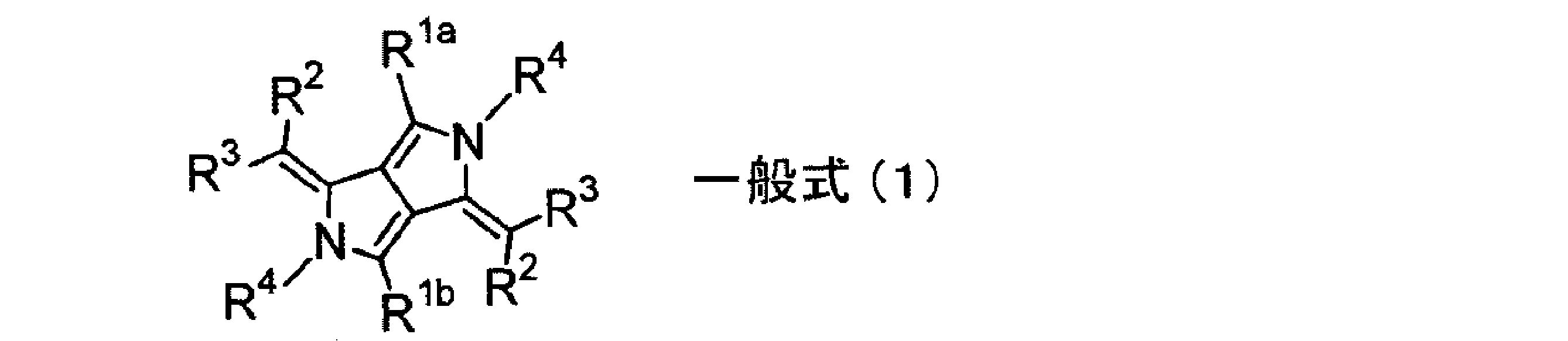
(一般式(1)中、R1a及びR1bは互いに同じであっても異なっていてもよく、各々独立にアルキル基、アリール基またはヘテロアリール基を表す。R2およびR3は各々独立に水素原子または置換基を表し、R2およびR3のうち少なくとも一方は電子吸引性基であり、R2およびR3は互いに結合して環を形成してもよい。R4は水素原子、アルキル基、アリール基、ヘテロアリール基、置換ホウ素または金属原子を表し、R4はR1a、R1bおよびR3のうち少なくとも一方と共有結合または配位結合してもよい。)
[2] [1]に記載の赤外線カットフィルムは、前記近赤外線吸収剤は、極大吸収波長における吸光度が1のときに、550nmの吸光度が0.1以下であることが好ましい。
[3] [1]または[2]に記載の赤外線カットフィルムは、前記近赤外線吸収剤が、前記一般式(1)で表される化合物の微粒子の分散状態であることが好ましい。
[4] [3]に記載の赤外線カットフィルムは、前記一般式(1)で表される化合物の微粒子の数平均粒径が5~500nmであることが好ましい。
[5] [3]または[4]に記載の赤外線カットフィルムは、前記近赤外線吸収層は、紫外線硬化型樹脂または熱可塑性樹脂に、前記一般式(1)で表される化合物の微粒子が分散されたことが好ましい。
[6] [1]~[5]のいずれか一項に記載の赤外線カットフィルムは、前記近赤外線吸収層が、塗布により形成されてなることが好ましい。
[7] [1]~[6]のいずれか一項に記載の赤外線カットフィルムは、前記近赤外線反射層のうち少なくとも1層は750nm~1100nmにおける反射率の極大値が40%以上であることが好ましい。
[8] [1]~[7]のいずれか一項に記載の赤外線カットフィルムは、前記近赤外線反射層は、重合性液晶からなるコレステリック液晶を塗布し、配向させたのちに光重合によって固定化されてなることが好ましい。
[9] [1]~[8]のいずれか一項に記載の赤外線カットフィルムは、前記近赤外線反射層が、互いに逆方向の円偏光を反射し、反射波長域が750nm~900nmにあって、中心反射波長が互いに等しい、2層のコレステリック液晶相が固定化された反射層を含むことが好ましい。
[10] [1]~[9]のいずれか一項に記載の赤外線カットフィルムは、さらに金属微粒子分散物およびジインモニウム色素のうち少なくとも一方を含むことが好ましい。
[11] [10]に記載の赤外線カットフィルムは、前記金属微粒子分散物が、下記一般式(I)で表される複合タングステン酸化物であることが好ましい。
MxWOy・・・(I)
(M元素はCs、Na、Rb、K、Tl、In、Ba、Li、Ca、Sr、Fe、およびSnからなる群から選ばれる少なくとも1種、Wはタングステン、Oは酸素で、0.1≦x≦0.5、2.2≦y≦3.0)
[12] [1]~[11]のいずれか一項に記載の赤外線カットフィルムは、易接着層、ハードコート層、紫外線吸収層、粘着層および表面保護層のうち少なくとも1つをさらに有することが好ましい。
[13] 2枚のガラス板と、その間に挟持された[1]~[12]のいずれか一項に記載の赤外線カットフィルムとを有することを特徴とする赤外線カット合わせガラス。
[14] [1]~[12]のいずれか一項に記載の赤外線カットフィルムを含み、建造物および車両の窓への張り合わせ用であることを特徴とする赤外線カット部材。
[15] [1]~[12]のいずれか一項に記載の赤外線カットフィルムを含み、車両のフロントガラス用であることを特徴とする赤外線カット部材。
[1] 透明基材と、極大吸収波長が750nm~920nmである近赤外線吸収剤を含む近赤外線吸収層と、コレステリック液晶相を固定化してなる少なくとも1層の近赤外線反射層とを有し、前記近赤外線吸収剤が、下記一般式(1)で表される化合物であることを特徴とする赤外線カットフィルム。
[2] [1]に記載の赤外線カットフィルムは、前記近赤外線吸収剤は、極大吸収波長における吸光度が1のときに、550nmの吸光度が0.1以下であることが好ましい。
[3] [1]または[2]に記載の赤外線カットフィルムは、前記近赤外線吸収剤が、前記一般式(1)で表される化合物の微粒子の分散状態であることが好ましい。
[4] [3]に記載の赤外線カットフィルムは、前記一般式(1)で表される化合物の微粒子の数平均粒径が5~500nmであることが好ましい。
[5] [3]または[4]に記載の赤外線カットフィルムは、前記近赤外線吸収層は、紫外線硬化型樹脂または熱可塑性樹脂に、前記一般式(1)で表される化合物の微粒子が分散されたことが好ましい。
[6] [1]~[5]のいずれか一項に記載の赤外線カットフィルムは、前記近赤外線吸収層が、塗布により形成されてなることが好ましい。
[7] [1]~[6]のいずれか一項に記載の赤外線カットフィルムは、前記近赤外線反射層のうち少なくとも1層は750nm~1100nmにおける反射率の極大値が40%以上であることが好ましい。
[8] [1]~[7]のいずれか一項に記載の赤外線カットフィルムは、前記近赤外線反射層は、重合性液晶からなるコレステリック液晶を塗布し、配向させたのちに光重合によって固定化されてなることが好ましい。
[9] [1]~[8]のいずれか一項に記載の赤外線カットフィルムは、前記近赤外線反射層が、互いに逆方向の円偏光を反射し、反射波長域が750nm~900nmにあって、中心反射波長が互いに等しい、2層のコレステリック液晶相が固定化された反射層を含むことが好ましい。
[10] [1]~[9]のいずれか一項に記載の赤外線カットフィルムは、さらに金属微粒子分散物およびジインモニウム色素のうち少なくとも一方を含むことが好ましい。
[11] [10]に記載の赤外線カットフィルムは、前記金属微粒子分散物が、下記一般式(I)で表される複合タングステン酸化物であることが好ましい。
MxWOy・・・(I)
(M元素はCs、Na、Rb、K、Tl、In、Ba、Li、Ca、Sr、Fe、およびSnからなる群から選ばれる少なくとも1種、Wはタングステン、Oは酸素で、0.1≦x≦0.5、2.2≦y≦3.0)
[12] [1]~[11]のいずれか一項に記載の赤外線カットフィルムは、易接着層、ハードコート層、紫外線吸収層、粘着層および表面保護層のうち少なくとも1つをさらに有することが好ましい。
[13] 2枚のガラス板と、その間に挟持された[1]~[12]のいずれか一項に記載の赤外線カットフィルムとを有することを特徴とする赤外線カット合わせガラス。
[14] [1]~[12]のいずれか一項に記載の赤外線カットフィルムを含み、建造物および車両の窓への張り合わせ用であることを特徴とする赤外線カット部材。
[15] [1]~[12]のいずれか一項に記載の赤外線カットフィルムを含み、車両のフロントガラス用であることを特徴とする赤外線カット部材。
本発明によると、不可視性および堅牢性がともに優れ、遮熱性能の高い赤外線カットフィルムを提供することができる。
以下、本発明の赤外線カットフィルム、赤外線カット合わせガラスおよび赤外線カット部材の好ましい態様について説明する。
以下に記載する構成要件の説明は、本発明の代表的な実施態様に基づいてなされることがあるが、本発明はそのような実施態様に限定されるものではない。なお、本明細書において「~」を用いて表される数値範囲は、「~」の前後に記載される数値を下限値および上限値として含む範囲を意味する。
以下に記載する構成要件の説明は、本発明の代表的な実施態様に基づいてなされることがあるが、本発明はそのような実施態様に限定されるものではない。なお、本明細書において「~」を用いて表される数値範囲は、「~」の前後に記載される数値を下限値および上限値として含む範囲を意味する。
[赤外線カットフィルム]
本発明の赤外線カットフィルムは、透明基材と、極大吸収波長が750nm~920nmである近赤外線吸収剤を含む近赤外線吸収層と、コレステリック液晶相を固定化してなる少なくとも1層の近赤外線反射層とを有し、前記近赤外線吸収剤が、下記一般式(1)で表される化合物であることを特徴とする。

(一般式(1)中、R1a及びR1bは互いに同じであっても異なっていてもよく、各々独立にアルキル基、アリール基またはヘテロアリール基を表す。R2およびR3は各々独立に水素原子または置換基を表し、R2およびR3のうち少なくとも一方は電子吸引性基であり、R2およびR3は互いに結合して環を形成してもよい。R4は水素原子、アルキル基、アリール基、ヘテロアリール基、置換ホウ素または金属原子を表し、R4はR1a、R1bおよびR3のうち少なくとも一方と共有結合または配位結合してもよい。)
このような構成により、本発明の赤外線カットフィルムは不可視性および堅牢性がともに優れ、遮熱性能が高い。
以下、本発明の赤外線カットフィルムのより好ましい態様について、具体的に説明する。
本発明の赤外線カットフィルムは、透明基材と、極大吸収波長が750nm~920nmである近赤外線吸収剤を含む近赤外線吸収層と、コレステリック液晶相を固定化してなる少なくとも1層の近赤外線反射層とを有し、前記近赤外線吸収剤が、下記一般式(1)で表される化合物であることを特徴とする。
このような構成により、本発明の赤外線カットフィルムは不可視性および堅牢性がともに優れ、遮熱性能が高い。
以下、本発明の赤外線カットフィルムのより好ましい態様について、具体的に説明する。
<赤外線カットフィルムの特性>
本発明の赤外線カットフィルムの可視光線透過率としては、60%以上であることが好ましく、65%以上であることがより好ましく、70%以上であることが特に好ましい。前記可視光線透過率が、70%以上であると、例えば、自動車用ガラスや建物用ガラスとして用いた時に、外部が見やすい。
本発明の赤外線カットフィルムの可視光線透過率としては、60%以上であることが好ましく、65%以上であることがより好ましく、70%以上であることが特に好ましい。前記可視光線透過率が、70%以上であると、例えば、自動車用ガラスや建物用ガラスとして用いた時に、外部が見やすい。
<赤外線カットフィルムの構成>
本発明の赤外線カットフィルムの構成の一例を図面により説明する。ただし、本発明は図面により限定されるものではない。
図1は、本発明の赤外線カットフィルムの一例を示した概略図であり、透明基材12の上に、2層のコレステリック液晶層を固定化してなる近赤外線反射層14aおよび14bが積層されており、その上に近赤外線吸収剤を含む近赤外線吸収層19が積層されている。透明基材12、コレステリック液晶層を固定化してなる近赤外線反射層14aおよび14b、ならびに、近赤外線吸収剤を含む近赤外線吸収層19の積層順に特に制限はない。
図2は、本発明の赤外線カットフィルムの他の一例を示した概略図であり、透明基材12の上に、2層のコレステリック液晶層を固定化してなる近赤外線反射層14aおよび14bが積層されており、その上に近赤外線吸収剤を含む近赤外線吸収層19が積層されており、さらにその上に金属微粒子分散物またはジインモニウム色素を含む他の赤外線吸収層20が積層されている。金属微粒子分散物またはジインモニウム色素を含む他の赤外線吸収層20は、赤外線吸収機能のみを奏する赤外線吸収層であっても、他の機能層を兼ねる層であってもよい。他の機能層を兼ねる層としては例えば、ジインモニウム色素を混合した合わせガラス中間膜に対する易接着層とする態様などを挙げることができる。
本発明の赤外線カットフィルムの構成の一例を図面により説明する。ただし、本発明は図面により限定されるものではない。
図1は、本発明の赤外線カットフィルムの一例を示した概略図であり、透明基材12の上に、2層のコレステリック液晶層を固定化してなる近赤外線反射層14aおよび14bが積層されており、その上に近赤外線吸収剤を含む近赤外線吸収層19が積層されている。透明基材12、コレステリック液晶層を固定化してなる近赤外線反射層14aおよび14b、ならびに、近赤外線吸収剤を含む近赤外線吸収層19の積層順に特に制限はない。
図2は、本発明の赤外線カットフィルムの他の一例を示した概略図であり、透明基材12の上に、2層のコレステリック液晶層を固定化してなる近赤外線反射層14aおよび14bが積層されており、その上に近赤外線吸収剤を含む近赤外線吸収層19が積層されており、さらにその上に金属微粒子分散物またはジインモニウム色素を含む他の赤外線吸収層20が積層されている。金属微粒子分散物またはジインモニウム色素を含む他の赤外線吸収層20は、赤外線吸収機能のみを奏する赤外線吸収層であっても、他の機能層を兼ねる層であってもよい。他の機能層を兼ねる層としては例えば、ジインモニウム色素を混合した合わせガラス中間膜に対する易接着層とする態様などを挙げることができる。
<透明基材>
本発明の赤外線カットフィルムは、透明基材を有する。
前記支持体としては特に制限は無く公知の透明基材を用いることができる。
前記透明基材としては、光学的に透明な透明基材であれば特に制限はなく、目的に応じて適宜選択することができ、例えば、可視光線透過率が70%以上のもの、好ましくは80%以上のもの、近赤外線域の透過率が高いものなどが挙げられる。
前記透明基材としては、その形状、構造、大きさ、材料などについては、特に制限はなく、目的に応じて適宜選択することができる。前記形状としては、例えば、平板状などが挙げられ、前記構造としては、単層構造であってもよいし、積層構造であってもよく、前記大きさとしては、前記赤外線カットフィルムの大きさなどに応じて適宜選択することができる。
前記透明基材の材料としては、特に制限はなく、目的に応じて適宜選択することができ、例えば、ポリエチレン、ポリプロピレン、ポリ4-メチルペンテン-1、ポリブテン-1等のポリオレフィン系樹脂;ポリエチレンテレフタレート、ポリエチレンナフタレート等のポリエステル系樹脂;ポリカーボネート系樹脂、ポリ塩化ビニル系樹脂、ポリフェニレンサルファイド系樹脂、ポリエーテルサルフォン系樹脂、ポリエチレンサルファイド系樹脂、ポリフェニレンエーテル系樹脂、スチレン系樹脂、アクリル系樹脂、ポリアミド系樹脂、ポリイミド系樹脂、セルロースアセテート等のセルロース系樹脂などからなるフィルム又はこれらの積層フィルムが挙げられる。これらの中で、特にポリエチレンテレフタレートフィルムが好適である。
前記透明基材の厚みとしては、特に制限はなく、赤外線カットフィルムの使用目的に応じて適宜選択することができ、通常は10μm~500μm程度であるが薄膜化の要請の観点からはより薄い方が好ましい。前記透明基材の厚みは10μm~100μmであることが好ましく、20~75μmであることがより好ましく、35~75μmであることが特に好ましい。前記支持体の厚みが十分に厚いと、接着故障が起き難くなる傾向にある。また、前記透明基材の厚みが十分に薄いと、赤外線カットフィルムとして建材や自動車に貼り合わせる際、材料としての腰が強過ぎず、施工し易くなる傾向にある。更に、透明基材が十分に薄いことにより、可視光透過率が増加し、原材料費を抑制できる傾向にある。
本発明の赤外線カットフィルムは、透明基材を有する。
前記支持体としては特に制限は無く公知の透明基材を用いることができる。
前記透明基材としては、光学的に透明な透明基材であれば特に制限はなく、目的に応じて適宜選択することができ、例えば、可視光線透過率が70%以上のもの、好ましくは80%以上のもの、近赤外線域の透過率が高いものなどが挙げられる。
前記透明基材としては、その形状、構造、大きさ、材料などについては、特に制限はなく、目的に応じて適宜選択することができる。前記形状としては、例えば、平板状などが挙げられ、前記構造としては、単層構造であってもよいし、積層構造であってもよく、前記大きさとしては、前記赤外線カットフィルムの大きさなどに応じて適宜選択することができる。
前記透明基材の材料としては、特に制限はなく、目的に応じて適宜選択することができ、例えば、ポリエチレン、ポリプロピレン、ポリ4-メチルペンテン-1、ポリブテン-1等のポリオレフィン系樹脂;ポリエチレンテレフタレート、ポリエチレンナフタレート等のポリエステル系樹脂;ポリカーボネート系樹脂、ポリ塩化ビニル系樹脂、ポリフェニレンサルファイド系樹脂、ポリエーテルサルフォン系樹脂、ポリエチレンサルファイド系樹脂、ポリフェニレンエーテル系樹脂、スチレン系樹脂、アクリル系樹脂、ポリアミド系樹脂、ポリイミド系樹脂、セルロースアセテート等のセルロース系樹脂などからなるフィルム又はこれらの積層フィルムが挙げられる。これらの中で、特にポリエチレンテレフタレートフィルムが好適である。
前記透明基材の厚みとしては、特に制限はなく、赤外線カットフィルムの使用目的に応じて適宜選択することができ、通常は10μm~500μm程度であるが薄膜化の要請の観点からはより薄い方が好ましい。前記透明基材の厚みは10μm~100μmであることが好ましく、20~75μmであることがより好ましく、35~75μmであることが特に好ましい。前記支持体の厚みが十分に厚いと、接着故障が起き難くなる傾向にある。また、前記透明基材の厚みが十分に薄いと、赤外線カットフィルムとして建材や自動車に貼り合わせる際、材料としての腰が強過ぎず、施工し易くなる傾向にある。更に、透明基材が十分に薄いことにより、可視光透過率が増加し、原材料費を抑制できる傾向にある。
<近赤外線吸収剤を含む近赤外線吸収層>
本発明の赤外線カットフィルムは、極大吸収波長が750nm~920nmである近赤外線吸収剤を含む近赤外線吸収層を有し、前記近赤外線吸収剤が、下記一般式(1)で表される化合物であることを特徴とする。

(一般式(1)中、R1a及びR1bは互いに同じであっても異なっていてもよく、各々独立にアルキル基、アリール基またはヘテロアリール基を表す。R2およびR3は各々独立に水素原子または置換基を表し、R2およびR3のうち少なくとも一方は電子吸引性基であり、R2およびR3は互いに結合して環を形成してもよい。R4は水素原子、アルキル基、アリール基、ヘテロアリール基、置換ホウ素または金属原子を表し、R4はR1a、R1bおよびR3のうち少なくとも一方と共有結合または配位結合してもよい。)
本発明の赤外線カットフィルムは、極大吸収波長が750nm~920nmである近赤外線吸収剤を含む近赤外線吸収層を有し、前記近赤外線吸収剤が、下記一般式(1)で表される化合物であることを特徴とする。
(近赤外線吸収剤)
前記近赤外線吸収層は、極大吸収波長が750nm~920nmである近赤外線吸収剤を用いる。前記近赤外線吸収剤の極大吸収波長は、770nm~900nmであることが好ましく、780nm~900nmであることがより好ましい。
前記近赤外線吸収層は、極大吸収波長が750nm~920nmである近赤外線吸収剤を用いる。前記近赤外線吸収剤の極大吸収波長は、770nm~900nmであることが好ましく、780nm~900nmであることがより好ましい。
前記近赤外線吸収剤は極大吸収波長における吸光度が1のときに、550nmの吸光度が0.1以下であることが、不可視性を向上させ、近赤外吸収層の可視光透過率の値を大きくする観点から好ましい。
以下、前記近赤外線吸収剤として用いられる、前記一般式(1)で表される化合物のより好ましい構造について説明する。
一般式(1)中、R1a、R1bで表されるアルキル基としては、好ましくは炭素数1~30、より好ましくは炭素数1~20、特に好ましくは炭素数1~10のアルキル基である。例えば、メチル、エチル、iso-プロピル、tert-ブチル、n-オクチル、n-デシル、n-ヘキサデシル、2-メチルブチル、2-エチルシクロへキシル、シクロペンチル、シクロヘキシルなどを挙げることができる。
R1a、R1bで表されるアリール基としては、好ましくは炭素数6~30、より好ましくは炭素数6~20、特に好ましくは炭素数6~12のアリール基である。例えば、フェニル、o-メチルフェニル、p-メチルフェニル、ビフェニル、ナフチル、アントラニル、フェナントリル、4-アルコキシフェニル(例えば、4-(2-エチルヘキシルオキシ)フェニル、4-(2-メチルブチルオキシ)フェニル、4-(2-オクチルドデシルオキシ)フェニルなど)、4-ヒドロキシフェニルなどを挙げることができる。
R1a、R1bで表されるヘテロアリール基としては、好ましくは炭素数1~30、より好ましくは炭素数1~12のヘテロアリール基である。ヘテロ原子としては、例えば、窒素原子、酸素原子、硫黄原子を挙げることができる。ヘテロアリール基として具体的には、例えば、イミダゾリル、ピリジル、キノリル、フリル、チエニル、ベンズオキサゾリル、ベンズイミダゾリル、ベンズチアゾリル、ナフトチアゾリル、ベンズオキサゾリ、m-カルバゾリル、アゼピニルなどを挙げることができる。
R1a、R1bで表される基としては、アリール基が好ましく、o-メチルフェニルまたは4-アルコキシフェニルがより好ましく、4-アルコキシフェニルが特に好ましい。前記4-アルコキシフェニル基中のアルコキシ基の炭素数は1~10であることが好ましく、1~8であることがより好ましく、分散性を高めて会合させやすくし、吸収を長波長側にシフトさせる観点から1~6であることが特に好ましく、4-(2-メチルブチルオキシ)フェニルがより特に好ましい。また、前記4-アルコキシフェニル基中のアルコキシ基は分枝のアルコキシ基であることが好ましい。
一般式(1)中のR1a及びR1bは、互いに同一でも異なっていてもよい。
R1a、R1bで表されるアリール基としては、好ましくは炭素数6~30、より好ましくは炭素数6~20、特に好ましくは炭素数6~12のアリール基である。例えば、フェニル、o-メチルフェニル、p-メチルフェニル、ビフェニル、ナフチル、アントラニル、フェナントリル、4-アルコキシフェニル(例えば、4-(2-エチルヘキシルオキシ)フェニル、4-(2-メチルブチルオキシ)フェニル、4-(2-オクチルドデシルオキシ)フェニルなど)、4-ヒドロキシフェニルなどを挙げることができる。
R1a、R1bで表されるヘテロアリール基としては、好ましくは炭素数1~30、より好ましくは炭素数1~12のヘテロアリール基である。ヘテロ原子としては、例えば、窒素原子、酸素原子、硫黄原子を挙げることができる。ヘテロアリール基として具体的には、例えば、イミダゾリル、ピリジル、キノリル、フリル、チエニル、ベンズオキサゾリル、ベンズイミダゾリル、ベンズチアゾリル、ナフトチアゾリル、ベンズオキサゾリ、m-カルバゾリル、アゼピニルなどを挙げることができる。
R1a、R1bで表される基としては、アリール基が好ましく、o-メチルフェニルまたは4-アルコキシフェニルがより好ましく、4-アルコキシフェニルが特に好ましい。前記4-アルコキシフェニル基中のアルコキシ基の炭素数は1~10であることが好ましく、1~8であることがより好ましく、分散性を高めて会合させやすくし、吸収を長波長側にシフトさせる観点から1~6であることが特に好ましく、4-(2-メチルブチルオキシ)フェニルがより特に好ましい。また、前記4-アルコキシフェニル基中のアルコキシ基は分枝のアルコキシ基であることが好ましい。
一般式(1)中のR1a及びR1bは、互いに同一でも異なっていてもよい。
R2及びR3は各々独立に水素原子または置換基Tを表し、少なくとも一方は電子吸引性基であり、R2及びR3は結合して環を形成していてもよい。置換基Tとしては例えば、以下のものを挙げることができる。これらの置換基は更に置換されていてもよい。
・アルキル基(好ましくは炭素数1~30、より好ましくは炭素数1~20、特に好ましくは炭素数1~10であり、例えばメチル、エチル、iso-プロピル、tert-ブチル、n-オクチル、n-デシル、n-ヘキサデシル、2-メチルブチル、2-エチルシクロへキシル、シクロペンチル、シクロヘキシルなどが挙げられる。)
・アルケニル基(好ましくは炭素数2~30、より好ましくは炭素数2~20、特に好ましくは炭素数2~10であり、例えばビニル、アリル、2-ブテニル、3-ペンテニルなどが挙げられる。)
・アルキニル基(好ましくは炭素数2~30、より好ましくは炭素数2~20、特に好ましくは炭素数2~10であり、例えばプロパルギル、3-ペンチニルなどが挙げられる。
・アリール基(好ましくは炭素数6~30、より好ましくは炭素数6~20、特に好ましくは炭素数6~12であり、例えばフェニル、p-メチルフェニル、ビフェニル、ナフチル、アントラニル、フェナントリルなどが挙げられる。)
・アミノ基(好ましくは炭素数0~30、より好ましくは炭素数0~20、特に好ましくは炭素数0~10であり、アルキルアミノ基、アリールアミノ基、ヘテロ環アミノ基を含み、例えばアミノ、メチルアミノ、ジメチルアミノ、ジエチルアミノ、ジベンジルアミノ、ジフェニルアミノ、ジトリルアミノなどが挙げられる。)
・アルコキシ基(好ましくは炭素数1~30、より好ましくは炭素数1~20、特に好ましくは炭素数1~10であり、例えばメトキシ、エトキシ、ブトキシ、2-エチルヘキシロキシなどが挙げられる。)
・アリールオキシ基(好ましくは炭素数6~30、より好ましくは炭素数6~20、特に好ましくは炭素数6~12であり、例えばフェニルオキシ、1-ナフチルオキシ、2-ナフチルオキシなどが挙げられる。)
・芳香族ヘテロ環オキシ基(好ましくは炭素数1~30、より好ましくは炭素数1~20、特に好ましくは炭素数1~12であり、例えばピリジルオキシ、ピラジルオキシ、ピリミジルオキシ、キノリルオキシなどが挙げられる。)
・アルキル基(好ましくは炭素数1~30、より好ましくは炭素数1~20、特に好ましくは炭素数1~10であり、例えばメチル、エチル、iso-プロピル、tert-ブチル、n-オクチル、n-デシル、n-ヘキサデシル、2-メチルブチル、2-エチルシクロへキシル、シクロペンチル、シクロヘキシルなどが挙げられる。)
・アルケニル基(好ましくは炭素数2~30、より好ましくは炭素数2~20、特に好ましくは炭素数2~10であり、例えばビニル、アリル、2-ブテニル、3-ペンテニルなどが挙げられる。)
・アルキニル基(好ましくは炭素数2~30、より好ましくは炭素数2~20、特に好ましくは炭素数2~10であり、例えばプロパルギル、3-ペンチニルなどが挙げられる。
・アリール基(好ましくは炭素数6~30、より好ましくは炭素数6~20、特に好ましくは炭素数6~12であり、例えばフェニル、p-メチルフェニル、ビフェニル、ナフチル、アントラニル、フェナントリルなどが挙げられる。)
・アミノ基(好ましくは炭素数0~30、より好ましくは炭素数0~20、特に好ましくは炭素数0~10であり、アルキルアミノ基、アリールアミノ基、ヘテロ環アミノ基を含み、例えばアミノ、メチルアミノ、ジメチルアミノ、ジエチルアミノ、ジベンジルアミノ、ジフェニルアミノ、ジトリルアミノなどが挙げられる。)
・アルコキシ基(好ましくは炭素数1~30、より好ましくは炭素数1~20、特に好ましくは炭素数1~10であり、例えばメトキシ、エトキシ、ブトキシ、2-エチルヘキシロキシなどが挙げられる。)
・アリールオキシ基(好ましくは炭素数6~30、より好ましくは炭素数6~20、特に好ましくは炭素数6~12であり、例えばフェニルオキシ、1-ナフチルオキシ、2-ナフチルオキシなどが挙げられる。)
・芳香族ヘテロ環オキシ基(好ましくは炭素数1~30、より好ましくは炭素数1~20、特に好ましくは炭素数1~12であり、例えばピリジルオキシ、ピラジルオキシ、ピリミジルオキシ、キノリルオキシなどが挙げられる。)
・アシル基(好ましくは炭素数1~30、より好ましくは炭素数1~20、特に好ましくは炭素数1~12であり、例えばアセチル、ベンゾイル、ホルミル、ピバロイルなどが挙げられる。)
・アルコキシカルボニル基(好ましくは炭素数2~30、より好ましくは炭素数2~20、特に好ましくは炭素数2~12であり、例えばメトキシカルボニル、エトキシカルボニルなどが挙げられる。)
・アリールオキシカルボニル基(好ましくは炭素数7~30、より好ましくは炭素数7~20、特に好ましくは炭素数7~12であり、例えばフェニルオキシカルボニルなどが挙げられる。)
・アシルオキシ基(好ましくは炭素数2~30、より好ましくは炭素数2~20、特に好ましくは炭素数2~10であり、例えばアセトキシ、ベンゾイルオキシなどが挙げられる。)
・アシルアミノ基(好ましくは炭素数2~30、より好ましくは炭素数2~20、特に好ましくは炭素数2~10であり、例えばアセチルアミノ、ベンゾイルアミノなどが挙げられる。)
・アルコキシカルボニルアミノ基(好ましくは炭素数2~30、より好ましくは炭素数2~20、特に好ましくは炭素数2~12であり、例えばメトキシカルボニルアミノなどが挙げられる。)
・アリールオキシカルボニルアミノ基(好ましくは炭素数7~30、より好ましくは炭素数7~20、特に好ましくは炭素数7~12であり、例えばフェニルオキシカルボニルアミノなどが挙げられる。)
・スルホニルアミノ基(好ましくは炭素数1~30、より好ましくは炭素数1~20、特に好ましくは炭素数1~12であり、例えばメタンスルホニルアミノ、ベンゼンスルホニルアミノなどが挙げられる。)
・スルファモイル基(好ましくは炭素数0~30、より好ましくは炭素数0~20、特に好ましくは炭素数0~12であり、例えばスルファモイル、メチルスルファモイル、ジメチルスルファモイル、フェニルスルファモイルなどが挙げられる。)
・カルバモイル基(好ましくは炭素数1~30、より好ましくは炭素数1~20、特に好ましくは炭素数1~12であり、例えばカルバモイル、メチルカルバモイル、ジエチルカルバモイル、フェニルカルバモイルなどが挙げられる。)
・アルキルチオ基(好ましくは炭素数1~30、より好ましくは炭素数1~20、特に好ましくは炭素数1~12であり、例えばメチルチオ、エチルチオなどが挙げられる。)
・アリールチオ基(好ましくは炭素数6~30、より好ましくは炭素数6~20、特に好ましくは炭素数6~12であり、例えばフェニルチオなどが挙げられる。)
・アルコキシカルボニル基(好ましくは炭素数2~30、より好ましくは炭素数2~20、特に好ましくは炭素数2~12であり、例えばメトキシカルボニル、エトキシカルボニルなどが挙げられる。)
・アリールオキシカルボニル基(好ましくは炭素数7~30、より好ましくは炭素数7~20、特に好ましくは炭素数7~12であり、例えばフェニルオキシカルボニルなどが挙げられる。)
・アシルオキシ基(好ましくは炭素数2~30、より好ましくは炭素数2~20、特に好ましくは炭素数2~10であり、例えばアセトキシ、ベンゾイルオキシなどが挙げられる。)
・アシルアミノ基(好ましくは炭素数2~30、より好ましくは炭素数2~20、特に好ましくは炭素数2~10であり、例えばアセチルアミノ、ベンゾイルアミノなどが挙げられる。)
・アルコキシカルボニルアミノ基(好ましくは炭素数2~30、より好ましくは炭素数2~20、特に好ましくは炭素数2~12であり、例えばメトキシカルボニルアミノなどが挙げられる。)
・アリールオキシカルボニルアミノ基(好ましくは炭素数7~30、より好ましくは炭素数7~20、特に好ましくは炭素数7~12であり、例えばフェニルオキシカルボニルアミノなどが挙げられる。)
・スルホニルアミノ基(好ましくは炭素数1~30、より好ましくは炭素数1~20、特に好ましくは炭素数1~12であり、例えばメタンスルホニルアミノ、ベンゼンスルホニルアミノなどが挙げられる。)
・スルファモイル基(好ましくは炭素数0~30、より好ましくは炭素数0~20、特に好ましくは炭素数0~12であり、例えばスルファモイル、メチルスルファモイル、ジメチルスルファモイル、フェニルスルファモイルなどが挙げられる。)
・カルバモイル基(好ましくは炭素数1~30、より好ましくは炭素数1~20、特に好ましくは炭素数1~12であり、例えばカルバモイル、メチルカルバモイル、ジエチルカルバモイル、フェニルカルバモイルなどが挙げられる。)
・アルキルチオ基(好ましくは炭素数1~30、より好ましくは炭素数1~20、特に好ましくは炭素数1~12であり、例えばメチルチオ、エチルチオなどが挙げられる。)
・アリールチオ基(好ましくは炭素数6~30、より好ましくは炭素数6~20、特に好ましくは炭素数6~12であり、例えばフェニルチオなどが挙げられる。)
・芳香族ヘテロ環チオ基(好ましくは炭素数1~30、より好ましくは炭素数1~20、特に好ましくは炭素数1~12であり、例えばピリジルチオ、2-ベンズイミゾリルチオ、2-ベンズオキサゾリルチオ、2-ベンズチアゾリルチオなどが挙げられる。)
・スルホニル基(好ましくは炭素数1~30、より好ましくは炭素数1~20、特に好ましくは炭素数1~12であり、例えばメシル、トシルなどが挙げられる。)
・スルフィニル基(好ましくは炭素数1~30、より好ましくは炭素数1~20、特に好ましくは炭素数1~12であり、例えばメタンスルフィニル、ベンゼンスルフィニルなどが挙げられる。)
・ウレイド基(好ましくは炭素数1~30、より好ましくは炭素数1~20、特に好ましくは炭素数1~12であり、例えばウレイド、メチルウレイド、フェニルウレイドなどが挙げられる。)
・リン酸アミド基(好ましくは炭素数1~30、より好ましくは炭素数1~20、特に好ましくは炭素数1~12であり、例えばジエチルリン酸アミド、フェニルリン酸アミドなどが挙げられる。)
・ヒドロキシ基
・メルカプト基
・ハロゲン原子(例えばフッ素原子、塩素原子、臭素原子、ヨウ素原子)
・シアノ基
・スルホ基
・カルボキシル基
・ニトロ基
・ヒドロキサム酸基
・スルフィノ基
・ヒドラジノ基
・イミノ基、
・ヘテロ環基(好ましくは炭素数1~30、より好ましくは炭素数1~12であり、ヘテロ原子としては、例えば窒素原子、酸素原子、硫黄原子、具体的には例えばイミダゾリル、ピリジル、キノリル、フリル、チエニル、ピペリジル、モルホリノ、ベンズオキサゾリル、ベンズイミダゾリル、ベンズチアゾリル、カルバゾリル基、アゼピニル基などが挙げられる。)
・シリル基(好ましくは炭素数3~40、より好ましくは炭素数3~30、特に好ましくは炭素数3~24であり、例えばトリメチルシリル、トリフェニルシリルなどが挙げられる。)
・スルホニル基(好ましくは炭素数1~30、より好ましくは炭素数1~20、特に好ましくは炭素数1~12であり、例えばメシル、トシルなどが挙げられる。)
・スルフィニル基(好ましくは炭素数1~30、より好ましくは炭素数1~20、特に好ましくは炭素数1~12であり、例えばメタンスルフィニル、ベンゼンスルフィニルなどが挙げられる。)
・ウレイド基(好ましくは炭素数1~30、より好ましくは炭素数1~20、特に好ましくは炭素数1~12であり、例えばウレイド、メチルウレイド、フェニルウレイドなどが挙げられる。)
・リン酸アミド基(好ましくは炭素数1~30、より好ましくは炭素数1~20、特に好ましくは炭素数1~12であり、例えばジエチルリン酸アミド、フェニルリン酸アミドなどが挙げられる。)
・ヒドロキシ基
・メルカプト基
・ハロゲン原子(例えばフッ素原子、塩素原子、臭素原子、ヨウ素原子)
・シアノ基
・スルホ基
・カルボキシル基
・ニトロ基
・ヒドロキサム酸基
・スルフィノ基
・ヒドラジノ基
・イミノ基、
・ヘテロ環基(好ましくは炭素数1~30、より好ましくは炭素数1~12であり、ヘテロ原子としては、例えば窒素原子、酸素原子、硫黄原子、具体的には例えばイミダゾリル、ピリジル、キノリル、フリル、チエニル、ピペリジル、モルホリノ、ベンズオキサゾリル、ベンズイミダゾリル、ベンズチアゾリル、カルバゾリル基、アゼピニル基などが挙げられる。)
・シリル基(好ましくは炭素数3~40、より好ましくは炭素数3~30、特に好ましくは炭素数3~24であり、例えばトリメチルシリル、トリフェニルシリルなどが挙げられる。)
R2及びR3のうち、少なくとも一方は電子吸引性基である。Hammettのσp値(シグマパラ値)が正の置換基は通常、電子吸引基として作用する。電子吸引基としては、好ましくはシアノ基、アシル基、アルキルオキシカルボニル基、アリールオキシカルボニル基、スルファモイル基、スルフィニル基、ヘテロ環基などが挙げられる。これらの電子吸引性基はさらに置換されていてもよい。
ハメットの置換基定数σ値について説明する。ハメット則は、ベンゼン誘導体の反応又は平衡に及ぼす置換基の影響を定量的に論ずるために1935年に、L.P.Hammettにより提唱された経験則であるが、これは今日広く妥当性が認められている。ハメット則で求められた置換基定数にはσp値とσm値がある。これらの値は多くの一般的な成書に見出すことができる。例えば、J.A.Dean編、「Lange’s Handbook of Chemistry」第12版,1979年(Mc Graw-Hill)や「化学の領域」増刊,122号,96~103頁,1979年(南光堂)、Chem.Rev.,1991年,91巻,165~195ページなどに記載されている。本発明においては、ハメットの置換基定数σp値が0.2以上の置換基を電子求引性基として例示することができる。σp値として好ましくは0.25以上であり、より好ましくは0.3以上であり、特に好ましくは0.35以上である。上限は特に制限はないが、好ましくは0.80である。
具体例としては、シアノ基(0.66)、カルボキシル基(-COOH:0.45)、アルコキシカルボニル基(-COOMe:0.45)、アリールオキシカルボニル基(-COOPh:0.44)、カルバモイル基(-CONH2:0.36)、アルキルカルボニル基(-COMe:0.50)、アリールカルボニル基(-COPh:0.43)、アルキルスルホニル基(-SO2Me:0.72)、またはアリールスルホニル基(-SO2Ph:0.68)などが挙げられる。特に好ましくは、シアノ基である。
本明細書において、Meはメチル基を、Phはフェニル基を表す。なお、括弧内の値は代表的な置換基のσp値をChem.Rev.,1991年,91巻,165~195ページから抜粋したものである。
本明細書において、Meはメチル基を、Phはフェニル基を表す。なお、括弧内の値は代表的な置換基のσp値をChem.Rev.,1991年,91巻,165~195ページから抜粋したものである。
さらに、R2及びR3が結合して環を形成する場合は、5ないし7員環(好ましくは5ないし6員環)の環を形成することが好ましい。形成される環としては通常メロシアニン色素で酸性核として用いられるものが好ましく、その具体例としては例えば以下のものが挙げられる。
(a)1,3-ジカルボニル核:例えば、1,3-インダンジオン核、1,3-シクロヘキサンジオン、5,5-ジメチル-1,3-シクロヘキサンジオン、1,3-ジオキサン-4,6-ジオンなど。
(b)ピラゾリノン核:例えば、1-フェニル-2-ピラゾリン-5-オン、3-メチル-1-フェニル-2-ピラゾリン-5-オン、1-(2-ベンゾチアゾイル)-3-メチル-2-ピラゾリン-5-オンなど。
(c)イソオキサゾリノン核:例えば、3-フェニル-2-イソオキサゾリン-5-オン、3-メチル-2-イソオキサゾリン-5-オンなど。
(d)オキシインドール核:例えば、1-アルキル-2,3-ジヒドロ-2-オキシインドールなど。
(e)2,4,6-トリケトヘキサヒドロピリミジン核:例えば、バルビツル酸または2-チオバルビツル酸およびその誘導体など。誘導体としては例えば1-メチル、1-エチル等の1-アルキル体、1,3-ジメチル、1,3-ジエチル、1,3-ジブチル等の1,3-ジアルキル体、1,3-ジフェニル、1,3-ジ(p-クロロフェニル)、1,3-ジ(p-エトキシカルボニルフェニル)等の1,3-ジアリール体、1-エチル-3-フェニル等の1-アルキル-1-アリール体、1,3-ジ(2-ピリジル)等の1,3位ジヘテロ環置換体等が挙げられる。
(f)2-チオ-2,4-チアゾリジンジオン核:例えば、ローダニンおよびその誘導体など。誘導体としては例えば3-メチルローダニン、3-エチルローダニン、3-アリルローダニン等の3-アルキルローダニン、3-フェニルローダニン等の3-アリールローダニン、3-(2-ピリジル)ローダニン等の3位ヘテロ環置換ローダニン等が挙げられる。
(g)2-チオ-2,4-オキサゾリジンジオン(2-チオ-2,4-(3H,5H)-オキサゾールジオン核:例えば、3-エチル-2-チオ-2,4-オキサゾリジンジオンなど。
(h)チアナフテノン核:例えば、3(2H)-チアナフテノン-1,1-ジオキサイドなど。
(i)2-チオ-2,5-チオゾリジンジオン核:例えば、3-エチル-2-チオ-2,5-チアゾリジンジオンなど。
(j)2,4-チオゾリジンジオン核:例えば、2,4-チアゾリジンジオン、3-エチル-2,4-チアゾリジンジオン、3-フェニル-2,4-チアゾリジンジオンなど。
(k)チアゾリン-4-オン核:例えば、4-チアゾリノン、2-エチル-4-チアゾリノンなど。
(l)4-チアゾリジノン核:例えば、2-エチルメルカプト-5-チアゾリン-4-オン、2-アルキルフェニルアミノ-5-チアゾリン-4-オンなど。
(m)2,4-イミダゾリジンジオン(ヒダントイン)核:例えば、2,4-イミダゾリジンジオン、3-エチル-2,4-イミダゾリジンジオンなど。
(n)2-チオ-2,4-イミダゾリジンジオン(2-チオヒダントイン)核:例えば、2-チオ-2,4-イミダゾリジンジオン、3-エチル-2-チオ-2,4-イミダゾリジンジオンなど。
(o)イミダゾリン-5-オン核:例えば、2-プロピルメルカプト-2-イミダゾリン-5-オンなど。
(p)3,5-ピラゾリジンジオン核:例えば、1,2-ジフェニル-3,5-ピラゾリジンジオン、1,2-ジメチル-3,5-ピラゾリジンジオンなど。
(q)ベンゾチオフェン-3-オン核:例えば、ベンゾチオフェン-3-オン、オキソベンゾチオフェンー3-オン、ジオキソベンゾチオフェンー3-オンなど。
(r)インダノン核:例えば、1-インダノン、3-フェニル-1-インダノン、3-メチル-1-インダノン、3,3-ジフェニル-1-インダノン、3,3-ジメチル-1-インダノンなど。
(a)1,3-ジカルボニル核:例えば、1,3-インダンジオン核、1,3-シクロヘキサンジオン、5,5-ジメチル-1,3-シクロヘキサンジオン、1,3-ジオキサン-4,6-ジオンなど。
(b)ピラゾリノン核:例えば、1-フェニル-2-ピラゾリン-5-オン、3-メチル-1-フェニル-2-ピラゾリン-5-オン、1-(2-ベンゾチアゾイル)-3-メチル-2-ピラゾリン-5-オンなど。
(c)イソオキサゾリノン核:例えば、3-フェニル-2-イソオキサゾリン-5-オン、3-メチル-2-イソオキサゾリン-5-オンなど。
(d)オキシインドール核:例えば、1-アルキル-2,3-ジヒドロ-2-オキシインドールなど。
(e)2,4,6-トリケトヘキサヒドロピリミジン核:例えば、バルビツル酸または2-チオバルビツル酸およびその誘導体など。誘導体としては例えば1-メチル、1-エチル等の1-アルキル体、1,3-ジメチル、1,3-ジエチル、1,3-ジブチル等の1,3-ジアルキル体、1,3-ジフェニル、1,3-ジ(p-クロロフェニル)、1,3-ジ(p-エトキシカルボニルフェニル)等の1,3-ジアリール体、1-エチル-3-フェニル等の1-アルキル-1-アリール体、1,3-ジ(2-ピリジル)等の1,3位ジヘテロ環置換体等が挙げられる。
(f)2-チオ-2,4-チアゾリジンジオン核:例えば、ローダニンおよびその誘導体など。誘導体としては例えば3-メチルローダニン、3-エチルローダニン、3-アリルローダニン等の3-アルキルローダニン、3-フェニルローダニン等の3-アリールローダニン、3-(2-ピリジル)ローダニン等の3位ヘテロ環置換ローダニン等が挙げられる。
(g)2-チオ-2,4-オキサゾリジンジオン(2-チオ-2,4-(3H,5H)-オキサゾールジオン核:例えば、3-エチル-2-チオ-2,4-オキサゾリジンジオンなど。
(h)チアナフテノン核:例えば、3(2H)-チアナフテノン-1,1-ジオキサイドなど。
(i)2-チオ-2,5-チオゾリジンジオン核:例えば、3-エチル-2-チオ-2,5-チアゾリジンジオンなど。
(j)2,4-チオゾリジンジオン核:例えば、2,4-チアゾリジンジオン、3-エチル-2,4-チアゾリジンジオン、3-フェニル-2,4-チアゾリジンジオンなど。
(k)チアゾリン-4-オン核:例えば、4-チアゾリノン、2-エチル-4-チアゾリノンなど。
(l)4-チアゾリジノン核:例えば、2-エチルメルカプト-5-チアゾリン-4-オン、2-アルキルフェニルアミノ-5-チアゾリン-4-オンなど。
(m)2,4-イミダゾリジンジオン(ヒダントイン)核:例えば、2,4-イミダゾリジンジオン、3-エチル-2,4-イミダゾリジンジオンなど。
(n)2-チオ-2,4-イミダゾリジンジオン(2-チオヒダントイン)核:例えば、2-チオ-2,4-イミダゾリジンジオン、3-エチル-2-チオ-2,4-イミダゾリジンジオンなど。
(o)イミダゾリン-5-オン核:例えば、2-プロピルメルカプト-2-イミダゾリン-5-オンなど。
(p)3,5-ピラゾリジンジオン核:例えば、1,2-ジフェニル-3,5-ピラゾリジンジオン、1,2-ジメチル-3,5-ピラゾリジンジオンなど。
(q)ベンゾチオフェン-3-オン核:例えば、ベンゾチオフェン-3-オン、オキソベンゾチオフェンー3-オン、ジオキソベンゾチオフェンー3-オンなど。
(r)インダノン核:例えば、1-インダノン、3-フェニル-1-インダノン、3-メチル-1-インダノン、3,3-ジフェニル-1-インダノン、3,3-ジメチル-1-インダノンなど。
環を形成する場合のR2及びR3のσp値を求めることはできないが、本発明においては、R2及びR3にそれぞれ環の部分構造が置換しているとみなして、環形成の場合のσp値を定義することとする。例えば1,3-インダンジオン環を形成している場合、R2及びR3にそれぞれベンゾイル基が置換したものとして考える。
R2及びR3が結合して形成される環としては、好ましくは1,3-ジカルボニル核、ピラゾリノン核、2,4,6-トリケトヘキサヒドロピリミジン核(チオケトン体も含む)、2-チオ-2,4-チアゾリジンジオン核、2-チオ-2,4-オキサゾリジンジオン核、2-チオ-2,5-チアゾリジンジオン核、2,4-チアゾリジンジオン核、2,4-イミダゾリジンジオン核、2-チオ-2,4-イミダゾリジンジオン核、2-イミダゾリン-5-オン核、3,5-ピラゾリジンジオン核、ベンゾチオフェン-3-オン核、またはインダノン核であり、更に好ましくは1,3-ジカルボニル核、2,4,6-トリケトヘキサヒドロピリミジン核(チオケトン体も含む)、3,5-ピラゾリジンジオン核、ベンゾチオフェン-3-オン核、またはインダノン核である。
R3はヘテロ環であることが特に好ましい。ヘテロ環として特に好ましくは、ピラゾール環、チアゾール環、オキサゾール環、イミダゾール環、オキサジアゾール環、チアジアゾール環、トリアゾール環、ピリジン環、ピリダジン環、ピリミジン環、ピラジン環、これらのベンゾ縮環もしくはナフト縮環、又はこれら縮環の複合体である。
一般式(1)中の2つのR3は、互いに同一でも異なってもよく、また、2つのR3は、互いに同一でも異なってもよい。
一般式(1)中の2つのR3は、互いに同一でも異なってもよく、また、2つのR3は、互いに同一でも異なってもよい。
R4で表される基がアルキル基、アリール基、又はヘテロアリール基であるとき、この基は、R1a、R1bで説明したものと同義であり、好ましい基も同様である。R4で表される基が置換ホウ素であるとき、その置換基は、R2及びR3について上述した置換基Tと同義であり、好ましくはアルキル基、アリール基、ヘテロアリール基である。また、R4で表される基が金属原子であるときは、好ましくは遷移金属、マグネシウム、アルミニウム、カルシウム、バリウム、亜鉛、又はスズであり、より好ましくはアルミニウム、亜鉛、スズ、バナジウム、鉄、コバルト、ニッケル、銅、パラジウム、イリジウム、又は白金であり、特に好ましくはアルミニウム、亜鉛、バナジウム、鉄、銅、パラジウム、イリジウム、又は白金である。
R4は特に好ましくは、置換ホウ素である。置換ホウ素として好ましくは、ジフルオロホウ素、ジフェニルホウ素、ジブチルホウ素、ジナフチルホウ素、カテコールホウ素が挙げられる。中でもジフェニルホウ素が特に好ましい。
R4は、R1a、R1b及び/又はR3と共有結合もしくは配位結合していてもよく、特にR4がR3と配位結合していることが好ましい。
一般式(1)中の2つのR4は、互いに同じでも異なっていてもよい。
R4は特に好ましくは、置換ホウ素である。置換ホウ素として好ましくは、ジフルオロホウ素、ジフェニルホウ素、ジブチルホウ素、ジナフチルホウ素、カテコールホウ素が挙げられる。中でもジフェニルホウ素が特に好ましい。
R4は、R1a、R1b及び/又はR3と共有結合もしくは配位結合していてもよく、特にR4がR3と配位結合していることが好ましい。
一般式(1)中の2つのR4は、互いに同じでも異なっていてもよい。
前記一般式(1)で表される化合物は、好ましくは下記一般式(2)、(3)又は(4)のいずれかで表される化合物であり、一般式(3)で表される化合物であることがより好ましい。
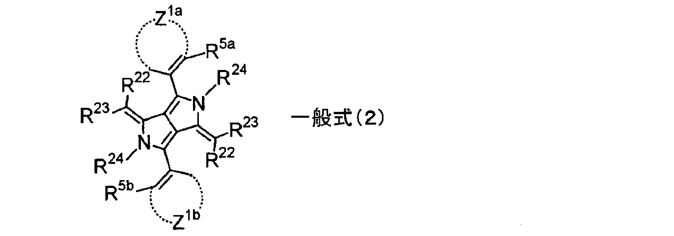
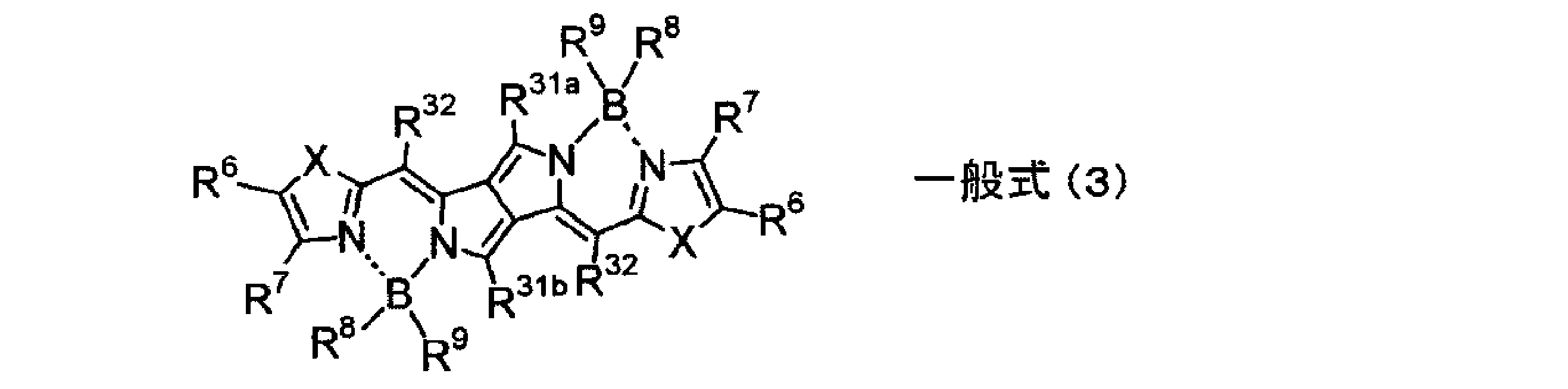

〈前記一般式(2)について〉
前記一般式(2)中、Z1a及びZ1bは各々独立にアリール環もしくはヘテロアリール環を形成する原子群を表す。形成されるアリール環、ヘテロアリール環は、前記一般式(1)におけるR2及びR3の置換基として説明したアリール基、ヘテロアリール基と同義であり、好ましい範囲も同様である。Z1a及びZ1bは同一であることが好ましい。
R5a及びR5bは各々独立に炭素数6~20のアリール基、炭素数4~20のヘテロアリール基、炭素数1~20のアルキル基、炭素数1~20のアルコキシ基、炭素数1~20のアルコキシカルボニル基、カルボキシル基、炭素数1~20のカルバモイル基、ハロゲン原子、又はシアノ基のいずれか1つを表す。具体例には、前記一般式(1)におけるR2及びR3で説明した例と同義であり、好ましい範囲も同様である。R5a及びR5bは互いに同じであることが好ましい。
R5a又はR5bとZ1a又はZ1bとが結合し縮合環を形成していてもよく、該縮合環としてはナフチル環、キノリン環などが挙げられる。
Z1a又はZ1bが形成するアリール環もしくはヘテロアリール環にR5a又はR5bで表される基を導入することで、不可視性を大きく向上させることができる。
前記一般式(2)中、Z1a及びZ1bは各々独立にアリール環もしくはヘテロアリール環を形成する原子群を表す。形成されるアリール環、ヘテロアリール環は、前記一般式(1)におけるR2及びR3の置換基として説明したアリール基、ヘテロアリール基と同義であり、好ましい範囲も同様である。Z1a及びZ1bは同一であることが好ましい。
R5a及びR5bは各々独立に炭素数6~20のアリール基、炭素数4~20のヘテロアリール基、炭素数1~20のアルキル基、炭素数1~20のアルコキシ基、炭素数1~20のアルコキシカルボニル基、カルボキシル基、炭素数1~20のカルバモイル基、ハロゲン原子、又はシアノ基のいずれか1つを表す。具体例には、前記一般式(1)におけるR2及びR3で説明した例と同義であり、好ましい範囲も同様である。R5a及びR5bは互いに同じであることが好ましい。
R5a又はR5bとZ1a又はZ1bとが結合し縮合環を形成していてもよく、該縮合環としてはナフチル環、キノリン環などが挙げられる。
Z1a又はZ1bが形成するアリール環もしくはヘテロアリール環にR5a又はR5bで表される基を導入することで、不可視性を大きく向上させることができる。
R22及びR23は各々独立にシアノ基、炭素数1~6のアシル基、炭素数1~6のアルコキシカルボニル基、炭素数1~10のアルキルもしくはアリールスルフィニル基、又は炭素数3~20の含窒素ヘテロアリール基を表し、又はR22及びR23が結合して環状酸性核を表す。具体的には、前記一般式(1)におけるR2及びR3で説明した例と同義であり、好ましい範囲も同様である。R4は前記一般式(1)におけるR4と同義であり、好ましい範囲も同様である。R4はR23と共有結合もしくは配位結合を有していてもよい。
前記一般式(2)で表される化合物は更に置換基を有していてもよく、該置換基としてはR2及びR3の置換基Tと同義であり、好ましい範囲も同様である。
前記一般式(2)における好ましい組合せとしては、Z1a及びZ1bが各々独立にベンゼン環もしくはピリジン環を形成し、R5a及びR5bは各々独立にアルキル基、アルコキシ基、ハロゲン原子、シアノ基であり、R22及びR23は各々独立にヘテロ環基、シアノ基、アシル基、アルコキシカルボニル基、又はR22及びR23が結合した環状酸性核であり、R4は水素原子、置換ホウ素、遷移金属原子、マグネシウム、アルミニウム、カルシウム、バリウム、亜鉛又はスズである。特に好ましい組合せとしては、Z1a及びZ1bが共にベンゼン環を形成し、R5a及びR5bが共にアルキル基、ハロゲン原子、又はシアノ基であり、R22及びR23が各々独立に含窒素ヘテロ環基とシアノ基もしくはアルコキシカルボニル基との組合せ、又はR22及びR23が結合した環状酸性核であり、R4が水素原子、置換ホウ素、アルミニウム、亜鉛、バナジウム、鉄、銅、パラジウム、イリジウム又は白金である。
前記一般式(2)における好ましい組合せとしては、Z1a及びZ1bが各々独立にベンゼン環もしくはピリジン環を形成し、R5a及びR5bは各々独立にアルキル基、アルコキシ基、ハロゲン原子、シアノ基であり、R22及びR23は各々独立にヘテロ環基、シアノ基、アシル基、アルコキシカルボニル基、又はR22及びR23が結合した環状酸性核であり、R4は水素原子、置換ホウ素、遷移金属原子、マグネシウム、アルミニウム、カルシウム、バリウム、亜鉛又はスズである。特に好ましい組合せとしては、Z1a及びZ1bが共にベンゼン環を形成し、R5a及びR5bが共にアルキル基、ハロゲン原子、又はシアノ基であり、R22及びR23が各々独立に含窒素ヘテロ環基とシアノ基もしくはアルコキシカルボニル基との組合せ、又はR22及びR23が結合した環状酸性核であり、R4が水素原子、置換ホウ素、アルミニウム、亜鉛、バナジウム、鉄、銅、パラジウム、イリジウム又は白金である。
〈前記一般式(3)について〉
一般式(3)中、R31a及びR31bは各々独立に炭素数1~20のアルキル基、炭素数6~20のアリール基または炭素数3~20のヘテロアリール基を表し、具体的には、前記一般式(1)におけるR1a及びR1bで説明した例と同義であり、好ましい範囲も同様である。R31a及びR31bは同一であることが好ましい。
R32はシアノ基、炭素数1~6のアルコキシカルボニル基、炭素数1~10のアルキルもしくはアリールスルフィニル基、又は炭素数3~10の含窒素ヘテロアリール基であり、具体的には、前記一般式(1)におけるR2の例と同義であり、好ましい範囲も同様である。
一般式(3)中、R31a及びR31bは各々独立に炭素数1~20のアルキル基、炭素数6~20のアリール基または炭素数3~20のヘテロアリール基を表し、具体的には、前記一般式(1)におけるR1a及びR1bで説明した例と同義であり、好ましい範囲も同様である。R31a及びR31bは同一であることが好ましい。
R32はシアノ基、炭素数1~6のアルコキシカルボニル基、炭素数1~10のアルキルもしくはアリールスルフィニル基、又は炭素数3~10の含窒素ヘテロアリール基であり、具体的には、前記一般式(1)におけるR2の例と同義であり、好ましい範囲も同様である。
R6及びR7は各々独立に水素原子、炭素数1~10のアルキル基、炭素数6~10のアリール基、炭素数4~10のヘテロアリール基であり、具体的には、前記一般式(1)におけるR2及びR3の置換基の例と同義であり、好ましい範囲も同様である。また、R6及びR7は結合して環を形成していてもよく、形成する環としては炭素数5~10の脂環、炭素数6~10のアリール環、炭素数3~10のヘテロアリール環であり、好ましい例としてはベンゼン環やナフタレン環、ピリジン環などが挙げられる。
R6及びR7が置換された5員含窒素ヘテロ環を導入し、更にホウ素錯体とすることで、堅牢性と不可視性の両方を併せ持つ近赤外吸収性色素を実現することができる。
R6及びR7が置換された5員含窒素ヘテロ環を導入し、更にホウ素錯体とすることで、堅牢性と不可視性の両方を併せ持つ近赤外吸収性色素を実現することができる。
R8及びR9は各々独立に炭素数1~10のアルキル基、炭素数1~10のアルコキシ基、炭素数6~20のアリール基又は炭素数3~10のヘテロアリール基であり、具体的には、前記一般式(1)におけるR2及びR3の置換基の例と同義であり、好ましい範囲も同様である。
Xは酸素原子、イオウ原子、-NR-、-CRR’-、-CH=CH-を表す。ここでR及びR’は各々独立に水素原子、炭素数1~10のアルキル基又は炭素数6~10のアリール基を表し、好ましくは水素原子、炭素数1~6のアルキル基又はフェニル基である。
Xは酸素原子、イオウ原子、-NR-、-CRR’-、-CH=CH-を表す。ここでR及びR’は各々独立に水素原子、炭素数1~10のアルキル基又は炭素数6~10のアリール基を表し、好ましくは水素原子、炭素数1~6のアルキル基又はフェニル基である。
前記一般式(3)における好ましい組合せとしては、R31a及びR31bが各々独立に炭素数1~10のアルキル基、ベンゼン環もしくはピリジン環であり、R32がシアノ基、アルコキシカルボニル基であり、R6及びR7が結合してベンゼン環もしくはピリジン環、ピラジン環、ピリミジン環を形成し、R8及びR9が各々独立に炭素原子1~6のアルキル基、フェニル基、ナフチル基であり、Xが酸素原子、イオウ原子、-NR-、-CRR’-又は-CH=CH-であり、R及びR’が各々独立に水素原子、炭素数1~6のアルキル基、フェニル基である。特に好ましい組合せとしては、R31a及びR31bが共に炭素数1~10のアルキル基またはベンゼン環であり、R32がシアノ基であり、R6及びR7が結合してベンゼン環もしくはピリジン環であり、R8及びR9が各々独立に炭素原子1~6のアルキル基、フェニル基、ナフチル基であり、Xが酸素、硫黄である。
〈前記一般式(4)について〉
一般式(4)中、R41a及びR41bは炭素数1~20のアルキル基、炭素数6~20のアリール基または炭素数3~20のヘテロアリール基を表し、具体的には、前記一般式(1)におけるR1a及びR1bで説明した例と同義であり、好ましい範囲も同様である。ただし、R41a及びR41bは互いに異なる基を表す。
R42はシアノ基、炭素数1~6のアルコキシカルボニル基、炭素数1~10のアルキルもしくはアリールスルフィニル基、又は炭素数3~10の含窒素ヘテロアリール基であり、具体的には、前記一般式(1)におけるR2の例と同義であり、好ましい範囲も同様である。
Z2は-C=N-と共に含窒素ヘテロ5又は6員環を形成する原子団を表し、含窒素ヘテロ環としてはピラゾール環、チアゾール環、オキサゾール環、イミダゾール環、オキサジアゾール環、チアジアゾール環、トリアゾール環、ピリジン環、ピリダジン環、ピリミジン環、ピラジン環、これらのベンゾ縮環もしくはナフト縮環、又はこれら縮環の複合体を表す。
R44は水素原子、炭素数1~20のアルキル基、炭素数6~20のアリール基、炭素数4~20のヘテロアリール基、金属原子または置換基としてハロゲン原子、炭素数1~10のアルキル基、炭素数6~20のアリール基、もしくは炭素数4~20のヘテロアリール基を有する置換ホウ素を表し、Z2が形成する含窒素ヘテロ環と共有結合もしくは配位結合を有していてもよい。
R41a及びR41bに互いに異なる基を導入するとともに、Z2と-C=N-により形成された含窒素ヘテロ5又は6員環を導入することで、堅牢性、不可視性、分散性および有機溶媒溶解性を満足することができる。
一般式(4)中、R41a及びR41bは炭素数1~20のアルキル基、炭素数6~20のアリール基または炭素数3~20のヘテロアリール基を表し、具体的には、前記一般式(1)におけるR1a及びR1bで説明した例と同義であり、好ましい範囲も同様である。ただし、R41a及びR41bは互いに異なる基を表す。
R42はシアノ基、炭素数1~6のアルコキシカルボニル基、炭素数1~10のアルキルもしくはアリールスルフィニル基、又は炭素数3~10の含窒素ヘテロアリール基であり、具体的には、前記一般式(1)におけるR2の例と同義であり、好ましい範囲も同様である。
Z2は-C=N-と共に含窒素ヘテロ5又は6員環を形成する原子団を表し、含窒素ヘテロ環としてはピラゾール環、チアゾール環、オキサゾール環、イミダゾール環、オキサジアゾール環、チアジアゾール環、トリアゾール環、ピリジン環、ピリダジン環、ピリミジン環、ピラジン環、これらのベンゾ縮環もしくはナフト縮環、又はこれら縮環の複合体を表す。
R44は水素原子、炭素数1~20のアルキル基、炭素数6~20のアリール基、炭素数4~20のヘテロアリール基、金属原子または置換基としてハロゲン原子、炭素数1~10のアルキル基、炭素数6~20のアリール基、もしくは炭素数4~20のヘテロアリール基を有する置換ホウ素を表し、Z2が形成する含窒素ヘテロ環と共有結合もしくは配位結合を有していてもよい。
R41a及びR41bに互いに異なる基を導入するとともに、Z2と-C=N-により形成された含窒素ヘテロ5又は6員環を導入することで、堅牢性、不可視性、分散性および有機溶媒溶解性を満足することができる。
前記一般式(4)における好ましい組合せとしては、R41a及びR41bが各々独立に炭素数1~10のアルキル基、ベンゼン環もしくはピリジン環であり、R42がシアノ基、炭素数1~10のアルキル、アリールスルフィニル基又はアルコキシカルボニル基であり、Z2が-C=N-と共にチアゾール環、オキサゾール環、イミダゾール環、チアジアゾール環、トリアゾール環、ピリジン環、ピリミジン環、ピラジン環、又はこれらのベンゾ縮環もしくはナフト縮環を形成し、R44が水素原子、置換ホウ素、遷移金属原子、マグネシウム、アルミニウム、カルシウム、バリウム、亜鉛又はスズである。特に好ましい組合せとしては、R41a及びR41bが各々独立に炭素数1~10のアルキル基またはベンゼン環であり、R42がシアノ基であり、Z2が-C=N-と共にチアゾール環、オキサゾール環、イミダゾール環、トリアゾール環、ピリジン環、ピリミジン環、又はこれらのベンゾ縮環もしくはナフト縮環を形成し、R44が水素原子、置換ホウ素(置換基としては炭素数1~10のアルキル基、ベンゼン環、ピリジン環又はチオフェン環)、アルミニウム、亜鉛、バナジウム、鉄、銅、パラジウム、イリジウム又は白金である。
以下に、前記一般式(1)で表される化合物の具体例を示すが、本発明は下記具体例に限定されるものではない。本明細書において、Meはメチル、Etはエチル基を、Buはブチル基、Phはフェニル基を表す。なお、以下の化学式において例えば式D-1やD-17等は一般式(1)の置換基R4にあたる水素原子が置換基R3を構成するヘテロ環の窒素原子と配位結合を形成するが、これを省略して示している(特開2011-68731号公報のスキーム1参照)。

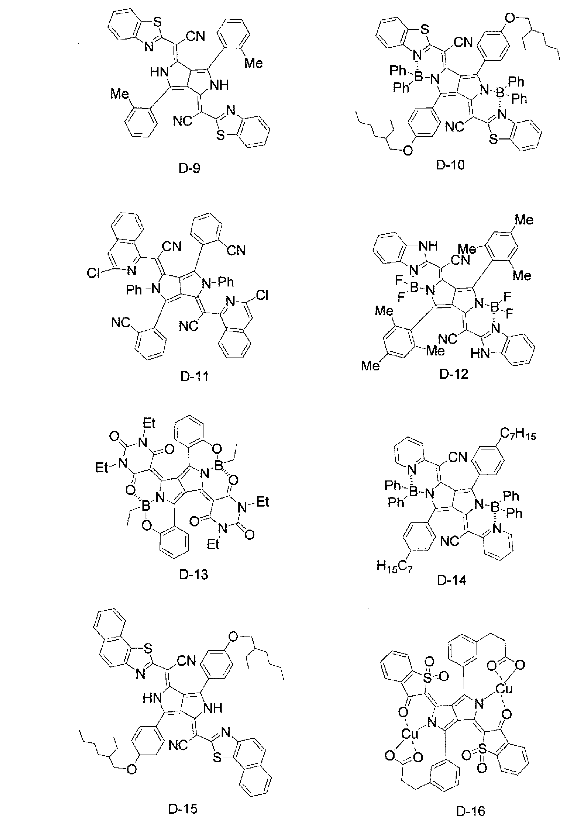


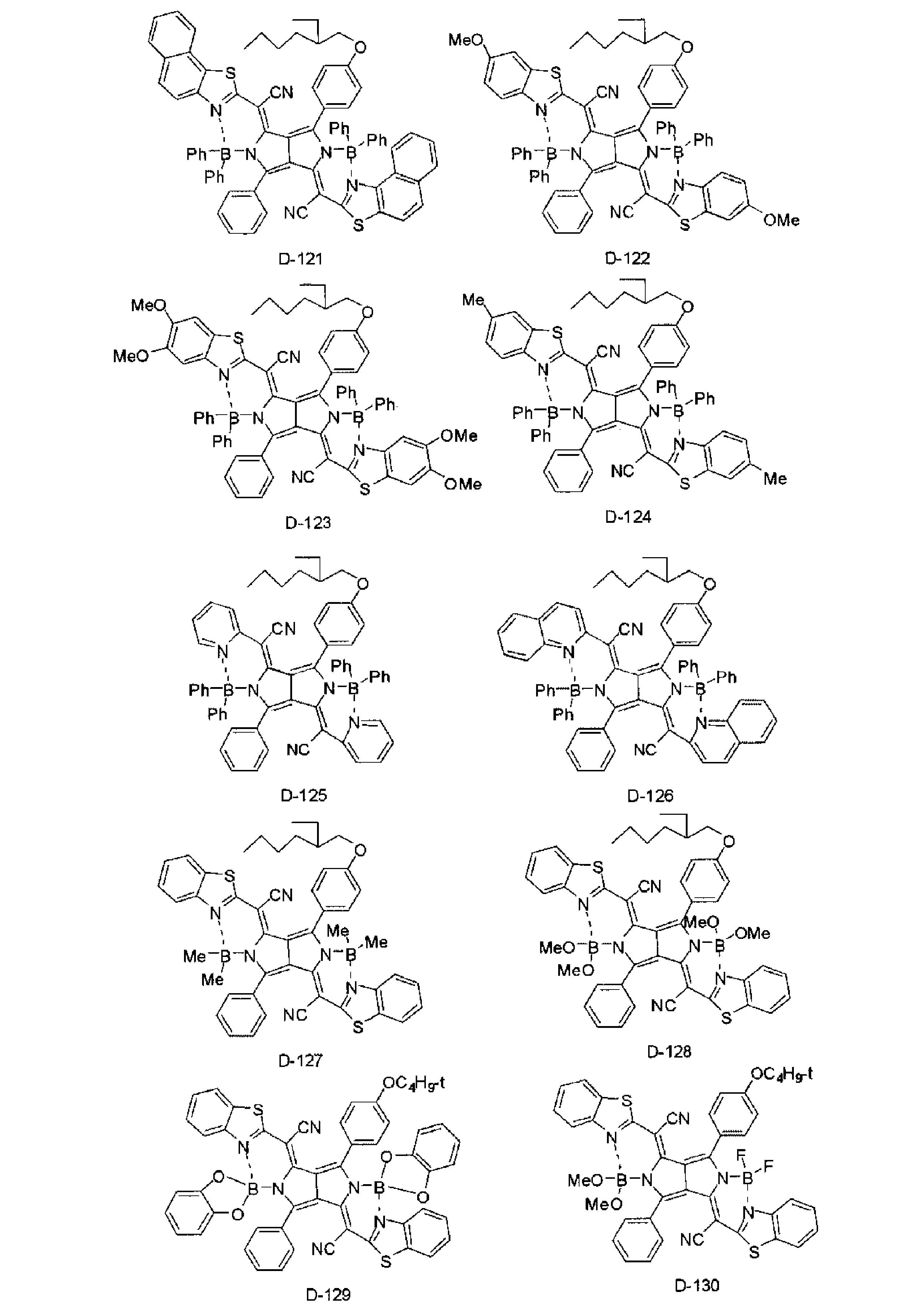
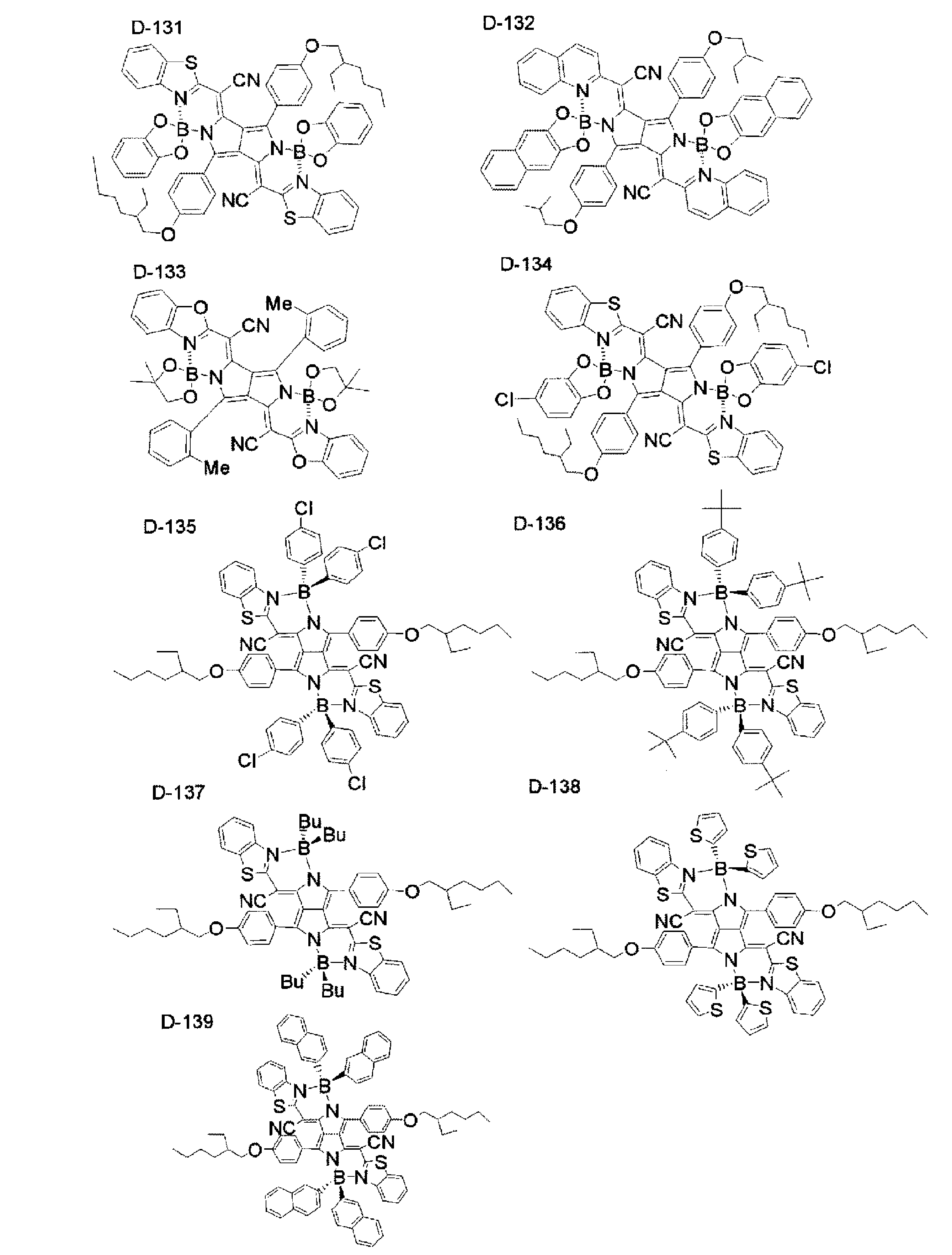

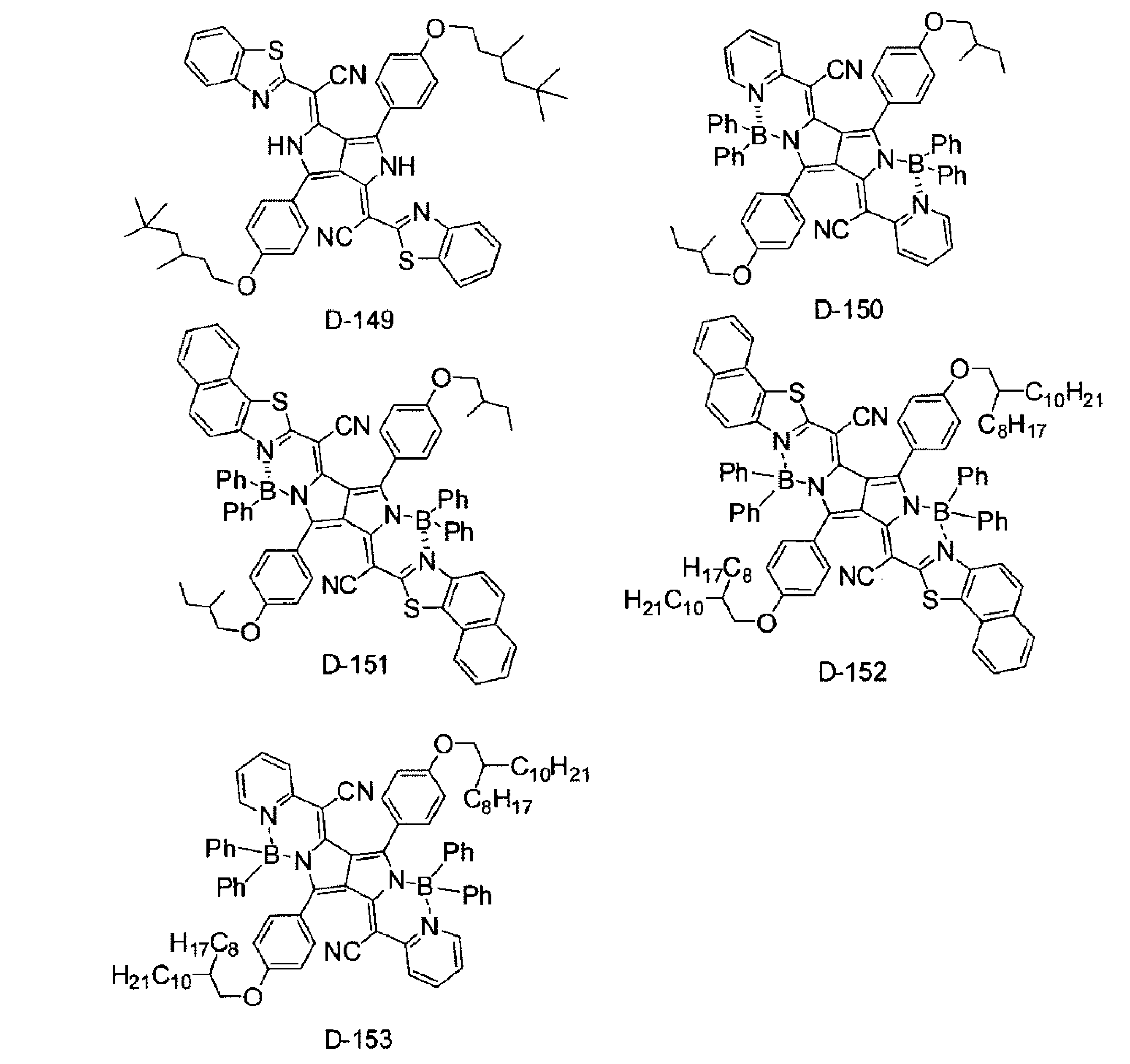
前記一般式(1)で表される化合物の合成法は、特開2011-68731号公報に記載の方法を挙げることができる。
前記一般式(1)で表される化合物の含有量は、必要に応じて調節することができるが、前記近赤外線吸収層中に0.01~50質量%含有させることが好ましく、0.1~30質量%含有させることがより好ましい。この範囲内とすることで近赤外吸収能を付与することができ、同時に不可視性を付与することができる。
前記一般式(1)で表される化合物は、微粒子分散状態で使用することが望ましい。微粒子分散状態で用いることで、化合物の耐久性が向上し、極大吸収波長が長波長化するメリットがある。
前記一般式(1)で表される化合物は、数平均粒径が5~500nmのものが好ましく、10~200nmのものがより好ましく、10~100nmのものが特に好ましい。微粒子の数平均粒径が5nm以上であれば、粒子の表面エネルギーが小さくなるため凝集しにくくなり、微粒子分散が容易になると共に、分散状態を安定に保つのが容易になるため好ましい。また、微粒子の数平均粒径が200nm以下であれば、粒子散乱の影響が少なくなり、吸収スペクトルがシャープになるため好ましい。
前記一般式(1)で表される化合物は、数平均粒径が5~500nmのものが好ましく、10~200nmのものがより好ましく、10~100nmのものが特に好ましい。微粒子の数平均粒径が5nm以上であれば、粒子の表面エネルギーが小さくなるため凝集しにくくなり、微粒子分散が容易になると共に、分散状態を安定に保つのが容易になるため好ましい。また、微粒子の数平均粒径が200nm以下であれば、粒子散乱の影響が少なくなり、吸収スペクトルがシャープになるため好ましい。
前記一般式(1)で表される化合物の微粒子分散物は、例えば、株式会社技術情報協会発行の「顔料分散技術-表面処理と分散剤の使い方および分散性評価-」、株式会社朝倉書店発行の「顔料の事典」、株式会社技術情報協会発行の「最新『顔料分散』実務ノウハウ・事例集」に記載されている方法を用いて製造することができる。微粒子分散物にするためには、通常の分散機を用いることができる。分散機として、ボールミル、振動ボールミル、遊星ボールミル、サンドミル、コロイドミル、ジェットミル及びローラミルを使用することができる。分散機については、例えば、特開昭52-92716号公報及び国際公開第88/074794号パンフレットに記載されている。縦型又は横型の媒体分散機が好ましい。
(分散剤、分散媒)
前記一般式(1)で表される化合物の微粒子分散物の分散安定性を向上させる目的で、分散剤を添加することが望ましい。分散剤として、水酸基含有カルボン酸エステル、長鎖ポリアミノアマイドと高分子量酸エステルの塩、高分子量ポリカルボン酸の塩、長鎖ポリアミノアマイドと極性酸エステルとの塩、高分子量不飽和エステル、高分子共重合物、変性ポリウレタン、変性ポリアクリレート、ポリエーテルエステル型アニオン系活性剤、ナフタレンスルホン酸ホルマリン縮合物塩、芳香族スルホン酸ホルマリン縮合物、ポリオキシエチレンアルキルリン酸エステル、ポリオキシエチレンノニルフェニルエーテル、ステアリルアミンアセテートなどを用いることができる。
前記一般式(1)で表される化合物の微粒子分散物の分散安定性を向上させる目的で、分散剤を添加することが望ましい。分散剤として、水酸基含有カルボン酸エステル、長鎖ポリアミノアマイドと高分子量酸エステルの塩、高分子量ポリカルボン酸の塩、長鎖ポリアミノアマイドと極性酸エステルとの塩、高分子量不飽和エステル、高分子共重合物、変性ポリウレタン、変性ポリアクリレート、ポリエーテルエステル型アニオン系活性剤、ナフタレンスルホン酸ホルマリン縮合物塩、芳香族スルホン酸ホルマリン縮合物、ポリオキシエチレンアルキルリン酸エステル、ポリオキシエチレンノニルフェニルエーテル、ステアリルアミンアセテートなどを用いることができる。
分散剤の具体例としては、例えば、以下のものを挙げることができる。
・オルガノシロキサンポリマー:KP341(商品名、信越化学工業(株)社製)、
・(メタ)アクリル酸系(共)重合体:ポリフローNo.75、No.90、No.95(商品名、共栄社油脂化学工業(株)社製)
・カチオン系界面活性剤:W001(商品名、裕商(株)社製)、
・ノニオン系界面活性剤(ポリオキシエチレンラウリルエーテル、ポリオキシエチレンステアリルエーテル、ポリオキシエチレンオレイルエーテル、ポリオキシエチレンオクチルフェニルエーテル、ポリオキシエチレンノニルフェニルエーテル、ポリエチレングリコールジラウレート、ポリエチレングリコールジステアレート、ソルビタン脂肪酸エステル等):W004、W005、W017(商品名、裕商(株)社製)
・高分子分散剤:EFKA-46、EFKA-47、EFKA-47EA、EFKAポリマー100、EFKAポリマー400、EFKAポリマー401、EFKAポリマー450(以上、商品名、森下産業(株)製)、ディスパースエイド6、ディスパースエイド8、ディスパースエイド15、ディスパースエイド9100(商品名、サンノプコ(株)社製)等
・その他:ソルスパース3000、5000、9000、12000、13240、13940、17000、24000、26000、28000、32000、39000、71000、55000などの各種ソルスパース分散剤(商品名、ルーブリゾール(株)社製);アデカプルロニックL31、F38、L42、L44、L61、L64、F68、L72、P95、F77、P84、F87、P94、L101、P103、F108、L121、P-123(商品名、旭電化(株)社製)、BYK168(商品名、ビックケミー(株)社製)
・オルガノシロキサンポリマー:KP341(商品名、信越化学工業(株)社製)、
・(メタ)アクリル酸系(共)重合体:ポリフローNo.75、No.90、No.95(商品名、共栄社油脂化学工業(株)社製)
・カチオン系界面活性剤:W001(商品名、裕商(株)社製)、
・ノニオン系界面活性剤(ポリオキシエチレンラウリルエーテル、ポリオキシエチレンステアリルエーテル、ポリオキシエチレンオレイルエーテル、ポリオキシエチレンオクチルフェニルエーテル、ポリオキシエチレンノニルフェニルエーテル、ポリエチレングリコールジラウレート、ポリエチレングリコールジステアレート、ソルビタン脂肪酸エステル等):W004、W005、W017(商品名、裕商(株)社製)
・高分子分散剤:EFKA-46、EFKA-47、EFKA-47EA、EFKAポリマー100、EFKAポリマー400、EFKAポリマー401、EFKAポリマー450(以上、商品名、森下産業(株)製)、ディスパースエイド6、ディスパースエイド8、ディスパースエイド15、ディスパースエイド9100(商品名、サンノプコ(株)社製)等
・その他:ソルスパース3000、5000、9000、12000、13240、13940、17000、24000、26000、28000、32000、39000、71000、55000などの各種ソルスパース分散剤(商品名、ルーブリゾール(株)社製);アデカプルロニックL31、F38、L42、L44、L61、L64、F68、L72、P95、F77、P84、F87、P94、L101、P103、F108、L121、P-123(商品名、旭電化(株)社製)、BYK168(商品名、ビックケミー(株)社製)
上記分散剤は、単独で用いてもよくまた2種以上組み合わせて用いてもよい。
微粒子分散物は、分散媒に前記一般式(1)で表される化合物および分散剤を加えて、分散機を用いて、作製することができる。前記一般式(1)で表される化合物に加える分散媒の配合量は、前記一般式(1)で表される化合物を所望の粒径にすることができる量であればよい。分散剤は、前記一般式(1)で表される化合物と分散媒の合計100質量部に対して、1~300質量部程度配合することが好ましい。
前記一般式(1)で表される化合物の分散媒としては特に制限はなく水や公知の有機溶媒を用いることができ、例えば、水、トルエン、キシレン、メチルエチルケトン、メチルイソブチルケトン、アセトン、メチルアルコール、N-プロピルアルコール、1-プロピルアルコール、プロピレングリコールモノメチルエーテル、プロピレングリコールモノメチルエーテルアセテート、シクロヘキサノン、シクロヘキサノール、乳酸エチル、乳酸メチル、カプロラクタム、等の種々のものを用いることができる。その中でも、シクロヘキサノンを用いることが分散剤との相溶性や、塗布後の溶媒の乾燥しやすさの観点から好ましい。
微粒子分散物は、分散媒に前記一般式(1)で表される化合物および分散剤を加えて、分散機を用いて、作製することができる。前記一般式(1)で表される化合物に加える分散媒の配合量は、前記一般式(1)で表される化合物を所望の粒径にすることができる量であればよい。分散剤は、前記一般式(1)で表される化合物と分散媒の合計100質量部に対して、1~300質量部程度配合することが好ましい。
前記一般式(1)で表される化合物の分散媒としては特に制限はなく水や公知の有機溶媒を用いることができ、例えば、水、トルエン、キシレン、メチルエチルケトン、メチルイソブチルケトン、アセトン、メチルアルコール、N-プロピルアルコール、1-プロピルアルコール、プロピレングリコールモノメチルエーテル、プロピレングリコールモノメチルエーテルアセテート、シクロヘキサノン、シクロヘキサノール、乳酸エチル、乳酸メチル、カプロラクタム、等の種々のものを用いることができる。その中でも、シクロヘキサノンを用いることが分散剤との相溶性や、塗布後の溶媒の乾燥しやすさの観点から好ましい。
(近赤外線吸収層の構成)
本発明の赤外線カットフィルムは、前記近赤外線吸収層の膜厚は特に制限はないが、0.1~5μmであることが好ましく、0.2~3μmであることがより好ましい。
本発明の赤外線カットフィルムは、前記近赤外線吸収層の膜厚は特に制限はないが、0.1~5μmであることが好ましく、0.2~3μmであることがより好ましい。
(近赤外線吸収層の形成方法)
本発明の赤外線カットフィルムは、前記近赤外線吸収層の形成方法としては特に制限はないが、塗布により形成されてなることが好ましい。例えば、重合性モノマーや重合性のバインダー樹脂を含有した溶液に前記一般式(1)で表される化合物を分散させた組成物を塗布後、活性エネルギー線、熱など、所定の条件下で乾燥または硬化させて前記近赤外線吸収層を形成することができる。前記近赤外線吸収層は、紫外線硬化型樹脂または熱可塑性樹脂に前記一般式(1)で表される化合物の微粒子が分散されたことがより好ましく、紫外線硬化型樹脂前記一般式(1)で表される化合物の微粒子が分散されたことが特に好ましい。
本発明の赤外線カットフィルムは、前記近赤外線吸収層の形成方法としては特に制限はないが、塗布により形成されてなることが好ましい。例えば、重合性モノマーや重合性のバインダー樹脂を含有した溶液に前記一般式(1)で表される化合物を分散させた組成物を塗布後、活性エネルギー線、熱など、所定の条件下で乾燥または硬化させて前記近赤外線吸収層を形成することができる。前記近赤外線吸収層は、紫外線硬化型樹脂または熱可塑性樹脂に前記一般式(1)で表される化合物の微粒子が分散されたことがより好ましく、紫外線硬化型樹脂前記一般式(1)で表される化合物の微粒子が分散されたことが特に好ましい。
前記熱可塑性樹脂としては特に制限はなく、公知の熱可塑性樹脂を用いることができる。
前記紫外線硬化型樹脂としては特に制限はないが、以下の重合性のバインダー樹脂や重合性モノマーのうち、紫外線により硬化してなる樹脂を挙げることができる。
前記重合性のバインダー樹脂としては、特開2011-068731号公報に記載の樹脂を用いることができる。
前記重合性のバインダー樹脂としては、特開2011-068731号公報に記載の樹脂を用いることができる。
前記重合性モノマーとしては、特に制限は無いが、各種置換基のバリエーションが多く、入手が容易な点で、(メタ)アクリル系モノマー、エポキシ系モノマー、およびオキセタニル系モノマーから選択される1種以上を含有することが好ましい。
重合性モノマーとしては、重合性基を2つ以上有するモノマー(以下、「2官能以上のモノマー」ともいう)が好ましい。重合性モノマーとしては、活性エネルギー線及び/又は熱により重合反応可能であれば特に限定されるものではないが、膜の強度や耐溶剤性等の点から、重合性基を3つ以上有するモノマー(以下、「3官能以上のモノマー」ともいう)がより好ましい。
重合性モノマーとしては、重合性基を2つ以上有するモノマー(以下、「2官能以上のモノマー」ともいう)が好ましい。重合性モノマーとしては、活性エネルギー線及び/又は熱により重合反応可能であれば特に限定されるものではないが、膜の強度や耐溶剤性等の点から、重合性基を3つ以上有するモノマー(以下、「3官能以上のモノマー」ともいう)がより好ましい。
前記重合性基の種類としては、特に制限はないが、上記の通り、アクリロイルオキシ基、メタクリロイルオキシ基、エポキシ基、オキセタニル基が特に好ましい。
重合性モノマーの具体例としては、特開2001-350012号公報の段落番号[0061]~[0065]に記載のエポキシ基含有モノマー、特開2002-371216号公報の段落番号[0016]に記載のアクリレートモノマー及びメタクリレートモノマー、特開2001-220526号公報、特開2001-310937号公報、特開2003-341217号公報の段落番号[0021]~[0084]及び特開2004-91556号公報の段落番号[0022]~[0058]等に記載のオキセタニル基含有モノマー、並びに、シーエムシー出版「反応性モノマーの市場展望」に記載のモノマー等が挙げられる。
重合性モノマーの具体例としては、特開2001-350012号公報の段落番号[0061]~[0065]に記載のエポキシ基含有モノマー、特開2002-371216号公報の段落番号[0016]に記載のアクリレートモノマー及びメタクリレートモノマー、特開2001-220526号公報、特開2001-310937号公報、特開2003-341217号公報の段落番号[0021]~[0084]及び特開2004-91556号公報の段落番号[0022]~[0058]等に記載のオキセタニル基含有モノマー、並びに、シーエムシー出版「反応性モノマーの市場展望」に記載のモノマー等が挙げられる。
エポキシ系モノマーとしては、例えば、ビスフェノールA型エポキシ樹脂、ビスフェノールF型エポキシ樹脂、臭素化ビスフェノールA型エポキシ樹脂、ビスフェノールS型エポキシ樹脂、ジフェニルエーテル型エポキシ樹脂、ハイドロキノン型エポキシ樹脂、ナフタレン型エポキシ樹脂、ビフェニル型エポキシ樹脂、フルオレン型エポキシ樹脂、フェノールノボラック型エポキシ樹脂、オルソクレゾールノボラック型エポキシ樹脂、トリスヒドロキシフェニルメタン型エポキシ樹脂、3官能型エポキシ樹脂、テトラフェニロールエタン型エポキシ樹脂、ジシクロペンタジエンフェノール型エポキシ樹脂、水添ビスフェノールA型エポキシ樹脂、ビスフェノールA含核ポリオール型エポキシ樹脂、ポリプロピレングリコール型エポキシ樹脂、グリシジルエステル型エポキシ樹脂、グリシジルアミン型エポキシ樹脂、グリオキザール型エポキシ樹脂、脂環型エポキシ樹脂、複素環型エポキシ樹脂などを挙げることができる。
また、(メタ)アクリル系モノマーとしては、3官能モノマーとして、例えば、トリメチロールプロパントリアクリレート、トリメチロールプロパンPO(プロピレンオキサイド)変性トリアクリレート、トリメチロールプロパンEO(エチレンオキサイド)変性トリアクリレート、トリメチロールプロパントリメタクリレート、ペンタエリスリトールトリアクリレートなどが挙げられる。また、4官能以上のモノマーとして例えば、ペンタエリスリトールテトラアクリレート、ペンタエリスリトールテトラメタクリレート、ジペンタエリスリトールペンタアクリレート、ジペンタエリスリトールペンタメタクリレート、ジペンタエリスリトールヘキサアクリレート、ジペンタエリスリトールヘキサメタクリレートなどが挙げられる。
また、オキセタニル系モノマーであるオキセタニル基含有モノマーとしては、特開2003-341217号公報の段落番号[0021]~[0084]に記載の化合物を好適に使用できる。更に、特開2004-91556号公報の段落番号[0022]~[0058]に記載の化合物も使用することができる。
また、オキセタニル系モノマーであるオキセタニル基含有モノマーとしては、特開2003-341217号公報の段落番号[0021]~[0084]に記載の化合物を好適に使用できる。更に、特開2004-91556号公報の段落番号[0022]~[0058]に記載の化合物も使用することができる。
<コレステリック液晶相を固定化してなる近赤外線反射層>
本発明の赤外線カットフィルムは、コレステリック液晶相を固定化してなる少なくとも1層の近赤外線反射層を有する。
前記コレステリック液晶相を固定してなる近赤外線反射層の積層数は特に制限はなく、例えば1~10層とすることができ、1~8層が好ましく、1~6層がより好ましく、1200~2000nmの赤外光を反射するための液晶層数を減らし、複合タングステン微粒子が含有する赤外線吸収層を使用してヘイズを下げる観点からは2~4層が特に好ましく、2または3層がより特に好ましく、3層がよりさらに特に好ましい。
本発明の赤外線カットフィルムは、コレステリック液晶相を固定化してなる少なくとも1層の近赤外線反射層を有する。
前記コレステリック液晶相を固定してなる近赤外線反射層の積層数は特に制限はなく、例えば1~10層とすることができ、1~8層が好ましく、1~6層がより好ましく、1200~2000nmの赤外光を反射するための液晶層数を減らし、複合タングステン微粒子が含有する赤外線吸収層を使用してヘイズを下げる観点からは2~4層が特に好ましく、2または3層がより特に好ましく、3層がよりさらに特に好ましい。
本発明の赤外線カットフィルムは、前記近赤外線反射層が、互いに逆方向の円偏光を反射し、反射波長域が750nm~900nmにあって、中心反射波長が互いに実質的に等しい、2層のコレステリック液晶相が固定化された反射層(以下、光反射層X1および光反射層X2という)を含むことが好ましい。
本発明の赤外線カットフィルムは、透明基材(基板ともいう)の一方の表面上のみに近赤外線光反射層を積層した構成であってもよいし、また、基板の双方の表面上に近赤外線光反射層を積層した構成であってもよい。
本発明の赤外線カットフィルムは、基板の一方の表面上のみに近赤外線光反射層を積層した構成の赤外線カットフィルム2組を、別の基板の両面に積層した態様であることも好ましく、その場合は該別の基板が1/2波長の位相差を有する位相差板であることが好ましい。さらにその場合は、形成した赤外線カットフィルムから基板を剥離し、光反射層/ 1/2波長の位相差を有する位相差板/光反射層の構成とすることがより好ましい。
本発明の赤外線カットフィルムは、基板の一方の表面上のみに近赤外線光反射層を積層した構成の赤外線カットフィルム2組を、別の基板の両面に積層した態様であることも好ましく、その場合は該別の基板が1/2波長の位相差を有する位相差板であることが好ましい。さらにその場合は、形成した赤外線カットフィルムから基板を剥離し、光反射層/ 1/2波長の位相差を有する位相差板/光反射層の構成とすることがより好ましい。
本発明の赤外線カットフィルムは、合わせガラス等の他の支持部材に一体化させて用いられてもよい。その際に、光反射層とともに基板も、他の支持部材と一体化してもよいし、基板を剥離して、光反射層を支持部材と一体化してもよい。
これらの態様の中でも、本発明の赤外線カットフィルムは、前記基板の前記光反射層X1側に、他の光反射層X3を介して、前記光反射層X2が設けられていている態様が好ましく、前記基板の前記光反射層X1側に、1層からなる他の光反射層X3を介して、前記光反射層X2が設けられている態様がより好ましく、前記基板、前記光反射層X1、1層からなる前記光反射層X3および前記光反射層X2がこの順に互いに隣接して設けられている態様が特に好ましい。
これらの態様の中でも、本発明の赤外線カットフィルムは、前記基板の前記光反射層X1側に、他の光反射層X3を介して、前記光反射層X2が設けられていている態様が好ましく、前記基板の前記光反射層X1側に、1層からなる他の光反射層X3を介して、前記光反射層X2が設けられている態様がより好ましく、前記基板、前記光反射層X1、1層からなる前記光反射層X3および前記光反射層X2がこの順に互いに隣接して設けられている態様が特に好ましい。
本発明の赤外線カットフィルムは、前記近赤外線反射層のうち少なくとも1層は750nm~1100nmにおける反射率の極大値が40%以上であることが好ましく、45%以上であることがより好ましい。
また、各近赤外線反射層の厚みは、1μm~8μm程度(好ましくは3~7μm程度)である。但し、これらの範囲に限定されるものではない。層の形成に用いる材料(主には液晶材料及びキラル剤)の種類及びその濃度等を調整することで、所望の螺旋ピッチの光反射層を形成することができる。また層の厚みは、塗布量を調整することで所望の範囲とすることができる。
本発明の赤外線カットフィルムは、前記近赤外線反射層は、重合性液晶からなるコレステリック液晶を塗布し、配向させたのちに光重合によって固定化されてなることが好ましい。
-光反射層形成用材料-
本発明の赤外線カットフィルムでは、各光反射層の形成に、硬化性の液晶組成物を用いるのが好ましい。前記液晶組成物の一例として、棒状液晶化合物、光学活性化合物(キラル剤)、及び重合開始剤を少なくとも含有する態様が好ましい。各成分を2種以上含んでいてもよい。例えば、重合性の液晶化合物と非重合性の液晶化合物との併用が可能である。また、低分子液晶化合物と高分子液晶化合物との併用も可能である。更に、配向の均一性や塗布適性、膜強度を向上させるために、水平配向剤、ムラ防止剤、ハジキ防止剤、及び重合性モノマー等の種々の添加剤から選ばれる少なくとも1種を含有していてもよい。また、前記液晶組成物中には、必要に応じて、さらに重合禁止剤、酸化防止剤、紫外線吸収剤、光安定化剤、色材、金属酸化物微粒子等を、光学的性能を低下させない範囲で添加することができる。
本発明の赤外線カットフィルムでは、各光反射層の形成に、硬化性の液晶組成物を用いるのが好ましい。前記液晶組成物の一例として、棒状液晶化合物、光学活性化合物(キラル剤)、及び重合開始剤を少なくとも含有する態様が好ましい。各成分を2種以上含んでいてもよい。例えば、重合性の液晶化合物と非重合性の液晶化合物との併用が可能である。また、低分子液晶化合物と高分子液晶化合物との併用も可能である。更に、配向の均一性や塗布適性、膜強度を向上させるために、水平配向剤、ムラ防止剤、ハジキ防止剤、及び重合性モノマー等の種々の添加剤から選ばれる少なくとも1種を含有していてもよい。また、前記液晶組成物中には、必要に応じて、さらに重合禁止剤、酸化防止剤、紫外線吸収剤、光安定化剤、色材、金属酸化物微粒子等を、光学的性能を低下させない範囲で添加することができる。
(1) 液晶化合物
本発明に使用可能な液晶化合物は、いわゆる棒状液晶化合物であっても、円盤状液晶化合物であってもよく、特に限定されない。その中でも、棒状液晶化合物であることが好ましい。
本発明に使用可能な棒状液晶化合物の例は、棒状ネマチック液晶化合物である。前記棒状ネマチック液晶化合物の例には、アゾメチン類、アゾキシ類、シアノビフェニル類、シアノフェニルエステル類、安息香酸エステル類、シクロヘキサンカルボン酸フェニルエステル類、シアノフェニルシクロヘキサン類、シアノ置換フェニルピリミジン類、アルコキシ置換フェニルピリミジン類、フェニルジオキサン類、トラン類及びアルケニルシクロヘキシルベンゾニトリル類が好ましく用いられる。低分子液晶化合物だけではなく、高分子液晶化合物も用いることができる。
本発明に使用可能な液晶化合物は、いわゆる棒状液晶化合物であっても、円盤状液晶化合物であってもよく、特に限定されない。その中でも、棒状液晶化合物であることが好ましい。
本発明に使用可能な棒状液晶化合物の例は、棒状ネマチック液晶化合物である。前記棒状ネマチック液晶化合物の例には、アゾメチン類、アゾキシ類、シアノビフェニル類、シアノフェニルエステル類、安息香酸エステル類、シクロヘキサンカルボン酸フェニルエステル類、シアノフェニルシクロヘキサン類、シアノ置換フェニルピリミジン類、アルコキシ置換フェニルピリミジン類、フェニルジオキサン類、トラン類及びアルケニルシクロヘキシルベンゾニトリル類が好ましく用いられる。低分子液晶化合物だけではなく、高分子液晶化合物も用いることができる。
本発明に利用する棒状液晶化合物は、重合性であっても非重合性であってもよい。重合性基を有しない棒状液晶化合物については、様々な文献(例えば、Y. Goto et.al., Mol.Cryst. Liq. Cryst. 1995, Vol. 260, pp.23-28)に記載がある。
重合性棒状液晶化合物は、重合性基を棒状液晶化合物に導入することで得られる。重合性基の例には、不飽和重合性基、エポキシ基、及びアジリジニル基が含まれ、不飽和重合性基が好ましく、エチレン性不飽和重合性基が特に好ましい。重合性基は種々の方法で、棒状液晶化合物の分子中に導入できる。重合性棒状液晶化合物が有する重合性基の個数は、好ましくは1~6個、より好ましくは1~3個である。重合性棒状液晶化合物の例は、Makromol.Chem.,190巻、2255頁(1989年)、Advanced Materials 5巻、107頁(1993年)、米国特許第4683327号明細書、同5622648号明細書、同5770107号明細書、国際公開WO95/22586号公報、同95/24455号公報、同97/00600号公報、同98/23580号公報、同98/52905号公報、特開平1-272551号公報、同6-16616号公報、同7-110469号公報、同11-80081号公報、及び特開2001-328973号公報などに記載の化合物が含まれる。2種類以上の重合性棒状液晶化合物を併用してもよい。2種類以上の重合性棒状液晶化合物を併用すると、配向温度を低下させることができる。
重合性棒状液晶化合物は、重合性基を棒状液晶化合物に導入することで得られる。重合性基の例には、不飽和重合性基、エポキシ基、及びアジリジニル基が含まれ、不飽和重合性基が好ましく、エチレン性不飽和重合性基が特に好ましい。重合性基は種々の方法で、棒状液晶化合物の分子中に導入できる。重合性棒状液晶化合物が有する重合性基の個数は、好ましくは1~6個、より好ましくは1~3個である。重合性棒状液晶化合物の例は、Makromol.Chem.,190巻、2255頁(1989年)、Advanced Materials 5巻、107頁(1993年)、米国特許第4683327号明細書、同5622648号明細書、同5770107号明細書、国際公開WO95/22586号公報、同95/24455号公報、同97/00600号公報、同98/23580号公報、同98/52905号公報、特開平1-272551号公報、同6-16616号公報、同7-110469号公報、同11-80081号公報、及び特開2001-328973号公報などに記載の化合物が含まれる。2種類以上の重合性棒状液晶化合物を併用してもよい。2種類以上の重合性棒状液晶化合物を併用すると、配向温度を低下させることができる。
(2) 光学活性化合物(キラル剤)
前記液晶組成物は、コレステリック液晶相を示すものであり、そのためには、光学活性化合物を含有しているのが好ましい。但し、上記棒状液晶化合物が不斉炭素原子を有する分子である場合には、光学活性化合物を添加しなくても、コレステリック液晶相を安定的に形成可能である場合もある。前記光学活性化合物は、公知の種々のキラル剤(例えば、液晶デバイスハンドブック、第3章4-3項、TN、STN用カイラル剤、199頁、日本学術振興会第142委員会編、1989に記載)から選択することができる。光学活性化合物は、一般に不斉炭素原子を含むが、不斉炭素原子を含まない軸性不斉化合物あるいは面性不斉化合物もカイラル剤として用いることができる。軸性不斉化合物または面性不斉化合物の例には、ビナフチル、ヘリセン、パラシクロファンおよびこれらの誘導体が含まれる。光学活性化合物(キラル剤)は、重合性基を有していてもよい。光学活性化合物が重合性基を有するとともに、併用する棒状液晶化合物も重合性基を有する場合は、重合性光学活性化合物と重合性棒状液晶合物との重合反応により、棒状液晶化合物から誘導される繰り返し単位と、光学活性化合物から誘導される繰り返し単位とを有するポリマーを形成することができる。この態様では、重合性光学活性化合物が有する重合性基は、重合性棒状液晶化合物が有する重合性基と、同種の基であることが好ましい。従って、光学活性化合物の重合性基も、不飽和重合性基、エポキシ基又はアジリジニル基であることが好ましく、不飽和重合性基であることがさらに好ましく、エチレン性不飽和重合性基であることが特に好ましい。
また、光学活性化合物は、液晶化合物であってもよい。
前記液晶組成物は、コレステリック液晶相を示すものであり、そのためには、光学活性化合物を含有しているのが好ましい。但し、上記棒状液晶化合物が不斉炭素原子を有する分子である場合には、光学活性化合物を添加しなくても、コレステリック液晶相を安定的に形成可能である場合もある。前記光学活性化合物は、公知の種々のキラル剤(例えば、液晶デバイスハンドブック、第3章4-3項、TN、STN用カイラル剤、199頁、日本学術振興会第142委員会編、1989に記載)から選択することができる。光学活性化合物は、一般に不斉炭素原子を含むが、不斉炭素原子を含まない軸性不斉化合物あるいは面性不斉化合物もカイラル剤として用いることができる。軸性不斉化合物または面性不斉化合物の例には、ビナフチル、ヘリセン、パラシクロファンおよびこれらの誘導体が含まれる。光学活性化合物(キラル剤)は、重合性基を有していてもよい。光学活性化合物が重合性基を有するとともに、併用する棒状液晶化合物も重合性基を有する場合は、重合性光学活性化合物と重合性棒状液晶合物との重合反応により、棒状液晶化合物から誘導される繰り返し単位と、光学活性化合物から誘導される繰り返し単位とを有するポリマーを形成することができる。この態様では、重合性光学活性化合物が有する重合性基は、重合性棒状液晶化合物が有する重合性基と、同種の基であることが好ましい。従って、光学活性化合物の重合性基も、不飽和重合性基、エポキシ基又はアジリジニル基であることが好ましく、不飽和重合性基であることがさらに好ましく、エチレン性不飽和重合性基であることが特に好ましい。
また、光学活性化合物は、液晶化合物であってもよい。
前記液晶組成物中の光学活性化合物は、併用される液晶化合物に対して、1~30モル%であることが好ましい。光学活性化合物の使用量は、より少なくした方が液晶性に影響を及ぼさないことが多いため好まれる。従って、キラル剤として用いられる光学活性化合物は、少量でも所望の螺旋ピッチの捩れ配向を達成可能なように、強い捩り力のある化合物が好ましい。この様な、強い捩れ力を示すキラル剤としては、例えば、特開2003-287623号公報に記載のキラル剤が挙げられ、本発明に好ましく用いることができる。
(3) 重合開始剤
前記光反射層の形成に用いる液晶組成物は、重合性液晶組成物であるのが好ましく、そのためには、重合開始剤を含有しているのが好ましい。本発明では、紫外線照射により硬化反応を進行させるので、使用する重合開始剤は、紫外線照射によって重合反応を開始可能な光重合開始剤であるのが好ましい。光重合開始剤の例には、α-カルボニル化合物(米国特許第2367661号、同2367670号の各明細書記載)、アシロインエーテル(米国特許第2448828号明細書記載)、α-炭化水素置換芳香族アシロイン化合物(米国特許第2722512号明細書記載)、多核キノン化合物(米国特許第3046127号、同2951758号の各明細書記載)、トリアリールイミダゾールダイマーとp-アミノフェニルケトンとの組み合わせ(米国特許第3549367号明細書記載)、アクリジン及びフェナジン化合物(特開昭60-105667号公報、米国特許第4239850号明細書記載)及びオキサジアゾール化合物(米国特許第4212970号明細書記載)等が挙げられる。
前記光反射層の形成に用いる液晶組成物は、重合性液晶組成物であるのが好ましく、そのためには、重合開始剤を含有しているのが好ましい。本発明では、紫外線照射により硬化反応を進行させるので、使用する重合開始剤は、紫外線照射によって重合反応を開始可能な光重合開始剤であるのが好ましい。光重合開始剤の例には、α-カルボニル化合物(米国特許第2367661号、同2367670号の各明細書記載)、アシロインエーテル(米国特許第2448828号明細書記載)、α-炭化水素置換芳香族アシロイン化合物(米国特許第2722512号明細書記載)、多核キノン化合物(米国特許第3046127号、同2951758号の各明細書記載)、トリアリールイミダゾールダイマーとp-アミノフェニルケトンとの組み合わせ(米国特許第3549367号明細書記載)、アクリジン及びフェナジン化合物(特開昭60-105667号公報、米国特許第4239850号明細書記載)及びオキサジアゾール化合物(米国特許第4212970号明細書記載)等が挙げられる。
光重合開始剤の使用量は、液晶組成物(塗布液の場合は固形分)の0.1~20質量%であることが好ましく、1~8質量%であることがさらに好ましい。
(4) 配向制御剤
前記液晶組成物中に、安定的に又は迅速にコレステリック液晶相となるのに寄与する配向制御剤を添加してもよい。配向制御剤の例には、含フッ素(メタ)アクリレート系ポリマー、及び下記一般式(X1)~(X3)で表される化合物が含まれる。これらから選択される2種以上を含有していてもよい。これらの化合物は、層の空気界面において、液晶化合物の分子のチルト角を低減若しくは実質的に水平配向させることができる。尚、本明細書で「水平配向」とは、液晶分子長軸と膜面が平行であることをいうが、厳密に平行であることを要求するものではなく、本明細書では、水平面とのなす傾斜角が20度未満の配向を意味するものとする。液晶化合物が空気界面付近で水平配向する場合、配向欠陥が生じ難いため、可視光領域での透明性が高くなり、また赤外領域での反射率が増大する。一方、液晶化合物の分子が大きなチルト角で配向すると、コレステリック液晶相の螺旋軸が膜面法線からずれるため、反射率が低下したり、フィンガープリントパターンが発生し、ヘイズの増大や回折性を示したりするため好ましくない。
配向制御剤として利用可能な前記含フッ素(メタ)アクリレート系ポリマーの例は、特開2007-272185号公報の[0018]~[0043]等に記載がある。
前記液晶組成物中に、安定的に又は迅速にコレステリック液晶相となるのに寄与する配向制御剤を添加してもよい。配向制御剤の例には、含フッ素(メタ)アクリレート系ポリマー、及び下記一般式(X1)~(X3)で表される化合物が含まれる。これらから選択される2種以上を含有していてもよい。これらの化合物は、層の空気界面において、液晶化合物の分子のチルト角を低減若しくは実質的に水平配向させることができる。尚、本明細書で「水平配向」とは、液晶分子長軸と膜面が平行であることをいうが、厳密に平行であることを要求するものではなく、本明細書では、水平面とのなす傾斜角が20度未満の配向を意味するものとする。液晶化合物が空気界面付近で水平配向する場合、配向欠陥が生じ難いため、可視光領域での透明性が高くなり、また赤外領域での反射率が増大する。一方、液晶化合物の分子が大きなチルト角で配向すると、コレステリック液晶相の螺旋軸が膜面法線からずれるため、反射率が低下したり、フィンガープリントパターンが発生し、ヘイズの増大や回折性を示したりするため好ましくない。
配向制御剤として利用可能な前記含フッ素(メタ)アクリレート系ポリマーの例は、特開2007-272185号公報の[0018]~[0043]等に記載がある。
以下、配向制御剤として利用可能な、下記一般式(X1)~(X3)について、順に説明する。
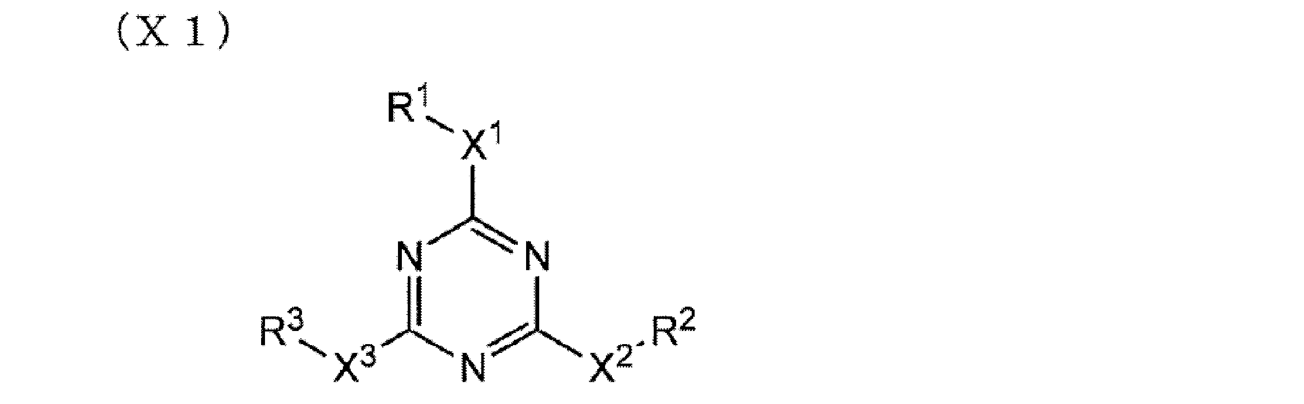
式中、R1、R2及びR3は各々独立して、水素原子又は置換基を表し、X1、X2及びX3は単結合又は二価の連結基を表す。R1~R3で各々表される置換基としては、好ましくは置換もしくは無置換の、アルキル基(中でも、無置換のアルキル基又はフッ素置換アルキル基がより好ましい)、アリール基(中でもフッ素置換アルキル基を有するアリール基が好ましい)、置換もしくは無置換のアミノ基、アルコキシ基、アルキルチオ基、ハロゲン原子である。X1、X2及びX3で各々表される二価の連結基は、アルキレン基、アルケニレン基、二価の芳香族基、二価のヘテロ環残基、-CO-、―NRa-(Raは炭素原子数が1~5のアルキル基又は水素原子)、-O-、-S-、-SO-、-SO2-及びそれらの組み合わせからなる群より選ばれる二価の連結基であることが好ましい。二価の連結基は、アルキレン基、フェニレン基、-CO-、-NRa-、-O-、-S-及び-SO2-からなる群より選ばれる二価の連結基又は該群より選ばれる基を少なくとも二つ組み合わせた二価の連結基であることがより好ましい。アルキレン基の炭素原子数は、1~12であることが好ましい。アルケニレン基の炭素原子数は、2~12であることが好ましい。二価の芳香族基の炭素原子数は、6~10であることが好ましい。

式中、Rは置換基を表し、mは0~5の整数を表す。mが2以上の整数を表す場合、複数個のRは同一でも異なっていてもよい。Rとして好ましい置換基は、R1、R2、及びR3で表される置換基の好ましい範囲として挙げたものと同様である。mは、好ましくは1~3の整数を表し、特に好ましくは2又は3である。

式中、R4、R5、R6、R7、R8及びR9は各々独立して、水素原子又は置換基を表す。R4、R5、R6、R7、R8及びR9でそれぞれ表される置換基は、好ましくは一般式(XI)におけるR1、R2及びR3で表される置換基の好ましいものとして挙げたものと同様である。
本発明において配向制御剤として使用可能な、前記式(X1)~(X3)で表される化合物の例には、特開2005-99248号公報に記載の化合物が含まれる。
なお、本発明では、配向制御剤として、前記一般式(X1)~(X3)で表される化合物の一種を単独で用いてもよいし、二種以上を併用してもよい。
なお、本発明では、配向制御剤として、前記一般式(X1)~(X3)で表される化合物の一種を単独で用いてもよいし、二種以上を併用してもよい。
前記液晶組成物中における、一般式(X1)~(X3)のいずれかで表される化合物の添加量は、液晶化合物の質量の0.01~10質量%が好ましく、0.01~5質量%がより好ましく、0.02~1質量%が特に好ましい。
<金属酸化物粒子>
本発明の赤外線カットフィルムは、長波赤外線を吸収するために、少なくとも1種の金属酸化物粒子を含有していても熱線遮蔽と製造コストのバランスの観点からは好ましい。
前記金属酸化物粒子の材料としては、特に制限はなく、目的に応じて適宜選択することができ、例えば、複合タングステン酸化物、錫ドープ酸化インジウム(以下、「ITO」と略記する。)、錫ドープ酸化アンチモン(以下、「ATO」と略記する。)、酸化亜鉛、酸化チタン、酸化インジウム、酸化錫、酸化アンチモン、ガラスセラミックスなどが挙げられる。これらの中でも、熱線吸収能力に優れ、金属平板粒子と組み合わせることにより幅広い熱線吸収能を有する赤外線カットフィルムが製造できる点で、前記金属微粒子分散物が、下記一般式(I)で表される複合タングステン酸化物であることが好ましい。
MxWOy・・・(I)
(M元素はCs、Na、Rb、K、Tl、In、Ba、Li、Ca、Sr、Fe、およびSnからなる群から選ばれる少なくとも1種、Wはタングステン、Oは酸素で、0.1≦x≦0.5、2.2≦y≦3.0)
上記一般式(I)で示される前記複合タングステン酸化物のうち、特にM元素がCsで表わされるセシウム含有酸化タングステンが、近赤外線吸収能が高いことから好適である。
本発明の赤外線カットフィルムは、長波赤外線を吸収するために、少なくとも1種の金属酸化物粒子を含有していても熱線遮蔽と製造コストのバランスの観点からは好ましい。
前記金属酸化物粒子の材料としては、特に制限はなく、目的に応じて適宜選択することができ、例えば、複合タングステン酸化物、錫ドープ酸化インジウム(以下、「ITO」と略記する。)、錫ドープ酸化アンチモン(以下、「ATO」と略記する。)、酸化亜鉛、酸化チタン、酸化インジウム、酸化錫、酸化アンチモン、ガラスセラミックスなどが挙げられる。これらの中でも、熱線吸収能力に優れ、金属平板粒子と組み合わせることにより幅広い熱線吸収能を有する赤外線カットフィルムが製造できる点で、前記金属微粒子分散物が、下記一般式(I)で表される複合タングステン酸化物であることが好ましい。
MxWOy・・・(I)
(M元素はCs、Na、Rb、K、Tl、In、Ba、Li、Ca、Sr、Fe、およびSnからなる群から選ばれる少なくとも1種、Wはタングステン、Oは酸素で、0.1≦x≦0.5、2.2≦y≦3.0)
上記一般式(I)で示される前記複合タングステン酸化物のうち、特にM元素がCsで表わされるセシウム含有酸化タングステンが、近赤外線吸収能が高いことから好適である。
また、上記一般式(I)において、添加されるM元素の添加量はタングステンの含有量を基準としたx/yの値として、0.001≦x/y≦1.1の関係を満足することが好ましく、特にx/yが0.33付近であることが、好適な近赤外線吸収能を示す点で好ましい。また、x/yが0.33付近であると、六方晶の結晶構造をとりやすく、該結晶構造をとることによって、耐久性の点でも好適である。
また、上記一般式(I)における酸素の含有量は、タングステンの含有量を基準としたz/yの値として、2.2≦z/y≦3.0の関係を満足することが好ましい。より具体的には、Cs0.33WO3、Rb0.33WO3、K0.33WO3、Ba0.33WO3などを挙げることができる。
上記無機近赤外線吸収剤は1種を単独で用いてもよく、又は2種以上を併用することもできる。
また、上記一般式(I)における酸素の含有量は、タングステンの含有量を基準としたz/yの値として、2.2≦z/y≦3.0の関係を満足することが好ましい。より具体的には、Cs0.33WO3、Rb0.33WO3、K0.33WO3、Ba0.33WO3などを挙げることができる。
上記無機近赤外線吸収剤は1種を単独で用いてもよく、又は2種以上を併用することもできる。
本発明の赤外線カットフィルムは、前記複合タングステン酸化物微粒子の平均粒径が5~500nmであることが好ましく、10~100nmであることがより好ましく、20~50nmであることが特に好ましい。
前記複合タングステン酸化物微粒子としては、特開2009-227938号公報に記載のものを好ましく用いることができる。
前記複合タングステン酸化物の製造方法としては、特に限定されるものではなく、公知のいずれの方法も用いることができる。例えば、金属塩や金属アルコキシドを原料に用い、水を含有する反応系において加水分解することにより、所望の酸化物微粒子を得ることができる。
また、水中で加水分解させる方法以外には有機溶媒中や熱可塑性樹脂が溶解した有機溶媒中で無機微粒子を作製してもよい。これらの方法に用いられる溶媒としては、例えばアセトン、2-ブタノン、ジクロロメタン、クロロホルム、トルエン、酢酸エチル、シクロヘキサノン、アニソール等が例として挙げられる。これらは、1種類を単独で使用してもよく、また複数種を混合して使用してもよい。
前記金属酸化物粒子の一次粒子の体積平均粒径としては、可視光透過率を低下させないため、0.1μm以下が好ましい。
前記金属酸化物粒子の形状としては、特に制限はなく、目的に応じて適宜選択することができ、例えば、球状、針状、板状などが挙げられる。
前記金属酸化物粒子の形状としては、特に制限はなく、目的に応じて適宜選択することができ、例えば、球状、針状、板状などが挙げられる。
前記金属酸化物粒子の前記金属酸化物粒子含有層における含有量としては、特に制限はなく、目的に応じて適宜選択することができるが、0.1g/m2~20g/m2が好ましく、0.5g/m2~10g/m2がより好ましく、1.0g/m2~4.0g/m2がより好ましい。
前記含有量が、0.1g/m2未満であると、肌に感じる日射量が上昇することがあり、20g/m2を超えると、可視光透過率が悪化することがある。一方、前記含有量が、1.0g/m2~4.0g/m2であると、上記2点を回避できる点で有利である。
なお、前記金属酸化物粒子の前記金属酸化物粒子含有層における含有量は、例えば、前記熱線遮蔽層の超箔切片TEM像及び表面SEM像の観察から、一定面積における金属酸化物粒子の個数及び平均粒子径を測定し、該個数及び平均粒子径と、金属酸化物粒子の比重とに基づいて算出した質量(g)を、前記一定面積(m2)で除することにより算出することができる。また、前記金属酸化物粒子含有層の一定面積における金属酸化物微粒子をメタノールに溶出させ、蛍光X線測定により測定した金属酸化物微粒子の質量(g)を、前記一定面積(m2)で除することにより算出することもできる。
前記含有量が、0.1g/m2未満であると、肌に感じる日射量が上昇することがあり、20g/m2を超えると、可視光透過率が悪化することがある。一方、前記含有量が、1.0g/m2~4.0g/m2であると、上記2点を回避できる点で有利である。
なお、前記金属酸化物粒子の前記金属酸化物粒子含有層における含有量は、例えば、前記熱線遮蔽層の超箔切片TEM像及び表面SEM像の観察から、一定面積における金属酸化物粒子の個数及び平均粒子径を測定し、該個数及び平均粒子径と、金属酸化物粒子の比重とに基づいて算出した質量(g)を、前記一定面積(m2)で除することにより算出することができる。また、前記金属酸化物粒子含有層の一定面積における金属酸化物微粒子をメタノールに溶出させ、蛍光X線測定により測定した金属酸化物微粒子の質量(g)を、前記一定面積(m2)で除することにより算出することもできる。
<ジインモニウム色素>
本発明の赤外線カットフィルムは、さらにジインモニウム色素を含むことも好ましい。ジインモニウム色素は、800nm~1100nmの吸収波長帯において、長波長側の近赤外線を吸収することができる。ジインモニウム色素としては、特開2005-054031号公報などに記載のものを好ましく用いることができる。
ジインモニウム色素の添加する層としては特に制限はないが、後述の易接着層に添加することが好ましい。
本発明の赤外線カットフィルムは、さらにジインモニウム色素を含むことも好ましい。ジインモニウム色素は、800nm~1100nmの吸収波長帯において、長波長側の近赤外線を吸収することができる。ジインモニウム色素としては、特開2005-054031号公報などに記載のものを好ましく用いることができる。
ジインモニウム色素の添加する層としては特に制限はないが、後述の易接着層に添加することが好ましい。
<その他の層・成分>
本発明の赤外線カットフィルムは、易接着層、ハードコート層、紫外線吸収層、粘着層および表面保護層のうち少なくとも1つをさらに有することが好ましい。
本発明の赤外線カットフィルムは、易接着層、ハードコート層、紫外線吸収層、粘着層および表面保護層のうち少なくとも1つをさらに有することが好ましい。
-易接着層-
本発明の赤外線カットフィルムは、一方又は双方の最外層として、易接着層を有していてもよい。易接着層は、例えば、合わせガラス用中間膜との接着性を改善する機能を有する。より具体的には、易接着層は、コレステリック液晶相の光反射層及び/又は基板と、合わせガラス用中間膜との接着性を改善する機能を有する。易接着層の形成に利用可能な材料としては、ポリビニルブチラール(PVB)樹脂が挙げられる。ポリビニルブチラール樹脂は、ポリビニルアルコール(PVA)とブチルアルデヒドを酸触媒で反応させて生成するポリビニルアセタールの一種であり、下記構造の繰り返し単位を有する樹脂である。
本発明の赤外線カットフィルムは、一方又は双方の最外層として、易接着層を有していてもよい。易接着層は、例えば、合わせガラス用中間膜との接着性を改善する機能を有する。より具体的には、易接着層は、コレステリック液晶相の光反射層及び/又は基板と、合わせガラス用中間膜との接着性を改善する機能を有する。易接着層の形成に利用可能な材料としては、ポリビニルブチラール(PVB)樹脂が挙げられる。ポリビニルブチラール樹脂は、ポリビニルアルコール(PVA)とブチルアルデヒドを酸触媒で反応させて生成するポリビニルアセタールの一種であり、下記構造の繰り返し単位を有する樹脂である。

前記易接着層は、塗布により形成するのが好ましい。例えば、コレステリック液晶相の光反射層の表面及び/又は基板の裏面(光反射層が形成されていない側の面)に、塗布により形成してもよい。より具体的には、ポリビニルブチラール樹脂の1種を有機溶媒に溶解して塗布液を調製し、該塗布液を、コレステリック液晶相の光反射層の表面及び/又は基板の裏面に塗布して、所望により加熱して乾燥し、易接着層を形成することができる。塗布液の調製に用いる溶媒としては、例えば、メトキシプロピルアセテート(PGMEA)、メチルエチルケトン(MEK)、イソプロパノール(IPA)等を用いることができる。塗布方法としては、従来公知の種々の方法を利用することができる。乾燥時の温度は、塗布液の調製に用いた材料によって好ましい範囲が異なるが、一般的には、140~160℃程度であるのが好ましい。乾燥時間についても特に制限はないが、一般的には、5~10分程度である。
また、前記易接着層は、いわゆるアンダーコート層といわれる、アクリル樹脂、スチレン/アクリル樹脂、ウレタン樹脂、ポリエステル樹脂等からなる層であってもよい。これらの材料からなる易接着層も塗布により形成することができる。なお、市販されているポリマーフィルムの中には、アンダーコート層が付与されているものもあるので、それらの市販品を基板として利用することもできる。
なお、易接着層の厚みは、0.1~2.0μmが好ましい。
なお、易接着層の厚みは、0.1~2.0μmが好ましい。
-下塗り層-
本発明の赤外線カットフィルムは、コレステリック液晶相の光反射層と基板との間に下塗り層を有していてもよい。コレステリック液晶相の光反射層と基板との密着力が弱いと、コレステリック液晶相の光反射層を積層して製造する際の工程で剥離故障が起き易くなったり、赤外線カットフィルムとして合わせガラスにした際の強度(耐衝撃性)低下を引き起こす。よって、下塗り層として、コレステリック液晶層と基板との接着性を向上させることができる層を利用することができる。一方で、基板、又は基板と下塗り層とを剥離して、中間膜シート等の部材と光反射層を一体化する場合は、基板と下塗り層、又は下塗り層とコレステリック液晶相の光反射層との界面には、剥離可能な程度の接着性の弱さが必要である。後工程で積層中間膜シートにすることを考えると、下塗り層と基板との界面で剥離する方が好ましい。
下塗り層の形成に利用可能な材料の例には、アクリル酸エステル共重合体、ポリ塩化ビニリデン、スチレンブタジエンゴム(SBR)、水性ポリエステル等が含まれる。また、下塗り層の表面を中間膜と接着する態様では、下塗り層と中間膜との接着性が良好であるのが好ましく、その観点では、下塗り層は、ポリビニルブチラール樹脂も、前記材料とともに含有しているのが好ましい。また、下塗り層は、上記したように密着力を適度に調節する必要があるので、グルタルアルデヒド、2,3-ジヒドロキシ-1,4-ジオキサン等のジアルデヒド類またはホウ酸等の硬膜剤を適宜用いて硬膜させることが好ましい。硬膜剤の添加量は、下塗り層の乾燥質量の0.2~3.0質量%が好ましい。
下塗り層の厚みは、0.05~0.5μmが好ましい。
本発明の赤外線カットフィルムは、コレステリック液晶相の光反射層と基板との間に下塗り層を有していてもよい。コレステリック液晶相の光反射層と基板との密着力が弱いと、コレステリック液晶相の光反射層を積層して製造する際の工程で剥離故障が起き易くなったり、赤外線カットフィルムとして合わせガラスにした際の強度(耐衝撃性)低下を引き起こす。よって、下塗り層として、コレステリック液晶層と基板との接着性を向上させることができる層を利用することができる。一方で、基板、又は基板と下塗り層とを剥離して、中間膜シート等の部材と光反射層を一体化する場合は、基板と下塗り層、又は下塗り層とコレステリック液晶相の光反射層との界面には、剥離可能な程度の接着性の弱さが必要である。後工程で積層中間膜シートにすることを考えると、下塗り層と基板との界面で剥離する方が好ましい。
下塗り層の形成に利用可能な材料の例には、アクリル酸エステル共重合体、ポリ塩化ビニリデン、スチレンブタジエンゴム(SBR)、水性ポリエステル等が含まれる。また、下塗り層の表面を中間膜と接着する態様では、下塗り層と中間膜との接着性が良好であるのが好ましく、その観点では、下塗り層は、ポリビニルブチラール樹脂も、前記材料とともに含有しているのが好ましい。また、下塗り層は、上記したように密着力を適度に調節する必要があるので、グルタルアルデヒド、2,3-ジヒドロキシ-1,4-ジオキサン等のジアルデヒド類またはホウ酸等の硬膜剤を適宜用いて硬膜させることが好ましい。硬膜剤の添加量は、下塗り層の乾燥質量の0.2~3.0質量%が好ましい。
下塗り層の厚みは、0.05~0.5μmが好ましい。
-配向層-
本発明の赤外線カットフィルムは、コレステリック液晶相の光反射層と基板との間に配向層を有していてもよい。配向層は、コレステリック液晶層中の液晶化合物の配向方向をより精密に規定する機能を有する。配向層は、有機化合物(好ましくはポリマー)のラビング処理、無機化合物の斜方蒸着、マイクログルーブを有する層の形成等の手段で設けることができる。さらには、電場の付与、磁場の付与、或いは光照射により配向機能が生じる配向層も知られている。配向層は、ポリマーの膜の表面に、ラビング処理により形成するのが好ましい。
配向層は、コレステリック液晶相の光反射層と隣接する必要があるので、コレステリック液晶相の光反射層と基板又は下塗り層との間に設けるのが好ましい。但し、下塗り層が配向層の機能を有していてもよい。また、光反射層の間に配向層を有していてもよい。
本発明の赤外線カットフィルムは、コレステリック液晶相の光反射層と基板との間に配向層を有していてもよい。配向層は、コレステリック液晶層中の液晶化合物の配向方向をより精密に規定する機能を有する。配向層は、有機化合物(好ましくはポリマー)のラビング処理、無機化合物の斜方蒸着、マイクログルーブを有する層の形成等の手段で設けることができる。さらには、電場の付与、磁場の付与、或いは光照射により配向機能が生じる配向層も知られている。配向層は、ポリマーの膜の表面に、ラビング処理により形成するのが好ましい。
配向層は、コレステリック液晶相の光反射層と隣接する必要があるので、コレステリック液晶相の光反射層と基板又は下塗り層との間に設けるのが好ましい。但し、下塗り層が配向層の機能を有していてもよい。また、光反射層の間に配向層を有していてもよい。
配向層は、隣接する、コレステリック液晶相の光反射層、及び下塗り層又は基板のいずれに対しても、ある程度の密着力を有することが好ましい。ただし、後述する本発明の実施態様の一例である、コレステリック液晶相の光反射層から基板を剥離しながら1/2波長の位相差を有する位相差板と貼り合わせて赤外線カットフィルムを作製したり、積層中間膜シートを作製する場合には、コレステリック液晶相の光反射層/配向層/下塗り層/基板のいずれかの界面にて、剥離ができる程度の弱さが必要である。剥離する界面は、どの界面でも構わないが、後工程で積層中間膜シートにすることを考えると、配向層と下塗り層との界面で剥離する方が好ましい。
配向層として用いられる材料としては、有機化合物のポリマーが好ましく、それ自体が架橋可能なポリマーか、或いは架橋剤により架橋されるポリマーがよく用いられる。当然、双方の機能を有するポリマーも用いられる。ポリマーの例としては、ポリメチルメタクリレ-ト、アクリル酸/メタクリル酸共重合体、スチレン/マレインイミド共重合体、ポリビニルアルコ-ル及び変性ポリビニルアルコ-ル、ポリ(N-メチロ-ルアクリルアミド)、スチレン/ビニルトルエン共重合体、クロロスルホン化ポリエチレン、ニトロセルロース、ポリ塩化ビニル、塩素化ポリオレフィン、ポリエステル、ポリイミド、酢酸ビニル/塩化ビニル共重合体、エチレン/酢酸ビニル共重合体、カルボキシメチルセルロ-ス、ゼラチン、ポリエチレン、ポリプロピレン及びポリカーボネート等のポリマー及びシランカップリング剤等の化合物を挙げることができる。好ましいポリマーの例としては、ポリ(N-メチロ-ルアクリルアミド)、カルボキシメチルセルロ-ス、ゼラチン、ポリビルアルコール及び変性ポリビニルアルコール等の水溶性ポリマーであり、さらにゼラチン、ポリビルアルコール及び変性ポリビニルアルコールが好ましく、特にポリビルアルコール及び変性ポリビニルアルコールを挙げることができる。また、配向層の表面を中間膜と接着する態様では、配向層と中間膜との接着性が良好であるのが好ましく、その観点では、配向層は、ポリビニルブチラール樹脂も、前記材料とともに含有しているのが好ましい。
前記配向層の厚みは、0.1~2.0μmが好ましい。
前記配向層の厚みは、0.1~2.0μmが好ましい。
-ハードコート層-
耐擦傷性を付加するために、ハードコート性を有するハードコート層を含むことも好適である。ハードコート層には金属酸化物粒子を含むことができる。
前記ハードコート層としては、特に制限はなく、目的に応じて適宜その種類も形成方法も選択することができ、例えば、アクリル系樹脂、シリコーン系樹脂、メラミン系樹脂、ウレタン系樹脂、アルキド系樹脂、フッ素系樹脂等の熱硬化型又は光硬化型樹脂などが挙げられる。前記ハードコート層の厚みとしては、特に制限はなく、目的に応じて適宜選択することができるが、1μm~50μmが好ましい。前記ハードコート層上に更に反射防止層及び/又は防眩層を形成すると、耐擦傷性に加え、反射防止性及び/又は防眩性を有する機能性フィルムが得られ好適である。また、前記ハードコート層に前記金属酸化物粒子を含有してもよい。
耐擦傷性を付加するために、ハードコート性を有するハードコート層を含むことも好適である。ハードコート層には金属酸化物粒子を含むことができる。
前記ハードコート層としては、特に制限はなく、目的に応じて適宜その種類も形成方法も選択することができ、例えば、アクリル系樹脂、シリコーン系樹脂、メラミン系樹脂、ウレタン系樹脂、アルキド系樹脂、フッ素系樹脂等の熱硬化型又は光硬化型樹脂などが挙げられる。前記ハードコート層の厚みとしては、特に制限はなく、目的に応じて適宜選択することができるが、1μm~50μmが好ましい。前記ハードコート層上に更に反射防止層及び/又は防眩層を形成すると、耐擦傷性に加え、反射防止性及び/又は防眩性を有する機能性フィルムが得られ好適である。また、前記ハードコート層に前記金属酸化物粒子を含有してもよい。
-紫外線吸収剤-
本発明の赤外線カットフィルムは、紫外線吸収剤が含まれている層を有することが好ましい。
前記紫外線吸収剤を含有する層は、目的に応じて適宜選択することができるが、紫外線吸収剤の種類によっては、液晶の配向に影響を与えるため、光反射層以外の部材(層、基板等)に添加するのが好ましい。本発明の実施態様は、種々の形態をとり得るが、光反射層と比較して、より先に光が入射する部材中に添加することが好ましい。例えば、屋外側に配置されるガラス板と、コレステリック液晶相の光反射層との間に配置される層中に添加するのが好ましい。或いは、屋外側に配置されるガラス板に接着させられる中間膜や屋外側に配置されるガラス板そのものに含有させることも好ましい。
紫外線吸収剤として使用可能な化合物の例としては、ベンゾトリアゾール系、ベンゾジチオール系、クマリン系、ベンゾフェノン系、サリチル酸エステル系、シアノアクリレート系等の紫外線吸収剤;酸化チタン、酸化亜鉛などが挙げられる。特に好ましい紫外線吸収剤の例には、Tinuvin326,328,479(いずれもチバ・ジャパン社製)等が含まれる。また、紫外線吸収剤の種類、配合量は特に制限はなく、目的に応じて適宜選択することができる。特に、紫外線吸収剤を含有する部材が、波長380nm以下の紫外線の透過率を0.1%以下にする作用があると、光反射層の劣化を顕著に軽減でき、紫外線による黄変を格段に軽減できるので好ましい。よって、この特性を満足する様に、紫外線吸収剤の種類及び配合量を決定するのが好ましい。
本発明の赤外線カットフィルムは、紫外線吸収剤が含まれている層を有することが好ましい。
前記紫外線吸収剤を含有する層は、目的に応じて適宜選択することができるが、紫外線吸収剤の種類によっては、液晶の配向に影響を与えるため、光反射層以外の部材(層、基板等)に添加するのが好ましい。本発明の実施態様は、種々の形態をとり得るが、光反射層と比較して、より先に光が入射する部材中に添加することが好ましい。例えば、屋外側に配置されるガラス板と、コレステリック液晶相の光反射層との間に配置される層中に添加するのが好ましい。或いは、屋外側に配置されるガラス板に接着させられる中間膜や屋外側に配置されるガラス板そのものに含有させることも好ましい。
紫外線吸収剤として使用可能な化合物の例としては、ベンゾトリアゾール系、ベンゾジチオール系、クマリン系、ベンゾフェノン系、サリチル酸エステル系、シアノアクリレート系等の紫外線吸収剤;酸化チタン、酸化亜鉛などが挙げられる。特に好ましい紫外線吸収剤の例には、Tinuvin326,328,479(いずれもチバ・ジャパン社製)等が含まれる。また、紫外線吸収剤の種類、配合量は特に制限はなく、目的に応じて適宜選択することができる。特に、紫外線吸収剤を含有する部材が、波長380nm以下の紫外線の透過率を0.1%以下にする作用があると、光反射層の劣化を顕著に軽減でき、紫外線による黄変を格段に軽減できるので好ましい。よって、この特性を満足する様に、紫外線吸収剤の種類及び配合量を決定するのが好ましい。
-粘着剤層-
本発明の赤外線カットフィルムは、粘着剤層(以下、粘着層ともいう)を有することが好ましい。前記粘着層は、紫外線吸収剤を含むことができる。
前記粘着層の形成に利用可能な材料としては、特に制限はなく、目的に応じて適宜選択することができ、例えば、ポリビニルブチラール(PVB)樹脂、アクリル樹脂、スチレン/アクリル樹脂、ウレタン樹脂、ポリエステル樹脂、シリコーン樹脂などが挙げられる。これらは、1種単独で使用してもよいし、2種以上を併用してもよい。これらの材料からなる粘着層は、塗布により形成することができる。
さらに、前記粘着層には帯電防止剤、滑剤、ブロッキング防止剤などを添加してもよい。
前記粘着層の厚みとしては、0.1μm~10μmが好ましい。
本発明の赤外線カットフィルムは、粘着剤層(以下、粘着層ともいう)を有することが好ましい。前記粘着層は、紫外線吸収剤を含むことができる。
前記粘着層の形成に利用可能な材料としては、特に制限はなく、目的に応じて適宜選択することができ、例えば、ポリビニルブチラール(PVB)樹脂、アクリル樹脂、スチレン/アクリル樹脂、ウレタン樹脂、ポリエステル樹脂、シリコーン樹脂などが挙げられる。これらは、1種単独で使用してもよいし、2種以上を併用してもよい。これらの材料からなる粘着層は、塗布により形成することができる。
さらに、前記粘着層には帯電防止剤、滑剤、ブロッキング防止剤などを添加してもよい。
前記粘着層の厚みとしては、0.1μm~10μmが好ましい。
<赤外線カットフィルムの製造方法>
本発明の赤外線カットフィルムを製造する方法としては、特に制限はなく、目的に応じて適宜選択することができ、例えば、前記支持体などの下層の表面上に、近赤外線反射層や近赤外線吸収層用の塗布液を、ディップコーター、ダイコーター、スリットコーター、バーコーター、グラビアコーター等により塗布する方法、LB膜法、自己組織化法、スプレー塗布などの方法で面配向させる方法が挙げられる。さらにその中でもバーコーターにより塗布する方法が好ましい。
本発明の赤外線カットフィルムを製造する方法としては、特に制限はなく、目的に応じて適宜選択することができ、例えば、前記支持体などの下層の表面上に、近赤外線反射層や近赤外線吸収層用の塗布液を、ディップコーター、ダイコーター、スリットコーター、バーコーター、グラビアコーター等により塗布する方法、LB膜法、自己組織化法、スプレー塗布などの方法で面配向させる方法が挙げられる。さらにその中でもバーコーターにより塗布する方法が好ましい。
前記近赤外線反射層や近赤外線吸収層を塗布により形成する場合、塗布液には前記色素や、前記ポリマーの他、溶媒や界面活性剤などのその他の添加剤を添加してもよい。
前記溶媒としては、特に制限はなく水や公知の有機溶媒を用いることができ、例えば、水、トルエン、キシレン、メチルエチルケトン、メチルイソブチルケトン、アセトン、メチルアルコール、N-プロピルアルコール、1-プロピルアルコール、プロピレングリコールモノメチルエーテル、プロピレングリコールモノメチルエーテルアセテート、シクロヘキサノン、シクロヘキサノール、乳酸エチル、乳酸メチル、カプロラクタム、等の種々のものを用いることができる。本発明では、環境影響の観点と、塗布コスト低減の点から水性の溶媒を用いることが好ましい。
前記溶媒は、1種単独で用いる以外に2種以上を組合せて用いてもよい。
前記溶媒は、1種単独で用いる以外に2種以上を組合せて用いてもよい。
前記近赤外線反射層や近赤外線吸収層を塗布により形成する場合、前記塗布液を塗布後、公知の方法で乾燥して、固化し、前記近赤外線反射層や近赤外線吸収層を形成することが好ましい。乾燥方法としては、加熱による乾燥が好ましい。
前記近赤外線反射層の製造方法の一例は、
(1) 基板等の表面に、硬化性の液晶組成物を塗布して、コレステリック液晶相の状態にすること、
(2) 前記硬化性の液晶組成物に紫外線を照射して硬化反応を進行させ、コレステリック液晶相を固定して光反射層を形成すること、
を少なくとも含む製造方法である。
(1)及び(2)の工程を、基板の一方の表面上で2回繰り返すことで図1に示す構成と同様の構成の熱線カットフィルムを作製することができる。
なお、コレステリック液晶相の旋回の方向は、用いる液晶の種類又は添加されるキラル剤の種類によって調整でき、螺旋ピッチ(すなわち、中心反射波長)は、これらの材料の濃度によって任意に調整できる。また、光反射層の反射する特定の領域の波長は、製造方法のさまざまな要因によってシフトさせることができることが知られており、キラル剤などの添加濃度のほか、コレステリック液晶相を固定するときの温度や照度と照射時間などの条件などでシフトさせることができる。
(1) 基板等の表面に、硬化性の液晶組成物を塗布して、コレステリック液晶相の状態にすること、
(2) 前記硬化性の液晶組成物に紫外線を照射して硬化反応を進行させ、コレステリック液晶相を固定して光反射層を形成すること、
を少なくとも含む製造方法である。
(1)及び(2)の工程を、基板の一方の表面上で2回繰り返すことで図1に示す構成と同様の構成の熱線カットフィルムを作製することができる。
なお、コレステリック液晶相の旋回の方向は、用いる液晶の種類又は添加されるキラル剤の種類によって調整でき、螺旋ピッチ(すなわち、中心反射波長)は、これらの材料の濃度によって任意に調整できる。また、光反射層の反射する特定の領域の波長は、製造方法のさまざまな要因によってシフトさせることができることが知られており、キラル剤などの添加濃度のほか、コレステリック液晶相を固定するときの温度や照度と照射時間などの条件などでシフトさせることができる。
前記(1)工程では、まず、基板又は下層の光反射層の表面に、前記硬化性液晶組成物を塗布する。前記硬化性の液晶組成物は、溶媒に材料を溶解及び/又は分散した、塗布液として調製されるのが好ましい。前記塗布液の塗布は、ワイヤーバーコーティング法、押し出しコーティング法、ダイレクトグラビアコーティング法、リバースグラビアコーティング法、ダイコーティング法等の種々の方法によって行うことができる。また、インクジェット装置を用いて、液晶組成物をノズルから吐出して、塗膜を形成することもできる。
次に、表面に塗布され、塗膜となった硬化性液晶組成物を、コレステリック液晶相の状態にする。前記硬化性液晶組成物が、溶媒を含む塗布液として調製されている態様では、塗膜を乾燥し、溶媒を除去することで、コレステリック液晶相の状態にすることができる場合がある。また、コレステリック液晶相への転移温度とするために、所望により、前記塗膜を加熱してもよい。例えば、一旦等方性相の温度まで加熱し、その後、コレステリック液晶相転移温度まで冷却する等によって、安定的にコレステリック液晶相の状態にすることができる。前記硬化性液晶組成物の液晶相転移温度は、製造適性等の面から10~250℃の範囲内であることが好ましく、10~150℃の範囲内であることがより好ましい。10℃未満であると液晶相を呈する温度範囲にまで温度を下げるために冷却工程等が必要となることがある。また200℃を超えると、一旦液晶相を呈する温度範囲よりもさらに高温の等方性液体状態にするために高温を要し、熱エネルギーの浪費、基板の変形、変質等からも不利になる。
次に、(2)の工程では、コレステリック液晶相の状態となった塗膜に、紫外線を照射して、硬化反応を進行させる。紫外線照射には、紫外線ランプ等の光源が利用される。この工程では、紫外線を照射することによって、前記液晶組成物の硬化反応が進行し、コレステリック液晶相が固定されて、光反射層が形成される。
紫外線の照射エネルギー量については特に制限はないが、一般的には、100mJ/cm2~800mJ/cm2程度が好ましい。また、前記塗膜に紫外線を照射する時間については特に制限はないが、硬化膜の充分な強度及び生産性の双方の観点から決定されるであろう。
紫外線の照射エネルギー量については特に制限はないが、一般的には、100mJ/cm2~800mJ/cm2程度が好ましい。また、前記塗膜に紫外線を照射する時間については特に制限はないが、硬化膜の充分な強度及び生産性の双方の観点から決定されるであろう。
硬化反応を促進するため、加熱条件下で紫外線照射を実施してもよい。また、紫外線照射時の温度は、コレステリック液晶相が乱れないように、コレステリック液晶相を呈する温度範囲に維持するのが好ましい。また、雰囲気の酸素濃度は重合度に関与するため、空気中で所望の重合度に達せず、膜強度が不十分の場合には、窒素置換等の方法により、雰囲気中の酸素濃度を低下させることが好ましい。好ましい酸素濃度としては、10%以下が好ましく、7%以下がさらに好ましく、3%以下が最も好ましい。紫外線照射によって進行される硬化反応(例えば重合反応)の反応率は、層の機械的強度の保持等や未反応物が層から流出するのを抑える等の観点から、70%以上であることが好ましく、80%以上であることがより好ましく、90%以上であることがよりさらに好ましい。反応率を向上させるためには照射する紫外線の照射量を増大する方法や窒素雰囲気下あるいは加熱条件下での重合が効果的である。また、一旦重合させた後に、重合温度よりも高温状態で保持して熱重合反応によって反応をさらに推し進める方法や、再度紫外線を照射する(ただし、本発明の条件を満足する条件で照射する)方法を用いることもできる。反応率の測定は反応性基(例えば重合性基)の赤外振動スペクトルの吸収強度を、反応進行の前後で比較することによって行うことができる。
上記工程では、コレステリック液晶相が固定されて、光反射層が形成される。ここで、液晶相を「固定化した」状態は、コレステリック液晶相となっている液晶化合物の配向が保持された状態が最も典型的、且つ好ましい態様である。それだけには限定されず、具体的には、通常0℃~50℃、より過酷な条件下では-30℃~70℃の温度範囲において、該層に流動性が無く、また外場や外力によって配向形態に変化を生じさせることなく、固定化された配向形態を安定に保ち続けることができる状態を意味するものとする。本発明では、紫外線照射によって進行する硬化反応により、コレステリック液晶相の配向状態を固定する。
なお、本発明においては、コレステリック液晶相の光学的性質が層中において保持されていれば十分であり、最終的に光反射層中の液晶組成物がもはや液晶性を示す必要はない。例えば、液晶組成物が、硬化反応により高分子量化して、もはや液晶性を失っていてもよい。
なお、本発明においては、コレステリック液晶相の光学的性質が層中において保持されていれば十分であり、最終的に光反射層中の液晶組成物がもはや液晶性を示す必要はない。例えば、液晶組成物が、硬化反応により高分子量化して、もはや液晶性を失っていてもよい。
[赤外線カット部材]
本発明の赤外線カットフィルムは、単独で熱線遮蔽材として用いてもよく、他の機能層と積層してもよい。また、本発明の赤外線カットフィルムはガラスなどと貼り合わせた貼合せ構造体としてもよい。
本発明の赤外線カットフィルムは、熱線(近赤外線)を選択的に反射および吸収するために使用される態様であれば、特に制限はなく、目的に応じて適宜選択すればよく、例えば、建造物および車両の窓への張り合わせ用の赤外線カット部材、農業用フィルムなどが挙げられる。これらの中でも、省エネルギー効果の点で、建造物および車両の窓への張り合わせ用の赤外線カット部材であることがより好ましく、車両のフロントガラス用の赤外線カット部材であることが特に好ましい。
なお、本発明において、熱線(近赤外線)とは、太陽光に約50%含まれる近赤外線(780nm~1,800nm)を意味する。
本発明の赤外線カットフィルムは、単独で熱線遮蔽材として用いてもよく、他の機能層と積層してもよい。また、本発明の赤外線カットフィルムはガラスなどと貼り合わせた貼合せ構造体としてもよい。
本発明の赤外線カットフィルムは、熱線(近赤外線)を選択的に反射および吸収するために使用される態様であれば、特に制限はなく、目的に応じて適宜選択すればよく、例えば、建造物および車両の窓への張り合わせ用の赤外線カット部材、農業用フィルムなどが挙げられる。これらの中でも、省エネルギー効果の点で、建造物および車両の窓への張り合わせ用の赤外線カット部材であることがより好ましく、車両のフロントガラス用の赤外線カット部材であることが特に好ましい。
なお、本発明において、熱線(近赤外線)とは、太陽光に約50%含まれる近赤外線(780nm~1,800nm)を意味する。
[赤外線カット合わせガラス]
本発明の赤外線カットフィルムは、2枚のガラス板と、その間に挟持された本発明の赤外線カットフィルムとを有する赤外線カット合わせガラスとしてもよい。
本発明の赤外線カットフィルムは、2枚のガラス板と、その間に挟持された本発明の赤外線カットフィルムとを有する赤外線カット合わせガラスとしてもよい。
(ガラス用積層中間膜シート)
赤外線カット合わせガラスを製造するとき、ガラス用積層中間膜シートを経てから製造してもよい。前記ガラス用積層中間膜シートは、本発明の赤外線カットフィルムとその少なくとも一方の最外層上に配置された中間膜シートと、を含むことを特徴とする。
赤外線カット合わせガラスを製造するとき、ガラス用積層中間膜シートを経てから製造してもよい。前記ガラス用積層中間膜シートは、本発明の赤外線カットフィルムとその少なくとも一方の最外層上に配置された中間膜シートと、を含むことを特徴とする。
本発明の赤外線カットフィルムの一方及び/又は双方の表面に、中間膜シートを貼合することができる。ガラス用積層中間膜シートは、本発明の赤外線カットフィルムの双方の最外層上に、中間膜シートをそれぞれ有することが好ましい。中間膜シートを貼合することにより、合わせガラス用積層中間膜シートとして、合わせガラス中に容易に組み込むことができる。中間膜シートを貼合する際には、基板を残したまま貼合してもよいし、基板を剥離してから貼合してもよいが、後工程で合わせガラスに組み込まれることを考えると、厚みや柔軟性、圧縮耐性を考慮し、基板を剥離してから、中間膜シートと貼合することが好ましい。
中間膜シートとしては、合わせガラスの作製に用いられる一般的な中間膜シートを利用することができる。具体的な例としては、ポリビニルブチラール樹脂又はエチレン・酢酸ビニル共重合体を主原料として含有する組成物から作製されたシート等が挙げられる。
中間膜シートの厚みは、一般的には、380~760μm程度である。
中間膜シートとしては、合わせガラスの作製に用いられる一般的な中間膜シートを利用することができる。具体的な例としては、ポリビニルブチラール樹脂又はエチレン・酢酸ビニル共重合体を主原料として含有する組成物から作製されたシート等が挙げられる。
中間膜シートの厚みは、一般的には、380~760μm程度である。
<ガラス用積層中間膜シートの製造方法>
本発明の赤外線カットフィルムは、両面を中間膜シートにて貼合されることにより、中間膜シートに挟まれた合わせガラス用積層中間膜シートとすることができる。
ガラス用積層中間膜シートの製造方法は、
(1) 本発明の赤外線カットフィルムの一方の表面に、第1の中間膜シートを貼合して第1の積層体を得る第1の工程、及び、
(2) 前記第1の積層体の前記第1の中間膜シートが貼合されている表面の反対の側の表面に、第2の中間膜シートを貼合する第2の工程、
を少なくとも含む製造方法が好ましい。第1及び第2の工程は、順次行ってもよいし、同時に行ってもよい。また、一方の工程を実施した後、一旦保管・搬送等し、他方の工程を実施してもよい。
本発明の赤外線カットフィルムは、両面を中間膜シートにて貼合されることにより、中間膜シートに挟まれた合わせガラス用積層中間膜シートとすることができる。
ガラス用積層中間膜シートの製造方法は、
(1) 本発明の赤外線カットフィルムの一方の表面に、第1の中間膜シートを貼合して第1の積層体を得る第1の工程、及び、
(2) 前記第1の積層体の前記第1の中間膜シートが貼合されている表面の反対の側の表面に、第2の中間膜シートを貼合する第2の工程、
を少なくとも含む製造方法が好ましい。第1及び第2の工程は、順次行ってもよいし、同時に行ってもよい。また、一方の工程を実施した後、一旦保管・搬送等し、他方の工程を実施してもよい。
中間膜シートとの貼合には、公知の貼合方法を用いることができるが、ラミネート処理を用いることが好ましい。熱線カットフィルムと中間膜シートとが加工後に剥離してしまわないように、ラミネート処理を実施する場合には、ある程度の加熱及び加圧条件下にて実施することが好ましい。
ラミネートを安定的に行なうには、中間膜シートの接着する側の膜面温度が50~130℃であることが好ましく、70~100℃であることがより好ましい。
ラミネート時には加圧することが好ましい。加圧条件は、2.0kg/cm2未満であることが好ましく、0.5~1.8kg/cm2の範囲であることがより好ましく、0.5~1.5kg/cm2の範囲であることがさらに好ましい。
ラミネートを安定的に行なうには、中間膜シートの接着する側の膜面温度が50~130℃であることが好ましく、70~100℃であることがより好ましい。
ラミネート時には加圧することが好ましい。加圧条件は、2.0kg/cm2未満であることが好ましく、0.5~1.8kg/cm2の範囲であることがより好ましく、0.5~1.5kg/cm2の範囲であることがさらに好ましい。
また、ラミネートと同時に、又はその直後、もしくはその直前に、本発明の赤外線カットフィルムから基板(又は少なくとも基板を含む積層体)を剥離してもよい。即ち、ラミネート後に得られる積層中間膜シートには、基板が無くてもよい。
この方法により、基板を含まない、ガラス用積層中間膜シートを製造することができ、該ガラス用積層中間膜シートを用いることで、基板を含まない、赤外線カット合わせガラスを容易に作製することができる。破損等無く、安定的に基板を剥離するためには、コレステリック液晶相の光反射層から基板を剥離する際の基板の温度が40℃以上であることが好ましく、40~60℃であることがより好ましい。
この方法により、基板を含まない、ガラス用積層中間膜シートを製造することができ、該ガラス用積層中間膜シートを用いることで、基板を含まない、赤外線カット合わせガラスを容易に作製することができる。破損等無く、安定的に基板を剥離するためには、コレステリック液晶相の光反射層から基板を剥離する際の基板の温度が40℃以上であることが好ましく、40~60℃であることがより好ましい。
(合わせガラスの構成)
ガラス板としては、一般的なガラス板を利用することができる。
本発明の赤外線カットフィルムと組み合わせて遮熱性能を向上させるためには、可視光領域に吸収を有する熱線吸収ガラスを利用することができる。可視光領域の吸収を調整することにより、ガラスとしての視認性(透過率)と遮熱性能とを調整することが可能である。熱線吸収ガラスは、特許第2544035号公報、特許第2617223号等に記載されているように、鉄、錫、ニッケル、コバルト、セレン等の金属酸化物を含有させることにより、可視光領域の吸収やその透過光としての色味を調整することができる。例えば、自動車用フロントガラスとして用いる場合には、合わせガラスとしてJIS-R-3211で規定される「可視光透過率(標準光源A)70%以上」を満たすように可視光領域の吸収を抑え、透過光色味を調整しながら、遮熱性能を高めることが好ましい。熱線吸収ガラスとしては、可視光透過率(標準光源A)が80~95%の範囲にあり、標準A光源を用いて測定した主波長が495~560nmの範囲にあるものが好ましい。
ガラス板の厚みについては特に制限はなく、用途に応じて好ましい範囲が変動する。例えば、輸送車両のフロントガラス(ウインドウシールド)の用途では、一般的には、2.0~2.3mmの厚みのガラス板を用いるのが好ましい。また、家屋やビル等の建物用遮熱性窓材の用途では、一般的には、40~300μm程度の厚みのガラス板を用いるのが好ましい。ただし、この範囲に限定されるものではない。
ガラス板としては、一般的なガラス板を利用することができる。
本発明の赤外線カットフィルムと組み合わせて遮熱性能を向上させるためには、可視光領域に吸収を有する熱線吸収ガラスを利用することができる。可視光領域の吸収を調整することにより、ガラスとしての視認性(透過率)と遮熱性能とを調整することが可能である。熱線吸収ガラスは、特許第2544035号公報、特許第2617223号等に記載されているように、鉄、錫、ニッケル、コバルト、セレン等の金属酸化物を含有させることにより、可視光領域の吸収やその透過光としての色味を調整することができる。例えば、自動車用フロントガラスとして用いる場合には、合わせガラスとしてJIS-R-3211で規定される「可視光透過率(標準光源A)70%以上」を満たすように可視光領域の吸収を抑え、透過光色味を調整しながら、遮熱性能を高めることが好ましい。熱線吸収ガラスとしては、可視光透過率(標準光源A)が80~95%の範囲にあり、標準A光源を用いて測定した主波長が495~560nmの範囲にあるものが好ましい。
ガラス板の厚みについては特に制限はなく、用途に応じて好ましい範囲が変動する。例えば、輸送車両のフロントガラス(ウインドウシールド)の用途では、一般的には、2.0~2.3mmの厚みのガラス板を用いるのが好ましい。また、家屋やビル等の建物用遮熱性窓材の用途では、一般的には、40~300μm程度の厚みのガラス板を用いるのが好ましい。ただし、この範囲に限定されるものではない。
[合わせガラスの製造方法]
前記合わせガラス用積層中間膜シートは、2枚のガラス板の間に挟んで合わせガラスとすることができる。
合わせガラスの製造方法は、合わせガラス用積層中間膜シートを2枚のガラス板の間に挟み込んでガラス板に挟持された積層体を製造する工程と、前記ガラス板に挟持された積層体を加熱しながら圧着する工程を含むことが好ましい。
詳細な製造方法としては、公知の合わせガラス作製方法を適宜用いることができる。
一般的には、合わせガラス用積層中間膜シートを2枚のガラス板に挟んだ後、加熱処理と加圧処理(ゴムローラーでしごく等)とを数回繰り返し、最後にオートクレーブ等を利用して加圧条件下での加熱処理を行う、という方法がとられる。
前記合わせガラス用積層中間膜シートは、2枚のガラス板の間に挟んで合わせガラスとすることができる。
合わせガラスの製造方法は、合わせガラス用積層中間膜シートを2枚のガラス板の間に挟み込んでガラス板に挟持された積層体を製造する工程と、前記ガラス板に挟持された積層体を加熱しながら圧着する工程を含むことが好ましい。
詳細な製造方法としては、公知の合わせガラス作製方法を適宜用いることができる。
一般的には、合わせガラス用積層中間膜シートを2枚のガラス板に挟んだ後、加熱処理と加圧処理(ゴムローラーでしごく等)とを数回繰り返し、最後にオートクレーブ等を利用して加圧条件下での加熱処理を行う、という方法がとられる。
前記2つの中間膜が互いに接していない前記ガラス板に挟持された積層体を、加熱しながら圧着することが好ましい。
前記ガラス板に挟持された積層体とガラス板との貼りあわせは、例えば、真空バッグなどで減圧下において、温度80~120℃、時間30~60分で予備圧着した後、オートクレーブ中、1.0~1.5MPaの加圧下で120~150℃の温度で貼り合せ、2枚のガラスに積層体が挟まれた合わせガラスとすることができる。また、粘着材等を用いて貼り合わせてもよい。
このとき、1.0~1.5MPaの加圧下で120~150℃の温度での加熱圧着の時間は、20~90分であることが好ましい。
加熱圧着終了後、放冷の仕方については特に制限はなく、適宜圧力を開放しながら放冷して、合わせガラス体を得てもよい。本発明では、加熱圧着終了後、圧力を保持した状態で降温を行うことが、得られる合わせガラス体のシワや割れをさらに改善する観点から好ましい。ここで、圧力を保持した状態で降温するとは、加熱圧着時(好ましくは130℃)の装置内部圧力から、40℃のときの装置内部圧力が加熱圧着時の75%~100%となるように降温することを意味する。圧力を保持した状態で降温する方法としては、40℃まで降温したときの圧力が上記範囲内であれば特に制限はないが、圧力装置内部圧力が温度減少に伴って自然と低下していくように装置内部から圧力を漏らさずに降温する態様や、装置内部圧力が温度減少に伴って減少しないように外部からさらに加圧しながら降温する態様が好ましい。圧力を保持した状態で降温する場合、120~150℃で加熱圧着した後、40℃まで1~5時間かけて放冷することが好ましい。
圧力を保持した状態で降温を行った後、次いで圧力を開放する工程を含むことが好ましい。具体的には、圧力を保持した状態で降温を行った後、オートクレーブ内の温度が40℃以下になった後に圧力を開放して降温することが好ましい。
以上より、前記合わせガラス体の製造方法は、前記第一のガラス、前記第一の中間膜、前記赤外線反射層、前記第二の中間膜および前記第二のガラスをこの順で積層する工程と、その後1.0~1.5MPaの加圧下で120~150℃の温度で加熱圧着する工程と、圧力を保持した状態で降温を行う工程と、圧力を開放する工程を含むことが好ましい。
前記ガラス板に挟持された積層体とガラス板との貼りあわせは、例えば、真空バッグなどで減圧下において、温度80~120℃、時間30~60分で予備圧着した後、オートクレーブ中、1.0~1.5MPaの加圧下で120~150℃の温度で貼り合せ、2枚のガラスに積層体が挟まれた合わせガラスとすることができる。また、粘着材等を用いて貼り合わせてもよい。
このとき、1.0~1.5MPaの加圧下で120~150℃の温度での加熱圧着の時間は、20~90分であることが好ましい。
加熱圧着終了後、放冷の仕方については特に制限はなく、適宜圧力を開放しながら放冷して、合わせガラス体を得てもよい。本発明では、加熱圧着終了後、圧力を保持した状態で降温を行うことが、得られる合わせガラス体のシワや割れをさらに改善する観点から好ましい。ここで、圧力を保持した状態で降温するとは、加熱圧着時(好ましくは130℃)の装置内部圧力から、40℃のときの装置内部圧力が加熱圧着時の75%~100%となるように降温することを意味する。圧力を保持した状態で降温する方法としては、40℃まで降温したときの圧力が上記範囲内であれば特に制限はないが、圧力装置内部圧力が温度減少に伴って自然と低下していくように装置内部から圧力を漏らさずに降温する態様や、装置内部圧力が温度減少に伴って減少しないように外部からさらに加圧しながら降温する態様が好ましい。圧力を保持した状態で降温する場合、120~150℃で加熱圧着した後、40℃まで1~5時間かけて放冷することが好ましい。
圧力を保持した状態で降温を行った後、次いで圧力を開放する工程を含むことが好ましい。具体的には、圧力を保持した状態で降温を行った後、オートクレーブ内の温度が40℃以下になった後に圧力を開放して降温することが好ましい。
以上より、前記合わせガラス体の製造方法は、前記第一のガラス、前記第一の中間膜、前記赤外線反射層、前記第二の中間膜および前記第二のガラスをこの順で積層する工程と、その後1.0~1.5MPaの加圧下で120~150℃の温度で加熱圧着する工程と、圧力を保持した状態で降温を行う工程と、圧力を開放する工程を含むことが好ましい。
赤外線カットフィルムと前記中間膜とを熱圧着させる範囲は、前記ガラス板の全面積にわたる範囲でもよいが、前記ガラス板の周縁部のみでもよく、周縁部の熱圧着はシワの発生をより抑制することもできる。
以下に実施例を挙げて本発明の特徴をさらに具体的に説明する。
以下の実施例に示す材料、使用量、割合、処理内容、処理手順等は、本発明の趣旨を逸脱しない限り適宜変更することができる。したがって、本発明の範囲は以下に示す具体例により限定的に解釈されるべきものではない。
以下の実施例に示す材料、使用量、割合、処理内容、処理手順等は、本発明の趣旨を逸脱しない限り適宜変更することができる。したがって、本発明の範囲は以下に示す具体例により限定的に解釈されるべきものではない。
[製造例1]
<近赤外線吸収層用の塗布液の作製>
(顔料分散物の調製)
-例示化合物(D-31、D-142)の合成-
下記の近赤外線吸収化合物D-142およびD-31を、それぞれ特開2011-68731号公報を参考に合成した。

<近赤外線吸収層用の塗布液の作製>
(顔料分散物の調製)
-例示化合物(D-31、D-142)の合成-
下記の近赤外線吸収化合物D-142およびD-31を、それぞれ特開2011-68731号公報を参考に合成した。
-色素分散液A-1およびA-2の調製-
下記表1に示す近赤外線吸収化合物(5質量部)、分散剤(5質量部)に、分散媒(90質量部)を加え、100質量部とした。さらに0.1mmφのジルコニアビーズを100質量部添加し、遊星型ボールミルにて300rpmで8時間処理を行った後に濾過処理をし、微細粒子からなる色素分散液A-1およびA-2を作製した。
下記表1に示す近赤外線吸収化合物(5質量部)、分散剤(5質量部)に、分散媒(90質量部)を加え、100質量部とした。さらに0.1mmφのジルコニアビーズを100質量部添加し、遊星型ボールミルにて300rpmで8時間処理を行った後に濾過処理をし、微細粒子からなる色素分散液A-1およびA-2を作製した。
-色素分散液A-1およびA-2の評価-
色素分散液A-1およびA-2の一部を分散媒で希釈して島津製UV3100PCを用いて吸収スペクトルを測定した。得られた結果を下記表1に記載した。なお、得られた結果から、D-142およびD-31は、極大吸収波長が750nm~920nmである近赤外線吸収剤であることが確認された。
色素分散液A-1およびA-2の極大吸収波長における吸光度を1と規格化したスペクトルを図3に示す。図3より、色素分散液A-1およびA-2は、極大吸収波長における吸光度が1のときに、550nmにおける吸光度が0.1以下であり、吸収可視部の吸収をほとんど有さず、高い不可視性を有することがわかった。
また、色素分散液A-1およびA-2中における各近赤外線吸収化合物の数平均粒子径をMalvern社製、Zetasizer Nanoを用いて測定した。測定値を以下の表1に示す。
色素分散液A-1およびA-2の一部を分散媒で希釈して島津製UV3100PCを用いて吸収スペクトルを測定した。得られた結果を下記表1に記載した。なお、得られた結果から、D-142およびD-31は、極大吸収波長が750nm~920nmである近赤外線吸収剤であることが確認された。
色素分散液A-1およびA-2の極大吸収波長における吸光度を1と規格化したスペクトルを図3に示す。図3より、色素分散液A-1およびA-2は、極大吸収波長における吸光度が1のときに、550nmにおける吸光度が0.1以下であり、吸収可視部の吸収をほとんど有さず、高い不可視性を有することがわかった。
また、色素分散液A-1およびA-2中における各近赤外線吸収化合物の数平均粒子径をMalvern社製、Zetasizer Nanoを用いて測定した。測定値を以下の表1に示す。

(近赤外線吸収層用の塗布液Bの調製)
上記にて調製した色素分散液A-1およびA-2を用いて、下記表2および表3に記載の組成となるように近赤外吸収層用の塗布液(B-1)および(B-2)を調製した。
上記にて調製した色素分散液A-1およびA-2を用いて、下記表2および表3に記載の組成となるように近赤外吸収層用の塗布液(B-1)および(B-2)を調製した。


[製造例2]
<近赤外反射層用の塗布液の作製>
(塗布液の調製)
下記表4に示す組成の塗布液(R1)及び下記表5に示す組成の(L1)をそれぞれ調製した。
<近赤外反射層用の塗布液の作製>
(塗布液の調製)
下記表4に示す組成の塗布液(R1)及び下記表5に示す組成の(L1)をそれぞれ調製した。


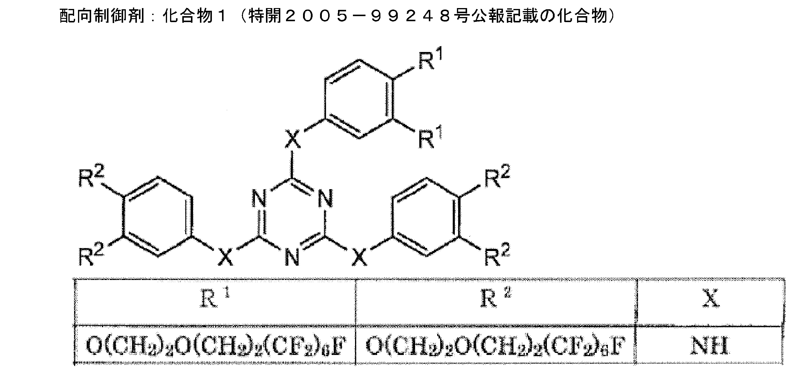

また、塗布液(R1)のキラル剤LC-756の処方量を変更し、下記表6に記載の反射波長となるように変更した以外は塗布液(R1)の調製と同様にして塗布液(R2)~(R4)を調製した。塗布液(R1)~(R4)の反射中心波長を下記表6に示す。
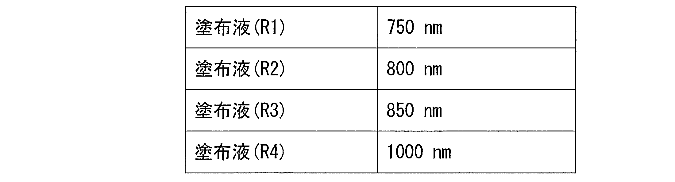
また、塗布液(L1)のキラル剤化合物2の処方量を変更し、下記表7に記載の反射波長となるように変更した以外は塗布液(L1)の調製と同様にして塗布液(L2)および(L3)を調製した。塗布液(L1)~(L3)の反射中心波長を下記表7に示す。
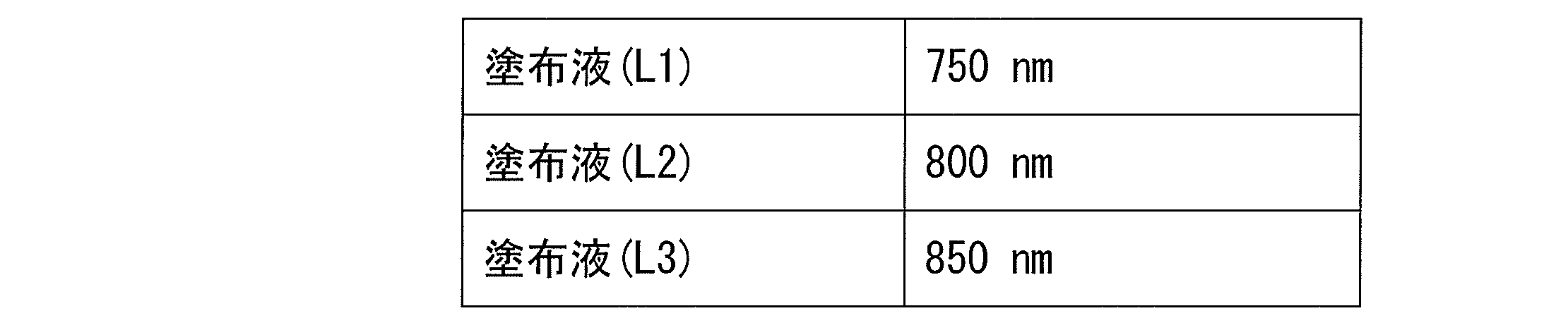
[実施例1]
<赤外線カットフィルムの作成>
PET上に、製造例2で調製した塗布液(R1)を塗布し、以下の方法Yの条件にて製膜した。
<赤外線カットフィルムの作成>
PET上に、製造例2で調製した塗布液(R1)を塗布し、以下の方法Yの条件にて製膜した。
(近赤外線反射層の作製:方法Y)
調製した塗布液(R1)を用い、下記の手順にて近赤外線反射層を作製した。基板としては、富士フイルム(株)製PETフィルム(下塗り層無し、厚み:188μm)を使用した。
(1)塗布液を、ワイヤーバーを用いて、乾燥後の膜の厚みが6μmになるように、PETフィルム上に、室温にて塗布した。
(2)室温にて30秒間乾燥させて溶剤を除去した後、125℃の雰囲気で2分間加熱し、その後95℃でコレステリック液晶相とした。次いで、フージョンUVシステムズ(株)製無電極ランプ「Dバルブ」(90mW/cm)にて、出力60%で6~12秒間UV照射し、コレステリック液晶相を固定して、膜(近赤外線反射層)を作製した。
得られたPETフィルム上に塗布液(R1)が方法Yの条件にて製膜された積層体について、日本分光製V-670を用いて反射スペクトルを測定したところ、750nmにおける反射率は48%であった。
調製した塗布液(R1)を用い、下記の手順にて近赤外線反射層を作製した。基板としては、富士フイルム(株)製PETフィルム(下塗り層無し、厚み:188μm)を使用した。
(1)塗布液を、ワイヤーバーを用いて、乾燥後の膜の厚みが6μmになるように、PETフィルム上に、室温にて塗布した。
(2)室温にて30秒間乾燥させて溶剤を除去した後、125℃の雰囲気で2分間加熱し、その後95℃でコレステリック液晶相とした。次いで、フージョンUVシステムズ(株)製無電極ランプ「Dバルブ」(90mW/cm)にて、出力60%で6~12秒間UV照射し、コレステリック液晶相を固定して、膜(近赤外線反射層)を作製した。
得られたPETフィルム上に塗布液(R1)が方法Yの条件にて製膜された積層体について、日本分光製V-670を用いて反射スペクトルを測定したところ、750nmにおける反射率は48%であった。
上記にて製膜した近赤外線反射層の上に、塗布液(B-1)を塗布し、以下の方法Xの条件にて製膜して近赤外線吸収層を作製し、赤外線カットフィルムF1を得た。
(近赤外線吸収層の作製:方法X)
塗布液(B-1)をワイヤーバーを用いて、乾燥後の膜厚が1μmになるように近赤外線反射層(液晶膜)上に室温にて塗布した。室温にて90秒間乾燥させて溶剤を除去した後、90℃の雰囲気で90秒間加熱した。次いで、フージョンUVシステムズ(株)製無電極ランプ「Dバルブ」(90mW/cm)にて、出力60%で3~6秒間UV照射し、近赤外線吸収層を作製した。
塗布液(B-1)をワイヤーバーを用いて、乾燥後の膜厚が1μmになるように近赤外線反射層(液晶膜)上に室温にて塗布した。室温にて90秒間乾燥させて溶剤を除去した後、90℃の雰囲気で90秒間加熱した。次いで、フージョンUVシステムズ(株)製無電極ランプ「Dバルブ」(90mW/cm)にて、出力60%で3~6秒間UV照射し、近赤外線吸収層を作製した。
得られた赤外線フィルムF1を実施例1の赤外線カットフィルムとした。
<評価>
(不可視性)
作製した赤外線カットフィルムについて、日本分光(株)製分光光度計「V-670」にて550nmの波長の透過率を算出した。
550nmの透過率が80%以上ならば○、80%未満ならば×と評価した。
得られた結果を下記表8に記載した。
(不可視性)
作製した赤外線カットフィルムについて、日本分光(株)製分光光度計「V-670」にて550nmの波長の透過率を算出した。
550nmの透過率が80%以上ならば○、80%未満ならば×と評価した。
得られた結果を下記表8に記載した。
(耐光性)
作製した赤外線カットフィルムに対して、22万ルクスのキセノンランプを72時間照射した。光照射後の近赤外線吸収層の極大吸収波長における吸光度を測定し、光照射前の近赤外線吸収層の極大吸収波長における吸光度に対する残存比を求めた。
残存比=(光照射後の吸光度)÷(光照射前の吸光度)×100
残存比が90%以上ならば○、90%未満ならば×と評価した。
得られた結果を下記表8に記載した。
作製した赤外線カットフィルムに対して、22万ルクスのキセノンランプを72時間照射した。光照射後の近赤外線吸収層の極大吸収波長における吸光度を測定し、光照射前の近赤外線吸収層の極大吸収波長における吸光度に対する残存比を求めた。
残存比=(光照射後の吸光度)÷(光照射前の吸光度)×100
残存比が90%以上ならば○、90%未満ならば×と評価した。
得られた結果を下記表8に記載した。
(遮熱性能)
作製した赤外線カットフィルムについて、350nm~2,100nmまで測定した各波長の透過率、反射率から、JIS5759記載の方法に基づき、日射反射率を求め、判定を行った。遮熱性能の評価としては、反射率が高いことが好ましい。
○:反射率10%以上
×:反射率10%未満
作製した赤外線カットフィルムについて、350nm~2,100nmまで測定した各波長の透過率、反射率から、JIS5759記載の方法に基づき、日射反射率を求め、判定を行った。遮熱性能の評価としては、反射率が高いことが好ましい。
○:反射率10%以上
×:反射率10%未満
[実施例2]
実施例1において、塗布液(B-1)の代わりに塗布液(B-2)を用いた以外は実施例1と同様にして、赤外線フィルムF2を得た。
得られた赤外線フィルムF2を実施例2の赤外線カットフィルムとした。
実施例2の赤外線カットフィルムについて、実施例1と同様にして不可視性と耐光性と遮熱性能を評価した。その結果を下記表8に記載した。
実施例1において、塗布液(B-1)の代わりに塗布液(B-2)を用いた以外は実施例1と同様にして、赤外線フィルムF2を得た。
得られた赤外線フィルムF2を実施例2の赤外線カットフィルムとした。
実施例2の赤外線カットフィルムについて、実施例1と同様にして不可視性と耐光性と遮熱性能を評価した。その結果を下記表8に記載した。
[比較例1]
(近赤外線吸収層用の塗布液(B-3)の調製)
特開2001-106689号公報の実施例3に記載のフタロシアニン2部をシクロヘキサノン98部と混合し、近赤外線吸収層用の塗布液(B-3)を作成した。塗布液(B-3)をシクロヘキサノンで希釈し吸収スペクトルを測定した。極大吸収波長は850nmであり、極大吸収波長における吸光度が1のときの550nmにおける吸光度は0.1を超えており、着色が認められた。
(近赤外線吸収層用の塗布液(B-3)の調製)
特開2001-106689号公報の実施例3に記載のフタロシアニン2部をシクロヘキサノン98部と混合し、近赤外線吸収層用の塗布液(B-3)を作成した。塗布液(B-3)をシクロヘキサノンで希釈し吸収スペクトルを測定した。極大吸収波長は850nmであり、極大吸収波長における吸光度が1のときの550nmにおける吸光度は0.1を超えており、着色が認められた。
(赤外線カットフィルムの作製)
実施例1において、塗布液(B-1)の代わりに塗布液(B-3)を用いた以外は実施例1と同様にして、赤外線フィルムE1を得た。
得られた赤外線フィルムE1を比較例1の赤外線カットフィルムとした。
比較例1の赤外線カットフィルムについて、実施例1と同様にして不可視性と耐光性と遮熱性能を評価した。その結果を下記表8に記載した。
実施例1において、塗布液(B-1)の代わりに塗布液(B-3)を用いた以外は実施例1と同様にして、赤外線フィルムE1を得た。
得られた赤外線フィルムE1を比較例1の赤外線カットフィルムとした。
比較例1の赤外線カットフィルムについて、実施例1と同様にして不可視性と耐光性と遮熱性能を評価した。その結果を下記表8に記載した。
[比較例2]
(赤外線カットフィルムの作製)
PET上に塗布液(B-1)を塗布し、前記の方法Xの条件にて製膜して近赤外線吸収層を作製し、赤外線カットフィルムE2を得た。得られた赤外線フィルムE2を比較例2の赤外線カットフィルムとした。
比較例2の赤外線カットフィルムについて、実施例1と同様にして不可視性と耐光性と遮熱性能を評価した。その結果を下記表8に記載した。
(赤外線カットフィルムの作製)
PET上に塗布液(B-1)を塗布し、前記の方法Xの条件にて製膜して近赤外線吸収層を作製し、赤外線カットフィルムE2を得た。得られた赤外線フィルムE2を比較例2の赤外線カットフィルムとした。
比較例2の赤外線カットフィルムについて、実施例1と同様にして不可視性と耐光性と遮熱性能を評価した。その結果を下記表8に記載した。
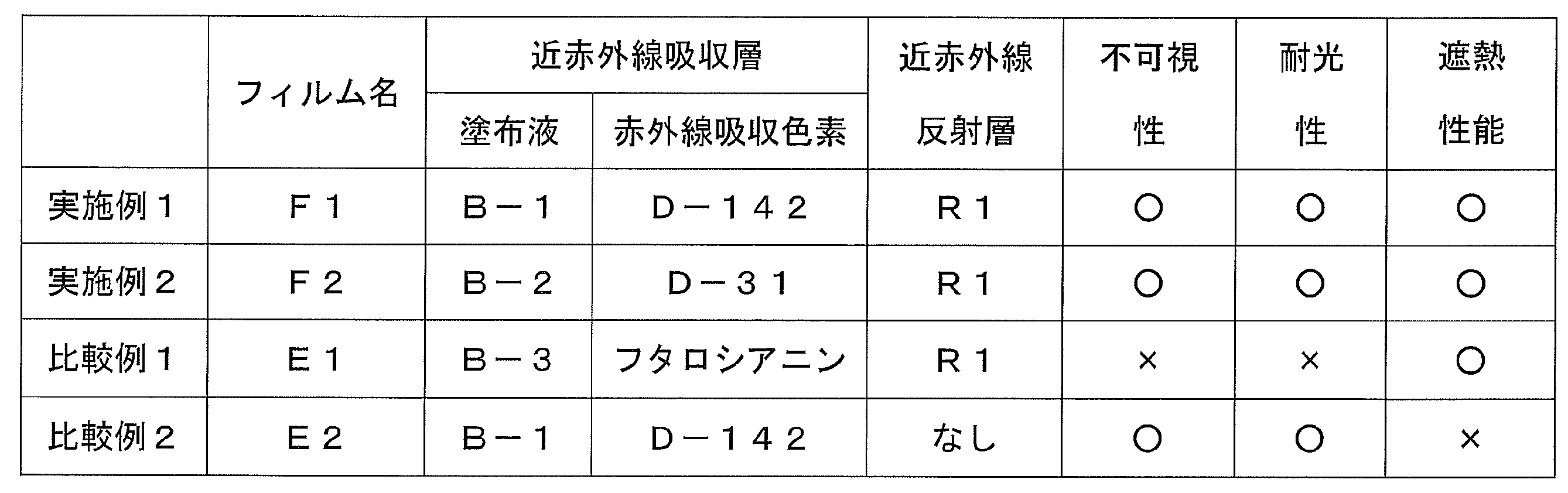
上記表8よりより、本発明によれば、不可視性および堅牢性がともに優れ、遮熱性能の高い赤外線カットフィルムが得られた。
[実施例3]
<近赤外線反射層を2層以上積層した赤外線カットフィルムの作製>
製造例2で調製した塗布液(R2)、(L2)を用い、下記の手順にて近赤外線反射層を作製した。基板としては、富士フイルム(株)製PETフィルム(下塗り層無し、厚み:188μm)を使用した。
(1)各塗布液を、ワイヤーバーを用いて、乾燥後の膜の厚みが6μmになるように、PETフィルム上に、室温にて塗布した。
(2)室温にて30秒間乾燥させて溶剤を除去した後、125℃の雰囲気で2分間加熱し、その後95℃でコレステリック液晶相とした。次いで、フージョンUVシステムズ(株)製無電極ランプ「Dバルブ」(90mW/cm)にて、出力60%で6~12秒間UV照射し、コレステリック液晶相を固定して、膜(光反射層)を作製した。
(3)室温まで冷却した後、上記工程(1)及び(2)を繰り返し、2層積層されたコレステリック液晶相を有する近赤外線反射層を作製した。なお、塗布液は、(R2)、(L2)の順番に塗布を行なった。
さらに、実施例1において、PET上に塗布液(R1)から形成された近赤外線反射層が積層された積層体の代わりに、上記にて得られたPET上に近赤外線反射層が2層積層された積層体を用いた以外は実施例1と同様にして塗布液(B-1)を用いて近赤外線吸収層を製膜し、赤外線カットフィルムF3を得た。
得られた赤外線フィルムF3を実施例3の赤外線カットフィルムとした。
<近赤外線反射層を2層以上積層した赤外線カットフィルムの作製>
製造例2で調製した塗布液(R2)、(L2)を用い、下記の手順にて近赤外線反射層を作製した。基板としては、富士フイルム(株)製PETフィルム(下塗り層無し、厚み:188μm)を使用した。
(1)各塗布液を、ワイヤーバーを用いて、乾燥後の膜の厚みが6μmになるように、PETフィルム上に、室温にて塗布した。
(2)室温にて30秒間乾燥させて溶剤を除去した後、125℃の雰囲気で2分間加熱し、その後95℃でコレステリック液晶相とした。次いで、フージョンUVシステムズ(株)製無電極ランプ「Dバルブ」(90mW/cm)にて、出力60%で6~12秒間UV照射し、コレステリック液晶相を固定して、膜(光反射層)を作製した。
(3)室温まで冷却した後、上記工程(1)及び(2)を繰り返し、2層積層されたコレステリック液晶相を有する近赤外線反射層を作製した。なお、塗布液は、(R2)、(L2)の順番に塗布を行なった。
さらに、実施例1において、PET上に塗布液(R1)から形成された近赤外線反射層が積層された積層体の代わりに、上記にて得られたPET上に近赤外線反射層が2層積層された積層体を用いた以外は実施例1と同様にして塗布液(B-1)を用いて近赤外線吸収層を製膜し、赤外線カットフィルムF3を得た。
得られた赤外線フィルムF3を実施例3の赤外線カットフィルムとした。
[実施例4]
実施例2において、PET上に塗布液(R1)から形成された近赤外線反射層が積層された積層体の代わりに、実施例3で製膜したPET上に近赤外線反射層が2層積層された積層体を用いた以外は実施例2と同様にして、塗布液(B-2)を用いて近赤外線吸収層を製膜し、赤外線カットフィルムF4を得た。
得られた赤外線フィルムF4を実施例4の赤外線カットフィルムとした。
実施例2において、PET上に塗布液(R1)から形成された近赤外線反射層が積層された積層体の代わりに、実施例3で製膜したPET上に近赤外線反射層が2層積層された積層体を用いた以外は実施例2と同様にして、塗布液(B-2)を用いて近赤外線吸収層を製膜し、赤外線カットフィルムF4を得た。
得られた赤外線フィルムF4を実施例4の赤外線カットフィルムとした。
[比較例3]
実施例3で製膜したPET上に近赤外線反射層が2層積層された積層体を、赤外線カットフィルムE3とし、これを比較例3の赤外線カットフィルムとした。なお、比較例3の赤外線カットフィルムは、近赤外線吸収層を含まない。
実施例3で製膜したPET上に近赤外線反射層が2層積層された積層体を、赤外線カットフィルムE3とし、これを比較例3の赤外線カットフィルムとした。なお、比較例3の赤外線カットフィルムは、近赤外線吸収層を含まない。
<評価>
実施例3、4および比較例3の赤外線カットフィルムについて、実施例1と同様に不可視性と耐光性と遮熱性能を評価したところ、いずれも「○評価」であった。
実施例3、4および比較例3の赤外線カットフィルムについて、実施例1と同様に不可視性と耐光性と遮熱性能を評価したところ、いずれも「○評価」であった。
(吸収層によるギラツキ軽減試験)
赤外線カットフィルムF3、F4およびE3を、PETが下になるように平らな机の上の白い紙の上に置き、蛍光灯の下で斜めからフィルムを観察した。比較例3の赤外線カットフィルムE3は赤色光によるギラツキが確認されたが、実施例3の赤外線カットフィルムF3ではそれが軽減され、実施例4の赤外線カットフィルムF4ではギラツキの程度がさらに軽減され、目立たなかった。
赤外線カットフィルムF3、F4およびE3を、PETが下になるように平らな机の上の白い紙の上に置き、蛍光灯の下で斜めからフィルムを観察した。比較例3の赤外線カットフィルムE3は赤色光によるギラツキが確認されたが、実施例3の赤外線カットフィルムF3ではそれが軽減され、実施例4の赤外線カットフィルムF4ではギラツキの程度がさらに軽減され、目立たなかった。
[実施例5]
<赤外線カットフィルムを用いた合わせガラスの作製>
(塗布液の調製)
易接着層用塗布液(U1)は下記の組成に従って調製した。
スチレン-アクリル樹脂アロンS-1001
(東亞合成(株)製、固形分濃度50%) 20質量部
メトキシプロピルアセテート(PGMEA) 80質量部
<赤外線カットフィルムを用いた合わせガラスの作製>
(塗布液の調製)
易接着層用塗布液(U1)は下記の組成に従って調製した。
スチレン-アクリル樹脂アロンS-1001
(東亞合成(株)製、固形分濃度50%) 20質量部
メトキシプロピルアセテート(PGMEA) 80質量部
下塗り層用塗布液(S1)は下記の組成に従って調製した。
アクリルエステル樹脂ジュリマーET-410
(東亞合成(株)製、固形分濃度30%) 50質量部
メタノール 50質量部
アクリルエステル樹脂ジュリマーET-410
(東亞合成(株)製、固形分濃度30%) 50質量部
メタノール 50質量部
下塗り層用塗布液(S2)は、ITO微粒子とメタノールとを混合し、30分間、超音波分散処理を行って、平均分散粒子系60nmのITO微粒子が分散した液を調製した後、アクリルエステル樹脂と混合して下記の組成に従って調製した。
アクリルエステル樹脂ジュリマーET-410
(東亞合成(株)製、固形分濃度30%) 45質量部
メタノール 53.5質量部
ITO微粒子(平均粒子径30nm) 1.5質量部
アクリルエステル樹脂ジュリマーET-410
(東亞合成(株)製、固形分濃度30%) 45質量部
メタノール 53.5質量部
ITO微粒子(平均粒子径30nm) 1.5質量部
配向層用塗布液(H1)は下記の組成に従って調製した。
変性ポリビニルアルコールPVA203(クラレ社製) 10質量部
グルタルアルデヒド 0.5質量部
水 371質量部
メタノール 119質量部
変性ポリビニルアルコールPVA203(クラレ社製) 10質量部
グルタルアルデヒド 0.5質量部
水 371質量部
メタノール 119質量部
下記表9に示す組成のタングステン酸化物塗布液(C1)を調製した。

下記に示す組成の易接着層用塗布液(I1)を調製した。
ポリビニルブチラール樹脂B1776(長春株式会社(台湾)製)
10質量部
メトキシプロピルアセテート(PGMEA) 100質量部
ポリビニルブチラール樹脂B1776(長春株式会社(台湾)製)
10質量部
メトキシプロピルアセテート(PGMEA) 100質量部
ジインモニウム色素を含有する易接着層用塗布液(I2)は、ジインモニウム色素と、メチルエチルケトンとを混合したのち、ポリビニルブチラール樹脂と混合して下記の組成に従って調製した。
ポリビニルブチラール樹脂B1776(長春株式会社(台湾)製)
10質量部
メチルエチルケトン(MEK) 100質量部
ジインモニウム色素CIR-RL(日本カーリット製) 1.5質量部
ポリビニルブチラール樹脂B1776(長春株式会社(台湾)製)
10質量部
メチルエチルケトン(MEK) 100質量部
ジインモニウム色素CIR-RL(日本カーリット製) 1.5質量部
(赤外線カットフィルムの作製)
易接着層用塗布液(U1)を、ワイヤーバーを用いて、乾燥後の膜厚が0.5μmになるようにPETフィルム(富士フイルム(株)製、厚み:188μm)上に塗布した。その後、150℃で10分間加熱し、乾燥、固化し、易接着層(アンダーコート層)を形成した。
次いで、上記で作製した易接着層付PETフィルムの易接着層が塗布されていない側の表面上に、下塗り層用塗布液(S1)を、ワイヤーバーを用いて、乾燥後の膜厚が0.25μmになるように塗布した。その後、150℃で10分間加熱し、乾燥、固化し、下塗り層を形成した。
次いで、形成した下塗り層の上に、配向層用塗布液(H1)を、ワイヤーバーを用いて、乾燥後の膜厚が1.0μmになるように塗布した。その後、100℃で2分間加熱し、乾燥、固化し、配向層を形成した。配向層に対し、ラビング処理(レーヨン布、圧力:0.1kgf、回転数:1000rpm、搬送速度:10m/min、回数:1往復)を施した。
次いで、形成した配向層の上に、塗布液(R3)、(R4)、(L3)を用い、実施例3の近赤外線反射層の形成方法の条件と同様にし、3層積層されたコレステリック液晶相の近赤外線反射層を形成した。
次いで、上記で形成した近赤外線光反射層の表面に、近赤外線吸収層用の塗布液(B-1)を実施例1と同様の方法の条件で積層し、ついでタングステン酸化物塗布液(C1)を積層した。塗布液(C1)の積層条件は、近赤外線吸収層用の塗布液(B-1)の塗布方法の塗布後の膜厚を2μmとなるように変更し、それ以外は近赤外線吸収層用の塗布液(B-1)の塗布方法と同様の方法で行った。さらに、タングステン酸化物塗布液(C1)の上に、易接着層用塗布液(I1)を、ワイヤーバーを用いて、乾燥後の膜厚が1.0μmになるように塗布した。その後、150℃で10分間加熱し、乾燥、固化し、易接着層を形成し、赤外線カットフィルムF5を作製した。
易接着層用塗布液(U1)を、ワイヤーバーを用いて、乾燥後の膜厚が0.5μmになるようにPETフィルム(富士フイルム(株)製、厚み:188μm)上に塗布した。その後、150℃で10分間加熱し、乾燥、固化し、易接着層(アンダーコート層)を形成した。
次いで、上記で作製した易接着層付PETフィルムの易接着層が塗布されていない側の表面上に、下塗り層用塗布液(S1)を、ワイヤーバーを用いて、乾燥後の膜厚が0.25μmになるように塗布した。その後、150℃で10分間加熱し、乾燥、固化し、下塗り層を形成した。
次いで、形成した下塗り層の上に、配向層用塗布液(H1)を、ワイヤーバーを用いて、乾燥後の膜厚が1.0μmになるように塗布した。その後、100℃で2分間加熱し、乾燥、固化し、配向層を形成した。配向層に対し、ラビング処理(レーヨン布、圧力:0.1kgf、回転数:1000rpm、搬送速度:10m/min、回数:1往復)を施した。
次いで、形成した配向層の上に、塗布液(R3)、(R4)、(L3)を用い、実施例3の近赤外線反射層の形成方法の条件と同様にし、3層積層されたコレステリック液晶相の近赤外線反射層を形成した。
次いで、上記で形成した近赤外線光反射層の表面に、近赤外線吸収層用の塗布液(B-1)を実施例1と同様の方法の条件で積層し、ついでタングステン酸化物塗布液(C1)を積層した。塗布液(C1)の積層条件は、近赤外線吸収層用の塗布液(B-1)の塗布方法の塗布後の膜厚を2μmとなるように変更し、それ以外は近赤外線吸収層用の塗布液(B-1)の塗布方法と同様の方法で行った。さらに、タングステン酸化物塗布液(C1)の上に、易接着層用塗布液(I1)を、ワイヤーバーを用いて、乾燥後の膜厚が1.0μmになるように塗布した。その後、150℃で10分間加熱し、乾燥、固化し、易接着層を形成し、赤外線カットフィルムF5を作製した。
(赤外線カット合わせガラスの作製)
次いで、上記で作製した赤外線カットフィルムF5と合わせガラス用ポリビニルブチラール中間膜シート(厚み:380μm)とを、ラミネーター(大成ラミネーター(株)製)を用いてラミネート処理(加熱温度:80℃、加圧力:1.5kg/cm2、搬送速度:0.1m/min)することにより、合わせガラス用積層中間膜シートを作製した。
次いで、上記で作製した合わせガラス用積層中間膜シートを2枚の透明ガラス(厚さ:2mm)で挟み、ゴムバッグに入れ、真空ポンプで減圧した。その後、減圧下で90℃まで昇温し、30分間保持後、いったん常温常圧まで戻した。その後、オートクレーブ内にて圧力1.3MPa、温度130℃の条件で20分間保持した。これを常温常圧まで戻し、赤外線カット合わせガラスG1を作製した。
次いで、上記で作製した赤外線カットフィルムF5と合わせガラス用ポリビニルブチラール中間膜シート(厚み:380μm)とを、ラミネーター(大成ラミネーター(株)製)を用いてラミネート処理(加熱温度:80℃、加圧力:1.5kg/cm2、搬送速度:0.1m/min)することにより、合わせガラス用積層中間膜シートを作製した。
次いで、上記で作製した合わせガラス用積層中間膜シートを2枚の透明ガラス(厚さ:2mm)で挟み、ゴムバッグに入れ、真空ポンプで減圧した。その後、減圧下で90℃まで昇温し、30分間保持後、いったん常温常圧まで戻した。その後、オートクレーブ内にて圧力1.3MPa、温度130℃の条件で20分間保持した。これを常温常圧まで戻し、赤外線カット合わせガラスG1を作製した。
[実施例6]
(赤外線カットフィルムの作製)
易接着層用塗布液(U1)を、ワイヤーバーを用いて、乾燥後の膜厚が0.5μmになるようにPETフィルム(富士フイルム(株)製、厚み:188μm)上に塗布した。その後、150℃で10分間加熱し、乾燥、固化し、易接着層(アンダーコート層)を形成した。
次いで、上記で作製した易接着層付PETフィルムの易接着層が塗布されていない側の表面上に、下塗り層用塗布液(S2)を、ワイヤーバーを用いて、乾燥後の膜厚が0.25μmになるように塗布した。その後、150℃で10分間加熱し、乾燥、固化し、下塗り層を形成した。
次いで、形成した下塗り層の上に、配向層用塗布液(H1)を、ワイヤーバーを用いて、乾燥後の膜厚が1.0μmになるように塗布した。その後、100℃で2分間加熱し、乾燥、固化し、配向層を形成した。配向層に対し、ラビング処理(レーヨン布、圧力:0.1kgf、回転数:1000rpm、搬送速度:10m/min、回数:1往復)を施した。
次いで、形成した配向層の上に、塗布液(R3)、(R4)、(L3)を用い、実施例3の近赤外線反射層の形成方法の条件と同様にし、3層積層されたコレステリック液晶相の近赤外線反射層を形成した。
次いで、上記で形成した近赤外線反射層の表面に、近赤外線吸収層用の塗布液(B-1)を実施例1と同様の方法の条件で積層した。次いで、ジインモニウム色素を含有する易接着層用塗布液(I2)を、ワイヤーバーを用いて、乾燥後の膜厚が1.0μmになるように塗布した。その後、100℃で10分間加熱し、乾燥、固化し、易接着層を形成し、赤外線カットフィルムF6を作製した。
(赤外線カット合わせガラスの作製)
次いで、上記で作製した赤外線カットフィルムF6と合わせガラス用ポリビニルブチラール中間膜シート(厚み:380μm)とを、ラミネーター(大成ラミネーター(株)製)を用いてラミネート処理(加熱温度:80℃、加圧力:1.5kg/cm2、搬送速度:0.1m/min)することにより、合わせガラス用積層中間膜シートを作製した。
次いで、上記で作製した合わせガラス用積層中間膜シートを2枚の透明ガラス(厚さ:2mm)で挟み、ゴムバッグに入れ、真空ポンプで減圧した。その後、減圧下で90℃まで昇温し、30分間保持後、いったん常温常圧まで戻した。その後、オートクレーブ内にて圧力1.3MPa、温度130℃の条件で20分間保持した。これを常温常圧まで戻し、赤外線カット合わせガラスG2を作製した。
(赤外線カットフィルムの作製)
易接着層用塗布液(U1)を、ワイヤーバーを用いて、乾燥後の膜厚が0.5μmになるようにPETフィルム(富士フイルム(株)製、厚み:188μm)上に塗布した。その後、150℃で10分間加熱し、乾燥、固化し、易接着層(アンダーコート層)を形成した。
次いで、上記で作製した易接着層付PETフィルムの易接着層が塗布されていない側の表面上に、下塗り層用塗布液(S2)を、ワイヤーバーを用いて、乾燥後の膜厚が0.25μmになるように塗布した。その後、150℃で10分間加熱し、乾燥、固化し、下塗り層を形成した。
次いで、形成した下塗り層の上に、配向層用塗布液(H1)を、ワイヤーバーを用いて、乾燥後の膜厚が1.0μmになるように塗布した。その後、100℃で2分間加熱し、乾燥、固化し、配向層を形成した。配向層に対し、ラビング処理(レーヨン布、圧力:0.1kgf、回転数:1000rpm、搬送速度:10m/min、回数:1往復)を施した。
次いで、形成した配向層の上に、塗布液(R3)、(R4)、(L3)を用い、実施例3の近赤外線反射層の形成方法の条件と同様にし、3層積層されたコレステリック液晶相の近赤外線反射層を形成した。
次いで、上記で形成した近赤外線反射層の表面に、近赤外線吸収層用の塗布液(B-1)を実施例1と同様の方法の条件で積層した。次いで、ジインモニウム色素を含有する易接着層用塗布液(I2)を、ワイヤーバーを用いて、乾燥後の膜厚が1.0μmになるように塗布した。その後、100℃で10分間加熱し、乾燥、固化し、易接着層を形成し、赤外線カットフィルムF6を作製した。
(赤外線カット合わせガラスの作製)
次いで、上記で作製した赤外線カットフィルムF6と合わせガラス用ポリビニルブチラール中間膜シート(厚み:380μm)とを、ラミネーター(大成ラミネーター(株)製)を用いてラミネート処理(加熱温度:80℃、加圧力:1.5kg/cm2、搬送速度:0.1m/min)することにより、合わせガラス用積層中間膜シートを作製した。
次いで、上記で作製した合わせガラス用積層中間膜シートを2枚の透明ガラス(厚さ:2mm)で挟み、ゴムバッグに入れ、真空ポンプで減圧した。その後、減圧下で90℃まで昇温し、30分間保持後、いったん常温常圧まで戻した。その後、オートクレーブ内にて圧力1.3MPa、温度130℃の条件で20分間保持した。これを常温常圧まで戻し、赤外線カット合わせガラスG2を作製した。
<評価>
実施例5および6でそれぞれ作製した合わせガラスG1およびG2の透過スペクトルを測定した結果を下記図4および図5に示した。
JIS5759記載の方法に基づく、赤外線カット合わせガラスG1の可視光透過率は72.1%、赤外線カット合わせガラスG2の可視光透過率は76.2%であった。
図4および図5ならびに上記の可視光透過率の結果より、本発明の赤外線カット合わせガラスG1およびG2は可視光透過率が高く、また遮熱性能も非常に優れており、車や建材の窓用部材として好適に利用できる。さらに赤外線カット合わせガラスG1およびG2の可視光透過率は70%以上あるため、自動車のフロントガラス用としても好適に利用できる。
実施例5および6でそれぞれ作製した合わせガラスG1およびG2の透過スペクトルを測定した結果を下記図4および図5に示した。
JIS5759記載の方法に基づく、赤外線カット合わせガラスG1の可視光透過率は72.1%、赤外線カット合わせガラスG2の可視光透過率は76.2%であった。
図4および図5ならびに上記の可視光透過率の結果より、本発明の赤外線カット合わせガラスG1およびG2は可視光透過率が高く、また遮熱性能も非常に優れており、車や建材の窓用部材として好適に利用できる。さらに赤外線カット合わせガラスG1およびG2の可視光透過率は70%以上あるため、自動車のフロントガラス用としても好適に利用できる。
本発明の赤外線カットフィルムは、不可視性および堅牢性がともに優れ、遮熱性能にも優れるので、例えば自動車、バス等の乗り物用フィルムや貼合せ構造体、建材用フィルムや貼合せ構造体などとして、熱線の透過を防止することの求められる種々の部材として好適に利用可能である。
12 透明基材
14a コレステリック液晶層を固定化してなる近赤外線反射層
14b コレステリック液晶層を固定化してなる近赤外線反射層
19 近赤外線吸収剤を含む近赤外線吸収層
20 金属微粒子分散物またはジインモニウム色素を含む他の赤外線吸収層
14a コレステリック液晶層を固定化してなる近赤外線反射層
14b コレステリック液晶層を固定化してなる近赤外線反射層
19 近赤外線吸収剤を含む近赤外線吸収層
20 金属微粒子分散物またはジインモニウム色素を含む他の赤外線吸収層
Claims (15)
- 透明基材と、
極大吸収波長が750nm~920nmである近赤外線吸収剤を含む近赤外線吸収層と、
コレステリック液晶相を固定化してなる少なくとも1層の近赤外線反射層とを有し、
前記近赤外線吸収剤が、下記一般式(1)で表される化合物であることを特徴とする赤外線カットフィルム。

- 前記近赤外線吸収剤は極大吸収波長における吸光度が1のときに、550nmの吸光度が0.1以下であることを特徴とする請求項1に記載の赤外線カットフィルム。
- 前記近赤外線吸収剤が、前記一般式(1)で表される化合物の微粒子の分散状態であることを特徴とする請求項1または2に記載の赤外線カットフィルム。
- 前記微粒子の数平均粒径が5~500nmであることを特徴とする請求項3に記載の赤外線カットフィルム。
- 前記近赤外線吸収層は、紫外線硬化型樹脂または熱可塑性樹脂に前記微粒子が分散されたことを特徴とする請求項3または4に記載の赤外線カットフィルム。
- 前記近赤外線吸収層が、塗布により形成されてなることを特徴とする請求項1~5のいずれか一項に記載の赤外線カットフィルム。
- 前記近赤外線反射層のうち少なくとも1層は750nm~1100nmにおける反射率の極大値が40%以上であることを特徴とする請求項1~6のいずれか一項に記載の赤外線カットフィルム。
- 前記近赤外線反射層は、重合性液晶からなるコレステリック液晶を塗布し、配向させたのちに光重合によって固定化されてなることを特徴とする請求項1~7のいずれか一項に記載の赤外線カットフィルム。
- 前記近赤外線反射層が、互いに逆方向の円偏光を反射し、反射波長域が750nm~900nmにあって、中心反射波長が互いに等しい、2層のコレステリック液晶相が固定化された反射層を含むことを特徴とする請求項1~8のいずれか一項に記載の赤外線カットフィルム。
- さらに金属微粒子分散物およびジインモニウム色素のうち少なくとも一方を含むことを特徴とする請求項1~9のいずれか一項に記載の赤外線カットフィルム。
- 前記金属微粒子分散物が、下記一般式(I)で表される複合タングステン酸化物であることを特徴とする請求項10に記載の赤外線カットフィルム。
MxWOy・・・(I)
(M元素はCs、Na、Rb、K、Tl、In、Ba、Li、Ca、Sr、Fe、およびSnからなる群から選ばれる少なくとも1種、Wはタングステン、Oは酸素で、0.1≦x≦0.5、2.2≦y≦3.0) - 易接着層、ハードコート層、紫外線吸収層、粘着層および表面保護層のうち少なくとも1つをさらに有することを特徴とする請求項1~11のいずれか一項に記載の赤外線カットフィルム。
- 2枚のガラス板と、その間に挟持された請求項1~12のいずれか一項に記載の赤外線カットフィルムとを有することを特徴とする赤外線カット合わせガラス。
- 請求項1~12のいずれか一項に記載の赤外線カットフィルムを含み、建造物および車両の窓への張り合わせ用であることを特徴とする赤外線カット部材。
- 請求項1~12のいずれか一項に記載の赤外線カットフィルムを含み、車両のフロントガラス用であることを特徴とする赤外線カット部材。
Priority Applications (2)
| Application Number | Priority Date | Filing Date | Title |
|---|---|---|---|
| CN201380050388.XA CN104662453A (zh) | 2012-09-28 | 2013-09-12 | 红外线截止膜、红外线截止夹层玻璃和红外线截止部件 |
| US14/657,807 US9897731B2 (en) | 2012-09-28 | 2015-03-13 | Infrared ray cutting film, infrared ray cutting laminated glass, and infrared ray cutting member |
Applications Claiming Priority (2)
| Application Number | Priority Date | Filing Date | Title |
|---|---|---|---|
| JP2012218443A JP2014071356A (ja) | 2012-09-28 | 2012-09-28 | 赤外線カットフィルム、赤外線カット合わせガラスおよび赤外線カット部材 |
| JP2012-218443 | 2012-09-28 |
Related Child Applications (1)
| Application Number | Title | Priority Date | Filing Date |
|---|---|---|---|
| US14/657,807 Continuation US9897731B2 (en) | 2012-09-28 | 2015-03-13 | Infrared ray cutting film, infrared ray cutting laminated glass, and infrared ray cutting member |
Publications (2)
| Publication Number | Publication Date |
|---|---|
| WO2014050583A1 true WO2014050583A1 (ja) | 2014-04-03 |
| WO2014050583A8 WO2014050583A8 (ja) | 2015-03-12 |
Family
ID=50387990
Family Applications (1)
| Application Number | Title | Priority Date | Filing Date |
|---|---|---|---|
| PCT/JP2013/074631 Ceased WO2014050583A1 (ja) | 2012-09-28 | 2013-09-12 | 赤外線カットフィルム、赤外線カット合わせガラスおよび赤外線カット部材 |
Country Status (4)
| Country | Link |
|---|---|
| US (1) | US9897731B2 (ja) |
| JP (1) | JP2014071356A (ja) |
| CN (1) | CN104662453A (ja) |
| WO (1) | WO2014050583A1 (ja) |
Cited By (2)
| Publication number | Priority date | Publication date | Assignee | Title |
|---|---|---|---|---|
| US20180030161A1 (en) * | 2015-03-10 | 2018-02-01 | Fujifilm Corporation | Composition kit, laminate and method for producing same, and bandpass filter |
| WO2019044859A1 (ja) * | 2017-08-28 | 2019-03-07 | 富士フイルム株式会社 | 光学異方性膜、円偏光板、表示装置 |
Families Citing this family (21)
| Publication number | Priority date | Publication date | Assignee | Title |
|---|---|---|---|---|
| CN107250314B (zh) * | 2015-02-27 | 2019-11-12 | 富士胶片株式会社 | 近红外线吸收组合物、固化膜、近红外线吸收滤波器、固体成像元件及红外线传感器 |
| JP6606555B2 (ja) * | 2015-09-30 | 2019-11-13 | 富士フイルム株式会社 | 積層体、光学センサー、および、キット |
| JP2017097067A (ja) * | 2015-11-19 | 2017-06-01 | リンテック株式会社 | 黄変抑制用層構造及びウィンドウフィルム |
| TWI744286B (zh) * | 2016-02-26 | 2021-11-01 | 日商富士軟片股份有限公司 | 感放射線性組成物、光學濾波器、積層體、圖案形成方法、固體攝像元件、圖像顯示裝置及紅外線感測器 |
| CN106772746B (zh) * | 2016-12-26 | 2023-05-05 | 信阳舜宇光学有限公司 | 红外截止滤光片及其制备方法 |
| JP6698937B2 (ja) | 2017-03-02 | 2020-05-27 | 富士フイルム株式会社 | 組成物、膜、赤外線カットフィルタ、固体撮像素子、赤外線センサ、カメラモジュール、及び、新規な化合物 |
| JP6703184B2 (ja) | 2017-03-15 | 2020-06-03 | 富士フイルム株式会社 | 樹脂組成物、樹脂成形体及び樹脂成形体の製造方法 |
| CN107346084B (zh) * | 2017-07-21 | 2020-10-16 | 华南师范大学 | 一种全反射红外反射器件及其制备方法 |
| JP6267823B1 (ja) * | 2017-07-27 | 2018-01-24 | 日本板硝子株式会社 | 光学フィルタ、カメラモジュール、及び情報端末 |
| JP6976341B2 (ja) * | 2017-09-11 | 2021-12-08 | 富士フイルム株式会社 | 近赤外線吸収有機顔料、樹脂組成物、近赤外線吸収有機顔料の製造方法、近赤外線吸収有機顔料の分光調整方法、膜、積層体、近赤外線カットフィルタ、近赤外線透過フィルタ、固体撮像素子、画像表示装置および赤外線センサ |
| CN111095048A (zh) | 2017-09-21 | 2020-05-01 | 富士胶片株式会社 | 近红外线截止滤光片的制造方法、层叠体及套件 |
| JP2019066839A (ja) * | 2017-09-28 | 2019-04-25 | 三菱マテリアル株式会社 | 赤外線遮蔽膜形成用液組成物及びこれを用いた赤外線遮蔽膜の製造方法及び赤外線遮蔽膜 |
| CN108196332B (zh) * | 2017-11-20 | 2021-02-12 | 天津津航技术物理研究所 | 一种可滤除二氧化碳红外吸收干扰的中波红外反射滤光薄膜 |
| WO2019142538A1 (ja) * | 2018-01-19 | 2019-07-25 | 富士フイルム株式会社 | 組成物、硬化性組成物および化合物 |
| US12546924B2 (en) * | 2018-06-04 | 2026-02-10 | Hoya Corporation | Optical filter and imaging apparatus |
| WO2020175532A1 (ja) * | 2019-02-27 | 2020-09-03 | 富士フイルム株式会社 | 延伸フィルム、円偏光板、表示装置 |
| CN210072208U (zh) | 2019-05-29 | 2020-02-14 | 3M创新有限公司 | 显示装置 |
| CN111812904B (zh) * | 2020-07-15 | 2022-08-16 | 深圳市国华光电科技有限公司 | 一种液晶多层膜及其制备方法 |
| CN116348792A (zh) * | 2020-10-15 | 2023-06-27 | 3M创新有限公司 | 含有具有红外吸收粘合层的多层光学制品的光学装置 |
| CN112596140B (zh) * | 2020-11-26 | 2022-11-01 | 中国航空工业集团公司洛阳电光设备研究所 | 一种红外长波截止滤光片及制备方法 |
| JP2024017654A (ja) * | 2022-07-28 | 2024-02-08 | 富士フイルム株式会社 | 積層フィルム、ウインドシールドガラス、および、ヘッドアップディスプレイシステム |
Citations (6)
| Publication number | Priority date | Publication date | Assignee | Title |
|---|---|---|---|---|
| JP2008209574A (ja) * | 2007-02-26 | 2008-09-11 | Fujimori Kogyo Co Ltd | 近赤外線遮蔽用の両面粘着フィルム及びpdp用光学フィルター |
| JP2009227938A (ja) * | 2008-03-25 | 2009-10-08 | Dainippon Printing Co Ltd | 近赤外線吸収材 |
| JP2010111750A (ja) * | 2008-11-05 | 2010-05-20 | Fujifilm Corp | 光吸収性組成物 |
| JP2011068731A (ja) * | 2009-09-24 | 2011-04-07 | Fujifilm Corp | 近赤外吸収性色素を含有する硬化性組成物、インク用組成物および近赤外線吸収フィルタの製造方法 |
| JP2011107321A (ja) * | 2009-11-16 | 2011-06-02 | Dainippon Printing Co Ltd | ディスプレイ用赤外線遮蔽フィルタ及び画像表示装置 |
| JP2012013822A (ja) * | 2010-06-30 | 2012-01-19 | Fujifilm Corp | 光反射性フィルムの製造方法、及び光反射性フィルム |
Family Cites Families (5)
| Publication number | Priority date | Publication date | Assignee | Title |
|---|---|---|---|---|
| US20100025641A1 (en) | 2008-08-04 | 2010-02-04 | Fujifilm Corporation | Infrared region selective reflection coat and infrared region selective reflection film |
| JP5601768B2 (ja) | 2008-10-09 | 2014-10-08 | 富士フイルム株式会社 | 近赤外線吸収組成物、近赤外線吸収塗布物およびそれらの製造方法 |
| WO2010041769A1 (en) | 2008-10-09 | 2010-04-15 | Fujifilm Corporation | Near-infrared absorptive composition, near-infrared absorptive coated material, near-infrared absorptive liquid dispersion, near-infrared absorptive ink, printed material, and near-infrared absorptive image-forming composition |
| CN201526909U (zh) * | 2009-05-13 | 2010-07-14 | 李欣洋 | 一种使用arton滤光片的led光源 |
| JP2011154215A (ja) * | 2010-01-27 | 2011-08-11 | Fujifilm Corp | 赤外光反射板、合わせガラス用積層中間膜シート及びその製造方法、並びに合わせガラス |
-
2012
- 2012-09-28 JP JP2012218443A patent/JP2014071356A/ja active Pending
-
2013
- 2013-09-12 WO PCT/JP2013/074631 patent/WO2014050583A1/ja not_active Ceased
- 2013-09-12 CN CN201380050388.XA patent/CN104662453A/zh active Pending
-
2015
- 2015-03-13 US US14/657,807 patent/US9897731B2/en active Active
Patent Citations (6)
| Publication number | Priority date | Publication date | Assignee | Title |
|---|---|---|---|---|
| JP2008209574A (ja) * | 2007-02-26 | 2008-09-11 | Fujimori Kogyo Co Ltd | 近赤外線遮蔽用の両面粘着フィルム及びpdp用光学フィルター |
| JP2009227938A (ja) * | 2008-03-25 | 2009-10-08 | Dainippon Printing Co Ltd | 近赤外線吸収材 |
| JP2010111750A (ja) * | 2008-11-05 | 2010-05-20 | Fujifilm Corp | 光吸収性組成物 |
| JP2011068731A (ja) * | 2009-09-24 | 2011-04-07 | Fujifilm Corp | 近赤外吸収性色素を含有する硬化性組成物、インク用組成物および近赤外線吸収フィルタの製造方法 |
| JP2011107321A (ja) * | 2009-11-16 | 2011-06-02 | Dainippon Printing Co Ltd | ディスプレイ用赤外線遮蔽フィルタ及び画像表示装置 |
| JP2012013822A (ja) * | 2010-06-30 | 2012-01-19 | Fujifilm Corp | 光反射性フィルムの製造方法、及び光反射性フィルム |
Cited By (4)
| Publication number | Priority date | Publication date | Assignee | Title |
|---|---|---|---|---|
| US20180030161A1 (en) * | 2015-03-10 | 2018-02-01 | Fujifilm Corporation | Composition kit, laminate and method for producing same, and bandpass filter |
| WO2019044859A1 (ja) * | 2017-08-28 | 2019-03-07 | 富士フイルム株式会社 | 光学異方性膜、円偏光板、表示装置 |
| JPWO2019044859A1 (ja) * | 2017-08-28 | 2020-10-15 | 富士フイルム株式会社 | 光学異方性膜、円偏光板、表示装置 |
| JP7034166B2 (ja) | 2017-08-28 | 2022-03-11 | 富士フイルム株式会社 | 光学異方性膜、円偏光板、表示装置 |
Also Published As
| Publication number | Publication date |
|---|---|
| WO2014050583A8 (ja) | 2015-03-12 |
| JP2014071356A (ja) | 2014-04-21 |
| US9897731B2 (en) | 2018-02-20 |
| US20150185383A1 (en) | 2015-07-02 |
| CN104662453A (zh) | 2015-05-27 |
Similar Documents
| Publication | Publication Date | Title |
|---|---|---|
| WO2014050583A1 (ja) | 赤外線カットフィルム、赤外線カット合わせガラスおよび赤外線カット部材 | |
| JP5671365B2 (ja) | 赤外光反射板並びに合わせガラス用積層中間膜シート及び合わせガラスとそれらの製造方法 | |
| JP5961498B2 (ja) | 熱線カットフィルムおよびその製造方法、合わせガラス並びに熱線カット部材 | |
| WO2013146664A1 (ja) | 光反射層、光反射板並びに合わせガラス用積層中間膜シート及び合わせガラスとそれらの製造方法 | |
| JP5709710B2 (ja) | 赤外光反射層及び赤外光反射板並びにガラス用積層中間膜シート及び合わせガラスとそれらの製造方法 | |
| JP6872366B2 (ja) | 位相差フィルム | |
| JP2011154215A (ja) | 赤外光反射板、合わせガラス用積層中間膜シート及びその製造方法、並びに合わせガラス | |
| JP6427659B2 (ja) | 組成物キット、積層体およびその製造方法、バンドパスフィルター | |
| TW201429711A (zh) | 熱線遮蔽片 | |
| KR101768554B1 (ko) | 적외광 반사판 | |
| WO2013038969A1 (ja) | コレステリック液晶性混合物、フィルム、選択反射板、積層体および合わせガラス | |
| CN102460241A (zh) | 光反射膜的制造方法 | |
| JP2012101999A (ja) | 合わせガラス体およびそれに用いる積層体 | |
| WO2013146923A1 (ja) | コレステリック液晶性混合物、フィルム、赤外反射板、積層体および合わせガラス | |
| JP5688950B2 (ja) | 熱線遮蔽材 | |
| JP5457970B2 (ja) | 赤外光反射膜および赤外光反射板 | |
| JP2012162427A (ja) | 合わせガラスおよびその製造方法 | |
| TWI298102B (ja) | ||
| TWI308645B (en) | Protective film for polarizing plate, production method for the same, polarizing plate and liquid crystal display | |
| JP2014114191A (ja) | 合わせガラス用中間膜および合わせガラス | |
| JP2011116571A (ja) | 合わせガラス用積層中間膜シートの製造方法、積層中間膜シート、並びに機能性合わせガラス及びその製造方法 | |
| CN1703634A (zh) | 偏振镜及其制造方法、光学薄膜和图像显示装置 | |
| JP2005037905A (ja) | 高分子フィルム、偏光子、光学フィルムおよび画像表示装置 |
Legal Events
| Date | Code | Title | Description |
|---|---|---|---|
| 121 | Ep: the epo has been informed by wipo that ep was designated in this application |
Ref document number: 13840610 Country of ref document: EP Kind code of ref document: A1 |
|
| NENP | Non-entry into the national phase |
Ref country code: DE |
|
| 122 | Ep: pct application non-entry in european phase |
Ref document number: 13840610 Country of ref document: EP Kind code of ref document: A1 |