WO2014050428A1 - 基板洗浄装置及び基板洗浄方法 - Google Patents
基板洗浄装置及び基板洗浄方法 Download PDFInfo
- Publication number
- WO2014050428A1 WO2014050428A1 PCT/JP2013/073289 JP2013073289W WO2014050428A1 WO 2014050428 A1 WO2014050428 A1 WO 2014050428A1 JP 2013073289 W JP2013073289 W JP 2013073289W WO 2014050428 A1 WO2014050428 A1 WO 2014050428A1
- Authority
- WO
- WIPO (PCT)
- Prior art keywords
- substrate
- gas
- processing container
- cleaning
- wafer
- Prior art date
- Legal status (The legal status is an assumption and is not a legal conclusion. Google has not performed a legal analysis and makes no representation as to the accuracy of the status listed.)
- Ceased
Links
Images




Classifications
-
- H—ELECTRICITY
- H10—SEMICONDUCTOR DEVICES; ELECTRIC SOLID-STATE DEVICES NOT OTHERWISE PROVIDED FOR
- H10P—GENERIC PROCESSES OR APPARATUS FOR THE MANUFACTURE OR TREATMENT OF DEVICES COVERED BY CLASS H10
- H10P70/00—Cleaning of wafers, substrates or parts of devices
- H10P70/10—Cleaning before device manufacture, i.e. Begin-Of-Line process
- H10P70/15—Cleaning before device manufacture, i.e. Begin-Of-Line process by wet cleaning only
-
- H—ELECTRICITY
- H10—SEMICONDUCTOR DEVICES; ELECTRIC SOLID-STATE DEVICES NOT OTHERWISE PROVIDED FOR
- H10P—GENERIC PROCESSES OR APPARATUS FOR THE MANUFACTURE OR TREATMENT OF DEVICES COVERED BY CLASS H10
- H10P72/00—Handling or holding of wafers, substrates or devices during manufacture or treatment thereof
- H10P72/04—Apparatus for manufacture or treatment
- H10P72/0402—Apparatus for fluid treatment
- H10P72/0406—Apparatus for fluid treatment for cleaning followed by drying, rinsing, stripping, blasting or the like
- H10P72/0411—Apparatus for fluid treatment for cleaning followed by drying, rinsing, stripping, blasting or the like for wet cleaning or washing
- H10P72/0414—Apparatus for fluid treatment for cleaning followed by drying, rinsing, stripping, blasting or the like for wet cleaning or washing using mainly spraying means, e.g. nozzles
-
- B—PERFORMING OPERATIONS; TRANSPORTING
- B08—CLEANING
- B08B—CLEANING IN GENERAL; PREVENTION OF FOULING IN GENERAL
- B08B3/00—Cleaning by methods involving the use or presence of liquid or steam
- B08B3/04—Cleaning involving contact with liquid
- B08B3/10—Cleaning involving contact with liquid with additional treatment of the liquid or of the object being cleaned, e.g. by heat, by electricity or by vibration
- B08B3/12—Cleaning involving contact with liquid with additional treatment of the liquid or of the object being cleaned, e.g. by heat, by electricity or by vibration by sonic or ultrasonic vibrations
Definitions
- the present invention relates to a substrate cleaning apparatus and a substrate cleaning method for cleaning a substrate in a manufacturing process of, for example, a semiconductor device.
- a substrate such as a semiconductor wafer is cleaned.
- dip cleaning has been performed in which a plurality of substrates are immersed and cleaned in a large immersion tank.
- single-wafer type spin cleaning is becoming mainstream (for example, Japanese Patent Application Laid-Open No. 2009-71272).
- Single-wafer spin cleaning is capable of uniformly cleaning the surface of large-sized substrates, reducing the reattachment of contaminants removed by cleaning, and reducing the amount of cleaning liquid and rinsing pure water used.
- Ultrasonic waves are widely used for spin cleaning type substrate cleaning. This discharges the cleaning liquid from the ultrasonic nozzle onto the surface of the substrate while rotating the substrate in the cleaning chamber, and oscillates the ultrasonic vibrator built in the ultrasonic nozzle. Then, the ultrasonic wave is propagated to the substrate surface through the liquid film of the cleaning liquid, and the substrate surface is cleaned by using physical force such as collision of liquid due to vibration energy of the ultrasonic wave and centrifugal force. The cleaning liquid discharged on the surface of the substrate moves outward in the radial direction of the substrate along with particles separated by ultrasonic vibration due to the centrifugal force accompanying the rotation of the substrate, and flows out from the peripheral portion of the substrate into the cleaning chamber.
- the two-fluid spray method is known as a widely used method.
- particles are removed by generating minute droplets from a spray nozzle and colliding with a substrate, but it is difficult to remove minute particles of 50 nm or less. This is because there is almost no flow of water in the vicinity of the boundary between the substrate and water, and an effective force for removing particles cannot be given.
- the use of pure water causes problems such as material loss due to dissolution of the water-soluble material on the substrate surface, and the need for a large amount of isopropyl alcohol in the drying step after cleaning.
- the present invention provides a substrate cleaning apparatus and a substrate cleaning method capable of effectively removing particles on the substrate surface using ultrasonic waves.
- a substrate cleaning apparatus includes a processing container that accommodates a substrate, a substrate holding device that rotatably holds the substrate in the processing container, and a gas introduction device that introduces a concentration-adjusted gas into the processing container. And a detection device that detects a gas concentration in the processing container, and an ultrasonic generator that generates ultrasonic waves and propagates the ultrasonic waves to the surface of the substrate held by the substrate holding device. Then, the substrate cleaning apparatus of the present invention introduces the gas whose concentration is adjusted in the processing container by the gas introduction device, and generates the ultrasonic wave while adjusting the gas concentration in the processing container. The substrate is cleaned by ultrasonic waves.
- the substrate cleaning apparatus of the present invention may further include a cooling device for cooling the substrate.
- the gas introduction device may include a vaporization device that vaporizes a liquid and a flow rate adjusting device that supplies the vaporized gas into the processing container at a predetermined flow rate.
- the gas whose concentration is adjusted may be air containing moisture.
- the substrate cleaning apparatus of the present invention further includes a control unit that adjusts the concentration and / or flow rate of the gas introduced into the processing container by the gas introduction device based on the gas concentration detected by the detection device. It may be.
- the substrate cleaning method of the present invention cleans a substrate using ultrasonic waves generated by an ultrasonic generator.
- the substrate is carried into a processing container and is rotatably held by a substrate holding device.
- the substrate cleaning method of the present invention may further include a step of cooling the substrate before the step of cleaning the substrate.
- the substrate cleaning method of the present invention may continue cooling the substrate during the step of cleaning the substrate.
- the gas whose concentration is adjusted may be air containing moisture.
- the moisture concentration in the processing container is less than the saturated water vapor amount at the atmospheric temperature in the apparatus.
- gas molecules with a thickness of several molecular layers are attached to the surface of the substrate by introducing a gas whose concentration is adjusted in the processing vessel by the gas introduction device and adjusting the gas concentration in the processing vessel. Perform ultrasonic cleaning in the condition. Thereby, particles on the substrate surface can be effectively removed without causing pattern collapse or material loss due to ultrasonic waves.
- FIG. 4 is a schematic diagram for explaining a change in the state of the wafer surface caused by the cleaning method according to the embodiment of the present invention, and shows a state in which water molecules are attached to the surface of the wafer W;
- FIG. 5 is a schematic diagram for explaining a change in the state of the wafer surface caused by the cleaning method according to the embodiment of the present invention, and shows a state in which ultrasonic waves are propagated to the surface of the wafer W; It is a schematic diagram explaining the washing
- FIG. 1 is a longitudinal sectional view showing a schematic configuration of a cleaning apparatus 100 according to the present embodiment.
- the cleaning apparatus 100 is a processing container 1 capable of sealing the inside, and a substrate holding apparatus that is provided in the processing container 1 and holds a semiconductor wafer (hereinafter simply referred to as “wafer”) W that is an object to be processed.
- the spin chuck 10 is provided.
- the cleaning apparatus 100 includes a gas introduction device 20 that introduces a gas whose concentration is adjusted into the processing container 1, and a gas concentration sensor 30 as a detection device that detects the gas concentration in the processing container 1. .
- the cleaning apparatus 100 includes an ultrasonic generator 40 that generates ultrasonic waves and propagates the ultrasonic waves to the surface of the wafer W held by the spin chuck 10, and a cooling device 50 that cools the wafer W. Yes. Furthermore, the cleaning apparatus 100 includes a control unit 60 that controls each component in the cleaning apparatus 100.
- the cleaning apparatus 100 introduces a gas whose concentration is adjusted into the processing container 1 by the gas introduction apparatus 20, and adjusts the gas concentration in the processing container 1 while using the ultrasonic wave generated by the ultrasonic generator 40 to adjust the wafer. W is washed.
- the processing container 1 includes a top plate 1a, a side wall 1b, and a bottom wall 1c.
- the processing container 1 is made of a material such as aluminum or SUS, for example.
- a loading / unloading port for the wafer W is formed on one side surface of the processing container 1, and an opening / closing shutter is provided at the loading / unloading port.
- a spin chuck 10 is provided inside the processing container 1 as a rotation holding member that holds the wafer W by suction.
- the spin chuck 10 has a horizontal upper surface, and a suction port (not shown) for sucking, for example, the wafer W is provided on the upper surface. The wafer W can be sucked and held on the spin chuck 10 by suction from the suction port.
- the spin chuck 10 is connected to the drive unit 11 through a support 10a.
- the drive unit 11 includes a rotation drive unit such as a motor, and can rotate the wafer W held by the spin chuck 10 in a horizontal direction at a predetermined speed by rotating the support column 10a.
- the drive part 11 has a raising / lowering drive part, such as a cylinder, for example, and can move the spin chuck 10 containing the support
- a guide ring 12 is provided on the lower side of the spin chuck 10, and the outer peripheral edge of the guide ring 12 is bent downward and extends.
- a cup 13 is provided outside the spin chuck 10, the wafer W held by the spin chuck 10, and the guide ring 12 so as to surround the spin chuck 10. The cup 13 can receive and collect particles scattered or dropped from the wafer W.
- the upper portion of the cup 13 is formed with an opening 13a larger than the wafer W so that the spin chuck 10 holding the wafer W can move up and down. Further, a gap 14 serving as a discharge path is formed between the inner peripheral surface of the cup 13 and the bent outer peripheral edge of the guide ring 12.
- the lower part of the cup 13 forms a gas-liquid separation part by forming a curved path together with the outer peripheral edge part of the guide ring 12.
- An exhaust port 15 for exhausting the atmosphere in the cup 13 is formed in the inner region of the bottom of the cup 13, and an exhaust pipe 15 a is connected to the exhaust port 15. Further, a drain port 16 for discharging the collected liquid is formed in the outer region of the bottom portion of the cup 13, and a drain tube 16 a is connected to the drain port 16.
- the gas introduction device 20 introduces a gas whose concentration is adjusted into the processing container 1.
- the gas introduction device 20 includes a carrier gas source 21, a vaporizer 22 that vaporizes a liquid while introducing the carrier gas from the carrier gas source 21, and a pipe 23 that connects the carrier gas source 21 and the vaporizer 22. And a valve 24 provided in the pipe 23.
- the gas introduction device 20 includes a pipe 25 that supplies the gas vaporized by the vaporizer 22 into the processing container 1 and a flow rate adjusting device (mass flow controller (MFC)) that is provided in the pipe 25 and adjusts the flow rate of the supplied gas. ) 26 and a valve 27 provided in the pipe 25.
- MFC mass flow controller
- the gas introduction device 20 is connected to a gas introduction port 28 provided on the side wall 1 b of the processing container 1 by a pipe 25.
- the cleaning apparatus 100 may include, for example, a purge gas introduction apparatus for purging the inside of the processing container 1 as a gas introduction mechanism other than the gas introduction apparatus 20.
- the gas introduced into the processing container 1 by the gas introduction device 20 include organic solvents such as air containing moisture, nitrogen gas containing moisture, and methanol.
- the gas concentration in the processing container 1 can be strictly managed by introducing the gas whose concentration is adjusted into the processing container 1 by the gas introduction device 20. Further, the gas concentration in the processing container 1 can be detected by a gas concentration sensor 30 mounted so as to be exposed to the internal atmosphere via the side wall 1 b of the processing container 1. For example, when the gas introduced into the processing container 1 by the gas introducing device 20 is air containing moisture or nitrogen gas containing moisture, a hygrometer is used as the gas concentration sensor 30.
- the ultrasonic generator 40 generates an ultrasonic wave, applies the ultrasonic wave to the surface of the wafer W held by the spin chuck 10, and propagates it.
- the ultrasonic generator 40 includes an ultrasonic wave application head 41 including a vibrator (not shown), an arm member 42 that holds the ultrasonic wave application head 41, a head drive unit 43 that moves the ultrasonic wave application head 41, and an ultrasonic wave And an ultrasonic oscillator 44 that outputs a pulse signal toward the applying head 41.
- the head drive unit 43 moves the ultrasonic wave application head 41 relative to the wafer W while keeping the distance between the ultrasonic wave application head 41 and the surface of the wafer W constant.
- the ultrasonic oscillator 44 outputs a pulse signal to a vibrator (not shown) of the ultrasonic wave application head 41 based on a control signal from the control unit 60. As a result, the vibrator vibrates ultrasonically, and ultrasonic vibration is applied to the surface of the wafer W.
- the ultrasonic wave application head 41 since the ultrasonic wave application head 41 is used in a gas phase, it is preferable to use an ultrasonic wave application head 41 having an amplification facility (for example, a horn) or a heat propagation type vibrator.
- the cooling device 50 includes nozzles 51A and 51B, a refrigerant source 52 that supplies refrigerant to the nozzles 51A and 51B, and refrigerant supply pipes 53A and 53B that connect the nozzles 51A and 51B and the refrigerant source 52.
- the nozzle 51 ⁇ / b> A is arranged so that the coolant can be supplied to the back surface of the peripheral edge of the wafer W.
- the nozzle 51B is arranged so that the coolant can be supplied toward the back surface of the central portion of the wafer W through the coolant supply pipe 53B inserted into the support column 10a.
- the cooling device 50 can cool the wafer W by supplying the coolant cooled to a predetermined temperature from the coolant source 52 and spraying the coolant onto the back surface of the wafer W from the nozzles 51A and 51B.
- the refrigerant for example, He gas, CO 2 gas, or the like can be used.
- the wafer W may be cooled by, for example, a chiller mechanism.
- Each end device (for example, the spin chuck 10, the gas introduction device 20, the gas concentration sensor 30, the ultrasonic generator 40, the cooling device 50, etc.) constituting the cleaning device 100 is connected to the control unit 60 and controlled. It has become.
- the control unit 60 having a computer function includes a controller 61 having a CPU, a user interface 62 and a storage unit 63 connected to the controller 61.
- the user interface 62 includes a keyboard and a touch panel on which a process manager manages command input to manage the cleaning apparatus 100, a display that visualizes and displays the operating status of the cleaning apparatus 100, and the like.
- the storage unit 63 stores a recipe in which a control program (software) for realizing various processes executed by the cleaning apparatus 100 under the control of the controller 61 and processing condition data are recorded. Then, if necessary, an arbitrary control program or recipe is called from the storage unit 63 by an instruction from the user interface 62 and is executed by the controller 61, so that the processing container of the cleaning apparatus 100 is controlled under the control of the controller 61. A desired cleaning process is performed within 1.
- the controller 61 instructs each end device to operate or stop under the conditions defined in the recipe. For example, the controller 61 sends a control signal to the gas introduction device 20 in order to keep the gas concentration in the processing container 1 within a range based on the recipe, and instructs the operation and stop, as well as the gas introduced into the processing container 1 Adjust the flow rate and concentration. In this case, the controller 61 can also perform feedback control on the gas supply device 20 with reference to the signal of the detected value of the gas concentration in the processing container 1 detected by the gas concentration sensor 30. The controller 61 also sends a control signal to the spin chuck 10, the ultrasonic generator 40, the cooling device 50, etc. to instruct operation or stop, and the processing container 1 detected by the gas concentration sensor 30.
- the controller 61 can adjust the oscillation frequency or vibration amplitude of the ultrasonic wave generated by the ultrasonic generator 40 according to the detected value of the gas concentration in the processing container 1 detected by the gas concentration sensor 30. it can.
- the controller 61 can also send a control signal to the drive unit 11 to adjust the rotation speed of the spin chuck 10 in accordance with the detected value of the gas concentration in the processing container 1 detected by the gas concentration sensor 30.
- the controller 61 adjusts the cooling temperature of the wafer W by the cooling device 50 according to the detected value of the gas concentration in the processing container 1 detected by the gas concentration sensor 30, so that the temperature of the refrigerant, the injection amount, etc. It can also be adjusted.
- the recipes such as the control program and the processing condition data can be used by installing the recipe stored in the computer-readable recording medium 64 in the storage unit 63.
- the computer-readable recording medium 64 is not particularly limited, and for example, a CD-ROM, a hard disk, a flexible disk, a flash memory, a DVD, or the like can be used. Further, the recipe can be transmitted from other devices as needed via, for example, a dedicated line and used online.
- a cleaning process using the ultrasonic waves generated by the ultrasonic generator 40 is performed on the wafer W.
- the cleaning process in the cleaning apparatus 100 includes, for example, a process of carrying the wafer W into the processing container 1 and holding the wafer W rotatably by the spin chuck 10, introducing a gas into the processing container 1, and a gas concentration in the processing container 1.
- the wafer W is cleaned by generating ultrasonic waves by the ultrasonic generator 40 while propagating the wafer W and propagating the ultrasonic waves to the surface of the wafer W held by the spin chuck 10. And a process.
- each step will be described.
- the wafer W is loaded by an external transfer device with the loading / unloading port (not shown) of the processing container 1 opened.
- the spin chuck 10 is configured to be movable up and down by the drive unit 11 as described above, and transfers the wafer W to and from an external transfer device at the raised position.
- the wafer W is lowered while being held on the spin chuck 10 and set at the cleaning position.
- a gas having a predetermined concentration is introduced into the processing container 1 by the gas introduction device 20. That is, the valve 24 of the pipe 23 and the valve 27 of the pipe 25 are opened, and the carrier gas is introduced into the vaporizer 22 from the carrier gas source 21.
- the gas vaporized by the vaporizer 22 is supplied into the processing container 1 through the gas inlet 28 while the flow rate of the gas is adjusted by the mass flow controller 26.
- carrier gas dry air, dry nitrogen gas, etc. can be used, for example.
- examples of the liquid stored in the vaporizer 22 and to be vaporized include distilled water and organic solvents.
- the gas concentration in the processing container 1 is stabilized by continuing to supply the gas for 10 seconds to 300 seconds, for example.
- the humidity in the processing container 1 is, for example, 0.1% or more. It is preferable to adjust so that it may become less than the saturated water vapor amount in the atmospheric temperature in the container 1.
- FIG. When the humidity in the processing container 1 is less than 0.1%, it is difficult to attach water molecules to the surface of the wafer W with high efficiency. As a result, a liquid film is formed. In the present embodiment, no special control is required for the pressure in the processing container 1, and atmospheric pressure is preferable.
- the driving unit 11 is driven to generate ultrasonic waves by the ultrasonic generator 40 while rotating the wafer W held by the spin chuck 10 at a predetermined speed, and the surface of the wafer W held by the spin chuck 10 is generated.
- the wafer W is cleaned by propagating ultrasonic waves.
- a pulse signal is output from the ultrasonic oscillator 44 toward the ultrasonic wave application head 41 to apply ultrasonic vibration to the surface of the wafer W.
- the arm member 42 is moved by the head drive unit 43, and the ultrasonic wave application head 41 is scanned in the radial direction of the rotating wafer W.
- the vibration frequency of the ultrasonic wave applied from the ultrasonic wave application head 41 to the surface of the wafer W is preferably within the range of the sound pressure on the surface of the wafer W of 1 ⁇ 10 4 Pa or more and 1 ⁇ 10 6 Pa or less.
- the rotational speed of the wafer W is preferably in the range of, for example, 100 rpm or more and 1000 rpm or less from the viewpoint of efficiently scattering particles peeled off by ultrasonic waves in the outer diameter direction of the wafer W by centrifugal force.
- FIGS. 2 to 5B are schematic diagrams for explaining a change in the state of the surface of the wafer W caused by the cleaning method of the present embodiment.
- a case where air containing a predetermined concentration of water is introduced into the processing container 1 will be described as an example.
- 5A and 5B are schematic views for explaining the surface state of the wafer W in the cleaning method of the comparative example.
- FIG. 2 shows a state before cleaning. In this state, the humidity in the processing container 1 is not adjusted. A plurality of fine particles 101 are attached to the surface of the wafer W.
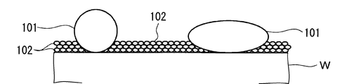
- FIG. 3 shows a state in which water molecules 102 are attached to the surface of the wafer W. This state is such that water molecules 102 of several layers, for example, 5 layers or less, preferably about 2 to 3 molecular layers are attached to the surface of the wafer W, and a liquid film is formed (completely wet state). ) Is different. The amount of adhesion is indistinguishable from the dry state by visual inspection.
- air containing a predetermined concentration of moisture is introduced into the processing container 1 by the gas introduction device 20, and the humidity in the processing container 1 is set to the above-described humidity. Can be produced by controlling within range.
- an ultrasonic wave U is generated by the ultrasonic wave generator 40, and the ultrasonic wave is propagated from the ultrasonic wave application head 41 to the surface of the wafer W held on the spin chuck 10.
- the particles 101 existing on the surface of the wafer W are effectively removed by physical force due to ultrasonic vibration. And can be removed from the surface of the wafer W.
- the particles 101 scattered or dropped from the wafer W by the centrifugal force of rotation are received by the cup 13 and fall to the bottom of the cup 13 through the gap 14.
- the dropped particles can be collected from the drain 16 by washing the inside of the cup 13 with water or the like.
- the time for ultrasonic cleaning is not particularly limited, but can be, for example, in the range of 1 minute to 10 minutes.
- the cleaning method of the present embodiment can include arbitrary steps other than those described above.
- a coolant for example, He gas cooled to a predetermined temperature
- the temperature of the wafer W at the time of ultrasonic cleaning may be within a range of, for example, 0 ° C. or more and 200 ° C. or less.
- the temperature of the wafer W is 10 It is preferable to cool within a range up to a temperature as low as about ° C.
- molecules for example, water molecules contained in the gas are likely to adhere to the surface of the wafer W, and several layers are formed. Gas molecules having a thickness can be efficiently formed on the surface of the wafer W.
- the cooling of the wafer W is continuously performed by the cooling device 50 while the ultrasonic wave is applied to the wafer W by the ultrasonic generator 40.
- FIG. 5A shows a case where ultrasonic cleaning is performed in a state where a large amount of water 200 exists on the surface of the wafer W.
- a dip method in which the wafer W is immersed in water, or an ultrasonic wave U is applied in a state where a liquid film having a thickness of about several millimeters is formed while dripping water 200 onto the surface of the wafer W fixed to the spin chuck 10.
- a spin cleaning method can be mentioned.
- FIG. 5B shows a dry cleaning method in which ultrasonic cleaning is performed in a state where the surface of the wafer W is completely dried.
- the sound pressure on the surface of the wafer W is, for example, 1 as an ultrasonic generator. Since particles having a size of about ⁇ 10 5 to 5 ⁇ 10 5 Pa can be used, the removal efficiency of the particles 101 is high due to a large physical force.
- An example of such an ultrasonic generator is a quartz vibrator type washer (model W-357-1 MQB-CV) manufactured by Hyundai Electronics Co., Ltd.
- the pattern formed on the surface of the wafer W is greatly damaged, and material loss due to elution of the water-soluble material becomes a problem.
- an ultrasonic generator having an amplification facility (horn) in the subsequent stage of the vibrator or a device having a heat propagation vibrator is used.
- the sound pressure on the surface of the wafer W remains at, for example, about 2 ⁇ 10 2 Pa
- an ultrasonic generator that can generate a large sound pressure used in the wet cleaning method for example, the quartz vibrator type cleaning machine (model W-357-1 MQB-CV) manufactured by Hyundai Electronics Co., Ltd.) is used in the air.
- the vibrator is abnormally heated and cannot be used in the dry cleaning method.
- the magnitude of the sound pressure generated by the ultrasonic vibration depends on the molecular density on the surface of the wafer W.
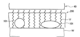
- the ultrasonic wave U is propagated through several layers of water molecules 102.
- the sound pressure applied to the particles 101 can be increased to, for example, about 1 ⁇ 10 6 Pa at the maximum. That is, by adhering several layers of water molecules 102 to the surface of the wafer W, an ultrasonic generator that is normally used in the dry cleaning method is used to generate a larger sound pressure than in the dry cleaning method. It becomes possible to add to.
- the cleaning method of the present embodiment the particles 101 existing on the surface of the wafer W can be effectively peeled and efficiently removed from the surface of the wafer W.
- the gas whose concentration is adjusted in the processing container 1 by the gas introduction device 20 is introduced, and the gas concentration in the processing container 1 is adjusted.
- ultrasonic cleaning can be performed in a state where gas molecules having a thickness of several molecular layers are attached to the surface of the wafer W.
- particles on the surface of the wafer W can be effectively removed without causing pattern collapse or material loss due to ultrasonic waves.
- the present invention is not limited to a case where a semiconductor wafer is used as an object to be processed, and can be applied to a case where, for example, a solar cell panel substrate or a flat panel display substrate is used as an object to be processed.
- the gas introduction device 20 is not limited to the bubbling vaporizer 22 having the configuration shown in FIG. 1 as long as it can generate a gas having a predetermined concentration.
Landscapes
- Cleaning Or Drying Semiconductors (AREA)
- Cleaning By Liquid Or Steam (AREA)
Abstract
洗浄装置(100)は、内部を密閉することができる処理容器(1)と、処理容器(1)内に設けられた、被処理体であるウエハ(W)を保持するスピンチャック(10)と、処理容器(1)内へ濃度調節されたガスを導入するガス導入装置(20)と、処理容器(1)内のガス濃度を検出する検出装置としてのガス濃度センサ(30)と、超音波を発生させ、スピンチャック(10)に保持されたウエハ(W)の表面に超音波を伝搬させる超音波発生装置(40)と、を備えている。
Description
本発明は、例えば半導体装置などの製造工程で基板を洗浄するための基板洗浄装置及び基板洗浄方法に関する。
半導体装置などの製造工程においては、半導体ウエハなどの基板の洗浄が行われる。従来は、複数枚の基板を大型の浸漬槽に浸漬して洗浄するディップ式洗浄が行なわれてきた。しかし、基板サイズの大口径化に伴って、近年では枚葉式のスピン洗浄が主流になりつつある(例えば、日本国特開2009-71272号公報)。枚葉式のスピン洗浄は、大径の基板についても面内を均一に洗浄できることや、洗浄によって除去した汚染物質の再付着が少ないこと、洗浄液やリンス用純水の使用量を抑制できること等の利点がある。
スピン洗浄方式の基板洗浄には、超音波が広く利用されている。これは、洗浄チャンバ内で基板を回転させながら、基板表面に超音波ノズルから洗浄液を吐出するとともに、超音波ノズルに内蔵されている超音波振動子を発振させる。そして、洗浄液の液膜を介して基板表面に超音波を伝搬させ、超音波の振動エネルギーと遠心力による液体の衝突などの物理力を利用して基板表面の洗浄を行う。基板表面に吐出された洗浄液は、基板の回転に伴う遠心力によって、超音波振動で剥離したパーティクルを伴って基板の径外方向へと移動し、基板の周縁部から洗浄チャンバ内に流出する。
ところで、近年、半導体装置の微細化が進んでおり、微細パターンが形成された基板に対する洗浄が求められている。しかし、微細パターンを有する基板に対してスピン洗浄を行うと、超音波の音圧が強過ぎることによって、基板表面に形成したパターンを破壊する場合がある。
また、超音波方式と同じく従来広く利用されている方式として2流体スプレー方式が知られている。この2流体スプレー方式では、スプレーノズルから微小な液滴を発生させて基板に衝突させる事でパーティクルを除去しているが、50nm以下の微少なパーティクルを除去する事が難しい。これは、基板と水の境界付近では水の流れがほとんど発生せず、パーティクル除去に効果的な力を与える事が出来ないためである。加えて、純水を使用することで基板表面の水溶性材料の溶解によるマテリアルロスが生じること、洗浄後の乾燥工程で大量のイソプロピルアルコールが必要になること、などの問題もあった。
本発明は、超音波を利用して基板表面のパーティクルを効果的に除去できる基板洗浄装置及び基板洗浄方法を提供する。
本発明の基板洗浄装置は、基板を収容する処理容器と、前記処理容器内で基板を回転可能に保持する基板保持装置と、前記処理容器内に、濃度調節されたガスを導入するガス導入装置と、前記処理容器内のガス濃度を検出する検出装置と、超音波を発生させ、前記基板保持装置に保持された基板の表面に超音波を伝搬させる超音波発生装置と、を備えている。そして、本発明の基板洗浄装置は、前記ガス導入装置によって前記処理容器内に濃度調節されたガスを導入し、前記処理容器内のガス濃度を調節しながら、前記超音波発生装置によって発生させた超音波によって基板の洗浄を行う。
また、本発明の基板洗浄装置は、さらに、前記基板を冷却する冷却装置を備えていてもよい。
また、本発明の基板洗浄装置において、前記ガス導入装置は、液体を気化させる気化装置と、気化したガスを所定流量で前記処理容器内へ供給する流量調節装置と、を有していてもよい。
また、本発明の基板洗浄装置は、前記濃度調節されたガスが、水分を含む空気であってもよい。
また、本発明の基板洗浄装置は、さらに、前記検出装置によって検出されたガス濃度に基づき、前記ガス導入装置によって前記処理容器内に導入するガスの濃度及び/又は流量を調節する制御部を備えていてもよい。
本発明の基板洗浄方法は、超音波発生装置によって発生させた超音波を利用して基板の洗浄を行うものであって、処理容器内に基板を搬入し、基板保持装置によって回転可能に保持する工程と、前記処理容器内に濃度調節されたガスを導入し、処理容器内のガス濃度を調整する工程と、前記基板保持装置に保持された基板を回転させながら、超音波発生装置によって発生させた超音波を基板の表面に付与し、基板表面において超音波を伝搬させることによって基板の洗浄を行う工程と、を備えている。
また、本発明の基板洗浄方法は、前記基板を洗浄する工程より前に、さらに、基板を冷却する工程を備えていてもよい。
また、本発明の基板洗浄方法は、前記基板の洗浄を行う工程の間、前記基板の冷却を継続してもよい。
また、本発明の基板洗浄方法は、前記濃度調節されたガスが、水分を含む空気であってもよい。この場合、前記処理容器内の水分濃度は、装置内雰囲気温度における飽和水蒸気量未満であることが望ましい。
本発明では、ガス導入装置によって処理容器内に濃度調節されたガスを導入し、処理容器内のガス濃度を調節することによって、基板の表面に、数分子層の厚みでガス分子を付着させた状態で超音波洗浄を行う。これによって、超音波によるパターン崩れやマテリアルロスを発生させることなく、基板表面のパーティクルを効果的に除去できる。
以下、図面を参照して本発明の実施の形態について説明する。
[洗浄装置の概要]
まず、本発明の一実施の形態に係る洗浄装置の構成例について説明する。図1は、本実施の形態にかかる洗浄装置100の概略構成を示す縦断面図である。洗浄装置100は、内部を密閉することができる処理容器1と、処理容器1内に設けられた、被処理体である半導体ウエハ(以下、単に「ウエハ」という)Wを保持する基板保持装置としてのスピンチャック10とを備えている。また、洗浄装置100は、処理容器1内へ濃度調節されたガスを導入するガス導入装置20と、処理容器1内のガス濃度を検出する検出装置としてのガス濃度センサ30と、を備えている。また、洗浄装置100は、超音波を発生させ、スピンチャック10に保持されたウエハWの表面に超音波を伝搬させる超音波発生装置40と、ウエハWを冷却する冷却装置50と、を備えている。さらに、洗浄装置100は、洗浄装置100における各構成部を制御する制御部60を備えている。
まず、本発明の一実施の形態に係る洗浄装置の構成例について説明する。図1は、本実施の形態にかかる洗浄装置100の概略構成を示す縦断面図である。洗浄装置100は、内部を密閉することができる処理容器1と、処理容器1内に設けられた、被処理体である半導体ウエハ(以下、単に「ウエハ」という)Wを保持する基板保持装置としてのスピンチャック10とを備えている。また、洗浄装置100は、処理容器1内へ濃度調節されたガスを導入するガス導入装置20と、処理容器1内のガス濃度を検出する検出装置としてのガス濃度センサ30と、を備えている。また、洗浄装置100は、超音波を発生させ、スピンチャック10に保持されたウエハWの表面に超音波を伝搬させる超音波発生装置40と、ウエハWを冷却する冷却装置50と、を備えている。さらに、洗浄装置100は、洗浄装置100における各構成部を制御する制御部60を備えている。
この洗浄装置100は、ガス導入装置20によって処理容器1内に濃度調節されたガスを導入し、処理容器1内のガス濃度を調節しながら、超音波発生装置40によって発生させた超音波によってウエハWの洗浄を行うものである。
(処理容器)
処理容器1は、天板1a、側壁1b及び底壁1cを備えている。処理容器1は、例えばアルミニウム、SUSなどの材質で形成されている。処理容器1の一側面には、図示を省略するが、ウエハWの搬入出口が形成され、該搬入出口には、開閉シャッタが設けられている。
処理容器1は、天板1a、側壁1b及び底壁1cを備えている。処理容器1は、例えばアルミニウム、SUSなどの材質で形成されている。処理容器1の一側面には、図示を省略するが、ウエハWの搬入出口が形成され、該搬入出口には、開閉シャッタが設けられている。
(スピンチャック)
処理容器1の内部には、図1に示すようにウエハWを吸着保持する回転保持部材として、スピンチャック10が設けられている。スピンチャック10は、水平な上面を有し、当該上面には、例えばウエハWを吸引する吸引口(図示せず)が設けられている。この吸引口からの吸引によって、ウエハWをスピンチャック10上に吸着保持できる。
処理容器1の内部には、図1に示すようにウエハWを吸着保持する回転保持部材として、スピンチャック10が設けられている。スピンチャック10は、水平な上面を有し、当該上面には、例えばウエハWを吸引する吸引口(図示せず)が設けられている。この吸引口からの吸引によって、ウエハWをスピンチャック10上に吸着保持できる。
スピンチャック10は、支柱10aを介して駆動部11に接続されている。駆動部11は、例えばモータなどの回転駆動部を有しており、支柱10aを回転させることによって、スピンチャック10に保持されたウエハWを所定の速度で水平方向に回転できる。また、駆動部11は、例えばシリンダなどの昇降駆動部を有しており、支柱10aを含むスピンチャック10を上下に昇降変位させることができる。
スピンチャック10の下方側にはガイドリング12が設けられており、このガイドリング12の外周縁は下方側に折曲して延びている。また、スピンチャック10、このスピンチャック10に保持されたウエハW及びガイドリング12を囲むように、これらの外側にカップ13が設けられている。カップ13によって、ウエハWから飛散又は落下するパーティクルを受け止め、回収することができる。
このカップ13の上部には、ウエハWを保持した状態のスピンチャック10が昇降できるように、ウエハWよりも大きい開口部13aが形成されている。また、カップ13の内側周面とガイドリング12の折曲した外周縁との間には、排出路となる隙間14が形成されている。カップ13の下部は、ガイドリング12の外周縁部分と共に屈曲路を形成して気液分離部を構成している。カップ13の底部の内側領域には、カップ13内の雰囲気を排気する排気口15が形成されており、この排気口15には排気管15aが接続されている。さらに、前記カップ13の底部の外側領域には、回収した液体を排出する排液口16が形成されており、この排液口16には排液管16aが接続されている。
(ガス導入装置)
ガス導入装置20は、処理容器1内へ濃度調節されたガスを導入する。ガス導入装置20は、キャリアガス源21と、該キャリアガス源21からのキャリアガスを導入しながら液体を気化させる気化装置22と、キャリアガス源21と気化装置22との間を接続する配管23と、該配管23に設けられたバルブ24と、を有している。また、ガス導入装置20は、気化装置22で気化したガスを処理容器1内に供給する配管25と、配管25に設けられ、供給するガスの流量調節を行う流量調節装置(マスフローコントローラ(MFC))26と、配管25に設けられたバルブ27と、を有している。さらに、ガス導入装置20は、配管25によって処理容器1の側壁1bに設けられたガス導入口28に接続されている。なお、洗浄装置100は、ガス導入装置20以外のガス導入機構として、例えば、処理容器1内をパージするためのパージガス導入装置などを有していてもよい。ガス導入装置20によって処理容器1内へ導入するガスとしては、例えば、水分を含有する空気、水分を含有する窒素ガス、メタノールなどの有機溶媒を挙げることができる。
ガス導入装置20は、処理容器1内へ濃度調節されたガスを導入する。ガス導入装置20は、キャリアガス源21と、該キャリアガス源21からのキャリアガスを導入しながら液体を気化させる気化装置22と、キャリアガス源21と気化装置22との間を接続する配管23と、該配管23に設けられたバルブ24と、を有している。また、ガス導入装置20は、気化装置22で気化したガスを処理容器1内に供給する配管25と、配管25に設けられ、供給するガスの流量調節を行う流量調節装置(マスフローコントローラ(MFC))26と、配管25に設けられたバルブ27と、を有している。さらに、ガス導入装置20は、配管25によって処理容器1の側壁1bに設けられたガス導入口28に接続されている。なお、洗浄装置100は、ガス導入装置20以外のガス導入機構として、例えば、処理容器1内をパージするためのパージガス導入装置などを有していてもよい。ガス導入装置20によって処理容器1内へ導入するガスとしては、例えば、水分を含有する空気、水分を含有する窒素ガス、メタノールなどの有機溶媒を挙げることができる。
ガス導入装置20によって、処理容器1内へ濃度調節されたガスを導入することによって、処理容器1内のガス濃度を厳密に管理することができる。また、処理容器1内のガス濃度は、処理容器1の側壁1bを介して内部雰囲気に露出するように装着されたガス濃度センサ30によって検出することができる。例えば、ガス導入装置20によって処理容器1内へ導入されるガスが、水分を含有する空気又は水分を含有する窒素ガスの場合、ガス濃度センサ30としては湿度計が用いられる。
(超音波発生装置)
超音波発生装置40は、超音波を発生させ、スピンチャック10に保持されたウエハWの表面に超音波を付与し、伝搬させる。超音波発生装置40は、図示しない振動子を備えた超音波付与ヘッド41と、超音波付与ヘッド41を保持するアーム部材42と、超音波付与ヘッド41を移動させるヘッド駆動部43と、超音波付与ヘッド41に向けてパルス信号を出力する超音波発振器44と、を有している。ヘッド駆動部43は、超音波付与ヘッド41とウエハWの表面との距離を一定に保ちながら、超音波付与ヘッド41をウエハWに対して相対移動させる。超音波発振器44は、制御部60からの制御信号に基づき、パルス信号を超音波付与ヘッド41の振動子(図示せず)に出力する。これによって、振動子が超音波振動し、ウエハW表面に超音波振動が付与される。本実施の形態では、気相中で使用するため、超音波付与ヘッド41として増幅設備(例えばホーン)を有するものや、熱伝搬方式の振動子を有するものなどを用いることが好ましい。
超音波発生装置40は、超音波を発生させ、スピンチャック10に保持されたウエハWの表面に超音波を付与し、伝搬させる。超音波発生装置40は、図示しない振動子を備えた超音波付与ヘッド41と、超音波付与ヘッド41を保持するアーム部材42と、超音波付与ヘッド41を移動させるヘッド駆動部43と、超音波付与ヘッド41に向けてパルス信号を出力する超音波発振器44と、を有している。ヘッド駆動部43は、超音波付与ヘッド41とウエハWの表面との距離を一定に保ちながら、超音波付与ヘッド41をウエハWに対して相対移動させる。超音波発振器44は、制御部60からの制御信号に基づき、パルス信号を超音波付与ヘッド41の振動子(図示せず)に出力する。これによって、振動子が超音波振動し、ウエハW表面に超音波振動が付与される。本実施の形態では、気相中で使用するため、超音波付与ヘッド41として増幅設備(例えばホーン)を有するものや、熱伝搬方式の振動子を有するものなどを用いることが好ましい。
(冷却装置)
冷却装置50は、ノズル51A,51Bと、ノズル51A,51Bへ冷媒を供給する冷媒源52と、ノズル51A,51Bと冷媒源52とを接続する冷媒供給管53A,53Bと、を備えている。ノズル51Aは、ウエハWの周縁部の裏面に冷媒を供給できるように配置されている。ノズル51Bは、支柱10a内に挿通された冷媒供給管53Bを介してウエハWの中央部の裏面に向けて冷媒を供給できるように配備されている。冷却装置50は、冷媒源52から所定温度に冷却された冷媒を供給し、ノズル51A,51BからウエハWの裏面に噴射することによって、ウエハWを冷却することができる。ここで、冷媒としては、例えばHeガス、CO2ガスなどを用いることができる。なお、ウエハWの冷却は、例えばチラー機構などによって行ってもよい。
冷却装置50は、ノズル51A,51Bと、ノズル51A,51Bへ冷媒を供給する冷媒源52と、ノズル51A,51Bと冷媒源52とを接続する冷媒供給管53A,53Bと、を備えている。ノズル51Aは、ウエハWの周縁部の裏面に冷媒を供給できるように配置されている。ノズル51Bは、支柱10a内に挿通された冷媒供給管53Bを介してウエハWの中央部の裏面に向けて冷媒を供給できるように配備されている。冷却装置50は、冷媒源52から所定温度に冷却された冷媒を供給し、ノズル51A,51BからウエハWの裏面に噴射することによって、ウエハWを冷却することができる。ここで、冷媒としては、例えばHeガス、CO2ガスなどを用いることができる。なお、ウエハWの冷却は、例えばチラー機構などによって行ってもよい。
(制御部)
洗浄装置100を構成する各エンドデバイス(例えば、スピンチャック10、ガス導入装置20、ガス濃度センサ30、超音波発生装置40、冷却装置50など)は、制御部60に接続されて制御される構成となっている。コンピュータ機能を有する制御部60は、CPUを備えたコントローラ61と、このコントローラ61に接続されたユーザーインターフェース62および記憶部63を備えている。ユーザーインターフェース62は、工程管理者が洗浄装置100を管理するためにコマンドの入力操作等を行うキーボードやタッチパネル、洗浄装置100の稼働状況を可視化して表示するディスプレイ等を有している。記憶部63には、洗浄装置100で実行される各種処理をコントローラ61の制御にて実現するための制御プログラム(ソフトウェア)や処理条件データ等が記録されたレシピが保存されている。そして、必要に応じて、ユーザーインターフェース62からの指示等にて任意の制御プログラムやレシピを記憶部63から呼び出してコントローラ61に実行させることで、コントローラ61の制御下で、洗浄装置100の処理容器1内で所望の洗浄処理が行われる。
洗浄装置100を構成する各エンドデバイス(例えば、スピンチャック10、ガス導入装置20、ガス濃度センサ30、超音波発生装置40、冷却装置50など)は、制御部60に接続されて制御される構成となっている。コンピュータ機能を有する制御部60は、CPUを備えたコントローラ61と、このコントローラ61に接続されたユーザーインターフェース62および記憶部63を備えている。ユーザーインターフェース62は、工程管理者が洗浄装置100を管理するためにコマンドの入力操作等を行うキーボードやタッチパネル、洗浄装置100の稼働状況を可視化して表示するディスプレイ等を有している。記憶部63には、洗浄装置100で実行される各種処理をコントローラ61の制御にて実現するための制御プログラム(ソフトウェア)や処理条件データ等が記録されたレシピが保存されている。そして、必要に応じて、ユーザーインターフェース62からの指示等にて任意の制御プログラムやレシピを記憶部63から呼び出してコントローラ61に実行させることで、コントローラ61の制御下で、洗浄装置100の処理容器1内で所望の洗浄処理が行われる。
具体的には、コントローラ61は、上記各エンドデバイスに対し、レシピに定められた条件で作動や停止を指示する。例えば、コントローラ61は、処理容器1内のガス濃度をレシピに基づく範囲に保持するため、ガス導入装置20に制御信号を送出し、作動や停止を指示するほか、処理容器1内に導入するガスの流量や濃度を調節する。この場合、コントローラ61は、ガス濃度センサ30によって検出された処理容器1内のガス濃度の検出値の信号を参照し、ガス供給装置20に対しフィードバック制御を行うこともできる。また、コントローラ61は、スピンチャック10、超音波発生装置40、冷却装置50などに対しても、制御信号を送出し、作動や停止を指示するほか、ガス濃度センサ30によって検出された処理容器1内のガス濃度の検出値の信号を参照しながら、これらのエンドデバイスを制御することができる。例えば、コントローラ61は、ガス濃度センサ30によって検出された処理容器1内のガス濃度の検出値に応じて、超音波発生装置40によって発生させる超音波の発振周波数や振動振幅などを調節することができる。また、コントローラ61は、ガス濃度センサ30によって検出された処理容器1内のガス濃度の検出値に応じて、駆動部11に制御信号を送出し、スピンチャック10の回転速度を調節することもできる。さらに、コントローラ61は、ガス濃度センサ30によって検出された処理容器1内のガス濃度の検出値に応じて、冷却装置50によるウエハWの冷却温度を調節するため、冷媒の温度や噴射量などを調節することもできる。
前記制御プログラムや処理条件データ等のレシピは、コンピュータ読み取り可能な記録媒体64に格納された状態のものを記憶部63にインストールすることによって利用できる。コンピュータ読み取り可能な記録媒体64としては、特に制限はないが、例えばCD-ROM、ハードディスク、フレキシブルディスク、フラッシュメモリ、DVDなどを使用できる。また、前記レシピは、他の装置から、例えば専用回線を介して随時伝送させてオンラインで利用したりすることも可能である。
[洗浄方法]
洗浄装置100では、ウエハWに対して超音波発生装置40によって発生させた超音波を利用した洗浄処理が行われる。洗浄装置100における洗浄処理は、例えば、処理容器1内にウエハWを搬入し、スピンチャック10によって回転可能に保持する工程と、処理容器1内にガスを導入し、処理容器1内のガス濃度を調節する工程と、ウエハWを回転させながら、超音波発生装置40によって超音波を発生させ、スピンチャック10に保持されたウエハWの表面に超音波を伝搬させることによってウエハWの洗浄を行う工程と、を含むことができる。以下、各工程について説明する。
洗浄装置100では、ウエハWに対して超音波発生装置40によって発生させた超音波を利用した洗浄処理が行われる。洗浄装置100における洗浄処理は、例えば、処理容器1内にウエハWを搬入し、スピンチャック10によって回転可能に保持する工程と、処理容器1内にガスを導入し、処理容器1内のガス濃度を調節する工程と、ウエハWを回転させながら、超音波発生装置40によって超音波を発生させ、スピンチャック10に保持されたウエハWの表面に超音波を伝搬させることによってウエハWの洗浄を行う工程と、を含むことができる。以下、各工程について説明する。
(ウエハの搬入及び固定)
まず、処理容器1の図示しない搬入出口を開放した状態で、外部の搬送装置によってウエハWを搬入する。スピンチャック10は、上記のとおり駆動部11によって昇降変位が可能に構成されており、上昇位置において外部の搬送装置との間でウエハWの受け渡しを行う。次に、スピンチャック10にウエハWを保持した状態で下降させ、洗浄位置にセットする。
まず、処理容器1の図示しない搬入出口を開放した状態で、外部の搬送装置によってウエハWを搬入する。スピンチャック10は、上記のとおり駆動部11によって昇降変位が可能に構成されており、上昇位置において外部の搬送装置との間でウエハWの受け渡しを行う。次に、スピンチャック10にウエハWを保持した状態で下降させ、洗浄位置にセットする。
(ガス濃度の調整)
次に、ガス導入装置20によって処理容器1内へ所定濃度のガスを導入する。すなわち、配管23のバルブ24及び配管25のバルブ27を開放し、キャリアガス源21からキャリアガスを気化装置22に導入する。そして、気化装置22で気化されたガスをマスフローコントローラ26で流量調節しながら、ガス導入口28を介して処理容器1内へ供給する。キャリアガスとしては、例えば、乾燥エア、乾燥窒素ガスなどを用いることができる。また、気化装置22に貯留され、気化対象となる液体としては、例えば蒸留水、有機溶媒などを挙げることができる。
次に、ガス導入装置20によって処理容器1内へ所定濃度のガスを導入する。すなわち、配管23のバルブ24及び配管25のバルブ27を開放し、キャリアガス源21からキャリアガスを気化装置22に導入する。そして、気化装置22で気化されたガスをマスフローコントローラ26で流量調節しながら、ガス導入口28を介して処理容器1内へ供給する。キャリアガスとしては、例えば、乾燥エア、乾燥窒素ガスなどを用いることができる。また、気化装置22に貯留され、気化対象となる液体としては、例えば蒸留水、有機溶媒などを挙げることができる。
ガスの導入開始後、例えば10秒以上300秒以下の間ガスの供給を続けることで、処理容器1内のガス濃度を安定化させる。例えば、ガスとして、水分を含有する空気又は水分を含有する窒素ガスを用いる場合、ウエハW表面に適量の水分子を付着させる観点から、処理容器1内の湿度が例えば0.1%以上、処理容器1内の雰囲気温度における飽和水蒸気量未満となるように調節することが好ましい。処理容器1内の湿度が0.1%未満では、ウエハW表面への水分子の高効率な付着が困難であり、飽和水蒸気量以上であると、ウエハW表面に過剰量の水分子が付着し、液膜が形成されてしまう。なお、本実施の形態では、処理容器1内の圧力に関しては特段の制御は必要でなく、大気圧が好ましい。
(超音波洗浄処理)
次に、駆動部11を駆動させ、スピンチャック10によって保持したウエハWを所定速度で回転させながら、超音波発生装置40によって超音波を発生させ、スピンチャック10に保持されたウエハWの表面に超音波を伝搬させることによってウエハWの洗浄を行う。具体的には、超音波発振器44から超音波付与ヘッド41に向けてパルス信号を出力してウエハWの表面に超音波振動を付与する。この間、ヘッド駆動部43によってアーム部材42を動かし、超音波付与ヘッド41を回転するウエハWの径方向にスキャンさせる。
次に、駆動部11を駆動させ、スピンチャック10によって保持したウエハWを所定速度で回転させながら、超音波発生装置40によって超音波を発生させ、スピンチャック10に保持されたウエハWの表面に超音波を伝搬させることによってウエハWの洗浄を行う。具体的には、超音波発振器44から超音波付与ヘッド41に向けてパルス信号を出力してウエハWの表面に超音波振動を付与する。この間、ヘッド駆動部43によってアーム部材42を動かし、超音波付与ヘッド41を回転するウエハWの径方向にスキャンさせる。
超音波洗浄処理において、超音波付与ヘッド41からウエハW表面に付与する超音波の振動周波数は、ウエハWの表面における音圧を好ましくは1×10⁴Pa以上1×10⁶Pa以下の範囲内に制御する観点から、例えば20kHz以上1.6MHz以下の範囲内とすることが好ましい。
また、ウエハWの回転速度は、超音波によって剥離されたパーティクルを遠心力によってウエハWの径外方向に効率良く飛散させる観点から、例えば100rpm以上1000rpm以下の範囲内とすることが好ましい。
ここで、本実施の形態の洗浄方法において、ガス導入装置20を用いて処理容器1内のガス濃度を制御しながら超音波洗浄処理を施す意義について図2~図5Bを参照して説明する。図2~図4は、本実施の形態の洗浄方法によって生じるウエハW表面の状態変化を説明する模式図である。ここでは、所定濃度の水分を含む空気を処理容器1内に導入する場合を例に挙げて説明する。図5A,図5Bは、比較例の洗浄方法におけるウエハWの表面状態を説明する模式図である。
図2は、洗浄前の状態を示している。この状態では、処理容器1内の湿度の調整は行っていない。ウエハWの表面には、複数の微細なパーティクル101が付着している。次に、図3は、ウエハWの表面に水分子102が付着した状態を示している。この状態は、ウエハWの表面に数層、例えば5層以下、好ましくは2~3分子層程度の水分子102が付着している程度であり、液膜が生成した状態(完全に濡れた状態)とは異なる。目視では乾燥状態と区別できない程度の付着量である。このように、ウエハWの表面に数層の水分子102が付着した状態は、ガス導入装置20によって処理容器1内へ所定濃度の水分を含む空気を導入し、処理容器1内の湿度を上記範囲内に制御することによって作り出すことができる。
次に、図4に示すように、超音波発生装置40によって超音波Uを発生させ、超音波付与ヘッド41から、スピンチャック10に保持されたウエハWの表面に超音波を伝搬させる。本実施の形態では、数層の水分子102を介して超音波Uを伝搬させることによって、図4に示すように、超音波振動による物理力でウエハWの表面に存在するパーティクル101を効果的に剥離させ、ウエハWの表面から除去することができる。ウエハWから回転の遠心力で飛散又は落下したパーティクル101は、カップ13によって受け止められ、隙間14を介してカップ13の底部に落下する。落下したパーティクルは、カップ13の内部を水などで洗い流すことによって、排液口16から回収することができる。
超音波洗浄の時間は、特に限定されるものではないが、例えば1分間以上10分間以下の範囲内とすることができる。
(ウエハの搬出)
所定時間の超音波洗浄が終了したら、超音波発生装置40及びスピンチャック10の回転を停止し、スピンチャック10とともにウエハWを受け渡し位置まで上昇させる。そして、外部の搬送装置を用い、上記と逆の手順でウエハWを処理容器1内から搬出することによって、1枚のウエハWに関する洗浄処理が完了する。
所定時間の超音波洗浄が終了したら、超音波発生装置40及びスピンチャック10の回転を停止し、スピンチャック10とともにウエハWを受け渡し位置まで上昇させる。そして、外部の搬送装置を用い、上記と逆の手順でウエハWを処理容器1内から搬出することによって、1枚のウエハWに関する洗浄処理が完了する。
(任意工程)
本実施の形態の洗浄方法は、上記以外の任意の工程を含むことができる。例えば、ウエハWを洗浄する工程より前に、ウエハWを冷却する工程を設けることが好ましい。ウエハWの冷却は、冷却装置50の冷媒源52から冷媒例えば所定温度に冷却されたHeガスなどを供給し、ノズル51A及び/又はノズル51Bを介してウエハWの裏面に噴射することによって行うことができる。超音波洗浄時のウエハWの温度は、例えば0℃以上200℃以下の範囲内であればよいが、本工程でウエハWの冷却を行う場合は、例えば、処理容器1内の雰囲気温度から10℃程度低い温度までの範囲内に冷却することが好ましい。このように、ウエハWを処理容器1内の雰囲気温度よりも低い温度に冷却しておくことによって、ガス中に含まれる分子(例えば水分子)がウエハW表面に付着しやすくなり、数層の厚みのガス分子をウエハW表面に効率よく形成することができる。また、超音波発生装置40によってウエハWに対して超音波を付与している間、冷却装置50によるウエハWの冷却を継続して行うことが好ましい。
本実施の形態の洗浄方法は、上記以外の任意の工程を含むことができる。例えば、ウエハWを洗浄する工程より前に、ウエハWを冷却する工程を設けることが好ましい。ウエハWの冷却は、冷却装置50の冷媒源52から冷媒例えば所定温度に冷却されたHeガスなどを供給し、ノズル51A及び/又はノズル51Bを介してウエハWの裏面に噴射することによって行うことができる。超音波洗浄時のウエハWの温度は、例えば0℃以上200℃以下の範囲内であればよいが、本工程でウエハWの冷却を行う場合は、例えば、処理容器1内の雰囲気温度から10℃程度低い温度までの範囲内に冷却することが好ましい。このように、ウエハWを処理容器1内の雰囲気温度よりも低い温度に冷却しておくことによって、ガス中に含まれる分子(例えば水分子)がウエハW表面に付着しやすくなり、数層の厚みのガス分子をウエハW表面に効率よく形成することができる。また、超音波発生装置40によってウエハWに対して超音波を付与している間、冷却装置50によるウエハWの冷却を継続して行うことが好ましい。
[作用]
次に、比較例の洗浄方法との対比において、本発明の作用効果について説明する。図5Aは、ウエハWの表面に多量の水200が存在する状態で超音波洗浄を行う場合を示している。例えば、ウエハWを水中に浸漬するディップ方式、あるいは、スピンチャック10に固定したウエハWの表面に水200を滴下しながら、厚さ数mm程度の液膜を形成した状態で超音波Uを付与するスピン洗浄方式を挙げることができる。図5BはウエハWの表面が完全に乾燥した状態で超音波洗浄を行うドライ洗浄方式を示している。
次に、比較例の洗浄方法との対比において、本発明の作用効果について説明する。図5Aは、ウエハWの表面に多量の水200が存在する状態で超音波洗浄を行う場合を示している。例えば、ウエハWを水中に浸漬するディップ方式、あるいは、スピンチャック10に固定したウエハWの表面に水200を滴下しながら、厚さ数mm程度の液膜を形成した状態で超音波Uを付与するスピン洗浄方式を挙げることができる。図5BはウエハWの表面が完全に乾燥した状態で超音波洗浄を行うドライ洗浄方式を示している。
図5Aに示したように、水中で超音波振動を伝搬させる方式(以下、「ウェット洗浄方式」と記すことがある)では、超音波発生装置として、ウエハWの表面での音圧が例えば1×10⁵~5×10⁵Pa程度の大きさとなるものを使用できるため、大きな物理力によってパーティクル101の除去効率が高い。このような超音波発生装置の例として、本多電子株式会社製石英振動体型洗浄機(型式W-357-1MQB-CV)などを挙げることができる。
しかし、上述のように、ウェット洗浄方式はウエハW表面に形成されたパターンへのダメージが大きく、水溶性材料の溶出によるマテリアルロスが問題となる。
一方、図5Bに示したようなドライ洗浄方式の場合は、超音波発生装置として、振動子の後段に増幅設備(ホーン)を備えたものや、熱伝搬方式の振動子を有するものを使用する。この場合、ウエハWの表面での音圧は例えば2×10²Pa程度に留まるため、パーティクル101の除去効率が十分に得られないという問題がある。なお、ウェット洗浄方式で使用される大きな音圧を発生できる超音波発生装置(例えば、上記の本多電子株式会社製石英振動体型洗浄機(型式W-357-1MQB-CV))は、空気中では振動子が異常加熱してしまうためドライ洗浄方式では使用できない。
超音波振動によって発生する音圧の大きさは、ウエハW表面の分子密度に依存する。図5A及び図5Bに示した比較例の洗浄方法に対し、本実施の形態の洗浄方法では、図4に示したように、数層の水分子102を介して超音波Uを伝搬させることによって、パーティクル101に与えられる音圧を例えば最大で1×10⁶Pa程度まで増加させることが可能になる。つまり、ウエハWの表面に数層の水分子102を付着させておくことによって、通常ドライ洗浄方式で使用される超音波発生装置を用いて、ドライ洗浄方式の場合より大きな音圧をウエハW表面に加えることが可能になる。また、この程度の音圧であれば、ウェット洗浄方式のようなパターンへのダメージの問題は生じず、水分量も少ないため、マテリアルロスも生じない。このような原理によって、本実施の形態の洗浄方法では、ウエハWの表面に存在するパーティクル101を効果的に剥離させ、ウエハWの表面から効率良く除去することができる。
なお、処理容器1内の湿度の調整によってウエハW表面に付着させた水分子層の厚み(層数N)は、以下の手順で計測することができる。まず、ウエハWの表面に水分子が付着した状態で全体の重量を測定する。次に、付着した水分を加熱脱離させた状態でウエハWの重量を測定する。そして、水分子の加熱脱離の前後のウエハWの重量変化から付着水分の重量を算出する。次に、ウエハWの表面に1層の水分子が規則的に配列した状態を仮定し、その時の分子量Mを計算によって求める。また、上記計測された付着水分の重量から、計算によって分子量M1を求める。そして、ウエハW表面に付着させた水分子層の厚み(層数N)は、次の式;N=M1/M、によって算出することができる。
以上のように、本実施の形態の洗浄装置100及び洗浄方法によれば、ガス導入装置20によって処理容器1内に濃度調節されたガスを導入し、処理容器1内のガス濃度を調節することによって、ウエハWの表面に数分子層の厚みのガス分子を付着させた状態で超音波洗浄を行うことができる。これによって、超音波によるパターン崩れやマテリアルロスを発生させることなく、ウエハW表面のパーティクルを効果的に除去できる。
以上、本発明の実施の形態を例示の目的で詳細に説明したが、本発明は上記実施の形態に制約されることはなく、種々の変形が可能である。例えば、本発明は、半導体ウエハを被処理体とする場合に限らず、例えば太陽電池パネル用基板やフラットパネルディスプレイ用基板を被処理体とする場合にも適用できる。
また、ガス導入装置20は、所定濃度のガスを生成できればよいため、図1に示した構成のバブリング方式の気化装置22に限らず、例えばノズルから噴射して気化させる方式などでもよい。
本国際出願は、2012年9月26日に出願された日本国特許出願2012-212271号に基づく優先権を主張するものであり、この出願の全内容をここに援用する。
Claims (10)
- 基板を収容する処理容器と、
前記処理容器内で前記基板を回転可能に保持する基板保持装置と、
前記処理容器内に、濃度調節されたガスを導入するガス導入装置と、
前記処理容器内のガス濃度を検出する検出装置と、
超音波を発生させ、前記基板保持装置に保持された前記基板の表面に超音波を伝搬させる超音波発生装置と、
を備え、前記ガス導入装置によって前記処理容器内に濃度調節されたガスを導入し、前記処理容器内の前記ガスの濃度を調節しながら、前記超音波発生装置によって発生させた超音波によって、前記基板の洗浄を行う基板洗浄装置。 - さらに、前記基板を冷却する冷却装置を備えている請求項1に記載の基板洗浄装置。
- 前記ガス導入装置は、液体を気化させる気化装置と、気化した前記ガスを所定流量で前記処理容器内へ供給する流量調節装置と、を有している請求項1に記載の基板洗浄装置。
- 前記濃度調節された前記ガスが、水分を含む空気である請求項1に記載の基板洗浄装置。
- さらに、前記検出装置によって検出された前記ガスの濃度に基づき、前記ガス導入装置によって前記処理容器内に導入する前記ガスの濃度及び/又は流量を調節する制御部を備えた請求項1に記載の基板洗浄装置。
- 超音波発生装置によって発生させた超音波を利用して基板の洗浄を行う基板洗浄方法であって、
処理容器内に前記基板を搬入し、基板保持装置によって回転可能に保持する工程と、
前記処理容器内に濃度調節されたガスを導入し、処理容器内の前記ガスの濃度を調整する工程と、
前記基板保持装置に保持された前記基板を回転させながら、超音波発生装置によって発生させた超音波を前記基板の表面に付与し、前記基板の表面において超音波を伝搬させることによって前記基板の洗浄を行う工程と、
を備えた基板洗浄方法。 - 前記基板の洗浄を行う工程より前に、さらに、前記基板を冷却する工程を備えている請求項6に記載の基板洗浄方法。
- 前記基板の洗浄を行う工程の間、前記基板の冷却を継続する、請求項7に記載の基板洗浄方法。
- 前記濃度調節されたガスが、水分を含む空気である請求項6に記載の基板洗浄方法。
- 前記処理容器内の湿度が、前記処理容器内の雰囲気温度における飽和水蒸気量未満である請求項9に記載の基板洗浄方法。
Applications Claiming Priority (2)
| Application Number | Priority Date | Filing Date | Title |
|---|---|---|---|
| JP2012-212271 | 2012-09-26 | ||
| JP2012212271A JP2014067864A (ja) | 2012-09-26 | 2012-09-26 | 基板洗浄装置及び基板洗浄方法 |
Publications (1)
| Publication Number | Publication Date |
|---|---|
| WO2014050428A1 true WO2014050428A1 (ja) | 2014-04-03 |
Family
ID=50387837
Family Applications (1)
| Application Number | Title | Priority Date | Filing Date |
|---|---|---|---|
| PCT/JP2013/073289 Ceased WO2014050428A1 (ja) | 2012-09-26 | 2013-08-30 | 基板洗浄装置及び基板洗浄方法 |
Country Status (2)
| Country | Link |
|---|---|
| JP (1) | JP2014067864A (ja) |
| WO (1) | WO2014050428A1 (ja) |
Cited By (2)
| Publication number | Priority date | Publication date | Assignee | Title |
|---|---|---|---|---|
| CN113640216A (zh) * | 2021-09-14 | 2021-11-12 | 鞍钢股份有限公司 | 一种评价带锈钢样锈层附着力的装置及方法 |
| CN114678290A (zh) * | 2020-12-24 | 2022-06-28 | 中国科学院微电子研究所 | 晶圆化学处理装置及晶圆化学处理方法 |
Families Citing this family (3)
| Publication number | Priority date | Publication date | Assignee | Title |
|---|---|---|---|---|
| JP6401021B2 (ja) | 2014-11-18 | 2018-10-03 | 株式会社荏原製作所 | 基板洗浄装置、基板処理装置、および基板洗浄方法 |
| JP6571942B2 (ja) * | 2015-02-05 | 2019-09-04 | 株式会社Screenホールディングス | 基板処理装置 |
| KR101771527B1 (ko) * | 2016-02-16 | 2017-08-29 | 주식회사 이오테크닉스 | 초음파 클리닝 장치 및 이를 이용한 초음파 클리닝 방법 |
Citations (4)
| Publication number | Priority date | Publication date | Assignee | Title |
|---|---|---|---|---|
| JPH11176786A (ja) * | 1997-12-12 | 1999-07-02 | Sony Corp | 半導体基板洗浄装置 |
| JP2004247752A (ja) * | 2004-04-14 | 2004-09-02 | Pre-Tech Co Ltd | クローズドマニュファクチャリング装置およびこの装置を用いて被洗浄基板を処理する方法 |
| JP2004535662A (ja) * | 2001-04-06 | 2004-11-25 | アクリオン・エルエルシー | メガ帯域システム |
| JP2004538635A (ja) * | 2001-08-06 | 2004-12-24 | セミトゥール・インコーポレイテッド | 半導体ウエハなどのワークピースを取り扱う処理および装置 |
-
2012
- 2012-09-26 JP JP2012212271A patent/JP2014067864A/ja active Pending
-
2013
- 2013-08-30 WO PCT/JP2013/073289 patent/WO2014050428A1/ja not_active Ceased
Patent Citations (4)
| Publication number | Priority date | Publication date | Assignee | Title |
|---|---|---|---|---|
| JPH11176786A (ja) * | 1997-12-12 | 1999-07-02 | Sony Corp | 半導体基板洗浄装置 |
| JP2004535662A (ja) * | 2001-04-06 | 2004-11-25 | アクリオン・エルエルシー | メガ帯域システム |
| JP2004538635A (ja) * | 2001-08-06 | 2004-12-24 | セミトゥール・インコーポレイテッド | 半導体ウエハなどのワークピースを取り扱う処理および装置 |
| JP2004247752A (ja) * | 2004-04-14 | 2004-09-02 | Pre-Tech Co Ltd | クローズドマニュファクチャリング装置およびこの装置を用いて被洗浄基板を処理する方法 |
Cited By (3)
| Publication number | Priority date | Publication date | Assignee | Title |
|---|---|---|---|---|
| CN114678290A (zh) * | 2020-12-24 | 2022-06-28 | 中国科学院微电子研究所 | 晶圆化学处理装置及晶圆化学处理方法 |
| CN113640216A (zh) * | 2021-09-14 | 2021-11-12 | 鞍钢股份有限公司 | 一种评价带锈钢样锈层附着力的装置及方法 |
| CN113640216B (zh) * | 2021-09-14 | 2024-06-25 | 鞍钢股份有限公司 | 一种评价带锈钢样锈层附着力的装置及方法 |
Also Published As
| Publication number | Publication date |
|---|---|
| JP2014067864A (ja) | 2014-04-17 |
Similar Documents
| Publication | Publication Date | Title |
|---|---|---|
| JP3343013B2 (ja) | 基板洗浄方法及びその装置 | |
| JP5789598B2 (ja) | 粘弾性洗浄材料を使用して基板上の粒子を除去するための方法 | |
| TWI558476B (zh) | 基板清潔方法及基板清潔裝置 | |
| JP3322853B2 (ja) | 基板の乾燥装置および洗浄装置並びに乾燥方法および洗浄方法 | |
| KR101612633B1 (ko) | 기판 세정 방법 및 기판 세정 장치 | |
| US7913702B2 (en) | Substrate cleaning method, substrate cleaning apparatus, substrate processing system, substrate cleaning program and storage medium | |
| TWI397118B (zh) | 液體處理裝置、液體處理方法及記憶媒體 | |
| JPH1154471A (ja) | 処理装置及び処理方法 | |
| JP2010027816A (ja) | 基板処理方法および基板処理装置 | |
| WO2014050428A1 (ja) | 基板洗浄装置及び基板洗浄方法 | |
| WO2006038472A1 (ja) | 基板処理装置及び基板処理方法 | |
| US7699939B2 (en) | Substrate cleaning method | |
| JP6449097B2 (ja) | 基板処理方法及び基板処理装置並びに基板処理プログラムを記憶したコンピュータ読み取り可能な記憶媒体 | |
| JP2009071272A (ja) | 基板洗浄装置および基板洗浄方法 | |
| KR20110129894A (ko) | 파티클 오염물질 제거 방법 | |
| JP4767204B2 (ja) | 基板処理方法および基板処理装置 | |
| TW201430941A (zh) | 基板洗淨裝置及基板洗淨方法 | |
| JP2011210933A (ja) | 基板処理方法および基板処理装置 | |
| JP3565690B2 (ja) | 密閉型洗浄装置およびこの装置を用いて精密基板を洗浄する方法 | |
| JP7592848B2 (ja) | 基板処理装置、および基板処理方法 | |
| JP4836846B2 (ja) | 基板処理装置および基板処理方法 | |
| JP2004158588A (ja) | 基板処理装置 | |
| JP2002124502A (ja) | 基板処理方法および基板処理装置 | |
| JP2000100763A (ja) | 基板表面の処理装置 | |
| CN101080805B (zh) | 干燥盘状基材的部件和方法 |
Legal Events
| Date | Code | Title | Description |
|---|---|---|---|
| 121 | Ep: the epo has been informed by wipo that ep was designated in this application |
Ref document number: 13842756 Country of ref document: EP Kind code of ref document: A1 |
|
| NENP | Non-entry into the national phase |
Ref country code: DE |
|
| 122 | Ep: pct application non-entry in european phase |
Ref document number: 13842756 Country of ref document: EP Kind code of ref document: A1 |