WO2014050325A1 - 血圧情報測定装置用カフ及び血圧情報測定装置 - Google Patents
血圧情報測定装置用カフ及び血圧情報測定装置 Download PDFInfo
- Publication number
- WO2014050325A1 WO2014050325A1 PCT/JP2013/071528 JP2013071528W WO2014050325A1 WO 2014050325 A1 WO2014050325 A1 WO 2014050325A1 JP 2013071528 W JP2013071528 W JP 2013071528W WO 2014050325 A1 WO2014050325 A1 WO 2014050325A1
- Authority
- WO
- WIPO (PCT)
- Prior art keywords
- blood pressure
- pressure information
- cuff
- information measurement
- partial
- Prior art date
- Legal status (The legal status is an assumption and is not a legal conclusion. Google has not performed a legal analysis and makes no representation as to the accuracy of the status listed.)
- Ceased
Links
Images






Classifications
-
- A—HUMAN NECESSITIES
- A61—MEDICAL OR VETERINARY SCIENCE; HYGIENE
- A61B—DIAGNOSIS; SURGERY; IDENTIFICATION
- A61B5/00—Measuring for diagnostic purposes; Identification of persons
- A61B5/02—Detecting, measuring or recording for evaluating the cardiovascular system, e.g. pulse, heart rate, blood pressure or blood flow
- A61B5/021—Measuring pressure in heart or blood vessels
- A61B5/022—Measuring pressure in heart or blood vessels by applying pressure to close blood vessels, e.g. against the skin; Ophthalmodynamometers
- A61B5/02233—Occluders specially adapted therefor
-
- B—PERFORMING OPERATIONS; TRANSPORTING
- B29—WORKING OF PLASTICS; WORKING OF SUBSTANCES IN A PLASTIC STATE IN GENERAL
- B29C—SHAPING OR JOINING OF PLASTICS; SHAPING OF MATERIAL IN A PLASTIC STATE, NOT OTHERWISE PROVIDED FOR; AFTER-TREATMENT OF THE SHAPED PRODUCTS, e.g. REPAIRING
- B29C53/00—Shaping by bending, folding, twisting, straightening or flattening; Apparatus therefor
- B29C53/36—Bending and joining, e.g. for making hollow articles
- B29C53/38—Bending and joining, e.g. for making hollow articles by bending sheets or strips at right angles to the longitudinal axis of the article being formed and joining the edges
- B29C53/40—Bending and joining, e.g. for making hollow articles by bending sheets or strips at right angles to the longitudinal axis of the article being formed and joining the edges for articles of definite length, i.e. discrete articles
-
- A—HUMAN NECESSITIES
- A61—MEDICAL OR VETERINARY SCIENCE; HYGIENE
- A61B—DIAGNOSIS; SURGERY; IDENTIFICATION
- A61B5/00—Measuring for diagnostic purposes; Identification of persons
- A61B5/68—Arrangements of detecting, measuring or recording means, e.g. sensors, in relation to patient
- A61B5/6801—Arrangements of detecting, measuring or recording means, e.g. sensors, in relation to patient specially adapted to be attached to or worn on the body surface
- A61B5/6813—Specially adapted to be attached to a specific body part
- A61B5/6824—Arm or wrist
-
- B—PERFORMING OPERATIONS; TRANSPORTING
- B29—WORKING OF PLASTICS; WORKING OF SUBSTANCES IN A PLASTIC STATE IN GENERAL
- B29C—SHAPING OR JOINING OF PLASTICS; SHAPING OF MATERIAL IN A PLASTIC STATE, NOT OTHERWISE PROVIDED FOR; AFTER-TREATMENT OF THE SHAPED PRODUCTS, e.g. REPAIRING
- B29C66/00—General aspects of processes or apparatus for joining preformed parts
- B29C66/40—General aspects of joining substantially flat articles, e.g. plates, sheets or web-like materials; Making flat seams in tubular or hollow articles; Joining single elements to substantially flat surfaces
- B29C66/41—Joining substantially flat articles ; Making flat seams in tubular or hollow articles
- B29C66/43—Joining a relatively small portion of the surface of said articles
- B29C66/431—Joining the articles to themselves
- B29C66/4312—Joining the articles to themselves for making flat seams in tubular or hollow articles, e.g. transversal seams
- B29C66/43121—Closing the ends of tubular or hollow single articles, e.g. closing the ends of bags
Definitions
- the present invention relates to a cuff for a blood pressure information measuring device and a blood pressure information measuring device.
- the blood pressure information measuring apparatus acquires blood pressure information such as a subject's pulse wave and blood pressure value.
- blood pressure information is measured by the blood pressure information measuring device, first, a cuff containing a fluid bag that compresses an artery inside the living body is wound around the body surface of the living body.
- the fluid bag in the wound cuff is pressurized and depressurized, and the pulse wave of the arterial pressure generated in the artery is detected.
- Various blood pressure values are detected based on the detected pulse wave.
- the cuff means a band-like structure having a lumen, which can be wound around a part of a living body, and an artery of the upper and lower limbs by injecting a fluid such as gas or liquid into the lumen. It is used for pressure measurement. Therefore, the cuff indicates a concept including a fluid bag and a winding means for winding the fluid bag around the living body.
- the cuff for the blood pressure information measuring device is provided with a bag-like cover body that encloses an air bag as a fluid bag.
- This bag-like cover body is usually formed into a bag shape by superimposing two sheet-like members composed of an inner cover and an outer cover and joining the peripheral edges thereof.
- Such a cuff structure containing an air bag is disclosed in, for example, Patent Documents 1 and 2.
- the air bag to be included is manufactured as follows. That is, two opposing sides (long sides) of one end of a rectangular resin sheet are overlapped and welded to form a cylindrical shape, and the cylindrical resin sheet is flattened and opened at both ends. Weld each side (short side). Thereby, the air bag of the structure where the peripheral end was obstruct
- the cuff having the above structure has an air bag 1 formed in an elongated shape.
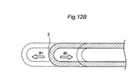
- the two sides 3 and 3 which are the long sides of the air bag 1 are formed by bending a single resin sheet. Therefore, when an external force in the direction of arrow A is applied to the air bag 1, the air bag 1 easily rolls in the direction in which the external force acts, causing a lateral shift. That is, the long side 3 of the air bag 1 extends in the direction a1 that receives the external force or is contracted in the direction a2 as shown in the PP cross section of FIG. The position of changes.
- an object of the present invention is to provide a cuff for a blood pressure information measuring device and a blood pressure information measuring device capable of applying a sufficient compression force to a measurement site with a simple configuration.
- the present invention has the following configuration.
- a blood pressure information measurement cuff that has a belt-like cuff body and a fluid bag that is attached to the cuff body and expands and contracts when fluid enters and exits, and is used by being wound around a subject.
- the fluid bag is formed into a rectangular bag shape in which the cylindrical resin sheet is flattened and the both open ends are sealed, Partial welding in which the resin sheet is folded and welded to a part of at least one of the opposing sides of the pair of opposing sides that intersects the sides of the sealed both ends and extends along the winding direction of the subject.
- Blood pressure information measurement cuff formed with a part.
- a blood pressure information acquisition unit for acquiring blood pressure information;
- a blood pressure information measuring device A blood pressure information measuring device.
- a sufficient compression force can be applied to the measurement site with a simple configuration, and high-precision blood pressure measurement can be realized.
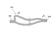
- FIG. 7 is a schematic cross-sectional view between QQ of the air bag shown in FIG. 6.
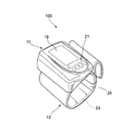
- FIG. 1 is a diagram for explaining an embodiment of the present invention, and is an overall configuration diagram showing a configuration of a blood pressure information measuring device.
- the blood pressure information measurement device (hereinafter, abbreviated as a sphygmomanometer) 100 mainly includes a device body 11 as a blood pressure information acquisition unit and a sphygmomanometer cuff (hereinafter abbreviated as a cuff) 13.
- the illustrated sphygmomanometer 100 is a wrist blood pressure information measuring device that measures blood pressure information such as a blood pressure value in a state where the cuff 13 is worn on the wrist of a subject.
- the blood pressure information includes a blood pressure value, a pulse wave waveform, a heart rate, and the like, a maximum blood pressure value, a minimum blood pressure value, a pulse rate, a pulse wave amplitude, an AI (Augmentation Index) value calculated from them, TR (Time of Reflection) value and the like are included.
- the apparatus main body 11 and the cuff 13 are integrally formed, and the apparatus main body 11 and the cuff 13 are connected from an air connection port provided on the cuff 13 side to the apparatus main body via an air channel (not shown). .
- the apparatus main body 11 is provided with a display unit 19 for displaying information and an input operation unit 21 for inputting various information.
- the display unit 19 displays the blood pressure value, the measurement result of the pulse rate, and the like visually using numerical values, graphs, and the like.
- a liquid crystal panel or the like is used as the display unit 19.
- the input operation unit 21 is provided with a power button, a measurement start button, and various buttons for inputting information on the subject.
- the cuff 13 is formed in a band shape as a whole, and is used by being wrapped around the wrist of the subject.
- the cuff 13 has an air bag 23 which is a fluid bag for pressing the wrist, and a bag-like cover body 25 as a cuff body for wrapping the air bag 23 around the wrist of the subject.
- FIG. 2 is a functional block diagram of the blood pressure information measuring device shown in FIG.
- the apparatus main body 11 is provided with an air system component 27 for blood pressure measurement for supplying or discharging air to / from an air bag 23 contained in the cuff 13.
- the blood pressure measurement air system component 27 includes a pressure sensor 29 that detects the pressure in the air bladder 23, and a pump 33 and a valve 35 that are expansion and contraction mechanisms 31 that inflate and contract the air bladder 23.
- An oscillation circuit 37, a pump drive circuit 39, and a valve drive circuit 41 are provided in the apparatus main body 11 in association with the blood pressure measurement air system component 27.
- the apparatus main body 11 stores a CPU (Central Processing Unit) 43 as a control unit that controls and monitors each unit intensively, various programs such as a program for causing the CPU 43 to perform a predetermined operation, and a measured blood pressure value.
- the memory unit 45, the display unit 19 and the input operation unit 21 described above, and a power source unit 47 that supplies power as a power source to the CPU 43 are provided.
- the CPU 43 also functions as blood pressure value calculation means for calculating blood pressure values.
- the pressure sensor 29 detects the pressure in the air bag 23 (hereinafter referred to as “cuff pressure”), and outputs a signal corresponding to the detected cuff pressure to the oscillation circuit 37.
- the pump 33 supplies air to the air bag 23.
- the valve 35 opens and closes when maintaining the pressure in the air bladder 23 or exhausting the air in the air bladder 23.
- the oscillation circuit 37 outputs a signal having an oscillation frequency corresponding to the output value of the pressure sensor 29 to the CPU 43.
- the pump drive circuit 39 controls the drive of the pump 33 based on a control signal given from the CPU 43.
- the valve drive circuit 41 performs opening / closing control of the valve 35 based on a control signal given from the CPU 43.
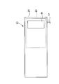
- FIG. 3 is a plan view of the cuff 13.
- the cuff 13 has an air bag 23 and a bag-like cover body 25.
- the bag-like cover body 25 is formed in a bag shape by superimposing two sheet-like members composed of an inner cover and an outer cover and joining the peripheral edges thereof.
- a surface fastener 51 made of, for example, Velcro (registered trademark) is provided on the outside of the cuff 13 and the air bag 23, a surface fastener 51 made of, for example, Velcro (registered trademark) is provided.
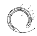
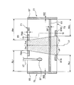
- FIG. 4 is a cross-sectional view showing a state where the cuff 13 is wound around the wrist of the subject.
- a curler 53 may be interposed between the air bag 23 and the bag-like cover body 25.
- the curler 53 is made of a flexible member configured to be elastically deformable in the radial direction by being wound in an annular shape.
- the curler 53 is bonded and fixed to the outer peripheral surface of the air bag 23 via an adhesive member such as a double-sided tape (not shown), and is configured to follow the wrist by maintaining its own annular shape.
- the curler 53 is intended to make it easier for the subject to attach the cuff 13 to the wrist, and to urge the air bag 23 toward the inside of the wrist when the cuff 13 is attached to the wrist.
- the curler 53 is formed of a resin member such as polypropylene (PP) so as to exhibit a sufficient elastic force.
- PP polypropylene
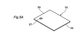
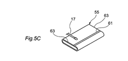
- FIG. 5A, FIG. 5B, FIG. 5C, and FIG. 5D are explanatory views showing a method for manufacturing the air bladder 23.
- FIG. 5A As a manufacturing procedure of the air bag 23, first, as shown in FIG. 5A, one rectangular resin sheet 55 is prepared.
- the resin sheet 55 is a flexible sheet made of, for example, ethylene-vinyl acetate copolymer (EVA), soft vinyl chloride (PVC), polyurethane (PU), natural rubber (NR), or the like.
- EVA ethylene-vinyl acetate copolymer
- PVC soft vinyl chloride
- PU polyurethane
- NR natural rubber
- the other inner surface is formed on one outer surface of the opposite end portions 59, 59 of the resin sheet 55. They are superposed on the inside and outside so as to come into contact with each other, and the overlapping portions are welded by a high frequency welder or the like. Thereby, the resin sheet 55 becomes a cylindrical body, and the 1st welding part 61 along the axial direction of a cylindrical body is formed.
- the cylindrical body processed in FIG. 5B is flattened.
- the flattened resin sheet 55 has both ends 63, 63 of the cylindrical body open.
- the open ends 63 and 63 are welded by a high frequency welder or the like to form second welded portions 65 and 67.
- the air bag 23 manufactured as described above has a rectangular shape in plan view, and the cuff 13 has a long side portion in the circumferential direction when wound around the wrist and a short side portion in the longitudinal direction perpendicular to the circumferential direction. Housed inside.
- the length of the long side part is, for example, 100 mm or more and 220 mm or less, and the length of the short side part can be, for example, 40 mm or more and less than the length of the long side part.
- the air bag 23 can be formed in a square shape or other polygonal shapes.
- FIG. 6 is a plan view of the air bag in the first configuration example.
- the air bag 23A of this configuration example has a pair of opposing sides along the winding direction of the subject, long sides 71 and 73, and a pair of short sides 75 and 77 along the direction orthogonal to the winding direction, as viewed in plan view. It is formed in a rectangular shape.
- the air bag 23A is formed with the aforementioned first welded portion 61 and second welded portions 65, 67.
- the air bag 23A has partial welded portions 79A and 79B in which the resin sheet 55 is folded up and down on a part of the long sides 71 and 73 and welded. , 81A, 81B are formed.
- the partial welds 79A and 79B are formed on the long side 71 side, and the partial welds 81A and 81b are formed on the long side 73 side.
- the air bag 23A is formed in a rectangular bag shape in which a cylindrical resin sheet is flattened and both open ends are sealed. At least part of the long sides 71 and 73 (both in the present configuration example) of the pair of opposing sides that cross the sides of the sealed both ends and extend along the winding direction of the subject. Partially welded portions 79A, 79B, 81A, 81B are formed by folding and welding the resin sheets.
- the partial welds 79A, 79B, 81A, 81B are discretely formed on both sides of the long sides 71, 73 with respect to the central region 83 in the winding direction of the air bag 23A.
- the air bag 23A is formed in a rectangular shape having a pair of opposing sides as long sides and a pair of opposing sides along a direction orthogonal to the winding direction as short sides.
- the partial welded portion 79A is formed in the first end region AL1 which is one side of the central region 83 on the long side 71, and the partial welded portion 79B is formed in the second end region AR1 which is the other side. It is formed.
- the partial welded portion 81A is formed in the first end region AL2 that is one side of the central region 83 on the long side 71, and the partial welded portion 81B is the second end region that is the other side. Formed in AR2.
- the partial weld portion 79A is formed at the boundary position between the central region 83 and the first end region AL1
- the partial weld portion 79B is formed at the boundary position between the central region 83 and the second end region AR1.
- the partial weld 81A is formed at the boundary position between the central region 83 and the first end region AL2
- the partial weld 81B is formed at the boundary position between the central region 83 and the second end region AR2.
- each partial weld part 79A, 79B, 81A, 81B is formed alternately along the winding direction (direction along the long side).
- the partial welded portions 79A, 79B, 81A, 81B are formed at positions that are biased near both ends except for the central region 83 of the long sides 71, 73 so that the measurement site can be compressed with sufficient force. Is done.
- a partial welded portion is formed in the central region 83.
- the expansion of the central portion of the air bag 23A is not hindered.
- the partial welded portions 79A, 79B, 81A, 81B are provided in the vicinity of the central region 83 that avoids the central region 83, it is possible to sufficiently secure the compression area for the portion of the subject that is most desired to be compressed.
- the partial welds 79A and 79B in this configuration example are formed with a distance La from the center line Lc, and the partial welds 81A and 81B are formed with a distance Lb longer than the distance La from the stop line or Lc.
- the central region 83 is defined in a trapezoidal shape, and a long side 73 serving as the longer base is disposed on the proximal side (side closer to the trunk) of the subject. Further, the shorter long side 71 is arranged on the distal side of the subject (the side far from the trunk).
- the partial welded portions 79A, 79B, 81A, 81B prevent the lateral displacement along the short sides 75, 77 of the air bag 23A.
- the partial welded portion 79B prevents the extension in the direction a1 shown in FIG. 12B.
- the partially welded portion 81B prevents degeneration in the direction a2 shown in FIG. 12B.
- the welding margin width W3 in the direction orthogonal to the outer edge sides (long sides 71 and 73) of the air bag 23A is the welding margin width W1 from the edge portion of the first welding portion 61, the second welding portion 65, It is preferable that the welding allowance width W2 from the edge portion 67 is narrower. By narrowing the welding allowance width W3, the influence on the inflation of the air bag 23A can be minimized.
- the shape of the partially welded portions 79A, 79B, 81A, 81B is not limited to the rectangular shape in the illustrated example, but may be other shapes.
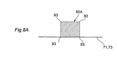
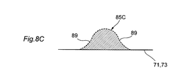
- 8A, 8B, 8C, and 8D are plan views showing variations in the shape of the partially welded portion.
- 8A is a partial welded portion 85A having a square shape
- FIG. 8B is a partially welded portion 85B having a shape including a semicircular portion
- FIG. 8C is a partially welded portion 85C having a shape having an expanded base
- FIG. 8D is a partial weld having a trapezoidal shape. This is the case of the part 85D.
- the partial welded portion can obtain the above effect regardless of the shape. Further, when the semicircular portion 87 shown in FIG. 8B, the skirt portion 89 shown in FIG. 8C, and the trapezoid hypotenuse 91 shown in FIG. 8D are formed, the air bag 23A in the corner portion 93 shown in FIG. The stress concentration can be alleviated and the durability of the air bag 23A can be further improved.
- the partially welded portions having various shapes are alternately formed along the winding direction on the long sides 71 and 73 which are a pair of opposite sides of the air bag 23A. That is, the center position of each partial welded portion is disposed at a different position with respect to the directions of the short sides 75 and 77 when the air bag 23A is viewed in plan. Thereby, it is possible to prevent wrinkles from occurring in the air bag 23A when the air bag 23A is inflated.
- the arrangement position and size of the partially welded portion can be exemplified as follows for the partially welded portion shown in FIG. 6, for example. Assuming that the central region 83 of the air bag 23A corresponding to the region to be most compressed of the subject is within a range of 60 mm near the center line Lc of the air bag 23A, the partially welded portions 79A, 79B. 81A and 81B can be about 3 mm in the circumferential direction (long side direction) when wound around the subject and about 1 mm in the short side direction orthogonal to the circumferential direction. Further, these rectangular partial welds 79A, 79B, 81A, 81B can be alternately formed along the long sides 71, 73, for example, at an interval of 8 mm at the center of the weld.
- FIG. 9 shows a modification of the arrangement of the partial welds.
- the partial welded portion may be arranged in the vicinity of the central region 83 of the air bag 23A. That is, the partial welds 95A and 95B shown in FIG. 9 are formed outside the central region 83, but the partial welds 97A and 97B are disposed in the central region 83 in the vicinity of the central region 83. Also good.
- the partial welded portions 95A, 95B, 97A, and 97B are formed by dividing the trapezoidal partial welded portion shown in FIG. 8D into two parts, and the trapezoidal oblique sides coincide with the boundary line of the central region 83.
- the long side width W4 of the welding allowance can be narrowed by arranging the partial welded portions 95A, 95B, 97A, 97B in consideration of the taper of the trapezoid oblique sides.
- FIG. 10 is a plan view of an air bag in the second configuration example.
- the air bag 23 ⁇ / b> B of this configuration example forms partial welded portions 99 ⁇ / b> A, 99 ⁇ / b> B, 101 ⁇ / b> A, 101 ⁇ / b> B continuous along the long sides 71, 73 on the long sides 71, 73 excluding the central region 83.
- One end of the partial weld 99A is connected to the second weld 65 on the long side 71 of the air bag 23B, and the other end extends continuously to the boundary with the central region 83.
- the partial weld 99B is connected to the second weld 67 and extends continuously to the boundary with the central region 83.
- the partial welds 101 ⁇ / b> A and 101 ⁇ / b> B are connected to the second welds 65 and 67 and extend continuously to the boundary with the central region 83.
- the welding allowance width W5 from the edge portions (71, 73) of these partial weld portions 99A, 99B, 101A, 101B is the welding allowance width W1, from the edge portion of the first weld portion 61, the second weld portion 65, It is formed narrower than the welding allowance width W2 from the edge of 67.
- the welding allowance width W5 is set to be 70% to 90% of the welding allowance widths W1 and W2.
- the continuous partial welded portions 99A, 99B, 101A, 101B can more reliably prevent the occurrence of lateral displacement, and a sufficient compression force can be applied to the measurement site.
- FIG. 11 is a plan view showing a cuff in the third configuration example.
- the cuff 13A has a shape in which one long side 105 of the belt-like shape is curved longer than the other long side 107 in consideration of the state of being wound around the subject.
- the long side 105 is disposed on the proximal side (the side closer to the trunk) of the subject, and the shorter long side 107 is disposed on the distal side (the side far from the trunk).
- the air bag 23C accommodated in the cuff 13A in this case forms the partial welded portions 103A and 103B only on the long side 73 disposed on the long side 105 side of the cuff 13A, and the partial weld on the opposite long side 107. Does not form part.
- the air bag 23 ⁇ / b> C may have a configuration in which a partial weld portion having a welding allowance narrower than the long side 105 is formed on the long side 107.
- a partial weld portion having a welding allowance narrower than the long side 105 is formed on the long side 107.
- the welding margin width of the partial welded portion of the long side 107 is 0.8 mm, and the portion on the long side 105 side
- the welding area of the welded portion can be made relatively larger than the partial welded portion on the long side 107 side.
- the present invention is not limited to the above-described embodiments, and the configurations of the embodiments may be combined with each other, or may be modified or applied by those skilled in the art based on the description of the specification and well-known techniques.
- the invention is intended and is within the scope of seeking protection.
- the above blood pressure information measurement device has been described by taking a wrist type as an example, the present invention is not limited to the wrist type, and may have a device configuration applicable to any of the four limbs.
- a blood pressure information measurement cuff that has a belt-like cuff body and a fluid bag that is attached to the cuff body and expands and contracts when fluid enters and exits, and is used by being wound around a subject.
- the fluid bag is formed into a rectangular bag shape in which the cylindrical resin sheet is flattened and the both open ends are sealed, Partial welding in which the resin sheet is folded and welded to a part of at least one of the opposing sides of the pair of opposing sides that intersects the sides of the sealed both ends and extends along the winding direction of the subject.
- Blood pressure information measurement cuff formed with a part.
- the blood pressure information measurement cuff of (1) The partial welded portion is a blood pressure information measurement cuff formed on both sides of the opposite side with respect to a central region in the winding direction of the fluid bag.
- the blood pressure information measurement cuff according to (2) The fluid bag is formed in a rectangular shape having the pair of opposed sides as long sides and the pair of opposed sides along a direction orthogonal to the winding direction as short sides,
- the partial welded portions are cuffs for measuring blood pressure information that are respectively formed in a first end region on one side of the central region on the long side and a second end region on the other side. .
- the blood pressure information measurement cuff of (3), The partial welded portion is a blood pressure information measurement cuff formed discretely in each of the first end region and the second end region.
- the blood pressure information measurement cuff according to (4), The partial weld portion is a blood pressure information measurement cuff formed at a boundary position between the central region and the first end region and a boundary position between the central region and the second end region.
- the blood pressure information measurement cuff according to (3), The partial welded portion is a blood pressure information measurement cuff that extends over the entire first end region and the second end region.
- the blood pressure information measurement cuff according to any one of (1) to (6),
- the fluid bag is formed by flattening the cylindrical body with respect to the cylindrical body having the first welded portion where the edges of the pair of opposite sides of the rectangular resin sheet are overlapped, and the remaining bag opening.
- a cuff for measuring blood pressure information which has a second welded portion in which two edge portions are welded, and is formed in a bag shape.
- the blood pressure information measurement cuff according to (7), The partial weld portion is for measuring blood pressure information in which a welding margin width in a direction orthogonal to a side of an outer edge of the welded fluid bag is narrower than the welding margin width with respect to the first welding portion and the second welding portion. Cuff.
- the blood pressure information measurement cuff according to any one of (1) to (8), The partial weld portion is a blood pressure information measurement cuff formed on both of the pair of opposing sides.
- the blood pressure information measurement cuff according to (9), The partial welded portions are blood pressure information measurement cuffs that are alternately formed on the pair of opposing sides along the winding direction.
- the blood pressure information measurement cuff according to any one of (1) to (10), The cuff body has a curved shape in which one of the pair of long sides in a band shape is longer than the other, The partial welded portion is for blood pressure information measurement formed only on the opposite side disposed on the longer long side of the cuff body among the pair of opposite sides of the fluid bag accommodated in the cuff body.
- the blood pressure information measurement cuff according to any one of (1) to (10),
- the cuff body has a curved shape in which one of the pair of long sides in a band shape is longer than the other, Of the pair of opposing sides of the fluid bag accommodated in the cuff body, the partial welded portion has a welding area of the opposing side disposed on the longer long side of the cuff body on the other side. Blood pressure information measurement cuff larger than the welding area of the opposite side to be arranged.
- the cuff for a blood pressure information measuring device and the blood pressure information measuring device of the present invention are useful when used for a wrist type blood pressure information measuring device that measures blood pressure information such as blood pressure values while being worn on the wrist of a subject, for example.
- a wrist type blood pressure information measuring device that measures blood pressure information such as blood pressure values while being worn on the wrist of a subject, for example.
Landscapes
- Health & Medical Sciences (AREA)
- Life Sciences & Earth Sciences (AREA)
- Vascular Medicine (AREA)
- Cardiology (AREA)
- Engineering & Computer Science (AREA)
- Surgery (AREA)
- Public Health (AREA)
- Veterinary Medicine (AREA)
- Biophysics (AREA)
- Pathology (AREA)
- Physics & Mathematics (AREA)
- Biomedical Technology (AREA)
- Heart & Thoracic Surgery (AREA)
- Medical Informatics (AREA)
- Molecular Biology (AREA)
- General Health & Medical Sciences (AREA)
- Animal Behavior & Ethology (AREA)
- Dentistry (AREA)
- Ophthalmology & Optometry (AREA)
- Physiology (AREA)
- Mechanical Engineering (AREA)
- Measuring Pulse, Heart Rate, Blood Pressure Or Blood Flow (AREA)
Description
本発明は、血圧情報測定装置用カフ及び血圧情報測定装置に関する。
血圧情報測定装置は、被験者の脈波や血圧値等の血圧情報を取得するものである。血圧情報測定装置により血圧情報を測定する際は、まず、生体内部の動脈を圧迫する流体袋が内包されるカフを生体の体表面に巻き付ける。次いで、巻き付けたカフ内の流体袋を加圧・減圧し、動脈内に生じる動脈圧の脈波を検出する。そして、この検出された脈波に基づいて各種血圧値の検出を行う。
ここで、カフとは、内腔を有する帯状構造物であって、生体の一部に巻き付けが可能なものを意味し、気体や液体等の流体を内腔に注入することによって上下肢の動脈圧測定等に利用されるものを指す。したがって、カフは、流体袋とこの流体袋を生体に巻き付けるための巻付手段とを含めた概念を示すものである。
ここで、カフとは、内腔を有する帯状構造物であって、生体の一部に巻き付けが可能なものを意味し、気体や液体等の流体を内腔に注入することによって上下肢の動脈圧測定等に利用されるものを指す。したがって、カフは、流体袋とこの流体袋を生体に巻き付けるための巻付手段とを含めた概念を示すものである。
血圧情報測定装置用のカフには、流体袋としての空気袋を内包する袋状カバー体が設けられる。この袋状カバー体は、通常、内側カバー及び外側カバーからなる2枚のシート状部材を重ね合わせ、その周縁を結合することによって袋状に形成される。このような空気袋を内包するカフの構造は、例えば特許文献1,2等に開示されている。
特許文献1や特許文献2に開示される血圧情報測定装置用カフにおいては、内包される空気袋を次のように製造している。即ち、一枚の方形の樹脂シートにおける両端の対向する二辺部(長辺)を重ね合わせて溶着して筒状とし、その筒状体となった樹脂シートを扁平にして両端の開口した二辺部(短辺)をそれぞれ溶着する。これにより、周端の閉塞された構造の空気袋が得られる。
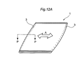
上記構造のカフは、図12Aに示すように、空気袋1が細長状に形成される。空気袋1の長辺となる二辺3,3は、一枚の樹脂シートが折り曲げられて形成されている。そのため、空気袋1に矢印A方向の外力が加わると、空気袋1は外力の作用する方向へ容易に転がり、横ずれが生じるようになる。つまり、図12Bに図12AのP-P断面を示すように、空気袋1の長辺3が、外力を受けた方向a1に延出されたり、方向a2に縮退されたりして、矢印A方向の位置が変化する。
空気袋1に横ずれが生じると、体表面の被測定部位への圧迫点がずれてしまい、圧迫力の損失が生じて充分な圧迫力を被測定部位に作用させにくくなる。その結果、正確な血圧情報が得にくくなる虞が生じ得る。
そこで、本発明は、簡便な構成で十分な圧迫力を被測定部位に作用させることができる血圧情報測定装置用カフ及び血圧情報測定装置を提供することを目的とする。
空気袋1に横ずれが生じると、体表面の被測定部位への圧迫点がずれてしまい、圧迫力の損失が生じて充分な圧迫力を被測定部位に作用させにくくなる。その結果、正確な血圧情報が得にくくなる虞が生じ得る。
そこで、本発明は、簡便な構成で十分な圧迫力を被測定部位に作用させることができる血圧情報測定装置用カフ及び血圧情報測定装置を提供することを目的とする。
本発明は下記構成からなる。
(1) 帯状のカフ本体、及び前記カフ本体に取り付けられ流体が入出することにより膨縮する流体袋を有し、被検体に巻き付けて使用される血圧情報測定用カフであって、
前記流体袋は、筒状の樹脂シートを扁平とし、開口する両端部を密閉した方形の袋状に形成され、
前記密閉された両端部の辺に交差し、前記被検体への巻き付け方向に沿う一対の対向辺のうち、少なくとも一方の前記対向辺の一部に、前記樹脂シートを折り重ねて溶着した部分溶着部が形成された血圧情報測定用カフ。
(2)上記血圧情報測定用カフと、
前記流体袋を膨縮させる膨縮機構と、
血圧情報を取得する血圧情報取得部と、
を備えた血圧情報測定装置。
(1) 帯状のカフ本体、及び前記カフ本体に取り付けられ流体が入出することにより膨縮する流体袋を有し、被検体に巻き付けて使用される血圧情報測定用カフであって、
前記流体袋は、筒状の樹脂シートを扁平とし、開口する両端部を密閉した方形の袋状に形成され、
前記密閉された両端部の辺に交差し、前記被検体への巻き付け方向に沿う一対の対向辺のうち、少なくとも一方の前記対向辺の一部に、前記樹脂シートを折り重ねて溶着した部分溶着部が形成された血圧情報測定用カフ。
(2)上記血圧情報測定用カフと、
前記流体袋を膨縮させる膨縮機構と、
血圧情報を取得する血圧情報取得部と、
を備えた血圧情報測定装置。
本発明によれば、簡便な構成で十分な圧迫力を被測定部位に作用させることができ、高精度な血圧測定を実現できる。
以下、本発明の実施形態について、図面を参照して詳細に説明する。
図1は本発明の実施形態を説明するための図で、血圧情報測定装置の構成を示す全体構成図である。
血圧情報測定装置(以下、血圧計と略称する)100は、主に、血圧情報取得部としての装置本体11と、血圧計用カフ(以下、カフと略称する)13とを備える。例示した血圧計100は、カフ13を被験者の手首に装着した状態で血圧値等の血圧情報の測定を行う手首式血圧情報測定装置である。
図1は本発明の実施形態を説明するための図で、血圧情報測定装置の構成を示す全体構成図である。
血圧情報測定装置(以下、血圧計と略称する)100は、主に、血圧情報取得部としての装置本体11と、血圧計用カフ(以下、カフと略称する)13とを備える。例示した血圧計100は、カフ13を被験者の手首に装着した状態で血圧値等の血圧情報の測定を行う手首式血圧情報測定装置である。
血圧情報には、血圧値、脈波波形、心拍数等と、それらより算出される、最高血圧値、最低血圧値、脈拍数、脈波振幅、AI(Augmentation Index:脈波増大係数)値、TR(Time of Reflection:出現時間差)値等とが含まれる。
装置本体11とカフ13とは一体に構成されており、装置本体11とカフ13とは、カフ13側に設けられたエア接続口から装置本体まで図示しないエア流路を介して接続されている。
装置本体11は、情報表示用の表示部19及び各種情報を入力する入力操作部21が設けられる。表示部19は、血圧値や脈拍数の測定結果等を、数値やグラフなどを用いて視覚可能に表示する。この表示部19としては、例えば液晶パネル等が使用される。入力操作部21には、電源ボタン、測定開始ボタン、被検者に関する情報を入力するための各種ボタンが設けられている。
カフ13は、全体が帯形状に形成されており、被験者の手首に巻き付けて使用される。カフ13は、手首を圧迫するための流体袋である空気袋23と、空気袋23を被検者の手首に巻き付けて装着するためのカフ本体としての袋状カバー体25を有する。
図2は図1に示す血圧情報測定装置の機能ブロック図である。
装置本体11には、カフ13内に内包された空気袋23に空気を供給又は排出するための血圧測定用エア系コンポーネント27が設けられている。血圧測定用エア系コンポーネント27は、空気袋23内の圧力を検出する圧力センサ29と、空気袋23を膨縮させる膨縮機構31であるポンプ33及び弁35を有する。装置本体11の内部には、血圧測定用エア系コンポーネント27に関連して、発振回路37、ポンプ駆動回路39及び弁駆動回路41が設けられている。
装置本体11には、カフ13内に内包された空気袋23に空気を供給又は排出するための血圧測定用エア系コンポーネント27が設けられている。血圧測定用エア系コンポーネント27は、空気袋23内の圧力を検出する圧力センサ29と、空気袋23を膨縮させる膨縮機構31であるポンプ33及び弁35を有する。装置本体11の内部には、血圧測定用エア系コンポーネント27に関連して、発振回路37、ポンプ駆動回路39及び弁駆動回路41が設けられている。
装置本体11には、各部を集中的に制御及び監視する制御部としてのCPU(Central Processing Unit)43と、CPU43に所定の動作をさせるプログラムや測定された血圧値などの各種情報を記憶するためのメモリ部45と、前述の表示部19及び入力操作部21と、CPU43に電源としての電力を供給する電源部47とが設けられている。CPU43は、血圧値を算出するための血圧値算出手段としても機能する。
圧力センサ29は、空気袋23内の圧力(以下、「カフ圧」という)を検出し、検出したカフ圧に応じた信号を発振回路37に出力する。ポンプ33は、空気袋23に空気を供給する。弁35は、空気袋23内の圧力を維持したり、空気袋23内の空気を排出したりする際に開閉動作する。発振回路37は、圧力センサ29の出力値に応じた発振周波数の信号をCPU43に出力する。ポンプ駆動回路39は、ポンプ33の駆動をCPU43から与えられる制御信号に基づいて制御する。弁駆動回路41は、CPU43から与えられる制御信号に基づいて弁35の開閉制御を行う。
図3はカフ13の平面図である。カフ13は、空気袋23と袋状カバー体25とを有する。袋状カバー体25は、内側カバー及び外側カバーからなる2枚のシート状部材を重ね合わせ、その周縁を結合することによって袋状に形成される。カフ13及び空気袋23の外側には、例えばマジックテープ(登録商標)からなる面ファスナ51が設けられている。
図4はカフ13を被検者の手首に巻き掛けた状態としての断面図である。カフ13は、空気袋23と袋状カバー体25との間にカーラ53が介装されていてもよい。カーラ53は、環状に巻き回されることによって径方向に弾性変形可能に構成された可撓性の部材からなる。カーラ53は、空気袋23の外周面に図示しない両面テープ等の接着部材を介して接着・固定されており、自身の環状形態を維持することによって手首に沿うように構成される。このカーラ53は、被験者自身によってカフ13を手首に装着し易くするためのものであるとともに、カフ13の手首への装着状態において空気袋23を手首内側に向けて付勢するためのものである。なお、カーラ53は、十分な弾性力を発現するように、例えばポリプロピレン(PP)等の樹脂部材にて形成される。
次に、上記の空気袋23の製造方法について説明する。
図5A,図5B,図5C,図5Dは空気袋23の製造方法を示す説明図である。空気袋23の製造手順としては、まず、図5Aに示すように、1枚の方形状の樹脂シート55を用意する。樹脂シート55は、例えばエチレン-酢酸ビニル共重合体(EVA)、軟質塩化ビニル(PVC)、ポリウレタン(PU)、天然ゴム(NR)等からなる柔軟なシートである。樹脂シート55の一部には、接続管17を取り付けるための孔57を穿設する。
図5A,図5B,図5C,図5Dは空気袋23の製造方法を示す説明図である。空気袋23の製造手順としては、まず、図5Aに示すように、1枚の方形状の樹脂シート55を用意する。樹脂シート55は、例えばエチレン-酢酸ビニル共重合体(EVA)、軟質塩化ビニル(PVC)、ポリウレタン(PU)、天然ゴム(NR)等からなる柔軟なシートである。樹脂シート55の一部には、接続管17を取り付けるための孔57を穿設する。
次に、樹脂シート55に設けた孔57に接続管17を取り付けた後、図5Bに示すように、樹脂シート55における対向する二辺の両端部59,59の一方の外面に他方の内面が接触するように内外に重ね合わせ、その重合する箇所を高周波ウェルダ等により溶着する。これにより、樹脂シート55は筒状体となり、筒状体の軸方向に沿った第1の溶着部61が形成される。
次いで、図5Cに示すように、図5Bで加工された筒状体を扁平状に潰す。扁平にされた樹脂シート55は、筒状体の両端63,63が開口している。図5Dに示すように、その開口した両端63,63を高周波ウェルダ等により溶着して、第2の溶着部65,67を形成する。上記のように製造される空気袋23は、平面視で長方形状であり、長辺部が手首に巻いた際の周方向、短辺部が周方向に直交する長手方向となるようにカフ13内に収容される。長辺部の長さは、例えば100mm以上、220mm以下であり、短辺部の長さは、例えば40mm以上で長辺部の長さ未満の長さとすることができる。なお、空気袋23は正方形状や他の多角形状等にすることもできる。
次に、上記手順により製造される空気袋23に対し、更なる加工を行って横ずれを生じにくくした空気袋を詳細に説明する。以降の説明では、同一の部材や部位に対して同じ符号を付与することで、その説明を省略又は簡略化する。
<第1の構成例>
図6は第1の構成例における空気袋の平面図である。本構成例の空気袋23Aは、被検体への巻き付け方向に沿う一対の対向辺である長辺71,73、巻き付け方向に直交する方向に沿う一対の短辺75,77を有し、平面視で長方形状に形成されている。空気袋23Aには、前述の第1の溶着部61,第2の溶着部65,67が形成されている。
<第1の構成例>
図6は第1の構成例における空気袋の平面図である。本構成例の空気袋23Aは、被検体への巻き付け方向に沿う一対の対向辺である長辺71,73、巻き付け方向に直交する方向に沿う一対の短辺75,77を有し、平面視で長方形状に形成されている。空気袋23Aには、前述の第1の溶着部61,第2の溶着部65,67が形成されている。
空気袋23Aは、第1の溶着部61、第2の溶着部65,67に加えて、長辺71,73上の一部分に樹脂シート55を上下に折り重ねて溶着した部分溶着部79A,79B,81A,81Bが形成されている。部分溶着部79A,79Bは長辺71側に形成され、部分溶着部81A,81bは長辺73側に形成される。
即ち、空気袋23Aは、筒状の樹脂シートを扁平とし、開口する両端部を密閉した方形の袋状に形成されている。この密閉された両端部の辺に交差して被検体への巻き付け方向に沿う一対の対向辺である長辺71,73のうち、少なくとも一方(本構成例では双方)の長辺の一部に、樹脂シートを折り重ねて溶着した部分溶着部79A,79B,81A,81Bが形成されている。
部分溶着部79A,79B,81A,81Bは、空気袋23Aの巻き付け方向の中央領域83に対する、長辺71,73の両脇側に離散して形成される。
より詳細には、空気袋23Aは、一対の対向辺を長辺、巻き付け方向に直交する方向に沿う一対の対向辺を短辺とする長方形状に形成される。部分溶着部79Aは、長辺71上における中央領域83の一方の脇側となる第1端部領域AL1に形成され、部分溶着部79Bは、他方の脇側となる第2端部領域AR1に形成される。また、部分溶着部81Aは、長辺71上における中央領域83の一方の脇側となる第1端部領域AL2に形成され、部分溶着部81Bは、他方の脇側となる第2端部領域AR2に形成される。
本構成例においては、部分溶着部79Aは、中央領域83と第1端部領域AL1との境界位置、部分溶着部79Bは、中央領域83と第2端部領域AR1との境界位置に形成される。部分溶着部81Aは、中央領域83と第1端部領域AL2との境界位置、部分溶着部81Bは、中央領域83と第2端部領域AR2との境界位置に形成される。
また、各部分溶着部79A,79B,81A,81Bは、巻き付け方向(長辺に沿う方向)に沿って互い違いに形成されている。上記のように、各部分溶着部79A,79B,81A,81Bは、被測定部位を十分な力で圧迫できるように長辺71,73の中央領域83を除く両端部近傍に偏った位置に形成される。
空気袋23Aの長辺中央を示す中心線Lcから両短辺75,77に向けて等距離に画成される中央領域83に対しては、この中央領域83内への部分溶着部の形成を避けることで、空気袋23Aの中央部分の膨張を妨げることがない。本構成例では、部分溶着部79A,79B,81A,81Bを、中央領域83を避けた中央領域83の近傍に設けているので、被検体の最も圧迫したい部分に対する圧迫面積を十分に確保できる。
本構成例の部分溶着部79A、79Bは、中心線Lcから距離Laを空けて形成され、部分溶着部81A,81Bは、中止線かLcから距離Laより長い距離Lbを空けて形成されている。中央領域83は台形状に画成されており、長い方の底辺となる長辺73が被検体の近位側(体幹に近い側)に配置される。また、短い方の長辺71が被検体の遠位側(体幹に遠い側)に配置される。
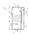
そのため、空気袋23Aに空気を注入して膨らまして被測定部位を圧迫した際、部分溶着部79A,79B,81A,81Bが、空気袋23Aの短辺75,77に沿った横ずれを防止する。図7に空気袋23Aの模式的なQ-Q間の断面図を示すように、空気袋23Aに外力Aが加わっても、部分溶着部79Bが図12Bに示す方向a1の延出を阻止し、部分溶着部81Bが図12Bに示す方向a2の縮退を阻止する。
よって、空気袋23Aを膨らませた場合に、被測定部位からずれることなく、十分な圧迫力を安定して作用させることができる。この横ずれの防止効果は、空気袋23Aに空気を供給して空気袋23Aが膨らみ始めたときから膨張を完了するまでの期間、及び膨張した状態で保持され続ける期間の双方で得ることができる。
なお、空気袋23Aの外縁の辺(長辺71,73)に直交する方向の溶着代幅W3は、第1の溶着部61の縁部からの溶着代幅W1、第2の溶着部65,67の縁部からの溶着代幅W2より狭くすることが好ましい。溶着代幅W3を狭くすることで、空気袋23Aの膨張への影響を最小限に抑えることができる。
部分溶着部79A,79B,81A,81Bの形状は、図示例の長方形状に限らず、他の形状にすることができる。
図8A,図8B,図8C,図8Dは、部分溶着部の形状のバリエーションを示す平面図である。図8Aは正方形の部分溶着部85A、図8Bは半円部を含む形状の部分溶着部85B、図8Cは図8Bの裾野を広げた形状の部分溶着部85C、図8Dは台形状の部分溶着部85Dの場合である。
図8A,図8B,図8C,図8Dは、部分溶着部の形状のバリエーションを示す平面図である。図8Aは正方形の部分溶着部85A、図8Bは半円部を含む形状の部分溶着部85B、図8Cは図8Bの裾野を広げた形状の部分溶着部85C、図8Dは台形状の部分溶着部85Dの場合である。
部分溶着部は、いずれの形状とした場合でも上記効果を得ることができる。そして更に、図8Bに示す半円部87、図8Cに示す裾野部89、図8Dに示す台形斜辺部91を形成した場合には、図8Aに示す角部93における空気袋23Aの膨張時の応力集中を緩和でき、空気袋23Aの耐久性をより向上できる。
各種形状の部分溶着部は、被測定部位にカフ13を装着した場合に、空気袋23Aの一対の対辺である長辺71,73に、それぞれ巻き付け方向に沿って互い違いに形成される。即ち、各部分溶着部の中心位置は、空気袋23Aを平面視した場合の短辺75,77方向に対して、それぞれ異なる位置に配置される。これにより、空気袋23Aの膨張時に空気袋23Aに皺が生じることを防止できる。
部分溶着部の配置位置やサイズは、例えば、図6に示す部分溶着部については、次のように例示できる。被検体の最も圧迫したい領域に対応する空気袋23Aの中央領域83が、空気袋23Aの中心線Lc付近の60mmの範囲であるとすると、部分溶着部79A,79B.81A,81Bは、被検体に巻いた際の周方向(長辺方向)に3mm程度、周方向に直交する短辺方向に1mm程度とすることができる。また、これら長方形の部分溶着部79A,79B,81A,81Bを、長辺71,73に沿って、例えば溶着部中心位置で8mm間隔として互い違いに形成することができる。
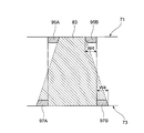
図9は部分溶着部の配置の変形例を示す。
部分溶着部は、空気袋23Aの中央領域83の近傍に配置した構成としてもよい。即ち、図9に示す部分溶着部95A,95Bは、中央領域83の外側に形成しているが、部分溶着部97A,97Bについては、中央領域83の近傍で、中央領域83内に配置してもよい。この場合の部分溶着部95A,95B,97A,97Bは、図8Dに示す台形状の部分溶着部を二分した形状として、台形斜辺部を中央領域83の境界線に一致させている。
部分溶着部は、空気袋23Aの中央領域83の近傍に配置した構成としてもよい。即ち、図9に示す部分溶着部95A,95Bは、中央領域83の外側に形成しているが、部分溶着部97A,97Bについては、中央領域83の近傍で、中央領域83内に配置してもよい。この場合の部分溶着部95A,95B,97A,97Bは、図8Dに示す台形状の部分溶着部を二分した形状として、台形斜辺部を中央領域83の境界線に一致させている。
本変形例による部分溶着部の配置によれば、部分溶着部95A,95B,97A,97Bの台形斜辺部のテーパーを考慮しつつ配置することで、溶着代の長辺幅W4を狭くできる。
<第2の構成例>
図10は、第2の構成例における空気袋の平面図である。本構成例の空気袋23Bは、中央領域83を除く長辺71,73に、長辺71,73に沿って連続した部分溶着部99A,99B,101A,101Bを形成している。部分溶着部99Aの一端は、空気袋23Bの長辺71の第2の溶着部65と接続され、他端は中央領域83との境界まで連続して延設されている。同様に、部分溶着部99Bは第2の溶着部67と接続され、中央領域83との境界まで連続して延設されている。
図10は、第2の構成例における空気袋の平面図である。本構成例の空気袋23Bは、中央領域83を除く長辺71,73に、長辺71,73に沿って連続した部分溶着部99A,99B,101A,101Bを形成している。部分溶着部99Aの一端は、空気袋23Bの長辺71の第2の溶着部65と接続され、他端は中央領域83との境界まで連続して延設されている。同様に、部分溶着部99Bは第2の溶着部67と接続され、中央領域83との境界まで連続して延設されている。
また、部分溶着部101A,101Bも同様に、第2の溶着部65,67と接続され、中央領域83との境界まで連続して延設されている。
これら部分溶着部99A,99B,101A,101Bの縁部(71,73)からの溶着代幅W5は、第1の溶着部61の縁部からの溶着代幅W1,第2の溶着部65,67の縁部からの溶着代幅W2よりも狭く形成されている。
本構成例の部分溶着部99A,99B,101A,101Bにおいては、溶着代幅W5が、溶着代幅W1,W2の70%以上90%以下の幅としている。これにより、部分溶着部を簡単な工程で形成できるため、製造工数が削減され、低コストで空気袋23Bを製造できる。
また、空気袋23Bを膨らませた際に、連続する部分溶着部99A,99B,101A,101Bによって、横ずれの発生をより確実に防止でき、充分な圧迫力を被測定部位に作用させることができる。
<第3の構成例>
図11は、第3の構成例におけるカフを示す平面図である。このカフ13Aは、被検体に巻き付けた状態を考慮して、帯状の一方の長辺105が他方の長辺107よりも長く湾曲した形状となっている。カフ13Aを被検体に巻き付けた際、長辺105が被検体の近位側(体幹に近い側)に配置され、短い方の長辺107が被検体の遠位側(体幹に遠い側)に配置される。
図11は、第3の構成例におけるカフを示す平面図である。このカフ13Aは、被検体に巻き付けた状態を考慮して、帯状の一方の長辺105が他方の長辺107よりも長く湾曲した形状となっている。カフ13Aを被検体に巻き付けた際、長辺105が被検体の近位側(体幹に近い側)に配置され、短い方の長辺107が被検体の遠位側(体幹に遠い側)に配置される。
この場合のカフ13Aに収容される空気袋23Cは、カフ13Aの長辺105側に配置される長辺73にのみ部分溶着部103A,103Bを形成し、反対側の長辺107には部分溶着部を形成しない。
上記構成によれば、部分溶着部を必要最小限の位置に配置するので、空気袋23Cの膨張が妨げられず、十分な圧迫力を被測定部位に作用させることができる。なお、空気袋23Cは、長辺107に長辺105より溶着代幅の狭い部分溶着部を形成した構成としてもよい。例えば、長辺105の部分溶着部103A,103Bの縁部からの溶着代幅が1mmであった場合、長辺107の部分溶着部の溶着代幅を0.8mmとして、長辺105側の部分溶着部の溶着面積を、長辺107側の部分溶着部より相対的に大きくすることができる。
本発明は上記の実施形態に限定されるものではなく、実施形態の各構成を相互に組み合わせることや、明細書の記載、並びに周知の技術に基づいて、当業者が変更、応用することも本発明の予定するところであり、保護を求める範囲に含まれる。上記の血圧情報測定装置は、手首式を例示して説明しているが、本発明は手首式に限らず、四肢のいずれかに対して適用可能な装置構成としてもよい。
以上の通り、本明細書には次の事項が開示されている。
(1) 帯状のカフ本体、及び前記カフ本体に取り付けられ流体が入出することにより膨縮する流体袋を有し、被検体に巻き付けて使用される血圧情報測定用カフであって、
前記流体袋は、筒状の樹脂シートを扁平とし、開口する両端部を密閉した方形の袋状に形成され、
前記密閉された両端部の辺に交差し、前記被検体への巻き付け方向に沿う一対の対向辺のうち、少なくとも一方の前記対向辺の一部に、前記樹脂シートを折り重ねて溶着した部分溶着部が形成された血圧情報測定用カフ。
(2) (1)の血圧情報測定用カフであって、
前記部分溶着部は、前記流体袋の前記巻き付け方向の中央領域に対する、前記対向辺の両脇側に形成される血圧情報測定用カフ。
(3) (2)の血圧情報測定用カフであって、
前記流体袋は、前記一対の対向辺を長辺、前記巻き付け方向に直交する方向に沿う一対の対向辺を短辺とする長方形状に形成され、
前記部分溶着部は、前記長辺上における前記中央領域の一方の脇側となる第1端部領域、及び他方の脇側となる第2端部領域に、それぞれ形成される血圧情報測定用カフ。
(4) (3)の血圧情報測定用カフであって、
前記部分溶着部は、前記第1端部領域及び前記第2端部領域の中で、それぞれ離散して形成される血圧情報測定用カフ。
(5) (4)の血圧情報測定用カフであって、
前記部分溶着部は、前記中央領域と前記第1端部領域との境界位置、及び前記中央領域と前記第2端部領域との境界位置に形成される血圧情報測定用カフ。
(6) (3)の血圧情報測定用カフであって、
前記部分溶着部は、前記第1端部領域及び前記第2端部領域の全体に延設される血圧情報測定用カフ。
(7) (1)乃至(6)のいずれか一つの血圧情報測定用カフであって、
前記流体袋は、長方形状の前記樹脂シートの一対の対辺における縁部が重なり合って溶着された第1の溶着部を有する筒状体に対し、該筒状体を扁平にして、開口する残りの二辺の縁部がそれぞれ溶着された第2の溶着部を有して袋状に形成された血圧情報測定用カフ。
(8) (7)の血圧情報測定用カフであって、
前記部分溶着部は、溶着された前記流体袋の外縁の辺に直交する方向の溶着代幅が、前記第1の溶着部及び前記第2の溶着部に対する前記溶着代幅より狭い血圧情報測定用カフ。
(9) (1)乃至(8)のいずれか一つの血圧情報測定用カフであって、
前記部分溶着部は、前記一対の対向辺の双方に形成される血圧情報測定用カフ。
(10) (9)の血圧情報測定用カフであって、
前記部分溶着部は、前記一対の対向辺に、それぞれ前記巻き付け方向に沿って互い違いに形成される血圧情報測定用カフ。
(11) (1)乃至(10)のいずれか一つの血圧情報測定用カフであって、
前記カフ本体は、帯状の一対の長辺のうち一方が他方よりも長くなる湾曲された形状を有し、
前記部分溶着部は、前記カフ本体に収容される前記流体袋の前記一対の対向辺のうち、前記カフ本体の長い方の長辺側に配置される対向辺にのみ形成される血圧情報測定用カフ。
(12) (1)乃至(10)のいずれか一つの血圧情報測定用カフであって、
前記カフ本体は、帯状の一対の長辺のうち一方が他方よりも長くなる湾曲された形状を有し、
前記部分溶着部は、前記カフ本体に収容される前記流体袋の前記一対の対向辺のうち、前記カフ本体の長い方の長辺側に配置される対向辺の溶着面積が、他方の側に配置される対向辺の溶着面積より大きい血圧情報測定用カフ。
(13) (1)乃至(12)のいずれか一つの血圧情報測定用カフと、
前記流体袋を膨縮させる膨縮機構と、
血圧情報を取得する血圧情報取得部と、
を備えた血圧情報測定装置。
(1) 帯状のカフ本体、及び前記カフ本体に取り付けられ流体が入出することにより膨縮する流体袋を有し、被検体に巻き付けて使用される血圧情報測定用カフであって、
前記流体袋は、筒状の樹脂シートを扁平とし、開口する両端部を密閉した方形の袋状に形成され、
前記密閉された両端部の辺に交差し、前記被検体への巻き付け方向に沿う一対の対向辺のうち、少なくとも一方の前記対向辺の一部に、前記樹脂シートを折り重ねて溶着した部分溶着部が形成された血圧情報測定用カフ。
(2) (1)の血圧情報測定用カフであって、
前記部分溶着部は、前記流体袋の前記巻き付け方向の中央領域に対する、前記対向辺の両脇側に形成される血圧情報測定用カフ。
(3) (2)の血圧情報測定用カフであって、
前記流体袋は、前記一対の対向辺を長辺、前記巻き付け方向に直交する方向に沿う一対の対向辺を短辺とする長方形状に形成され、
前記部分溶着部は、前記長辺上における前記中央領域の一方の脇側となる第1端部領域、及び他方の脇側となる第2端部領域に、それぞれ形成される血圧情報測定用カフ。
(4) (3)の血圧情報測定用カフであって、
前記部分溶着部は、前記第1端部領域及び前記第2端部領域の中で、それぞれ離散して形成される血圧情報測定用カフ。
(5) (4)の血圧情報測定用カフであって、
前記部分溶着部は、前記中央領域と前記第1端部領域との境界位置、及び前記中央領域と前記第2端部領域との境界位置に形成される血圧情報測定用カフ。
(6) (3)の血圧情報測定用カフであって、
前記部分溶着部は、前記第1端部領域及び前記第2端部領域の全体に延設される血圧情報測定用カフ。
(7) (1)乃至(6)のいずれか一つの血圧情報測定用カフであって、
前記流体袋は、長方形状の前記樹脂シートの一対の対辺における縁部が重なり合って溶着された第1の溶着部を有する筒状体に対し、該筒状体を扁平にして、開口する残りの二辺の縁部がそれぞれ溶着された第2の溶着部を有して袋状に形成された血圧情報測定用カフ。
(8) (7)の血圧情報測定用カフであって、
前記部分溶着部は、溶着された前記流体袋の外縁の辺に直交する方向の溶着代幅が、前記第1の溶着部及び前記第2の溶着部に対する前記溶着代幅より狭い血圧情報測定用カフ。
(9) (1)乃至(8)のいずれか一つの血圧情報測定用カフであって、
前記部分溶着部は、前記一対の対向辺の双方に形成される血圧情報測定用カフ。
(10) (9)の血圧情報測定用カフであって、
前記部分溶着部は、前記一対の対向辺に、それぞれ前記巻き付け方向に沿って互い違いに形成される血圧情報測定用カフ。
(11) (1)乃至(10)のいずれか一つの血圧情報測定用カフであって、
前記カフ本体は、帯状の一対の長辺のうち一方が他方よりも長くなる湾曲された形状を有し、
前記部分溶着部は、前記カフ本体に収容される前記流体袋の前記一対の対向辺のうち、前記カフ本体の長い方の長辺側に配置される対向辺にのみ形成される血圧情報測定用カフ。
(12) (1)乃至(10)のいずれか一つの血圧情報測定用カフであって、
前記カフ本体は、帯状の一対の長辺のうち一方が他方よりも長くなる湾曲された形状を有し、
前記部分溶着部は、前記カフ本体に収容される前記流体袋の前記一対の対向辺のうち、前記カフ本体の長い方の長辺側に配置される対向辺の溶着面積が、他方の側に配置される対向辺の溶着面積より大きい血圧情報測定用カフ。
(13) (1)乃至(12)のいずれか一つの血圧情報測定用カフと、
前記流体袋を膨縮させる膨縮機構と、
血圧情報を取得する血圧情報取得部と、
を備えた血圧情報測定装置。
本発明の血圧情報測定装置用カフ及び血圧情報測定装置は、例えば、被験者の手首に装着した状態で血圧値等の血圧情報の測定を行う手首式血圧情報測定装置に用いると有用であり、簡便な構成で十分な圧迫力を被測定部位に作用させることができ、高精度な血圧測定を実現できる。
本出願は、2012年9月25日出願の日本特許出願(特願2012-211137)に基づくものであり、その内容はここに参照として取り込まれる。
11 装置本体
13 血圧計用カフ
23,23A,23B,23C 空気袋
27 血圧測定用エア系コンポーネント
29 圧力センサ
31 膨張機構
33 ポンプ
35 弁
37 発振回路
39 ポンプ駆動回路
41 弁駆動回路
43 CPU
45 メモリ部
47 電源部
55 樹脂シート
61 第1溶着部
63 筒状体の両端
65,67 第2の溶着部
71,73 長辺
75,77 短辺
79A,79B 部分溶着部
81A,81B 部分溶着部
83 中央領域
85A,85B,85C,85D 部分溶着部
95A,94B 部分溶着部
97A,97B 部分溶着部
99A,99B 部分溶着部
100 血圧情報測定装置
101A,101B 部分溶着部
103A,103B 部分溶着部
105,107 長辺
13 血圧計用カフ
23,23A,23B,23C 空気袋
27 血圧測定用エア系コンポーネント
29 圧力センサ
31 膨張機構
33 ポンプ
35 弁
37 発振回路
39 ポンプ駆動回路
41 弁駆動回路
43 CPU
45 メモリ部
47 電源部
55 樹脂シート
61 第1溶着部
63 筒状体の両端
65,67 第2の溶着部
71,73 長辺
75,77 短辺
79A,79B 部分溶着部
81A,81B 部分溶着部
83 中央領域
85A,85B,85C,85D 部分溶着部
95A,94B 部分溶着部
97A,97B 部分溶着部
99A,99B 部分溶着部
100 血圧情報測定装置
101A,101B 部分溶着部
103A,103B 部分溶着部
105,107 長辺
Claims (13)
- 帯状のカフ本体、及び前記カフ本体に取り付けられ流体が入出することにより膨縮する流体袋を有し、被検体に巻き付けて使用される血圧情報測定用カフであって、
前記流体袋は、筒状の樹脂シートを扁平とし、開口する両端部を密閉した方形の袋状に形成され、
前記密閉された両端部の辺に交差し、前記被検体への巻き付け方向に沿う一対の対向辺のうち、少なくとも一方の前記対向辺の一部に、前記樹脂シートを折り重ねて溶着した部分溶着部が形成された血圧情報測定用カフ。 - 請求項1記載の血圧情報測定用カフであって、
前記部分溶着部は、前記流体袋の前記巻き付け方向の中央領域に対する、前記対向辺の両脇側に形成される血圧情報測定用カフ。 - 請求項2記載の血圧情報測定用カフであって、
前記流体袋は、前記一対の対向辺を長辺、前記巻き付け方向に直交する方向に沿う一対の対向辺を短辺とする長方形状に形成され、
前記部分溶着部は、前記長辺上における前記中央領域の一方の脇側となる第1端部領域、及び他方の脇側となる第2端部領域に、それぞれ形成される血圧情報測定用カフ。 - 請求項3記載の血圧情報測定用カフであって、
前記部分溶着部は、前記第1端部領域及び前記第2端部領域の中で、それぞれ離散して形成される血圧情報測定用カフ。 - 請求項4記載の血圧情報測定用カフであって、
前記部分溶着部は、前記中央領域と前記第1端部領域との境界位置、及び前記中央領域と前記第2端部領域との境界位置に形成される血圧情報測定用カフ。 - 請求項3記載の血圧情報測定用カフであって、
前記部分溶着部は、前記第1端部領域及び前記第2端部領域の全体に延設される血圧情報測定用カフ。 - 請求項1乃至請求項6のいずれか一項記載の血圧情報測定用カフであって、
前記流体袋は、長方形状の前記樹脂シートの一対の対辺における縁部が重なり合って溶着された第1の溶着部を有する筒状体に対し、該筒状体を扁平にして、開口する残りの二辺の縁部がそれぞれ溶着された第2の溶着部を有して袋状に形成された血圧情報測定用カフ。 - 請求項7記載の血圧情報測定用カフであって、
前記部分溶着部は、溶着された前記流体袋の外縁の辺に直交する方向の溶着代幅が、前記第1の溶着部及び前記第2の溶着部に対する前記溶着代幅より狭い血圧情報測定用カフ。 - 請求項1乃至請求項8のいずれか一項記載の血圧情報測定用カフであって、
前記部分溶着部は、前記一対の対向辺の双方に形成される血圧情報測定用カフ。 - 請求項9記載の血圧情報測定用カフであって、
前記部分溶着部は、前記一対の対向辺に、それぞれ前記巻き付け方向に沿って互い違いに形成される血圧情報測定用カフ。 - 請求項1乃至請求項10のいずれか一項記載の血圧情報測定用カフであって、
前記カフ本体は、帯状の一対の長辺のうち一方が他方よりも長くなる湾曲された形状を有し、
前記部分溶着部は、前記カフ本体に収容される前記流体袋の前記一対の対向辺のうち、前記カフ本体の長い方の長辺側に配置される前記対向辺にのみ形成される血圧情報測定用カフ。 - 請求項1乃至請求項10のいずれか一項記載の血圧情報測定用カフであって、
前記カフ本体は、帯状の一対の長辺のうち一方が他方よりも長くなる湾曲された形状を有し、
前記部分溶着部は、前記カフ本体に収容される前記流体袋の前記一対の対向辺のうち、前記カフ本体の長い方の長辺側に配置される前記対向辺の溶着面積が、他方の側に配置される前記対向辺の溶着面積より大きい血圧情報測定用カフ。 - 請求項1乃至請求項12のいずれか一項記載の血圧情報測定用カフと、
前記流体袋を膨縮させる膨縮機構と、
血圧情報を取得する血圧情報取得部と、
を備えた血圧情報測定装置。
Priority Applications (4)
| Application Number | Priority Date | Filing Date | Title |
|---|---|---|---|
| DE112013004679.2T DE112013004679T5 (de) | 2012-09-25 | 2013-08-08 | Blutdruckinformationsmessgerätmanschette und Blutdruckinformationsmessgerät |
| CN201380049842.XA CN104661589B (zh) | 2012-09-25 | 2013-08-08 | 血压信息测量装置用袖带及血压信息测量装置 |
| US14/644,962 US20150182138A1 (en) | 2012-09-25 | 2015-03-11 | Blood pressure information measurement apparatus cuff and blood pressure information measurement apparatus |
| US16/273,602 US11432729B2 (en) | 2012-09-25 | 2019-02-12 | Blood pressure information measurement apparatus cuff and blood pressure information measurement apparatus |
Applications Claiming Priority (2)
| Application Number | Priority Date | Filing Date | Title |
|---|---|---|---|
| JP2012-211137 | 2012-09-25 | ||
| JP2012211137A JP6051732B2 (ja) | 2012-09-25 | 2012-09-25 | 血圧情報測定装置用カフ及び血圧情報測定装置 |
Related Child Applications (1)
| Application Number | Title | Priority Date | Filing Date |
|---|---|---|---|
| US14/644,962 Continuation US20150182138A1 (en) | 2012-09-25 | 2015-03-11 | Blood pressure information measurement apparatus cuff and blood pressure information measurement apparatus |
Publications (1)
| Publication Number | Publication Date |
|---|---|
| WO2014050325A1 true WO2014050325A1 (ja) | 2014-04-03 |
Family
ID=50387739
Family Applications (1)
| Application Number | Title | Priority Date | Filing Date |
|---|---|---|---|
| PCT/JP2013/071528 Ceased WO2014050325A1 (ja) | 2012-09-25 | 2013-08-08 | 血圧情報測定装置用カフ及び血圧情報測定装置 |
Country Status (5)
| Country | Link |
|---|---|
| US (2) | US20150182138A1 (ja) |
| JP (1) | JP6051732B2 (ja) |
| CN (1) | CN104661589B (ja) |
| DE (1) | DE112013004679T5 (ja) |
| WO (1) | WO2014050325A1 (ja) |
Cited By (1)
| Publication number | Priority date | Publication date | Assignee | Title |
|---|---|---|---|---|
| JP2020092885A (ja) * | 2018-12-13 | 2020-06-18 | オムロン株式会社 | 血圧測定装置 |
Families Citing this family (8)
| Publication number | Priority date | Publication date | Assignee | Title |
|---|---|---|---|---|
| JP6558119B2 (ja) * | 2015-07-24 | 2019-08-14 | オムロンヘルスケア株式会社 | 流体袋、流体袋製造方法、血圧測定用カフ、および血圧計 |
| USD806250S1 (en) * | 2015-12-07 | 2017-12-26 | Samsung Electronics Co., Ltd. | Medical device |
| JP6849488B2 (ja) * | 2017-03-07 | 2021-03-24 | オムロン株式会社 | 血圧計、血圧測定方法および機器 |
| JP6976841B2 (ja) * | 2017-12-28 | 2021-12-08 | オムロン株式会社 | 血圧測定装置 |
| JP7019425B2 (ja) * | 2018-01-15 | 2022-02-15 | オムロン株式会社 | 血圧測定装置及び血圧測定装置の製造方法 |
| JP7091831B2 (ja) * | 2018-05-24 | 2022-06-28 | オムロンヘルスケア株式会社 | センサモジュール、センサモジュールの製造方法、及び血圧測定装置 |
| JP6751462B1 (ja) * | 2019-07-24 | 2020-09-02 | シチズン時計株式会社 | 血圧計用カフ |
| CN114403829A (zh) * | 2022-01-21 | 2022-04-29 | 深圳金亿帝医疗设备股份有限公司 | 一种血压手表 |
Citations (3)
| Publication number | Priority date | Publication date | Assignee | Title |
|---|---|---|---|---|
| JPH02299635A (ja) * | 1989-05-15 | 1990-12-11 | Matsushita Electric Works Ltd | 手首用血圧計のカフ帯 |
| JPH0564631A (ja) * | 1991-09-06 | 1993-03-19 | Sharp Corp | 血圧計用カフの空気袋 |
| JP2006130331A (ja) * | 2005-12-28 | 2006-05-25 | Omron Healthcare Co Ltd | 血圧計用カフ |
Family Cites Families (13)
| Publication number | Priority date | Publication date | Assignee | Title |
|---|---|---|---|---|
| US4979953A (en) * | 1990-02-16 | 1990-12-25 | Instrumed, Inc. | Medical disposable inflatable tourniquet cuff |
| JPH0467837A (ja) | 1990-07-09 | 1992-03-03 | Terumo Corp | 血圧測定用腕帯用空気袋 |
| US5193549A (en) * | 1990-07-11 | 1993-03-16 | Biomedical Dynamics Corporation | Inflatable cuff |
| JP2711421B2 (ja) * | 1991-12-04 | 1998-02-10 | シャープ株式会社 | 血圧計カフ帯用の空気袋 |
| JP3342465B2 (ja) * | 2000-03-06 | 2002-11-11 | 日本コーリン株式会社 | 自動血圧測定装置 |
| JP2003052651A (ja) | 2001-08-10 | 2003-02-25 | Tk Inc Co | 血圧計のカフ用空気袋の製造方法 |
| US20060162288A1 (en) * | 2002-12-16 | 2006-07-27 | Kingsford Howard A | Attachable bags |
| US20060027946A1 (en) * | 2004-08-04 | 2006-02-09 | Tk Incorporated | Producing method for air bag |
| CN1732842A (zh) * | 2004-08-11 | 2006-02-15 | 株式会社Tk | 气囊的制造方法 |
| JP4654641B2 (ja) * | 2004-09-15 | 2011-03-23 | オムロンヘルスケア株式会社 | 血圧計用カフ |
| JP2007054341A (ja) * | 2005-08-25 | 2007-03-08 | Csp Kk | 血圧計の腕帯及び血圧計の腕帯の空気袋の製造方法 |
| US7758607B2 (en) * | 2006-03-20 | 2010-07-20 | Mcewen James A | Low-cost contour cuff for surgical tourniquet systems |
| JP4685951B2 (ja) * | 2009-06-09 | 2011-05-18 | シチズン・システムズ株式会社 | 血圧計用カフの製造方法 |
-
2012
- 2012-09-25 JP JP2012211137A patent/JP6051732B2/ja active Active
-
2013
- 2013-08-08 WO PCT/JP2013/071528 patent/WO2014050325A1/ja not_active Ceased
- 2013-08-08 CN CN201380049842.XA patent/CN104661589B/zh active Active
- 2013-08-08 DE DE112013004679.2T patent/DE112013004679T5/de active Pending
-
2015
- 2015-03-11 US US14/644,962 patent/US20150182138A1/en not_active Abandoned
-
2019
- 2019-02-12 US US16/273,602 patent/US11432729B2/en active Active
Patent Citations (3)
| Publication number | Priority date | Publication date | Assignee | Title |
|---|---|---|---|---|
| JPH02299635A (ja) * | 1989-05-15 | 1990-12-11 | Matsushita Electric Works Ltd | 手首用血圧計のカフ帯 |
| JPH0564631A (ja) * | 1991-09-06 | 1993-03-19 | Sharp Corp | 血圧計用カフの空気袋 |
| JP2006130331A (ja) * | 2005-12-28 | 2006-05-25 | Omron Healthcare Co Ltd | 血圧計用カフ |
Cited By (2)
| Publication number | Priority date | Publication date | Assignee | Title |
|---|---|---|---|---|
| JP2020092885A (ja) * | 2018-12-13 | 2020-06-18 | オムロン株式会社 | 血圧測定装置 |
| JP7175738B2 (ja) | 2018-12-13 | 2022-11-21 | オムロン株式会社 | 血圧測定装置 |
Also Published As
| Publication number | Publication date |
|---|---|
| CN104661589B (zh) | 2017-04-12 |
| JP2014064664A (ja) | 2014-04-17 |
| US20150182138A1 (en) | 2015-07-02 |
| DE112013004679T5 (de) | 2015-08-13 |
| JP6051732B2 (ja) | 2016-12-27 |
| US11432729B2 (en) | 2022-09-06 |
| CN104661589A (zh) | 2015-05-27 |
| US20190167127A1 (en) | 2019-06-06 |
Similar Documents
| Publication | Publication Date | Title |
|---|---|---|
| JP6051732B2 (ja) | 血圧情報測定装置用カフ及び血圧情報測定装置 | |
| JP4742576B2 (ja) | 血圧計用カフおよびこれを備えた血圧計 | |
| JP4595525B2 (ja) | 血圧計用カフおよびこれを備えた血圧計 | |
| JP4595573B2 (ja) | 血圧計用カフおよびその製造方法ならびに血圧計 | |
| JP4665757B2 (ja) | 血圧計用カフおよびこれを備えた血圧計 | |
| CN1748637B (zh) | 血压计用袖带 | |
| TWI532464B (zh) | 血壓資訊測量裝置用壓脈帶及具備壓脈帶之血壓資訊測量裝置 | |
| JP5145930B2 (ja) | 血圧計用カフおよび血圧計 | |
| JP2006218178A (ja) | 血圧計用カフおよび血圧計 | |
| CN102770065B (zh) | 血压信息测定装置用袖带及具有该袖带的血压信息测定装置 | |
| JP5487963B2 (ja) | 血圧情報測定装置用カフおよびこれを備えた血圧情報測定装置 | |
| JP2006081668A (ja) | 血圧計用カフ | |
| JP2007275483A (ja) | 血圧計用カフ | |
| JP3168376U (ja) | 血圧情報測定装置用カフおよびこれを備えた血圧情報測定装置 | |
| JP2007275484A (ja) | 血圧計用カフ |
Legal Events
| Date | Code | Title | Description |
|---|---|---|---|
| 121 | Ep: the epo has been informed by wipo that ep was designated in this application |
Ref document number: 13842823 Country of ref document: EP Kind code of ref document: A1 |
|
| DPE2 | Request for preliminary examination filed before expiration of 19th month from priority date (pct application filed from 20040101) | ||
| WWE | Wipo information: entry into national phase |
Ref document number: 112013004679 Country of ref document: DE Ref document number: 1120130046792 Country of ref document: DE |
|
| 122 | Ep: pct application non-entry in european phase |
Ref document number: 13842823 Country of ref document: EP Kind code of ref document: A1 |