WO2014045944A1 - エアバッグ及びエアバッグ装置 - Google Patents
エアバッグ及びエアバッグ装置 Download PDFInfo
- Publication number
- WO2014045944A1 WO2014045944A1 PCT/JP2013/074397 JP2013074397W WO2014045944A1 WO 2014045944 A1 WO2014045944 A1 WO 2014045944A1 JP 2013074397 W JP2013074397 W JP 2013074397W WO 2014045944 A1 WO2014045944 A1 WO 2014045944A1
- Authority
- WO
- WIPO (PCT)
- Prior art keywords
- airbag
- tether
- panel
- cover
- slit
- Prior art date
- Legal status (The legal status is an assumption and is not a legal conclusion. Google has not performed a legal analysis and makes no representation as to the accuracy of the status listed.)
- Ceased
Links
Images




Classifications
-
- B—PERFORMING OPERATIONS; TRANSPORTING
- B60—VEHICLES IN GENERAL
- B60R—VEHICLES, VEHICLE FITTINGS, OR VEHICLE PARTS, NOT OTHERWISE PROVIDED FOR
- B60R21/00—Arrangements or fittings on vehicles for protecting or preventing injuries to occupants or pedestrians in case of accidents or other traffic risks
- B60R21/02—Occupant safety arrangements or fittings, e.g. crash pads
- B60R21/16—Inflatable occupant restraints or confinements designed to inflate upon impact or impending impact, e.g. air bags
- B60R21/23—Inflatable members
- B60R21/231—Inflatable members characterised by their shape, construction or spatial configuration
- B60R21/2334—Expansion control features
- B60R21/2338—Tethers
-
- B—PERFORMING OPERATIONS; TRANSPORTING
- B60—VEHICLES IN GENERAL
- B60R—VEHICLES, VEHICLE FITTINGS, OR VEHICLE PARTS, NOT OTHERWISE PROVIDED FOR
- B60R21/00—Arrangements or fittings on vehicles for protecting or preventing injuries to occupants or pedestrians in case of accidents or other traffic risks
- B60R21/02—Occupant safety arrangements or fittings, e.g. crash pads
- B60R21/16—Inflatable occupant restraints or confinements designed to inflate upon impact or impending impact, e.g. air bags
- B60R21/20—Arrangements for storing inflatable members in their non-use or deflated condition; Arrangement or mounting of air bag modules or components
- B60R21/203—Arrangements for storing inflatable members in their non-use or deflated condition; Arrangement or mounting of air bag modules or components in steering wheels or steering columns
-
- B—PERFORMING OPERATIONS; TRANSPORTING
- B60—VEHICLES IN GENERAL
- B60R—VEHICLES, VEHICLE FITTINGS, OR VEHICLE PARTS, NOT OTHERWISE PROVIDED FOR
- B60R21/00—Arrangements or fittings on vehicles for protecting or preventing injuries to occupants or pedestrians in case of accidents or other traffic risks
- B60R21/02—Occupant safety arrangements or fittings, e.g. crash pads
- B60R21/16—Inflatable occupant restraints or confinements designed to inflate upon impact or impending impact, e.g. air bags
- B60R21/23—Inflatable members
- B60R21/239—Inflatable members characterised by their venting means
-
- B—PERFORMING OPERATIONS; TRANSPORTING
- B60—VEHICLES IN GENERAL
- B60R—VEHICLES, VEHICLE FITTINGS, OR VEHICLE PARTS, NOT OTHERWISE PROVIDED FOR
- B60R21/00—Arrangements or fittings on vehicles for protecting or preventing injuries to occupants or pedestrians in case of accidents or other traffic risks
- B60R21/02—Occupant safety arrangements or fittings, e.g. crash pads
- B60R21/16—Inflatable occupant restraints or confinements designed to inflate upon impact or impending impact, e.g. air bags
- B60R21/26—Inflatable occupant restraints or confinements designed to inflate upon impact or impending impact, e.g. air bags characterised by the inflation fluid source or means to control inflation fluid flow
-
- B—PERFORMING OPERATIONS; TRANSPORTING
- B60—VEHICLES IN GENERAL
- B60R—VEHICLES, VEHICLE FITTINGS, OR VEHICLE PARTS, NOT OTHERWISE PROVIDED FOR
- B60R21/00—Arrangements or fittings on vehicles for protecting or preventing injuries to occupants or pedestrians in case of accidents or other traffic risks
- B60R21/02—Occupant safety arrangements or fittings, e.g. crash pads
- B60R21/16—Inflatable occupant restraints or confinements designed to inflate upon impact or impending impact, e.g. air bags
- B60R21/23—Inflatable members
- B60R21/231—Inflatable members characterised by their shape, construction or spatial configuration
- B60R21/2334—Expansion control features
- B60R21/2338—Tethers
- B60R2021/23382—Internal tether means
-
- B—PERFORMING OPERATIONS; TRANSPORTING
- B60—VEHICLES IN GENERAL
- B60R—VEHICLES, VEHICLE FITTINGS, OR VEHICLE PARTS, NOT OTHERWISE PROVIDED FOR
- B60R21/00—Arrangements or fittings on vehicles for protecting or preventing injuries to occupants or pedestrians in case of accidents or other traffic risks
- B60R21/02—Occupant safety arrangements or fittings, e.g. crash pads
- B60R21/16—Inflatable occupant restraints or confinements designed to inflate upon impact or impending impact, e.g. air bags
- B60R21/23—Inflatable members
- B60R21/239—Inflatable members characterised by their venting means
- B60R2021/2395—Inflatable members characterised by their venting means comprising means to control the venting
Definitions
- the present invention relates to an airbag for restraining an occupant at the time of a collision of an automobile or the like and an airbag device using the airbag.
- an inflator is operated in an emergency such as an automobile collision or rollover, and an air bag device that inflates and deploys an airbag formed on a bag body by a pressure gas ejected from the inflator to restrain an occupant. It has been known.
- the airbag used in the airbag device includes an airbag body formed in the bag body so as to have at least a first panel and a second panel in an inflated and deployed state, a vent hole formed in the second panel, It has.
- the vent hole causes pressure gas to flow out from the inside of the airbag body through the vent hole when an occupant comes into contact with the inflated airbag body. Thereby, a passenger
- Patent Document 1 opens and closes an opening / closing member provided outside the vent hole by a tether that passes through the inside of the airbag when the airbag is inflated and deployed. Therefore, when the vent hole is opened and closed, the operation behavior of the tether is easily affected by the pressure gas, and it is not easy to control the closing degree of the vent hole smoothly and with high accuracy. As a result, in order to ensure the internal pressure of the airbag body with high accuracy, complicated settings such as reducing the volume of the airbag body and increasing the ejection capacity of the pressure gas ejected from the inflator are required. It was.
- Patent Document 2 requires a dedicated opening / closing device for adjusting the opening degree of the vent hole. As a result, in order to secure a space for installing the opening / closing device, the size of the airbag device is increased, and further, the cost of the airbag device is increased.
- An object of the present invention is to provide an airbag and an airbag apparatus that can control the degree of closure of a vent hole smoothly and with high accuracy with a relatively simple and low-cost structure without performing complicated settings. To do.
- the airbag of the first invention of the present application is an airbag formed in a bag body so as to have at least a first panel on the occupant facing side and a second panel on the non-occupant facing side in the inflated and deployed state.
- the formed first slit and the vent cover are provided so that one side is connected to the cover part and the other side is drawn from the outside to the inside of the airbag body through the first slit.
- a tether cover attached to the inner surface side of the second panel, the tether before being pulled into the interior At least part of the other side is characterized by being pulled through between said tether cover and the second panel.
- the airbag of the first invention is formed in the bag body so that the airbag body has at least the first panel and the second panel in the inflated and deployed state, the vent hole is formed in the second panel, and opens and closes the vent hole.
- a vent cover is attached to the outer surface of the second panel.
- the airbag body is inflated and deployed in the form of a bag from the folded state of the airbag formed in the bag body by pressure gas ejected from the inflator in the event of an emergency such as a car crash or rollover
- the occupant comes into contact with the inflated airbag body, the occupant can be received (restrained).
- the opening degree of the vent hole can be adjusted from the open state to the closed state by the vent cover from the initial stage of the inflation and deployment of the airbag body to the completion of the inflation and deployment.
- the vent hole can be closed by the vent cover, and the internal pressure of the airbag main body can be maintained.
- the tether of the vent cover is drawn into the airbag body, and at least a part of the tether is drawn between the second panel and the tether cover.
- the vent cover can control the closing degree of the vent hole smoothly and with high accuracy with a relatively simple and low-cost structure without performing complicated setting only for the drawer adjustment by the tether.
- An airbag according to a second aspect of the present invention is the airbag according to the first aspect, comprising a third panel attached to the inner surface of the second panel between the second panel and the tether cover, and the third panel
- a second slit for drawing the other side of the tether from the outside to the inside of the airbag main body is formed near the end of the tether, and the tether is drawn into the inside. Further, at least a part of the other side is passed between the third panel and the tether cover.
- the third panel is attached between the second panel and the tether cover and is attached to the inner surface of the second panel.
- a second slit is formed at a position corresponding to the first slit of the second panel. Therefore, at least a part of the other side of the tether can be passed between the third panel and the tether cover in a state of passing through the first slit and the second slit.
- the airbag of the second invention at least a part of the other side of the tether is covered with the tether cover inside the airbag body, so that the airbag body is inflated and deployed, and the tether of the vent cover is pulled out.
- the influence of pressure gas and interference with other components can be made difficult.
- the closing degree of the vent hole can be controlled smoothly and with high accuracy with a relatively simple and low-cost structure without complicated settings.
- the airbag of the third invention is the airbag according to the first invention, wherein a third slit is formed in the center of the tether cover, and the tether penetrates the first slit and then the second panel and After passing through between the tether cover and the tether cover, the air bag body is pulled out from the third slit.
- a third slit is formed in the center of the tether cover, and the tether penetrates the first slit and the second slit. In addition, after passing through between the third panel and the tether cover, it is drawn out from the third slit into the airbag main body.
- the airbags of the third and fourth aspects of the invention if there is a portion extending in the direction intersecting the pressure gas ejection direction in the vicinity of the inflator on the other side of the tether, for example,
- the tether cover By covering the inside of the bag body with the tether cover, when the airbag body is inflated and deployed and the tether of the vent cover is pulled out, the influence of pressure gas and interference with other components can be made difficult.
- the closing degree of the vent hole can be controlled smoothly and with high accuracy with a relatively simple and low-cost structure without complicated settings.
- the airbag according to a fifth aspect of the present invention is the airbag according to the third or fourth aspect, wherein the first slit or the second slit is covered with the tether cover. Thereby, the first slit or the second slit can be closed from the inside, and the pulling of the cloth body in the vicinity of the first slit or the second slit can be suppressed.
- An airbag according to a sixth invention is the airbag according to the third invention, wherein the vent hole sandwiches an inflator attachment portion formed at the center of the second panel and the airbag body is inflated and deployed.
- a pair is formed near the center inside the steering wheel rim, and the vent cover and the tether are provided in a pair so as to be symmetrical with respect to the pair of vent holes.
- the airbag according to a seventh aspect of the present invention is the airbag according to the sixth aspect, wherein the pair of vent holes are formed at radial symmetry positions around the inflator mounting portion.
- An airbag according to an eighth aspect of the invention is the airbag according to the seventh aspect, wherein the airbag extends radially from the vicinity of the center of the steering wheel toward the steering wheel rim in a space portion inside the steering wheel rim. It is disposed at a position avoiding steering spokes and at a position avoiding interference (overlap) between the opened airbag grid formed on the steering wheel and the vent hole in order to inflate and deploy the airbag body. It is characterized by that.
- the airbag of the ninth invention is characterized in that, in the airbag of the sixth invention, both ends of the tether are joined to each other. Thereby, opening and closing of a pair of vent covers can be easily synchronized, and the opening degree (sealing degree) can be made uniform.
- An airbag according to a tenth aspect is the airbag according to the ninth aspect, wherein one end of a strip-shaped expansion control member is bonded to the inner surface of the first panel, and both ends of the tether are bonded to the other end of the expansion control member. It is characterized by that. Thereby, a pulling action is generated in the tether when the airbag body is inflated and deployed, and the vent cover can be pressed in the closing direction of the vent hole.
- An airbag according to an eleventh aspect is characterized in that, in the airbag according to the tenth aspect, the one end of the expansion control member is joined at the center of the first panel. Thereby, the expansion control member and the slit of the tether cover are positioned in the center (0 o'clock direction), and the opening degree of the pair of vent holes can be made even more uniform.
- An airbag device includes the airbag of the first aspect of the invention and an inflator that supplies pressure gas to the airbag.
- FIG. 2 is an explanatory view of a relative positional relationship between a steering wheel and a vent hole, showing an airbag according to an embodiment of the present invention.
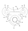
- the airbag which concerns on one Embodiment of this invention is shown, and it is a front view of a vent patch (3rd panel).
- 1 shows an airbag according to an embodiment of the present invention and is a front view of a tether cover.
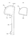
- the airbag which concerns on one Embodiment of this invention is shown, (A) is a front view of a vent cover, (B) is a front view of a patch member. It is a front view of the vent cover of the state which showed the airbag which concerns on one Embodiment of this invention, and attached the patch member.
- the airbag of the modification which concerns on one Embodiment of this invention is shown, (A) is a front view of a vent cover, (B) is a front view of a patch member.
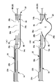
- FIG. 1 shows an airbag according to an embodiment of the present invention, in which (A) is a cross-sectional view of a main part before the airbag main body is inflated and deployed, and (B) is a main part before the airbag main body is inflated and deployed. It is sectional drawing of a part.
- FIG. 1 is an exploded perspective view of an airbag according to an embodiment of the present invention
- FIG. 2 shows an airbag according to an embodiment of the present invention, a front view of an assembled state of main parts
- FIG. The airbag which concerns on embodiment is shown, explanatory drawing of the relative positional relationship of a steering wheel and a vent hole
- FIG. 4 shows the airbag which concerns on one Embodiment of this invention, and is a front view of a vent patch (3rd panel)
- 5 shows an airbag according to an embodiment of the present invention, a front view of a tether cover
- FIG. 6 shows an airbag according to an embodiment of the present invention
- FIG. 6 (A) is a front view of a vent cover
- 6B is a front view of the patch member
- FIG. 7 shows an airbag according to an embodiment of the present invention, a front view of the vent cover with the patch member attached, and FIG. 8 is an embodiment of the present invention.
- FIG. 8 shows an airbag according to a modification according to FIG. 8A is a front view of the vent cover
- FIG. 8B is a front view of the patch member
- FIG. 9 is an airbag according to an embodiment of the present invention
- FIG. 9A is an airbag body inflated and deployed.
- FIG. 9B is a cross-sectional view of the main part in the state before the airbag body is inflated and deployed.
- the airbag 10 has a substantially perfect circle-shaped front panel 12 as a first panel located on the occupant facing side, and is positioned on the non-occupant facing side, having substantially the same diameter as the front panel 12. And a rear panel 14 as a second panel, and the peripheral portion thereof is joined by sewing or the like to constitute a bag-like airbag body 16.
- the front panel 12 as the first panel constitutes a surface that faces (confronts) an occupant in a state where the airbag body 16 is inflated and deployed, that is, a front surface (occupant reference) that the occupant actually contacts.
- the rear panel 14 constitutes a surface excluding the front panel 12 in the three-dimensional shape of the airbag body 16 when inflated and deployed in a bag shape, and includes a side surface such as a side surface (side panel or the like) depending on the three-dimensional shape. .
- the front panel 12 is provided with an expansion control member 18 near the center.
- the expansion control member 18 is integrally formed with a joining portion 18a joined to the center of the front panel 12 by sewing H1 (shown only by a two-dot chain line in FIG. 1) and a belt-like regulating portion 18b extending from the joining portion 18a. I have.
- a vent patch 20 as a substantially triangular third panel and a tether cover 22 are provided on the inner surface of the rear panel 14.
- a vent cover 24 and a patch member 26 are provided outside the rear panel 14.
- an inflator insertion hole 14a is formed near the center of the rear panel 14.
- a pair of vent holes 14b are formed in the rear panel 14 from the center to the upper (front) side of the vehicle body in the vehicle body installation state (steering wheel installation state).
- the vent hole 14b is formed so as to have an opening center in the radial direction from the center of the rear panel 14.
- the vent hole 14b extends along a center line (0 o'clock direction) extending in the longitudinal direction of the vehicle body of the steering wheel S.
- it is formed to be symmetrical in the direction of 2 o'clock and 10 o'clock on the basis of the clock short hand.
- the vent hole 14b is formed at the center of the rear panel 14, that is, at a position close to the inflator 30 of the inflator device, and is set so that exhaust can be performed from the initial stage of deployment.
- the pair of vent holes 14b are arranged in a space portion inside the wheel rim R of the steering wheel S and avoiding the spokes P extending from the vicinity of the center of the steering wheel S toward the wheel rim R.
- the vent hole 14b is disposed at a position where interference (overlap) between the opened air grid (not shown) formed in the steering wheel S and the vent hole 14b can be avoided.
- a pair of slits 14c are formed at positions close to the vent holes 14b.
- the vent patch 20 is formed of a cloth body made of the same material as that of the front panel 12 and the rear panel 14, and is formed in a substantially triangular shape with each corner portion being arc-shaped as shown in FIG.
- the vent patch 20 includes a second inflator insertion hole 20a that matches the inflator insertion hole 14a, a pair of vent holes 20b that matches the vent hole 14b, and a pair of slits 20c that match the slits 14c. ing.
- the vent patch 20 is joined to the rear panel 14 by sewing H2, H3, and H4 in an annular shape (perfect circle) so as to surround the second inflator insertion hole 20a, for example.
- the vent patch 20 is joined to the rear panel 14 by sewing H5 in an annular shape (perfect circle) so as to surround the vent hole 20b. Further, the vent patch 20 extends across the pair of slits 20c and is joined to the rear panel 14 by parallel sewing H6 and H7 so as to sandwich the slit 20c.
- the tether cover 22 is formed of a cloth body made of the same material as the front panel 12 and the rear panel 14, and as shown in FIG. 5, extends in the longitudinal direction of the vehicle body with a third inflator insertion hole 22a coinciding with the inflator insertion hole 14a. And a slit 22b located on the center line (0 o'clock direction).
- the tether cover 22 is formed in a different shape so as to avoid the vent hole 20b, and the slit 22b is formed so as to be positioned between the pair of slits 20c.
- the tether cover 22 is joined to the rear panel 14 integrally with the vent patch 20 (sewing H2, H3, H6, H7).
- the tether cover 22 covers the slit 20c of the vent patch 20 at both ends thereof, and the sealing performance is improved by closing the communication state with the outside through the slit 14c of the rear panel 14.
- the vent cover 24 includes a fan-shaped cover 24a (cover portion), a strip-shaped tether 24b extending from the cover 24a, and a joint that is positioned at the tip of the tether 24b and wider than the tether 24b. And a piece 24c.
- the vent cover 24 is provided individually corresponding to each vent hole 14b.
- the vent cover 24 is provided symmetrically to each other as shown in FIG. 1 by using the vent cover 24 having the same shape, size, and the like (inverted in the apparent mounting state).
- the pair of vent holes 14b are provided symmetrically with respect to the center line (0 o'clock direction).
- the pair of vent covers 24 are disposed symmetrically with respect to the center line of the rear panel 14 (airbag body 16).
- the arc-shaped peripheral edge portion of the cover 24a is joined to the rear panel 14 by sewing H8, and the hinge portion 28 is configured by the sewing H8.
- the hinge portion 28 is formed on the downstream side in the introduction direction (injection direction) of the pressure gas injected from the inflator 30 disposed at the center of the rear panel 14, that is, on the outer peripheral side of the rear panel 14. Therefore, it is preferable that the arc center of the hinge portion 28 is located on the extended line connecting the center of the rear panel 14 and the center of the vent hole 14b.
- the joining piece 24c is joined by sewing H9.
- the length of the tether 24b is set so as to define the opening degree of the cover 24a with reference to the slit 22b when the joining piece 24c is joined.
- the pair of tethers 24b are joined to the tip of the restricting portion 18b of the inflation control member 18 by sewing H9, so that the airbag body 16 is inflated and deployed according to the length of the both. Thickness is defined.
- the tether 24b which is one end of the vent cover 24, passes through the slit 20c and the slit 22b, so that the cloth body of the slit 20c is not easily stretched by the pressure gas ejected from the inflator 30, thereby reducing gas leakage.
- the patch member 26 is formed in a fan shape, and an opening 26a having a diameter smaller than the opening diameter of the vent hole 14b is formed at the center thereof.
- the patch member 26 is joined to the cover 24a by sewing H5 so as to surround the opening 26a.
- the patch member 36 is formed in a fan shape smaller than the cover 24a, and only the arc portion of the cover 24a is joined to the rear panel 14, and the arc portion of the patch member 36 and the cover 24a Are not joined, but two straight sides may be joined to the cover 24a by the sewing H10, and an arc portion (non-joined portion) that is not joined may be an opening that changes to the opening 26a.
- the vent cover 24 has the same shape and size as those shown in FIG. 6A, except that the sewing portion (joining portion) of the cover 24a is different.
- the cover 24a and the patch member 26 are positioned along the rear panel 14 when the inflator 30 is not operated as shown in FIG. 9A.
- the inflator 30 When the inflator 30 is activated and the pressure gas is supplied to the inside of the airbag body 16, a part of the pressure gas is about to be discharged from the vent hole 14b.
- the restricting portion 18b and the tether 24b are tensioned to generate a pulling force, and the opening degree of the cover 24a is restricted.
- a part of the pressure gas is supplied between the cover 24a and the patch member 26 from the opening 26a, and as shown in FIG. 9B, the cover 24a and the patch member 26 cooperate to expand,
- the vent hole 14b is pressed down while forming a pressure gas storage space K between the cover 24a and the patch member 26. Therefore, in addition to the restriction of the opening degree of the cover 24a due to the pulling force of the tether 24b described above, the cover 24a and the patch member 26 expand, whereby the degree of sealing of the vent hole 14b can be maintained high.
- the total length of the airbag body 16 with the tether 24b can define the thickness when the airbag body 16 is inflated, and the airbag body 16 is inflated and deployed to cause a pulling action on the tether 24b. 14b can be pressed in the closing direction.
- the tether 24b receives the load in the pulling direction along with the inflation and deployment of the airbag body 16 by being joined to the other end (the restricting portion 18b) of the inflation control member 18.
- the other end side of the tether 24b is introduced as it is between the vent patch 20 and the tether cover 22 from the slit 20c inside the airbag body 16, and therefore the slit 20c and the slit 14c. It is possible to control the tensile load (direction) along the surface direction of the cloth body without forcibly expanding the width. As a result, the pressure gas can be fully maintained.
- the slit 20 c and the slit 14 c are covered with a part of the tether cover 22. Therefore, even if the slit 20c and the slit 14c are forcibly pushed and expanded by the pressure load of the pressure gas or the tensile load of the cloth body due to the inflation and deployment of the airbag body 16, the slit 20c and the slit 14c from the inside of the airbag body 16 are forced. Can be closed. As a result, it is possible to further ensure the maintenance of the pressure gas.
- the other end side of the tether 24b is introduced between the vent patch 20 and the tether cover 22 so as to be a pressure gas.
- the space between the end of the tether cover 22 and the vent patch 20 is not opened in the counter direction (the portion not sewn) with respect to the injection direction of the pressure gas injected from the inflator 30, the pressure gas It does not enter between the tether cover 22 and the vent patch 20 as it is.
- the tether 24b is drawn into the airbag body 16 from the slit 14c formed in the vicinity of the vent hole 14b of the rear panel 14.
- the vent patch 20 and the tether cover 22 are then passed through.
- the tether 24b being covered with the tether cover 22 inside the airbag body in this way, when the airbag body 16 is inflated and deployed and the tether 24b of the vent cover 24 is pulled out, the influence of pressure gas and other components Can be made less susceptible to interference.
- the closing degree of the vent hole 14b can be controlled smoothly and accurately with a relatively simple and low-cost structure without performing complicated settings.
- a slit 20 c that coincides with the slit 14 c (first slit) formed in the rear panel 14 is formed near the end of the vent patch 20, and the slit is formed in the center of the tether cover 22. 22b (third slit) is formed.
- the tether 24 b passes through the slit 14 c of the rear panel 14 and the slit 20 c of the vent patch 20, passes between the vent patch 20 and the tether cover 22, and then passes through the slit 22 b of the tether cover 22. 16 is drawn to the inside.
- the slit 20c of the vent patch 20 is covered with the tether cover 22, so that the slit 20c and the slit 14c can be closed from the inside, and the cloth body in the vicinity of the slit 20c of the vent patch 20 can be closed. Pulling can be suppressed.
- the vent hole 14b is sandwiched between inflator attachment portions (respective inflator insertion holes 14a, 20a, 22a) formed in the center of the rear panel 14, and the steering wheel is inflated when the airbag body 16 is inflated and deployed.
- a pair is formed near the center of the rim R, and the vent cover 24 and the tether 24b are provided symmetrically with respect to the pair of vent holes 14b.
- the vent hole 14b is formed at a radially symmetric position about the inflator mounting portion.
- the steering wheel S is disposed in a space portion inside the wheel rim R and avoiding the spokes P extending from the vicinity of the center of the steering wheel S toward the wheel rim R.
- the vent hole 14b is disposed at a position where interference (overlap) between the opened air grid (not shown) formed in the steering wheel S and the vent hole 14b can be avoided.
- the opening and closing of the pair of vent covers 24 can be easily synchronized, and the opening degree (sealing degree) can be made uniform.
- one end (joint portion 18a) of the band-shaped expansion control member 18 is joined to the inner surface of the front panel 12, and both ends of the tether 24b are joined to the other end (regulation portion 18b) of the expansion control member 18. is doing. Accordingly, a pulling action is generated in the tether 24b when the airbag body 16 is inflated and deployed, and the vent cover 24 can be pressed in the closing direction of the vent hole 14b.
- one end of the expansion control member 18 is joined at the center of the front panel 12 so that the expansion control member 18 and the slit 22b of the tether cover 22 are positioned at the center (0 o'clock direction).
- the opening degree of the vent hole 14b can be made even easier.
Landscapes
- Engineering & Computer Science (AREA)
- Mechanical Engineering (AREA)
- Physics & Mathematics (AREA)
- Fluid Mechanics (AREA)
- Air Bags (AREA)
Description
本発明は、自動車等の衝突時に乗員を拘束するためのエアバッグ及びそれを利用したエアバッグ装置に関する。
従来、自動車の衝突、横転などの緊急時にインフレータが作動し、このインフレータから噴出された圧力ガスによって袋体に形成されたエアバッグが折り畳まれた状態から膨張展開し、乗員を拘束するエアバッグ装置が知られている。
エアバッグ装置に用いられるエアバッグには、膨張展開状態において少なくとも第1パネルと第2パネルとを有するように袋体に形成されたエアバッグ本体と、第2パネルに形成されたベントホールと、を備えている。このベントホールは、膨張展開したエアバッグ本体に乗員が接触したときに、ベントホールを介してエアバッグ本体の内部から圧力ガスを流出させる。これにより、乗員をエアバッグ本体によって円滑に受け止めることができる。
近年では、エアバッグ本体の内圧が所定以上となるまではベントホールが閉又は小開度となり、エアバッグの内圧が所定以上となるとともにエアバッグに乗員が接触したときにベントホールが開又は大開度となるように構成された、エアバッグが提案されている(例えば、特許文献1及び特許文献2参照)。
特許文献1に開示の技術は、エアバッグの膨張展開時に、ベントホールの外側に設けた開閉部材を、エアバッグ内部を通したテザーによって開閉する。したがって、ベントホールを開閉する際にテザーの動作挙動が圧力ガスの影響を受けやすく、ベントホールの閉度を円滑かつ高精度に制御することが容易ではない。この結果、エアバッグ本体の内圧を高精度に確保するために、エアバッグ本体の容積を小さくしたり、インフレータから噴出される圧力ガスの噴出能力を高くするなどの複雑な設定が必要となっていた。
特許文献2に開示の技術は、ベントホールの開度を調整するための専用の開閉装置を必要とする。この結果、上記開閉装置を設置するためのスペース確保のためにエアバッグ装置の大型化、さらにはエアバッグ装置の高コスト化を招く。
本発明の目的は、複雑な設定を行うことなく、比較的簡素かつ低コストな構造で、ベントホールの閉度を円滑かつ高精度に制御できるエアバッグ及びエアバッグ装置を提供することを目的とする。
上記目的を達成するために、本願第1発明のエアバッグは、膨張展開状態において少なくとも乗員対向側の第1パネルと非乗員対向側の第2パネルとを有するように袋体に形成されたエアバッグ本体と、前記第2パネルに形成されたベントホールと、前記第2パネルの外面に取り付けられてカバー部によって前記ベントホールを開閉するベントカバーと、前記第2パネルの前記ベントホールの近傍に形成された第1スリットと、前記ベントカバーに設けられ、一方側が前記カバー部に接続されるとともに、他方側が前記第1スリットを介し前記エアバッグ本体の外部から内部へと引き入れられるように配置されるテザーと、前記第2パネルの内面側に取り付けられたテザーカバーと、を備え、前記テザーは、前記内部へと引き入れられた前記他方側の少なくとも一部が前記第2パネルと前記テザーカバーとの間に引き通されていることを特徴とする。
第1発明のエアバッグは、エアバッグ本体が膨張展開状態において少なくとも第1パネルと第2パネルとを有するように袋体に形成され、ベントホールが第2パネルに形成され、ベントホールを開閉するベントカバーが第2パネルの外面に取り付けられている。
ここで、エアバッグ本体は、自動車の衝突、横転などの緊急時にインフレータが作動し、このインフレータから噴出される圧力ガスによって袋体に形成されたエアバッグが折り畳まれた状態から袋状に膨張展開し、膨張展開したエアバッグ本体に乗員が接触したときに、乗員を受け止める(拘束する)ことができる。
また、第1発明のエアバッグでは、エアバッグ本体の膨張展開初期から膨張展開完了までの間は、ベントカバーによってベントホールの開度を開状態から閉状態まで調整することができる。そして、エアバッグ本体が膨張展開完了した状態では、ベントカバーによってベントホールを閉状態とすることができ、エアバッグ本体の内圧を維持することができる。この際、ベントカバーのテザーはエアバッグ本体の内部へと引き入れられた後に、そのうち少なくとも一部が第2パネルとテザーカバーとの間に引き通される。このようにテザーの他方側の少なくとも一部がエアバッグ本体の内部においてテザーカバーによって覆われる結果、エアバッグ本体が膨張展開してベントカバーのテザーが引き出される際に、圧力ガスの影響や他の構成部品との干渉を受け難くすることができる。この結果、ベントカバーは、テザーによる引き出し調整のみの複雑な設定を行うことなく、比較的簡素かつ低コストな構造で、ベントホールの閉度を円滑かつ高精度に制御することができる。
第2発明のエアバッグは、第1発明に記載のエアバッグにおいて、前記第2パネルと前記テザーカバーとの間で前記第2パネルの内面に取り付けられた第3パネルを備え、前記第3パネルの端部付近に前記第1スリットと一致して前記テザーの前記他方側を前記エアバッグ本体の外部から内部へと引き入れるための第2スリットが形成され、前記テザーは、前記内部へと引き入れられた前記他方側の少なくとも一部が前記第3パネルと前記テザーカバーとの間に引き通されていることを特徴とする。
第2発明のエアバッグは、第3パネルが第2パネルとテザーカバーとの間に位置して第2パネルの内面に取り付けられている。第3パネルには、第2パネルの第1スリットと一致する位置に第2スリットが形成されている。したがって、テザーの他方側は、第1スリットと第2スリットとを貫通した状態で、少なくともその一部を第3パネルとテザーカバーとの間に引き通すことができる。
このように、第2発明のエアバッグによれば、テザーの他方側の少なくとも一部がエアバッグ本体の内部においてテザーカバーによって覆われる結果、エアバッグ本体が膨張展開してベントカバーのテザーが引き出される際に、圧力ガスの影響や他の構成部品との干渉を受け難くすることができる。この結果、複雑な設定を行うことなく、比較的簡素かつ低コストな構造で、ベントホールの閉度を円滑かつ高精度に制御することができる。
第3発明のエアバッグは、第1発明に記載のエアバッグにおいて、前記テザーカバーの中央に第3スリットが形成され、前記テザーは、前記第1スリットを貫通したうえで、前記第2パネルと前記テザーカバーとの間を経由した後に、前記第3スリットから前記エアバック本体内へと引き出されていることを特徴とする。また、第4発明のエアバッグは、第2発明に記載のエアバッグにおいて、前記テザーカバーの中央に第3スリットが形成され、前記テザーは、前記第1スリットと前記第2スリットとを貫通したうえで、前記第3パネルと前記テザーカバーとの間を経由した後に、前記第3スリットから前記エアバック本体内へと引き出されていることを特徴とする。
第3発明及び第4発明のエアバッグによれば、テザーの他方側のうち、例えば、インフレータの近傍で圧力ガスの噴出方向と交差する方向に延在する部位があった場合、その部位をエアバッグ本体の内部においてテザーカバーによって覆うことにより、エアバッグ本体が膨張展開してベントカバーのテザーが引き出される際に、圧力ガスの影響や他の構成部品との干渉を受け難くすることができる。この結果、複雑な設定を行うことなく、比較的簡素かつ低コストな構造で、ベントホールの閉度を円滑かつ高精度に制御することができる。
第5発明のエアバッグは、第3発明又は第4発明に記載のエアバッグにおいて、前記第1スリット又は前記第2スリットを前記テザーカバーで覆ったことを特徴とする。これにより、第1スリット又は第2スリットを内側から塞ぐことができるうえ、第1スリット又は第2スリットの近傍の布体の引っ張りを抑制することができる。
第6発明のエアバッグは、第3発明に記載のエアバッグにおいて、前記ベントホールは、前記第2パネルの中央に形成したインフレータ取付部を挟み、かつ、前記エアバッグ本体を膨張展開した際にステアリングホイールリムの内側となる中心寄りに一対形成され、前記ベントカバーと前記テザーとは、前記一対のベントホールに対して対称となるように一対設けられていることを特徴とする。これにより、例えば乗員(運転手)が接近している姿勢のときにエアバッグ本体が膨張展開を開始しても、折り畳まれた状態からベントホールを早期に露出させることができ、その初期から容易に排気を行うことが可能となる。
第7発明のエアバッグは、第6発明に記載のエアバッグにおいて、前記一対のベントホールは、前記インフレータ取付部を中心として放射方向対称位置に形成されていることを特徴とする。また、第8発明のエアバッグは、第7発明に記載のエアバッグにおいて、前記ステアリングホイールリムよりも内側の空間部分で、かつ前記ステアリングホイールの中心付近から前記ステアリングホイールリムに向って放射状に延びるステアリングスポークを避けた位置で、かつ、前記エアバッグ本体を膨張展開するために前記ステアリングホイールに形成された開放後のエアバッグリッドと前記ベントホールとの干渉(重なり)を避ける位置に配置されていることを特徴とする。
第9発明のエアバッグは、第6発明に記載のエアバッグにおいて、前記テザーの両端を互いに接合したことを特徴とする。これにより、一対のベントカバーの開閉を容易に同期させることができ、その開度(密閉度)を均一化することができる。
第10発明のエアバッグは、第9発明に記載のエアバッグにおいて、前記第1パネルの内面に帯状の膨張制御部材の一端を接合し、前記テザーの両端を前記膨張制御部材の他端と接合したことを特徴とする。これにより、エアバッグ本体の膨張展開時にテザーに引っ張り作用が発生し、ベントカバーをベントホールの閉じ方向に押さえ付けることができる。
第11発明のエアバッグは、第10発明に記載のエアバッグにおいて、前記膨張制御部材の前記一端を前記第1パネルの中心で接合したことを特徴とする。これにより、膨張制御部材とテザーカバーのスリットとが中心(0時方向)に位置し、一対のベントホールの開度をより一層容易に均一化することができる。
第12発明のエアバッグ装置は、第1発明のエアバッグと、前記エアバッグに圧力ガスを供給するインフレータと、を備えていることを特徴とする。
本発明のエアバッグ及びエアバッグ装置は、安価でしかも簡素な構成であっても、エアバッグ本体が膨張展開してベントカバーのテザーが引き出される際に圧力ガスの影響や他の構成部品との干渉を受け難くすることができる。
次に、本発明の一実施形態に係るエアバッグ及びエアバッグ装置について、図面を参照して説明する。
図1は本発明の一実施形態に係るエアバッグの分解斜視図、図2は本発明の一実施形態に係るエアバッグを示し、要部の組み付け状態の正面図、図3は本発明の一実施形態に係るエアバッグを示し、ステアリングホイールとベントホールとの相対位置関係の説明図、図4は本発明の一実施形態に係るエアバッグを示し、ベントパッチ(第3パネル)の正面図、図5は本発明の一実施形態に係るエアバッグを示し、テザーカバーの正面図、図6は本発明の一実施形態に係るエアバッグを示し、図6(A)はベントカバーの正面図、図6(B)はパッチ部材の正面図、図7は本発明の一実施形態に係るエアバッグを示し、パッチ部材を取り付けた状態のベントカバーの正面図、図8は本発明の一実施形態に係る変形例のエアバッグを示し、図8(A)はベントカバーの正面図、図8(B)はパッチ部材の正面図、図9は本発明の一実施形態に係るエアバッグを示し、図9(A)はエアバッグ本体が膨張展開する前の状態の要部の断面図、図9(B)はエアバッグ本体が膨張展開する前の状態の要部の断面図である。
図1及び図2において、エアバッグ10は、乗員対向側に位置する第1パネルとしての略真円形状のフロントパネル12と、フロントパネル12と略同一径とされて非乗員対向側に位置する第2パネルとしてのリヤパネル14と、を備え、その周縁部を縫製等によって接合することで袋状のエアバッグ本体16を構成している。なお、第1パネルとしてのフロントパネル12は、エアバッグ本体16が膨張展開した状態において乗員と対向(対峙)する面、すなわち、乗員が実際に接触する正面(乗員基準)を構成する。また、リヤパネル14は、袋状に膨張展開した際のエアバッグ本体16の立体形状におけるフロントパネル12を除く面を構成し、その立体形状によっては、側面(サイドパネル等)等の側面を含むものとする。
フロントパネル12には、中央付近に膨張制御部材18が設けられている。この膨張制御部材18は、フロントパネル12の中央に縫製H1(図1にのみ二点鎖線で図示)により接合される接合部18aと、接合部18aから延びる帯状の規制部18bと、を一体に備えている。
リヤパネル14の内面には、略三角形状の第3パネルとしてのベントパッチ20と、テザーカバー22と、が設けられている。また、リヤパネル14の外側には、ベントカバー24と、パッチ部材26と、が設けられている。
リヤパネル14の中心付近にはインフレータ挿入穴14aが形成されている。リヤパネル14には、その中心から車体設置状態(ステアリングホイール設置状態)において車体上方(前方)側に一対のベントホール14bが形成されている。ベントホール14bは、リヤパネル14の中心から放射方向に開口中心を有するように形成されており、例えば、図3に示すように、ステアリングホイールSの車体前後方向に延びる中心線(0時方向)に対して時計短針基準で2時と10時の方向に対称となるように形成されている。なお、ベントホール14bは、リヤパネル14の中心、すなわち、インフレータ装置のインフレータ30に対して近接した位置に形成されており、展開初期から排気が可能となるように設定されている。この際、一対のベントホール14bは、ステアリングホイールSのホイールリムRよりも内側で、ステアリングホイールSの中心付近からホイールリムRに向かって伸びるスポークPを避けた空間部分に配置される。さらに、ベントホール14bは、ステアリングホイールSに形成された開放後のエアバッグリッド(図示せず)とベントホール14bとの干渉(重なり)を避けることができる位置に配置されている。リヤパネル14には、各ベントホール14bに近接した位置に一対のスリット14cが形成されている。
ベントパッチ20は、フロントパネル12及びリヤパネル14と同じ材質の布体から形成されており、図4に示すように、各角部を円弧状とした略三角形状に形成されている。ベントパッチ20は、上述したインフレータ挿入穴14aと一致する第2インフレータ挿入穴20aと、ベントホール14bと一致する一対のベントホール20bと、各スリット14cに一致する一対のスリット20cと、が形成されている。ベントパッチ20は、例えば、第2インフレータ挿入穴20aを取り巻くように環状(真円)にリヤパネル14に縫製H2,H3,H4により接合されている。また、ベントパッチ20は、ベントホール20bを取り巻くように環状(真円)にリヤパネル14に縫製H5により接合されている。さらに、ベントパッチ20は、一対のスリット20cに跨るように延在されるとともに、スリット20cを挟むように並行な縫製H6,H7によってリヤパネル14に接合されている。
テザーカバー22は、フロントパネル12及びリヤパネル14と同じ材質の布体から形成されており、図5に示すように、インフレータ挿入穴14aと一致する第3インフレータ挿入穴22aと、車体前後方向に延びる中心線(0時方向)上に位置するスリット22bと、が形成されている。なお、テザーカバー22は、ベントホール20bを避けるように異型に形成されており、スリット22bは一対のスリット20cの間に位置するように形成されている。テザーカバー22は、ベントパッチ20と一体にリヤパネル14に接合(縫製H2,H3,H6,H7)されている。テザーカバー22は、その両端部でベントパッチ20のスリット20cを覆っており、リヤパネル14のスリット14cを介して外部との連通状態を塞ぐことで密閉性を向上している。
ベントカバー24は、図6(A)に示すように、扇状のカバー24a(カバー部)と、カバー24aから延びる帯状のテザー24bと、テザー24bの先端に位置してテザー24bよりも幅広の接合片24cと、を備えている。なお、ベントカバー24は、各ベントホール14bに対応して個々に設けられている。この際、ベントカバー24は、その形状や大きさ等を同一(見掛け上の取り付け状態で表裏反転)にしたものを用いることにより、図1に示すように、互いに対称に設けられる。本実施の形態では、一対のベントホール14bを、中心線(0時方向)に対して対称に設けている。したがって、一対のベントカバー24は、リヤパネル14(エアバッグ本体16)の中心線に対しても対称に配置されている。ベントカバー24は、カバー24aの円弧状周縁部が縫製H8によってリヤパネル14に接合されており、その縫製H8によってヒンジ部28を構成している。ここで、ヒンジ部28は、リヤパネル14の中心に配置されるインフレータ30から噴射される圧力ガスの導入方向(噴射方向)下流側、すなわち、リヤパネル14の外周側に形成されている。したがって、ヒンジ部28の円弧中心は、リヤパネル14の中心とベントホール14bの中心とを結ぶ線の延長線上に位置するのが好ましい。テザー24bは、スリット14c及びスリット20cに挿入された後、ベントパッチ20とテザーカバー22との間(縫製H6と縫製H7との間)を経由してスリット22bから引き出された後、各両端の接合片24cが縫製H9によって接合されている。テザー24bの長さは、その接合片24cを接合したときのスリット22bを基準としてカバー24aの開度を規定するように設定されている。また、一対のテザー24bは、膨張制御部材18の規制部18bの先端と縫製H9によって接合することによって、その両者の長さに応じてエアバッグ本体16が膨張展開したときのエアバッグ本体16の厚さが規定される。また、ベントカバー24の一端であるテザー24bは、スリット20c及びスリット22bを通すことで、インフレータ30から噴出された圧力ガスによってスリット20cの布体が伸び難く、ガス漏れを軽減している。
パッチ部材26は、図6(B)に示すように、扇状に形成されており、その中心にはベントホール14bの開口径よりも小径な開口26aが形成されている。本実施の形態では、図7に示すように、パッチ部材26は開口26aを取り巻くように縫製H5によってカバー24aに接合されている。
図8(A),(B)に示すように、パッチ部材36をカバー24aよりも小さい扇状に形成し、カバー24aの円弧部分のみリヤパネル14に接合し、パッチ部材36の円弧部分とカバー24aとは接合せず、直線状の2辺をカバー24aと縫製H10によって接合し、接合しなかった円弧部分(非接合部)を開口26aに変わる開口としても良い。なお、ベントカバー24は、カバー24aの縫製部分(接合部分)が異なるのみで、形状や大きさ等は、図6(A)に示したものと同一である。
上記の構成において、図9(A)に示すように、インフレータ30が作動していない収納状態では、カバー24aとパッチ部材26とはリヤパネル14に沿うように位置している。
インフレータ30が作動して、その圧力ガスがエアバッグ本体16の内部に供給されると、その一部がベントホール14bから外部に放出されようとする。ここで、エアバッグ本体16が膨張するにつれて規制部18bとテザー24bとが緊張して引っ張り力が発生し、カバー24aの開度が規制される。また、圧力ガスの一部は、開口26aからカバー24aとパッチ部材26との間に供給され、図9(B)に示すように、カバー24aとパッチ部材26とが協働して膨張し、カバー24aとパッチ部材26との間に圧力ガス貯留用の空間Kを形成しつつ、ベントホール14bを押さえ込む。したがって、上述したテザー24bの引っ張り力によるカバー24aの開度規制に加えて、カバー24aとパッチ部材26とが膨張することにより、ベントホール14bの密閉度を高く維持することができる。
また、エアバッグ本体16の膨張展開時の厚さを規定する膨張制御部材18の他端(規制部18b)とテザー24bの両端(接合片24c)とを接合したことにより、これら規制部18bとテザー24bとの全体の長さでエアバッグ本体16の膨張時の厚さを規定することができると共に、エアバッグ本体16の膨張展開によってテザー24bに引っ張り作用が発生し、ベントカバー24をベントホール14bの閉じ方向に押さえ付けることができる。
ここで、テザー24bは、膨張制御部材18の他端(規制部18b)と接合したことにより、エアバッグ本体16の膨張展開と共に引っ張り方向の荷重を受ける。
しかしながら、本実施の形態においては、テザー24bの他端側は、スリット20cからエアバッグ本体16の内部においてそのままベントパッチ20とテザーカバー22との間に導入されているため、スリット20c及びスリット14cを強制的に広げることなく引っ張り荷重(方向)を布体の面方向に沿うように制御することができる。これにより圧力ガスの保持に万全を期すことができる。
しかも、スリット20cとスリット14cとは、テザーカバー22の一部によって覆われている。したがって、圧力ガスの圧力荷重やエアバッグ本体16の膨張展開による布体の引っ張り荷重によってスリット20cとスリット14cとが強制的に押し広げられても、エアバッグ本体16の内側からスリット20cとスリット14cとを塞ぐことが可能となる。これにより圧力ガスの保持にさらに万全を期すことができる。但し、スリット20cとスリット14cとは、テザーカバー22の一部によって覆われていなくても、上記したテザー24bの他端側がベントパッチ20とテザーカバー22との間に導入される構成によって圧力ガスの保持に万全を期すことができる。さらに、インフレータ30から噴射される圧力ガスの噴射方向に対してテザーカバー22の端部とベントパッチ20との間がカウンタ方向に開口(縫製していない部分)していないことから、圧力ガスがそのままテザーカバー22とベントパッチ20との間入り込んでしまうこともない。
以上説明したように、本実施形態のエアバッグ10を備えたエアバッグ装置では、テザー24bが、リヤパネル14のベントホール14bの近傍に形成したスリット14cからエアバッグ本体16の内部へと引き入れられた後、ベントパッチ20とテザーカバー22との間に引き通されている。このようにテザー24bがエアバッグ本体の内部においてテザーカバー22によって覆われる結果、エアバッグ本体16が膨張展開してベントカバー24のテザー24bが引き出される際に、圧力ガスの影響や他の構成部品との干渉を受け難くすることができる。この結果、複雑な設定を行うことなく、比較的簡素かつ低コストな構造で、ベントホール14bの閉度を円滑かつ高精度に制御することができる。
また、本実施形態では特に、ベントパッチ20の端部付近に、リヤパネル14に形成したスリット14c(第1スリット)と一致するスリット20c(第2スリット)を形成し、テザーカバー22の中央にスリット22b(第3スリット)を形成している。そして、テザー24bは、リヤパネル14のスリット14cとベントパッチ20のスリット20cとを貫通したうえで、ベントパッチ20とテザーカバー22との間を経由した後に、テザーカバー22のスリット22bからエアバッグ本体16の内部へと引き出されている。これにより、圧力ガスの圧力が高い近傍であっても、その圧力によってテザー24bの途中部分が流されて端部側が引っ張られる(引き込まれる)といった悪影響を抑制することができる。
また、本実施形態では特に、ベントパッチ20のスリット20cをテザーカバー22で覆ったことにより、スリット20c及びスリット14cを内側から塞ぐことができるうえ、ベントパッチ20のスリット20cの近傍の布体の引っ張りを抑制することができる。
また、本実施形態では特に、ベントホール14bを、リヤパネル14の中央に形成したインフレータ取付部(各インフレータ挿入穴14a,20a,22a)を挟むとともに、エアバッグ本体16を膨張展開した際にステアリングホイールリムRの内側となる中心寄りに一対形成し、ベントカバー24とテザー24bとを一対のベントホール14bに対して対称に設けている。これにより、例えば乗員(運転手)が接近している姿勢のときにエアバッグ本体16が膨張展開を開始しても、折り畳まれた状態からベントホール14bを早期に露出させることができ、その初期から容易に排気を行うことが可能となる。
また、本実施形態では特に、ベントホール14bは、インフレータ取付部を中心として放射方向対称位置に形成されている。特に、この例ではステアリングホイールSのホイールリムRよりも内側で、ステアリングホイールSの中心付近からホイールリムRに向かって伸びるスポークPを避けた空間部分に配置される。さらに、ベントホール14bは、ステアリングホイールSに形成された開放後のエアバッグリッド(図示せず)とベントホール14bとの干渉(重なり)を避けることができる位置に配置されている。
また、本実施形態では特に、テザー24bの両端を互いに接合したことにより、一対のベントカバー24の開閉を容易に同期させることができ、その開度(密閉度)を均一化することができる。
また、本実施形態では特に、フロントパネル12の内面に帯状の膨張制御部材18の一端(接合部18a)を接合し、テザー24bの両端を膨張制御部材18の他端(規制部18b)と接合している。これにより、エアバッグ本体16の膨張展開時にテザー24bに引っ張り作用が発生し、ベントカバー24をベントホール14bの閉じ方向に押さえ付けることができる。
また、本実施形態では特に、膨張制御部材18の一端をフロントパネル12の中心で接合したことにより、膨張制御部材18とテザーカバー22のスリット22bとが中心(0時方向)に位置し、一対のベントホール14bの開度をより一層容易に均一化することができる。
10 エアバッグ
12 フロントパネル(第1パネル)
14 リヤパネル(第2パネル)
14a インフレータ挿入穴(インフレータ取付部)
14b ベントホール
14c スリット(第1スリット)
16 エアバッグ本体
18 膨張制御部材
18a 接合部
18b 規制部
20 ベントパッチ(第3パネル)
20a 第2インフレータ挿入穴
20b ベントホール
20c スリット(第2スリット)
22 テザーカバー
22a 第3インフレータ挿入穴
22b スリット(第3スリット)
24 ベントカバー
24a カバー部
24b テザー
24c 接合片
26 パッチ部材
26a 開口
28 ヒンジ部
30 インフレータ
H1~H10 縫製
12 フロントパネル(第1パネル)
14 リヤパネル(第2パネル)
14a インフレータ挿入穴(インフレータ取付部)
14b ベントホール
14c スリット(第1スリット)
16 エアバッグ本体
18 膨張制御部材
18a 接合部
18b 規制部
20 ベントパッチ(第3パネル)
20a 第2インフレータ挿入穴
20b ベントホール
20c スリット(第2スリット)
22 テザーカバー
22a 第3インフレータ挿入穴
22b スリット(第3スリット)
24 ベントカバー
24a カバー部
24b テザー
24c 接合片
26 パッチ部材
26a 開口
28 ヒンジ部
30 インフレータ
H1~H10 縫製
Claims (12)
- 膨張展開状態において少なくとも乗員対向側の第1パネル(12)と非乗員対向側の第2パネル(14)とを有するように袋体に形成されたエアバッグ本体(16)と、
前記第2パネル(14)に形成されたベントホールと、
前記第2パネル(14)の外面に取り付けられてカバー部(24a)によって前記ベントホール(14b)を開閉するベントカバー(24)と、
前記第2パネル(14)の前記ベントホール(14b)の近傍に形成された第1スリット(14c)と、
前記ベントカバー(24)に設けられ、一方側が前記カバー部(24a)に接続されるとともに、他方側が前記第1スリット(14c)を介し前記エアバッグ本体(16)の外部から内部へと引き入れられるように配置されるテザー(24b)と、
前記第2パネル(14)の内面側に取り付けられたテザーカバー(22)と、を備え、
前記テザー(24b)は、前記内部へと引き入れられた前記他方側の少なくとも一部が前記第2パネル(14)と前記テザーカバー(22)との間に引き通されている
ことを特徴とするエアバッグ(10)。 - 請求項1に記載のエアバッグ(10)において、
前記第2パネル(14)と前記テザーカバー(22)との間で前記第2パネル(14)の内面に取り付けられた第3パネル(20)を備え、
前記第3パネル(20)の端部付近に前記第1スリット(14c)と一致して前記テザー(24b)の前記他方側を前記エアバッグ本体(16)の外部から内部へと引き入れるための第2スリット(20c)が形成され、
前記テザー(24b)は、前記内部へと引き入れられた前記他方側の少なくとも一部が前記第3パネル(20)と前記テザーカバー(22)との間に引き通されている
ことを特徴とするエアバッグ(10)。 - 請求項1に記載のエアバッグ(10)において、
前記テザーカバー(22)の中央に第3スリット(22b)が形成され、
前記テザー(24b)は、
前記第1スリット(14c)を貫通したうえで、前記第2パネル(14)と前記テザーカバー(22)との間を経由した後に、前記第3スリット(22b)から前記エアバック本体(16)内へと引き出されている
ことを特徴とするエアバッグ(10)。 - 請求項2に記載のエアバッグ(10)において、
前記テザーカバー(22)の中央に第3スリット(22b)が形成され、
前記テザー(24b)は、
前記第1スリット(14c)と前記第2スリット(20c)とを貫通したうえで、前記第3パネル(20)と前記テザーカバー(22)との間を経由した後に、前記第3スリット(22b)から前記エアバック本体(16)内へと引き出されている
ことを特徴とするエアバッグ(10)。 - 請求項3又は請求項4に記載のエアバッグ(10)において、
前記第1スリット(14c)又は前記第2スリット(20c)を前記テザーカバー(22)で覆った
ことを特徴とするエアバッグ(10)。 - 請求項3に記載のエアバッグ(10)において、
前記ベントホール(14b)は、
前記第2パネル(14)の中央に形成したインフレータ取付部(14a)を挟み、かつ、前記エアバッグ本体(16)を膨張展開した際にステアリングホイールリム(R)の内側となる中心寄りに一対形成され、
前記ベントカバー(24)と前記テザー(24b)とは、
前記一対のベントホール(14b)に対して対称となるように一対設けられている
ことを特徴とするエアバッグ(10)。 - 請求項6に記載のエアバッグ(10)において、
前記一対のベントホール(14b)は、前記インフレータ取付部(14a)を中心として放射方向対称位置に形成されている
ことを特徴とするエアバッグ(10)。 - 請求項7に記載のエアバッグ(10)において、
前記一対のベントホール(14b)は、
前記ステアリングホイールリム(R)よりも内側の空間部分で、かつ前記ステアリングホイール(S)の中心付近から前記ステアリングホイールリム(R)に向って放射状に延びるステアリングスポーク(P)を避けた位置で、かつ、前記エアバッグ本体(16)を膨張展開するために前記ステアリングホイール(S)に形成された開放後のエアバッグリッドと前記ベントホール(14b)との干渉を避ける位置に配置されている
ことを特徴とするエアバッグ(10)。 - 請求項6に記載のエアバッグ(10)において、
前記テザー(24b)の両端を互いに接合した
ことを特徴とするエアバッグ(10)。 - 請求項9に記載のエアバッグ(10)において、
前記第1パネル(12)の内面に帯状の膨張制御部材(18)の一端を接合し、
前記テザー(24b)の両端を前記膨張制御部材(18)の他端(18b)と接合した
ことを特徴とするエアバッグ(10)。 - 請求項10に記載のエアバッグ(10)において、
前記膨張制御部材(18)の前記一端を前記第1パネル(12)の中心で接合した
ことを特徴とするエアバッグ(10)。 - 請求項1に記載のエアバッグ(10)と、
前記エアバッグ(10)に圧力ガスを供給するインフレータ(30)と、
を備えている
ことを特徴とするエアバッグ装置。
Priority Applications (1)
| Application Number | Priority Date | Filing Date | Title |
|---|---|---|---|
| US14/430,102 US9434345B2 (en) | 2012-09-21 | 2013-09-10 | Airbag and airbag device |
Applications Claiming Priority (2)
| Application Number | Priority Date | Filing Date | Title |
|---|---|---|---|
| JP2012208902A JP5941803B2 (ja) | 2012-09-21 | 2012-09-21 | エアバッグ及びエアバッグ装置 |
| JP2012-208902 | 2012-09-21 |
Publications (1)
| Publication Number | Publication Date |
|---|---|
| WO2014045944A1 true WO2014045944A1 (ja) | 2014-03-27 |
Family
ID=50341258
Family Applications (1)
| Application Number | Title | Priority Date | Filing Date |
|---|---|---|---|
| PCT/JP2013/074397 Ceased WO2014045944A1 (ja) | 2012-09-21 | 2013-09-10 | エアバッグ及びエアバッグ装置 |
Country Status (3)
| Country | Link |
|---|---|
| US (1) | US9434345B2 (ja) |
| JP (1) | JP5941803B2 (ja) |
| WO (1) | WO2014045944A1 (ja) |
Families Citing this family (11)
| Publication number | Priority date | Publication date | Assignee | Title |
|---|---|---|---|---|
| US8523220B1 (en) | 2012-03-19 | 2013-09-03 | Amsafe, Inc. | Structure mounted airbag assemblies and associated systems and methods |
| US9580039B2 (en) | 2014-04-22 | 2017-02-28 | Autoliv Asp, Inc. | Multi-chamber airbag with unidirectional vent |
| US9944245B2 (en) | 2015-03-28 | 2018-04-17 | Amsafe, Inc. | Extending pass-through airbag occupant restraint systems, and associated systems and methods |
| US9925950B2 (en) | 2015-04-11 | 2018-03-27 | Amsafe, Inc. | Active airbag vent system |
| US9533652B1 (en) * | 2015-07-14 | 2017-01-03 | Autoliv Asp, Inc. | One-directional valve for multi-chamber airbags |
| US10093270B2 (en) * | 2016-01-13 | 2018-10-09 | Autoliv Asp, Inc. | Multi-flap vents for inflatable chambers |
| US10604259B2 (en) | 2016-01-20 | 2020-03-31 | Amsafe, Inc. | Occupant restraint systems having extending restraints, and associated systems and methods |
| US10293777B2 (en) | 2016-08-26 | 2019-05-21 | Autoliv Asp, Inc. | Multi-cushion airbag assemblies for reducing rotational velocity of an occupant's head |
| KR102324152B1 (ko) * | 2017-04-16 | 2021-11-09 | 아우토리브 디벨롭먼트 아베 | 에어백 장치 |
| US10766449B2 (en) * | 2018-11-28 | 2020-09-08 | Key Safety Systems, Inc. | Airbag module assembly |
| US11198411B2 (en) * | 2019-04-18 | 2021-12-14 | Autoliv Asp. Inc. | Energy-absorbing airbag diffusers and related airbag assemblies |
Citations (3)
| Publication number | Priority date | Publication date | Assignee | Title |
|---|---|---|---|---|
| JP2001277991A (ja) * | 2000-03-31 | 2001-10-10 | Takata Corp | エアバッグ |
| JP2008179337A (ja) * | 2006-08-04 | 2008-08-07 | Takata Corp | エアバッグ及びエアバッグ装置 |
| JP2010070016A (ja) * | 2008-09-17 | 2010-04-02 | Honda Motor Co Ltd | エアバッグ袋体 |
Family Cites Families (12)
| Publication number | Priority date | Publication date | Assignee | Title |
|---|---|---|---|---|
| JPH0811657A (ja) | 1994-06-29 | 1996-01-16 | Toyoda Gosei Co Ltd | エアバッグ装置のエアバッグ |
| JP3456616B2 (ja) | 1995-11-22 | 2003-10-14 | スズキ株式会社 | エアバッグ装置 |
| JP2005297715A (ja) | 2004-04-09 | 2005-10-27 | Takata Corp | エアバッグ及びエアバッグ装置 |
| EP1757495B1 (en) * | 2005-08-24 | 2008-05-21 | Takata Corporation | Airbag and airbag apparatus |
| JP5140072B2 (ja) | 2007-05-01 | 2013-02-06 | タカタ株式会社 | エアバッグ及びエアバッグ装置 |
| JP5166779B2 (ja) | 2007-06-18 | 2013-03-21 | タカタ株式会社 | エアバッグ、エアバッグ装置及びエアバッグの排気方法 |
| JP5127343B2 (ja) * | 2007-07-26 | 2013-01-23 | タカタ株式会社 | エアバッグ及びエアバッグ装置 |
| JP2009143374A (ja) | 2007-12-13 | 2009-07-02 | Takata Corp | エアバッグ及びエアバッグ装置 |
| JP4992853B2 (ja) * | 2008-08-06 | 2012-08-08 | タカタ株式会社 | エアバッグ装置 |
| US8419055B2 (en) * | 2008-09-17 | 2013-04-16 | Honda Motor Co., Ltd. | Airbag and method of manufacturing same |
| JP4892029B2 (ja) * | 2009-04-01 | 2012-03-07 | 本田技研工業株式会社 | 車両用エアバッグ装置 |
| JP2011098701A (ja) * | 2009-11-09 | 2011-05-19 | Takata Corp | エアバック装置 |
-
2012
- 2012-09-21 JP JP2012208902A patent/JP5941803B2/ja not_active Expired - Fee Related
-
2013
- 2013-09-10 WO PCT/JP2013/074397 patent/WO2014045944A1/ja not_active Ceased
- 2013-09-10 US US14/430,102 patent/US9434345B2/en not_active Expired - Fee Related
Patent Citations (3)
| Publication number | Priority date | Publication date | Assignee | Title |
|---|---|---|---|---|
| JP2001277991A (ja) * | 2000-03-31 | 2001-10-10 | Takata Corp | エアバッグ |
| JP2008179337A (ja) * | 2006-08-04 | 2008-08-07 | Takata Corp | エアバッグ及びエアバッグ装置 |
| JP2010070016A (ja) * | 2008-09-17 | 2010-04-02 | Honda Motor Co Ltd | エアバッグ袋体 |
Also Published As
| Publication number | Publication date |
|---|---|
| JP2014061824A (ja) | 2014-04-10 |
| US20150266447A1 (en) | 2015-09-24 |
| JP5941803B2 (ja) | 2016-06-29 |
| US9434345B2 (en) | 2016-09-06 |
Similar Documents
| Publication | Publication Date | Title |
|---|---|---|
| JP5941803B2 (ja) | エアバッグ及びエアバッグ装置 | |
| JP5976479B2 (ja) | エアバッグ及びエアバッグ装置 | |
| EP2272724B1 (en) | Air bag device | |
| CN105691347B (zh) | 气囊和气囊设备 | |
| US9010804B2 (en) | Airbag assemblies with constrained stabilizer straps | |
| US20120074677A1 (en) | Airbag, airbag device, and method for sewing lid member of airbag | |
| US8777262B2 (en) | Airbag assemblies with stabilizer straps | |
| JP6574554B2 (ja) | エアバッグ | |
| US9849858B2 (en) | Airbag device | |
| US20110127755A1 (en) | Airbag device | |
| US20140300094A1 (en) | Airbag with active vent | |
| JP2009196596A (ja) | エアバッグ及びエアバッグ装置 | |
| WO2008109202A2 (en) | Airbag protection flap | |
| JP2009067079A (ja) | エアバッグ及びエアバッグ装置 | |
| JP5366592B2 (ja) | エアバッグ及びエアバッグ装置 | |
| CN108698552B (zh) | 膝部安全气囊模块 | |
| JP5886667B2 (ja) | エアバッグ及びエアバッグ装置 | |
| JP5219060B2 (ja) | エアバッグ装置 | |
| JP4781078B2 (ja) | エアバッグ装置 | |
| JP6206310B2 (ja) | 乗物用シートのシートバック | |
| JP6043705B2 (ja) | エアバッグ装置 | |
| JP4793911B2 (ja) | エアバッグ装置 | |
| JP6408827B2 (ja) | エアバッグを有する車両 | |
| KR102192259B1 (ko) | 에어백 장치 | |
| JP6008687B2 (ja) | エアバッグ装置 |
Legal Events
| Date | Code | Title | Description |
|---|---|---|---|
| 121 | Ep: the epo has been informed by wipo that ep was designated in this application |
Ref document number: 13838229 Country of ref document: EP Kind code of ref document: A1 |
|
| WWE | Wipo information: entry into national phase |
Ref document number: 14430102 Country of ref document: US |
|
| NENP | Non-entry into the national phase |
Ref country code: DE |
|
| 122 | Ep: pct application non-entry in european phase |
Ref document number: 13838229 Country of ref document: EP Kind code of ref document: A1 |