WO2014045864A1 - 産業車両 - Google Patents
産業車両 Download PDFInfo
- Publication number
- WO2014045864A1 WO2014045864A1 PCT/JP2013/073654 JP2013073654W WO2014045864A1 WO 2014045864 A1 WO2014045864 A1 WO 2014045864A1 JP 2013073654 W JP2013073654 W JP 2013073654W WO 2014045864 A1 WO2014045864 A1 WO 2014045864A1
- Authority
- WO
- WIPO (PCT)
- Prior art keywords
- battery
- weight
- counterweight
- vehicle body
- heat
- Prior art date
- Legal status (The legal status is an assumption and is not a legal conclusion. Google has not performed a legal analysis and makes no representation as to the accuracy of the status listed.)
- Ceased
Links
Images

Classifications
-
- B—PERFORMING OPERATIONS; TRANSPORTING
- B60—VEHICLES IN GENERAL
- B60K—ARRANGEMENT OR MOUNTING OF PROPULSION UNITS OR OF TRANSMISSIONS IN VEHICLES; ARRANGEMENT OR MOUNTING OF PLURAL DIVERSE PRIME-MOVERS IN VEHICLES; AUXILIARY DRIVES FOR VEHICLES; INSTRUMENTATION OR DASHBOARDS FOR VEHICLES; ARRANGEMENTS IN CONNECTION WITH COOLING, AIR INTAKE, GAS EXHAUST OR FUEL SUPPLY OF PROPULSION UNITS IN VEHICLES
- B60K1/00—Arrangement or mounting of electrical propulsion units
- B60K1/04—Arrangement or mounting of electrical propulsion units of the electric storage means for propulsion
-
- B—PERFORMING OPERATIONS; TRANSPORTING
- B60—VEHICLES IN GENERAL
- B60L—PROPULSION OF ELECTRICALLY-PROPELLED VEHICLES; SUPPLYING ELECTRIC POWER FOR AUXILIARY EQUIPMENT OF ELECTRICALLY-PROPELLED VEHICLES; ELECTRODYNAMIC BRAKE SYSTEMS FOR VEHICLES IN GENERAL; MAGNETIC SUSPENSION OR LEVITATION FOR VEHICLES; MONITORING OPERATING VARIABLES OF ELECTRICALLY-PROPELLED VEHICLES; ELECTRIC SAFETY DEVICES FOR ELECTRICALLY-PROPELLED VEHICLES
- B60L50/00—Electric propulsion with power supplied within the vehicle
- B60L50/50—Electric propulsion with power supplied within the vehicle using propulsion power supplied by batteries or fuel cells
- B60L50/60—Electric propulsion with power supplied within the vehicle using propulsion power supplied by batteries or fuel cells using power supplied by batteries
-
- B—PERFORMING OPERATIONS; TRANSPORTING
- B60—VEHICLES IN GENERAL
- B60L—PROPULSION OF ELECTRICALLY-PROPELLED VEHICLES; SUPPLYING ELECTRIC POWER FOR AUXILIARY EQUIPMENT OF ELECTRICALLY-PROPELLED VEHICLES; ELECTRODYNAMIC BRAKE SYSTEMS FOR VEHICLES IN GENERAL; MAGNETIC SUSPENSION OR LEVITATION FOR VEHICLES; MONITORING OPERATING VARIABLES OF ELECTRICALLY-PROPELLED VEHICLES; ELECTRIC SAFETY DEVICES FOR ELECTRICALLY-PROPELLED VEHICLES
- B60L50/00—Electric propulsion with power supplied within the vehicle
- B60L50/50—Electric propulsion with power supplied within the vehicle using propulsion power supplied by batteries or fuel cells
- B60L50/60—Electric propulsion with power supplied within the vehicle using propulsion power supplied by batteries or fuel cells using power supplied by batteries
- B60L50/64—Constructional details of batteries specially adapted for electric vehicles
-
- B—PERFORMING OPERATIONS; TRANSPORTING
- B66—HOISTING; LIFTING; HAULING
- B66F—HOISTING, LIFTING, HAULING OR PUSHING, NOT OTHERWISE PROVIDED FOR, e.g. DEVICES WHICH APPLY A LIFTING OR PUSHING FORCE DIRECTLY TO THE SURFACE OF A LOAD
- B66F9/00—Devices for lifting or lowering bulky or heavy goods for loading or unloading purposes
- B66F9/06—Devices for lifting or lowering bulky or heavy goods for loading or unloading purposes movable, with their loads, on wheels or the like, e.g. fork-lift trucks
- B66F9/075—Constructional features or details
- B66F9/07513—Details concerning the chassis
- B66F9/07531—Battery compartments
-
- B—PERFORMING OPERATIONS; TRANSPORTING
- B66—HOISTING; LIFTING; HAULING
- B66F—HOISTING, LIFTING, HAULING OR PUSHING, NOT OTHERWISE PROVIDED FOR, e.g. DEVICES WHICH APPLY A LIFTING OR PUSHING FORCE DIRECTLY TO THE SURFACE OF A LOAD
- B66F9/00—Devices for lifting or lowering bulky or heavy goods for loading or unloading purposes
- B66F9/06—Devices for lifting or lowering bulky or heavy goods for loading or unloading purposes movable, with their loads, on wheels or the like, e.g. fork-lift trucks
- B66F9/075—Constructional features or details
- B66F9/07554—Counterweights
-
- B—PERFORMING OPERATIONS; TRANSPORTING
- B66—HOISTING; LIFTING; HAULING
- B66F—HOISTING, LIFTING, HAULING OR PUSHING, NOT OTHERWISE PROVIDED FOR, e.g. DEVICES WHICH APPLY A LIFTING OR PUSHING FORCE DIRECTLY TO THE SURFACE OF A LOAD
- B66F9/00—Devices for lifting or lowering bulky or heavy goods for loading or unloading purposes
- B66F9/06—Devices for lifting or lowering bulky or heavy goods for loading or unloading purposes movable, with their loads, on wheels or the like, e.g. fork-lift trucks
- B66F9/075—Constructional features or details
- B66F9/07572—Propulsion arrangements
-
- B—PERFORMING OPERATIONS; TRANSPORTING
- B66—HOISTING; LIFTING; HAULING
- B66F—HOISTING, LIFTING, HAULING OR PUSHING, NOT OTHERWISE PROVIDED FOR, e.g. DEVICES WHICH APPLY A LIFTING OR PUSHING FORCE DIRECTLY TO THE SURFACE OF A LOAD
- B66F9/00—Devices for lifting or lowering bulky or heavy goods for loading or unloading purposes
- B66F9/06—Devices for lifting or lowering bulky or heavy goods for loading or unloading purposes movable, with their loads, on wheels or the like, e.g. fork-lift trucks
- B66F9/075—Constructional features or details
- B66F9/07595—Cooling arrangements for device or operator
-
- H—ELECTRICITY
- H01—ELECTRIC ELEMENTS
- H01M—PROCESSES OR MEANS, e.g. BATTERIES, FOR THE DIRECT CONVERSION OF CHEMICAL ENERGY INTO ELECTRICAL ENERGY
- H01M10/00—Secondary cells; Manufacture thereof
- H01M10/60—Heating or cooling; Temperature control
- H01M10/61—Types of temperature control
- H01M10/613—Cooling or keeping cold
-
- H—ELECTRICITY
- H01—ELECTRIC ELEMENTS
- H01M—PROCESSES OR MEANS, e.g. BATTERIES, FOR THE DIRECT CONVERSION OF CHEMICAL ENERGY INTO ELECTRICAL ENERGY
- H01M10/00—Secondary cells; Manufacture thereof
- H01M10/60—Heating or cooling; Temperature control
- H01M10/62—Heating or cooling; Temperature control specially adapted for specific applications
- H01M10/625—Vehicles
-
- H—ELECTRICITY
- H01—ELECTRIC ELEMENTS
- H01M—PROCESSES OR MEANS, e.g. BATTERIES, FOR THE DIRECT CONVERSION OF CHEMICAL ENERGY INTO ELECTRICAL ENERGY
- H01M10/00—Secondary cells; Manufacture thereof
- H01M10/60—Heating or cooling; Temperature control
- H01M10/64—Heating or cooling; Temperature control characterised by the shape of the cells
- H01M10/647—Prismatic or flat cells, e.g. pouch cells
-
- H—ELECTRICITY
- H01—ELECTRIC ELEMENTS
- H01M—PROCESSES OR MEANS, e.g. BATTERIES, FOR THE DIRECT CONVERSION OF CHEMICAL ENERGY INTO ELECTRICAL ENERGY
- H01M10/00—Secondary cells; Manufacture thereof
- H01M10/60—Heating or cooling; Temperature control
- H01M10/65—Means for temperature control structurally associated with the cells
- H01M10/655—Solid structures for heat exchange or heat conduction
-
- H—ELECTRICITY
- H01—ELECTRIC ELEMENTS
- H01M—PROCESSES OR MEANS, e.g. BATTERIES, FOR THE DIRECT CONVERSION OF CHEMICAL ENERGY INTO ELECTRICAL ENERGY
- H01M10/00—Secondary cells; Manufacture thereof
- H01M10/60—Heating or cooling; Temperature control
- H01M10/65—Means for temperature control structurally associated with the cells
- H01M10/655—Solid structures for heat exchange or heat conduction
- H01M10/6551—Surfaces specially adapted for heat dissipation or radiation, e.g. fins or coatings
-
- H—ELECTRICITY
- H01—ELECTRIC ELEMENTS
- H01M—PROCESSES OR MEANS, e.g. BATTERIES, FOR THE DIRECT CONVERSION OF CHEMICAL ENERGY INTO ELECTRICAL ENERGY
- H01M10/00—Secondary cells; Manufacture thereof
- H01M10/60—Heating or cooling; Temperature control
- H01M10/65—Means for temperature control structurally associated with the cells
- H01M10/655—Solid structures for heat exchange or heat conduction
- H01M10/6554—Rods or plates
-
- H—ELECTRICITY
- H01—ELECTRIC ELEMENTS
- H01M—PROCESSES OR MEANS, e.g. BATTERIES, FOR THE DIRECT CONVERSION OF CHEMICAL ENERGY INTO ELECTRICAL ENERGY
- H01M50/00—Constructional details or processes of manufacture of the non-active parts of electrochemical cells other than fuel cells, e.g. hybrid cells
- H01M50/20—Mountings; Secondary casings or frames; Racks, modules or packs; Suspension devices; Shock absorbers; Transport or carrying devices; Holders
- H01M50/249—Mountings; Secondary casings or frames; Racks, modules or packs; Suspension devices; Shock absorbers; Transport or carrying devices; Holders specially adapted for aircraft or vehicles, e.g. cars or trains
-
- B—PERFORMING OPERATIONS; TRANSPORTING
- B60—VEHICLES IN GENERAL
- B60K—ARRANGEMENT OR MOUNTING OF PROPULSION UNITS OR OF TRANSMISSIONS IN VEHICLES; ARRANGEMENT OR MOUNTING OF PLURAL DIVERSE PRIME-MOVERS IN VEHICLES; AUXILIARY DRIVES FOR VEHICLES; INSTRUMENTATION OR DASHBOARDS FOR VEHICLES; ARRANGEMENTS IN CONNECTION WITH COOLING, AIR INTAKE, GAS EXHAUST OR FUEL SUPPLY OF PROPULSION UNITS IN VEHICLES
- B60K11/00—Arrangement in connection with cooling of propulsion units
- B60K11/06—Arrangement in connection with cooling of propulsion units with air cooling
-
- B—PERFORMING OPERATIONS; TRANSPORTING
- B60—VEHICLES IN GENERAL
- B60K—ARRANGEMENT OR MOUNTING OF PROPULSION UNITS OR OF TRANSMISSIONS IN VEHICLES; ARRANGEMENT OR MOUNTING OF PLURAL DIVERSE PRIME-MOVERS IN VEHICLES; AUXILIARY DRIVES FOR VEHICLES; INSTRUMENTATION OR DASHBOARDS FOR VEHICLES; ARRANGEMENTS IN CONNECTION WITH COOLING, AIR INTAKE, GAS EXHAUST OR FUEL SUPPLY OF PROPULSION UNITS IN VEHICLES
- B60K1/00—Arrangement or mounting of electrical propulsion units
- B60K2001/003—Arrangement or mounting of electrical propulsion units with means for cooling the electrical propulsion units
- B60K2001/005—Arrangement or mounting of electrical propulsion units with means for cooling the electrical propulsion units the electric storage means
-
- B—PERFORMING OPERATIONS; TRANSPORTING
- B60—VEHICLES IN GENERAL
- B60K—ARRANGEMENT OR MOUNTING OF PROPULSION UNITS OR OF TRANSMISSIONS IN VEHICLES; ARRANGEMENT OR MOUNTING OF PLURAL DIVERSE PRIME-MOVERS IN VEHICLES; AUXILIARY DRIVES FOR VEHICLES; INSTRUMENTATION OR DASHBOARDS FOR VEHICLES; ARRANGEMENTS IN CONNECTION WITH COOLING, AIR INTAKE, GAS EXHAUST OR FUEL SUPPLY OF PROPULSION UNITS IN VEHICLES
- B60K1/00—Arrangement or mounting of electrical propulsion units
- B60K1/04—Arrangement or mounting of electrical propulsion units of the electric storage means for propulsion
- B60K2001/0405—Arrangement or mounting of electrical propulsion units of the electric storage means for propulsion characterised by their position
- B60K2001/0416—Arrangement in the rear part of the vehicle
-
- B—PERFORMING OPERATIONS; TRANSPORTING
- B60—VEHICLES IN GENERAL
- B60Y—INDEXING SCHEME RELATING TO ASPECTS CROSS-CUTTING VEHICLE TECHNOLOGY
- B60Y2200/00—Type of vehicle
- B60Y2200/10—Road Vehicles
- B60Y2200/15—Fork lift trucks, Industrial trucks
-
- H—ELECTRICITY
- H01—ELECTRIC ELEMENTS
- H01M—PROCESSES OR MEANS, e.g. BATTERIES, FOR THE DIRECT CONVERSION OF CHEMICAL ENERGY INTO ELECTRICAL ENERGY
- H01M10/00—Secondary cells; Manufacture thereof
- H01M10/60—Heating or cooling; Temperature control
- H01M10/65—Means for temperature control structurally associated with the cells
- H01M10/656—Means for temperature control structurally associated with the cells characterised by the type of heat-exchange fluid
- H01M10/6561—Gases
- H01M10/6563—Gases with forced flow, e.g. by blowers
-
- H—ELECTRICITY
- H01—ELECTRIC ELEMENTS
- H01M—PROCESSES OR MEANS, e.g. BATTERIES, FOR THE DIRECT CONVERSION OF CHEMICAL ENERGY INTO ELECTRICAL ENERGY
- H01M2220/00—Batteries for particular applications
- H01M2220/20—Batteries in motive systems, e.g. vehicle, ship, plane
-
- Y—GENERAL TAGGING OF NEW TECHNOLOGICAL DEVELOPMENTS; GENERAL TAGGING OF CROSS-SECTIONAL TECHNOLOGIES SPANNING OVER SEVERAL SECTIONS OF THE IPC; TECHNICAL SUBJECTS COVERED BY FORMER USPC CROSS-REFERENCE ART COLLECTIONS [XRACs] AND DIGESTS
- Y02—TECHNOLOGIES OR APPLICATIONS FOR MITIGATION OR ADAPTATION AGAINST CLIMATE CHANGE
- Y02E—REDUCTION OF GREENHOUSE GAS [GHG] EMISSIONS, RELATED TO ENERGY GENERATION, TRANSMISSION OR DISTRIBUTION
- Y02E60/00—Enabling technologies; Technologies with a potential or indirect contribution to GHG emissions mitigation
- Y02E60/10—Energy storage using batteries
-
- Y—GENERAL TAGGING OF NEW TECHNOLOGICAL DEVELOPMENTS; GENERAL TAGGING OF CROSS-SECTIONAL TECHNOLOGIES SPANNING OVER SEVERAL SECTIONS OF THE IPC; TECHNICAL SUBJECTS COVERED BY FORMER USPC CROSS-REFERENCE ART COLLECTIONS [XRACs] AND DIGESTS
- Y02—TECHNOLOGIES OR APPLICATIONS FOR MITIGATION OR ADAPTATION AGAINST CLIMATE CHANGE
- Y02T—CLIMATE CHANGE MITIGATION TECHNOLOGIES RELATED TO TRANSPORTATION
- Y02T10/00—Road transport of goods or passengers
- Y02T10/60—Other road transportation technologies with climate change mitigation effect
- Y02T10/70—Energy storage systems for electromobility, e.g. batteries
Definitions
- the present invention relates to an industrial vehicle including a battery pack mounted on a vehicle body, and more particularly to an industrial vehicle in which the battery pack includes a counterweight and a battery cell partially joined to the counterweight.
- Patent Document 1 For example, a forklift described in Patent Document 1 is known as an industrial vehicle equipped with a counterweight.
- the industrial vehicle described in Patent Document 1 includes a counterweight for balancing the load behind the vehicle body.
- the counterweight is formed with a housing recess extending in the vehicle width direction, and a battery is placed in the housing recess.
- the battery By the way, the battery generates heat when discharged or charged.
- the temperature of the battery is equal to or higher than the specified temperature, deterioration of the battery is accelerated. For this reason, in industrial vehicles, it is desired to cool the battery efficiently.
- An object of the present invention is to provide an industrial vehicle capable of efficiently cooling battery cells.
- one embodiment of the present invention provides an industrial vehicle including a vehicle body and a battery pack mounted on the vehicle body.
- the battery pack is disposed on the vehicle body such that a joint portion of the counterweight with the battery cell exchanges heat with traveling wind rather than a non-joint portion of the battery cell with the counterweight.
- front”, “rear”, “left”, “right”, “upper”, and “lower” are “front” and “front” when the forklift driver is facing forward (forward direction) of the forklift.
- Back”, “Left”, “Right”, “Up” and “Down” are shown.
- a pair of left and right reach legs 13 extend forward on the vehicle body 12 of the forklift 11.
- a front wheel 14 is provided in front of each reach leg 13.
- a rear wheel 16 as a driving wheel and a caster wheel (not shown) are disposed behind the vehicle body 12.
- a mast 17 that moves in the front-rear direction by driving a reach cylinder (not shown) along each reach leg 13 is erected in front of the vehicle body 12.
- a pair of left and right forks 20 are provided on the front side of the mast 17 via a lift bracket 21.
- the fork 20 is configured to move up and down along the mast 17.
- a load 22 is mounted on the fork 20.
- a standing type cab 24 is provided at the rear of the vehicle body 12.
- a steering table 25 in the cab 24 is provided with a steering wheel 26 for performing a steering operation of the rear wheel 16.
- An accommodation space S is formed in front of the vehicle body 12.
- a battery pack 30 is mounted in the accommodation space S.
- the battery pack 30 will be described in detail.
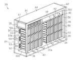
- the battery pack 30 includes a case 31.
- the case 31 includes a counterweight 32 for balancing the load 22 mounted on the fork 20.
- the counterweight 32 is erected in a thickness direction of the weight portion 34 from a weight portion 34 having a rectangular shape in plan view, and one end in the short direction of the weight portion 34 (that is, a first end in the short direction of the weight portion 34). That is, it includes a plate-like weight body 33 that is extended).
- the weight main body 33 extends from one longitudinal end of the weight portion 34 (first end in the longitudinal direction of the weight portion 34) to the other longitudinal end of the weight portion 34 (second end in the longitudinal direction of the weight portion 34).
- the weight portion 34 extends from the base end of the weight body 33 in the thickness direction of the weight body 33. In other words, the weight portion 34 extends in a direction different from the extending direction of the weight main body 33.
- a notch 35 is formed by notching the weight main body 33 in the thickness direction of the weight main body 33.
- the frame 36 is erected from the weight portion 34.
- the frame 36 includes a first pillar part 38 and a second pillar part 39 erected from two corners at one end in the short direction on the upper surface of the weight part 34, and a first pillar part 38 and a second pillar part 39.
- a base portion 37 connecting the upper end portions of the column portions 39. That is, the base part 37 connects the end part opposite to the end part joined to the weight part 34 of the first pillar part 38 and the second pillar part 39.
- the battery pack 30 has a main opening 30 a surrounded by the weight 34 and the frame 36 at the second end in the short direction of the weight 34. In the battery pack 30, the main opening 30a is closed by a lid member 43 having a rectangular plate shape.
- each column portion 38, 39 that is, the length in the longitudinal direction of each column portion 38, 39 is set to be the same as the shortest distance from the upper surface of the weight portion 34 to the distal end surface of the weight main body 33.
- a top plate 44 is supported on the upper surface of the frame 36 and the upper surface of the weight body 33. The top plate 44 closes an opening (not shown) between the weight body 33 and the frame 36.
- the battery pack 30 includes a weight body 33, a weight portion 34, a first column portion 38, and a top plate at one end in the longitudinal direction of the weight body 33 (that is, the first end in the longitudinal direction of the weight body 33).
- the first opening 30 b is surrounded by 44.
- the battery pack 30 has a weight main body 33, a weight portion 34, a second column portion 39, and a ceiling at the other longitudinal end of the weight main body 33 (that is, the second end in the longitudinal direction of the weight main body 33).
- a second opening 30 c surrounded by the plate 44 is provided.
- the first opening 30 b is closed by the first lid member 41
- the second opening 30 c is closed by the second lid member 42.
- a case 31 is formed by the counterweight 32, the frame 36, the top plate 44, and the lid members 41 to 43.
- the first surface (inner surface) in the thickness direction of the weight main body 33 is an installation surface 33a on which the battery module 50 is installed.
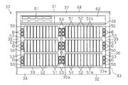
- a plurality of battery modules 50 are provided at intervals on the installation surface 33a.
- the battery modules 50 are provided in two rows at intervals in the longitudinal direction of the weight main body 33 and are arranged in three rows at intervals in the short direction of the weight main body 33.
- the battery module 50 includes a rectangular battery 51 as a battery cell such as a lithium ion secondary battery or a nickel / hydrogen storage battery, and a rectangular flat plate heat transfer plate 52 that is thermally coupled to the square battery 51. And are arranged in parallel alternately. Accordingly, the battery modules 50 are provided side by side in the width direction of the weight body 33, so that the square batteries 51 are stacked in the width direction of the weight body 33.
- the square battery 51 is provided in a stacked state in the vertical direction (vertical direction) of the vehicle body 12.
- the lateral direction of the weight main body 33 extends in the same direction as the stacking direction of the square batteries 51.
- the heat transfer plate 52 is provided adjacent to the square battery 51. The entire surface of the heat transfer plate 52 in the thickness direction is in contact with the surface of the rectangular battery 51 in the thickness direction.
- brackets 53 are fixed to the square batteries 51 located at both ends of the square batteries 51 in the juxtaposition direction. Then, the battery module 50 is fixed to the weight main body 33 by screwing the bolt B into the weight main body 33 via the bracket 53.
- the first surface 51 a in the width direction of the prismatic battery 51 and the first surface in the width direction of the heat transfer plate 52 are joined to the counterweight 32.
- the first surface 51 a in the width direction of the prismatic battery 51 is a surface orthogonal to the thickness direction and the height direction of the prismatic battery 51.
- the first surface in the width direction of the heat transfer plate 52 is a surface orthogonal to the thickness direction and the height direction of the heat transfer plate 52.
- the first surface 51a in the width direction of the square battery 51 corresponds to a joint portion with the counterweight 32 in the battery cell.
- the installation surface 33a of the weight main body 33 to which the first surface 51a in the width direction of the square battery 51 is joined corresponds to a joint portion of the counterweight 32 with the battery cell.
- the second surface (outer surface) in the thickness direction of the weight main body 33 which is the surface opposite to the installation surface 33a corresponds to a portion of the counterweight 32 opposite to the joint portion with the battery cell.
- the 2nd surface of the thickness direction of the weight main body 33 becomes the thermal radiation surface 33b heat-exchanged with driving
- the counterweight 32 is disposed in front of the vehicle body 12 and has a heat radiating surface 33b that is exposed to the outside of the vehicle body 12 and directly exchanges heat with the traveling wind.
- the heat radiating surface 33b corresponds to a portion of the counterweight 32 that is opposite to the joint portion with the battery cell.
- the counterweight 32 is formed of a metal material such as iron, for example.
- a metal material such as iron, for example.
- a mounting plate 40 having a rectangular flat plate shape is fixed to the upper surface of the notch 35.
- a housing case 61 for housing a control device for controlling the battery module 50 and a junction box 62 for housing a relay and wiring are disposed.
- the battery pack 30 configured as described above is accommodated in an accommodation space S formed in front of the vehicle body 12.
- the battery pack 30 is disposed such that the heat radiating surface 33 b opposite to the installation surface 33 a of the weight body 33 faces the front of the vehicle body 12.
- the heat radiating surface 33 b is located outside the square battery 51. The entire surface of the heat radiating surface 33 b is exposed to the outside of the vehicle body 12.
- the battery pack 30 is disposed so that the weight portion 34 is positioned below (vertically in the vertical direction) the plurality of battery modules 50.
- the heat radiating surface 33b of the weight body 33 is cooled by exchanging heat with the traveling wind.
- the heat radiating surface 33b is more than the non-joining portion with the weight main body 33 in the square battery 51. It is easy to exchange heat with running wind.
- the non-joining portion of the square battery 51 with the weight main body 33 is, for example, a surface opposite to the joint portion of the square battery 51 with the weight main body 33 (the first surface 51a in the width direction of the square battery 51).
- a second surface 51b in the width direction of the prismatic battery 51 is included.
- the heat radiating surface 33b is directly heat-exchanged with the traveling wind.
- the battery pack 30 is disposed on the vehicle body 12 so that the heat radiating surface 33b of the counterweight 32 is more easily exchanged with traveling wind than the non-joined portion of the counterweight 32 with the weight body 33 in the square battery 51. Has been. For this reason, the heat radiating surface 33b can be efficiently cooled by the traveling wind, and the counterweight 32 is not easily overheated. Therefore, the counterweight 32 can easily absorb the heat generated by the prismatic battery 51 and can cool the prismatic battery 51 efficiently.
- the weight body 33 has a short side direction extending in the same direction as the stacking direction of the square batteries 51. Since the weight body 33 extends in the same direction as the stacking direction, the assembling property of the battery module 50 is improved.
- the battery pack 30 is disposed on the vehicle body 12 such that the heat radiating surface 33b faces the front of the vehicle body 12. By directing the heat radiating surface 33b to the front of the vehicle body 12 that is susceptible to traveling wind, the heat radiating surface 33b of the weight body 33 is more easily exchanged with the traveling wind, and the counterweight 32 can be cooled more efficiently.
- the counterweight 32 has a weight portion 34 extended from the weight body 33. For this reason, compared with the case where the counter weight 32 consists only of the weight main body 33, the heat radiation area of the counter weight 32 is increased, and the counter weight 32 is further suppressed from being overheated. Therefore, the counterweight 32 can easily absorb the heat generated by the square battery 51, and the square battery 51 can be efficiently cooled.
- the battery pack 30 is disposed such that the weight portion 34 is positioned below the plurality of battery modules 50 in the vertical direction. For this reason, the position of the center of gravity of the vehicle body 12 is lowered, and the allowable weight of the load 22 that can be mounted on the fork 20 is increased.
- the weight main body 33 is provided in front of the vehicle body 12 with respect to the square battery 51. For this reason, when an impact is applied from the front of the vehicle body 12, the impact is absorbed by the weight body 33, and the square battery 51 can be protected.
- the weight main body 33 and the square battery 51 are directly bonded to each other, but the present invention is not limited to this, and may be indirectly bonded via a thermoelectric sheet. Moreover, when the square battery 51 is held by the battery holder, it may be joined via the battery holder.
- the heat radiating surface 33b of the weight main body 33 may not be directly exchanged with the traveling wind.
- a portion in front of the heat radiating surface 33b may be covered with a part of the vehicle body 12, and the vehicle body 12 and the heat radiating surface 33b of the weight main body 33 may be joined to each other.
- the traveling wind and a part of the vehicle body 12 exchange heat, and the heat radiation surface 33b is indirectly cooled through a part of the cooled vehicle body 12.
- a space may be provided between a part of the vehicle body 12 positioned in front of the heat radiating surface 33 b and the heat radiating surface 33 b of the weight main body 33.
- a part of the vehicle body 12 is cooled by heat exchange between the traveling wind and a part of the vehicle body 12.
- a part of the cooled vehicle body 12 and a heat medium (air) existing between a part of the vehicle body 12 and the heat radiating surface 33b of the weight body 33 perform heat exchange, whereby the heat medium is cooled.
- the heat radiating surface 33b is cooled by heat exchange between the cooled heat medium and the heat radiating surface 33b.
- a part of the heat radiating surface 33b may be exposed to the outside of the vehicle body 12, and only a part thereof may be directly heat exchanged with the traveling wind.
- the storage space S may be formed behind the vehicle body 12 and the battery pack 30 may be disposed behind the vehicle body 12.
- the heat radiating surface 33b faces the rear of the vehicle body 12 so that the heat radiating surface 33b is cooled by the traveling wind rather than the non-joined portion of the prismatic battery 51 with the weight main body 33.
- the battery pack 30 is disposed on the vehicle body 12.
- the counter weight 32 may be configured by only the weight main body 33 without providing the weight portion 34.
- the shape of the weight part 34 may be any shape.
- the shape of the weight main body 33 may be any shape. Even in this case, the battery is such that the joint portion of the weight body 33 with the square battery 51 is more easily exchanged with the traveling wind than the surface of the square battery 51 opposite to the joint surface with the weight body 33. A pack 30 is disposed.
- a cylindrical battery or a laminate battery may be adopted as the battery cell.
- the heat radiating surface 33b of the weight main body 33 may be disposed so as to face the vehicle width direction (lateral direction) of the vehicle body 12. That is, the prismatic battery 51 and the counter are located at a position where the joint portion of the weight body 33 with the prismatic battery 51 is more easily exchanged with the traveling wind than the surface of the prismatic battery 51 opposite to the joint surface with the weight body 33. It is only necessary that the weight 32 can be arranged.
- the industrial vehicle of the present invention may be embodied in an industrial vehicle other than the forklift 10.
- An industrial vehicle may be embodied in a power shovel, for example.
- a blower may be provided on the vehicle body 12, and the heat radiating surface 33b may be blown by the blower.
- fins may be formed on the heat radiating surface 33b to increase the heat exchange efficiency. Further, fins may be formed on the outer surface of the counterweight 32, the outer surface of the top plate 44, and the outer surfaces of the lid members 41 to 43.
- the fin may have any shape.
- the fin may be, for example, a plate-shaped fin (straight fin) or a pin-shaped fin.
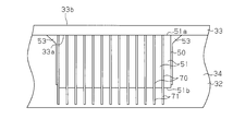
- the size of the heat transfer plate 70 along the width direction of the square battery 51 is made larger than the size of the square battery 51 in the width direction so that the heat transfer plate 70 is You may make it protrude with respect to the 2nd surface 51b of the width direction of 51.
- a part of the heat transfer plate 70 may protrude on the opposite side to the joint portion (the first surface 51 a in the width direction of the square battery 51) of the square battery 51 with the weight main body 33.
- the protruding portion 71 of the heat transfer plate 70 protruding from the second surface 51b in the width direction of the prismatic battery 51 is heat-exchanged with the surrounding heat medium, and the heat generated by the prismatic battery 51 is generated.
- the square battery 51 can be efficiently cooled. Moreover, the temperature difference in the prismatic battery 51 is reduced by cooling the weight main body 33 and the protrusion 71 of the heat transfer plate 70 from both sides in the width direction of the prismatic battery 51.
Landscapes
- Engineering & Computer Science (AREA)
- Transportation (AREA)
- Chemical & Material Sciences (AREA)
- Structural Engineering (AREA)
- Mechanical Engineering (AREA)
- Chemical Kinetics & Catalysis (AREA)
- Electrochemistry (AREA)
- General Chemical & Material Sciences (AREA)
- Life Sciences & Earth Sciences (AREA)
- Manufacturing & Machinery (AREA)
- Geology (AREA)
- Civil Engineering (AREA)
- Sustainable Development (AREA)
- Sustainable Energy (AREA)
- Power Engineering (AREA)
- Combustion & Propulsion (AREA)
- Aviation & Aerospace Engineering (AREA)
- Forklifts And Lifting Vehicles (AREA)
- Arrangement Or Mounting Of Propulsion Units For Vehicles (AREA)
- Cooling, Air Intake And Gas Exhaust, And Fuel Tank Arrangements In Propulsion Units (AREA)
Description
Claims (6)
- 産業車両であって、
車体と、
前記車体に搭載された電池パックとを備え、
前記電池パックは、カウンタウェイトと、該カウンタウェイトに一部分が接合された少なくとも一つの電池セルとを有し、
前記電池パックは、前記カウンタウェイトにおける前記電池セルとの接合部分が、前記電池セルにおける前記カウンタウェイトとの非接合部分よりも走行風と熱交換されるように前記車体に配設される、産業車両。 - 前記電池セルは、複数設けられ、前記複数の電池セルは、前記車体の上下方向に積層された状態で前記カウンタウェイトに接合される、請求項1に記載の産業車両。
- 前記電池パックは、前記カウンタウェイトにおける前記電池セルとの接合部分と反対側の少なくとも一部が前記車体の前方を向くように配設される、請求項1又は請求項2に記載の産業車両。
- 前記電池パックは、前記カウンタウェイトにおける前記電池セルとの接合部分と反対側の少なくとも一部が前記走行風と直接熱交換されるように配設される、請求項1~請求項3のうちいずれか一項に記載の産業車両。
- 前記カウンタウェイトは、前記電池セルが接合されるとともに一方向に延設されたウェイト本体と、該ウェイト本体に設けられるウェイト部とを含み、
前記ウェイト部は、前記ウェイト本体の延設方向とは異なる方向に延設される、請求項1~請求項4のうちいずれか一項に記載の産業車両。 - 前記カウンタウェイトは、前記車体の前方に配置されるとともに、前記車体の外側に露出して前記走行風と直接熱交換される放熱面を有する、請求項1~請求項5のうちいずれか一項に記載の産業車両。
Priority Applications (3)
| Application Number | Priority Date | Filing Date | Title |
|---|---|---|---|
| US14/426,839 US9481556B2 (en) | 2012-09-18 | 2013-09-03 | Industrial vehicle |
| DE112013004541.9T DE112013004541T5 (de) | 2012-09-18 | 2013-09-03 | Industriefahrzeug |
| CN201380048032.2A CN104619536B (zh) | 2012-09-18 | 2013-09-03 | 工业车辆 |
Applications Claiming Priority (2)
| Application Number | Priority Date | Filing Date | Title |
|---|---|---|---|
| JP2012-204585 | 2012-09-18 | ||
| JP2012204585A JP5692539B2 (ja) | 2012-09-18 | 2012-09-18 | 産業車両 |
Publications (1)
| Publication Number | Publication Date |
|---|---|
| WO2014045864A1 true WO2014045864A1 (ja) | 2014-03-27 |
Family
ID=50341182
Family Applications (1)
| Application Number | Title | Priority Date | Filing Date |
|---|---|---|---|
| PCT/JP2013/073654 Ceased WO2014045864A1 (ja) | 2012-09-18 | 2013-09-03 | 産業車両 |
Country Status (5)
| Country | Link |
|---|---|
| US (1) | US9481556B2 (ja) |
| JP (1) | JP5692539B2 (ja) |
| CN (1) | CN104619536B (ja) |
| DE (1) | DE112013004541T5 (ja) |
| WO (1) | WO2014045864A1 (ja) |
Families Citing this family (14)
| Publication number | Priority date | Publication date | Assignee | Title |
|---|---|---|---|---|
| JP5621859B2 (ja) * | 2013-01-25 | 2014-11-12 | 株式会社豊田自動織機 | 電池モジュール |
| BR102013033526B1 (pt) * | 2013-12-26 | 2021-07-27 | Dynapac Do Brasil Indústria E Comércio De Máquinas Ltda. | Sistema de regulação de peso de uma máquina |
| JP6267093B2 (ja) * | 2014-10-15 | 2018-01-24 | トヨタ自動車株式会社 | 車載用電源装置 |
| JP6497104B2 (ja) * | 2015-02-12 | 2019-04-10 | 株式会社豊田自動織機 | 産業車両 |
| AU2017201690B2 (en) * | 2016-03-14 | 2022-09-15 | The Raymond Corporation | Battery counterweight system |
| DE202017105488U1 (de) * | 2017-07-18 | 2018-10-24 | Mahle International Gmbh | Batteriezellenanordnung |
| DE102018000135A1 (de) * | 2018-01-10 | 2019-07-11 | Voltabox Ag | Energieversorgungseinheit für Luftfahrtbodengeräte und Flurförderzeuge |
| US11427450B2 (en) | 2018-06-01 | 2022-08-30 | Hyster-Yale Group, Inc. | Lift truck having advantageous design elements |
| DE102018216986A1 (de) * | 2018-10-04 | 2020-04-09 | Ford Global Technologies, Llc | Batterieanordnung |
| CN109850816B (zh) * | 2019-04-01 | 2020-06-16 | 湖州师范学院 | 一种具有自动散热功能的叉车 |
| US11233291B2 (en) * | 2019-04-03 | 2022-01-25 | The Raymond Corporation | Systems and methods for a modular battery system |
| US11205819B2 (en) * | 2019-04-04 | 2021-12-21 | The Raymond Corporation | Systems and methods for a battery panel assembly on a material handling vehicle |
| JP7338480B2 (ja) | 2020-01-10 | 2023-09-05 | トヨタ自動車株式会社 | 車両における電池冷却構造 |
| JP7181512B1 (ja) * | 2021-06-29 | 2022-12-01 | 株式会社テクノスヤシマ | 電池装置およびフォークリフト |
Citations (5)
| Publication number | Priority date | Publication date | Assignee | Title |
|---|---|---|---|---|
| JPH055681U (ja) * | 1991-07-05 | 1993-01-26 | 小松フオークリフト株式会社 | コントローラ取付構造 |
| JPH07133096A (ja) * | 1993-11-09 | 1995-05-23 | Nissan Motor Co Ltd | バッテリ車のコントローラ取付け構造 |
| JPH07172800A (ja) * | 1993-12-21 | 1995-07-11 | Komatsu Forklift Co Ltd | バッテリーフォークリフトトラックにおけるコントローラ取り付け構造 |
| JP2004292063A (ja) * | 2003-03-25 | 2004-10-21 | Toyota Industries Corp | 産業車両におけるコントローラ取付構造 |
| WO2011089934A1 (ja) * | 2010-01-19 | 2011-07-28 | 日立建機株式会社 | 建設機械の冷却構造 |
Family Cites Families (35)
| Publication number | Priority date | Publication date | Assignee | Title |
|---|---|---|---|---|
| US4047750A (en) * | 1976-07-19 | 1977-09-13 | Towmotor Corporation | Overhead guard-battery ballast |
| JPH055681A (ja) | 1991-06-27 | 1993-01-14 | Kawasaki Steel Corp | 薄板試験片の製作方法 |
| US5983612A (en) * | 1996-11-01 | 1999-11-16 | Textron, Inc. | Removable battery tray system for an electrically powered bunker rake |
| GB2331054B (en) * | 1997-11-06 | 2001-08-08 | Lansing Linde Ltd | Industrial truck with a battery block |
| JP2002020085A (ja) * | 2000-07-05 | 2002-01-23 | Toyota Industries Corp | フォークリフトのフード開閉装置 |
| JP3759049B2 (ja) * | 2002-02-06 | 2006-03-22 | 小松フォークリフト株式会社 | 産業車両のコントローラ放熱構造 |
| JP4196375B2 (ja) * | 2003-02-04 | 2008-12-17 | 株式会社小松製作所 | カウンタウエイト |
| US7651811B2 (en) * | 2004-01-28 | 2010-01-26 | Aker Wade Power Technologies, Llc | Thermal management of fast charging high capacity batteries |
| JP4062273B2 (ja) * | 2004-03-31 | 2008-03-19 | 日産自動車株式会社 | 組電池 |
| KR20060027578A (ko) * | 2004-09-23 | 2006-03-28 | 삼성에스디아이 주식회사 | 이차 전지 모듈 온도 제어 시스템 |
| JP4544121B2 (ja) * | 2005-09-29 | 2010-09-15 | コベルコ建機株式会社 | 建設機械 |
| KR100728840B1 (ko) * | 2005-12-27 | 2007-06-19 | 두산인프라코어 주식회사 | 지게차의 배터리 지지구조 |
| US8100210B2 (en) * | 2006-02-07 | 2012-01-24 | Takeuchi Mfg. Co., Ltd | Electrically driven industrial vehicle |
| DE102006030770A1 (de) * | 2006-06-30 | 2008-01-24 | Jungheinrich Ag | Batterieblock für ein Flurförderzeug |
| DE102007045435A1 (de) * | 2007-09-22 | 2009-04-02 | Jungheinrich Aktiengesellschaft | Batteriebetriebenes Flurförderzeug |
| KR20090006067U (ko) * | 2007-12-14 | 2009-06-18 | 현대중공업 주식회사 | 배터리 수납을 병행하는 전동식 산업차량의 카운터웨이트 |
| JP2009274651A (ja) | 2008-05-16 | 2009-11-26 | Toyota Industries Corp | ハイブリッド産業車両 |
| US20100122860A1 (en) * | 2008-11-18 | 2010-05-20 | Mckelvey Albert T | Electric off-road vehicle drive |
| JP4905446B2 (ja) * | 2008-12-24 | 2012-03-28 | 株式会社豊田自動織機 | 産業車両 |
| JP4867998B2 (ja) * | 2009-01-16 | 2012-02-01 | 株式会社豊田自動織機 | 産業車両用電気部品ユニットおよび該ユニットを有する産業車両 |
| US20130171480A1 (en) * | 2010-06-03 | 2013-07-04 | A123 Systems, Inc. | System and Method for Monitoring Battery Bus Bars Within a Battery Pack |
| JP5172898B2 (ja) * | 2010-06-15 | 2013-03-27 | 日立建機株式会社 | 電動式建設機械 |
| US8857635B2 (en) * | 2010-12-22 | 2014-10-14 | Terex Cranes Germany Gmbh | Crane and method for operating a crane using recovery of energy from crane operations as a secondary energy source |
| JP5814577B2 (ja) * | 2011-03-24 | 2015-11-17 | 株式会社小松製作所 | 電動式作業車両及びそのバッテリ保持構造 |
| JP5814578B2 (ja) * | 2011-03-24 | 2015-11-17 | 株式会社小松製作所 | 電動式作業車両及びそのベースフレーム |
| DE112012000063T5 (de) * | 2011-04-08 | 2013-08-22 | Komatsu Ltd. | Batterieangetriebener Gabelstapler |
| JP5513445B2 (ja) * | 2011-06-08 | 2014-06-04 | 本田技研工業株式会社 | 車両用電源装置 |
| US8968906B2 (en) * | 2011-09-20 | 2015-03-03 | GM Global Technology Operations LLC | Compact battery cooling design |
| US8945749B2 (en) * | 2011-12-15 | 2015-02-03 | GM Global Technology Operations LLC | Carbon fiber thermal interface for cooling module assembly |
| US20150139768A1 (en) * | 2012-06-04 | 2015-05-21 | Hitachi Construction Machinery Co., Ltd. | Construction machine |
| JP5590080B2 (ja) * | 2012-08-13 | 2014-09-17 | 株式会社豊田自動織機 | 産業車両 |
| JP5837863B2 (ja) * | 2012-08-21 | 2015-12-24 | 日立建機株式会社 | 電動式建設機械 |
| JP5751634B2 (ja) * | 2012-09-28 | 2015-07-22 | 株式会社Gsユアサ | 蓄電装置 |
| CN104508901B (zh) * | 2013-08-02 | 2017-04-05 | 株式会社小松制作所 | 作业车辆用电池以及电池式作业车辆 |
| JP5676784B1 (ja) * | 2013-08-02 | 2015-02-25 | 株式会社小松製作所 | 作業車両用バッテリ及びバッテリ式作業車両 |
-
2012
- 2012-09-18 JP JP2012204585A patent/JP5692539B2/ja active Active
-
2013
- 2013-09-03 WO PCT/JP2013/073654 patent/WO2014045864A1/ja not_active Ceased
- 2013-09-03 DE DE112013004541.9T patent/DE112013004541T5/de not_active Ceased
- 2013-09-03 CN CN201380048032.2A patent/CN104619536B/zh not_active Expired - Fee Related
- 2013-09-03 US US14/426,839 patent/US9481556B2/en not_active Expired - Fee Related
Patent Citations (5)
| Publication number | Priority date | Publication date | Assignee | Title |
|---|---|---|---|---|
| JPH055681U (ja) * | 1991-07-05 | 1993-01-26 | 小松フオークリフト株式会社 | コントローラ取付構造 |
| JPH07133096A (ja) * | 1993-11-09 | 1995-05-23 | Nissan Motor Co Ltd | バッテリ車のコントローラ取付け構造 |
| JPH07172800A (ja) * | 1993-12-21 | 1995-07-11 | Komatsu Forklift Co Ltd | バッテリーフォークリフトトラックにおけるコントローラ取り付け構造 |
| JP2004292063A (ja) * | 2003-03-25 | 2004-10-21 | Toyota Industries Corp | 産業車両におけるコントローラ取付構造 |
| WO2011089934A1 (ja) * | 2010-01-19 | 2011-07-28 | 日立建機株式会社 | 建設機械の冷却構造 |
Also Published As
| Publication number | Publication date |
|---|---|
| US20150239719A1 (en) | 2015-08-27 |
| CN104619536B (zh) | 2017-04-05 |
| US9481556B2 (en) | 2016-11-01 |
| DE112013004541T5 (de) | 2015-05-28 |
| CN104619536A (zh) | 2015-05-13 |
| JP2014058242A (ja) | 2014-04-03 |
| JP5692539B2 (ja) | 2015-04-01 |
Similar Documents
| Publication | Publication Date | Title |
|---|---|---|
| JP5692539B2 (ja) | 産業車両 | |
| JP5590080B2 (ja) | 産業車両 | |
| JP5904113B2 (ja) | 電池モジュール及び電池モジュールの製造方法 | |
| JP6497314B2 (ja) | 電池パック | |
| JP6127524B2 (ja) | 電池パック | |
| JP6123299B2 (ja) | 電池パック及び産業車両 | |
| JP5621859B2 (ja) | 電池モジュール | |
| JP5660103B2 (ja) | 産業車両 | |
| JP5692540B2 (ja) | 産業車両 | |
| JP5949422B2 (ja) | 産業車両 | |
| JP5974721B2 (ja) | 電池パック | |
| JP5482864B1 (ja) | 電池モジュール | |
| JP2014146461A (ja) | 電池パック | |
| JP5978983B2 (ja) | 電池モジュール | |
| JP2014110218A (ja) | 電池モジュール | |
| JP6304426B2 (ja) | 電池パック | |
| JP5978974B2 (ja) | 電池パック | |
| JP6060694B2 (ja) | 電池モジュール |
Legal Events
| Date | Code | Title | Description |
|---|---|---|---|
| 121 | Ep: the epo has been informed by wipo that ep was designated in this application |
Ref document number: 13839681 Country of ref document: EP Kind code of ref document: A1 |
|
| WWE | Wipo information: entry into national phase |
Ref document number: 14426839 Country of ref document: US |
|
| WWE | Wipo information: entry into national phase |
Ref document number: 1120130045419 Country of ref document: DE Ref document number: 112013004541 Country of ref document: DE |
|
| 122 | Ep: pct application non-entry in european phase |
Ref document number: 13839681 Country of ref document: EP Kind code of ref document: A1 |