WO2014041876A1 - 荷電粒子線装置及び試料観察方法 - Google Patents
荷電粒子線装置及び試料観察方法 Download PDFInfo
- Publication number
- WO2014041876A1 WO2014041876A1 PCT/JP2013/068201 JP2013068201W WO2014041876A1 WO 2014041876 A1 WO2014041876 A1 WO 2014041876A1 JP 2013068201 W JP2013068201 W JP 2013068201W WO 2014041876 A1 WO2014041876 A1 WO 2014041876A1
- Authority
- WO
- WIPO (PCT)
- Prior art keywords
- sample
- charged particle
- diaphragm
- particle beam
- housing
- Prior art date
Links
- 239000002245 particle Substances 0.000 title claims abstract description 145
- 238000000034 method Methods 0.000 title claims abstract description 13
- 230000003287 optical effect Effects 0.000 claims abstract description 51
- 230000002265 prevention Effects 0.000 claims abstract description 40
- 230000007246 mechanism Effects 0.000 claims abstract description 12
- 238000001514 detection method Methods 0.000 claims description 9
- 238000013459 approach Methods 0.000 claims description 4
- 230000001678 irradiating effect Effects 0.000 claims 3
- 238000007796 conventional method Methods 0.000 abstract 1
- 239000000523 sample Substances 0.000 description 164
- 239000007789 gas Substances 0.000 description 58
- 230000006870 function Effects 0.000 description 14
- 238000007789 sealing Methods 0.000 description 13
- 238000010894 electron beam technology Methods 0.000 description 9
- 238000010586 diagram Methods 0.000 description 8
- 238000004891 communication Methods 0.000 description 5
- 230000000694 effects Effects 0.000 description 5
- IJGRMHOSHXDMSA-UHFFFAOYSA-N Atomic nitrogen Chemical compound N#N IJGRMHOSHXDMSA-UHFFFAOYSA-N 0.000 description 4
- 230000007613 environmental effect Effects 0.000 description 4
- 238000009434 installation Methods 0.000 description 4
- 239000007788 liquid Substances 0.000 description 4
- 238000012545 processing Methods 0.000 description 4
- 230000005540 biological transmission Effects 0.000 description 3
- 230000006872 improvement Effects 0.000 description 3
- 150000002500 ions Chemical class 0.000 description 3
- 239000000463 material Substances 0.000 description 3
- 230000013011 mating Effects 0.000 description 3
- 238000012986 modification Methods 0.000 description 3
- 230000004048 modification Effects 0.000 description 3
- 239000004065 semiconductor Substances 0.000 description 3
- 230000008859 change Effects 0.000 description 2
- 238000006073 displacement reaction Methods 0.000 description 2
- 229910052757 nitrogen Inorganic materials 0.000 description 2
- 229910052710 silicon Inorganic materials 0.000 description 2
- 239000010703 silicon Substances 0.000 description 2
- YCKRFDGAMUMZLT-UHFFFAOYSA-N Fluorine atom Chemical compound [F] YCKRFDGAMUMZLT-UHFFFAOYSA-N 0.000 description 1
- UFHFLCQGNIYNRP-UHFFFAOYSA-N Hydrogen Chemical compound [H][H] UFHFLCQGNIYNRP-UHFFFAOYSA-N 0.000 description 1
- 229910052581 Si3N4 Inorganic materials 0.000 description 1
- VYPSYNLAJGMNEJ-UHFFFAOYSA-N Silicium dioxide Chemical compound O=[Si]=O VYPSYNLAJGMNEJ-UHFFFAOYSA-N 0.000 description 1
- 239000000853 adhesive Substances 0.000 description 1
- 230000001070 adhesive effect Effects 0.000 description 1
- 230000032683 aging Effects 0.000 description 1
- 230000003321 amplification Effects 0.000 description 1
- 238000004458 analytical method Methods 0.000 description 1
- QVGXLLKOCUKJST-UHFFFAOYSA-N atomic oxygen Chemical compound [O] QVGXLLKOCUKJST-UHFFFAOYSA-N 0.000 description 1
- 239000012472 biological sample Substances 0.000 description 1
- 239000003575 carbonaceous material Substances 0.000 description 1
- 230000007423 decrease Effects 0.000 description 1
- 238000009429 electrical wiring Methods 0.000 description 1
- 238000002149 energy-dispersive X-ray emission spectroscopy Methods 0.000 description 1
- 230000008020 evaporation Effects 0.000 description 1
- 238000001704 evaporation Methods 0.000 description 1
- 229910052731 fluorine Inorganic materials 0.000 description 1
- 239000011737 fluorine Substances 0.000 description 1
- 239000011521 glass Substances 0.000 description 1
- 239000001307 helium Substances 0.000 description 1
- 229910052734 helium Inorganic materials 0.000 description 1
- SWQJXJOGLNCZEY-UHFFFAOYSA-N helium atom Chemical compound [He] SWQJXJOGLNCZEY-UHFFFAOYSA-N 0.000 description 1
- 238000007689 inspection Methods 0.000 description 1
- 238000012423 maintenance Methods 0.000 description 1
- 238000004519 manufacturing process Methods 0.000 description 1
- 238000005259 measurement Methods 0.000 description 1
- 239000012528 membrane Substances 0.000 description 1
- 238000003199 nucleic acid amplification method Methods 0.000 description 1
- 239000011368 organic material Substances 0.000 description 1
- 239000001301 oxygen Substances 0.000 description 1
- 229910052760 oxygen Inorganic materials 0.000 description 1
- -1 polytetrafluoroethylene Polymers 0.000 description 1
- 229920001343 polytetrafluoroethylene Polymers 0.000 description 1
- 239000004810 polytetrafluoroethylene Substances 0.000 description 1
- 238000002360 preparation method Methods 0.000 description 1
- 238000007634 remodeling Methods 0.000 description 1
- 239000011347 resin Substances 0.000 description 1
- 229920005989 resin Polymers 0.000 description 1
- HBMJWWWQQXIZIP-UHFFFAOYSA-N silicon carbide Chemical compound [Si+]#[C-] HBMJWWWQQXIZIP-UHFFFAOYSA-N 0.000 description 1
- 229910010271 silicon carbide Inorganic materials 0.000 description 1
- HQVNEWCFYHHQES-UHFFFAOYSA-N silicon nitride Chemical compound N12[Si]34N5[Si]62N3[Si]51N64 HQVNEWCFYHHQES-UHFFFAOYSA-N 0.000 description 1
- 229910052814 silicon oxide Inorganic materials 0.000 description 1
- 239000007787 solid Substances 0.000 description 1
- 238000003860 storage Methods 0.000 description 1
- 239000000126 substance Substances 0.000 description 1
- 239000010409 thin film Substances 0.000 description 1
- XLYOFNOQVPJJNP-UHFFFAOYSA-N water Substances O XLYOFNOQVPJJNP-UHFFFAOYSA-N 0.000 description 1
- 238000001039 wet etching Methods 0.000 description 1
Images


Classifications
-
- H—ELECTRICITY
- H01—ELECTRIC ELEMENTS
- H01J—ELECTRIC DISCHARGE TUBES OR DISCHARGE LAMPS
- H01J37/00—Discharge tubes with provision for introducing objects or material to be exposed to the discharge, e.g. for the purpose of examination or processing thereof
- H01J37/02—Details
- H01J37/18—Vacuum locks ; Means for obtaining or maintaining the desired pressure within the vessel
-
- H—ELECTRICITY
- H01—ELECTRIC ELEMENTS
- H01J—ELECTRIC DISCHARGE TUBES OR DISCHARGE LAMPS
- H01J37/00—Discharge tubes with provision for introducing objects or material to be exposed to the discharge, e.g. for the purpose of examination or processing thereof
- H01J37/02—Details
- H01J37/20—Means for supporting or positioning the object or the material; Means for adjusting diaphragms or lenses associated with the support
-
- H—ELECTRICITY
- H01—ELECTRIC ELEMENTS
- H01J—ELECTRIC DISCHARGE TUBES OR DISCHARGE LAMPS
- H01J2237/00—Discharge tubes exposing object to beam, e.g. for analysis treatment, etching, imaging
- H01J2237/16—Vessels
-
- H—ELECTRICITY
- H01—ELECTRIC ELEMENTS
- H01J—ELECTRIC DISCHARGE TUBES OR DISCHARGE LAMPS
- H01J2237/00—Discharge tubes exposing object to beam, e.g. for analysis treatment, etching, imaging
- H01J2237/18—Vacuum control means
- H01J2237/182—Obtaining or maintaining desired pressure
- H01J2237/1825—Evacuating means
-
- H—ELECTRICITY
- H01—ELECTRIC ELEMENTS
- H01J—ELECTRIC DISCHARGE TUBES OR DISCHARGE LAMPS
- H01J2237/00—Discharge tubes exposing object to beam, e.g. for analysis treatment, etching, imaging
- H01J2237/20—Positioning, supporting, modifying or maintaining the physical state of objects being observed or treated
- H01J2237/2002—Controlling environment of sample
- H01J2237/2003—Environmental cells
-
- H—ELECTRICITY
- H01—ELECTRIC ELEMENTS
- H01J—ELECTRIC DISCHARGE TUBES OR DISCHARGE LAMPS
- H01J2237/00—Discharge tubes exposing object to beam, e.g. for analysis treatment, etching, imaging
- H01J2237/20—Positioning, supporting, modifying or maintaining the physical state of objects being observed or treated
- H01J2237/202—Movement
- H01J2237/20221—Translation
- H01J2237/20235—Z movement or adjustment
-
- H—ELECTRICITY
- H01—ELECTRIC ELEMENTS
- H01J—ELECTRIC DISCHARGE TUBES OR DISCHARGE LAMPS
- H01J2237/00—Discharge tubes exposing object to beam, e.g. for analysis treatment, etching, imaging
- H01J2237/20—Positioning, supporting, modifying or maintaining the physical state of objects being observed or treated
- H01J2237/202—Movement
- H01J2237/20292—Means for position and/or orientation registration
-
- H—ELECTRICITY
- H01—ELECTRIC ELEMENTS
- H01J—ELECTRIC DISCHARGE TUBES OR DISCHARGE LAMPS
- H01J2237/00—Discharge tubes exposing object to beam, e.g. for analysis treatment, etching, imaging
- H01J2237/26—Electron or ion microscopes
- H01J2237/2602—Details
- H01J2237/2605—Details operating at elevated pressures, e.g. atmosphere
- H01J2237/2608—Details operating at elevated pressures, e.g. atmosphere with environmental specimen chamber
-
- H—ELECTRICITY
- H01—ELECTRIC ELEMENTS
- H01J—ELECTRIC DISCHARGE TUBES OR DISCHARGE LAMPS
- H01J37/00—Discharge tubes with provision for introducing objects or material to be exposed to the discharge, e.g. for the purpose of examination or processing thereof
- H01J37/26—Electron or ion microscopes; Electron or ion diffraction tubes
- H01J37/261—Details
-
- H—ELECTRICITY
- H01—ELECTRIC ELEMENTS
- H01J—ELECTRIC DISCHARGE TUBES OR DISCHARGE LAMPS
- H01J37/00—Discharge tubes with provision for introducing objects or material to be exposed to the discharge, e.g. for the purpose of examination or processing thereof
- H01J37/26—Electron or ion microscopes; Electron or ion diffraction tubes
- H01J37/28—Electron or ion microscopes; Electron or ion diffraction tubes with scanning beams
Definitions
- the present invention relates to a charged particle beam device capable of observing a sample at atmospheric pressure or under a predetermined pressure.
- a scanning electron microscope (SEM), a transmission electron microscope (TEM), or the like is used to observe a minute region of the object.
- SEM scanning electron microscope
- TEM transmission electron microscope
- a housing for placing a sample is evacuated, and a sample atmosphere is vacuumed to image the sample.
- biochemical samples, liquid samples and the like are damaged or changed in state by vacuum.
- an SEM apparatus and a sample holding apparatus capable of observing a sample to be observed under atmospheric pressure have been developed.
- These devices in principle, provide a diaphragm or a fine through-hole through which an electron beam can pass between the electron optical system and the sample to separate the vacuum state and the atmospheric state, and both of the sample and the electron optical system It is common in providing a diaphragm between
- the electron source side of the electron optical lens barrel is oriented downward and the objective lens side is oriented upward, and an electron beam is emitted through the O ring on the electron beam emission hole at the end of the electron optical lens barrel.
- an SEM provided with a diaphragm through which
- a sample to be observed is directly mounted on a diaphragm, and a primary electron beam is irradiated from the lower surface of the sample to detect reflected electrons or secondary electrons and perform SEM observation.
- the sample is held in a space constituted by an annular member placed around the diaphragm, and the space is further filled with a liquid such as water.
- the conventional charged particle beam devices are devices specially designed for observation under atmospheric pressure or under a gas atmosphere at a pressure substantially equal to atmospheric pressure, and are widely used using a conventional high vacuum type charged particle microscope. There is no device that can easily perform observation under a gas atmosphere at a pressure substantially equal to atmospheric pressure or atmospheric pressure.
- Patent Document 1 the SEM described in Patent Document 1 is a structurally very special device, and SEM observation in a normal high vacuum atmosphere is not feasible.
- the present invention has been made in view of such problems, and it is an object of the present invention to provide a charged particle beam apparatus capable of observing a sample in the air or gas atmosphere without largely changing the configuration of a conventional high vacuum type charged particle microscope. Intended to be provided.
- the present application includes a plurality of means for solving the above problems, and one example thereof is at least a part of the contact preventing member for preventing the contact between the sample and the removable diaphragm which transmits or passes the primary charged particle beam. And an adjusting mechanism that can move the light source in the direction of the optical axis of the charged particle optical lens barrel.
- a sample can be observed in the air or gas atmosphere without significantly changing the configuration of a conventional high vacuum type charged particle microscope, and the diaphragm and the sample are not in contact with each other. It is possible to provide a charged particle beam device that can be observed.
- FIG. 5 is a configuration diagram of a charged particle microscope of Example 2.
- FIG. 5 is a configuration diagram of a charged particle microscope of Example 2.
- FIG. 5 is a configuration diagram of a charged particle microscope of Example 2.
- FIG. 5 is a configuration diagram of a charged particle microscope of Example 2.
- FIG. 5 is a configuration diagram of a charged particle microscope of Example 3.
- FIG. 5 is a configuration diagram of a charged particle microscope of Example 4.
- a charged particle beam microscope is demonstrated as an example of a charged particle beam apparatus.
- this is merely an example of the present invention, and the present invention is not limited to the embodiments described below.
- the present invention is also applicable to a scanning electron microscope, a scanning ion microscope, a scanning transmission electron microscope, a combined apparatus of these and a sample processing apparatus, or an analysis / inspection apparatus to which these are applied.
- atmospheric pressure means an atmospheric atmosphere or a predetermined gas atmosphere, and means a pressure environment of atmospheric pressure or a slight negative pressure or a pressurized state. Specifically, the pressure is about 10 5 Pa (atmospheric pressure) to about 10 3 Pa or so.
- FIG. 1 shows the entire configuration of the charged particle microscope of the present embodiment.
- the charged particle microscope shown in FIG. 1 mainly includes a charged particle optical lens barrel 2 and a first housing 7 (hereinafter sometimes referred to as a vacuum chamber) for supporting the charged particle optical lens barrel with respect to the apparatus installation surface. It is comprised by the 2nd housing
- the vacuum pump 4 When the charged particle microscope is used, the inside of the charged particle optical lens barrel 2 and the first housing 7 is evacuated by the vacuum pump 4. The start and stop operations of the vacuum pump 4 are also controlled by the control system. Although only one vacuum pump 4 is shown in the figure, there may be two or more.
- the charged particle optical column 2 includes elements such as a charged particle source 8 for generating a charged particle beam, an optical lens 1 for focusing the generated charged particle beam and guiding it to the lower part of the lens barrel and scanning the sample 6 as a primary charged particle beam. It consists of The charged particle optical lens barrel 2 is installed so as to protrude inside the first housing 7 and is fixed to the first housing 7 via the vacuum sealing member 123. At the end of the charged particle optical lens barrel 2, a detector 3 for detecting secondary charged particles (such as secondary electrons or reflected electrons) obtained by the irradiation of the primary charged particle beam is disposed.
- secondary charged particles such as secondary electrons or reflected electrons
- the charged particle microscope of the present embodiment is a vacuum exhaust system or a charge according to an instruction transmitted from a computer 35 used by an apparatus user, a host control unit 36 connected with the computer 35 and performing communication, and a host control unit 36.
- a lower control unit 37 that controls particle optics and the like is provided.
- the computer 35 includes a monitor on which an operation screen (GUI) of the apparatus is displayed, and an input unit to an operation screen such as a keyboard or a mouse.
- GUI operation screen
- the upper control unit 36, the lower control unit 37, and the computer 35 are connected by communication lines 43 and 44, respectively.
- the lower control unit 37 is a unit for transmitting and receiving control signals for controlling the vacuum pump 4, the charged particle source 8, the optical lens 1 and the like, and further converts the output signal of the detector 3 into a digital image signal to perform upper control Send to section 36.
- the output signal from the detector 3 is connected to the lower control unit 37 via an amplifier 154 such as a preamplifier. If the amplifier is not necessary, it may not be necessary.
- the upper control unit 36 and the lower control unit 37 may be mixed with analog circuits and digital circuits, and the upper control unit 36 and the lower control unit 37 may be unified into one.
- the configuration of the control system shown in FIG. 1 is merely an example, and modifications of the control unit, the valve, the vacuum pump, and the wiring for communication, etc. may be charged in the present embodiment as long as the functions intended in the present embodiment are satisfied. It belongs to the category of particle beam microscope.
- a vacuum pipe 16 whose one end is connected to the vacuum pump 4 is connected to the first housing 7 so that the inside can be maintained in a vacuum state.
- the leak valve 14 for opening the inside of the case to the atmosphere can be provided, and the inside of the first case 7 can be opened to the atmosphere at the time of maintenance or the like.
- the leak valve 14 may not be present or may be two or more.
- the position where the leak valve 14 is disposed in the first housing 7 is not limited to the position shown in FIG. 1, and may be disposed at another position on the first housing 7.
- the first housing 7 is provided with an opening on the side, and the second housing 121 is inserted through the opening.
- the second housing 121 is configured of a rectangular parallelepiped main body portion 131 and an alignment portion 132. At least one side surface of the rectangular parallelepiped side surface of the main body portion 131 is an open surface 9 as described later.
- the surfaces other than the surface on which the diaphragm holding member 155 is installed may be constituted by the wall of the second housing 121, and the second housing 121 itself has no wall. It may be configured by the side wall of the first casing 7 in a state of being incorporated into the first casing 7.
- the position of the second housing 121 is fixed to the side surface or no wall surface of the first housing 7 or the charged particle optical lens barrel.
- the main body portion 131 has a function of storing the sample 6 to be observed in a state of being inserted into the first housing 7 through the opening and being incorporated in the first housing 7.
- the mating portion 132 forms a mating surface with the outer wall surface on the side of the side where the opening of the first housing 7 is provided, and is fixed to the outer wall surface on the side of the side via the vacuum sealing member 126.
- the entire second housing 121 is fitted to the first housing 7. It is most convenient to manufacture the above-mentioned opening part using the opening for carrying in / out of the sample originally provided in the vacuum sample chamber of the charged particle microscope. That is, if the second housing 121 is manufactured according to the size of the hole that is originally opened and the vacuum sealing member 126 is attached around the hole, remodeling of the device is minimal. Also, the second housing 121 can be removed from the first housing 7.
- a diaphragm 10 is provided on the upper surface side of the second housing 121 at a position immediately below the charged particle optical lens barrel 2 when the entire second housing 121 is fitted to the first housing 7.
- the diaphragm 10 can transmit or pass the primary charged particle beam emitted from the lower end of the charged particle optical column 2, and the primary charged particle beam finally reaches the sample 6 through the diaphragm 10. Do.
- the charged particle beam that has reached the sample 6 emits secondary charged particle beams such as reflected charged particles and transmitted charged particles from inside or on the surface of the sample.
- the secondary charged particles are detected by the detector 3. Since the detector 3 is on the side of the sample surface irradiated with the charged particles, it is possible to acquire information on the sample surface.
- the detector 3 is a detection element that can detect charged particles coming in with energy of several keV to several tens of keV. Furthermore, the detection element may have a signal amplification means.
- the detection element is preferably thin and flat in view of the device configuration. For example, a semiconductor detector made of a semiconductor material such as silicon, a scintillator capable of converting a charged particle signal into light on a glass surface or inside, etc.
- the side surface of the second housing 121 is an open surface 9 communicated with the atmospheric space at least in a surface capable of taking in and out the sample, and the inside of the second housing 121 (right Afterward, the sample 6 stored in the second space is placed at atmospheric pressure during observation.
- FIG. 1 is a cross-sectional view of the apparatus parallel to the optical axis, only one open surface 9 is shown, but the vacuum sealing is performed by the side surface of the first housing in the back and front directions in FIG. If it is done, the open surface 9 of the second casing 121 is not limited to one surface. In the state in which the second housing 121 is incorporated into the first housing 7, at least one or more open surfaces may be provided.
- a vacuum pump 4 is connected to the first housing 7, and a closed space (hereinafter referred to as a first space) constituted by the inner wall surface of the first housing 7, the outer wall surface of the second housing and the diaphragm 10. Can be evacuated.
- a first space constituted by the inner wall surface of the first housing 7, the outer wall surface of the second housing and the diaphragm 10.
- the particle optical column 2 and the detector 3 can be maintained in a vacuum state, and the sample 6 can be maintained at the atmospheric pressure.
- the diaphragm 10 is deposited or deposited on the base 159.
- the diaphragm 10 is a carbon material, an organic material, silicon nitride, silicon carbide, silicon oxide or the like.
- the base 159 is a member such as silicon, for example, and a tapered hole 165 is dug as shown in the figure by processing such as wet etching, and the diaphragm 10 is provided on the lower surface in FIG.
- the diaphragm 10 may have a plurality of multi-windows.
- the thickness of the membrane capable of transmitting or passing the primary charged particle beam is about several nm to several ⁇ m.
- an aperture member provided with a primary charged particle beam passage hole may be used, and the hole diameter in that case is about 1 mm 2 or less in area from the requirement of differential evacuation with a realistic vacuum pump. Is desirable.
- the charged particle beam is an ion, it is difficult to penetrate without damaging the diaphragm, so an aperture having an area of about 1 mm 2 or less is used.
- the position of the diaphragm 10 is adjusted so that the center of the diaphragm 10 coincides with the axis of the optical axis (the alternate long and short dash line in FIG. 1) of the charged particle optical lens barrel 2.
- the diaphragm 10 and the optical axis of the charged particle optical lens barrel 2 are coaxially arranged.
- the distance between the sample 6 and the diaphragm 10 is adjusted by placing a sample table 17 of an appropriate height.
- the diaphragm 10 may be disposed at only one place.
- the area of the diaphragm 10 is several tens ⁇ m to several mm at most.
- the shape of the diaphragm 10 may not be square, but may be rectangular or the like. The shape may be any shape.
- the side shown in FIG. 2, that is, the side on which the tapered portion 165 is located is disposed on the vacuum side (the upper side in the drawing). This is to detect the secondary charged particles emitted from the sample efficiently by the detector 3.
- the second case of the present embodiment is easily enlarged because it is inserted from the side of the sample chamber, and therefore observation can be made even for a large sample that can not be enclosed in an environmental cell. Furthermore, since the second housing 121 has an open surface, the sample can be moved between the inside and the outside of the second space 12 during observation, and sample exchange can be easily performed.
- the sample 6 is disposed in a non-contact state with the diaphragm 10, and therefore, observation can be performed under high vacuum or atmospheric pressure without changing the state of the sample.
- the sample since the sample is not placed on the diaphragm, the possibility of the diaphragm being damaged by the sample can be reduced.
- the charged particle beam that has passed through the diaphragm is scattered by the atmospheric space. Under atmospheric pressure, the mean free path of charged particle beams is very short. Therefore, it is desirable that the distance between the diaphragm 10 and the sample 6 be shorter. Specifically, the thickness needs to be about 1000 ⁇ m or less. However, when the diaphragm 10 and the sample 6 are brought close to each other, if the diaphragm 10 and the sample 6 come in contact with each other by mistake, the diaphragm 10 may be broken.
- the diaphragm 10 and the sample 6 are provided with a contact preventing member for preventing the contact.
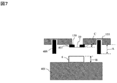
- the contact preventing member will be described with reference to FIG. In the drawings, only the periphery of the diaphragm and the periphery of the sample are illustrated for simplification of the description.
- a contact preventing member 400 is provided between the sample 6 and the diaphragm 10. The contact preventing member is provided so as to protrude from the sample stand, and as shown in FIG. 3A, the tip of the contact preventing member 400 is always disposed on the diaphragm side relative to the sample 6. Then, as shown in FIG.
- the adjustment mechanism may be any mechanism that can move the position of the contact prevention member 400 at which the sample contacts the diaphragm in the optical axis direction of the charged particle optical lens barrel.
- a vacuum sealing member 407 is illustrated for vacuum sealing between the diaphragm holding member 155 and the diaphragm 10.
- the vacuum sealing member 407 is, for example, an adhesive or a double-sided tape. If the vacuum sealing member is present between the diaphragm holding member 155 and the diaphragm 10, the thickness C of the vacuum sealing member of the diaphragm holding member 155 and the diaphragm 10 and the diaphragm 10 are integrated. It becomes a distance.
- the height using a laser or light can be measured outside the apparatus with the sample holder 401 on which the sample 6 is mounted and the diaphragm holding member 155 holding the diaphragm 10.
- the distance between A, B and C can be observed using an instrument. If the sample 6 and the diaphragm 10 always have the same height, once the distance A from the sample table 401 to the contact preventing member 400 is determined, there is no need to adjust the contact preventing member 400 again.
- the contact preventing member also has an effect that the distance from the diaphragm to the surface of the sample can be kept constant by bringing the contact preventing member into contact with the diaphragm holding member.
- the sample 6 is mounted on the sample table 401.
- the contact preventing member 400 is inserted into the female screw 402.
- the distance between the surface of the sample 6 and the upper portion of the contact prevention member 400 is a term of (AB) shown by [Expression 1] or [Expression 2].
- AB the distance between the surface of the sample 6 and the upper portion of the contact prevention member 400
- [Expression 1] or [Expression 2] the distance between the surface of the sample 6 and the upper portion of the contact prevention member 400.
- measurement or recording is performed using a laser or a device capable of measuring the height using light.
- the sample stand with the contact prevention member 400 and the sample 6 is provided on the sample stage 5 directly below the diaphragm 10.
- the contact preventing member 400 and the diaphragm holding member 155 are brought into contact with each other. Thereby, it becomes possible to irradiate the sample 6 with the charged particle beam via the diaphragm 10.
- the irradiation of the charged particle beam may be performed before the sample 6 approaches.
- FIG. 4 shows an example in which a plurality of contact preventing members 400 are provided.
- FIG. 4 (a) shows a side sectional view
- FIG. 4 (b) shows a perspective view.
- only one contact prevention member 400 is shown in FIG. 3, it may be disposed in two places as shown in FIG. 4.
- the probability that the diaphragm 10 and the sample 6 come in contact with each other when the sample stand is inclined with respect to the diaphragm, as compared with the case where only one place is arranged Can be reduced.
- the ball bearing 406 may be disposed on the contact preventing member 400.
- the ball bearing 406 comes in contact with the diaphragm holding member 155.
- the ball bearing 406 is disposed at the tip of the contact preventing member 400, it is possible to move the sample in the lateral direction or the paper surface direction in the drawing while the contact preventing member 400 is in contact with the diaphragm holding member 155.
- the sample table is held by the charged particle optical lens barrel
- the structure is not limited to the ball bearing as long as it can be driven in the direction perpendicular to the optical axis, and this member is referred to as a fine adjustment member. If the friction between the contact prevention member 400 and the diaphragm holding member 155 is small, the fine adjustment member may not be a ball bearing.
- a material having a small coefficient of friction may be used among organic substances such as fluorine resin represented by polytetrafluoroethylene, or the like, and the contact prevention member 400 and the diaphragm holding member 155 may be used by minimizing the contact area. You may improve the slip between them.
- FIG. FIG. 6 (a) shows a side sectional view
- FIG. 6 (b) shows a perspective view
- the contact prevention member 400 may be disposed on the entire outside of the sample table 401.
- the outer periphery of the sample table 401 is an external thread
- the inner side of the contact prevention member 400 is a female screw, whereby the sample table 401 is rotated relative to the contact prevention member 400. It is possible to arrange the contact prevention member 400 at a position higher than that.
- a displacement preventing member 404 such as rubber may be disposed between the sample table 401 and the contact preventing member 400 so that the screw is not loosened to cause positional displacement at the boundary 403.
- this configuration it is characterized in that it can be easily adjusted because the portion of the contact prevention member 400 is large compared to FIG.
- a ball bearing 406 and a projecting member may be further added on the upper side of the contact preventing member 400 of FIG. 6 and the category of the charged particle beam microscope of the present embodiment as long as the intended function in the present embodiment is satisfied. Belongs to
- the contact preventing member 400 may be provided on the diaphragm holding member 155.
- the contact preventing member 400 provided on the diaphragm holding member 155 comes into contact with the sample table 401.
- detection means may be provided to detect when the contact prevention member 400 contacts the diaphragm holding member 155.
- the detection means for example, there is an electrical detection means in which when the sample table 401 and the contact prevention member 400 and the diaphragm holding member 155 are not in contact, they are in a non-conductive state and conducted when they are in contact.
- either of the members may be a mechanical detection means having a mechanical switch.
- the contact preventing member 400 is detachable. When the sample interferes with the contact prevention member 400 at the time of sample loading or replacement, the contact prevention member 400 may be once removed and mounted on the sample, and then the contact prevention member 400 may be mounted again.
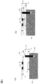
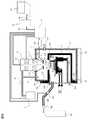
- FIG. 8 shows the entire configuration of the charged particle microscope of the present embodiment.
- the charged particle microscope of the present embodiment also includes the charged particle optical lens barrel 2, a first case (vacuum chamber) 7 for supporting the charged particle optical lens barrel with respect to the apparatus installation surface, and a first case. It is comprised by the 2nd housing
- the operations and functions of these elements or the additional elements added to the elements are substantially the same as those of the first embodiment, and thus detailed description will be omitted.
- the diaphragm holding member 155 is detachably fixed to the upper surface side of the second housing 121, more specifically, the lower surface side of the ceiling plate via a vacuum sealing member.
- the diaphragm 10 is very thin, having a thickness of several nm to several tens of ⁇ m or less, due to the requirement for transmission of the charged particle beam, and therefore may be damaged during aging or preparation for observation. Further, since the diaphragm 10 is thin, direct handling is very difficult. As in the present embodiment, the fact that the diaphragm 10 can be handled not directly but through the diaphragm holding member 155 makes it very easy to handle the diaphragm 10 (particularly, exchange).
- the diaphragm 10 when the diaphragm 10 is broken, it may be replaced together with the diaphragm holding member 155. Even if the diaphragm 10 needs to be replaced directly, the diaphragm holding member 155 is taken out of the apparatus and replacement of the diaphragm 10 is performed. It can be done externally. In addition, it is the same as that of Example 1 in that an aperture member having a hole of about 1 mm 2 or less in area can be used instead of the diaphragm.
- sample holder 401 of the present embodiment is provided with the aforementioned contact preventing member 400.
- the sample 6 can be removed together with the sample table 401 and the contact prevention member 400 to the outside of the apparatus.
- At least one side surface of the second space (the open surface of the second housing 121) can be covered with the lid member 122, and various functions are provided. realizable. This will be explained below.
- the charged particle microscope of the present embodiment has a function of supplying a replacement gas into the second housing.
- the charged particle beam emitted from the lower end of the charged particle optical column 2 passes through the first space 11 maintained at high vacuum, passes through the diaphragm 10 (or the aperture member) shown in FIG. It enters the second space 12 maintained at atmospheric pressure or a desired pressure state or gas state.
- the atmosphere of the second space is atmospheric pressure or a pressure similar to the atmospheric pressure, and is in a state where the degree of vacuum is lower (at a lower degree of vacuum) than at least the first space. In a space with a low degree of vacuum, charged particle beams are scattered by gas molecules, so the mean free path becomes short.
- the scattering probability of the electron beam is proportional to the mass number of the gas molecule. Therefore, if the second space 12 is replaced with gas molecules whose mass number is lighter than the atmosphere, the scattering probability of the charged particle beam decreases, and the charged particle beam can reach the sample. Further, the atmosphere in the passage of the electron beam in at least the second space may be replaced with a gas, even if it is not the whole of the second space.
- the improvement effect of the image S / N can be seen, but the helium gas or hydrogen gas with a lighter mass has the image S / N The improvement effect is large.
- the cover member 122 is provided with the attachment portion (gas introduction portion) of the gas supply pipe 100.
- the gas supply pipe 100 is connected to the gas cylinder 103 by the connection portion 102, whereby the replacement gas is introduced into the second space 12.
- a gas control valve 101 is disposed in the middle of the gas supply pipe 100 to control the flow rate of the replacement gas flowing in the pipe. Therefore, a signal line extends from the gas control valve 101 to the lower control unit 37, and the apparatus user can control the flow rate of the replacement gas on the operation screen displayed on the monitor of the computer 35. Further, the gas control valve 101 may be operated manually to open and close.
- the replacement gas is a light element gas, it easily accumulates in the upper part of the second space 12 and is less likely to be replaced on the lower side. Therefore, it is preferable to provide an opening for communicating the inside and outside of the second space below the mounting position of the gas supply pipe 100 by the lid member 122.
- an opening is provided at the mounting position of the pressure control valve 104.
- An evacuation port may be provided in the second housing 121 or the lid member 122, and the inside of the second housing 121 may be evacuated once to make a slight negative pressure state. In this case, it is not necessary to perform high vacuum evacuation since the amount of atmospheric gas remaining in the second housing 121 may be reduced to a certain amount or less, and rough evacuation is sufficient. After rough evacuation, gas may be introduced from the gas supply pipe 100.
- the degree of vacuum is, for example, 10 5 Pa to 10 3 Pa. If no gas is introduced, even if the gas cylinder 103 is replaced with a vacuum pump, it is possible to form a slight negative pressure state.
- the state of the sample once placed in a vacuum state is changed by evaporation of the moisture. Therefore, as described above, it is preferable to introduce the replacement gas directly from the atmosphere. After the introduction of the replacement gas, the replacement gas can be effectively confined in the second space 12 by closing the opening with a lid member.
- this opening can be used also as a rough exhaust port and an air leak exhaust port. That is, if one of the three-way valves is attached to the lid member 122, one is connected to the rough evacuation vacuum pump, and the other one is fitted with the leak valve, the combined exhaust port can be realized.
- a pressure control valve 104 may be provided instead of the opening described above.
- the pressure control valve 104 has a function of automatically opening the valve when the internal pressure of the second housing 121 reaches 1 atm or higher.
- a pressure control valve having such a function, when the light element gas is introduced, it is automatically opened when the internal pressure reaches 1 atm or more, and atmospheric gas components such as nitrogen and oxygen are discharged to the outside of the apparatus, It is possible to fill the inside of the device with an element gas.
- the illustrated gas cylinder 103 may be provided to the charged particle microscope or may be attached by the apparatus user after the fact.
- the space in which the sample is placed can be controlled to an arbitrary degree of vacuum from atmospheric pressure (about 10 5 Pa) to about 10 3 Pa.
- atmospheric pressure about 10 5 Pa
- the pressure in the electron beam column changes in conjunction It is difficult to control the sample chamber to a pressure of atmospheric pressure (about 10 5 Pa) to about 10 3 Pa.
- the second space and the first space are separated by the thin film, the pressure of the atmosphere in the second space surrounded by the second housing 121 and the lid member 122 Gas species can be freely controlled.
- the sample chamber can be controlled to a pressure of atmospheric pressure (about 10 5 Pa) to about 10 3 Pa, which has hitherto been difficult to control. In addition to observation at atmospheric pressure (about 10 5 Pa), it is possible to continuously change the pressure in the vicinity thereof to observe the state of the sample.
- the charged particle microscope of the present embodiment is provided with a sample stage 5 as a moving means of the observation field of view.
- the sample stage 5 is provided with an XY drive mechanism in the in-plane direction and a Z-axis drive mechanism in the height direction.
- a support plate 107 serving as a bottom plate for supporting the sample stage 5 is attached to the lid member 122, and the sample stage 5 is fixed to the support plate 107.
- the support plate 107 is attached so as to extend toward the inside of the second housing 121 toward the surface of the lid member 122 facing the second housing 121.
- Support shafts extend from the Z-axis drive mechanism and the XY drive mechanism, respectively, and are connected to the operation knob 108 and the operation knob 109, respectively.
- the apparatus user adjusts the position of the sample 6 in the second housing 121 by operating these operation knobs 108 and 109.
- the charged particle microscope of the present embodiment is provided with a lid member support member 19 and a bottom plate 20 on the bottom surface of the first housing 7 and the lower surface of the lid member 122, respectively.
- the lid member 122 is removably fixed to the second housing 121 via the vacuum sealing member 125.
- the cover member support member 19 is also removably fixed to the bottom plate 20, and as shown in FIG. 9, the cover member 122 and the cover member support member 19 may be removed entirely from the second housing 121. It is possible.
- the electrical wiring etc. are abbreviate
- the bottom plate 20 is provided with a support 18 used as a guide at the time of removal.
- the support 18 is stored in a storage portion provided on the bottom plate 20, and is configured to extend in the withdrawal direction of the lid member 122 at the time of removal.
- the support 18 is fixed to the lid support member 19 so that when the lid 122 is removed from the second housing 121, the lid 122 and the charged particle microscope main body are not completely separated. ing. This can prevent the sample stage 5 or the sample 6 from falling.
- the Z-axis operation knob of the sample stage 5 is turned to move the sample 6 away from the diaphragm 10.
- the pressure control valve 104 is opened, and the inside of the second housing is opened to the atmosphere.
- the lid member 122 is pulled out to the side opposite to the apparatus main body.
- the sample 6 can be replaced.
- the lid member 122 is pushed into the second housing 121, and after fixing the lid member 122 to the mating portion 132 with a fastening member not shown, a replacement gas is introduced as necessary.
- the above-described operation can also be performed when a high voltage is applied to the optical lens 2 inside the electron optical lens barrel 2 or when an electron beam is emitted from the charged particle beam source 8. Therefore, the charged particle microscope of the present embodiment can quickly start observation after sample exchange.
- the contact prevention member 400 is provided on the sample table 401 as in the first embodiment. The sample 6 can be removed together with the sample table 401 and the contact prevention member 400 to the outside of the apparatus.
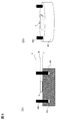
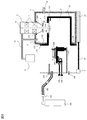
- FIG. 10 shows an entire configuration diagram of the charged particle microscope of the present example in a state of being used as a high vacuum SEM.
- the control system is the same as that of FIG.
- the mounting positions of the gas supply pipe 100 and the pressure control valve 104 are The charged particle microscope in the state of being closed by the cover member 130 is shown.
- the diaphragm 10 and the diaphragm holding member 155 are removed from the second housing 121 by this back and forth operation, the first space 11 and the second space 12 can be connected, and the inside of the second housing is a vacuum pump It becomes possible to evacuate at 4. Thereby, high vacuum SEM observation becomes possible in the state where the 2nd case 121 was attached.
- the sample stage 5 and its operation knobs 108 and 109, the gas supply pipe 100, and the pressure control valve 104 are all attached to the lid member 122 in a concentrated manner. Therefore, the apparatus user can perform the operation of the operation knobs 108 and 109, the sample replacement operation, or the gas supply pipe 100 and the pressure adjustment valve 104 on the same surface of the first housing. Therefore, the state for observation under atmospheric pressure and the state for observation under high vacuum are switched as compared with a charged particle microscope having a configuration in which the above-mentioned components are attached separately to the other surface of the sample chamber. The operability at the time of improvement has been greatly improved.
- a contact monitor that detects a contact state between the second housing 121 and the lid member 122 may be provided to monitor whether the second space is closed or open.
- an X-ray detector and a photodetector may be provided to enable EDS analysis and detection of fluorescent light.
- the X-ray detector or the light detector may be disposed in either the first space 11 or the second space 12.
- a voltage may be applied to the sample stage 5.
- high energy can be given to emitted electrons and transmitted electrons from the sample 6, which makes it possible to increase the signal amount, and the image S / N is improved.
- a SEM that can be used as a high vacuum SEM and can easily be observed under a gas atmosphere at atmospheric pressure or a slight negative pressure is realized.
- the observation can be performed by introducing a replacement gas, the charged particle microscope of the present embodiment can obtain an image having a better S / N than the charged particle microscope of the first embodiment.
- the structural example which intended the desk-top type electron microscope was demonstrated in the present Example, it is also possible to apply this Example to a large sized charged particle microscope.
- the entire apparatus or the charged particle optical column is supported by the housing on the apparatus installation surface by a housing, but in the case of a large charged particle microscope, the entire apparatus may be mounted on a mount If the first housing 7 is placed on a gantry, the configuration described in the present embodiment can be diverted to a large charged particle microscope as it is.
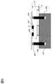
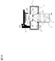
- FIG. 1 A third embodiment is shown in FIG. In the following, the description of the same parts as in the first and second embodiments will be omitted.
- the apparatus comprises a support (vacuum chamber) 7 connected to the charged particle optical lens barrel 2, a sample stage 5 disposed under the atmosphere, and a control system for controlling these.
- a diaphragm 10 is disposed below the housing (vacuum chamber) 7. When the charged particle microscope is used, the interior of the charged particle optical lens barrel 2 and the first housing is evacuated by the vacuum pump 4.
- the lower part of the diaphragm 10 provided in the housing 7 is provided with a sample stage 5 disposed under the atmosphere.
- the sample stage 5 is provided with a height adjustment function that allows at least the sample 6 to approach the diaphragm 10.
- the sample 6 can be made to approach the diaphragm 10 by turning the operation unit 204 or the like.
- an XY drive mechanism that moves in the in-plane direction of the sample may be provided.
- the contact preventing member 400 is provided on the sample table 401 as in the first and second embodiments. The sample 6 can be removed together with the sample table 401 and the contact prevention member 400 to the outside of the apparatus.
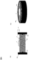
- FIG. 12 shows a configuration diagram of the charged particle microscope of the present embodiment.
- the vacuum pump and the control system are omitted and illustrated.
- the housing 7 and the charged particle optical lens barrel 2 which are vacuum chambers are supported by a column, a support or the like with respect to the apparatus installation surface.
- the operations / functions of the respective elements or additional elements added to the respective elements are substantially the same as those of the above-described embodiment, and thus the detailed description will be omitted.
- a sample stage 5 is provided on the diaphragm to bring the sample 6 and the diaphragm 10 out of contact with each other. That is, the sample on the lower side of the sample 6 in the drawing is observed.
- the operation unit 204 for operating the sample stage 5 it is possible to bring the lower side in the drawing of the sample close to the diaphragm 10 part.
- the contact preventing member 400 is provided on the sample table 401 as in the above-described embodiment, it is possible to perform the contact prevention and the distance control of the sample and the diaphragm.
- the present invention is not limited to the embodiments described above, but includes various modifications.
- the embodiments described above are described in detail in order to explain the present invention in an easy-to-understand manner, and are not necessarily limited to those having all the configurations described.
- part of the configuration of one embodiment can be replaced with the configuration of another embodiment, and the configuration of another embodiment can be added to the configuration of one embodiment.
- each of the configurations, functions, processing units, processing means, etc. described above may be realized by hardware, for example, by designing part or all of them with an integrated circuit.
- each configuration, function, etc. described above may be realized by software by the processor interpreting and executing a program that realizes each function.
- Information such as a program, a table, and a file for realizing each function can be placed in a memory, a hard disk, a recording device such as an SSD (Solid State Drive), or a recording medium such as an IC card, an SD card, or a DVD.
- SSD Solid State Drive
- a recording medium such as an IC card, an SD card, or a DVD.
- control lines and information lines indicate what is considered to be necessary for the description, and not all control lines and information lines in the product are necessarily shown. In practice, almost all configurations may be considered to be mutually connected.
- Optical lens 2 Electron optical (charged particle optics) column 3: Detector 4: Vacuum pump 5: Sample stage 6: Sample 7: 7: First housing 8: Electron source (charged particles Source: 9: open surface 10: diaphragm 11: first space 12: second space 14: leak valve 16: vacuum piping 17: sample stage 18: post 19: for lid member Support member, 20: base plate, 35: computer, 36: upper control unit, 37: lower control unit, 43, 44: communication line, 100: gas supply pipe, 101: valve for gas control, 102: connection unit, 103: Gas cylinder, 104: pressure control valve, 105: limiting member, 106: camera, 107: support plate, 108, 109: operation knob, 121: second housing, 122, 130: lid member, 123, 124, 125, 126 , 128, 129: vacuum sealing member, 1 1: main body, 132: joint portion, 152: signal amplifier, 155: diaphragm holding member, 156, 157
Landscapes
- Chemical & Material Sciences (AREA)
- Analytical Chemistry (AREA)
- Analysing Materials By The Use Of Radiation (AREA)
Priority Applications (4)
| Application Number | Priority Date | Filing Date | Title |
|---|---|---|---|
| DE112013003728.9T DE112013003728T5 (de) | 2012-09-14 | 2013-07-03 | Mit einem Strahl geladener Teilchen arbeitende Vorrichtung und Probenbeobachtungsverfahren |
| US14/422,186 US9240305B2 (en) | 2012-09-14 | 2013-07-03 | Charged particle beam device and sample observation method |
| CN201380041332.8A CN104520965A (zh) | 2012-09-14 | 2013-07-03 | 带电粒子束装置以及试样观察方法 |
| KR1020157000314A KR20150022983A (ko) | 2012-09-14 | 2013-07-03 | 하전 입자선 장치 및 시료 관찰 방법 |
Applications Claiming Priority (2)
| Application Number | Priority Date | Filing Date | Title |
|---|---|---|---|
| JP2012202188A JP5936497B2 (ja) | 2012-09-14 | 2012-09-14 | 荷電粒子線装置及び試料観察方法 |
| JP2012-202188 | 2012-09-14 |
Publications (1)
| Publication Number | Publication Date |
|---|---|
| WO2014041876A1 true WO2014041876A1 (ja) | 2014-03-20 |
Family
ID=50278010
Family Applications (1)
| Application Number | Title | Priority Date | Filing Date |
|---|---|---|---|
| PCT/JP2013/068201 WO2014041876A1 (ja) | 2012-09-14 | 2013-07-03 | 荷電粒子線装置及び試料観察方法 |
Country Status (6)
Families Citing this family (5)
| Publication number | Priority date | Publication date | Assignee | Title |
|---|---|---|---|---|
| JP6302702B2 (ja) * | 2014-02-27 | 2018-03-28 | 株式会社日立ハイテクノロジーズ | 走査電子顕微鏡および画像生成方法 |
| JP6711655B2 (ja) * | 2016-03-18 | 2020-06-17 | 株式会社日立ハイテクサイエンス | 集束イオンビーム装置 |
| KR101798473B1 (ko) * | 2016-05-30 | 2017-11-17 | (주)코셈 | 고분해능 주사전자현미경 |
| KR102181455B1 (ko) * | 2018-12-28 | 2020-11-23 | 참엔지니어링(주) | 시료 관찰 장치 및 방법 |
| CN115210844A (zh) * | 2020-03-02 | 2022-10-18 | 国立研究开发法人物质·材料研究机构 | 观测对象气体的渗透扩散路径观测装置和观测对象气体的测量方法、点缺陷位置检测装置和点缺陷位置检测方法、以及观测用试样 |
Citations (5)
| Publication number | Priority date | Publication date | Assignee | Title |
|---|---|---|---|---|
| JPS59146145A (ja) * | 1983-02-09 | 1984-08-21 | Akashi Seisakusho Co Ltd | 試料移動装置 |
| JPH11162388A (ja) * | 1997-12-01 | 1999-06-18 | Jeol Ltd | 荷電粒子線装置における試料装置 |
| JP2007324099A (ja) * | 2006-06-05 | 2007-12-13 | Hitachi High-Technologies Corp | 試料微動システム、及び荷電粒子線装置 |
| JP2008218342A (ja) * | 2007-03-07 | 2008-09-18 | Hitachi High-Technologies Corp | 電子顕微鏡 |
| WO2012104942A1 (ja) * | 2011-01-31 | 2012-08-09 | 株式会社 日立ハイテクノロジーズ | 荷電粒子線装置 |
Family Cites Families (5)
| Publication number | Priority date | Publication date | Assignee | Title |
|---|---|---|---|---|
| JP2004039708A (ja) * | 2002-07-01 | 2004-02-05 | Nikon Corp | 荷電粒子線露光装置 |
| WO2009049235A2 (en) * | 2007-10-12 | 2009-04-16 | Deka Products Limited Partnership | Systems, devices and methods for cardiopulmonary treatment and procedures |
| JP5253800B2 (ja) | 2007-12-26 | 2013-07-31 | 日本電子株式会社 | 試料保持体及び観察・検査方法並びに観察・検査装置 |
| JP6207824B2 (ja) * | 2012-10-01 | 2017-10-04 | 株式会社日立ハイテクノロジーズ | 荷電粒子線装置、隔膜の位置調整方法および隔膜位置調整ジグ |
| JP6051014B2 (ja) * | 2012-10-29 | 2016-12-21 | 株式会社日立ハイテクノロジーズ | 試料格納用容器、荷電粒子線装置、及び画像取得方法 |
-
2012
- 2012-09-14 JP JP2012202188A patent/JP5936497B2/ja not_active Expired - Fee Related
-
2013
- 2013-07-03 DE DE112013003728.9T patent/DE112013003728T5/de not_active Ceased
- 2013-07-03 US US14/422,186 patent/US9240305B2/en not_active Expired - Fee Related
- 2013-07-03 CN CN201380041332.8A patent/CN104520965A/zh active Pending
- 2013-07-03 KR KR1020157000314A patent/KR20150022983A/ko not_active Abandoned
- 2013-07-03 WO PCT/JP2013/068201 patent/WO2014041876A1/ja active Application Filing
Patent Citations (5)
| Publication number | Priority date | Publication date | Assignee | Title |
|---|---|---|---|---|
| JPS59146145A (ja) * | 1983-02-09 | 1984-08-21 | Akashi Seisakusho Co Ltd | 試料移動装置 |
| JPH11162388A (ja) * | 1997-12-01 | 1999-06-18 | Jeol Ltd | 荷電粒子線装置における試料装置 |
| JP2007324099A (ja) * | 2006-06-05 | 2007-12-13 | Hitachi High-Technologies Corp | 試料微動システム、及び荷電粒子線装置 |
| JP2008218342A (ja) * | 2007-03-07 | 2008-09-18 | Hitachi High-Technologies Corp | 電子顕微鏡 |
| WO2012104942A1 (ja) * | 2011-01-31 | 2012-08-09 | 株式会社 日立ハイテクノロジーズ | 荷電粒子線装置 |
Also Published As
| Publication number | Publication date |
|---|---|
| US20150235803A1 (en) | 2015-08-20 |
| JP5936497B2 (ja) | 2016-06-22 |
| CN104520965A (zh) | 2015-04-15 |
| JP2014056783A (ja) | 2014-03-27 |
| US9240305B2 (en) | 2016-01-19 |
| KR20150022983A (ko) | 2015-03-04 |
| DE112013003728T5 (de) | 2015-05-21 |
Similar Documents
| Publication | Publication Date | Title |
|---|---|---|
| JP5699023B2 (ja) | 荷電粒子線装置 | |
| JP5930922B2 (ja) | 荷電粒子線装置及び試料観察方法 | |
| JP5936484B2 (ja) | 荷電粒子線装置及び試料観察方法 | |
| JP6207824B2 (ja) | 荷電粒子線装置、隔膜の位置調整方法および隔膜位置調整ジグ | |
| JP5825964B2 (ja) | 検査又は観察装置及び試料の検査又は観察方法 | |
| WO2014069470A1 (ja) | 試料格納容器、荷電粒子線装置、及び画像取得方法 | |
| JP5923412B2 (ja) | 観察装置および光軸調整方法 | |
| WO2015129446A1 (ja) | 走査電子顕微鏡および画像生成方法 | |
| JP5909431B2 (ja) | 荷電粒子線装置 | |
| WO2014041876A1 (ja) | 荷電粒子線装置及び試料観察方法 | |
| JP6169703B2 (ja) | 隔膜取付部材および荷電粒子線装置 | |
| JP6419965B2 (ja) | 試料高さ調整方法及び観察システム | |
| JP6272384B2 (ja) | 荷電粒子線装置 | |
| JP5923632B2 (ja) | 荷電粒子線装置 | |
| JP2016001629A (ja) | 試料観察方法 |
Legal Events
| Date | Code | Title | Description |
|---|---|---|---|
| 121 | Ep: the epo has been informed by wipo that ep was designated in this application |
Ref document number: 13837166 Country of ref document: EP Kind code of ref document: A1 |
|
| ENP | Entry into the national phase |
Ref document number: 20157000314 Country of ref document: KR Kind code of ref document: A |
|
| WWE | Wipo information: entry into national phase |
Ref document number: 14422186 Country of ref document: US Ref document number: 1120130037289 Country of ref document: DE Ref document number: 112013003728 Country of ref document: DE |
|
| 122 | Ep: pct application non-entry in european phase |
Ref document number: 13837166 Country of ref document: EP Kind code of ref document: A1 |