WO2014041849A1 - 積層型二次電池 - Google Patents
積層型二次電池 Download PDFInfo
- Publication number
- WO2014041849A1 WO2014041849A1 PCT/JP2013/063491 JP2013063491W WO2014041849A1 WO 2014041849 A1 WO2014041849 A1 WO 2014041849A1 JP 2013063491 W JP2013063491 W JP 2013063491W WO 2014041849 A1 WO2014041849 A1 WO 2014041849A1
- Authority
- WO
- WIPO (PCT)
- Prior art keywords
- positive electrode
- outer peripheral
- secondary battery
- negative electrode
- electrode
- Prior art date
- Legal status (The legal status is an assumption and is not a legal conclusion. Google has not performed a legal analysis and makes no representation as to the accuracy of the status listed.)
- Ceased
Links
Images



Classifications
-
- H—ELECTRICITY
- H01—ELECTRIC ELEMENTS
- H01M—PROCESSES OR MEANS, e.g. BATTERIES, FOR THE DIRECT CONVERSION OF CHEMICAL ENERGY INTO ELECTRICAL ENERGY
- H01M4/00—Electrodes
- H01M4/02—Electrodes composed of, or comprising, active material
- H01M4/13—Electrodes for accumulators with non-aqueous electrolyte, e.g. for lithium-accumulators; Processes of manufacture thereof
-
- H—ELECTRICITY
- H01—ELECTRIC ELEMENTS
- H01M—PROCESSES OR MEANS, e.g. BATTERIES, FOR THE DIRECT CONVERSION OF CHEMICAL ENERGY INTO ELECTRICAL ENERGY
- H01M50/00—Constructional details or processes of manufacture of the non-active parts of electrochemical cells other than fuel cells, e.g. hybrid cells
- H01M50/40—Separators; Membranes; Diaphragms; Spacing elements inside cells
- H01M50/463—Separators, membranes or diaphragms characterised by their shape
- H01M50/466—U-shaped, bag-shaped or folded
-
- H—ELECTRICITY
- H01—ELECTRIC ELEMENTS
- H01M—PROCESSES OR MEANS, e.g. BATTERIES, FOR THE DIRECT CONVERSION OF CHEMICAL ENERGY INTO ELECTRICAL ENERGY
- H01M10/00—Secondary cells; Manufacture thereof
- H01M10/04—Construction or manufacture in general
- H01M10/0463—Cells or batteries with horizontal or inclined electrodes
-
- H—ELECTRICITY
- H01—ELECTRIC ELEMENTS
- H01M—PROCESSES OR MEANS, e.g. BATTERIES, FOR THE DIRECT CONVERSION OF CHEMICAL ENERGY INTO ELECTRICAL ENERGY
- H01M10/00—Secondary cells; Manufacture thereof
- H01M10/05—Accumulators with non-aqueous electrolyte
- H01M10/052—Li-accumulators
- H01M10/0525—Rocking-chair batteries, i.e. batteries with lithium insertion or intercalation in both electrodes; Lithium-ion batteries
-
- H—ELECTRICITY
- H01—ELECTRIC ELEMENTS
- H01M—PROCESSES OR MEANS, e.g. BATTERIES, FOR THE DIRECT CONVERSION OF CHEMICAL ENERGY INTO ELECTRICAL ENERGY
- H01M10/00—Secondary cells; Manufacture thereof
- H01M10/05—Accumulators with non-aqueous electrolyte
- H01M10/058—Construction or manufacture
- H01M10/0585—Construction or manufacture of accumulators having only flat construction elements, i.e. flat positive electrodes, flat negative electrodes and flat separators
-
- Y—GENERAL TAGGING OF NEW TECHNOLOGICAL DEVELOPMENTS; GENERAL TAGGING OF CROSS-SECTIONAL TECHNOLOGIES SPANNING OVER SEVERAL SECTIONS OF THE IPC; TECHNICAL SUBJECTS COVERED BY FORMER USPC CROSS-REFERENCE ART COLLECTIONS [XRACs] AND DIGESTS
- Y02—TECHNOLOGIES OR APPLICATIONS FOR MITIGATION OR ADAPTATION AGAINST CLIMATE CHANGE
- Y02E—REDUCTION OF GREENHOUSE GAS [GHG] EMISSIONS, RELATED TO ENERGY GENERATION, TRANSMISSION OR DISTRIBUTION
- Y02E60/00—Enabling technologies; Technologies with a potential or indirect contribution to GHG emissions mitigation
- Y02E60/10—Energy storage using batteries
-
- Y—GENERAL TAGGING OF NEW TECHNOLOGICAL DEVELOPMENTS; GENERAL TAGGING OF CROSS-SECTIONAL TECHNOLOGIES SPANNING OVER SEVERAL SECTIONS OF THE IPC; TECHNICAL SUBJECTS COVERED BY FORMER USPC CROSS-REFERENCE ART COLLECTIONS [XRACs] AND DIGESTS
- Y02—TECHNOLOGIES OR APPLICATIONS FOR MITIGATION OR ADAPTATION AGAINST CLIMATE CHANGE
- Y02P—CLIMATE CHANGE MITIGATION TECHNOLOGIES IN THE PRODUCTION OR PROCESSING OF GOODS
- Y02P70/00—Climate change mitigation technologies in the production process for final industrial or consumer products
- Y02P70/50—Manufacturing or production processes characterised by the final manufactured product
Definitions
- the present invention relates to a stacked secondary battery in which a battery element in which a positive electrode and a negative electrode are stacked via a separator is sealed with an exterior material.
- a stacked secondary battery such as a lithium ion battery in which a positive electrode and a negative electrode are stacked with a separator interposed therebetween increases the area of the positive electrode and the negative electrode or increases the number of stacked positive and negative electrodes. Since it is easy to increase the capacity per battery, it is suitable as a battery having a large charge / discharge capacity.
- the positive electrode is coated with a slurry for a positive electrode in which a particulate positive electrode active material, a conductive material, a binder, etc. are mixed on the surface of a strip-shaped aluminum foil of a current collector. It is manufactured by cutting it. Similarly, apply negative electrode slurry in which particulate negative electrode active material, conductive material, binder, etc. are mixed on the surface of the strip-shaped copper foil of the current collector, and then cut to a predetermined size. Manufactured.
- the separator in the laminated secondary battery is a microporous film made of a synthetic resin such as polyethylene or polypropylene, and the positive electrode and the negative electrode larger than the outer shape are interposed between the positive electrode and the negative electrode.
- a microporous film made of a synthetic resin such as polyethylene or polypropylene
- the positive electrode and the negative electrode larger than the outer shape are interposed between the positive electrode and the negative electrode.
- FIG. 7 at least one of the positive electrode and the negative electrode is inserted into a bag formed in the outer peripheral portion of the separator 300 in advance and processed into a bag shape, and laminated. What produced the laminated body 400 is known. Further, as shown in FIG.
- the outer periphery welded portion of the separator is divided into an inner periphery welded portion 510 and an outer periphery heat welded portion 520 in order to achieve both strength of the bag and prevention of wrinkles due to heat shrinkage.
- JP 2003-17112 A Japanese Patent Laid-Open No. 9-82361 Japanese Patent Laid-Open No. 10-188938
- the separator at the position corresponding to one of the four corners of the electrode can be It turned out to be difficult to prevent tearing. This seems to be because the force generated during contraction is concentrated on the apex of the corner of the separator.
- the electrode in order to process the corner of the electrode into an arc shape, it is possible to manufacture the electrode by blanking by punching with a closed cutting tool having a cutting blade that matches the electrode shape, but it cannot be punched at once.
- a large cutting blade is required when the electrode shape is large. Therefore, the width direction and the length direction of the electrode are cut separately, and after cutting one of the width direction or the length direction by an arbitrary method, the corner of the electrode is cut when the other is pushed off.
- a cutting tool having a cutting blade that is a quadrant is used.
- the electrode breaks through the bag-shaped separator due to a phenomenon such as sharp corners due to tearing of the cutting residue. There was a possibility that the active material dropped out.
- a current collector coated with an active material is welded with an electrode having a chamfered portion that chamfers at least one intersection of two adjacent sides of an outer peripheral line of a projection portion on a plane parallel to the current collector. It is a laminated type secondary battery inserted in the bag-shaped separator formed in the bag shape by the intermittent welding part which formed the part intermittently.
- the heat welding portion on the outer periphery of the bag-like separator including the positive electrode and the negative electrode is provided with a portion that is intermittently welded at intervals.
- the corners of the electrodes are chamfered in a state in which a continuous thermal welding portion is provided in the longitudinal direction, a high-quality secondary battery can be provided without breaking the separator.
- the chamfered portion having a specific shape is formed at the corner of at least one of the positive electrode and the negative electrode.
- the chamfered portion of the present invention is formed at least on the positive electrode or the negative electrode located closest to the battery container, the electrode and the container are short-circuited by breaking through an insulating film or the like disposed between the battery container and the like. The possibility of doing so can be reduced. Furthermore, a lithium ion battery excellent in productivity can be provided.
- the negative electrode current collector facing the surface on which the positive electrode active material is formed must be It arrange
- the area of the positive electrode is one of the factors that govern the size of the battery capacity. Therefore, if the chamfered portion of the present invention is formed at least on the positive electrode, the amount of the electrode active material to be removed can be reduced, so that the effect of increasing the battery capacity can be obtained.
- FIG. 1 is a diagram for explaining a manufacturing process of a positive electrode and a negative electrode.
- FIG. 2 is a diagram for explaining an embodiment of the laminated secondary battery of the present invention.
- 2A is a front view
- FIG. 2B is a cross-sectional view taken along the line A-A ′ in FIG. 1A and showing an enlarged view of the stacking direction.
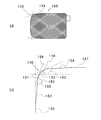
- FIG. 3 is a plan view illustrating a chamfered portion of the positive electrode according to one embodiment of the present invention.
- FIG. 3A is a plan view illustrating a positive electrode having a chamfered portion.
- FIG. 3B is an enlarged view of the chamfered portion.
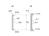
- FIG. 4 is a view for explaining an example of a cutting tool used for forming the chamfered portion of the present invention and the conventional one.
- FIG. 4A is a diagram for explaining an example of a conventional cutting tool
- FIG. 4B is a diagram for explaining an example of a cutting tool used for manufacturing the positive electrode of the present invention.
- FIG. 5 is a diagram for explaining another embodiment of the present invention.
- FIG. 6 is a diagram for explaining an example of a stacked secondary battery using a bag-shaped separator.
- FIG. 7 is a diagram for explaining another example of a stacked secondary battery using a bag-shaped separator.
- FIG. 8 is a diagram for explaining the positive electrode in which the positioning of the positive electrode base material and the cutting tool has shifted.
- FIG. 1 is a diagram illustrating a manufacturing process of a positive electrode and a negative electrode. Since the positive electrode and the negative electrode are produced by the same method except for the constituent materials, the positive electrode will be described in the following description.
- the positive electrode base material is a positive electrode base material in which a slurry-like positive electrode mixture is intermittently applied to both surfaces on a positive electrode current collector made of a strip-shaped aluminum foil, dried and then compressed by a roller press or the like to be molded. It is produced by cutting to a predetermined size.
- lithium-containing composite oxides such as lithium manganese composite oxide and lithium cobalt composite oxide, conductive materials such as carbon black, binders such as polyvinylidene fluoride, and the like are used.
- a slurry dispersed in 2-pyrrolidone can be used.
- the positive electrode active material layer 103 is intermittently formed on the positive electrode base material 102 at a portion indicated by a shaded portion. Further, as shown by a broken line in FIG. 1A, the positive electrode active material layer is formed by intermittently forming the positive electrode active material layer 103 in an area larger than the positive electrode part outline 104 indicating the size of the positive electrode to be manufactured. Yes. Next, as shown in FIG. 1B, both side surface portions 105a and 105b in the length direction of the strip-like positive electrode base material 102 are cut along a predetermined positive electrode outer shape line. Next, as shown in FIG.
- the positive electrode active material layer 103 applied intermittently in the length direction is cut along a first cutting line 110 formed of a curved portion at a straight portion and both ends.
- the positive electrode extraction tab 106 is cut integrally with the positive electrode extraction tab forming portion 113 by the second cutting line 112 for taking out the positive electrode extraction tab. Since the positive electrode active material application part 114 remains at the tip of the positive electrode extraction tab formation part 113, the positive electrode active material application part 114 is cut to form the positive electrode extraction tab 115 as shown in FIG. 1D.
- the electrode 100 is completed. Further, the positive electrode 100 has a chamfered portion 150 whose corners are chamfered in a curved shape.
- FIGS. 1A to 1D the example in which the positive electrode extraction tab is located on one side of the center line in the width direction has been described. However, the center line may coincide with the center line of the positive electrode extraction tab.
- the negative electrode comprises a strip-shaped copper foil on a negative electrode current collector, a carbon material that absorbs and releases lithium ions, a conductive material such as carbon black, a binder such as polyvinylidene fluoride, and the like. Disperse in pyrrolidone to form a slurry, and apply this slurry-like negative electrode mixture on both sides of the negative electrode current collector intermittently, and after drying, compress it with a roller press or the like to perform molding.
- a negative electrode can be produced in the same manner as the positive electrode by manufacturing the material and cutting it into a predetermined size.
- FIG. 2 is a diagram for explaining an embodiment of the laminated secondary battery of the present invention.
- 2A is a front view
- FIG. 2B is a cross-sectional view taken along the line AA ′ in FIG. 2A and showing an enlarged view of the stacking direction.
- the stacked secondary battery 1 includes a stacked body 400 in which a positive electrode 100 and a negative electrode 200 are stacked with a separator 300 interposed therebetween.
- the positive electrode extraction tab 115 and the negative electrode extraction tab 215 are taken out from the laminate 400 in the same direction, and the positive electrode extraction tab 115 connected to the positive electrode from the sealing portion 510 of the film-shaped exterior material 500 and the negative electrode extraction tab connected to the negative electrode 215 is taken out.
- the separator 300 covering the positive electrode 100 has a bag shape around the positive electrode 100 by an adhesion method that does not continuously form a welded portion.
- the separator one produced by cleaving a film by stretching to obtain a porous member is generally used. Therefore, the separator has a direction that easily contracts and a direction that does not easily contract, depending on the stretching direction applied during manufacture. For this reason, a direction that does not easily contract is arranged in the longitudinal direction of the side of the electrode, and a direction that easily contracts is arranged in the short direction.
- a material having strength and heat resistance such as nylon and polyethylene terephthalate is provided on the outer surface side of the aluminum foil, and a material having good heat weldability such as polypropylene and polyethylene is provided on the inner surface side. Laminated layers can be used.
- the exterior material of the stacked secondary battery is not limited to the film-like exterior material as described above, and a metal exterior container or the like may be used.
- FIG. 3 is a plan view for explaining the chamfered portion of the positive electrode.
- FIG. 3A is a plan view illustrating a positive electrode having a chamfered portion.
- FIG. 3B is an enlarged view of the chamfered portion.
- the outer peripheral portion of the positive electrode has a chamfered portion 150 that is chamfered in a curved shape at least one of the intersections of two adjacent sides of the outer peripheral line of the projection portion on a plane parallel to the positive electrode current collector,
- the curved portion 152 of the chamfered portion 150 has a shape different from the quadrant 151 shown by a broken line in FIG. 3A, and both end portions are connected to the two outer peripheral connection portions 153 and 154.
- All chamfered portions of the outer peripheral portion of the positive electrode including corners 159, 160 formed by tangents 157, 158 and the outer peripheral connecting portions 153, 154 at intersections 155, 156 of the curved portion 152 and the outer peripheral connecting portions 153, 154
- At least one of the angles formed by the tangent line and the outer peripheral connection portion is an obtuse angle.
- the angle formed between the tangent at the intersection of the curved portion and the outer peripheral connection portion and the line of the outer peripheral connection portion is the two tangent lines extending in both directions at the two intersections of the curved portion and the outer peripheral connection portion. It means the angle formed between the tangent line on the side intersecting with each other from the intersection point and the line of the outer peripheral connection part.
- the positive electrode base is caused by a slight deviation between the end of the quadrant and the outer peripheral connection portion as in the case of chamfering by the quadrant shown by a broken line in FIG. It is possible to prevent a problem that the positive electrode is not cut from the material or a step is generated at the cut portion.
- the chamfered portion forms a connecting portion between the tangent line at the intersection of the curved portion and the outer peripheral connecting portion and the curved portion where the angle formed by the line of the outer peripheral connecting portion is an obtuse angle, so that the positive electrode active material from the corner portion
- the positive electrode has been described, but the negative electrode can also be manufactured in the same manner as the positive electrode.
- the battery electrode of the present invention has a larger outer shape than the chamfered portion indicated by the quadrant 151, so that the battery electrode of the battery electrode is compared with the case where the chamfered portion formed by the quadrant is formed. The effect that the effective area increases and the battery capacity increases can also be obtained.
- the outer peripheral lines of at least some of the corners of the positive electrode and the negative electrode have a curved shape as described above. It is more preferable to use the same shape when chamfering the corner. Moreover, it is preferable that at least one or more of the angles formed by the tangent line and the line of the outer peripheral connection portion is an obtuse angle.
- the angle formed between the tangent line and the outer peripheral connection portion means the angle formed between the tangent line in the direction where two tangent lines intersect at the two intersections between the curved portion and the outer peripheral connection portion and the outer peripheral connection portion line. To do.
- FIG. 4 is a view for explaining an example of a cutting tool used for forming the chamfered portion of the present invention and the conventional one.
- a cutting tool 600 shown in FIG. 4A is a diagram for explaining an example of a conventional cutting tool, and is a diagram showing a cross section cut along a plane parallel to the current collector surface at the time of cutting.
- the cutting tool 600 includes a cutting blade 601.
- the cutting blade 601 has a flat surface portion 602 and curved surface portions 603a and 603b connected to the flat surface portion 602.
- the length between both ends of the cutting blade 601 is the same as the width of the positive electrode width PW cut from the positive electrode base material, and the cross section formed in the curved surface portions 603a and 603b is a quadrant-shaped cutting blade.
- the end portion can be cut to coincide with the end face of the positive electrode base material, and a quadrant connected to the outer peripheral portion can be formed.
- a quadrant is formed in the chamfered portion when the end portion of the cutting tool is coincident with the end surface of the positive electrode base material.
- the end portion of the cutting blade does not coincide with the end surface of the positive electrode base material, there is a problem that a part of the cutting blade cannot be cut or a curved surface cannot be chamfered.
- a cutting tool 610 shown in FIG. 4B is a view for explaining an example of a cutting tool used for manufacturing the positive electrode of the present invention, and is a view showing a cross section cut along a plane parallel to the current collector surface at the time of cutting. is there.
- the cutting tool 610 used for manufacturing the positive electrode of the present invention includes a cutting blade 611, and the cutting blade 611 has a flat surface portion 612 and curved surface portions 613a and 613b connected thereto.
- the length of the flat portion of the cutting blade 611 is shorter than the width of the positive electrode width PW produced from the positive electrode base material, and the length of the curved surface portions 613a and 613b is compared with the conventional quadrant provided at both ends. Long.
- the length between the both ends of the width direction of the positive electrode base material of a cutting tool is characterized by being longer than the length of the positive electrode width PW produced from a positive electrode base material.
- the length between both ends in the width direction of the positive electrode base material of the cutting blade 611 is slightly longer than the positive electrode width PW.
- the length is preferably 1 to 1.06 times considering the tolerance of each member.
- the curved surface shape of the cutting blade can be an arc shape that is easy to manufacture, but any curved line, such as an elliptical arc, can be used as long as the linear distance from the end of the flat surface to the tip of the curved surface increases.
- the curved shape can be used.
- FIG. 5 is a diagram for explaining another embodiment of the present invention.
- FIG. 5A is a plan view for explaining the positive electrode
- FIG. 5B is an enlarged view for explaining the chamfered portion.
- the positive electrode 100 has a chamfered portion 150 in which at least one intersection of two adjacent sides of the outer peripheral line of the projected portion on a plane parallel to the positive electrode current collector is chamfered in a curved shape. Both end portions of the curved portion 152 are connected to the two outer peripheral connection portions 153 and 154.
- At least one or more of the angles 159, 160 formed between the tangents 157, 158 and the outer peripheral connection portions 153, 154 at the intersections 155, 156 between the curved portion 152 and the outer peripheral connection portions 153, 154 are obtuse angles. It is said. Further, the outer peripheral connection portions 153 and 154 are inclined so that the outer peripheral connection portions 153 and 154 form an acute angle from the outer peripheral lines 165 and 167 of the positive electrode toward the curved surface portion 150. As a result, each corner portion forms a curved outer peripheral line with the curved surface and the outer peripheral connection portion, so that the effect of preventing the active material from falling off can be enhanced.
- the chamfered portion of the positive electrode and the negative electrode are chamfered at the time of chamfering at least a part of the corners in the insertion direction of the bag-like separator or the battery outer container.
- an exterior is provided by a film-like exterior material, or A battery can be produced by storing the battery in a metal battery can and sealing the electrolyte solution after injection.
- an electrode having a chamfered portion in which at least one of the intersections of two adjacent sides of the outer peripheral line of the projection portion on the surface parallel to the current collector is chamfered is welded to the current collector coated with the active material.
- the corners of the electrodes inserted into the bag-shaped separator by chamfering the corners of the electrodes inserted into the bag-shaped separator and continuously welding the longitudinal direction of the outer peripheral portion of the bag-shaped separator, it is possible to prevent the separator from shrinking and breaking.
- the corners of the electrode can be made to have a predetermined shape so that dust such as cutting residue portions during chamfering processing, as well as burrs and corner portions after the cutting residue portions are removed, do not occur. It is also possible to prevent omission, breakage and omission of the active material.
- Example 1 Lithium manganate (LiMn2O4), carbon black, and polyvinylidene fluoride were blended and dispersed in N-methyl-2-pyrrolidone to prepare a positive electrode mixture.
- the obtained positive electrode mixture was applied to both sides of an aluminum foil having a thickness of 20 ⁇ m, dried, and then subjected to compression molding with a roller press to produce positive electrodes each having a positive electrode layer having a thickness of 80 ⁇ m on both sides.
- the prepared positive electrode is attached to a cutting device, and at least a part of the chamfered portion has a curved portion and at least one outer peripheral connecting portion connected to the curved portion, and the curved portion and the outer peripheral connecting portion Cutting was carried out by changing the angle formed between the tangent line at the intersection and the line of the outer peripheral connection portion.
- disconnected by the quadrant circle was also done as a comparative example. The same tendency was observed when cutting at two or more locations to obtain the desired shape, or when cutting only one location to obtain the desired shape. The results are shown below. Evaluation criteria Active material drop-off rate: When the current collector of the active material application part was exposed by visual inspection, it was considered as defective.
- Burr occurrence rate Visual inspection with a magnifying glass was performed, and those having a burr size of 60 ⁇ m or more were regarded as defective.
- Punching defect rate If a step difference in punching deviation was confirmed by visual inspection, it was determined as defective.
- High-temperature environment test An electrode was inserted into a bag-shaped separator made of a polypropylene microporous film in which only the side corresponding to the side adjacent to the terminal was continuously welded.
- Table 2 shows the test results obtained by observing the number of exposed electrodes exposed when the heat-welded portion of the separator is broken when left in a high temperature environment of 80 ° C. to 130 ° C. for 1 hour. The test was performed using 10 samples each.
- the electrode is exposed from 120 ° C. without chamfering, whereas the electrode is not exposed even at 130 ° C. by chamfering.
- the laminated secondary battery according to the present invention has a chamfered portion having a curved surface with a specific shape at the corners of the positive electrode and the negative electrode, the positive electrode and the negative electrode can be removed from the positive electrode substrate and the negative electrode substrate. Even when a positional shift occurs during manufacturing by cutting, a stacked secondary battery in which the positive electrode active material and the negative electrode active material are not dropped from the corners can be provided.
- DESCRIPTION OF SYMBOLS 102 ... Positive electrode base material, 103 ... Positive electrode active material layer, 104 ... Positive electrode part outline, 105a, 105b ... Both side parts, 106 ... Positive electrode cut body, 110 ... -1st cutting line, 112 ... 2nd cutting line, 113 ... Positive electrode extraction tab formation part, 114 ... Positive electrode active material application part, 115 ... Positive electrode extraction tab, 150 ... Chamfering part, 165, 167 ... outer periphery of the positive electrode, 200 ... negative electrode, 300 ... separator, 400 ... laminate, 115 ... positive electrode extraction tab, 118 ... cutting residue part, 215 .. Negative electrode extraction tab, 500... Film-shaped exterior material, 510...
Landscapes
- Chemical & Material Sciences (AREA)
- Chemical Kinetics & Catalysis (AREA)
- Electrochemistry (AREA)
- General Chemical & Material Sciences (AREA)
- Engineering & Computer Science (AREA)
- Manufacturing & Machinery (AREA)
- Materials Engineering (AREA)
- Secondary Cells (AREA)
- Battery Electrode And Active Subsutance (AREA)
Description
本発明は、正極電極と負極電極とをセパレーターを介して積層した電池要素を外装材で封口した積層型二次電池に関する。
正極電極と負極電極とをセパレーターを介して積層したリチウムイオン電池等の積層型二次電池は、正極、負極の面積を大きくしたり、積層する正極、負極の枚数を増加したりすることによって単位電池当たりの容量を大きくすることが容易であるので、充放電容量が大きな電池として好適である。
リチウムイオン電池では、正極電極は、集電体の帯状のアルミニウム箔面に、粒子状の正極活物質、導電性材料、結着剤等を混合した正極用スラリーを塗布、乾燥後,所定の大きさに切断することによって製造されている。負極電極も同様に、集電体の帯状の銅箔面に、粒子状の負極活物質、導電性材料、結着剤等を混合した負極用スラリーを塗布、乾燥後、所定の大きさに切断して製造されている。
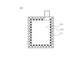
また、積層型二次電池におけるセパレーターは、ポリエチレン、ポリプロピレン等の合成樹脂製の微多孔性フィルムを用い、正極電極および負極電極の外形よりも大きいものを正極電極と負極電極の間に介在させて積層するものや、図7に示す様に正極電極および負極電極の少なくとも一方の電極をあらかじめセパレーター300の外周部に熱溶着部500を形成して袋状に加工したものに挿入して積層して積層体400を作製したものが知られている。また、図8のように袋状セパレーターには、袋の強度と熱収縮によるシワの発生防止を両立するために、セパレータの外周の溶着部を内周溶着部510と外周熱溶着部520に分け、内周側を間隔を設けて溶着する提案がなされている(特許文献1参照)。
正極電極、負極電極の角部が直角になるように切断されていると、角部がセパレータを破ったり、角形電池容器の内壁に接触するなどして、正極及び負極活物質が脱落したり、電極が折れなどが生じる曲がったりする不都合が生じ、このため電池の内部ショートによる不良率が増加すると言う問題があった。この問題点を解決するために、正極電極、負極電極のそれぞれの少なくとも角形電池容器への挿入側の角部を円弧形状とすることが提案されている(特許文献2、3参照)。
なお、電極の角部を円弧状に加工するためには、帯状の部材にスラリーを塗布して形成した正極電極基材、負極電極基材を所定の寸法に切断する場合、切断された電極の角部が4分円になるような切断刃で押し切る切断工具を使用することができる。
セパレーターが収縮した際に電極が袋状のセパレーターを突き破らないようにするために、電極の最外周部をすべて連続的に溶着しても、電極の四隅のいずれかに対応する位置のセパレーターが破れることを防ぐのが難しいことが判明した。これは、収縮時に発生する力がセパレーターの角部の頂点に集中するためと思われる。
一方、電極の角部を円弧状に加工するためには、電極形状に合致した切断刃を有する閉じた切断工具によって打ち抜くブランキングによって電極を製造することも可能であるが、一度に打ちぬけない大きな形状には適用できないことはもちろん、電極形状が大きくなると大型の切断刃が必要となるなど、大量生産には適さないという問題がある。そこで、電極の幅方向と長さ方向とは別々に切断することになり、幅方向または長さ方向のいずれか一方を任意の方法で切断したのち、他方を押し切りする際に電極の角部が4分円になるような切断刃をもった切断工具を用いることになる。
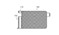
しかしこの場合、切断刃の端部と、あらかじめ切断した電極の辺とが一致しない場合には、図6に示すように正極電極基材から切断された正極電極用切断体106には、面取り部の端部が正極電極基材102の外周部と一致しないために、所定の切断ができなくなる。その結果、切断残渣部118を生じる等の問題が起きるために、電池に使用可能なものを得ることができないことがあった。
また、切断刃の端部と電極辺の位置の不一致がわずかの場合には、切断残渣部がちぎれる等が原因で、角部が鋭くなる等の現象が生じて電極が袋状のセパレーターを突き破る可能性や、活物質が脱落するなどの可能性があった。
本発明は、活物質を塗布した集電体を、集電体に平行な面への投影部の外周線の隣り合う2辺の交点の少なくとも一箇所を面取りした面取り部を有する電極を、溶着部を間欠的に形成した間欠溶着部によって袋状に形成した袋状セパレーターに挿入した積層型二次電池である。
本発明に係る積層型二次電池によれば、正極電極と負極電極とを入れて袋状セパレーターの外周における熱溶着部は間隔を設けて間欠的に溶着した部分を備えを備えている。また、長手方向においては更に連続的な熱溶着部を備えた状態で、電極の角部を面取りしているのでセパレーターが破れることなく高品質の二次電池を提供することができる。
また、本発明に係る積層型二次電池によれば、正極電極、負極電極の少なくとも一方の電極の角部には特定の形状を有する面取り部を形成している。したがって、正極電極基材、負極電極基材から切断工具によって切断する際に、相互の位置ずれ等が生じても、所望の形状の面取り部が形成されるので、生産性が向上し、品質が安定した二次電池を提供することができる。
また、本発明に係る積層型二次電池によれば、正極電極、負極電極の少なくとも一方の電極の角部には特定の形状を有する面取り部を形成している。したがって、正極電極基材、負極電極基材から切断工具によって切断する際に、相互の位置ずれ等が生じても、所望の形状の面取り部が形成されるので、生産性が向上し、品質が安定した二次電池を提供することができる。
また、少なくとも最も電池容器の近くに位置する正極電極または負極電極に本発明の面取り部を形成しておけば、電池容器と間とに配置される絶縁膜等を突き破って電極と容器とがショートする可能性を低減することができる。更に、生産性にも優れたリチウムイオン電池を提供することができる。
リチウムイオン二次電池に適用する場合、負極集電体上にリチウムのデンドライトが発生しないようにするために、正極電極活物質が形成された面と対向する負極集電体上には、必ず負極活物質を形成するように配置している。したがって、相対的に正極電極は負極電極よりも外形寸法が小さくなる傾向がある。
すなわち、正極電極の面積は電池容量の大きさを支配する要素の一つになっている。そこで本発明の面取り部を少なくとも正極電極に形成すれば、取り除かれる電極活物質の量を少なくなるので、その分だけ電池容量を増加させるという効果を得ることもできる。
リチウムイオン二次電池に適用する場合、負極集電体上にリチウムのデンドライトが発生しないようにするために、正極電極活物質が形成された面と対向する負極集電体上には、必ず負極活物質を形成するように配置している。したがって、相対的に正極電極は負極電極よりも外形寸法が小さくなる傾向がある。
すなわち、正極電極の面積は電池容量の大きさを支配する要素の一つになっている。そこで本発明の面取り部を少なくとも正極電極に形成すれば、取り除かれる電極活物質の量を少なくなるので、その分だけ電池容量を増加させるという効果を得ることもできる。
以下に、図面を参照して本発明を説明する。
リチウムイオン二次電池を例に挙げて本発明を説明する。
図1は、正極電極、負極電極の製造工程を説明する図である。
正極電極、負極電極は、その構成材料が相違するのみで同様の方法によって作製しているので、以下の説明においては正極電極について説明する。
正極電極は、帯状のアルミニウム箔からなる正極集電体上に、スラリー状の正極合剤を間欠的に両面に塗布し、乾燥後、ローラープレス機等によって圧縮して成型を行い正極電極基材から所定の大きさに切断することによって作製する。
正極合剤としては、リチウムマンガン複合酸化物、リチウムコバルト複合酸化物等のリチウムを含有する複合酸化物と、カーボンブラック等の導電性材料、ポリフッ化ビニリデン等の結着剤等をN-メチル-2-ピロリドンに分散させてスラリー状としたものを用いることができる。
リチウムイオン二次電池を例に挙げて本発明を説明する。
図1は、正極電極、負極電極の製造工程を説明する図である。
正極電極、負極電極は、その構成材料が相違するのみで同様の方法によって作製しているので、以下の説明においては正極電極について説明する。
正極電極は、帯状のアルミニウム箔からなる正極集電体上に、スラリー状の正極合剤を間欠的に両面に塗布し、乾燥後、ローラープレス機等によって圧縮して成型を行い正極電極基材から所定の大きさに切断することによって作製する。
正極合剤としては、リチウムマンガン複合酸化物、リチウムコバルト複合酸化物等のリチウムを含有する複合酸化物と、カーボンブラック等の導電性材料、ポリフッ化ビニリデン等の結着剤等をN-メチル-2-ピロリドンに分散させてスラリー状としたものを用いることができる。
図1Aに示すように、正極電極基材102には、網掛け部で示す部分に正極活物質層103を間欠的に形成している。また、図1Aにおいて破線で示すように正極活物質層は、製造する正極電極の外形の大きさを示す正極電極部外形線104よりも大きな面積で正極活物質層103を間欠的に形成している。
次に、図1Bに示すように、帯状の正極電極基材102の長さ方向の両側面部105a、105bを所定の正極電極外形線に沿って切断する。次いで、図1Cに示すように長さ方向に間欠的に塗布した正極活物質層103を、直線部と両端部に曲面状部からなる第一切断線110に沿って切断する。
また、正極引出タブを取り出す第二切断線112によって正極引出タブ形成部113と一体に切断して正極電極用切断体106を作製する。
正極引出タブ形成部113の先端部には正極活物質塗布部114が残っているので、図1Dに示すように、正極活物質塗布部114を切断して正極引出タブ115を形成することによって正極電極100が完成する。
また、正極電極100には、その角部の外周を曲線状に面取りした面取り部150を有している。
図1A~図1Dでは、正極引出タブが幅方向の中心線の一方の側に位置する例について説明したが、前記中心線と正極引出タブの中心線が一致するものであっても良い。
次に、図1Bに示すように、帯状の正極電極基材102の長さ方向の両側面部105a、105bを所定の正極電極外形線に沿って切断する。次いで、図1Cに示すように長さ方向に間欠的に塗布した正極活物質層103を、直線部と両端部に曲面状部からなる第一切断線110に沿って切断する。
また、正極引出タブを取り出す第二切断線112によって正極引出タブ形成部113と一体に切断して正極電極用切断体106を作製する。
正極引出タブ形成部113の先端部には正極活物質塗布部114が残っているので、図1Dに示すように、正極活物質塗布部114を切断して正極引出タブ115を形成することによって正極電極100が完成する。
また、正極電極100には、その角部の外周を曲線状に面取りした面取り部150を有している。
図1A~図1Dでは、正極引出タブが幅方向の中心線の一方の側に位置する例について説明したが、前記中心線と正極引出タブの中心線が一致するものであっても良い。
負極電極は、帯状の銅箔を負極集電体上に、リチウムイオンを吸蔵、放出する炭素材料、カーボンブラック等の導電性材料、ポリフッ化ビニリデン等の結着剤等をN-メチル-2-ピロリドンに分散させてスラリー状とし、このスラリー状の負極合剤を負極集電体上に間欠的に両面に塗布し、乾燥後、ローラープレス機等によって圧縮して成型を行って、負極電極基材を製造して所定の大きさに切断することによって正極電極と同様の方法で負極電極を作製することができる。
図2は、本発明の積層型二次電池の一実施形態を説明する図である。図2Aは、正面図を示し、図2Bは、図2AのA-A’の位置における断面図であって積層方向を拡大した図を示す。
積層型二次電池1は、正極電極100と負極電極200がセパレーター300を介して積層した積層体400を有している。積層体400から同一方向に正極引出タブ115および負極引出タブ215を取り出しており、フィルム状外装材500の封口部510から正極電極に接続した正極引出タブ115と、負極電極に接続した負極引出タブ215を取り出している。
積層型二次電池1は、正極電極100と負極電極200がセパレーター300を介して積層した積層体400を有している。積層体400から同一方向に正極引出タブ115および負極引出タブ215を取り出しており、フィルム状外装材500の封口部510から正極電極に接続した正極引出タブ115と、負極電極に接続した負極引出タブ215を取り出している。
正極電極100を覆ったセパレーター300は、正極電極100の周囲を溶着部を連続的に形成しない接着方法によって袋状としている。
セパレーターは、フィルムを延伸によって開裂して多孔性部材とすることで製造したものが一般に用いられている。したがって、セパレーターには製造時に加えられた延伸方向によって、収縮しやすい方向と収縮しにくい方向が存在している。
このため、電極の辺の長手方向には収縮しにくい方向を配置し、短手方向には収縮しやすい方向を配置している。
本発明では、連続溶着部を端子に隣接した辺に対応するセパレーターの辺のみに設けることが好ましい。これによって長手方向の収縮に耐える力を大きくすることができ、温度上昇時にセパレーターの収縮による影響を受けにくいリチウムイオン二次電池を提供することができる。
セパレーターは、フィルムを延伸によって開裂して多孔性部材とすることで製造したものが一般に用いられている。したがって、セパレーターには製造時に加えられた延伸方向によって、収縮しやすい方向と収縮しにくい方向が存在している。
このため、電極の辺の長手方向には収縮しにくい方向を配置し、短手方向には収縮しやすい方向を配置している。
本発明では、連続溶着部を端子に隣接した辺に対応するセパレーターの辺のみに設けることが好ましい。これによって長手方向の収縮に耐える力を大きくすることができ、温度上昇時にセパレーターの収縮による影響を受けにくいリチウムイオン二次電池を提供することができる。
また、フィルム状外装材には、アルミニウム箔の外面側にはナイロン、ポリエチレンテレフタレート等の強度および耐熱性を有する部材を、内面側には、ポリプロピレン、ポリエチレン等の熱溶着性が良好な材料をそれぞれ積層したものを用いることができる。積層型二次電池の外装材には、上記したようなフィルム状外装材に限らず金属製の外装容器等を用いたものであってもよい。
次に、本発明の正極電極、負極電極の面取り部について説明する。
図3は、正極電極の面取り部を説明する平面図である。図3Aは、面取り部を形成した正極電極を説明する平面図である。また、図3Bは面取り部を拡大した図である。
正極電極の外周部には、正極集電体に平行な面への投影部の外周線の隣り合う2辺の交点の少なくとも一箇所を曲線状に面取りした面取り部150を有しており、前記面取り部150の曲線部152は図3Aにおいて破線で示す4分円151とは異なる形状を有し、両端部が二つの外周接続部153、154と接続している。
図3は、正極電極の面取り部を説明する平面図である。図3Aは、面取り部を形成した正極電極を説明する平面図である。また、図3Bは面取り部を拡大した図である。
正極電極の外周部には、正極集電体に平行な面への投影部の外周線の隣り合う2辺の交点の少なくとも一箇所を曲線状に面取りした面取り部150を有しており、前記面取り部150の曲線部152は図3Aにおいて破線で示す4分円151とは異なる形状を有し、両端部が二つの外周接続部153、154と接続している。
前記曲線部152と前記外周接続部153、154との交点155、156における接線157、158と前記外周接続部153、154とがなす角159、160を含む正極電極の外周部のすべての面取り部での前記接線と前記外周接続部とのなす角のうちの少なくとも1つ以上が鈍角であることを特徴としている。
本発明において、曲線部と外周接続部との交点における接線と外周接続部の線とのなす角とは、前記曲線部と前記外周接続部との二つの交点において両方向に延びる二つの接線の前記交点から互いに交わる側に位置する側の接線と前記外周接続部の線とのなす角度を意味する。
本発明において、曲線部と外周接続部との交点における接線と外周接続部の線とのなす角とは、前記曲線部と前記外周接続部との二つの交点において両方向に延びる二つの接線の前記交点から互いに交わる側に位置する側の接線と前記外周接続部の線とのなす角度を意味する。
面取り部を以上のような形状とすることによって、図3において、破線で示す4分円による面取りの場合のように、4分円の端部と外周接続部とのわずかなずれによって正極電極基材から正極電極が切断されなかったり、あるいは切断部に段差を生じるという問題の発生を防止することができる。
その結果、面取り部には曲線部と外周接続部との交点における接線と外周接続部の線とのなす角が鈍角である曲線部との接続部を形成するので、角部からの正極活物質の脱落を防止した、特性が優れた積層型二次電池を提供することができる。
以上の説明では正極電極について説明をしたが、負極電極についても正極電極と同様に作製することができる。
また、本発明の電池電極は、図3で説明したように、4分円151で示す面取り部よりも外形が大きくなるので、4分円からなる面取り部を形成した場合に比べて電池電極の有効面積が大きくなり、電池容量が大きくなるという効果も得ることができる。
その結果、面取り部には曲線部と外周接続部との交点における接線と外周接続部の線とのなす角が鈍角である曲線部との接続部を形成するので、角部からの正極活物質の脱落を防止した、特性が優れた積層型二次電池を提供することができる。
以上の説明では正極電極について説明をしたが、負極電極についても正極電極と同様に作製することができる。
また、本発明の電池電極は、図3で説明したように、4分円151で示す面取り部よりも外形が大きくなるので、4分円からなる面取り部を形成した場合に比べて電池電極の有効面積が大きくなり、電池容量が大きくなるという効果も得ることができる。
また、本発明の積層型二次電池においては、正極電極、負極電極の角部の少なくとも一部の角部の外周線を上記のような曲線状となるようにすることが好ましいが、すべての角部の面取り加工時に同様の形状とすることがより好ましい。
また、前記接線と前記外周接続部の線とのなす角の少なくとも1つ以上が鈍角とすることが好ましい。接線と外周接続部の線とのなす角度とは、前記曲線部と前記外周接続部との二つの交点における二つの接線が交わる方向の部分の接線と外周接続部の線とのなす角度を意味する。
また、前記接線と前記外周接続部の線とのなす角の少なくとも1つ以上が鈍角とすることが好ましい。接線と外周接続部の線とのなす角度とは、前記曲線部と前記外周接続部との二つの交点における二つの接線が交わる方向の部分の接線と外周接続部の線とのなす角度を意味する。
本発明の積層型二次電池の正極電極、負極電極の面取り部の形成方法の一例について説明する。
図4は、本発明および従来の面取り部の形成に用いる切断工具の一例を説明する図である。 図4Aに示す切断工具600は、従来の切断工具の一例を説明する図であり、切断時の集電体面に平行な面で切断した断面を示す図である。
切断工具600は、切断刃601を備えており、切断刃601には平面部602とそれに接続する曲面部603a、603bを有している。
切断刃601の両端部間の長さは、正極電極基材から切断する正極電極幅PWの幅と同じであって、曲面部603a、603bに形成された断面が4分円状の切断刃の端部を正極電極基材の端面に一致させて切断し、外周部に接続した4分円を形成することができる。 このような切断刃を有する切断工具を用いた場合には、切断工具の端部が正極電極基材の端面に一致している場合には面取り部には4分円が生じる。
しかしながら、切断刃の端部が正極電極基材の端面に一致しない場合には一部が切断できなかったり、曲面状の面取りができないという問題が生じていた。
図4は、本発明および従来の面取り部の形成に用いる切断工具の一例を説明する図である。 図4Aに示す切断工具600は、従来の切断工具の一例を説明する図であり、切断時の集電体面に平行な面で切断した断面を示す図である。
切断工具600は、切断刃601を備えており、切断刃601には平面部602とそれに接続する曲面部603a、603bを有している。
切断刃601の両端部間の長さは、正極電極基材から切断する正極電極幅PWの幅と同じであって、曲面部603a、603bに形成された断面が4分円状の切断刃の端部を正極電極基材の端面に一致させて切断し、外周部に接続した4分円を形成することができる。 このような切断刃を有する切断工具を用いた場合には、切断工具の端部が正極電極基材の端面に一致している場合には面取り部には4分円が生じる。
しかしながら、切断刃の端部が正極電極基材の端面に一致しない場合には一部が切断できなかったり、曲面状の面取りができないという問題が生じていた。
図4Bに示す切断工具610は、本発明の正極電極を製造するために使用する切断工具の一例を説明する図であり、切断時の集電体面に平行な面で切断した断面を示す図である。
本発明の正極電極の製造に使用する切断工具610は、切断刃611を備えており、切断刃611には平面部612とそれに接続する曲面部613a、613bを有している。
切断刃611の平面部の長さは、正極電極基材から作製する正極電極幅PWの幅よりも短く、曲面部613a、613bの長さは、従来の両端部に設けた4分円に比べて長い。 また、切断工具の正極電極基材の幅方向の両端部間の長さは、正極電極基材から作製する正極電極幅PWの長さよりも長いことを特徴としている。
本発明の正極電極の製造に使用する切断工具610は、切断刃611を備えており、切断刃611には平面部612とそれに接続する曲面部613a、613bを有している。
切断刃611の平面部の長さは、正極電極基材から作製する正極電極幅PWの幅よりも短く、曲面部613a、613bの長さは、従来の両端部に設けた4分円に比べて長い。 また、切断工具の正極電極基材の幅方向の両端部間の長さは、正極電極基材から作製する正極電極幅PWの長さよりも長いことを特徴としている。
例えば、切断刃611の正極電極基材の幅方向の両端部間の長さは、正極電極幅PWに比べてわずかに長くすることが好ましい。具体的には、各部材の公差を考慮して1~1.06倍の長さとすることが好ましい。
切断工具の切断刃の長さをこのような長さとすることによって、切断工程において正極電極基材と切断工具との間に位置ずれが生じた場合であっても電極の面取り部に曲面部を形成することができる。
以上の説明では、正極電極基材の正極引出タブを取り出していない側を切断する工具について述べたが、正極引出タブを取り出す側を切断する側の切断工具には、正極引出タブ形成部を切断可能な切断工具を用いることができる。
切断工具の切断刃の長さをこのような長さとすることによって、切断工程において正極電極基材と切断工具との間に位置ずれが生じた場合であっても電極の面取り部に曲面部を形成することができる。
以上の説明では、正極電極基材の正極引出タブを取り出していない側を切断する工具について述べたが、正極引出タブを取り出す側を切断する側の切断工具には、正極引出タブ形成部を切断可能な切断工具を用いることができる。
切断刃の曲面部形状は、製作加工が容易な円弧形状とすることができるが、平面部の端部から曲面の先端部までの直線距離が増加する曲線であれば,楕円弧をはじめとする任意の曲面形状のものを使用することができる。
図5は、本発明の他の実施態様を説明する図である。
図5Aは、正極電極を説明する平面図であり、図5Bは、面取り部を拡大して説明する図である。
正極電極100は、正極集電体に平行な面への投影部の外周線の隣り合う2辺の交点の少なくとも一箇所を曲線状に面取りした面取り部150を有しており、前記面取り部150の曲線部152は両端部が二つの外周接続部153、154と接続している。
前記曲線部152と前記外周接続部153、154との交点155、156における接線157、158と前記外周接続部153、154とのなす角159、160の少なくとも1つ以上が鈍角であることを特徴としている。
また、外周接続部153、154は、正極電極の外周線165、167から曲面部150に向けて外周接続部153、154が鋭角をなすように傾斜している。その結果、それぞれの角部は曲面と外周接続部は曲線状外周線を形成するので、活物質の脱落の防止効果を高めることができる。
図5Aは、正極電極を説明する平面図であり、図5Bは、面取り部を拡大して説明する図である。
正極電極100は、正極集電体に平行な面への投影部の外周線の隣り合う2辺の交点の少なくとも一箇所を曲線状に面取りした面取り部150を有しており、前記面取り部150の曲線部152は両端部が二つの外周接続部153、154と接続している。
前記曲線部152と前記外周接続部153、154との交点155、156における接線157、158と前記外周接続部153、154とのなす角159、160の少なくとも1つ以上が鈍角であることを特徴としている。
また、外周接続部153、154は、正極電極の外周線165、167から曲面部150に向けて外周接続部153、154が鋭角をなすように傾斜している。その結果、それぞれの角部は曲面と外周接続部は曲線状外周線を形成するので、活物質の脱落の防止効果を高めることができる。
このような形状とすることによって、図3において破線で示す4分円によって面取りする場合に、4分円の端部と外周接続部とのずれによって切断されなかったり、あるいは段差を生じたりという問題の発生を防止することができる。その結果、面取り部には所望の曲面を形成することができるので、角部からの正極活物質の脱落を防止した特性が優れたリチウムイオン二次電池を提供することができる。
また、本発明の積層型二次電池においては、正極電極、負極電極を袋状セパレーター、あるいは電池外装容器に挿入方向の角部の少なくとも一部の角部の面取り加工時において面取り部を本発明のようなとすることが好ましいが、すべての角部の面取り加工時に本発明のような曲面形状に加工することがより好ましい。
以上の様にして作製した正極電極、負極電極をセパレーターを介して積層して、充放電電流を取り出す電極引出タブを接合した電池要素を作製した後、フィルム状外装材によって外装を設けるか、または、金属製の電池缶に収納し、電解液を注入の後に封口することによって電池を作製することができる。
また、活物質を塗布した集電体を、集電体に平行な面への投影部の外周線の隣り合う2辺の交点の少なくとも一箇所が面取りされた面取り部を有する電極を、溶着部を間欠的に形成した間欠溶着部によって袋状に形成した袋状セパレーターに挿入した後に、対極と積層して充放電電流を取り出す電極引出タブを接合した電池要素を作製した後、フィルム状外装材によって外装を設けるか、または、金属製の電池缶に収納し、電解液を注入の後に封口することによって電池を作製することができる。
また、袋状セパレーターの中に挿入する電極の角部を面取り加工し、袋状セパレーターの外周部の長手方向を連続的に溶着することで、セパレーターが収縮して破れることを防ぐことができる。また、面取り加工の際に切断残渣部等のゴミや、切断残渣部が取り除かれた後のバリや角部の発生が生じないように、電極の角部を所定の形状にすることで電極の脱落、折れおよび活物質の脱落を防ぐことも可能である。
実施例1
リチウムマンガン酸(LiMn2O4)、カーボンブラック、ポリフッ化ビニリデンを配合して、N-メチル-2-ピロリドンに分散してさせて正極合剤を調製した。
得られた正極合剤を厚さ20μmのアルミニウム箔の両面に塗布し、乾燥後、ローラープレス機で圧縮成型を行なって、両面にそれぞれ80μm厚さの正極電極層を有する正極電極を作製した。
作製した正極電極の切断試験と、切断した正極電極を袋状セパレーターに挿入して高温度で放置して観察する高温環境試験を行った。その結果を表に示す。
リチウムマンガン酸(LiMn2O4)、カーボンブラック、ポリフッ化ビニリデンを配合して、N-メチル-2-ピロリドンに分散してさせて正極合剤を調製した。
得られた正極合剤を厚さ20μmのアルミニウム箔の両面に塗布し、乾燥後、ローラープレス機で圧縮成型を行なって、両面にそれぞれ80μm厚さの正極電極層を有する正極電極を作製した。
作製した正極電極の切断試験と、切断した正極電極を袋状セパレーターに挿入して高温度で放置して観察する高温環境試験を行った。その結果を表に示す。
切断試験
作製した正極電極を切断装置に取り付けて、面取り部の少なくとも一部が曲線部と前記曲線部に接続する少なくとも一つ以上の外周接続部を有し、前記曲線部と前記外周接続部との交点における接線と前記外周接続部の線とのなす角を変えて切断を行った。また、比較例として4分円で切断した試験も行った。
二個所以上の切断を行って所望の形状とした場合も、一個所のみの切断によって所望の形状とした場合も同様の傾向が見られたので、1個所の切断を行った場合について評価を行い、その結果を以下に示す。
評価基準
活物質脱落率:目視により活物質塗布部の集電体が露出している場合は不良とした。
バリ発生率:拡大鏡による目視で確認を行い、バリ寸法が60μm以上のものを不良とした。
打ち抜き加工不良率:目視により打ち抜きズレの段差が確認された場合は不良とした。
これらの結果を表1に示す。
作製した正極電極を切断装置に取り付けて、面取り部の少なくとも一部が曲線部と前記曲線部に接続する少なくとも一つ以上の外周接続部を有し、前記曲線部と前記外周接続部との交点における接線と前記外周接続部の線とのなす角を変えて切断を行った。また、比較例として4分円で切断した試験も行った。
二個所以上の切断を行って所望の形状とした場合も、一個所のみの切断によって所望の形状とした場合も同様の傾向が見られたので、1個所の切断を行った場合について評価を行い、その結果を以下に示す。
評価基準
活物質脱落率:目視により活物質塗布部の集電体が露出している場合は不良とした。
バリ発生率:拡大鏡による目視で確認を行い、バリ寸法が60μm以上のものを不良とした。
打ち抜き加工不良率:目視により打ち抜きズレの段差が確認された場合は不良とした。
これらの結果を表1に示す。
表1
角度 活物質剥離率(%) バリ発生率(%) 打ち抜き加工不良率(%)
4分円で切断 6 11 10
105° 3 1 0
120° 1 0 0
135° 0 0 0
150° 0 0 0
165° 0 0 0
180° 0 0 0
角度 活物質剥離率(%) バリ発生率(%) 打ち抜き加工不良率(%)
4分円で切断 6 11 10
105° 3 1 0
120° 1 0 0
135° 0 0 0
150° 0 0 0
165° 0 0 0
180° 0 0 0
高温環境試験
端子に隣接した辺に対応する辺のみを連続溶着したポリプロピレン製の微多孔性フィルム製袋状セパレーターにた電極を挿入した。
80℃から130℃の高温環境に1時間放置したときに、セパレーターの熱溶着部が破れ、挿入した電極が露出する個数を観察した試験結果を表2に示す。試験は、各10個の試料を用いて行った。
端子に隣接した辺に対応する辺のみを連続溶着したポリプロピレン製の微多孔性フィルム製袋状セパレーターにた電極を挿入した。
80℃から130℃の高温環境に1時間放置したときに、セパレーターの熱溶着部が破れ、挿入した電極が露出する個数を観察した試験結果を表2に示す。試験は、各10個の試料を用いて行った。
表2
電極切断角度 高温放置温度
80℃ 90℃ 100℃ 110℃ 120℃ 130℃
試験1 なし 0 0 0 0 2 8
試験2 4分円 0 0 0 0 0 0
試験3 105度 0 0 0 0 0 0
試験4 120度 0 0 0 0 0 0
試験5 135度 0 0 0 0 0 0
試験6 150度 0 0 0 0 0 0
試験7 165度 0 0 0 0 0 0
試験8 180度 0 0 0 0 0 0
電極切断角度 高温放置温度
80℃ 90℃ 100℃ 110℃ 120℃ 130℃
試験1 なし 0 0 0 0 2 8
試験2 4分円 0 0 0 0 0 0
試験3 105度 0 0 0 0 0 0
試験4 120度 0 0 0 0 0 0
試験5 135度 0 0 0 0 0 0
試験6 150度 0 0 0 0 0 0
試験7 165度 0 0 0 0 0 0
試験8 180度 0 0 0 0 0 0
面取り加工なしでは120℃から電極が露出してしまうものが発生するのに対して、面取り加工を施すことで、130℃でも電極が露出することがないことが分かる。
本発明の積層型二次電池は、正極電極、負極電極の角部に、特定の形状の曲面を有する面取り部を設けたので、正極電極基材、負極電極基材から正極電極、負極電極を切断によって製造する際に位置ずれが生じた場合であっても、角部からの正極活物質、負極活物質の脱落がない積層型二次電池を提供することができる。
102・・・正極電極基材、103・・・正極活物質層、104・・・正極電極部外形線、105a,105b・・・両側面部、106・・・正極電極用切断体、110・・・第一切断線、112・・・第二切断線、113・・・正極引出タブ形成部、114・・・正極活物質塗布部、115・・・正極引出タブ、150・・・面取り部、165,167・・・正極電極の外周線、200・・・負極電極、300・・・セパレーター、400・・・積層体、115・・・正極引出タブ、118・・・切断残渣部、215・・・負極引出タブ、500・・・フィルム状外装材、510・・・封口部、151・・・4分円、152・・・曲線部、153,154・・・外周接続部、155,156・・・交点、157,158・・・接線、159,160・・・接線と前記外周接続部とがなす角、600・・・切断工具、601・・・切断刃、602・・・平面部、603a,603b・・・曲面部、610・・・切断工具、611・・・切断刃、612・・・平面部、613a,613b・・・曲面部、PW・・・正極電極幅
Claims (8)
- 活物質を塗布した集電体を、集電体に平行な面への投影部の外周線の隣り合う2辺の交点の少なくとも一箇所を面取りした面取り部を有する電極を、溶着部を間欠的に形成した間欠溶着部によって袋状に形成した袋状セパレーターに挿入したことを特徴とする積層型二次電池。
- 前記袋状セパレーターに挿入した前記電極の集電用タブを取り出している辺と隣接する辺に対応する前記袋状セパレーターの少なくとも一辺には、前記間欠溶着部に隣接した連続溶着部を有することを特徴とする請求項1に記載の積層型二次電池。
- 正極活物質を塗布した正極集電体を正極集電体に平行な面への投影部の外周線の隣り合う2辺の交点の少なくとも一箇所を面取りした第一の面取り部を有する正極電極と、
負極活物質を塗布した負極集電体を負極集電体に平行な面への投影部の外周線の隣り合う2辺の交点の少なくとも一箇所を面取りした第二の面取り部を有する負極電極と、
前記正極電極と前記負極電極との間にセパレータを備え、前記第一または第二の面取り部の少なくとも一部が曲線部と前記曲線部に接続する二つの外周接続部を有し、前記曲線部と前記外周接続部との交点における接線と前記外周接続部の線とのなす角の少なくとも1つ以上が鈍角であることを特徴とするを特徴とする請求項1または2記載の積層型二次電池。 - 前記正極電極、前記負極電極は、それぞれ前記正極集電体、前記負極集電体と一体に形成した正極引出タブ、負極引出タブを有することを特徴とする請求項1から3のいずれか1項記載の積層型二次電池。
- 前記外周線が矩形状であることを特徴とする請求項1から4のいずれか1項記載の積層型二次電池。
- 前記外周線が前記外周接続部へ向かって内側へ屈曲部を有することを特徴とする請求項1から5のいずれか1項記載の積層型二次電池。
- 前記曲線部が円弧であることを特徴とする請求項1から6のいずれか1項記載の積層型二次電池。
- リチウムイオン二次電池であることを特徴とする請求項1から7のいずれか1項記載の積層型二次電池。
Applications Claiming Priority (2)
| Application Number | Priority Date | Filing Date | Title |
|---|---|---|---|
| JP2012-200303 | 2012-09-12 | ||
| JP2012200303 | 2012-09-12 |
Publications (1)
| Publication Number | Publication Date |
|---|---|
| WO2014041849A1 true WO2014041849A1 (ja) | 2014-03-20 |
Family
ID=50277985
Family Applications (1)
| Application Number | Title | Priority Date | Filing Date |
|---|---|---|---|
| PCT/JP2013/063491 Ceased WO2014041849A1 (ja) | 2012-09-12 | 2013-05-15 | 積層型二次電池 |
Country Status (1)
| Country | Link |
|---|---|
| WO (1) | WO2014041849A1 (ja) |
Cited By (4)
| Publication number | Priority date | Publication date | Assignee | Title |
|---|---|---|---|---|
| WO2016113656A1 (ja) * | 2015-01-16 | 2016-07-21 | 株式会社半導体エネルギー研究所 | 可撓性を有する蓄電池及び電子機器 |
| CN108963320A (zh) * | 2017-05-18 | 2018-12-07 | 松下知识产权经营株式会社 | 电池 |
| CN114188597A (zh) * | 2021-11-25 | 2022-03-15 | 宁德新能源科技有限公司 | 电化学装置、电池模组及用电设备 |
| JP2022094745A (ja) * | 2020-12-15 | 2022-06-27 | 株式会社豊田自動織機 | 蓄電装置 |
Citations (5)
| Publication number | Priority date | Publication date | Assignee | Title |
|---|---|---|---|---|
| JPH09213377A (ja) * | 1996-01-30 | 1997-08-15 | Ricoh Co Ltd | 角形電池 |
| JP2001052711A (ja) * | 1999-08-05 | 2001-02-23 | Honda Motor Co Ltd | 蓄電池用電極板 |
| JP2008251226A (ja) * | 2007-03-29 | 2008-10-16 | Sharp Corp | 非水電解液二次電池およびその製造方法 |
| JP2011165481A (ja) * | 2010-02-10 | 2011-08-25 | Nec Energy Devices Ltd | 積層型二次電池 |
| JP2011187266A (ja) * | 2010-03-08 | 2011-09-22 | Hitachi Maxell Energy Ltd | 扁平形非水二次電池 |
-
2013
- 2013-05-15 WO PCT/JP2013/063491 patent/WO2014041849A1/ja not_active Ceased
Patent Citations (5)
| Publication number | Priority date | Publication date | Assignee | Title |
|---|---|---|---|---|
| JPH09213377A (ja) * | 1996-01-30 | 1997-08-15 | Ricoh Co Ltd | 角形電池 |
| JP2001052711A (ja) * | 1999-08-05 | 2001-02-23 | Honda Motor Co Ltd | 蓄電池用電極板 |
| JP2008251226A (ja) * | 2007-03-29 | 2008-10-16 | Sharp Corp | 非水電解液二次電池およびその製造方法 |
| JP2011165481A (ja) * | 2010-02-10 | 2011-08-25 | Nec Energy Devices Ltd | 積層型二次電池 |
| JP2011187266A (ja) * | 2010-03-08 | 2011-09-22 | Hitachi Maxell Energy Ltd | 扁平形非水二次電池 |
Cited By (7)
| Publication number | Priority date | Publication date | Assignee | Title |
|---|---|---|---|---|
| WO2016113656A1 (ja) * | 2015-01-16 | 2016-07-21 | 株式会社半導体エネルギー研究所 | 可撓性を有する蓄電池及び電子機器 |
| JPWO2016113656A1 (ja) * | 2015-01-16 | 2017-12-14 | 株式会社半導体エネルギー研究所 | 可撓性を有する蓄電池及び電子機器 |
| CN108963320A (zh) * | 2017-05-18 | 2018-12-07 | 松下知识产权经营株式会社 | 电池 |
| CN108963320B (zh) * | 2017-05-18 | 2024-09-20 | 松下知识产权经营株式会社 | 电池 |
| JP2022094745A (ja) * | 2020-12-15 | 2022-06-27 | 株式会社豊田自動織機 | 蓄電装置 |
| JP7585760B2 (ja) | 2020-12-15 | 2024-11-19 | 株式会社豊田自動織機 | 蓄電装置 |
| CN114188597A (zh) * | 2021-11-25 | 2022-03-15 | 宁德新能源科技有限公司 | 电化学装置、电池模组及用电设备 |
Similar Documents
| Publication | Publication Date | Title |
|---|---|---|
| JP7780774B2 (ja) | 電池 | |
| CN103891024B (zh) | 具备螺旋电极体的电池及其制造方法 | |
| JP5858158B2 (ja) | 二次電池の集電構造 | |
| JP6041394B2 (ja) | 非水電解液二次電池 | |
| JP6250921B2 (ja) | 電池 | |
| JP2010118315A (ja) | 非水電解質電池 | |
| JP2014022116A (ja) | 二次電池用極板及び二次電池用極板の製造方法 | |
| JP6560877B2 (ja) | ラミネート形電池及びその製造方法 | |
| US9786896B2 (en) | Lithium-ion secondary battery | |
| JP7329538B2 (ja) | 二次電池及びその製造方法 | |
| JP2016181345A (ja) | 二次電池の製造方法 | |
| KR20120022071A (ko) | 각형 밀폐 2차전지 | |
| CN105720228A (zh) | 电极体和电极体制造方法 | |
| WO2013031938A1 (ja) | 二次電池 | |
| JP2013182677A (ja) | 積層型蓄電デバイス | |
| WO2014141640A1 (ja) | ラミネート外装電池 | |
| WO2017158986A1 (ja) | 電池セル | |
| WO2020170598A1 (ja) | 電極板及びその製造方法、二次電池及びその製造方法 | |
| CN108604505A (zh) | 蓄电设备及其制造方法 | |
| JP4603857B2 (ja) | リチウムイオン二次電池およびその製造方法 | |
| JP6322947B2 (ja) | 蓄電素子および極板 | |
| WO2020137714A1 (ja) | 二次電池 | |
| JP2008091100A (ja) | 角型リチウムイオン電池 | |
| JP6781074B2 (ja) | 二次電池 | |
| JP3178500U (ja) | リード部材 |
Legal Events
| Date | Code | Title | Description |
|---|---|---|---|
| 121 | Ep: the epo has been informed by wipo that ep was designated in this application |
Ref document number: 13837338 Country of ref document: EP Kind code of ref document: A1 |
|
| NENP | Non-entry into the national phase |
Ref country code: DE |
|
| 122 | Ep: pct application non-entry in european phase |
Ref document number: 13837338 Country of ref document: EP Kind code of ref document: A1 |
|
| NENP | Non-entry into the national phase |
Ref country code: JP |