WO2014038355A1 - シートベルト装置 - Google Patents
シートベルト装置 Download PDFInfo
- Publication number
- WO2014038355A1 WO2014038355A1 PCT/JP2013/071694 JP2013071694W WO2014038355A1 WO 2014038355 A1 WO2014038355 A1 WO 2014038355A1 JP 2013071694 W JP2013071694 W JP 2013071694W WO 2014038355 A1 WO2014038355 A1 WO 2014038355A1
- Authority
- WO
- WIPO (PCT)
- Prior art keywords
- webbing
- sliding
- sliding portion
- anchor
- seat belt
- Prior art date
- Legal status (The legal status is an assumption and is not a legal conclusion. Google has not performed a legal analysis and makes no representation as to the accuracy of the status listed.)
- Ceased
Links
Images

Classifications
-
- B—PERFORMING OPERATIONS; TRANSPORTING
- B60—VEHICLES IN GENERAL
- B60R—VEHICLES, VEHICLE FITTINGS, OR VEHICLE PARTS, NOT OTHERWISE PROVIDED FOR
- B60R22/00—Safety belts or body harnesses in vehicles
- B60R22/18—Anchoring devices
- B60R22/24—Anchoring devices secured to the side, door, or roof of the vehicle
-
- B—PERFORMING OPERATIONS; TRANSPORTING
- B60—VEHICLES IN GENERAL
- B60R—VEHICLES, VEHICLE FITTINGS, OR VEHICLE PARTS, NOT OTHERWISE PROVIDED FOR
- B60R22/00—Safety belts or body harnesses in vehicles
- B60R22/18—Anchoring devices
- B60R2022/1818—Belt guides
Definitions
- the present invention relates to a seat belt device for restraining an occupant to a seat using webbing.
- the seat belt device is installed in the vehicle seat.
- the seat belt device is a safety device for preventing a passenger from jumping forward due to inertial force when a large deceleration is applied to the vehicle due to a sudden stop or a collision.
- the seat belt device restrains an occupant to a seat using belt-shaped webbing.
- the webbing is housed in a retractor installed on the side of the seat on the base side, and the tip side is drawn upward from the retractor and passed through a through anchor on the vehicle interior wall. Then, the webbing that has passed through the through anchor is folded downward, passed through a detachable tongue plate, and then fixed to the anchor plate near the floor.
- the current seat belt device has been devised in various ways so that its safety performance does not deteriorate. For example, when the webbing is suddenly pulled, there is a phenomenon called “jamming” in which the webbing slides sideways in the through-hole of the through anchor and moves toward the end. When such jamming occurs, the webbing pull-out performance is degraded. Therefore, in Patent Document 1, for example, a plurality of convex portions called “projections” are provided at the lower edge in the insertion hole of the through anchor (referred to as a guide anchor in Patent Document 1). Yes. This protrusion is configured to come into contact with the edge of the webbing when the webbing is pulled strongly and the through anchor tilts, thereby preventing jamming by preventing movement of the webbing in the width direction.
- projections a plurality of convex portions
- jamming occurs when the webbing is suddenly pulled in an emergency, for example, when a pretensioner (winding device) or an energy absorption mechanism (a mechanism that relaxes rapid restraint due to webbing) is activated. This is a possible phenomenon. Therefore, it is desirable that the jamming prevention measure is activated only in an emergency, and does not affect the performance (drawability) when pulling out the webbing as much as possible in normal times.
- the present invention has an object to provide a seat belt device that prevents jamming in an emergency and does not affect the pull-out property of a webbing in a normal time.
- a representative configuration of a seat belt device is a seat belt device that restrains a vehicle occupant to a seat, and is attached to a belt-like webbing and a wall portion in a vehicle interior.
- a through anchor through which the webbing is inserted, and the through anchor has a through hole through which the webbing is inserted, and a lower edge of the through hole is a portion where the webbing contacts and slides when the webbing is used.
- the lower edge further includes a plurality of sliding portions alternately arranged in the width direction of the webbing and having different friction coefficients with respect to the webbing.
- a plurality of portions having a low coefficient of friction against webbing are provided on the lower edge of the through anchor. At that time, the sliding portion is provided along the direction in which the webbing extends. According to this, it is possible to set the webbing so as not to inhibit the pullability in the longitudinal direction and to generate resistance in the movement in the width direction.
- the “friction coefficient” includes both constants of dynamic friction coefficient and static friction coefficient. And “the friction coefficients are different” means that the values are different when compared between the dynamic friction coefficients or the static friction coefficients.
- the plurality of sliding parts include a first sliding part and a second sliding part having a smaller coefficient of friction with respect to webbing than the first sliding part.
- the first sliding part and the second sliding part are Each may be provided on the lower edge portion so as to extend along the sliding direction of the webbing. According to this configuration, it is possible to further improve the webbing pull-out property.
- another typical configuration of the seat belt device according to the present invention is a seat belt device that restrains a vehicle occupant to a seat, and includes a belt-like webbing and a wall portion in a vehicle interior. It is equipped with a through anchor through which the webbing is inserted and a pretensioner that tightens the webbing in an emergency, and the through anchor has an insertion hole through which the webbing is inserted, and the lower edge of the insertion hole is when the webbing is used.
- the coating is provided and is removed by a force applied by webbing when the pretensioner is operated to expose the first sliding portion.
- the above webbing normally slides on the second sliding part having a small friction coefficient with respect to the webbing.
- the second sliding portion is removed and the first sliding portion having a large friction coefficient is slid below the second sliding portion. That is, according to the above-described configuration, it is possible to prioritize the pulling-out property of the webbing during normal times, and to prevent jamming by suppressing the side slip of the webbing in an emergency.
- the phenomenon that is removed by friction with the webbing includes an event that the webbing is scraped off by sliding.
- another typical configuration of the seat belt device is a seat belt device for restraining a vehicle occupant to a seat, and includes a belt-like webbing and a wall portion in a vehicle interior.
- a through anchor that is attached and the webbing is inserted; and an energy absorption mechanism that relaxes a rapid restraint of the webbing in an emergency.
- the webbing normally slides on the second sliding portion having a small frictional system number, and in an emergency, the second sliding portion is removed and the large sliding underneath has a large friction coefficient. It becomes possible to slide on the part.
- Said 1st sliding part is installed along the width direction of webbing, has a several unevenness
- a 2nd sliding part is a convex part of a 1st sliding part at least. It may be provided on the upper end surface.
- the second sliding part may contain titanium dioxide.
- fluororesin or molybdenum disulfide, or even metal plating for example, nickel plating, copper plating, chrome plating, etc.
- metal plating for example, nickel plating, copper plating, chrome plating, etc.
- the present invention it is possible to provide a seat belt device that prevents jamming in an emergency and does not affect the pull-out property of the webbing in a normal time.
- FIG. 1 is a diagram illustrating a seat belt device 100 according to an embodiment of the present invention.
- the seat belt device 100 is a safety device provided in the seat 102, and restrains an occupant to the seat 102 using a belt-like webbing 104.
- the seat belt device 100 includes a pretensioner (not shown) that rapidly winds the webbing 104 in a vehicle emergency.
- an energy absorption mechanism (EA mechanism) that relaxes the rapid restraint of the webbing 104 is provided as necessary.
- the root side of the webbing 104 is wound around the retractor 106, and the tip side is folded downward through the upper through anchor 108 and fixed to the anchor plate 110.
- a tongue plate 112 is provided between the through anchor 108 and the anchor plate 110, and the occupant inserts the tongue plate 112 into the buckle 114 to be put on.
- the through anchor 108 is attached to a center pillar 116 which is a part of a wall in the vehicle interior.
- the through anchor 108 is provided with an insertion hole 118, and the webbing 104 is passed through the insertion hole 118.
- the through anchor 108 is attached to the center pillar 116 by a bolt 120 and can move so as to rotate in the vehicle front-rear direction around the bolt 120.
- the through anchor 108 is mainly provided with a unique configuration so that jamming (a phenomenon in which the webbing 104 is offset in the insertion hole 118 of the through anchor 108) can be prevented.
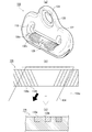
- FIG. 2 is a diagram illustrating in detail the through anchor 108 of FIG.
- FIG. 2A is a perspective view of the through anchor 108.
- the through anchor 108 is almost entirely covered with a resin film 122 typified by materials such as PA, POM, ABS, PP, and the like.
- a part of the insert fitting 126 inside the resin film 122 can be confirmed from the vicinity of the bolt hole 124 through which the bolt 120 (see FIG. 1) is passed.
- the insert fitting 126 is a metal plate formed by punching, for example, and has an upper portion formed with a bolt hole 124 and a lower portion formed with an insertion hole 118 through which the webbing 104 is inserted.
- the resin film 122 is molded and integrated with the insert fitting 126.
- the through anchor 108 has sliding portions (first sliding portion 130a and second sliding portion 130b) on the lower edge 128 of the insertion hole 118.
- the lower edge 128 and the sliding portions come into contact with and slide when the webbing 104 is used, such as when the webbing 104 (see FIG. 1) is pulled out from the retractor 106 and when the webbing 104 is wound around the retractor 106.
- FIG. 2C is a schematic XX cross-sectional view of FIG. As illustrated in FIG. 2C, in the present embodiment, the first sliding portion 130 a and the second sliding portion 130 b are alternately arranged at two positions from the center to both ends in the longitudinal direction of the insertion hole 118. Are arranged in multiple numbers.
- the first sliding portion 130 a and the second sliding portion 130 b have different friction coefficients with respect to the webbing 104.
- the first sliding portion 130 a is a portion that uses the resin film 122 of the through anchor 108, and the friction coefficient thereof is slightly large depending on the material of the resin film 122.
- the second sliding portion 130b has a smaller friction coefficient with respect to the webbing 104 than the first sliding portion 130a.
- the friction coefficient mentioned here includes any constant of a dynamic friction coefficient (further, a sliding friction coefficient or a rolling friction coefficient) and a static friction coefficient. Then, the friction coefficient between the first sliding part 130a and the second sliding part 130b is compared between the dynamic friction coefficients or between the static friction coefficients.
- a resin material containing titanium dioxide can be used as the material of the second sliding portion 130b.
- a fluororesin or a resin material containing molybdenum disulfide may be used as the material of the second sliding portion 130b.
- metal plating for example, nickel plating, copper plating, chrome plating, etc.
- FIG. 2B is a view of the lower edge 128 of FIG. 2A as viewed from above.
- the webbing 104 a is illustrated with phantom lines when the webbing 104 is pulled out from the retractor 106 or when the webbing 104 is wound around the retractor 106, that is, in a state where the webbing 104 is not worn by the passenger.
- the sliding direction of the webbing 104 in this unmounted state is a drawing and winding direction perpendicular to the longitudinal direction of the lower edge 128, which is exemplified by a white arrow.
- the webbing 104 attached to the occupant is illustrated by a solid line.
- the seating position of the occupant is in front of the vehicle relative to the through anchor 108, so that the webbing 104 from the through anchor 108 toward the occupant is in contact with the lower edge 128 at an angle. That is, the sliding direction of the webbing 104 in the mounted state is an oblique direction exemplified by a black arrow.
- the webbing 104 In a state where the webbing 104 is mounted, when a load is applied to the webbing 104 from an occupant or an unillustrated pretensioner or energy absorbing mechanism (EA mechanism) is activated in an emergency, the webbing 104 is suddenly pulled out from the retractor 106. . Then, for example, the webbing 104 slides and moves to the vehicle front end in the insertion hole 118, and jamming may occur. Therefore, in the present embodiment, the first sliding portions 130a and the second sliding portions 130b are alternately arranged on the lower edge 128 along the longitudinal direction thereof, in other words, along the width direction of the webbing 104.
- EA mechanism energy absorbing mechanism
- the first sliding portion 130a and the second sliding portion 130b are provided so as to extend obliquely on the lower edge 128 along the sliding direction of the webbing 104 when worn.
- the webbing 104 pulled out abruptly generates a strong frictional force with the lower edge 128.
- the webbing 104 is guided along the second sliding portion 130b having a low friction coefficient, so that the sliding direction It can be pulled out smoothly. If the webbing 104 tries to move in the width direction, a plurality of first sliding portions 130a having a high coefficient of friction are arranged and become resistance, and thus the movement is limited. Therefore, the webbing 104 does not shift to the end in the insertion hole 118, thereby preventing jamming.
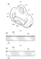
- FIG. 3 is a first modification of the through anchor 108 of FIG.
- the through anchor 200 also has a unique configuration so that jamming can be prevented.
- the lower edge 202 of the insertion hole 118 of the through anchor 200 of FIG. 3 is almost entirely over the first sliding portion 204a (see FIG. 3B). 2 is configured to be covered by the sliding portion 204b.
- the first sliding portion 204 a and the second sliding portion 204 b are portions having different friction coefficients (dynamic friction coefficient and static friction coefficient) with respect to the webbing 104.
- FIG. 3B is a schematic longitudinal sectional view in the longitudinal direction of the lower edge 202 of FIG. This sectional view corresponds to the AA section of FIG.
- the first sliding portion 204a is a portion using the resin film 122 of the through anchor 200, and the material thereof is composed of PA, POM, ABS, PP, or the like.
- the coefficient of friction with respect to the webbing 104 of the first sliding portion 204 a is slightly large depending on the material of the resin film 122.
- the second sliding portion 204b is provided as a thin film covering the first sliding portion 204a, which is made of a low friction material whose friction coefficient with respect to the webbing 104 is smaller than that of the first sliding portion 204a.
- the low friction material include a resin material containing titanium dioxide, a fluororesin, a resin material containing molybdenum disulfide, and metal plating. Since the second sliding portion 204b covers the first sliding portion 204a, the webbing 104 is in contact with only the second sliding portion 204b having a small coefficient of friction under normal use conditions, and can be smoothly pulled out. Winding is possible.
- FIG. 3B is a diagram illustrating a state in which the webbing 104 of FIG.
- the webbing 104 and the second slide are separated.
- a strong force is applied between the moving portion 204b and a frictional force or the like is generated.
- the second sliding portion 204b is scraped or removed by this large force, friction, or the like, and the first sliding portion 204a having a friction coefficient larger than that of the second sliding portion 204b is exposed. Therefore, the webbing 104a hardly moves in the insertion hole 118, and jamming is prevented from occurring.
- the through anchor 200 can prioritize the pull-out property of the webbing 104 during normal times, and can suppress jamming by suppressing the movement of the webbing 104 during an emergency.
- the pull-out property of the webbing 104 is not affected at all.
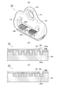
- FIG. 4 is a second modification of the through anchor 200 of FIG.
- the through anchor 300 is different in configuration from the above through anchors mainly in the shape of the first sliding portion 302.
- FIG. 4A is a perspective view of the through anchor 300.
- FIG. 4B is a schematic longitudinal sectional view in the longitudinal direction in the vicinity of the lower edge 302 of the through anchor 300 in FIG. This sectional view corresponds to the BB section in FIG.
- the first sliding part 304 is a part using the resin film 122 of the through anchor 300, and is provided with a large number of concave parts 304a and convex parts 304b. Further, the first sliding portion 304 has a friction coefficient that is slightly larger depending on the material of the resin film 122.
- the second sliding portion 204b is provided on the first sliding portion 304 as a thin film. The friction coefficient (dynamic friction coefficient or static friction coefficient) of the first sliding portion 304 is larger than that of the second sliding portion 204.
- the webbing 104 is normally in contact with the second sliding portion 204a and can be smoothly drawn out and wound up. 4C, when the webbing 104 is suddenly pulled out in an emergency, a large force is applied to the second sliding portion 204b, and the upper surface 305 of the convex portion 304b is caused by friction or the like. The second sliding portion 204b is scraped or removed, and the first sliding portion 304 whose friction coefficient (dynamic friction coefficient or static friction coefficient) with respect to the webbing 104 is higher than that of the second sliding portion 204b is exposed. Thereby, the movement of the webbing 104 is suppressed.
- friction coefficient dynamic friction coefficient or static friction coefficient
- the webbing 104 is prevented from moving in the width direction because the convex portions 304b interfere with each other. As a result, the webbing 104 is prevented from sliding to the end in the insertion hole 118 and offset, and jamming is prevented.
- the concave portion 304a and the convex portion 304b extend along the sliding direction of the webbing 104 when the occupant is mounted as described with reference to FIG. Is provided. Accordingly, the concave portion 304a and the convex portion 304b do not interfere with the movement of the webbing 104 in the sliding direction but interfere only when moving in the width direction. That is, it serves as a guide. With the configuration of the first sliding portion 304 and the second sliding portion 204b, the through anchor 300 can prioritize the pulling-out property of the webbing 104 in a normal state and can prevent jamming in an emergency.
- the present invention can be used for a seat belt device for restraining an occupant to a seat using webbing.
Landscapes
- Engineering & Computer Science (AREA)
- Mechanical Engineering (AREA)
- Automotive Seat Belt Assembly (AREA)
Description
本発明は、ウェビングを使用して乗員を座席に拘束するシートベルト装置に関するものである。
車両の座席にはシートベルト装置が設置されている。シートベルト装置は、車両に急停止や衝突などによって大きな減速度が作用した際に、慣性力による乗員の前方への飛出しを防ぐための安全装置である。シートベルト装置は、帯状のウェビングを利用して乗員を座席に拘束する。ウェビングは根元側が座席横に設置されたリトラクタに収納されていて、先端側がこのリトラクタから上方へ引き出されて車室内壁部のスルーアンカに通されている。そして、スルーアンカを通ったウェビングは下方へ折り返され、着脱用のタングプレートを通したうえでフロア付近のアンカプレートに固定されている。
現在のシートベルト装置には、その安全性能が落ちないよう様々な工夫がなされている。例えば、ウェビングが急激に引っ張られた際などに、ウェビングがスルーアンカの挿通孔内で横滑りして端に片寄ってしまう「ジャミング」と呼ばれる現象がある。このようなジャミングが起こると、ウェビングの引出性が低下してしまう。そこで、例えば特許文献1では、スルーアンカ(特許文献1内ではガイドアンカと称されている)の挿通孔内の下縁に、幾筋もの「突条」と呼ばれる凸形状の部位が設けられている。この突条はウェビングが強く引っ張られてスルーアンカが傾いた際などにウェビングの縁に接触する構成となっていて、これによってウェビングの幅方向の移動を阻んでジャミングを防止している。
上述したように、ジャミングは、緊急時においてウェビングが急激に引っ張られた場合、例えば、プリテンショナ(巻取装置)やエネルギ吸収機構(ウェビングによる急激な拘束を緩和する機構)が作動した場合などに起こり得る現象である。そのため、ジャミングの防止策は緊急時のみに発動し、通常時においてはウェビングを引き出す際の性能(引出性)になるべく影響を与えないような構成が望ましい。
本発明はこのような課題に鑑み、緊急時においてはジャミングの発生を防ぎ、通常時においてはウェビングの引出性に影響を与えないシートベルト装置を提供することを目的としている。
上記課題を解決するために、本発明にかかるシートベルト装置の代表的な構成は、車両の乗員を座席に拘束するシートベルト装置であって、帯状のウェビングと、車室内の壁部に取り付けられてウェビングが挿通されるスルーアンカと、を備え、スルーアンカは、ウェビングが挿通される挿通孔を有し、挿通孔の下縁は、ウェビングの使用時においてウェビングが接触し摺動する部分であり、下縁はさらに、ウェビングの幅方向に交互に並べられて、ウェビングに対してそれぞれ異なる摩擦係数を有する複数の摺動部を有することを特徴とする。
例えば、上記の摺動部のうちの一つとして、スルーアンカの下縁上にウェビングに対する摩擦係数の低い部位を複数設ける。その際、摺動部はウェビングの伸びる方向に沿って設ける。これによれば、ウェビングに、長手方向への引出性は阻害せず、幅方向への移動には抵抗を生じさせるなどの設定が可能になる。なお、上記の「摩擦係数」には動摩擦係数および静止摩擦係数のいずれの定数をも含む。そして、「摩擦係数が異なる」とは、動摩擦係数同士または静止摩擦係数同士で比較するとその値が異なっているという意味である。
上記の複数の摺動部は、第1摺動部と、第1摺動部よりもウェビングに対する摩擦係数が小さい第2摺動部とを含み、第1摺動部および第2摺動部はそれぞれ、下縁部上において、ウェビングの摺動方向に沿って伸びるよう設けられていてもよい。この構成によれば、ウェビングの引出性をより向上させることが可能になる。
上記課題を解決するために、本発明にかかるシートベルト装置の他の代表的な構成は、車両の乗員を座席に拘束するシートベルト装置であって、帯状のウェビングと、車室内の壁部に取り付けられてウェビングが挿通されるスルーアンカと、緊急時にウェビングを引き締めるプリテンショナと、を備え、スルーアンカは、ウェビングが挿通される挿通孔を有し、挿通孔の下縁は、ウェビングの使用時においてウェビングが摺動する、第1摺動部と、第1摺動部よりもウェビングに対する摩擦係数が小さい第2摺動部とを含み、第2摺動部は、第1摺動部上に設けられた被膜であって、プリテンショナの作動時におけるウェビングによって加えられる力により除去されて第1摺動部を露出させることを特徴とする。
上記のウェビングは、通常時においては、ウェビングに対する摩擦係数の小さい第2摺動部上を摺動する。そして、緊急時においては、第2摺動部が除去されてその下の摩擦係数の大きい第1摺動部を摺動する。すなわち、上記構成によれば、通常時にはウェビングの引出性を優先し、緊急時にはウェビングの横滑りを抑えてジャミングを防止することが可能になっている。なお、本願においてウェビングとの摩擦によって除去される事象には、ウェビングが摺動することにより削り取られる事象を含む。
上記課題を解決するために、本発明にかかるシートベルト装置の他の代表的な構成は、車両の乗員を座席に拘束するシートベルト装置であって、帯状のウェビングと、車室内の壁部に取り付けられてウェビングが挿通されるスルーアンカと、緊急時にウェビングの急激な拘束を緩和するエネルギ吸収機構と、を備え、スルーアンカは、ウェビングが挿通される挿通孔を有し、挿通孔の下縁は、ウェビングの使用時においてウェビングが摺動する、第1摺動部と、第1摺動部よりもウェビングに対する摩擦係数が小さい第2摺動部とを含み、第2摺動部は、第1摺動部上に設けられた被膜であって、エネルギ吸収機構の作動時におけるウェビングによって加えられる力により除去されて第1摺動部を露出させることを特徴とする。この構成によっても、ウェビングは、通常時においては摩擦系数の小さい第2摺動部上を摺動し、緊急時においては第2摺動部を除去してその下の摩擦係数の大きい大摺動部上を摺動することが可能になる。
上記の第1摺動部は、ウェビングの幅方向に沿って設置され、ウェビングの摺動方向へ伸びる複数の凹凸を有し、第2摺動部は、少なくとも第1摺動部の凸部の上端面の上に設けられていてもよい。この構成によれば、まず、複数の凹凸がウェビングの幅方向に並んでいることで、これが干渉するためにウェビングは幅方向への移動が制限される。そして、これら凹凸は摺動方向へ伸びているため、ウェビングのガイドとなってその引出性を向上させることができる。さらには、これら凹凸、特に凸部の上端面に第2摺動部の被膜を形成しておくと、ウェビングの引出性をより向上させることができる。
上記の第2摺動部は、二酸化チタンを含んでいてもよい。その他、フッ素樹脂または二硫化モリブデン、またさらには金属メッキ(例えばニッケルメッキ、銅メッキ、クロムメッキ等)を含んでいてもよく、これらの構成によって、ウェビングに対する摩擦係数の小さい第2摺動部を好適に実現することが可能になる。
本発明によれば、緊急時においてはジャミングの発生を防ぎ、通常時においてはウェビングの引出性に影響を与えないシートベルト装置を提供可能である。
100 …シートベルト装置、102 …座席、104 …ウェビング、104a …通常時のウェビング、106 …リトラクタ、108 …スルーアンカ、110 …アンカプレート、112 …タングプレート、114 …バックル、116 …センタピラー、118 …挿通孔、120 …ボルト、122 …樹脂皮膜、126 …インサート金具、128 …挿通孔の下縁、130a …第1摺動部、130b …第2摺動部、200 …第1変形例のスルーアンカ、202 …挿通孔の下縁、204a …第1摺動部、204b …第2摺動部、300 …第2変形例のスルーアンカ、302 …下縁、304 …第1摺動部、304a …凹部、304b …凸部、305 …上端面
以下に添付図面を参照しながら、本発明の好適な実施形態について詳細に説明する。かかる実施形態に示す寸法、材料、その他具体的な数値などは、発明の理解を容易とするための例示に過ぎず、特に断る場合を除き、本発明を限定するものではない。なお、本明細書及び図面において、実質的に同一の機能、構成を有する要素については、同一の符号を付することにより重複説明を省略し、また本発明に直接関係のない要素は図示を省略する。
図1は、本発明の実施形態にかかるシートベルト装置100を例示した図である。図1に例示しているように、シートベルト装置100は、座席102に備えられた安全装置であって、帯状のウェビング104を使用して乗員を座席102に拘束する。なお、シートベルト装置100は、車両緊急時にウェビング104を急速に巻き取るプリテンショナ(図示省略)を備えている。また、ウェビング104の急激な拘束を緩和するエネルギ吸収機構(EA機構)も必要に応じて備える。
ウェビング104は、根元側がリトラクタ106に巻き取られていて、先端側は上方のスルーアンカ108を通って下方へ折り返されてアンカプレート110に固定されている。スルーアンカ108とアンカプレート110との間にはタングプレート112が備えられていて、このタングプレート112を乗員がバックル114に挿し込むことで装着状態となる。
スルーアンカ108は車室内の壁部の一部であるセンタピラー116に取り付けられている。スルーアンカ108には挿通孔118が設けられていて、この挿通孔118にウェビング104が通されている。スルーアンカ108はボルト120によってセンタピラー116に取り付けられていて、ボルト120を中心にして車両前後方向に回転するように動くことができる。
当該シートベルト装置100では、ジャミング(スルーアンカ108の挿通孔118内でウェビング104が片寄る現象)の発生が防止できるよう、スルーアンカ108を主として独自の構成が備えられている。
図2は、図1のスルーアンカ108を詳細に例示する図である。図2(a)は、スルーアンカ108の斜視図である。スルーアンカ108は、例えばPA、POM、ABS、PP等の材質に代表される樹脂皮膜122でほぼ全体が覆われている。スルーアンカ108のうち、ボルト120(図1参照)を通すボルト孔124の付近からは、樹脂皮膜122の内部のインサート金具126が一部確認できる。インサート金具126は、例えば打ち抜き加工により形成された金属板であり、上部にはボルト孔124が形成され、下部にはウェビング104を挿通する挿通孔118が形成されている。樹脂皮膜122は、このインサート金具126にモールド成形され、一体化している。
スルーアンカ108は、挿通孔118の下縁128に、摺動部(第1摺動部130aおよび第2摺動部130b)を有している。これら下縁128および各摺動部は、リトラクタ106からウェビング104(図1参照)を引き出す際、およびウェビング104がリトラクタ106に巻き取られる際など、ウェビング104の使用時にこれが接触して摺動する部分である。図2(c)は、図2(a)の概略的なX-X断面図である。図2(c)に例示するように、本実施形態では、第1摺動部130aおよび第2摺動部130bは、挿通孔118の長手方向における中央から両端かけての2箇所にて、交互に複数配列されている。
第1摺動部130aと第2摺動部130bは、ウェビング104に対してそれぞれ異なる摩擦係数を有している。まず、第1摺動部130aは、本実施形態ではスルーアンカ108の樹脂皮膜122を利用した部位であって、その摩擦係数は樹脂皮膜122の材質に応じて、やや大きいものとなっている。一方、第2摺動部130bは、第1摺動部130aに比べてウェビング104に対する摩擦係数が小さい構成となっている。なお、ここで言う摩擦係数には、動摩擦係数(さらにはすべり摩擦係数やころがり摩擦係数)および静止摩擦係数のいずれの定数をも含む。そして、第1摺動部130aと第2摺動部130bの摩擦係数の比較は、動摩擦係数同士または静止摩擦係数同士で行う。
第2摺動部130bの材質としては、二酸化チタンを含んだ樹脂材料を挙げることができる。その他にも、フッ素樹脂や、二硫化モリブデンを含んだ樹脂材料などでもよい。さらには、金属メッキ(例えば、ニッケルメッキ、銅メッキ、クロムメッキ等)を施すことでも実現可能である。なお、これら第1摺動部130aと第2摺動部130bは、二色成型によって同時に形成可能である。
図2(b)は、図2(a)の下縁128を上方から見た図である。図2(b)では、リトラクタ106からウェビング104を引き出す際、またはリトラクタ106にウェビング104が巻き取られる際の、すなわち乗員に装着されていない状態におけるウェビング104aを仮想線で例示している。この未装着状態におけるウェビング104の摺動方向は、白矢印にて例示する、下縁128の長手方向に直交した引出しおよび巻取り方向となる。
一方、乗員に装着された状態のウェビング104を実線で例示する。多くの場合、乗員の着座位置はスルーアンカ108よりも車両前方にあるため、スルーアンカ108から乗員に向かうウェビング104は、下縁128に対して斜めに接触する。すなわち、装着状態におけるウェビング104の摺動方向は、黒矢印にて例示する斜め方向となる。
ウェビング104の装着状態において、緊急時にウェビング104に乗員から荷重がかけられたり、または不図示のプリテンショナやエネルギ吸収機構(EA機構)が作動したりすると、ウェビング104は急激にリトラクタ106から引き出される。すると、例えばウェビング104は挿通孔118の内の車両前方側の端へと横滑りして移動してしまい、ジャミングが発生するおそれがある。そこで本実施形態では、下縁128にその長手方向に沿って、言い換えるとウェビング104の幅方向に沿って、第1摺動部130aおよび第2摺動部130bが交互になるよう並べている。
第1摺動部130aおよび第2摺動部130bは、装着時のウェビング104の摺動方向に沿って、下縁128上において斜めに伸びるよう設けられている。急激に引き出されたウェビング104は下縁128との間に強い摩擦力を生じさせるが、その際、摩擦係数の低い第2摺動部130bに沿うことでこれに案内されるため、摺動方向へと円滑に引き出すことが可能になっている。そして、ウェビング104が仮に幅方向へと移動しようとした場合は、摩擦係数の高い第1摺動部130aが複数並んでいてこれらが抵抗となるため、その移動が制限される。したがって、ウェビング104は挿通孔118内の端に片寄ることがなく、これによってジャミングの発生が防止される。
これらのように、本実施形態の構成によれば、ウェビング104の引出性を向上させつつ、ジャミングの発生を防止することができる。この構成であれば、緊急時以外の通常の使用状態においては、ウェビング104の引出性等になんら影響を与えることがないため、好適である。
(第1変形例)
図3は、図2のスルーアンカ108の第1変形例である。このスルーアンカ200もまた、ジャミングが防止できるよう、独自の構成を備えている。
図3は、図2のスルーアンカ108の第1変形例である。このスルーアンカ200もまた、ジャミングが防止できるよう、独自の構成を備えている。
図3のスルーアンカ200の挿通孔118の下縁202は、図2(a)の下縁128とは異なり、第1摺動部204a(図3(b)参照)の上のほぼ全面を第2摺動部204bが覆った構成となっている。これら第1摺動部204aおよび第2摺動部204bは、ウェビング104に対してそれぞれ異なる摩擦係数(動摩擦係数および静止摩擦係数)を有する部位である。
図3(b)は、図3(a)の下縁202の長手方向における概略的な縦断面図である。この断面図は、図3(a)のA-A断面に対応している。まず、第1摺動部204aは、スルーアンカ200の樹脂皮膜122を利用した部位であって、その材質はPA、POM、ABS、PP等で構成されている。第1摺動部204aのウェビング104に対する摩擦係数は、樹脂皮膜122の材質に応じて、やや大きいものとなっている。
一方、第2摺動部204bは、ウェビング104に対する摩擦係数が第1摺動部204aよりも小さい低摩擦材料で構成された、第1摺動部204aを覆う薄い被膜として設けられている。その低摩擦材料としては、二酸化チタンを含んだ樹脂材料、フッ素樹脂、二硫化モリブデンを含んだ樹脂材料、さらには金属メッキなどを例示することができる。この第2摺動部204bが第1摺動部204aを覆っていることで、ウェビング104は、通常の使用状況においては、摩擦係数の小さい第2摺動部204bのみに接し、円滑な引出しおよび巻取りが可能になっている。
図3(b)は、図3(a)のウェビング104が急激に引き出された状態を例示する図である。図3(b)に例示するように、緊急時において、ウェビング104に乗員から荷重がかけられたり、ウェビング104がプリテンショナまたはエネルギ吸収機構などによって急激に引き出されたりすると、ウェビング104と第2摺動部204bとの間に強い力が加わり、摩擦力等が生じる。すると、この大きな力や摩擦等によって第2摺動部204bは削り取られまたは除去され、第2摺動部204bよりも摩擦係数の大きい第1摺動部204aが露出する。したがって、ウェビング104aは挿通孔118内における移動が起こりにくくなり、ジャミングの発生が防止される。
以上のように、スルーアンカ200は、通常時にはウェビング104の引出性を優先し、緊急時にはウェビング104の移動を抑えてジャミングを防止することが可能になっている。特に、緊急時において初めて第1摺動部204aが露出するため、通常においてはウェビング104の引出性になんら影響を与えることがなく、好適である。
(第2変形例)
図4は、図2のスルーアンカ200の第2変形例である。このスルーアンカ300は、主に、第1摺動部302の形状の点において、前述の各スルーアンカと構成が異なっている。
図4は、図2のスルーアンカ200の第2変形例である。このスルーアンカ300は、主に、第1摺動部302の形状の点において、前述の各スルーアンカと構成が異なっている。
図4(a)はスルーアンカ300の斜視図である。このスルーアンカ300の挿通孔118の下縁302には、長手方向の中央から両端側にかけて、細かな凹凸が交互に並んでいる。図4(b)は、図4(a)のスルーアンカ300の下縁302付近における長手方向の概略的な縦断面図である。この断面図は、図4(a)のB-B断面に対応している。第1摺動部304は、スルーアンカ300の樹脂皮膜122を利用した部位であって、凹部304aおよび凸部304bが多数設けられている。また、この第1摺動部304は、その摩擦係数が樹脂皮膜122の材質に応じてやや大きいものとなっている。第2摺動部204bは、この第1摺動部304の上に、薄い被膜として設けられている。この第1摺動部304の摩擦係数(動摩擦係数または静止摩擦係数)は、第2摺動部204よりも大きい。
このスルーアンカ300の構成によっても、通常時には、ウェビング104は第2摺動部204aに接していて、円滑な引出しおよび巻取りが可能になっている。そして、図4(c)に例示するように、緊急時において、ウェビング104が急激に引き出されると、大きな力が第2摺動部204bに加わり、摩擦等によって凸部304bの上端面305の上にある第2摺動部204bは削り取られまたは除去され、ウェビング104に対する摩擦係数(動摩擦係数または静止摩擦係数)が第2摺動部204bよりも高い第1摺動部304が露出する。これによって、ウェビング104の移動が抑えられる。また、特に下縁302の長手方向、すなわちウェビング104の幅方向に凸部304bが並んでいることで、この凸部304bが干渉するためにウェビング104の幅方向への移動が防がれる。これらによって、挿通孔118内の端へウェビング104が横滑りして片寄ることが防がれ、ジャミングが防止される。
ここで、図4(a)に例示したように、凹部304aおよび凸部304bは、図2(b)を参照して説明した、乗員の装着時におけるウェビング104の摺動方向に沿って伸びるよう設けられている。従って、これら凹部304aおよび凸部304bは、ウェビング104の摺動方向への移動には干渉せずに幅方向への移動時のみに干渉する。すなわち、ガイドの役目をする。これら、第1摺動部304および第2摺動部204bの構成によって、スルーアンカ300は、通常時にはウェビング104の引出性を優先し、緊急時にはジャミングを防止することが可能になっている。
以上、添付図面を参照しながら本発明の好適な実施例について説明したが、以上に述べた実施形態は、本発明の好ましい例であって、これ以外の実施態様も、各種の方法で実施または遂行できる。特に本願明細書中に限定される主旨の記載がない限り、この発明は、添付図面に示した詳細な部品の形状、大きさ、および構成配置等に制約されるものではない。また、本願明細書の中に用いられた表現および用語は、説明を目的としたもので、特に限定される主旨の記載がない限り、それに限定されるものではない。
したがって、当業者であれば、特許請求の範囲に記載された範疇内において、各種の変更例または修正例に想到し得ることは明らかであり、それらについても当然に本発明の技術的範囲に属するものと了解される。
本発明は、ウェビングを使用して乗員を座席に拘束するシートベルト装置に利用することができる。
Claims (9)
- 車両の乗員を座席に拘束するシートベルト装置であって、
帯状のウェビングと、
車室内の壁部に取り付けられて前記ウェビングが挿通されるスルーアンカと、
を備え、
前記スルーアンカは、前記ウェビングが挿通される挿通孔を有し、
前記挿通孔の下縁は、前記ウェビングの使用時において該ウェビングが接触し摺動する部分であり、
前記下縁はさらに、前記ウェビングの幅方向に交互に並べられて、該ウェビングに対してそれぞれ異なる摩擦係数を有する複数の摺動部を有することを特徴とするシートベルト装置。 - 前記複数の摺動部は、第1摺動部と、該第1摺動部よりも前記ウェビングに対する摩擦係数が小さい第2摺動部とを含み、
前記第1摺動部および第2摺動部はそれぞれ、前記下縁部上において、前記ウェビングの摺動方向に沿って伸びるよう設けられていることを特徴とする請求項1に記載のシートベルト装置。 - 車両の乗員を座席に拘束するシートベルト装置であって、
帯状のウェビングと、
車室内の壁部に取り付けられて前記ウェビングが挿通されるスルーアンカと、
緊急時に前記ウェビングを引き締めるプリテンショナと、を備え、
前記スルーアンカは、前記ウェビングが挿通される挿通孔を有し、
前記挿通孔の下縁は、前記ウェビングの使用時において該ウェビングが摺動する、第1摺動部と、該第1摺動部よりも前記ウェビングに対する摩擦係数が小さい第2摺動部とを含み、
前記第2摺動部は、前記第1摺動部上に設けられた被膜であって、前記プリテンショナの作動時における前記ウェビングによって加えられる力により除去されて第1摺動部を露出させることを特徴とするシートベルト装置。 - 車両の乗員を座席に拘束するシートベルト装置であって、
帯状のウェビングと、
車室内の壁部に取り付けられて前記ウェビングが挿通されるスルーアンカと、
緊急時に前記ウェビングの急激な拘束を緩和するエネルギ吸収機構と、を備え、
前記スルーアンカは、前記ウェビングが挿通される挿通孔を有し、
前記挿通孔の下縁は、前記ウェビングの使用時において該ウェビングが摺動する、第1摺動部と、該第1摺動部よりも前記ウェビングに対する摩擦係数が小さい第2摺動部とを含み、
前記第2摺動部は、前記第1摺動部上に設けられた被膜であって、前記エネルギ吸収機構の作動時における前記ウェビングによって加えられる力により除去されて第1摺動部を露出させることを特徴とするシートベルト装置。 - 前記第1摺動部は、前記ウェビングの幅方向に沿って設置され、ウェビングの摺動方向へ伸びる複数の凹凸を有し、
前記第2摺動部は、少なくとも前記第1摺動部の凸部の上端面の上に設けられていることを特徴とする請求項3または4に記載のシートベルト装置。 - 前記第2摺動部は、二酸化チタンを含んでいることを特徴とする請求項3から5のいずれか1項に記載のシートベルト装置。
- 前記第2摺動部は、フッ素樹脂を含んでいることを特徴とする請求項3から5のいずれか1項に記載のシートベルト装置。
- 前記第2摺動部は、二硫化モリブデンを含んでいることを特徴とする請求項3から5のいずれか1項に記載のシートベルト装置。
- 前記第2摺動部は、金属メッキを含んでいることを特徴とする請求項3から5のいずれか1項に記載のシートベルト装置。
Priority Applications (1)
| Application Number | Priority Date | Filing Date | Title |
|---|---|---|---|
| JP2014534266A JP5829756B2 (ja) | 2012-09-06 | 2013-08-09 | シートベルト装置 |
Applications Claiming Priority (2)
| Application Number | Priority Date | Filing Date | Title |
|---|---|---|---|
| JP2012196382 | 2012-09-06 | ||
| JP2012-196382 | 2012-09-06 |
Publications (1)
| Publication Number | Publication Date |
|---|---|
| WO2014038355A1 true WO2014038355A1 (ja) | 2014-03-13 |
Family
ID=50236969
Family Applications (1)
| Application Number | Title | Priority Date | Filing Date |
|---|---|---|---|
| PCT/JP2013/071694 Ceased WO2014038355A1 (ja) | 2012-09-06 | 2013-08-09 | シートベルト装置 |
Country Status (2)
| Country | Link |
|---|---|
| JP (1) | JP5829756B2 (ja) |
| WO (1) | WO2014038355A1 (ja) |
Cited By (1)
| Publication number | Priority date | Publication date | Assignee | Title |
|---|---|---|---|---|
| FR3152262A1 (fr) | 2023-08-24 | 2025-02-28 | Psa Automobiles Sa | Dispositif de renvoi perfectionné pour ceintures de sécurité de véhicules automobiles |
Citations (3)
| Publication number | Priority date | Publication date | Assignee | Title |
|---|---|---|---|---|
| JP2002154403A (ja) * | 2000-11-22 | 2002-05-28 | Nsk Ltd | シートベルト装置 |
| JP2010069951A (ja) * | 2008-09-16 | 2010-04-02 | Enshu:Kk | シートベルト吊持具 |
| JP2010285125A (ja) * | 2009-06-15 | 2010-12-24 | Tokai Rika Co Ltd | スリップジョイント |
-
2013
- 2013-08-09 WO PCT/JP2013/071694 patent/WO2014038355A1/ja not_active Ceased
- 2013-08-09 JP JP2014534266A patent/JP5829756B2/ja active Active
Patent Citations (3)
| Publication number | Priority date | Publication date | Assignee | Title |
|---|---|---|---|---|
| JP2002154403A (ja) * | 2000-11-22 | 2002-05-28 | Nsk Ltd | シートベルト装置 |
| JP2010069951A (ja) * | 2008-09-16 | 2010-04-02 | Enshu:Kk | シートベルト吊持具 |
| JP2010285125A (ja) * | 2009-06-15 | 2010-12-24 | Tokai Rika Co Ltd | スリップジョイント |
Cited By (1)
| Publication number | Priority date | Publication date | Assignee | Title |
|---|---|---|---|---|
| FR3152262A1 (fr) | 2023-08-24 | 2025-02-28 | Psa Automobiles Sa | Dispositif de renvoi perfectionné pour ceintures de sécurité de véhicules automobiles |
Also Published As
| Publication number | Publication date |
|---|---|
| JP5829756B2 (ja) | 2015-12-09 |
| JPWO2014038355A1 (ja) | 2016-08-08 |
Similar Documents
| Publication | Publication Date | Title |
|---|---|---|
| JP5808093B2 (ja) | タングおよびこれを用いたシートベルト装置 | |
| US9988013B2 (en) | Grip tongue latch plate for seatbelt | |
| JP4925445B2 (ja) | ベルトガイドアンカーおよびこれを備えたシートベルト装置 | |
| JP5224827B2 (ja) | タングおよびこれを用いたシートベルト装置 | |
| EP2711251B1 (en) | Tongue and seatbelt device using same | |
| JP5845055B2 (ja) | スルーアンカ、スルーアンカの製造方法及びシートベルト装置 | |
| JP2004338477A (ja) | スルーアンカ | |
| JP5433693B2 (ja) | ウェビング挿通部材及びシートベルト装置 | |
| JP5829756B2 (ja) | シートベルト装置 | |
| EP2818368B1 (en) | Tongue and seatbelt device using same | |
| JP6009650B2 (ja) | シートベルト用スルーアンカおよびシートベルト装置 | |
| JP5797836B2 (ja) | シートベルト装置 | |
| JP5530148B2 (ja) | シートベルト装置 | |
| JP2007050824A (ja) | シートベルト用ガイドアンカーおよびこれを備えたシートベルト装置 | |
| JP2012096635A (ja) | シートベルト用スルーアンカ | |
| JP6138472B2 (ja) | シートベルト装置 | |
| JP6067361B2 (ja) | シートベルト装置 | |
| JP5726129B2 (ja) | シートベルト装置 | |
| JP2003019944A (ja) | シートベルト装置 | |
| JP2013230734A (ja) | シートベルト装置用タング及びシートベルト装置 | |
| JP2012224253A (ja) | 車両用シートベルトのタングプレート固定構造 | |
| JP2013032061A (ja) | シートベルト装置 | |
| JP5312244B2 (ja) | シートベルトガイドアンカーおよびこれを備えたシートベルト装置 | |
| JP2014051236A (ja) | シートベルト装置 | |
| KR20070040048A (ko) | 자동차 안전벨트 거치용 디-링 구조 |
Legal Events
| Date | Code | Title | Description |
|---|---|---|---|
| 121 | Ep: the epo has been informed by wipo that ep was designated in this application |
Ref document number: 13835191 Country of ref document: EP Kind code of ref document: A1 |
|
| ENP | Entry into the national phase |
Ref document number: 2014534266 Country of ref document: JP Kind code of ref document: A |
|
| NENP | Non-entry into the national phase |
Ref country code: DE |
|
| 122 | Ep: pct application non-entry in european phase |
Ref document number: 13835191 Country of ref document: EP Kind code of ref document: A1 |