WO2014038099A1 - 車両用のバッテリシステムとこれを搭載する車両 - Google Patents
車両用のバッテリシステムとこれを搭載する車両 Download PDFInfo
- Publication number
- WO2014038099A1 WO2014038099A1 PCT/JP2012/080908 JP2012080908W WO2014038099A1 WO 2014038099 A1 WO2014038099 A1 WO 2014038099A1 JP 2012080908 W JP2012080908 W JP 2012080908W WO 2014038099 A1 WO2014038099 A1 WO 2014038099A1
- Authority
- WO
- WIPO (PCT)
- Prior art keywords
- battery
- vehicle
- sub
- lead
- voltage
- Prior art date
- Legal status (The legal status is an assumption and is not a legal conclusion. Google has not performed a legal analysis and makes no representation as to the accuracy of the status listed.)
- Ceased
Links
Images

Classifications
-
- H—ELECTRICITY
- H02—GENERATION; CONVERSION OR DISTRIBUTION OF ELECTRIC POWER
- H02J—ELECTRIC POWER NETWORKS; CIRCUIT ARRANGEMENTS OR SYSTEMS FOR SUPPLYING OR DISTRIBUTING ELECTRIC POWER; SYSTEMS FOR STORING ELECTRIC ENERGY
- H02J7/00—Circuit arrangements for charging or discharging batteries or for supplying loads from batteries
- H02J7/50—Circuit arrangements for charging or discharging batteries or for supplying loads from batteries acting upon multiple batteries simultaneously or sequentially
- H02J7/52—Circuit arrangements for charging or discharging batteries or for supplying loads from batteries acting upon multiple batteries simultaneously or sequentially for charge balancing, e.g. equalisation of charge between batteries
-
- B—PERFORMING OPERATIONS; TRANSPORTING
- B60—VEHICLES IN GENERAL
- B60L—PROPULSION OF ELECTRICALLY-PROPELLED VEHICLES; SUPPLYING ELECTRIC POWER FOR AUXILIARY EQUIPMENT OF ELECTRICALLY-PROPELLED VEHICLES; ELECTRODYNAMIC BRAKE SYSTEMS FOR VEHICLES IN GENERAL; MAGNETIC SUSPENSION OR LEVITATION FOR VEHICLES; MONITORING OPERATING VARIABLES OF ELECTRICALLY-PROPELLED VEHICLES; ELECTRIC SAFETY DEVICES FOR ELECTRICALLY-PROPELLED VEHICLES
- B60L58/00—Methods or circuit arrangements for monitoring or controlling batteries or fuel cells, specially adapted for electric vehicles
- B60L58/10—Methods or circuit arrangements for monitoring or controlling batteries or fuel cells, specially adapted for electric vehicles for monitoring or controlling batteries
- B60L58/12—Methods or circuit arrangements for monitoring or controlling batteries or fuel cells, specially adapted for electric vehicles for monitoring or controlling batteries responding to state of charge [SoC]
- B60L58/13—Maintaining the SoC within a determined range
-
- B—PERFORMING OPERATIONS; TRANSPORTING
- B60—VEHICLES IN GENERAL
- B60L—PROPULSION OF ELECTRICALLY-PROPELLED VEHICLES; SUPPLYING ELECTRIC POWER FOR AUXILIARY EQUIPMENT OF ELECTRICALLY-PROPELLED VEHICLES; ELECTRODYNAMIC BRAKE SYSTEMS FOR VEHICLES IN GENERAL; MAGNETIC SUSPENSION OR LEVITATION FOR VEHICLES; MONITORING OPERATING VARIABLES OF ELECTRICALLY-PROPELLED VEHICLES; ELECTRIC SAFETY DEVICES FOR ELECTRICALLY-PROPELLED VEHICLES
- B60L58/00—Methods or circuit arrangements for monitoring or controlling batteries or fuel cells, specially adapted for electric vehicles
- B60L58/10—Methods or circuit arrangements for monitoring or controlling batteries or fuel cells, specially adapted for electric vehicles for monitoring or controlling batteries
- B60L58/12—Methods or circuit arrangements for monitoring or controlling batteries or fuel cells, specially adapted for electric vehicles for monitoring or controlling batteries responding to state of charge [SoC]
- B60L58/14—Preventing excessive discharging
-
- B—PERFORMING OPERATIONS; TRANSPORTING
- B60—VEHICLES IN GENERAL
- B60L—PROPULSION OF ELECTRICALLY-PROPELLED VEHICLES; SUPPLYING ELECTRIC POWER FOR AUXILIARY EQUIPMENT OF ELECTRICALLY-PROPELLED VEHICLES; ELECTRODYNAMIC BRAKE SYSTEMS FOR VEHICLES IN GENERAL; MAGNETIC SUSPENSION OR LEVITATION FOR VEHICLES; MONITORING OPERATING VARIABLES OF ELECTRICALLY-PROPELLED VEHICLES; ELECTRIC SAFETY DEVICES FOR ELECTRICALLY-PROPELLED VEHICLES
- B60L58/00—Methods or circuit arrangements for monitoring or controlling batteries or fuel cells, specially adapted for electric vehicles
- B60L58/10—Methods or circuit arrangements for monitoring or controlling batteries or fuel cells, specially adapted for electric vehicles for monitoring or controlling batteries
- B60L58/12—Methods or circuit arrangements for monitoring or controlling batteries or fuel cells, specially adapted for electric vehicles for monitoring or controlling batteries responding to state of charge [SoC]
- B60L58/15—Preventing overcharging
-
- B—PERFORMING OPERATIONS; TRANSPORTING
- B60—VEHICLES IN GENERAL
- B60L—PROPULSION OF ELECTRICALLY-PROPELLED VEHICLES; SUPPLYING ELECTRIC POWER FOR AUXILIARY EQUIPMENT OF ELECTRICALLY-PROPELLED VEHICLES; ELECTRODYNAMIC BRAKE SYSTEMS FOR VEHICLES IN GENERAL; MAGNETIC SUSPENSION OR LEVITATION FOR VEHICLES; MONITORING OPERATING VARIABLES OF ELECTRICALLY-PROPELLED VEHICLES; ELECTRIC SAFETY DEVICES FOR ELECTRICALLY-PROPELLED VEHICLES
- B60L58/00—Methods or circuit arrangements for monitoring or controlling batteries or fuel cells, specially adapted for electric vehicles
- B60L58/10—Methods or circuit arrangements for monitoring or controlling batteries or fuel cells, specially adapted for electric vehicles for monitoring or controlling batteries
- B60L58/18—Methods or circuit arrangements for monitoring or controlling batteries or fuel cells, specially adapted for electric vehicles for monitoring or controlling batteries of two or more battery modules
- B60L58/20—Methods or circuit arrangements for monitoring or controlling batteries or fuel cells, specially adapted for electric vehicles for monitoring or controlling batteries of two or more battery modules having different nominal voltages
-
- H—ELECTRICITY
- H02—GENERATION; CONVERSION OR DISTRIBUTION OF ELECTRIC POWER
- H02J—ELECTRIC POWER NETWORKS; CIRCUIT ARRANGEMENTS OR SYSTEMS FOR SUPPLYING OR DISTRIBUTING ELECTRIC POWER; SYSTEMS FOR STORING ELECTRIC ENERGY
- H02J7/00—Circuit arrangements for charging or discharging batteries or for supplying loads from batteries
- H02J7/875—Charging or discharging for charge maintenance, battery initiation or rejuvenation
-
- B—PERFORMING OPERATIONS; TRANSPORTING
- B60—VEHICLES IN GENERAL
- B60L—PROPULSION OF ELECTRICALLY-PROPELLED VEHICLES; SUPPLYING ELECTRIC POWER FOR AUXILIARY EQUIPMENT OF ELECTRICALLY-PROPELLED VEHICLES; ELECTRODYNAMIC BRAKE SYSTEMS FOR VEHICLES IN GENERAL; MAGNETIC SUSPENSION OR LEVITATION FOR VEHICLES; MONITORING OPERATING VARIABLES OF ELECTRICALLY-PROPELLED VEHICLES; ELECTRIC SAFETY DEVICES FOR ELECTRICALLY-PROPELLED VEHICLES
- B60L2240/00—Control parameters of input or output; Target parameters
- B60L2240/40—Drive Train control parameters
- B60L2240/54—Drive Train control parameters related to batteries
- B60L2240/547—Voltage
-
- H—ELECTRICITY
- H02—GENERATION; CONVERSION OR DISTRIBUTION OF ELECTRIC POWER
- H02J—ELECTRIC POWER NETWORKS; CIRCUIT ARRANGEMENTS OR SYSTEMS FOR SUPPLYING OR DISTRIBUTING ELECTRIC POWER; SYSTEMS FOR STORING ELECTRIC ENERGY
- H02J2105/00—Networks for supplying or distributing electric power characterised by their spatial reach or by the load
- H02J2105/30—Networks for supplying or distributing electric power characterised by their spatial reach or by the load the load networks being external to vehicles, i.e. exchanging power with vehicles
- H02J2105/33—Networks for supplying or distributing electric power characterised by their spatial reach or by the load the load networks being external to vehicles, i.e. exchanging power with vehicles exchanging power with road vehicles
- H02J2105/37—Networks for supplying or distributing electric power characterised by their spatial reach or by the load the load networks being external to vehicles, i.e. exchanging power with vehicles exchanging power with road vehicles exchanging power with electric vehicles [EV] or with hybrid electric vehicles [HEV]
-
- Y—GENERAL TAGGING OF NEW TECHNOLOGICAL DEVELOPMENTS; GENERAL TAGGING OF CROSS-SECTIONAL TECHNOLOGIES SPANNING OVER SEVERAL SECTIONS OF THE IPC; TECHNICAL SUBJECTS COVERED BY FORMER USPC CROSS-REFERENCE ART COLLECTIONS [XRACs] AND DIGESTS
- Y02—TECHNOLOGIES OR APPLICATIONS FOR MITIGATION OR ADAPTATION AGAINST CLIMATE CHANGE
- Y02T—CLIMATE CHANGE MITIGATION TECHNOLOGIES RELATED TO TRANSPORTATION
- Y02T10/00—Road transport of goods or passengers
- Y02T10/60—Other road transportation technologies with climate change mitigation effect
- Y02T10/70—Energy storage systems for electromobility, e.g. batteries
Definitions
- the present invention relates to a vehicle battery system in which a sub-battery is connected in parallel with a lead battery, and a vehicle equipped with this battery system.
- a conventional vehicle is equipped with a lead battery having a rated voltage of 12V as a battery for electrical equipment, and in a large vehicle, a battery having a rated voltage of 24V by connecting two 12V lead batteries in series. It is equipped with.
- the lead battery is charged by the alternator of the vehicle, and supplies power to the electrical equipment and starter motor of the vehicle.
- this lead battery has a small discharge resistance, it has a drawback that it is difficult to charge efficiently because the charge resistance is large.
- a sub-battery is connected via a DC / DC converter in parallel with a lead battery. Since this battery system connects sub-batteries in parallel via a DC / DC converter, there is a drawback that the circuit configuration is complicated and the component cost and manufacturing cost are high. In particular, when this battery system is mounted on an idling stop vehicle and both lead battery and sub-battery are charged with the power generated by regenerative braking, it is necessary to increase the current capacity of the DC / DC converter. There is a drawback that the component cost and the manufacturing cost of the DC / DC converter become remarkably expensive. This is because regenerative braking charges the battery system with a very large current of 100 A or more, although for a short time.
- a battery system in which the sub-battery is connected via a DC / DC converter has a drawback that it is difficult to efficiently charge the sub-battery with the power generated by regenerative braking. This is because the power loss of the DC / DC converter reduces the charging power of the sub-battery.
- a battery system for a vehicle in which a lead battery and a sub-battery are connected in parallel is mounted on a vehicle at an idling stop, and generated power in regenerative braking when the vehicle is braked with a brake, that is, regenerative generated power.
- the regenerative power generation cannot be efficiently charged to the sub-battery due to poor compatibility between the lead battery and the sub-battery. There are disadvantages that are not sufficient.
- the battery system charged with regenerative power is not always held at a constant voltage by an alternator driven by an engine as in a conventional vehicle, but is quickly charged with a very large current at the timing of regenerative braking, In the discharged state, the alternator does not maintain a constant voltage, so that the voltage of the lead battery greatly fluctuates, the deterioration thereof is severe, and the lifetime is extremely short.
- An important object of the present invention is to provide a battery system for a vehicle that can be efficiently charged with the generated electric power of the vehicle while supplying a power to be efficiently stored on the vehicle side, and a vehicle equipped with the same. It is to provide.
- Another important object of the present invention is to provide a battery system for a vehicle that can improve the compatibility between a lead battery and a sub-battery and can considerably extend the life of the lead battery, and a vehicle equipped with the battery system. is there.
- the vehicle battery system of the present invention is a vehicle battery system in which a sub-battery 2 is connected in parallel to a lead battery 1, and the open circuit voltage-discharge depth characteristic of the sub-battery 2 is set to the upper limit of the lead battery 1.
- the voltage is at a discharge depth that can be charged, and the lower limit voltage of the lead battery 1 is a discharge depth at which discharge is possible.
- the above battery system is characterized in that it has a simple circuit configuration and is efficiently charged with the generated electric power of the vehicle, and can also supply electric power to be efficiently stored on the vehicle side. That is, the above battery system can charge the open circuit voltage-discharge depth characteristics of the sub-battery as a discharge depth that can be charged when the lead battery is the upper limit voltage and the charge needs to be limited. This is because the lead battery is in a state where it can be discharged at a discharge depth that can be discharged at a voltage that requires a lower limit voltage to limit the discharge.
- a lead battery cannot be charged by connecting a sub-battery having a specific open circuit voltage-depth of discharge characteristic in parallel with a lead battery having relatively little voltage fluctuation in the intermediate depth of discharge range. Even in the state, the sub-battery can be charged efficiently.
- the above characteristics are extremely important characteristics in an idling stop vehicle in which the engine is stopped when the vehicle is stopped by regenerative braking of the vehicle to charge the battery system. This is because the battery system is efficiently charged with the power generated by regenerative braking. In regenerative braking, the battery system is charged with an extremely large current within a short time within several tens of seconds of braking the vehicle, but the lead battery is extremely low in efficiency of large current charging, and the sub-battery is efficiently charged. In particular, in the battery system of the present invention, even when the voltage of the lead battery rises to the upper limit voltage and the charging current is limited, the discharge depth of the sub-battery is in a chargeable state, and regenerative braking power generation. It is charged with electricity efficiently.
- the above battery system realizes the effect of improving the fuel efficiency of the vehicle by generating power efficiently not only by regenerative braking but also by an alternator (alternator) driven by an engine.
- alternator alternator
- the engine has a characteristic that the fuel efficiency decreases at a light load close to idling. This is clear from the fact that the hybrid car is driven by a motor at a light load to improve fuel efficiency.
- the engine can increase the load, that is, increase the rotational torque of the alternator to improve fuel efficiency, and the alternator can increase the output and increase the power generation efficiency. Therefore, the fuel efficiency can be improved by increasing the output of the alternator and increasing the load of the engine that rotates the alternator.
- the lead battery has a characteristic that, for example, in a state where the output voltage is 14 V, the charging current does not increase and cannot be charged with a large current.
- the output voltage of the alternator is kept constant at 14V, the power of the sub battery is charged several times as much as the lead battery, so the output of the alternator is increased and the load on the engine is increased.
- the battery system can be charged efficiently in a short time. For this reason, even in a vehicle that does not regeneratively brake, the time for charging the battery system by driving the alternator with the engine is shortened, and the effect of improving the fuel efficiency of the vehicle is realized by increasing the short-time charging capacity. .
- the above battery system charges the sub battery at the upper limit voltage of the lead battery and allows the sub battery to be discharged even at the lower limit voltage, thereby preventing overcharge and over discharge of the lead battery and preventing deterioration. This also realizes a feature that can significantly extend the life of the lead battery.
- the depth of discharge of the sub-battery 2 at the upper limit voltage of the lead battery 1 may be 30% or more, and the depth of discharge of the sub-battery 2 at the lower limit voltage of the lead battery 1 may be 90% or less. it can.
- the vehicle battery system described above specifies the open circuit voltage-discharge depth characteristics of the sub battery so that the discharge depth of the sub battery falls within a specific range at the upper limit voltage and the lower limit voltage of the lead battery. Therefore, in the charged state of the battery system, even if the open circuit voltage of the lead battery rises to the upper limit voltage, the sub battery can be efficiently charged with the discharge depth of the sub battery being 30% or more. Further, in the discharged state, even if the open circuit voltage of the lead battery drops to the lower limit voltage, the sub battery can be discharged at a depth of discharge of 90% or less. Can be supplied to supply power to the electrical equipment such as a load on the vehicle side.
- a lead battery and a sub-battery having a specific open-circuit voltage-discharge depth characteristic are connected in parallel for extremely efficient charging / discharging.
- an idling stop vehicle has a feature that can significantly contribute to improving the fuel consumption of the vehicle because the battery system can be charged very efficiently with the power generated by regenerative braking.
- the upper limit voltage of the lead battery 1 can be set to 12.8 V at the open circuit voltage. Furthermore, the vehicle battery system of the present invention can set the lower limit voltage of the lead battery 1 to 12.4 V in the open circuit voltage.
- the upper limit voltage of the lead battery 1 is set to 12.8 V in the open circuit voltage
- the discharge depth of the sub battery 2 at this upper limit voltage is set to 30% or more
- the lower limit voltage of the lead battery 1 is set to the open circuit voltage.
- the depth of discharge of the sub-battery 2 at this lower limit voltage can be 90% or less.
- the battery system for a vehicle described above is configured so that the sub battery has a discharge depth within a specific range at an open circuit voltage of 12.8 V that is the upper limit voltage of the lead battery and an open circuit voltage of 12.4 V that is the lower limit voltage.
- the battery can be discharged to supply electric power such as an electrical equipment that is a load on the vehicle side. Therefore, in the above battery system, a lead battery and a sub-battery having a specific open-circuit voltage-discharge depth characteristic are connected in parallel for extremely efficient charging / discharging. There is a feature that can significantly improve the fuel economy. In particular, an idling stop vehicle has a feature that can significantly contribute to improving the fuel consumption of the vehicle because the battery system can be charged very efficiently with the power generated by regenerative braking.
- the lead battery 1 has a lower limit discharge depth for suppressing capacity deterioration, and the upper limit voltage of the lead battery 1 is set as an open circuit voltage in a fully charged state of the lead battery 1.
- the lower limit voltage of the lead battery 1 can be the open circuit voltage at the lower limit discharge depth of the lead battery 1.
- a lower limit discharge depth shall mean the lower limit of the depth of discharge for suppressing the capacity deterioration of a lead battery.
- the upper limit voltage of the lead battery is the open circuit voltage in the fully charged state of the lead battery, so it is effective that the lead battery is overcharged by charging the sub battery in the fully charged state of the lead battery. Can be prevented.
- the lower limit voltage of the lead battery is the open circuit voltage at the lower limit discharge depth of the lead battery, the sub battery can be discharged even at the lower limit voltage, thereby preventing the lead battery from over-discharging and preventing deterioration. . Therefore, it is possible to prevent the lead battery from being overcharged or overdischarged and to realize a feature that can significantly extend the life.
- the vehicle battery system of the present invention can connect the lead battery 1 and the sub battery 2 in parallel without using a voltage conversion circuit.
- the battery system described above is characterized in that the lead battery and the sub-battery are connected in parallel without using a voltage conversion circuit, so that the circuit configuration can be simplified and made inexpensive.
- the lead battery 1 and the sub battery 2 can be directly connected by the lead wire 4.
- the lead battery and the sub battery are directly connected to each other in parallel by connecting them with each other in parallel, so that it is possible to charge both the lead battery and the sub battery very efficiently while simplifying the circuit configuration.
- the sub-battery 2 can be a nickel-hydrogen battery 3.
- the battery system described above is characterized in that the sub-battery can be charged and discharged efficiently by adjusting the open circuit voltage-discharge depth characteristic to the optimum characteristic with the positive electrode material.
- the sub-battery 2 can connect ten nickel-metal hydride batteries 3 in series.
- the rated voltage of the lead battery and the sub-battery can be set to 12 V. Therefore, the lead battery and the sub-battery are balanced, and the open-circuit voltage-discharge depth characteristic of the sub-battery is made the optimum characteristic. And sub-battery can be charged and discharged efficiently.
- the sub-battery 2 can be a non-aqueous electrolyte secondary battery.
- the above battery system has a feature that the battery capacity (Ah) relative to the volume and weight of the sub-battery can be considerably increased as compared with the lead battery. Further, since the sub-battery is a non-aqueous electrolyte secondary battery, a feature that the sub-battery can be efficiently charged with a large amount of generated power is also realized.
- the battery system for a vehicle uses both the lead battery 1 and the sub battery 2 as a battery mounted on an idling stop vehicle, and charges both the lead battery 1 and the sub battery 2 with electric power of regenerative power generation of the vehicle. be able to.
- the above-described vehicle battery system is characterized by being efficiently charged with the power generated by regenerative braking and improving the fuel efficiency of the vehicle on which it is mounted. This is because the fuel system is charged efficiently, so that the engine consumes less fuel to charge it.
- the battery system mounted on the idling stop vehicle described above has a regenerative capacity sufficient for the sub-battery when the alternator is driven to generate power by setting the discharge depth of the sub-battery to 30% or more when the upper limit voltage of the lead battery is used. Can be secured.
- the discharge depth of the sub-battery is set to 90% or less at the lower limit voltage of the lead battery, even if the battery voltage decreases during idling stop, power is supplied from the sub-battery to the electrical components, and the voltage of the lead battery Since the decrease can be suppressed, the power generation drive time of the alternator can be shortened to further improve the vehicle fuel consumption performance.
- the battery capacity (Ah) of the sub-battery 2 can be made smaller than the battery capacity (Ah) of the lead battery 1. Since the above battery system uses a small-capacity battery for the sub-battery, the total cost can be reduced. In particular, using a nickel metal hydride battery or a non-aqueous electrolyte secondary battery that is more expensive than a lead battery for the sub-battery, there is a feature that the total cost can be reduced while realizing excellent charge / discharge characteristics.
- the battery capacity (Ah) of the sub-battery 2 can be set to 1/30 or more and 1/2 or less of the battery capacity (Ah) of the lead battery 1.
- a vehicle according to the present invention is a vehicle having an idling stop function including an engine for running the vehicle, an alternator driven by the engine, and a battery system charged by the alternator, and the battery system is any of the above. Is provided. Since the above vehicle can charge the battery system with a large current by the alternator, it is effective in improving the fuel efficiency of the vehicle. This is because the alternator can be operated in a region where the power generation efficiency is high, and the engine can also be operated in a region where the fuel consumption rate is small.
- a vehicle according to the present invention is a vehicle having an idling stop function including an engine for running the vehicle, an alternator driven by the engine and driven by regenerative braking of the vehicle, and a battery system charged by the alternator.
- the battery system has a configuration described in any of the above.
- the above-described vehicle has a feature that the fuel efficiency of the vehicle can be considerably improved by efficiently charging the battery system with the power generated by regenerative braking.
- the vehicle battery system shown in FIG. 1 has a lead battery 1 and a sub-battery 2 connected in parallel.
- the lead battery 1 and the sub-battery 2 are directly connected by the lead wire 4 without going through a current adjustment circuit or the like. Therefore, the voltage of the lead battery 1 and the sub battery 2 is always the same voltage.
- the lead battery and the sub-battery can be connected in parallel via a switching element such as a relay or a semiconductor switching element, and can also be connected in parallel via a diode or the like.
- the lead battery 1 is a battery in which 6 cells are connected in series and the rated voltage is 12V. However, the present invention does not specify the rated voltage of the lead battery as 12V. Two lead batteries can be connected in series for a rated voltage of 24V, three lead batteries can be connected in series for 36V, and four lead batteries can be connected in series for 48V. Because. Conventional electrical equipment is designed to operate with a power supply voltage of 12V, but vehicles equipped with lead batteries of 24V to 48V are equipped with electrical equipment that operates with this voltage.
- the sub-battery 2 is a nickel metal hydride battery 3.
- a sub-battery 2 formed by connecting ten nickel metal hydride batteries 3 in series is connected in parallel to a lead battery 1 having a power supply voltage of 12V. Since the nickel metal hydride battery 3 has a power supply voltage of 1.2 V, it is matched with the lead battery 1 by the number connected in series.
- all other secondary batteries such as a lithium ion secondary battery and a lithium polymer secondary battery can be used in place of the nickel metal hydride battery.
- the sub-battery 2 is connected in parallel in order to improve the charging / discharging efficiency and prevent the deterioration of the lead battery 1.
- the sub battery 2 is connected in parallel with the lead battery 1 and has the same voltage. In this state, the current balance of charging / discharging between the sub-battery 2 and the lead battery 1, that is, compatibility is important. If the compatibility is poor, only the lead battery and sub-battery will be charged, or only the lead battery and sub-battery will be discharged, so even if both are connected in parallel, the charge / discharge efficiency cannot be improved. The life of the lead battery cannot be effectively extended.
- the compatibility of the lead battery 1 and the sub battery 2 is realized by controlling the open circuit voltage-discharge depth characteristic of the sub battery 2.
- the open circuit voltage-discharge depth characteristics of the sub-battery 2 can be adjusted by, for example, the amount of zinc of the positive electrode in the nickel metal hydride battery 3, and the lithium-containing secondary battery or lithium polymer battery contains lithium as the positive electrode active material. It can be adjusted by selecting the compound.
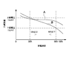
- FIG. 2 shows an open circuit voltage-discharge depth characteristic of the nickel metal hydride battery 3 of the sub-battery 2.
- a characteristic curve A shows an open-circuit voltage-discharge depth characteristic of a general nickel-metal hydride battery
- a characteristic curve B shows an open-circuit voltage-discharge of the nickel-metal hydride battery 3 adjusted to a characteristic suitable for the lead battery 1.
- Depth characteristics are shown.
- This figure shows the open circuit voltage with respect to the depth of discharge.
- the sub-battery 2 having the open circuit voltage-discharge depth characteristic of the characteristic curve B has a discharge depth that can be charged at the upper limit voltage of the lead battery 1 (open circuit voltage 12.8V), preferably 30% or more.
- the depth of discharge of the lead battery is specified by the upper limit voltage and the lower limit voltage, but it goes without saying that the lead battery can be charged and discharged beyond the upper limit voltage and the lower limit voltage.
- the upper limit voltage in this specification is an open circuit voltage that the lead battery is almost fully charged
- the lower limit voltage is a capacity deterioration (softening phenomenon) due to a decrease in bonding force between the positive electrode active material particles of the lead battery. It is an open circuit voltage at a predetermined discharge depth for suppression, and 12.8V is not necessarily an upper limit voltage and 12.4V is not necessarily a lower limit voltage.
- the lower limit of the discharge depth for suppressing the capacity deterioration of the lead battery is the lower limit discharge depth
- the open circuit voltage at the lower limit discharge depth is the lower limit voltage.
- the lead battery can suppress capacity deterioration of the lead battery by controlling charging / discharging of the lead battery so that the open circuit voltage does not fall below the lower limit voltage.
- a control unit on the vehicle side controls charging / discharging of the lead battery based on open circuit voltage data of the lead battery.
- the battery system for vehicles connects the following lead battery 1 and the nickel metal hydride battery 3 of the sub battery 2 in parallel.
- Lead battery 1 As the lead battery 1, a battery satisfying the following performance is used under the test conditions defined by the Battery Industry Association Standard (SBA S 0101). 5 hour rate capacity: 48Ah Rated cold cranking current: 320A Charge acceptance: 6.0A
- the sub battery 2 has ten nickel metal hydride batteries 3 connected in series.
- the nickel metal hydride battery 3 includes an electrode group consisting of a nickel positive electrode using nickel hydroxide as a main positive electrode active material, a hydrogen storage alloy negative electrode using a hydrogen storage alloy as a negative electrode active material, and a separator in an outer can together with an alkaline electrolyte. And use a battery with a capacity of 6.0 Ah.
- the nickel metal hydride battery 3 controls the amount of zinc and the amount of yttrium in the positive electrode in order to adjust the open circuit voltage-discharge depth characteristics.
- the lead battery 1 and the nickel metal hydride battery 3 are adjusted to the following state, and then connected in parallel with the lead wire 4 to form a battery system.
- the lead battery 1 has a charging condition defined by the Battery Industry Association Standard (SBA S 0101), that is, a terminal voltage during charging measured every 15 minutes under a charging current of 0.2 It, or an electrolyte density converted to temperature of 3 The battery is charged continuously until it shows a constant value, and the open circuit voltage after standing at room temperature for 24 hours is measured.
- SBA S 0101 Battery Industry Association Standard
- the nickel metal hydride battery 3 of the sub-battery 2 is charged to 110% of the battery capacity with a charging current of 1 It, then discharges a predetermined capacity at 1 It, and the open circuit voltage after standing at room temperature for 24 hours is the open circuit voltage of the lead battery 1. After confirming that the voltage is within 0.1 V, the lead battery 1 is connected in parallel.
- the relationship between the discharge depth of the sub-battery 2 and the open circuit voltage is measured as follows. After charging the nickel metal hydride battery 3 of the sub-battery 2 to 110% of the battery capacity with a charging current of 1 It, the predetermined capacity is discharged at 1 It, and the open circuit voltage after being left at room temperature for 24 hours is measured. The depth of discharge when the open circuit voltage indicates the upper limit voltage (open circuit voltage 12.8V) and the lower limit voltage (open circuit voltage 12.4V) of the lead battery 1 is calculated from the discharged capacity.
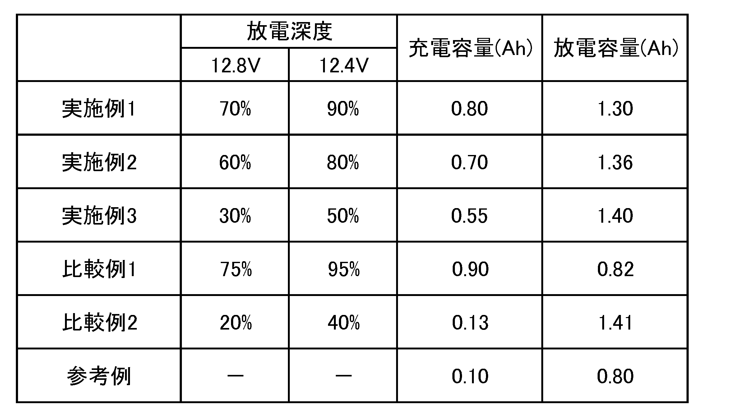
- Three types of nickel metal hydride batteries having different discharge depths with respect to the open circuit voltage were manufactured as shown in Table 1. Examples 1, 2, 3 having different open circuit voltage-discharge depth characteristics of the sub-batteries, that is, different discharge depths with respect to the open circuit voltage Prototype battery system.
- the nickel metal hydride battery of the sub-battery used in the battery system of Example 1 has a discharge depth at the upper limit voltage (12.8V) of the lead battery of 70%, and a discharge depth at the lower limit voltage (12.4V) of the lead battery.
- the open circuit voltage vs. depth of discharge characteristics are adjusted.
- the nickel metal hydride battery of the sub-battery used in the battery system of Example 2 has a discharge depth of 60% at the upper limit voltage (12.8V) of the lead battery, and a discharge depth of 80% at the lower limit voltage (12.4V) of the lead battery.
- the open circuit voltage vs. depth of discharge characteristics are adjusted.
- the nickel metal hydride battery of the sub-battery used in the battery system of Example 3 has a discharge depth of 30% at the upper limit voltage (12.8V) of the lead battery and 50% of the discharge depth at the lower limit voltage (12.4V) of the lead battery.
- the open circuit voltage vs. depth of discharge characteristics are adjusted.
- the sub-battery nickel metal hydride battery used in the battery system of Comparative Example 1 has a discharge depth of 75% at the upper limit voltage (12.8V) of the lead battery and a discharge depth of 95% at the lower limit voltage (12.4V) of the lead battery.
- the open circuit voltage vs. depth of discharge characteristics are adjusted.
- the sub-battery nickel metal hydride battery used in the battery system of Comparative Example 2 has a discharge depth of 20% at the upper limit voltage (12.8V) of the lead battery, and a discharge depth of 40% at the lower limit voltage (12.4V) of the lead battery.
- the open circuit voltage vs. depth of discharge characteristics are adjusted.
- the charging / discharging environment is set to a temperature of 25 ° C. ⁇ 2 ° C. and a wind speed of 2.0 m / s or less. Charging is performed at a charge voltage of 14.00 V ⁇ 0.03 V and a limiting current of 100.0 A ⁇ 0.5 A for 60.0 seconds ⁇ 0.3 seconds. The discharge is performed with a discharge current of 45A ⁇ 1A and is discharged until the lower limit voltage (open circuit voltage 12.4V) of the lead battery is reached.
- Table 1 also shows the charge capacity (Ah) and discharge capacity (Ah) of a lead battery alone without a sub-battery connected as a reference example.
- the lead battery alone has a charge capacity (Ah) of 0.10 (Ah) and a discharge capacity (Ah) of 0.80 (Ah).
- the charge capacity (Ah) is as large as 0.90 (Ah), but the discharge capacity (Ah) is 0.82 (Ah), which is almost the same as the lead battery alone. , Can not discharge efficiently.
- the battery system of Comparative Example 2 can increase the discharge capacity (Ah) to 1.41 (Ah), but the charge capacity (Ah) is 0.13 (Ah), which can hardly be increased from the lead battery alone.
- the discharge capacity (Ah) is 1.30 while the charge capacity (Ah) is 0.80 (Ah), which is eight times that of the lead battery alone. 60% increase from (Ah) and lead battery alone.
- the battery system of Example 2 has a charge capacity (Ah) of 0.70 (Ah), which is 7 times that of a lead battery alone, while a discharge capacity (Ah) of 1.36 (Ah), which is a lead battery. Increased by 70% from a single unit.
- the charge capacity (Ah) increases to 0.55 (Ah), which is 5.5 times that of the lead battery alone, while the discharge capacity (Ah) is 1.40 (Ah). And 75% increase from lead battery alone.
- the charging capacity (Ah) when charging with a large current of 100 A can be drastically improved from 5.5 to 8 times that of a lead battery alone, so that regenerative power generation in regenerative braking of a vehicle is possible. It can be recharged with electricity very efficiently. This is because the charging current of regenerative power is extremely large.
- the battery system of the present invention can store energy generated by regenerative braking extremely efficiently, and supplies the stored power to the electrical equipment 5 that is a load on the vehicle side much more efficiently than the lead battery alone. it can.
- the vehicle equipped with the battery system of the present invention realizes a feature that the fuel consumption efficiency can be considerably improved by significantly reducing the energy charged by driving the alternator 6 with the engine 7.
- the above battery system can improve fuel efficiency even in a vehicle that is charged by driving an alternator with an engine regardless of regenerative braking. This is because the sub-battery 2 can be charged up to eight times as much power as the lead battery 1.
- the alternator 6 of the vehicle stabilizes the output voltage to about 14 V, which is a constant voltage, in order to prevent the deterioration by charging the lead battery 1 with a constant voltage and to keep the supply voltage of the electrical equipment 5 constant. ing. Therefore, the current for the alternator 6 to charge the lead battery 1 is small and is not charged with a large current. Therefore, even if the alternator 6 having an output current of 100 A is mounted on the vehicle, the alternator 6 does not charge the lead battery 1 with 100 A. Has increased.
- the ability of the alternator 6 to charge the battery system with a large current is effective in improving the fuel efficiency of the vehicle. This is because the alternator 6 can be operated in a region where the power generation efficiency is high, and the engine 7 can also be operated in a region where the fuel consumption rate is small. This is because the alternator 6 has low power generation efficiency at light loads, and the engine 7 has a high fuel consumption rate at light loads.
- the vehicle battery system of the present invention protects the lead battery 1 from high-current charging by charging not only the lead battery 1 but also the sub-battery 2 with regenerative braking generated power, and is not charged by the alternator 6. In the state, power is supplied not only to the lead battery 1 but also from the charged sub-battery 2 to the electrical equipment 5, so that the lead battery 1 can be prevented from being charged and over-discharged, and the life can be remarkably increased.
- the sub-battery 2 is the nickel metal hydride battery 3, but the lithium ion secondary battery and the lithium polymer battery can also control the voltage-depth of discharge characteristics to the optimum value, Charging capacity (Ah) and discharging capacity (Ah) can be increased to improve regenerative braking and alternator charging efficiency and discharging efficiency.
- Charging capacity (Ah) and discharging capacity (Ah) can be increased to improve regenerative braking and alternator charging efficiency and discharging efficiency.
- charging efficiency and discharge efficiency can be improved by controlling the open circuit voltage-discharge depth characteristics within the optimum range.
- this battery system is also featured in that it can be mounted on a vehicle to improve fuel efficiency, and to prevent deterioration of the lead battery 1 to significantly improve the life characteristics.
- the battery system for a vehicle of the present invention is optimally used for an idling stop vehicle in which the battery system is charged by regenerative braking because it efficiently charges the generated power to improve the fuel efficiency of the vehicle.
Landscapes
- Engineering & Computer Science (AREA)
- Power Engineering (AREA)
- Life Sciences & Earth Sciences (AREA)
- Sustainable Development (AREA)
- Sustainable Energy (AREA)
- Transportation (AREA)
- Mechanical Engineering (AREA)
- Charge And Discharge Circuits For Batteries Or The Like (AREA)
- Secondary Cells (AREA)
- Control Of Vehicle Engines Or Engines For Specific Uses (AREA)
Abstract
【課題】簡単な回路構成としながら、車両の発電電力で効率よく充電され、また、車両側に効率よく蓄電する電力を供給する。 【解決手段】車両用のバッテリシステムは、鉛バッテリ1にサブバッテリ2を並列に接続している。このバッテリシステムは、サブバッテリ2の開路電圧-放電深度特性を、鉛バッテリ1の上限電圧においては充電可能な放電深度にあり、鉛バッテリ1の下限電圧においては放電可能な放電深度としている。
Description
本発明は、鉛バッテリと並列にサブバッテリを接続してなる車両用のバッテリシステムと、このバッテリシステムを搭載する車両に関する。
従来の車両は、電装用のバッテリとして、定格電圧を12Vとする鉛バッテリを搭載し、さらに、大型車両にあっては12Vの鉛バッテリを2組直列に接続して定格電圧を24Vとするバッテリを搭載している。鉛バッテリは、車両のオルタネータで充電されて、車両の電装器機やスターターモータなどに電力を供給している。この鉛バッテリは、放電抵抗は小さいが、充電抵抗が大きいので、効率よく充電するのが難しい欠点がある。この欠点を改善し、さらに容積や重量に対する電池容量(Ah)を大きくすることを目的として、鉛バッテリと並列にニッケル水素電池やリチウムイオン二次電池などを接続している車両用のバッテリシステムは開発されている。(特許文献1参照)
以上の車両用のバッテリシステムは、鉛バッテリと並列にDC/DCコンバータを介してサブバッテリを接続している。このバッテリシステムは、サブバッテリをDC/DCコンバータを介して並列に接続するので、回路構成が複雑で部品コストと製造コストとが高くなる欠点がある。とくに、このバッテリシステムがアイドリングストップの車両に搭載されて、回生制動の発電エネルギーで鉛バッテリとサブバッテリの両方を充電するとき、DC/DCコンバータの電流容量を極めて大きくする必要があって、DC/DCコンバータの部品コストと製造コストとが著しく高価になる欠点がある。回生制動は、短時間ではあるが、100A以上と極めて大きな電流でバッテリシステムを充電するからである。また、サブバッテリがDC/DCコンバータを介して接続されるバッテリシステムは、回生制動の発電電力で効率よくサブバッテリを充電するのが難しい欠点もある。それは、DC/DCコンバータの電力損失がサブバッテリの充電電力を減少させるからである。
さらに、鉛バッテリとサブバッテリとを並列に接続している車両用のバッテリシステムは、アイドリングストップの車両に搭載されて、車両をブレーキで制動するときの回生制動での発電電力、すなわち回生発電電力で充電しているが、鉛バッテリとサブバッテリとの間で、電圧と充電状態の適合性が悪いために、回生発電電力をサブバッテリに効率よく充電できず、回生制動による燃費効率の改善効果が充分でない欠点がある。さらに、回生発電電力で充電されるバッテリシステムは、従来の車両のように、エンジンで駆動されるオルタネータで常に一定の電圧には保持されず、回生制動するタイミングでは極めて大きな電流で急速充電され、放電される状態においては、オルタネータで一定の電圧に保持されないので、鉛バッテリの電圧が大幅に変動して、その劣化が甚だしく、寿命が極めて短くなる欠点がある。
本発明は、以上の欠点を解決することを目的に開発されたものである。本発明の重要な目的は、簡単な回路構成としながら、車両の発電電力で効率よく充電され、また、車両側に効率よく蓄電する電力を供給できる車両用のバッテリシステムとこれを搭載する車両を提供することにある。
また、本発明の他の大切な目的は鉛バッテリとサブバッテリとの適合性を改善して、鉛バッテリの寿命を相当に長くできる車両用のバッテリシステムとこれを搭載する車両を提供することにある。
また、本発明の他の大切な目的は鉛バッテリとサブバッテリとの適合性を改善して、鉛バッテリの寿命を相当に長くできる車両用のバッテリシステムとこれを搭載する車両を提供することにある。
本発明の車両用のバッテリシステムは、鉛バッテリ1にサブバッテリ2を並列に接続してなる車両用のバッテリシステムであって、サブバッテリ2の開路電圧-放電深度特性を、鉛バッテリ1の上限電圧においては充電可能な放電深度にあり、かつ鉛バッテリ1の下限電圧においては放電可能な放電深度としている。
以上のバッテリシステムは、簡単な回路構成としながら、車両の発電電力で効率よく充電され、また、車両側に効率よく蓄電する電力を供給できる特徴がある。それは、以上のバッテリシステムが、サブバッテリの開路電圧-放電深度特性を、鉛バッテリが上限電圧となって充電を制限する必要のある電圧においては充電可能な放電深度として充電できる状態とし、また、鉛バッテリが下限電圧となって放電を制限する必要のある電圧においては放電可能な放電深度として放電できる状態とするからである。以上の車両用のバッテリシステムは、中間の放電深度範囲においては比較的電圧変動の少ない鉛バッテリと並列に、特定の開路電圧-放電深度特性のサブバッテリを接続することによって、鉛バッテリを充電できない状態においてもサブバッテリを効率よく充電できる。
以上の特性は、車両を回生制動してバッテリシステムを充電して、車両を停止させる状態ではエンジンを停止させるアイドリングストップの車両において極めて大切な特性である。それは、回生制動の発電電力によって、バッテリシステムが効率よく充電されるからである。回生制動は、車両を制動する数十秒以内の短時間に、極めて大電流でバッテリシステムを充電するが、鉛バッテリは大電流充電の効率が極めて低く、サブバッテリには効率よく充電される。とくに、本発明のバッテリシステムは、鉛バッテリの電圧が上限電圧まで上昇して充電電流が制限される状態となっても、サブバッテリの放電深度は充電可能な状態にあって、回生制動の発電電力で効率よく充電される。
以上のバッテリシステムは、回生制動に限らず、エンジンで駆動されるオルタネータ(交流発電機)によっても効率よく発電して車両の燃費効率を改善できる効果を実現する。それは、エンジンの燃費効率を高く、かつオルタネータの発電効率をも高い状態としてバッテリシステムを充電できるからである。エンジンはアイドリングに近い軽い負荷においては燃費効率が低下する特性がある。このことは、ハイブリッドカーが軽い負荷ではモータで走行させて燃費効率を改善することからも明らかである。エンジンは、負荷を大きくして、すなわちオルタネータの回転トルクを大きくして燃費効率を向上でき、オルタネータは出力を大きくして発電効率を高くできる。したがって、オルタネータの出力を大きくして、これを回転させるエンジンの負荷を大きくして、燃費効率は改善できる。ただ、鉛バッテリは、例えば出力電圧を14Vとする状態では、充電電流が大きくならず、大電流で充電できない特性がある。ところが、以上のバッテリシステムは、オルタネータの出力電圧を14Vと一定にしながら、鉛バッテリの数倍もの電力がサブバッテリに充電されるので、オルタネータの出力を大きく、またエンジンの負荷を大きくして、短時間で効率よくバッテリシステムを充電できる。このため、回生制動しない車両においても、エンジンでオルタネータを駆動してバッテリシステムを充電する時間を短縮し、しかも、短時間の充電容量を大きくすることで車両の燃費効率を改善する効果を実現する。
さらに、以上のバッテリシステムは、鉛バッテリの上限電圧ではサブバッテリを充電し、下限電圧でもサブバッテリを放電できる状態とすることで、鉛バッテリの過充電や過放電を防止して劣化を防止し、これによって鉛バッテリの寿命を著しく長くできる特徴も実現する。
本発明の車両用のバッテリシステムは、鉛バッテリ1の上限電圧におけるサブバッテリ2の放電深度を30%以上として、鉛バッテリ1の下限電圧におけるサブバッテリ2の放電深度を90%以下とすることができる。
以上の車両用のバッテリシステムは、鉛バッテリの上限電圧と下限電圧において、サブバッテリの放電深度を特定の範囲とするようにサブバッテリの開路電圧-放電深度特性を特定する。したがって、バッテリシステムの充電状態においては、鉛バッテリの開路電圧が上限電圧まで上昇しても、サブバッテリの放電深度を30%以上としてサブバッテリを効率よく充電できる。また、放電状態においては、鉛バッテリの開路電圧が下限電圧まで低下しても、サブバッテリの放電深度を90%以下として放電できる状態とするので、鉛バッテリの放電が制限される状態ではサブバッテリを放電して車両側の負荷である電装器
機等の電力を供給できる。したがって、以上のバッテリシステムは、鉛バッテリと、特定の開路電圧-放電深度特性のサブバッテリを並列に接続することで、極めて効率よく充放電するので、バッテリシステムの充電電力を削減して、車両の燃費を相当に改善できる特徴がある。とくに、アイドリングストップの車両においては、回生制動の発電電力でバッテリシステムを極めて効率よく充電できるので、車両の燃費改善に相当に貢献できる特徴がある。
機等の電力を供給できる。したがって、以上のバッテリシステムは、鉛バッテリと、特定の開路電圧-放電深度特性のサブバッテリを並列に接続することで、極めて効率よく充放電するので、バッテリシステムの充電電力を削減して、車両の燃費を相当に改善できる特徴がある。とくに、アイドリングストップの車両においては、回生制動の発電電力でバッテリシステムを極めて効率よく充電できるので、車両の燃費改善に相当に貢献できる特徴がある。
本発明の車両用のバッテリシステムは、鉛バッテリ1の上限電圧を、開路電圧において12.8Vとすることができる。さらに、本発明の車両用のバッテリシステムは、鉛バッテリ1の下限電圧を、開路電圧において12.4Vとすることができる。
本発明の車両用のバッテリシステムは、鉛バッテリ1の上限電圧を開路電圧において12.8Vとし、この上限電圧におけるサブバッテリ2の放電深度を30%以上として、鉛バッテリ1の下限電圧を開路電圧において12.4Vとし、この下限電圧におけるサブバッテリ2の放電深度を90%以下とすることができる。
以上の車両用のバッテリシステムは、鉛バッテリの上限電圧である開路電圧12.8Vと、下限電圧である開路電圧12.4Vにおいて、サブバッテリの放電深度を特定の範囲とするようにサブバッテリの開路電圧-放電深度特性を特定する。したがって、バッテリシステムの充電状態においては、鉛バッテリの開路電圧が12.8Vまで上昇しても、サブバッテリの放電深度を30%以上としてサブバッテリを効率よく充電できる。また、放電状態においては、鉛バッテリの開路電圧が12.4Vまで低下しても、サブバッテリの放電深度を90%以下として放電できる状態とするので、鉛バッテリの放電が制限される状態ではサブバッテリを放電して車両側の負荷である電装器機等の電力を供給できる。したがって、以上のバッテリシステムは、鉛バッテリと、特定の開路電圧-放電深度特性のサブバッテリを並列に接続することで、極めて効率よく充放電するので、バッテリシステムの充電電力を削減して、車両の燃費を相当に改善できる特徴がある。とくに、アイドリングストップの車両においては、回生制動の発電電力でバッテリシステムを極めて効率よく充電できるので、車両の燃費改善に相当に貢献できる特徴がある。
本発明の車両用のバッテリシステムは、鉛バッテリ1が、容量劣化を抑制するための下限放電深度を有しており、鉛バッテリ1の上限電圧を、鉛バッテリ1の満充電状態における開路電圧とし、鉛バッテリ1の下限電圧を、鉛バッテリ1の下限放電深度における開路電圧とすることができる。
なお、本明細書において、下限放電深度とは、鉛バッテリの容量劣化を抑制するための放電深度の下限を意味するものとする。
以上のバッテリシステムは、鉛バッテリの上限電圧を、鉛バッテリの満充電状態における開路電圧とするので、鉛バッテリの満充電状態ではサブバッテリを充電することで鉛バッテリが過充電されるのを有効に防止できる。また、鉛バッテリの下限電圧を、鉛バッテリの下限放電深度における開路電圧とするので、下限電圧においてもサブバッテリを放電できる状態とすることで、鉛バッテリの過放電を防止して劣化を防止できる。したがって、鉛バッテリの過充電や過放電を防止して、寿命を著しく長くできる特徴を実現できる。
なお、本明細書において、下限放電深度とは、鉛バッテリの容量劣化を抑制するための放電深度の下限を意味するものとする。
以上のバッテリシステムは、鉛バッテリの上限電圧を、鉛バッテリの満充電状態における開路電圧とするので、鉛バッテリの満充電状態ではサブバッテリを充電することで鉛バッテリが過充電されるのを有効に防止できる。また、鉛バッテリの下限電圧を、鉛バッテリの下限放電深度における開路電圧とするので、下限電圧においてもサブバッテリを放電できる状態とすることで、鉛バッテリの過放電を防止して劣化を防止できる。したがって、鉛バッテリの過充電や過放電を防止して、寿命を著しく長くできる特徴を実現できる。
本発明の車両用のバッテリシステムは、鉛バッテリ1とサブバッテリ2とを電圧変換回路を介することなく並列に接続することができる。
以上のバッテリシステムは、電圧変換回路を使用することなく鉛バッテリとサブバッテリとを並列に接続するので、回路構成を簡単にして安価にできる特徴がある。
以上のバッテリシステムは、電圧変換回路を使用することなく鉛バッテリとサブバッテリとを並列に接続するので、回路構成を簡単にして安価にできる特徴がある。
本発明の車両用のバッテリシステムは、鉛バッテリ1とサブバッテリ2とをリード線4で直接に接続することができる。
以上のバッテリシステムは、鉛バッテリとサブバッテリとをリード線で直接に接続して互いに並列に接続するので、回路構成を最も簡単にしながら、鉛バッテリとサブバッテリの両方を極めて効率良く充電でき、また放電できる特徴がある。
以上のバッテリシステムは、鉛バッテリとサブバッテリとをリード線で直接に接続して互いに並列に接続するので、回路構成を最も簡単にしながら、鉛バッテリとサブバッテリの両方を極めて効率良く充電でき、また放電できる特徴がある。
本発明の車両用のバッテリシステムは、サブバッテリ2をニッケル水素電池3とすることができる。
以上のバッテリシステムは、正極の電極材料で開路電圧-放電深度特性を最適な特性に調整して、サブバッテリを効率よく充放電できる特徴がある。
以上のバッテリシステムは、正極の電極材料で開路電圧-放電深度特性を最適な特性に調整して、サブバッテリを効率よく充放電できる特徴がある。
本発明の車両用のバッテリシステムは、サブバッテリ2が10個のニッケル水素電池3を直列に接続することができる。
以上のバッテリシステムは、鉛バッテリとサブバッテリの定格電圧を12Vにできるので、鉛バッテリとサブバッテリとをバランスよく、しかもサブバッテリの開路電圧-放電深度特性を最適特性とすることで、鉛バッテリとサブバッテリの両方を効率よく充放電できる特徴がある。
以上のバッテリシステムは、鉛バッテリとサブバッテリの定格電圧を12Vにできるので、鉛バッテリとサブバッテリとをバランスよく、しかもサブバッテリの開路電圧-放電深度特性を最適特性とすることで、鉛バッテリとサブバッテリの両方を効率よく充放電できる特徴がある。
本発明の車両用のバッテリシステムは、サブバッテリ2を非水系電解液二次電池とすることができる。
以上のバッテリシステムは、サブバッテリの容積と重量に対する電池容量(Ah)を鉛バッテリに比較して相当に大きくできる特徴がある。また、サブバッテリを非水系電解液二次電池とするので、大電流の発電電力でサブバッテリを効率よく充電できる特徴も実現する。
以上のバッテリシステムは、サブバッテリの容積と重量に対する電池容量(Ah)を鉛バッテリに比較して相当に大きくできる特徴がある。また、サブバッテリを非水系電解液二次電池とするので、大電流の発電電力でサブバッテリを効率よく充電できる特徴も実現する。
本発明の車両用のバッテリシステムは、鉛バッテリ1とサブバッテリ2とを、アイドリングストップの車両に搭載されるバッテリとして、車両の回生発電の電力で鉛バッテリ1とサブバッテリ2の両方を充電することができる。
以上の車両用のバッテリシステムは、回生制動の発電電力で効率よく充電されて、これを搭載する車両の燃費を改善できる特徴がある。それは、バッテリシステムが効率よく充電される特徴によって、これを充電するためにエンジンが消費する燃料を少なくできるからである。とくに、以上のアイドリングストップの車両に搭載されるバッテリシステムは、鉛バッテリの上限電圧のとき、サブバッテリの放電深度を30%以上とすることで、オルタネータの発電駆動時にはサブバッテリに十分な回生容量を確保できる。また、鉛バッテリの下限電圧において、サブバッテリの放電深度を90%以下とすることで、アイドリングストップ中にバッテリ電圧が低下しても、サブバッテリから電装品に電力供給して、鉛バッテリの電圧低下を抑制できるので、オルタネータの発電駆動時間を短縮して、更なる車両燃費性能の改善が可能となる。
本発明の車両用のバッテリシステムは、サブバッテリ2の電池容量(Ah)を鉛バッテリ1の電池容量(Ah)よりも小さくすることができる。
以上のバッテリシステムは、サブバッテリに小容量のバッテリを使用するので、トータルコストを低減できる特徴がある。とくに、サブバッテリに鉛バッテリよりも高価なニッケル水素電池や非水系電解液二次電池を使用して、優れた充放電特性を実現しながら、トータルコストを低減できる特徴がある。
以上のバッテリシステムは、サブバッテリに小容量のバッテリを使用するので、トータルコストを低減できる特徴がある。とくに、サブバッテリに鉛バッテリよりも高価なニッケル水素電池や非水系電解液二次電池を使用して、優れた充放電特性を実現しながら、トータルコストを低減できる特徴がある。
本発明の車両用のバッテリシステムは、サブバッテリ2の電池容量(Ah)を鉛バッテリ1の電池容量(Ah)の1/30以上であって、1/2以下とすることができる。
本発明の車両は、車両を走行させるエンジンと、このエンジンで駆動されるオルタネータと、このオルタネータで充電されるバッテリシステムとを備えるアイドリングストップ機能の車両であって、バッテリシステムが、以上のいずれかに記載される構成を備えている。
以上の車両は、オルタネータによりバッテリシステムを大電流で充電できるので、車両の燃費効率を改善することに有効である。それは、オルタネータを高い発電効率の領域で運転し、かつエンジンも燃料消費率の小さい領域で運転できるからである。
以上の車両は、オルタネータによりバッテリシステムを大電流で充電できるので、車両の燃費効率を改善することに有効である。それは、オルタネータを高い発電効率の領域で運転し、かつエンジンも燃料消費率の小さい領域で運転できるからである。
本発明の車両は、車両を走行させるエンジンと、このエンジンで駆動され、かつ車両の回生制動で駆動されるオルタネータと、このオルタネータで充電されるバッテリシステムとを備えるアイドリングストップ機能の車両であって、バッテリシステムが、以上のいずれかに記載される構成を備えている。
以上の車両は、回生制動の発電電力でバッテリシステムを効率よく充電することで、車両の燃費を相当に改善できる特徴がある。
以上の車両は、回生制動の発電電力でバッテリシステムを効率よく充電することで、車両の燃費を相当に改善できる特徴がある。
以下、本発明の実施の形態を図面に基づいて説明する。ただし、以下に示す実施の形態は、本発明の技術思想を具体化するための車両用のバッテリシステムとこれを搭載する車両を例示するものであって、本発明は車両用のバッテリシステムとこれを搭載する車両を以下に特定しない。さらに、この明細書は、特許請求の範囲に示される部材を、実施の形態の部材に特定するものでは決してない。
図1に示す車両用のバッテリシステムは、鉛バッテリ1とサブバッテリ2とを並列に接続している。鉛バッテリ1とサブバッテリ2は、電流調整回路等を介することなく、リード線4で直接に接続される。したがって、鉛バッテリ1とサブバッテリ2の電圧は常に同じ電圧となる。ただし、本発明のバッテリシステムは、鉛バッテリとサブバッテリとをリレーや半導体スイッチング素子などのスイッチング素子を介して並列に接続し、ダイオード等を介して並列に接続することもできる。
鉛バッテリ1は、6セルを直列に接続して定格電圧を12Vとするバッテリである。ただ、本発明は鉛バッテリの定格電圧を12Vには特定しない。2個の鉛バッテリを直列に接続して定格電圧を24Vとし、また、3個の鉛バッテリを直列に接続して36V、4個の鉛バッテリを直列に接続して48Vとして使用することもできるからである。従来の電装器機は、12Vの電源電圧で動作するように設計されているが、24V~48Vの鉛バッテリを搭載する車両は、この電圧で動作する電装器機を搭載する。
サブバッテリ2は、ニッケル水素電池3である。電源電圧を12Vとする鉛バッテリ1には、10個のニッケル水素電池3を直列に接続してなるサブバッテリ2が並列に接続される。ニッケル水素電池3は電源電圧を1.2Vとするので、直列に接続する個数で鉛バッテリ1に整合させる。サブバッテリには、ニッケル水素電池に代わって、リチウムイオン二次電池、リチウムポリマー二次電池など、他の全ての二次電池も使用できる。
サブバッテリ2は、充放電の効率を改善し、かつ鉛バッテリ1の劣化を防止するために並列に接続される。サブバッテリ2は、鉛バッテリ1と並列に接続されて、同じ電圧となる。この状態において、サブバッテリ2と鉛バッテリ1との充放電の電流バランス、すなわち適合性が大切である。適合性が悪いと、鉛バッテリやサブバッテリのみが充電されたり、あるいは鉛バッテリやサブバッテリのみが放電されたりするため、両方を並列に接続しても、充放電の効率を改善できず、また鉛バッテリの寿命も効果的には長くできなくなる。
鉛バッテリ1とサブバッテリ2の適合性は、サブバッテリ2の開路電圧-放電深度特性をコントロールして実現する。サブバッテリ2の開路電圧-放電深度特性は、たとえば、ニッケル水素電池3においては正極の亜鉛量などで調整でき、リチウムイオン二次電池やリチウムポリマー電池にあっては、正極活物質であるリチウム含有化合物の選択により調整できる。図2は、サブバッテリ2のニッケル水素電池3の開路電圧-放電深度特性を示す。この図において、特性曲線Aは、一般的なニッケル水素電池の開路電圧-放電深度特性を示し、特性曲線Bは鉛バッテリ1に適合する特性に調整しているニッケル水素電池3の開路電圧-放電深度特性を示している。この図は、放電深度に対する開路電圧を示している。特性曲線Bの開路電圧-放電深度特性のサブバッテリ2は、鉛バッテリ1の上限電圧(開路電圧12.8V)において充電できる放電深度、好ましくは30%以上であって、鉛バッテリ1の下限電圧(開路電圧12.4V)において充電できる放電深度、好ましくは90%以下とする。以上のバッテリシステムは、鉛バッテリの放電深度を、上限電圧と下限電圧とで特定しているが、鉛バッテリは、上限電圧と下限電圧を越えて充放電することもできるのはいうまでもない。
なお、本明細書における上限電圧とは、鉛電池がほぼ満充電状態に示す開路電圧であり、下限電圧とは、鉛電池の正極活物質粒子間の結合力低下による容量劣化(軟化現象)を抑制するための、所定の放電深度における開路電圧であって、必ずしも12.8Vが上限電圧、12.4Vが下限電圧となるとは限らない。これらの値は、鉛バッテリの組成や、劣化をどの程度許容するかによって、適宜選択できる。なお、本明細書においては、鉛バッテリの容量劣化を抑制するための放電深度の下限を下限放電深度としており、この下限放電深度における開路電圧を下限電圧としている。鉛バッテリは、開路電圧が下限電圧を下回らないように鉛バッテリの充放電を制御することで、鉛バッテリの容量劣化を抑制することができる。例えば、車両に搭載される鉛バッテリの場合、車両側の制御部が鉛バッテリの開路電圧データに基づいて、鉛バッテリの充放電を制御するようになっている。
なお、本明細書における上限電圧とは、鉛電池がほぼ満充電状態に示す開路電圧であり、下限電圧とは、鉛電池の正極活物質粒子間の結合力低下による容量劣化(軟化現象)を抑制するための、所定の放電深度における開路電圧であって、必ずしも12.8Vが上限電圧、12.4Vが下限電圧となるとは限らない。これらの値は、鉛バッテリの組成や、劣化をどの程度許容するかによって、適宜選択できる。なお、本明細書においては、鉛バッテリの容量劣化を抑制するための放電深度の下限を下限放電深度としており、この下限放電深度における開路電圧を下限電圧としている。鉛バッテリは、開路電圧が下限電圧を下回らないように鉛バッテリの充放電を制御することで、鉛バッテリの容量劣化を抑制することができる。例えば、車両に搭載される鉛バッテリの場合、車両側の制御部が鉛バッテリの開路電圧データに基づいて、鉛バッテリの充放電を制御するようになっている。
[実施例1~3、及び比較例1、2のバッテリシステム]
車両用のバッテリシステムは、以下の鉛バッテリ1とサブバッテリ2のニッケル水素電池3とを並列に接続している。
車両用のバッテリシステムは、以下の鉛バッテリ1とサブバッテリ2のニッケル水素電池3とを並列に接続している。
(鉛バッテリ1)
鉛バッテリ1には、電池工業会規格(SBA S 0101)で定める試験条件で、以下の性能を満たすバッテリを使用する。
5時間率容量 :48Ah
定格コールドクランキング電流:320A
充電受入性 :6.0A
鉛バッテリ1には、電池工業会規格(SBA S 0101)で定める試験条件で、以下の性能を満たすバッテリを使用する。
5時間率容量 :48Ah
定格コールドクランキング電流:320A
充電受入性 :6.0A
(サブバッテリ2)
サブバッテリ2は、10個のニッケル水素電池3を直列に接続している。ニッケル水素電池3は、水酸化ニッケルを主正極活物質とするニッケル正極と、水素吸蔵合金を負極活物質とする水素吸蔵合金負極とセパレータとからなる電極群を、アルカリ電解液と共に外装缶内に入れて、容量を6.0Ahとする電池を使用する。このニッケル水素電池3は、開路電圧-放電深度特性を調整するために、正極の亜鉛量とイットリウム量をコントロールしている。
サブバッテリ2は、10個のニッケル水素電池3を直列に接続している。ニッケル水素電池3は、水酸化ニッケルを主正極活物質とするニッケル正極と、水素吸蔵合金を負極活物質とする水素吸蔵合金負極とセパレータとからなる電極群を、アルカリ電解液と共に外装缶内に入れて、容量を6.0Ahとする電池を使用する。このニッケル水素電池3は、開路電圧-放電深度特性を調整するために、正極の亜鉛量とイットリウム量をコントロールしている。
鉛バッテリ1とニッケル水素電池3とは、以下の状態に調整した後、リード線4で並列に接続してバッテリシステムとする。
鉛バッテリ1は、電池工業会規格(SBA S 0101)で定める充電条件、すなわち、0.2Itの充電電流で、15分ごとに測定した充電中の端子電圧、または温度換算した電解液密度が3回連続して一定値を示すまで充電し、常温24時間放置後の開路電圧を測定する。
サブバッテリ2のニッケル水素電池3は、1Itの充電電流で電池容量の110%まで充電した後、1Itで所定容量を放電し、常温24時間放置後の開路電圧が、鉛バッテリ1の開路電圧と0.1V以内であることを確認して鉛バッテリ1と並列に接続する。
サブバッテリ2の放電深度と開路電圧の関係は、以下のようにして測定する。
サブバッテリ2のニッケル水素電池3を1Itの充電電流で電池容量の110%まで充電した後、1Itで所定容量を放電し、常温で24時間放置後の開路電圧を測定する。この開路電圧が、鉛バッテリ1の上限電圧(開路電圧12.8V)と下限電圧(開路電圧12.4V)を示すときの放電深度を放電された容量から算出する。開路電圧に対する放電深度が異なる3種のニッケル水素電池を試作して、表1に示すように、サブバッテリの開路電圧-放電深度特性、すなわち開路電圧に対する放電深度が異なる実施例1、2、3のバッテリシステムを試作する。
サブバッテリ2のニッケル水素電池3を1Itの充電電流で電池容量の110%まで充電した後、1Itで所定容量を放電し、常温で24時間放置後の開路電圧を測定する。この開路電圧が、鉛バッテリ1の上限電圧(開路電圧12.8V)と下限電圧(開路電圧12.4V)を示すときの放電深度を放電された容量から算出する。開路電圧に対する放電深度が異なる3種のニッケル水素電池を試作して、表1に示すように、サブバッテリの開路電圧-放電深度特性、すなわち開路電圧に対する放電深度が異なる実施例1、2、3のバッテリシステムを試作する。
実施例1のバッテリシステムに使用するサブバッテリのニッケル水素電池は、鉛バッテリの上限電圧(12.8V)における放電深度を70%、鉛バッテリの下限電圧(12.4V)における放電深度を90%とする開路電圧-放電深度特性に調整している。
実施例2のバッテリシステムに使用するサブバッテリのニッケル水素電池は、鉛バッテリの上限電圧(12.8V)における放電深度を60%、鉛バッテリの下限電圧(12.4V)における放電深度を80%とする開路電圧-放電深度特性に調整している。
実施例3のバッテリシステムに使用するサブバッテリのニッケル水素電池は、鉛バッテリの上限電圧(12.8V)における放電深度を30%、鉛バッテリの下限電圧(12.4V)における放電深度を50%とする開路電圧-放電深度特性に調整している。
比較のために、開路電圧に対する放電深度が異なるニッケル水素電池を試作して、比較例1、2のバッテリシステムを試作する。
比較例1のバッテリシステムに使用するサブバッテリのニッケル水素電池は、鉛バッテリの上限電圧(12.8V)における放電深度を75%、鉛バッテリの下限電圧(12.4V)における放電深度を95%とする開路電圧-放電深度特性に調整している。
比較例2のバッテリシステムに使用するサブバッテリのニッケル水素電池は、鉛バッテリの上限電圧(12.8V)における放電深度を20%、鉛バッテリの下限電圧(12.4V)における放電深度を40%とする開路電圧-放電深度特性に調整している。
以上の実施例1~3、及び比較例1、2のバッテリシステムを以下の条件で、充電または放電を行い、バッテリシステムの充電容量と放電容量を測定すると表1に示すようになる。
充放電の環境は、温度25℃±2℃、風速2.0m/s以下とする。
充電は、充電電圧を14.00V±0.03V、制限電流100.0A±0.5Aとして、60.0秒±0.3秒間充電する。放電は、45A±1Aの放電電流で放電して、鉛バッテリの下限電圧(開路電圧12.4V)となるまで放電する。
充電は、充電電圧を14.00V±0.03V、制限電流100.0A±0.5Aとして、60.0秒±0.3秒間充電する。放電は、45A±1Aの放電電流で放電して、鉛バッテリの下限電圧(開路電圧12.4V)となるまで放電する。
表1は、参考例として、サブバッテリを接続しない鉛バッテリ単体の充電容量(Ah)と放電容量(Ah)も記載している。鉛バッテリ単体は、充電容量(Ah)が0.10(Ah)、放電容量(Ah)が0.80(Ah)となる。
これに対して、比較例1のバッテリシステムは、充電容量(Ah)が0.90(Ah)と大きくなるが、放電容量(Ah)が0.82(Ah)と鉛バッテリ単体とほとんど変わらず、効率よく放電できない。また、比較例2のバッテリシステムは、放電容量(Ah)を1.41(Ah)と大きくできるが、充電容量(Ah)が0.13(Ah)と鉛バッテリ単体からほとんど増加できない。
これに対して、本発明の実施例1のバッテリシステムは、充電容量(Ah)が0.80(Ah)と鉛バッテリ単体の8倍にも増加しながら、放電容量(Ah)は1.30(Ah)と鉛バッテリ単体から60%も増加する。
また、実施例2のバッテリシステムは、充電容量(Ah)が0.70(Ah)と鉛バッテリ単体の7倍にも増加しながら、放電容量(Ah)は1.36(Ah)と鉛バッテリ単体から70%も増加する。
さらにまた、実施例3のバッテリシステムは、充電容量(Ah)が0.55(Ah)と鉛バッテリ単体の5.5倍にも増加しながら、放電容量(Ah)は1.40(Ah)と鉛バッテリ単体から75%も増加する。
また、実施例2のバッテリシステムは、充電容量(Ah)が0.70(Ah)と鉛バッテリ単体の7倍にも増加しながら、放電容量(Ah)は1.36(Ah)と鉛バッテリ単体から70%も増加する。
さらにまた、実施例3のバッテリシステムは、充電容量(Ah)が0.55(Ah)と鉛バッテリ単体の5.5倍にも増加しながら、放電容量(Ah)は1.40(Ah)と鉛バッテリ単体から75%も増加する。
以上の結果から、実施例1~3のバッテリシステムは、鉛バッテリ単体に比較して、充電容量(Ah)が5.5倍~8倍と著しく増加しながら、放電容量(Ah)も60%~75%も増加する。
とくに、以上のバッテリシステムは、100Aもの大電流で充電するときの充電容量(Ah)が、鉛バッテリ単体の5.5倍から8倍と飛躍的に改善できることから、車両の回生制動における回生発電電力で極めて効率よく充電できる。回生発電電力の充電電流が極めて大きいからである。このため、本発明のバッテリシステムは、回生制動で発生するエネルギーを極めて効率よく蓄えることができ、また蓄えた電力を鉛バッテリ単体よりも相当に効率よく車両側の負荷である電装器機5に供給できる。このため、本発明のバッテリシステムを搭載する車両は、エンジン7でオルタネータ6を駆動して充電するエネルギーを相当に少なくして、燃費効率を相当に改善できる特徴を実現する。
以上のバッテリシステムは、回生制動によらずエンジンでオルタネータを駆動して充電する車両においても、燃費効率を改善できる。それは、鉛バッテリ1の最大で8倍もの電力をサブバッテリ2に充電できるからである。車両のオルタネータ6は、鉛バッテリ1を一定の電圧で充電して劣化を防止し、かつ電装器機5の供給電圧を一定とするために、出力電圧を常に一定の電圧である約14Vに安定化している。したがって、オルタネータ6が鉛バッテリ1を充電する電流は小さく、大電流では充電されない。したがって、車両には出力電流を100Aとするオルタネータ6が搭載されても、このオルタネータ6が100Aで鉛バッテリ1を充電することはなく、オルタネータ6は電装器機5に電力を供給するために出力電流を大きくしている。このオルタネータ6がバッテリシステムを大電流で充電できることは、車両の燃費効率を改善することに有効である。それは、オルタネータ6を高い発電効率の領域で運転し、かつエンジン7も燃料消費率の小さい領域で運転できるからである。オルタネータ6は軽負荷での発電効率が低く、エンジン7は軽負荷での燃料消費率が大きくなるからである。
さらに、本発明の車両用のバッテリシステムは、回生制動の発電電力を鉛バッテリ1のみでなく、サブバッテリ2に充電して鉛バッテリ1を大電流充電から保護し、また、オルタネータ6で充電されない状態では、鉛バッテリ1のみでなく充電されたサブバッテリ2から電装器機5に電力を供給するので、鉛バッテリ1を充電と過放電から防止して、寿命を著しく長くできる特徴がある。
以上の実施例は、サブバッテリ2をニッケル水素電池3とするが、リチウムイオン二次電池やリチウムポリマー電池も、電圧-放電深度特性を最適値にコントロールすることで、ニッケル水素電池と同様に、充電容量(Ah)と放電容量(Ah)を大きくして、回生制動やオルタネータの充電効率と放電効率を改善できる。とくに、リチウムイオン二次電池やリチウムポリマー電池は、放電深度に対する開路電圧の変化が大きいので、開路電圧-放電深度特性を最適範囲にコントロールすることで、充電効率と放電効率を改善できる。このため、このバッテリシステムも、車両に搭載されて、燃費性能を改善し、また鉛バッテリ1の劣化を防止して寿命特性を著しく改善できる特徴がある。
本発明の車両用のバッテリシステムは、発電電力で効率よく充電して車両の燃費を改善するので、回生制動でバッテリシステムを充電するアイドリングストップの車両に最適である。
1…鉛バッテリ
2…サブバッテリ
3…ニッケル水素電池
4…リード線
5…電装器機
6…オルタネータ
7…エンジン
2…サブバッテリ
3…ニッケル水素電池
4…リード線
5…電装器機
6…オルタネータ
7…エンジン
Claims (16)
- 鉛バッテリにサブバッテリを並列に接続してなる車両用のバッテリシステムであって、
前記サブバッテリの開路電圧-放電深度特性を、前記鉛バッテリの上限電圧においては充電可能な放電深度にあり、
かつ前記鉛バッテリの下限電圧においては放電可能な放電深度としてなることを特徴とする車両用のバッテリシステム。 - 前記鉛バッテリの上限電圧における前記サブバッテリの放電深度が30%以上で、前記鉛バッテリの下限電圧における前記サブバッテリの放電深度が90%以下である請求項1に記載される車両用のバッテリシステム。
- 前記鉛バッテリの上限電圧が開路電圧において12.8Vである請求項1または2に記載される車両用のバッテリシステム。
- 前記鉛バッテリの下限電圧が開路電圧において12.4Vである請求項1から3のいずれかに記載される車両用のバッテリシステム。
- 前記鉛バッテリの上限電圧が開路電圧において12.8Vで、この上限電圧における前記サブバッテリの放電深度が30%以上で、
前記鉛バッテリの下限電圧が開路電圧において12.4Vで、この下限電圧における前記サブバッテリの放電深度が90%以下である請求項1から4のいずれかに記載される車両用のバッテリシステム。 - 前記鉛バッテリは、容量劣化を抑制するための下限放電深度を有しており、
前記鉛バッテリの上限電圧は、鉛バッテリの満充電状態における開路電圧であり、
前記鉛バッテリの下限電圧は、前記下限放電深度における開路電圧である請求項1から5のいずれかに記載される車両用のバッテリシステム。 - 前記鉛バッテリと前記サブバッテリとが電圧変換回路を介することなく並列に接続されてなる請求項1から6のいずれかに記載される車両用のバッテリシステム。
- 前記鉛バッテリと前記サブバッテリとがリード線で直接に接続されてなる請求項7に記載される車両用のバッテリシステム。
- 前記サブバッテリがニッケル水素電池である請求項1から8のいずれかに記載される車両用のバッテリシステム。
- 前記サブバッテリが10個のニッケル水素電池を直列に接続してなる請求項9に記載される車両用のバッテリシステム。
- 前記サブバッテリが非水系電解液二次電池である請求項1から9のいずれかに記載される車両用のバッテリシステム。
- 前記鉛バッテリと前記サブバッテリとが、アイドリングストップの車両に搭載されるバッテリであって、車両の回生発電の電力で前記鉛バッテリと前記サブバッテリの両方が充電されるようにしてなる請求項1から11のいずれかに記載される車両用のバッテリシステム。
- 前記サブバッテリの電池容量(Ah)が前記鉛バッテリの電池容量(Ah)よりも小さい請求項1から12のいずれかに記載される車両用のバッテリシステム。
- 前記サブバッテリの電池容量(Ah)が前記鉛バッテリの電池容量(Ah)の1/30以上であって、1/2以下である請求項1から13のいずれかに記載される車両用のバッテリシステム。
- 車両を走行させるエンジンと、このエンジンで駆動されるオルタネータと、このオルタネータで充電されるバッテリシステムとを備えるアイドリングストップ機能の車両であって、
前記バッテリシステムが、請求項1から14のいずれかに記載される構成を備えることを特徴とする車両。 - 車両を走行させるエンジンと、このエンジンで駆動され、かつ車両の回生制動で駆動されるオルタネータと、このオルタネータで充電されるバッテリシステムとを備えるアイドリングストップ機能の車両であって、
前記バッテリシステムが、請求項1から14のいずれかに記載される構成を備えることを特徴とする車両。
Applications Claiming Priority (2)
| Application Number | Priority Date | Filing Date | Title |
|---|---|---|---|
| JP2012195249A JP2015214167A (ja) | 2012-09-05 | 2012-09-05 | 車両用のバッテリシステムとこれを搭載する車両 |
| JP2012-195249 | 2012-09-05 |
Publications (1)
| Publication Number | Publication Date |
|---|---|
| WO2014038099A1 true WO2014038099A1 (ja) | 2014-03-13 |
Family
ID=50236741
Family Applications (1)
| Application Number | Title | Priority Date | Filing Date |
|---|---|---|---|
| PCT/JP2012/080908 Ceased WO2014038099A1 (ja) | 2012-09-05 | 2012-11-29 | 車両用のバッテリシステムとこれを搭載する車両 |
Country Status (2)
| Country | Link |
|---|---|
| JP (1) | JP2015214167A (ja) |
| WO (1) | WO2014038099A1 (ja) |
Cited By (1)
| Publication number | Priority date | Publication date | Assignee | Title |
|---|---|---|---|---|
| CN108141050A (zh) * | 2015-09-29 | 2018-06-08 | 株式会社村田制作所 | 蓄电系统、移动机构、搬运机构、车辆以及汽车 |
Families Citing this family (4)
| Publication number | Priority date | Publication date | Assignee | Title |
|---|---|---|---|---|
| JP7016628B2 (ja) * | 2017-07-11 | 2022-02-07 | ビークルエナジージャパン株式会社 | 複合蓄電システム |
| KR20250041618A (ko) | 2017-07-13 | 2025-03-25 | 에티움, 엘엘씨 | 지게차 용 모듈식 리튬-이온 배터리 시스템 |
| US12266953B1 (en) * | 2020-08-17 | 2025-04-01 | Econtrols, Llc | Dual chemistry rechargeable battery system for use in electric APU-equipped commercial trucks |
| WO2022256730A1 (en) | 2021-06-04 | 2022-12-08 | Econtrols, Llc | Lithium-ion battery charging system for fork lifts |
Citations (9)
| Publication number | Priority date | Publication date | Assignee | Title |
|---|---|---|---|---|
| JPS61177129A (ja) * | 1985-01-30 | 1986-08-08 | ダイハツ工業株式会社 | オルタネ−タ制御装置 |
| JPH0822841A (ja) * | 1994-04-21 | 1996-01-23 | Haibaru:Kk | 二次電池 |
| JP2001090828A (ja) * | 1999-09-24 | 2001-04-03 | Hitachi Ltd | 自動変速機用電動油圧ポンプ制御装置および方法 |
| JP2003219575A (ja) * | 2002-01-23 | 2003-07-31 | Shin Kobe Electric Mach Co Ltd | 電源システム |
| JP2007220323A (ja) * | 2006-02-14 | 2007-08-30 | Nissan Motor Co Ltd | 燃料電池システム |
| JP2009049587A (ja) * | 2007-08-16 | 2009-03-05 | Kddi Corp | 2次電池の寿命を延長させる無線通信端末及び送信制御プログラム |
| JP2010004627A (ja) * | 2008-06-19 | 2010-01-07 | Toyota Motor Corp | 充電システム及び充電方法 |
| JP2011027077A (ja) * | 2009-07-29 | 2011-02-10 | Mazda Motor Corp | エンジンの制御方法及び制御装置 |
| JP2011176958A (ja) * | 2010-02-25 | 2011-09-08 | Denso Corp | 車載電源装置 |
-
2012
- 2012-09-05 JP JP2012195249A patent/JP2015214167A/ja active Pending
- 2012-11-29 WO PCT/JP2012/080908 patent/WO2014038099A1/ja not_active Ceased
Patent Citations (9)
| Publication number | Priority date | Publication date | Assignee | Title |
|---|---|---|---|---|
| JPS61177129A (ja) * | 1985-01-30 | 1986-08-08 | ダイハツ工業株式会社 | オルタネ−タ制御装置 |
| JPH0822841A (ja) * | 1994-04-21 | 1996-01-23 | Haibaru:Kk | 二次電池 |
| JP2001090828A (ja) * | 1999-09-24 | 2001-04-03 | Hitachi Ltd | 自動変速機用電動油圧ポンプ制御装置および方法 |
| JP2003219575A (ja) * | 2002-01-23 | 2003-07-31 | Shin Kobe Electric Mach Co Ltd | 電源システム |
| JP2007220323A (ja) * | 2006-02-14 | 2007-08-30 | Nissan Motor Co Ltd | 燃料電池システム |
| JP2009049587A (ja) * | 2007-08-16 | 2009-03-05 | Kddi Corp | 2次電池の寿命を延長させる無線通信端末及び送信制御プログラム |
| JP2010004627A (ja) * | 2008-06-19 | 2010-01-07 | Toyota Motor Corp | 充電システム及び充電方法 |
| JP2011027077A (ja) * | 2009-07-29 | 2011-02-10 | Mazda Motor Corp | エンジンの制御方法及び制御装置 |
| JP2011176958A (ja) * | 2010-02-25 | 2011-09-08 | Denso Corp | 車載電源装置 |
Cited By (4)
| Publication number | Priority date | Publication date | Assignee | Title |
|---|---|---|---|---|
| CN108141050A (zh) * | 2015-09-29 | 2018-06-08 | 株式会社村田制作所 | 蓄电系统、移动机构、搬运机构、车辆以及汽车 |
| EP3358697A4 (en) * | 2015-09-29 | 2019-05-22 | Murata Manufacturing Co., Ltd. | ENERGY STORAGE SYSTEM, MOTION MECHANISM, TRANSPORT MECHANISM, VEHICLE AND AUTOMOBILE |
| US10780793B2 (en) | 2015-09-29 | 2020-09-22 | Murata Manufacturing Co., Ltd. | Power storage system, transfer mechanism, transport mechanism, vehicle, and automobile |
| CN108141050B (zh) * | 2015-09-29 | 2021-03-02 | 株式会社村田制作所 | 蓄电系统、移动机构、搬运机构、车辆以及汽车 |
Also Published As
| Publication number | Publication date |
|---|---|
| JP2015214167A (ja) | 2015-12-03 |
Similar Documents
| Publication | Publication Date | Title |
|---|---|---|
| JP6073901B2 (ja) | 車両用のバッテリシステムとこれを搭載する車両 | |
| JP6257162B2 (ja) | バッテリーパック及びバッテリーパックの制御方法 | |
| CN101803144B (zh) | 电源系统 | |
| CN203984052U (zh) | 混合电源 | |
| US9754732B2 (en) | Energy storage arrangement | |
| JP5488169B2 (ja) | 電源装置 | |
| JP5262027B2 (ja) | 組電池、及び電池システム | |
| US20120169129A1 (en) | Energy Storage Device | |
| TW201300255A (zh) | 混合動力電源系統 | |
| JP2010539635A (ja) | 車両ハイブリッドエネルギーシステム | |
| JP2003092805A (ja) | ハイブリッドカー用の電源装置 | |
| US20120256583A1 (en) | Low Cost Fast Charger with Internal Accumulator and Method | |
| EA034486B1 (ru) | Не содержащая свинца пусковая аккумуляторная батарея, способ работы и ее использования, в частности для двигателей внутреннего сгорания и автомобильного транспорта | |
| JP2009089569A (ja) | 電源システム | |
| US20120098501A1 (en) | Efficient lead acid battery charging | |
| US10833352B2 (en) | Vehicle having a lithium-ion battery | |
| JP2015214167A (ja) | 車両用のバッテリシステムとこれを搭載する車両 | |
| JP6305930B2 (ja) | 回生制動する車両の電源装置 | |
| US20180233929A1 (en) | Battery to battery charger using asymmetric batteries | |
| CN101834325A (zh) | 二次电池组 | |
| JP2022015513A (ja) | 電池モジュール | |
| CN1237649C (zh) | 镍-金属氢化物蓄电池以及使用该蓄电池的混合电动车辆 | |
| CN101834311A (zh) | 锂二次电池组 | |
| CN101743675B (zh) | 车辆混合能量存储系统 | |
| JP2003219575A (ja) | 電源システム |
Legal Events
| Date | Code | Title | Description |
|---|---|---|---|
| 121 | Ep: the epo has been informed by wipo that ep was designated in this application |
Ref document number: 12884324 Country of ref document: EP Kind code of ref document: A1 |
|
| NENP | Non-entry into the national phase |
Ref country code: DE |
|
| 122 | Ep: pct application non-entry in european phase |
Ref document number: 12884324 Country of ref document: EP Kind code of ref document: A1 |
|
| NENP | Non-entry into the national phase |
Ref country code: JP |