WO2014034810A1 - 光ファイバおよび光ファイバの製造方法 - Google Patents
光ファイバおよび光ファイバの製造方法 Download PDFInfo
- Publication number
- WO2014034810A1 WO2014034810A1 PCT/JP2013/073221 JP2013073221W WO2014034810A1 WO 2014034810 A1 WO2014034810 A1 WO 2014034810A1 JP 2013073221 W JP2013073221 W JP 2013073221W WO 2014034810 A1 WO2014034810 A1 WO 2014034810A1
- Authority
- WO
- WIPO (PCT)
- Prior art keywords
- refractive index
- optical fiber
- region
- low refractive
- glass rod
- Prior art date
- Legal status (The legal status is an assumption and is not a legal conclusion. Google has not performed a legal analysis and makes no representation as to the accuracy of the status listed.)
- Ceased
Links
Images












Classifications
-
- G—PHYSICS
- G02—OPTICS
- G02B—OPTICAL ELEMENTS, SYSTEMS OR APPARATUS
- G02B6/00—Light guides; Structural details of arrangements comprising light guides and other optical elements, e.g. couplings
- G02B6/02—Optical fibres with cladding with or without a coating
- G02B6/02042—Multicore optical fibres
-
- C—CHEMISTRY; METALLURGY
- C03—GLASS; MINERAL OR SLAG WOOL
- C03B—MANUFACTURE, SHAPING, OR SUPPLEMENTARY PROCESSES
- C03B37/00—Manufacture or treatment of flakes, fibres, or filaments from softened glass, minerals, or slags
- C03B37/01—Manufacture of glass fibres or filaments
- C03B37/012—Manufacture of preforms for drawing fibres or filaments
- C03B37/01205—Manufacture of preforms for drawing fibres or filaments starting from tubes, rods, fibres or filaments
- C03B37/01211—Manufacture of preforms for drawing fibres or filaments starting from tubes, rods, fibres or filaments by inserting one or more rods or tubes into a tube
- C03B37/01222—Manufacture of preforms for drawing fibres or filaments starting from tubes, rods, fibres or filaments by inserting one or more rods or tubes into a tube for making preforms of multiple core optical fibres
-
- C—CHEMISTRY; METALLURGY
- C03—GLASS; MINERAL OR SLAG WOOL
- C03B—MANUFACTURE, SHAPING, OR SUPPLEMENTARY PROCESSES
- C03B37/00—Manufacture or treatment of flakes, fibres, or filaments from softened glass, minerals, or slags
- C03B37/01—Manufacture of glass fibres or filaments
- C03B37/012—Manufacture of preforms for drawing fibres or filaments
- C03B37/01205—Manufacture of preforms for drawing fibres or filaments starting from tubes, rods, fibres or filaments
- C03B37/01225—Means for changing or stabilising the shape, e.g. diameter, of tubes or rods in general, e.g. collapsing
- C03B37/01228—Removal of preform material
- C03B37/01231—Removal of preform material to form a longitudinal hole, e.g. by drilling
-
- C—CHEMISTRY; METALLURGY
- C03—GLASS; MINERAL OR SLAG WOOL
- C03B—MANUFACTURE, SHAPING, OR SUPPLEMENTARY PROCESSES
- C03B2201/00—Type of glass produced
- C03B2201/06—Doped silica-based glasses
- C03B2201/08—Doped silica-based glasses doped with boron or fluorine or other refractive index decreasing dopant
- C03B2201/12—Doped silica-based glasses doped with boron or fluorine or other refractive index decreasing dopant doped with fluorine
-
- C—CHEMISTRY; METALLURGY
- C03—GLASS; MINERAL OR SLAG WOOL
- C03B—MANUFACTURE, SHAPING, OR SUPPLEMENTARY PROCESSES
- C03B2203/00—Fibre product details, e.g. structure, shape
- C03B2203/10—Internal structure or shape details
- C03B2203/22—Radial profile of refractive index, composition or softening point
- C03B2203/23—Double or multiple optical cladding profiles
-
- C—CHEMISTRY; METALLURGY
- C03—GLASS; MINERAL OR SLAG WOOL
- C03B—MANUFACTURE, SHAPING, OR SUPPLEMENTARY PROCESSES
- C03B2203/00—Fibre product details, e.g. structure, shape
- C03B2203/34—Plural core other than bundles, e.g. double core
Definitions
- the present invention relates to an optical fiber and an optical fiber manufacturing method. This application claims priority based on Japanese Patent Application No. 2012-192595 for which it applied on August 31, 2012, and uses the content here.
- optical fibers having a complicated structure have been commercialized.
- a method of manufacturing an optical fiber having such a complicated structure is also complicated.
- An example of such an optical fiber is a multi-core optical fiber.
- a multi-core optical fiber has a structure in which a plurality of cores are provided in one optical fiber, and has recently attracted attention as an optical fiber that can greatly increase the transmission capacity.
- a method for producing a glass preform for a multi-core optical fiber for example, a through-hole is formed in a quartz clad material, a core material is inserted into the through-hole, and both the quartz clad material and the core material are heated, An integrated collapse method is mentioned.
- a drilling process using a drill is generally used (see, for example, Patent Document 1).
- Multi-core optical fiber is an optical fiber that has the feature that transmission capacity can be greatly expanded. Therefore, it is an optical fiber that can demonstrate its features in long-distance transmission applications. That is, since the multi-core optical fiber is assumed to be used in a long length, the glass base material for the multi-core optical fiber needs to be enlarged. However, as the glass base material becomes larger, the drilling length of the quartz clad material with a drill becomes longer, which causes a problem that the bending of the through hole becomes remarkable. If the through-hole formed in the quartz clad material is bent, the core material can be inserted into the through-hole, the glass base material and the core material are integrated, and the integrated glass base material is drawn. Even if an optical fiber is obtained, the distance between the cores approaches in the longitudinal direction of the optical fiber, and there is a possibility that crosstalk deteriorates between the cores.
- the present invention has been made in view of the above circumstances, and an object of the present invention is to provide an optical fiber and a method of manufacturing the optical fiber in which processing bending and deterioration of crosstalk are suppressed.
- a method for manufacturing an optical fiber having a plurality of cores includes a plurality of optical fibers disposed at a distance from each other in a region that becomes a common cladding portion having a second refractive index.
- a hole is formed in each of the refractive index regions, and a core portion having a first refractive index higher than the second refractive index is disposed around the core portion,
- the method of manufacturing an optical fiber having a plurality of cores according to the second aspect of the present invention includes an annular low refractive index region in a region to be a common cladding portion having a second refractive index, A first glass rod to which fluorine is added and having a third refractive index lower than the second refractive index is prepared, and a plurality of holes spaced apart from each other are formed in the low refractive index region.
- a plurality of second glass rods including a portion to be a clad, and inserting the second glass rods into the respective holes formed in the low refractive index region, The rod and the second glass rod are integrated to To produce a scan matrix, to delineate delineate the glass preform.
- the low refractive index region is provided in the center of the region to be the common cladding portion, and the holes are formed.
- a hole is formed in the low refractive index region formed in the region to be the common cladding part.
- the manufacturing method according to the second aspect of the present invention when preparing the first glass rod, it is preferable to provide a plurality of the low refractive index regions concentrically in the region to be the common cladding portion.
- the manufacturing method of the first aspect or the second aspect of the present invention it is preferable to simultaneously perform the preparation of the glass base material and the drawing.
- An optical fiber having a plurality of cores includes a common clad having a second refractive index, a core having a first refractive index higher than the second refractive index, and a periphery of the core
- a plurality of optical fiber waveguides disposed apart from each other in the common cladding, and provided around the optical fiber waveguide, and comprising fluorine And a low refractive index portion having a third refractive index lower than the second refractive index.
- An optical fiber having a plurality of cores is an optical fiber having a plurality of cores, a common cladding having a second refractive index, and a third lower than the second refractive index.
- An annular low-refractive-index portion provided in the common cladding and having a refractive index, fluorine added, a core having a first refractive index higher than the second refractive index, and a periphery of the core
- a plurality of optical fiber waveguides spaced apart from each other in the low refractive index portion.
- the optical fiber waveguide is provided in the center of the common cladding, and the low refractive index portion is provided around the optical fiber waveguide.
- the optical fiber according to the fourth aspect of the present invention it is preferable that a plurality of the low refractive index portions are provided concentrically in the common cladding.
- the first aspect, the second aspect, the third aspect, and the fourth aspect of the present invention it is possible to provide an optical fiber that suppresses processing bending and deterioration of crosstalk.
- a glass base material having a refractive index profile as shown in FIG. 1 is considered.
- This glass base material has a high refractive index core 1 made of quartz glass with germanium added at the center, a refractive index lower than that of the high refractive index core 1 provided around the high refractive index core 1, and quartz.
- the outer cladding 4 is provided around the fluorine-added cladding 3 and has the same refractive index as the inner cladding 2 and has an outer cladding 4 made of quartz glass.
- the fluorine-added clad 3 having a low glass structure density (dense) is drilled more rapidly.
- the drill tool is perpendicular to the boundary between the quartz glass portion 21 (inner cladding 2 and outer cladding 4) and the fluorine-added quartz glass portion 22 (fluorine-added cladding 3). 11, the processed surface 23 is formed so as to be inclined with respect to the longitudinal direction of the glass base material. Then, when drilling is continued with the machining surface 23 inclined, the tip of the drill tool 11 bends along the machining surface 23 due to the rigidity applied to the drill tool 11, as shown in FIG. It is thought that processing bending occurs.
- the drill tool 11 when drilling is performed only on the fluorine-added cladding 3 with the drill tool 11, the drill tool 11 drills only on a low density (sparse) region of the glass structure. Processing will be performed. For this reason, the drill tool 11 is not inclined with respect to the longitudinal direction of the glass base material, and drilling is performed along the longitudinal direction of the fluorine-added cladding 3 (longitudinal direction of the glass base material). As a result, the processing bending is suppressed in the entire processing length of the drilling processing.
- the present invention in the cross section of the glass base material, by providing a refractive index difference between the region where the perforating process is performed and the other region, the bending of the glass base material during the perforating process is performed over the entire length in the longitudinal direction.
- the core is provided at a desired position over the entire length in the longitudinal direction of the optical fiber.
- an effective fluorine addition amount is defined by a relative refractive index difference ( ⁇ h) of a low refractive index clad (fluorine-added clad 3) with respect to an additive-free pure quartz glass.
- the relative refractive index difference ( ⁇ h) is preferably 0.01% or more. If the relative refractive index difference ( ⁇ h) is less than 0.01%, processing bending may occur.
- fluorine-added clad in the case of drilling a pure silica core fiber having a clad made of quartz glass to which fluorine is added (hereinafter referred to as “fluorine-added clad”), as shown in FIG.
- the amount of fluorine added in the perforated region is changed to form the low-refractive-index fluorine-added clad 33, whereby the low-refractive-index fluorine added to the inner clad 32A or the outer clad 32B.
- a relative refractive index difference ( ⁇ h) of the clad 33 can be provided.
- a first glass rod 40 having a plurality of low refractive index regions 42 that are spaced apart from each other in a region 41 to be a common cladding portion is manufactured.
- Six low refractive index regions 42 are provided at substantially equal intervals in a concentric manner with respect to the first glass rod 40 (region 41 serving as a common cladding portion).
- the region 41 serving as the common cladding portion is made of quartz glass, and the low refractive index region 42 is made of quartz glass to which fluorine is added.
- the refractive index (second refractive index) of the region 41 serving as the common cladding portion is n 2
- the refractive index (third refractive index) of the low refractive index region 42 is n 3 , n 3 ⁇ n 2 Satisfies the relationship.
- the amount of fluorine added is preferably uniform over the entire circumferential direction.
- the variation in the relative refractive index difference is preferably less than 0.01% over the entire circumferential direction.
- the refractive index of the undoped pure quartz glass (here, the refractive index of the region 41 serving as the common cladding portion) is n 2
- the region to which the dopant is added (the dopant (here, definition, fluorine) doped region) has refractive index of the part (in this case, when the refractive index of the low refractive index region 42) is defined as n 3
- the relative refractive index difference delta by the following equation (1) Is done.
- a method for manufacturing the first glass rod 40 having such a structure will be described. First, inside the quartz glass tube, a pure quartz glass rod is arranged at the center, a fluorine-added quartz glass rod is arranged around the pure quartz glass rod, and a pure quartz glass rod is arranged around the fluorine-added quartz glass rod. Next, one end of the quartz glass tube on which the glass rod is disposed is sealed, and the entire quartz glass tube is heated while evacuating the inside of the quartz glass tube from the other open end.
- the first glass rod 40 having the structure shown in FIG. 8 is obtained by softening and filling the gap in the quartz glass tube.
- the diameter of the low refractive index regions 42 and the arrangement of the low refractive index regions 42 in the first glass rod 40 are the second steps inserted into the holes formed in the respective low refractive index regions 42 in a later step.
- the diameter of the glass rod and the optical characteristics (crosstalk) of the desired multi-core optical fiber are appropriately adjusted.
- holes 43 are formed in each low refractive index region 42 by drilling with a drill.
- the holes 43 are formed along the longitudinal direction of the low refractive index region 42 (longitudinal direction of the first glass rod 40) due to the difference in refractive index between the region 41 serving as the common cladding portion and the low refractive index region 42. Since it is processed, there are few processing bends.
- FIG. 9 illustrates the case where the hole 43 is formed at the center of the low refractive index region 42, the present invention is not limited to this. In the present invention, as long as it is within the low refractive index region, the position where the hole is formed may not be the central portion of the low refractive index region. Thus, the 1st glass rod 40A with a hole with few process bending of the hole 43 is obtained.
- the core portion 51 has a higher refractive index (first refractive index) than the refractive index (second refractive index) of the region 41 that becomes the common cladding portion.
- the part 52 used as a clad has a lower refractive index (fourth refractive index) than the part 51 used as a core.
- the second glass rod 50 is inserted into each hole 43 formed in the low refractive index region 42.
- the low refractive index region 42 to which fluorine is added remains around each second glass rod 50.
- This low refractive index region 42 is provided between the cores of the multicore optical fiber. There is also an effect of suppressing crosstalk.
- a multi-core type optical fiber 70 as shown in FIG. 11 is obtained.
- the method for drawing the glass base material 60 is not particularly limited, and a known method is used.
- the optical fiber 70 after drawing is preferably coated with various resins by a known method.
- the optical fiber 70 is generally configured by a common clad 71 having a second refractive index and a plurality of optical fiber waveguides 80 arranged in the common clad 71 so as to be separated from each other.
- the optical fiber waveguide 80 has the same configuration as that of the second glass rod 50, and the core 81 has a refractive index (first refractive index) higher than the refractive index (second refractive index) of the common cladding 71.
- Have The clad 82 has a lower refractive index (fourth refractive index) than the core 81.
- Six optical fiber waveguides 80 are provided concentrically with the common clad 71 at substantially equal intervals. Further, a low refractive index portion 72 is provided around the optical fiber waveguide 80.
- the common clad 71 is made of quartz glass, and the low refractive index portion 72 is made of quartz glass to which fluorine is added.
- the optical fiber 70 of the present embodiment is obtained by drawing the glass base material 60 with less processing bending of the air holes 43, the deterioration of crosstalk is suppressed, so that the transmission capacity is greatly improved. Can do.
- the inner surface of the formed holes is smoothed, the cracks generated during processing are removed, and the hole diameter is finely adjusted. Polishing or etching process. In polishing and etching in the pores, the inner surface of the pores is cut by about 0.01 to 0.3 mm.
- the hole forming region in the glass base material is a low-refractive index region to which fluorine is added, so that the polishing and etching processability in the hole is excellent and shorter. The effect that it can process in time is also acquired.
- the present invention is not limited to this.
- the number of holes is appropriately adjusted according to the desired optical characteristics (crosstalk) of the optical fiber.
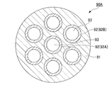
- a first glass rod 90 including a plurality of low refractive index regions 92 that are spaced apart from each other in a region 91 to be a common cladding portion is manufactured.
- the low refractive index region 92 is concentrically formed around the low refractive index region 92A provided in the center of the region 91 serving as the common cladding portion and the region 91 serving as the common cladding portion around the low refractive index region 92A.
- six low refractive index regions 92B provided at approximately equal intervals.
- the region 91 serving as the common cladding portion is made of quartz glass
- the low refractive index region 92 is made of quartz glass to which fluorine is added.
- the refractive index (second refractive index) of the region 91 serving as the common cladding portion is n 12
- the refractive index (third refractive index) of the low refractive index region 92 is n 13 , n 13 ⁇ n 12 Satisfies the relationship.
- the fluorine addition amount is preferably uniform over the entire circumferential direction.
- the variation in the relative refractive index difference is preferably less than 0.01% over the entire circumferential direction.
- a method for manufacturing the first glass rod 90 having such a structure will be described. First, inside the quartz glass tube, a fluorine-added quartz glass rod at the center, a pure quartz glass rod around the fluorine-added quartz glass rod, a fluorine-added quartz glass rod around the pure quartz glass rod, and a fluorine-added quartz glass rod Place a pure quartz glass rod around Next, one end of the quartz glass tube on which the glass rod is disposed is sealed, and the entire quartz glass tube is heated while evacuating the inside of the quartz glass tube from the other open end.
- the first glass rod 90 having the structure shown in FIG. 12 is obtained by softening and filling the gap in the quartz glass tube.
- the diameter of the low refractive index regions 92 and the arrangement of the low refractive index regions 92 in the first glass rod 90 are the second steps inserted into the holes formed in the respective low refractive index regions 92 in a later step.
- the diameter of the glass rod and the optical characteristics (crosstalk) of the desired multi-core optical fiber are appropriately adjusted.
- air holes 93 are formed in each low refractive index region 92 by drilling with a drill at a position where the second glass rod is inserted.
- the holes 93 are formed along the longitudinal direction of the low refractive index region 92 (longitudinal direction of the first glass rod 90) due to the difference in refractive index between the region 91 serving as the common cladding portion and the low refractive index region 92. Since it is processed, there are few processing bends. In this way, the first glass rod 90A with holes with less processing bending of the holes 93 is obtained.
- the portion 101 serving as the core has a refractive index (first refractive index) higher than the refractive index (second refractive index) of the region 91 serving as the common cladding portion.
- the part 102 used as a clad has a lower refractive index (fourth refractive index) than the part 101 used as a core.
- the second glass rod 100 is inserted into each hole 93 formed in the low refractive index region 92.
- the low refractive index region 92 to which fluorine is added remains around each second glass rod 100.
- the low refractive index region 92 is provided between the cores of the multicore optical fiber. There is also an effect of suppressing crosstalk.
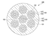
- the multi-core type optical fiber 120 as shown in FIG. 15 is obtained by drawing the glass preform 110 manufactured by the above method.
- the method for drawing the glass base material 110 is not particularly limited, and a known method is used.
- the optical fiber 120 after drawing is preferably coated with various resins by a known method.
- the optical fiber 120 is generally configured by a common clad 121 having a second refractive index and a plurality of optical fiber waveguides 130 disposed in the common clad 121 so as to be separated from each other.
- the optical fiber waveguide 130 satisfies the same configuration as the second glass rod 100, and the core 131 has a refractive index (first refractive index) higher than the refractive index (second refractive index) of the common cladding 121.
- the clad 132 has a lower refractive index (fourth refractive index) than the core 131.
- One optical fiber waveguide 130 is provided at the center of the common cladding 121, and six optical fiber waveguides 130 surround the common cladding 121, are concentrically formed with respect to the common cladding 121, and are provided at approximately equal intervals. Further, a low refractive index portion 122 is provided around the optical fiber waveguide 130.
- the common clad 121 is made of quartz glass, and the low refractive index portion 122 is made of quartz glass to which fluorine is added.
- the refractive index (second refractive index) of the common cladding 121 is n 12 and the refractive index (third refractive index) of the low refractive index portion 122 is n 13 , the relationship of n 13 ⁇ n 12 is satisfied. Yes.
- the optical fiber 120 of the present embodiment is obtained by drawing the glass preform 110 with less processing bending of the air holes 93, the deterioration of crosstalk is suppressed, so that the transmission capacity is greatly improved. Can do.
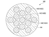
- a first glass rod 140 having a plurality of low-refractive index regions 142 spaced apart from each other in a region 141 to be a common cladding part is produced.
- the low-refractive index regions 142 include six low-refractive index regions 142A provided in the center of the region serving as the common cladding portion and six low-concentration regions that are concentrically formed with respect to the region 141 serving as the common cladding portion.
- the refractive index region 142B and the low refractive index region 142B there are provided six low refractive index regions 142C that are concentrically formed with respect to the region 141 serving as a common cladding portion and are provided at approximately equal intervals.
- the region 141 serving as the common cladding portion is made of quartz glass
- the low refractive index region 142 is made of quartz glass to which fluorine is added.
- the refractive index (second refractive index) of the region 141 serving as the common cladding portion is n 22
- the refractive index (third refractive index) of the low refractive index region 142 is n 23 , n 23 ⁇ n 22 Satisfies the relationship.
- the fluorine addition amount is preferably uniform over the entire circumferential direction.
- the variation in the relative refractive index difference is preferably less than 0.01% over the entire circumference.
- a method for manufacturing the first glass rod 140 having such a structure will be described. First, inside the quartz glass tube, a fluorine-added quartz glass rod at the center, a pure quartz glass rod around it, a fluorine-added quartz glass rod around it, a pure quartz glass rod around it, and a fluorine-added quartz glass rod around it In addition, a pure quartz glass rod is arranged around the periphery. Next, one end of the quartz glass tube on which the glass rod is disposed is sealed, and the entire quartz glass tube is heated while evacuating the inside of the quartz glass tube from the other open end. The first glass rod 140 having the structure shown in FIG. 16 is obtained by softening to fill the gap in the quartz glass tube.
- the diameter of the low refractive index region 142 and the arrangement of the low refractive index region 142 in the first glass rod 140 are the second steps inserted into the holes formed in the respective low refractive index regions 142 in a later step.
- the diameter of the glass rod and the optical characteristics (crosstalk) of the desired multi-core optical fiber are appropriately adjusted.
- a hole 143 is formed by drilling with a drill at a position where the second glass rod is inserted.
- the air holes 143 extend along the longitudinal direction of the low refractive index region 142 (longitudinal direction of the first glass rod 140) due to the difference in refractive index between the region 141 serving as the common cladding portion and the low refractive index region 142. Since it is processed, there are few processing bends. In this way, the first glass rod 140A with holes with less processing bending of the holes 143 is obtained.
- 13 second glass rods 150 each including a core portion 151 and a clad portion 152 disposed around the core portion 151 are prepared (see FIG. 18).
- the core portion 151 has a higher refractive index (first refractive index) than the refractive index (second refractive index) of the region 141 serving as the common cladding portion.
- the part 152 used as a clad has a lower refractive index (fourth refractive index) than the part 151 used as a core.
- the second glass rod 150 is inserted into each hole 143 formed in the low refractive index region 142.
- the low refractive index region 142 to which fluorine is added remains around each second glass rod 150.
- This low refractive index region 142 is provided between the cores of the multicore optical fiber. There is also an effect of suppressing crosstalk.
- a multi-core type optical fiber 170 as shown in FIG. 19 is obtained.
- the method for drawing the glass base material 160 is not particularly limited, and a known method is used.
- the optical fiber 170 after drawing is preferably coated with various resins by a known method.
- the optical fiber 170 is generally composed of a common clad 171 having a second refractive index and a plurality of optical fiber waveguides 180 arranged in the common clad 171 so as to be separated from each other.
- the optical fiber waveguide 180 satisfies the same configuration as the second glass rod 150, and the core 181 has a refractive index (first refractive index) higher than the refractive index (second refractive index) of the common cladding 171.
- the clad 182 has a lower refractive index (fourth refractive index) than the core 181.
- the optical fiber waveguide 180 has one in the center of the common clad 171 and surrounds the periphery thereof.
- the optical fiber waveguide 180 is concentric with the common clad 171 and has six at almost equal intervals. 6 are provided at approximately equal intervals.
- a low refractive index portion 172 is provided around the optical fiber waveguide 180.
- the common clad 171 is made of quartz glass, and the low refractive index portion 172 is made of quartz glass to which fluorine is added.
- the refractive index (second refractive index) of the common cladding 171 is n 22 and the refractive index (third refractive index) of the low refractive index portion 172 is n 23 , the relationship of n 23 ⁇ n 22 is satisfied. Yes.
- the optical fiber 170 of the present embodiment is obtained by drawing the glass base material 160 with less processing bending of the air holes 143, the deterioration of crosstalk is suppressed, so that the transmission capacity is greatly improved. Can do.
- a first low-refractive index region 192 that is concentric with the region 191 that becomes a common cladding portion is provided.
- a glass rod 190 is prepared.
- the region 191 serving as the common cladding portion is made of quartz glass, and the low refractive index region 192 is made of quartz glass to which fluorine is added.
- the refractive index (second refractive index) of the region 191 serving as the common cladding portion is n 32
- the refractive index (third refractive index) of the low refractive index region 192 is n 33 , n 33 ⁇ n 32 Satisfies the relationship.
- the amount of fluorine added is preferably uniform over the entire circumferential direction.
- the variation in the relative refractive index difference is preferably less than 0.01% over the entire circumference.
- a general optical fiber preform manufacturing method such as VAD (Vapor Phase Axial Deposition) method or CVD (Chemical Vapor Deposition) method is applied. Can do.
- VAD Vapor Phase Axial Deposition
- CVD Chemical Vapor Deposition
- the inner diameter and outer diameter of the low refractive index region 192 are determined by the diameter of the second glass rod inserted into the hole formed in the low refractive index region 192 in a later step, and the desired multi-core optical fiber. It is adjusted as appropriate according to the optical characteristics (crosstalk).
- holes 193 are formed by drilling with a drill at the position where the second glass rod is inserted.
- six voids 193 are formed in the low refractive index region 192 so as to be spaced apart from each other and concentrically with respect to the region 191 serving as a common cladding portion at substantially equal intervals.
- the air holes 193 are formed along the longitudinal direction of the low refractive index region 192 (longitudinal direction of the first glass rod 190) due to the difference in refractive index between the region 191 serving as a common cladding portion and the low refractive index region 192. Since it is processed, there are few processing bends.
- the present invention is not limited to this.
- the position where the hole is formed may not be the central portion of the low refractive index region. In this way, the first glass rod 190A with holes with less processing bending of the holes 193 is obtained.
- the portion 201 serving as the core has a refractive index (first refractive index) higher than the refractive index (second refractive index) of the region 191 serving as the common cladding portion.
- the part 202 used as a clad has a lower refractive index (fourth refractive index) than the part 201 used as a core.
- the second glass rod 200 is inserted into each hole 193 formed in the low refractive index region 192.
- the obtained glass base material 210 has a low refractive index region 192 to which fluorine is added around each second glass rod 200.
- This low refractive index region 192 is provided between the cores of the multi-core optical fiber. There is also an effect of suppressing crosstalk.
- a multi-core optical fiber 220 as shown in FIG. 23 is obtained.
- the method for drawing the glass base material 210 is not particularly limited, and a known method is used.
- the optical fiber 220 after drawing is preferably coated with various resins by a known method.
- the optical fiber 220 includes a common clad 221 having a second refractive index, an annular low refractive index portion 222 disposed concentrically with the common clad 221 in the common clad 221, and a low refractive index portion 222.
- the optical fiber waveguide 230 is roughly composed of six optical fiber waveguides 230 that are spaced apart from each other and arranged concentrically with the common clad 221 at substantially equal intervals.
- the optical fiber waveguide 230 has the same configuration as the second glass rod 200, and the core 231 has a refractive index (first refractive index) higher than the refractive index (second refractive index) of the common cladding 221.
- Have The clad 232 has a lower refractive index (fourth refractive index) than the core 231.
- the common clad 221 is made of quartz glass, and the low refractive index portion 222 is made of quartz glass to which fluorine is added.
- the refractive index (second refractive index) of the common cladding 221 is n 32 and the refractive index (third refractive index) of the low refractive index portion 222 is n 33 , the relationship of n 33 ⁇ n 32 is satisfied. Yes.
- the optical fiber 220 of the present embodiment is obtained by drawing the glass preform 210 with less processing bending of the air holes 193, deterioration of crosstalk is suppressed, so that the transmission capacity is greatly improved. Can do.
- a first glass rod 240 having a low refractive index region 242 in a region 241 serving as a common cladding portion is produced.
- the low refractive index region 242 includes a low refractive index region 242A provided in the center of the region 241 serving as a common cladding portion, and a first glass rod 240 (region 241 serving as a common cladding portion) around the low refractive index region 242A.
- an annular low refractive index region 242B provided concentrically.
- the region 241 serving as the common cladding portion is made of quartz glass
- the low refractive index region 242 is made of quartz glass to which fluorine is added.
- the refractive index (second refractive index) of the region 241 serving as the common cladding portion is n 42
- the refractive index (third refractive index) of the low refractive index region 242 is n 43 , n 43 ⁇ n 42 Satisfies the relationship.
- the amount of fluorine added is uniform over the entire circumference.
- the variation in the relative refractive index difference is preferably less than 0.01% over the entire circumference.
- a general optical fiber preform manufacturing method such as a VAD (Vapor phase Axial Deposition) method or a CVD (Chemical Vapor Deposition) method is applied. Can do.
- VAD Vapor phase Axial Deposition
- CVD Chemical Vapor Deposition
- the outer diameter of the low refractive index region 242A and the inner diameter and outer diameter of the low refractive index region 242B are the second glass rods inserted into holes formed in the low refractive index region 242 in a later step. , And the optical characteristics (crosstalk) of the desired multi-core optical fiber are appropriately adjusted.
- a hole 243 is formed by drilling with a drill at a position where the second glass rod is inserted.
- one hole 243 is formed in the low refractive index region 242A, and the low refractive index region 242B is spaced apart from each other so as to be concentric with the region 241 serving as a common cladding portion.
- Six holes 243 are formed at intervals.
- the air holes 243 extend along the longitudinal direction of the low refractive index region 242 (longitudinal direction of the first glass rod 240) due to the difference in refractive index between the region 241 serving as the common cladding portion and the low refractive index region 242. Since it is processed, there is little processing bending. In this manner, the first glass rod 240A with holes with less processing bending of the holes 243 is obtained.
- the portion 251 serving as a core has a refractive index (first refractive index) higher than the refractive index (second refractive index) of the region 241 serving as a common cladding portion.
- the portion 252 serving as the cladding has a lower refractive index (fourth refractive index) than the portion 251 serving as the core.
- the second glass rod 250 is inserted into each hole 243 formed in the low refractive index region 242.
- the obtained glass preform 260 has a low refractive index region 242 to which fluorine is added around each second glass rod 250, and this low refractive index region 242 is provided between the cores of the multi-core optical fiber. There is also an effect of suppressing crosstalk.
- a multi-core type optical fiber 270 as shown in FIG. 27 is obtained.
- the method for drawing the glass base material 260 is not particularly limited, and a known method is used.
- the optical fiber 270 after drawing is preferably coated with various resins by a known method.
- the optical fiber 270 includes a common clad 271 having a second refractive index, a low refractive index portion 272 (272A) disposed at the center of the common clad 271 and a 1 disposed within the low refractive index portion 272 (272A).
- the optical fiber waveguide 280 is roughly composed of six optical fiber waveguides 280 that are spaced apart from each other and concentrically with respect to the common clad 261.
- the optical fiber waveguide 280 has the same configuration as the second glass rod 250, and the core 281 has a higher refractive index (first refractive index) than the refractive index (second refractive index) of the common cladding 271.
- the clad 282 has a lower refractive index (fourth refractive index) than the core 281.
- the common clad 271 is made of quartz glass, and the low refractive index portion 272 is made of quartz glass to which fluorine is added.
- the refractive index (second refractive index) of the common cladding 271 is n 42 and the refractive index (third refractive index) of the low refractive index portion 272 is n 43 , the relationship of n 43 ⁇ n 42 is satisfied. Yes.
- the optical fiber 270 of the present embodiment is obtained by drawing the glass base material 260 with less processing bending of the air holes 243, the deterioration of the crosstalk is suppressed, so that the transmission capacity is greatly improved. Can do.
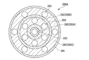
- a first glass rod 290 having a low refractive index region 292 in a region 291 that becomes a common cladding portion is produced.
- the low-refractive index region 292 is provided concentrically with the low-refractive index region 292A provided in the center of the region serving as the common cladding portion and the region 281 serving as the common cladding portion around the low-refractive index region 292A.
- An annular low-refractive index region 292B and an annular low-refractive index region 292C provided concentrically with the region 291 serving as a common cladding portion are provided around the low-refractive index region 292B.
- the region 291 serving as the common cladding portion is made of quartz glass
- the low refractive index region 292 is made of quartz glass to which fluorine is added.
- the refractive index (second refractive index) of the region 291 serving as the common cladding portion is n 52
- the refractive index (third refractive index) of the low refractive index region 292 is n 53 , n 53 ⁇ n 52 Satisfies the relationship.
- the amount of fluorine added is preferably uniform over the entire circumferential direction.
- the variation in the relative refractive index difference is preferably less than 0.01% over the entire circumference.
- a general optical fiber preform manufacturing method such as a VAD (Vapor Phase Axial Deposition) method or a CVD (Chemical Vapor Deposition) method is applied. Can do.
- VAD Vapor Phase Axial Deposition
- CVD Chemical Vapor Deposition
- the outer diameter of the low refractive index region 292A, the inner diameter and outer diameter of the low refractive index region 292B, and the inner diameter and outer diameter of the low refractive index region 292C are formed in the low refractive index region 292 in a later step. It adjusts suitably according to the diameter of the 2nd glass rod inserted in a void
- holes 293 are formed in the low refractive index region 292 by drilling with a drill at the position where the second glass rod is inserted.
- one hole 293 is formed in the low refractive index region 292A.
- six holes 293 are formed in the low refractive index region 292 ⁇ / b> B so as to be spaced apart from each other and concentrically with respect to the region 291 to be a common clad portion at substantially equal intervals.
- six holes 293 are formed in the low-refractive index region 292C so as to be spaced apart from each other and concentrically with respect to the region 291 serving as the common cladding portion at substantially equal intervals.
- the air holes 293 are formed along the longitudinal direction of the low refractive index region 292 (longitudinal direction of the first glass rod 290) due to the difference in refractive index between the region 291 serving as the common cladding portion and the low refractive index region 292. Since it is processed, there are few processing bends. In this way, the first glass rod 290A with holes with less processing bending of the holes 293 is obtained.
- 13 second glass rods 300 each having a core portion 301 and a clad portion 302 disposed around the core portion 301 are prepared (see FIG. 30).
- the core portion 301 has a higher refractive index (first refractive index) than the refractive index (second refractive index) of the cladding portion 302.
- the portion 302 serving as the cladding has a lower refractive index (fourth refractive index) than the portion 301 serving as the core.
- the second glass rod 300 is inserted into each hole 293 formed in the low refractive index region 292.
- the low refractive index region 292 to which fluorine is added remains around each second glass rod 300.
- This low refractive index region 292 is provided between the cores of the multi-core optical fiber. There is also an effect of suppressing crosstalk.
- a multi-core type optical fiber 320 as shown in FIG. 31 is obtained.
- the method for drawing the glass base material 310 is not particularly limited, and a known method is used.
- the optical fiber 320 after drawing is preferably coated with various resins by a known method.
- the optical fiber 320 includes a common clad 321 having a second refractive index, a low refractive index portion 322A (322) disposed at the center of the common clad 321 and a low refractive index portion 322A (322).
- the six optical fiber waveguides 330 arranged concentrically with respect to the common cladding 321 and spaced apart from each other, and the low refractive index portion 322B (322 in the common cladding 321).
- the optical fiber waveguide 330 has the same configuration as that of the second glass rod 300, and the core 331 has a refractive index (first refractive index) higher than the refractive index (second refractive index) of the common cladding 321.
- Have The clad 332 has a lower refractive index (fourth refractive index) than the core 331.
- the common clad 321 is made of quartz glass, and the low refractive index portion 322 is made of quartz glass to which fluorine is added.
- the refractive index (second refractive index) of the common cladding 321 is n 52 and the refractive index (third refractive index) of the low refractive index portion 322 is n 53 , the relationship of n 53 ⁇ n 52 is satisfied. Yes.
- the optical fiber 320 of the present embodiment is obtained by drawing the glass base material 310 with less processing bending of the air holes 293, the deterioration of crosstalk is suppressed, so that the transmission capacity is greatly improved. Can do.
- the 1st glass rod 90 provided with the some low-refractive-index area
- the low-refractive index region 92 is concentrically formed around the low-refractive index region 92A and the low-refractive index region 92A around the low-refractive index region 92A.
- six low refractive index regions 92B provided at approximately equal intervals.
- the region 91 serving as the common cladding portion is made of quartz glass, and the low refractive index region 92 is made of quartz glass to which fluorine is added.
- the first glass rod 90 had an outer diameter of 100 mm and a length of 1000 mm.
- the outer diameter of the low refractive index region 92 was 19 mm. Further, assuming that the refractive index (second refractive index) of the region 91 serving as the common cladding portion is n 12 , and the refractive index (third refractive index) of the low refractive index region 92 is n 13 , n 13 ⁇ n 12 The relationship was met. Furthermore, the relative refractive index difference of the low refractive index region 92 was 0.7%.
- a hole 93 was formed at a position where the second glass rod was inserted by drilling with a drill.
- the outer diameter of the tip of the drill tool is 18 mm
- the drilling length is 1000 mm
- a through hole is formed along the longitudinal direction of the first glass rod 90
- the first glass rod with holes is formed 90A was obtained.
- seven second glass rods 100 each having a core portion 101 and a clad portion 102 disposed around the core portion 101 were prepared (see FIG. 14).
- the second glass rod 100 described above was inserted into each hole 93 formed in the low refractive index region 92.
- the first glass rod 90A and the second glass rod 100 are integrated, and a cross section as shown in FIG.
- the glass base material 110 which has this was obtained.
- the optical fiber 120 is generally configured by a common clad 121 having a second refractive index and a plurality of optical fiber waveguides 130 disposed in the common clad 121 so as to be separated from each other.
- One optical fiber waveguide 130 is provided at the center of the common clad 121, and there are six optical fiber waveguides that surround the periphery of the common clad 121, concentrically with the common clad 121, and at approximately equal intervals.
- the core 131 has a refractive index (first refractive index) higher than the refractive index (second refractive index) of the common cladding 121.
- the clad 132 has a lower refractive index (fourth refractive index) than the core 131.
- a low refractive index portion 122 is provided around the optical fiber waveguide 130. Further, when the refractive index (second refractive index) of the common cladding 121 is n 12 and the refractive index (third refractive index) of the low refractive index portion 122 is n 13 , the relationship of n 13 ⁇ n 12 is satisfied. It was.
- region 241 used as a common clad part was produced.
- the low refractive index region 242 is provided concentrically with the low refractive index region 242A provided in the center of the region 241 serving as the common cladding portion and the region 241 serving as the common cladding portion around the low refractive index region 242A.
- the region 241 serving as the common cladding portion is made of quartz glass, and the low refractive index region 242 is made of quartz glass to which fluorine is added.
- the outer diameter of the region 241 serving as the common clad portion was 100 mm and the length was 1000 mm. Further, the thickness of the low refractive index region 242 was 19 mm. Further, assuming that the refractive index (second refractive index) of the region 241 serving as the common cladding portion is n 42 , and the refractive index (third refractive index) of the low refractive index region 242 is n 43 , n 43 ⁇ n 42 The relationship was met. Furthermore, the relative refractive index difference of the low refractive index region 242 was 0.7%.
- holes 243 were formed in the low refractive index region 242 by drilling with a drill at the position where the second glass rod was inserted.
- one hole 243 is formed in the low refractive index region 242A, and the low refractive index region 242B is spaced apart from each other so as to be concentric with the region 241 serving as a common cladding portion.
- Six holes 243 were formed at intervals.
- the outer diameter of the tip of the drill tool is 18 mm
- the processing length by drilling is 1000 mm
- a through hole is formed along the longitudinal direction of the first glass rod 240, and the first glass rod with holes is formed 240A was obtained.
- first glass rod 240A in which the second glass rod 250 is inserted, the first glass rod 240A and the second glass rod 250 are integrated, and a cross section as shown in FIG. A glass preform 260 having
- the optical fiber 270 includes a common clad 271 having a second refractive index, a low refractive index portion 272 (272A) disposed at the center of the common clad 271 and a 1 disposed within the low refractive index portion 272 (272A).
- the optical fiber waveguide 280 is roughly composed of six optical fiber waveguides 280 that are spaced apart and arranged concentrically with the common clad 271 at substantially equal intervals.
- the core 281 has a refractive index (first refractive index) higher than the refractive index (second refractive index) of the common cladding 271.
- the clad 282 has a lower refractive index (fourth refractive index) than the core 281. Further, a low refractive index portion 272 is provided around the optical fiber waveguide 280.
- the refractive index (second refractive index) of the common cladding 271 is n 42
- the refractive index (third refractive index) of the low refractive index portion 272 is n 43
- the relationship of n 43 ⁇ n 42 is satisfied. It was.
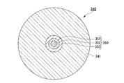
- positioned around was added was produced.
- the first glass rod 340 had an outer diameter of 100 mm and a length of 1000 mm.
- the refractive index of the region 341 serving as the common cladding portion is n 102
- the refractive index of the low refractive index portion 353 is n 103
- the relationship of n 103 ⁇ n 102 is satisfied.
- the common cladding portion is formed by drilling with a drill at a position where the core material is inserted (here, around the low refractive index portion 353).
- Six vacancies 342 were formed substantially equidistantly in a concentric manner with respect to the region 341.
- the outer diameter of the tip of the drill tool is 18 mm
- the processing length by drilling is 1000 mm
- a through hole is formed along the longitudinal direction of the first glass rod 340, and the first glass rod with holes is formed 340A was obtained.
- a second portion 351 including a core portion 351, a clad portion 352 disposed around the core portion 351, and a low refractive index portion 353 to which fluorine is disposed around the core portion 351 is provided.
- Six glass rods 350 were prepared (see FIG. 34).
- the second glass rod 350 described above was inserted into each hole 332 formed in the region 341 to be the common cladding portion.
- the first glass rod 340A and the second glass rod 350 are integrated, and a cross section as shown in FIG.
- the glass base material 360 which has this was obtained.
- a multi-core optical fiber 370 having an outer diameter of 140 ⁇ m as shown in FIG. 35 was obtained.
- the optical fiber 370 is separated from each other around the common cladding 371, the optical fiber waveguide 380 disposed in the center of the common cladding 371, and the optical fiber waveguide 380 disposed in the center in the common cladding 371.
- the optical fiber waveguide 380 includes a core 371, a clad 372 disposed around the core 371, and a low refractive index region 373 to which fluorine is added disposed around the clad 372. Further, when the refractive index of the clad 361 is n 102 and the refractive index of the low refractive index region 373 is n 103 , the relationship of n 103 ⁇ n 102 is satisfied.
- Example 1 and 2 and a comparative example evaluation of the amount of process bending was performed by the following three methods.
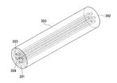
- the positions of the air holes 393 were measured on the processing start end surface 391 and the processing end end surface 392 of the first glass rod 390.
- the distances from the center of the first glass rod 390 (center of the core 394) to the centers of the six holes 393 are defined as Rs1, Rs2, Rs3, Rs4, Rs5, and Rs6, respectively.
- the distances Rs1 to Rs6 were measured.
- the average value of these distances Rs1 to Rs6 was defined as the hole position Rs on the machining start end surface 391.
- the distance from the center of the first glass rod 390 (center of the core 394) to the center of the six holes 393 is defined as Re1, Re2, Re3, Re4, Re5, and Re6 on the processing end face 392, respectively.
- the distances Re1 to Re6 were measured.
- an average value of these distances Re1 to Re6 was defined as a hole position Re in the processing end face 392.
- the processing bending amount ⁇ R in the first glass rod 390 was defined as
- the average value of these distances ⁇ s1 to ⁇ s6 was defined as the inter-core distance ⁇ s at the end face corresponding to the machining start end face.
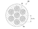
- the distance from the center of the central core 401 to the centers of the six outer cores 402 is defined as ⁇ e1, ⁇ e2, ⁇ e3, ⁇ e4, ⁇ e5, and ⁇ e6 on the end surface corresponding to the processing end surface, and the distances ⁇ e1 ⁇ ⁇ e6 was measured.
- the average value of these distances ⁇ e1 to ⁇ e6 was defined as the inter-core distance ⁇ e at the end face corresponding to the end face of processing.
- the processing bending amount ⁇ in the optical fiber 400 was defined as
- crosstalk was measured by the following method.
- Light is incident on one of the cores (for example, a core provided at the center) from one end surface (first end surface) of the optical fiber from the light source, and the core (for example, the light is incident on the other end surface of the optical fiber).
- the intensity of light output from the core provided in the center is measured.
- a core different from the core on which light is incident for example, a core provided so as to surround the core provided in the center
- the intensity of the light output from the core for example, the core provided at the center
- the core different from the core for example, the core provided at the center
- the crosstalk value is calculated from the ratio with the intensity of light output from the core. The results are shown in Table 1.
- low refractive index part 80 ... optical fiber waveguide, 81 ... core, 82 ... cladding, 190 ... first glass rod, 191 ... common clad portion 192 ... low refractive index region, 193 ... hole, 200 ... second glass rod, 201 ... core portion, 202 ... cladding portion, 210 ... Glass base material, 220: optical fiber, 221: common clad, 222: low refractive index portion, 230: optical fiber waveguide, 231: core, 232: clad.
Landscapes
- Engineering & Computer Science (AREA)
- Chemical & Material Sciences (AREA)
- Geochemistry & Mineralogy (AREA)
- Life Sciences & Earth Sciences (AREA)
- General Life Sciences & Earth Sciences (AREA)
- Physics & Mathematics (AREA)
- Manufacturing & Machinery (AREA)
- Materials Engineering (AREA)
- Organic Chemistry (AREA)
- Optics & Photonics (AREA)
- General Physics & Mathematics (AREA)
- Manufacture, Treatment Of Glass Fibers (AREA)
- Optical Fibers, Optical Fiber Cores, And Optical Fiber Bundles (AREA)
Abstract
本発明の製造方法は、複数のコアを有する光ファイバの製造方法であって、第二の屈折率を有する共通クラッド部となる領域内に互いに離隔して配置された複数の低屈折率領域を備え、前記低屈折率領域にはフッ素が添加され、かつ、前記第二の屈折率よりも低い第三の屈折率を有する第一のガラスロッドを準備し、前記複数の低屈折率領域のそれぞれの内部に空孔を形成し、前記第二の屈折率よりも高い第一の屈折率を有するコアとなる部分と、前記コアとなる部分の周囲に配置され、前記第一の屈折率よりも低い第四の屈折率を有するクラッドとなる部分と、を備えた第二のガラスロッドを複数準備し、前記複数の低屈折率領域内に形成されたそれぞれの空孔内に前記第二のガラスロッドを挿入し、前記第一のガラスロッドと前記第二のガラスロッドとを一体化してガラス母材を作製し、前記ガラス母材を線引きする線引きする。
Description
本発明は、光ファイバおよび光ファイバの製造方法に関する。
本願は、2012年8月31日に出願された特願2012-192595号に基づき優先権を主張し、その内容をここに援用する。
本願は、2012年8月31日に出願された特願2012-192595号に基づき優先権を主張し、その内容をここに援用する。
光ファイバを高機能化するために、複雑な構造を有する光ファイバが製品化されている。このような複雑な構造を有する光ファイバを製造する方法も複雑である。
このような光ファイバとしては、マルチコア光ファイバが挙げられる。マルチコア光ファイバは、1本の光ファイバに、複数のコアが設けられた構造を有し、近年、伝送容量を大幅に拡大できる光ファイバとして注目を集めている。
マルチコア光ファイバ用のガラス母材の作製方法としては、例えば、石英クラッド材に貫通孔を形成し、その貫通孔にコア材を挿入して、石英クラッド材及びにコア材の両者を加熱し、一体化するコラプス法が挙げられる。石英クラッド材に貫通孔を形成する方法としては、一般的にドリルによる穿孔加工が用いられる(例えば、特許文献1参照)。
このような光ファイバとしては、マルチコア光ファイバが挙げられる。マルチコア光ファイバは、1本の光ファイバに、複数のコアが設けられた構造を有し、近年、伝送容量を大幅に拡大できる光ファイバとして注目を集めている。
マルチコア光ファイバ用のガラス母材の作製方法としては、例えば、石英クラッド材に貫通孔を形成し、その貫通孔にコア材を挿入して、石英クラッド材及びにコア材の両者を加熱し、一体化するコラプス法が挙げられる。石英クラッド材に貫通孔を形成する方法としては、一般的にドリルによる穿孔加工が用いられる(例えば、特許文献1参照)。
マルチコア光ファイバは、伝送容量を大幅に拡大できるという特長を持つ光ファイバであることから、長距離伝送用途において、その特長を発揮し得る光ファイバである。すなわち、マルチコア光ファイバは、長尺使用が想定されるため、マルチコア光ファイバ用のガラス母材も大型化が必要となる。しかしながら、ガラス母材の大型化に伴って、石英クラッド材に対するドリルによる穿孔加工の加工長も長くなるため、貫通孔の曲がりが顕著となるという課題があった。仮に、石英クラッド材に形成された貫通孔が曲がったまま、貫通孔にコア材を挿入することができて、ガラス母材とコア材を一体化し、一体化されたガラス母材を線引きして、光ファイバが得られたとしても、光ファイバの長手方向において、コア間の距離が近付いてしまい、コア間でクロストークが劣化する可能性があった。
本発明は、上記事情に鑑みてなされたものであって、加工曲がりおよびクロストークの劣化を抑制した光ファイバおよび光ファイバの製造方法を提供することを目的とする。
上記課題を解決するため、本発明の第一態様における複数のコアを有する光ファイバの製造方法は、第二の屈折率を有する共通クラッド部となる領域内に互いに離隔して配置された複数の低屈折率領域を備え、前記低屈折率領域にはフッ素が添加され、かつ、前記第二の屈折率よりも低い第三の屈折率を有する第一のガラスロッドを準備し、前記複数の低屈折率領域のそれぞれの内部に空孔を形成し、前記第二の屈折率よりも高い第一の屈折率を有するコアとなる部分と、前記コアとなる部分の周囲に配置され、前記第一の屈折率よりも低い第四の屈折率を有するクラッドとなる部分と、を備えた第二のガラスロッドを複数準備し、前記複数の低屈折率領域内に形成されたそれぞれの空孔内に前記第二のガラスロッドを挿入し、前記第一のガラスロッドと前記第二のガラスロッドとを一体化してガラス母材を作製し、前記ガラス母材を線引きする線引きする。
本発明の第二態様における複数のコアを有する光ファイバの製造方法は、第二の屈折率を有する共通クラッド部となる領域内に環状の低屈折率領域を備え、前記低屈折率領域にはフッ素が添加され、かつ、前記第二の屈折率よりも低い第三の屈折率を有する第一のガラスロッドを準備し、前記低屈折率領域内に、互いに離隔する複数の空孔を形成し、前記第二の屈折率よりも高い第一の屈折率を有するコアとなる部分と、前記コアとなる部分の周囲に配置され、前記第一の屈折率よりも低い第四の屈折率を有するクラッドとなる部分と、を備えた第二のガラスロッドを複数準備し、前記低屈折率領域内に形成されたそれぞれの空孔内に前記第二のガラスロッドを挿入し、前記第一のガラスロッドと前記第二のガラスロッドとを一体化してガラス母材を作製し、前記ガラス母材を線引きする線引きする。
本発明の第二態様の製造方法においては、前記第一のガラスロッドを準備する際に、前記共通クラッド部となる領域の中央に前記低屈折率領域を設け、前記空孔を形成する際に、前記共通クラッド部となる領域に形成された前記低屈折率領域内に空孔を形成することが好ましい。
本発明の第二態様の製造方法においては、前記第一のガラスロッドを準備する際に、前記共通クラッド部となる領域に、同心円状に前記低屈折率領域を複数設けることが好ましい。
本発明の第一態様又は第二態様の製造方法においては、前記ガラス母材の作製と、前記線引きとを同時に行うことが好ましい。
本発明の第三態様における複数のコアを有する光ファイバは、第二の屈折率を有する共通クラッドと、前記第二の屈折率よりも高い第一の屈折率を有するコアと、前記コアの周囲に配置されて前記第四の屈折率を有するクラッドとを備えるとともに、前記共通クラッド内に互いに離隔して配置された複数の光ファイバ導波路と、前記光ファイバ導波路の周囲に設けられ、フッ素が添加され、前記第二の屈折率よりも低い第三の屈折率を有する低屈折率部とを含む。
本発明の第四態様における複数のコアを有する光ファイバは、複数のコアを有する光ファイバであって、第二の屈折率を有する共通クラッドと、前記第二の屈折率よりも低い第三の屈折率を有するとともに、フッ素が添加され、前記共通クラッド内に設けられた環状の低屈折率部と、前記第二の屈折率よりも高い第一の屈折率を有するコアと、前記コアの周囲に配置されて前記第四の屈折率を有するクラッドとを備えるとともに、前記低屈折率部内に互いに離隔して配置された複数の光ファイバ導波路とを含む。
本発明の第四態様における光ファイバにおいては、前記共通クラッドの中央に、前記光ファイバ導波路が設けられ、当該光ファイバ導波路の周囲に前記低屈折率部が設けられたことが好ましい。
本発明の第四態様における光ファイバにおいては、前記共通クラッド内に、同心円状に前記低屈折率部が複数設けられたことが好ましい。
本発明の第一態様、第二態様、第三態様、及び第四態様によれば、加工曲がりおよびクロストークの劣化を抑制した光ファイバを提供することができる。
本発明の光ファイバおよび光ファイバの製造方法の実施の形態について説明する。
なお、本実施の形態は、発明の趣旨をより良く理解させるために具体的に説明するものであり、特に指定のない限り、本発明を限定するものではない。
なお、本実施の形態は、発明の趣旨をより良く理解させるために具体的に説明するものであり、特に指定のない限り、本発明を限定するものではない。
石英ガラスからなるガラス母材に対する、ドリルによる穿孔加工における加工曲がりの対策としては、(1)適切なドリルツールの選択(ツールの剛性、ドリル径、砥粒密度、砥粒径など)、(2)ドリルによる穿孔加工条件の適正化(加工速度、ドリル回転数など)が知られている。
本発明者等は、鋭意検討を重ねた結果、ドリルによる穿孔加工における加工曲がりと、ガラス母材の断面内における組成分布とは相関があることを見出した。
以下、ドリルによる穿孔加工における加工曲がりと、ガラス母材の断面内における組成分布との相関について、具体的に説明する。
本発明者等は、鋭意検討を重ねた結果、ドリルによる穿孔加工における加工曲がりと、ガラス母材の断面内における組成分布とは相関があることを見出した。
以下、ドリルによる穿孔加工における加工曲がりと、ガラス母材の断面内における組成分布との相関について、具体的に説明する。
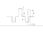
ここで、図1に示すような屈折率プロファイルを有するガラス母材について考える。
このガラス母材は、中心にゲルマニウムが添加された石英ガラスからなる高屈折率コア1と、高屈折率コア1の周囲に設けられて高屈折率コア1よりも屈折率が低く、かつ、石英ガラスからなる内側クラッド2と、内側クラッド2の周囲に設けられて内側クラッド2よりも屈折率が低く、フッ素が添加された低屈折率クラッド3(以下、「フッ素添加クラッド」と言う。)と、フッ素添加クラッド3の周囲に設けられて内側クラッド2と屈折率が等しく、石英ガラスからなる外側クラッド4を有する構造を有する。
このガラス母材は、中心にゲルマニウムが添加された石英ガラスからなる高屈折率コア1と、高屈折率コア1の周囲に設けられて高屈折率コア1よりも屈折率が低く、かつ、石英ガラスからなる内側クラッド2と、内側クラッド2の周囲に設けられて内側クラッド2よりも屈折率が低く、フッ素が添加された低屈折率クラッド3(以下、「フッ素添加クラッド」と言う。)と、フッ素添加クラッド3の周囲に設けられて内側クラッド2と屈折率が等しく、石英ガラスからなる外側クラッド4を有する構造を有する。
このような屈折率プロファイルを有するガラス母材に対して、ドリルによる穿孔加工を行う場合について考える。
例えば、図2に示すように、フッ素添加クラッド3と外側クラッド4との境界部において、ドリルツール11による穿孔加工を行うと、図2において矢印で示す方向、すなわち、フッ素添加クラッド3とは反対側に向く方向(ガラス母材の外側方向)に加工曲がりが生じる傾向がある。
一方、図3に示すように、内側クラッド2とフッ素添加クラッド3の境界部において、ドリルツール11による穿孔加工を行うと、図3において矢印で示す方向、すなわち、フッ素添加クラッド3とは反対側に向く方向(ガラス母材の内側方向)に加工曲がりが生じる傾向がある。
例えば、図2に示すように、フッ素添加クラッド3と外側クラッド4との境界部において、ドリルツール11による穿孔加工を行うと、図2において矢印で示す方向、すなわち、フッ素添加クラッド3とは反対側に向く方向(ガラス母材の外側方向)に加工曲がりが生じる傾向がある。
一方、図3に示すように、内側クラッド2とフッ素添加クラッド3の境界部において、ドリルツール11による穿孔加工を行うと、図3において矢印で示す方向、すなわち、フッ素添加クラッド3とは反対側に向く方向(ガラス母材の内側方向)に加工曲がりが生じる傾向がある。
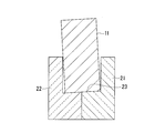
石英ガラスにフッ素を添加すると、石英ガラス中の一部のSi-O-Si結合が切断され、その結合が切断された部分にフッ素(F)が結合して、Si-F結合を形成する。すると、ガラス構造の密度がより低く(疎)なり、Si-F結合を形成している部分の密度や弾性率が低下する。よって、図2や図3に示すような屈折率プロファイルを有するガラス母材において、純粋な石英ガラスからなる内側クラッド2とフッ素添加クラッド3との境界部において、または、純粋な石英ガラスからなる外側クラッド4とフッ素添加クラッド3との境界部において、ドリルツール11による穿孔加工を行った場合、ガラス構造の密度が低い(疎)フッ素添加クラッド3がより促進的に穿孔される。その結果、図4の模式図に示すように、石英ガラス部21(内側クラッド2、外側クラッド4)とフッ素添加石英ガラス部22(フッ素添加クラッド3)の境界部に対して垂直に、ドリルツール11による穿孔加工を行おうとしても、加工面23は、ガラス母材の長手方向に対して傾くように形成される。
そして、加工面23が傾いた状態で穿孔加工を続けると、図5に示すように、ドリルツール11にかかる剛性によって、加工面23に沿って、ドリルツール11の先端が曲がり、その結果として、加工曲がりが生じると考えられる。
そして、加工面23が傾いた状態で穿孔加工を続けると、図5に示すように、ドリルツール11にかかる剛性によって、加工面23に沿って、ドリルツール11の先端が曲がり、その結果として、加工曲がりが生じると考えられる。
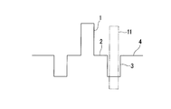
これに対して、図6に示すように、フッ素添加クラッド3のみに、ドリルツール11による穿孔加工を行った場合、ドリルツール11は、ガラス構造の密度が低い(疎)領域のみに対して穿孔加工を行うことになる。このため、ドリルツール11がガラス母材の長手方向に対して傾くことがなく、フッ素添加クラッド3の長手方向(ガラス母材の長手方向)に沿って、穿孔加工が行われる。その結果、穿孔加工の加工長全長において、加工曲がりが抑えられる。
すなわち、本発明では、ガラス母材の断面において、穿孔加工を行う領域とそれ以外の領域との間に屈折率差を設けることにより、ガラス母材の長手方向全長において、穿孔加工時の加工曲がりを抑制し、結果的に、光ファイバの長手方向全長において、コアが所望の位置に設けられたマルチコア光ファイバを製造することが可能となる。
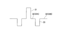
本発明において、有効なフッ素添加量を、無添加の純粋石英ガラスに対する、低屈折率クラッド(フッ素添加クラッド3)の比屈折率差(Δh)によって定義する。本発明において、比屈折率差(Δh)は0.01%以上であることが好ましい。比屈折率差(Δh)が0.01%未満であると、加工曲がりが発生するおそれがある。また、フッ素が添加された石英ガラスからなるクラッド(以下、「フッ素添加クラッド」と言う。)を有する純シリカコアファイバに孔開加工を行う場合には、図7に示すように、純シリカコア31の周囲に設けられたフッ素添加クラッド32において、穿孔加工領域のフッ素添加量を変えて、低屈折率フッ素添加クラッド33を形成することによって、内側クラッド32Aまたは外側クラッド32Bに対する、低屈折率フッ素添加クラッド33の比屈折率差(Δh)を設けることができる。
(1)第一実施形態
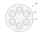
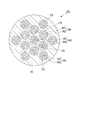
図8に示すように、共通クラッド部となる領域41内に、互いに離隔して配置された複数の低屈折率領域42を備えた第一のガラスロッド40を作製する。
低屈折率領域42は、第一のガラスロッド40(共通クラッド部となる領域41)に対して同心円状に、ほぼ等間隔に6つ設けられている。
共通クラッド部となる領域41は、石英ガラスから構成され、低屈折率領域42は、フッ素が添加された石英ガラスから構成されている。
図8に示すように、共通クラッド部となる領域41内に、互いに離隔して配置された複数の低屈折率領域42を備えた第一のガラスロッド40を作製する。
低屈折率領域42は、第一のガラスロッド40(共通クラッド部となる領域41)に対して同心円状に、ほぼ等間隔に6つ設けられている。
共通クラッド部となる領域41は、石英ガラスから構成され、低屈折率領域42は、フッ素が添加された石英ガラスから構成されている。
また、共通クラッド部となる領域41の屈折率(第二の屈折率)をn2、低屈折率領域42の屈折率(第三の屈折率)をn3とすると、n3<n2の関係を満たしている。
低屈折率領域42において、全周方向にわたって、フッ素添加量は均一であることが好ましい。また、低屈折率領域42において、全周方向にわたって、比屈折率差のばらつきは0.01%未満であることが好ましい。
ここで、無添加の純粋石英ガラスの屈折率(ここでは、共通クラッド部となる領域41の屈折率)をn2、純粋石英ガラスにおけるある部分において、ドーパントが添加された領域(ドーパント(ここでは、フッ素)添加領域)があり、その部分の屈折率(ここでは、低屈折率領域42の屈折率)をn3と定義したとき、比屈折率差Δは、下記の式(1)によって定義される。
低屈折率領域42において、全周方向にわたって、フッ素添加量は均一であることが好ましい。また、低屈折率領域42において、全周方向にわたって、比屈折率差のばらつきは0.01%未満であることが好ましい。
ここで、無添加の純粋石英ガラスの屈折率(ここでは、共通クラッド部となる領域41の屈折率)をn2、純粋石英ガラスにおけるある部分において、ドーパントが添加された領域(ドーパント(ここでは、フッ素)添加領域)があり、その部分の屈折率(ここでは、低屈折率領域42の屈折率)をn3と定義したとき、比屈折率差Δは、下記の式(1)によって定義される。

このような構造を有する第一のガラスロッド40の製造方法を説明する。
まず、石英ガラス管の内部において、中心に純粋石英ガラスロッド、純粋石英ガラスロッドの周囲にフッ素添加石英ガラスロッド、さらに、フッ素添加石英ガラスロッドの周囲に純粋石英ガラスロッドを配置する。
次に、ガラスロッドが配置された石英ガラス管の一端を封止し、開放している他端から石英ガラス管内を真空引きしながら、その石英ガラス管全体を加熱することにより、石英ガラス管を軟化させて、石英ガラス管内の隙間を埋め、図8に示す構造の第一のガラスロッド40を得る。
まず、石英ガラス管の内部において、中心に純粋石英ガラスロッド、純粋石英ガラスロッドの周囲にフッ素添加石英ガラスロッド、さらに、フッ素添加石英ガラスロッドの周囲に純粋石英ガラスロッドを配置する。
次に、ガラスロッドが配置された石英ガラス管の一端を封止し、開放している他端から石英ガラス管内を真空引きしながら、その石英ガラス管全体を加熱することにより、石英ガラス管を軟化させて、石英ガラス管内の隙間を埋め、図8に示す構造の第一のガラスロッド40を得る。
また、低屈折率領域42の直径、第一のガラスロッド40における低屈折率領域42の配置は、後工程で、それぞれの低屈折率領域42内に形成される空孔に挿入される第二のガラスロッドの直径、および、所望のマルチコア光ファイバの光学特性(クロストーク)に応じて適宜調整される。
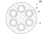
次に、図9に示すように、それぞれの低屈折率領域42内に、ドリルによる穿孔加工により、空孔43を形成する。この穿孔加工では、共通クラッド部となる領域41と低屈折率領域42の屈折率差によって、空孔43は低屈折率領域42の長手方向(第一のガラスロッド40の長手方向)に沿って加工されて行くため、加工曲がりが少ない。
なお、図9には、低屈折率領域42の中央部に空孔43を形成する場合を例示したが、本発明は、これに限定されない。本発明にあっては、低屈折率領域内であれば、空孔を形成する位置は低屈折率領域の中央部でなくてもよい。
このようにして、空孔43の加工曲がりが少ない空孔付きの第一のガラスロッド40Aが得られる。
なお、図9には、低屈折率領域42の中央部に空孔43を形成する場合を例示したが、本発明は、これに限定されない。本発明にあっては、低屈折率領域内であれば、空孔を形成する位置は低屈折率領域の中央部でなくてもよい。
このようにして、空孔43の加工曲がりが少ない空孔付きの第一のガラスロッド40Aが得られる。
次に、コアとなる部分51と、コアとなる部分51の周囲に配置されたクラッドとなる部分52と、を備えた第二のガラスロッド50を6本準備する(図10参照)。
この第二のガラスロッド50では、コアとなる部分51は、共通クラッド部となる領域41の屈折率(第二の屈折率)よりも高い屈折率(第一の屈折率)を有する。また、クラッドとなる部分52は、コアとなる部分51よりも低い屈折率(第四の屈折率)を有する。
この第二のガラスロッド50では、コアとなる部分51は、共通クラッド部となる領域41の屈折率(第二の屈折率)よりも高い屈折率(第一の屈折率)を有する。また、クラッドとなる部分52は、コアとなる部分51よりも低い屈折率(第四の屈折率)を有する。
次に、低屈折率領域42内に形成されたそれぞれの空孔43内に、上記の第二のガラスロッド50を挿入する。
次に、第二のガラスロッド50が挿入された第一のガラスロッド40Aを加熱することによって、第一のガラスロッド40Aと第二のガラスロッド50を一体化して、図10に示すような断面を有するガラス母材60を得る。
得られたガラス母材60には、各第二のガラスロッド50の周囲にフッ素が添加された低屈折率領域42が残っているが、この低屈折率領域42がマルチコア光ファイバのコア間のクロストークを抑制する効果も奏する。
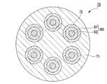
次に、上記の方法で製造されたガラス母材60を線引きすることにより、図11に示すようなマルチコア型の光ファイバ70が得られる。
ガラス母材60を線引きする方法としては、特に限定されるものではなく、公知の方法が用いられる。
線引き後の光ファイバ70は、公知の手法により、各種樹脂で被覆することが好ましい。
ガラス母材60を線引きする方法としては、特に限定されるものではなく、公知の方法が用いられる。
線引き後の光ファイバ70は、公知の手法により、各種樹脂で被覆することが好ましい。
光ファイバ70は、第二の屈折率を有する共通クラッド71と、共通クラッド71内に互いに離隔して配置された複数の光ファイバ導波路80とから概略構成されている。
光ファイバ導波路80は、第二のガラスロッド50と同様の構成を有し、コア81は、共通クラッド71の屈折率(第二の屈折率)よりも高い屈折率(第一の屈折率)を有する。また、クラッド82は、コア81よりも低い屈折率(第四の屈折率)を有する。
光ファイバ導波路80は、第二のガラスロッド50と同様の構成を有し、コア81は、共通クラッド71の屈折率(第二の屈折率)よりも高い屈折率(第一の屈折率)を有する。また、クラッド82は、コア81よりも低い屈折率(第四の屈折率)を有する。
光ファイバ導波路80は、共通クラッド71に対して同心円状に、ほぼ等間隔に6つ設けられている。
また、光ファイバ導波路80の周囲に低屈折率部72が設けられている。
共通クラッド71は石英ガラスから構成され、低屈折率部72はフッ素が添加された石英ガラスから構成されている。
また、光ファイバ導波路80の周囲に低屈折率部72が設けられている。
共通クラッド71は石英ガラスから構成され、低屈折率部72はフッ素が添加された石英ガラスから構成されている。
また、共通クラッド71の屈折率(第二の屈折率)をn2、低屈折率部72の屈折率(第三の屈折率)をn3とすると、n3<n2の関係を満たしている。
本実施形態の光ファイバ70は、空孔43の加工曲がりが少ないガラス母材60を線引きして得られているので、クロストークの劣化が抑制されているから、伝送容量を大幅に向上することができる。
また、本発明の実施形態によれば、上記の加工曲がりの抑制以外にも以下の効果を奏する。
従来、ガラス母材に対してドリルによる穿孔加工を行った後、形成された空孔の内表面の平滑化、加工時に生じたクラックの除去、空孔径の微調整などを目的として、空孔内の研磨やエッチング加工などを行っている。空孔内の研磨やエッチング加工では、空孔の内表面を0.01~0.3mm程度削っている。
本発明の実施形態によれば、ガラス母材における、空孔を形成する領域が、フッ素が添加された低屈折率領域であるので、空孔内の研磨性やエッチング加工性に優れ、より短時間で加工できるといった効果も得られる。
従来、ガラス母材に対してドリルによる穿孔加工を行った後、形成された空孔の内表面の平滑化、加工時に生じたクラックの除去、空孔径の微調整などを目的として、空孔内の研磨やエッチング加工などを行っている。空孔内の研磨やエッチング加工では、空孔の内表面を0.01~0.3mm程度削っている。
本発明の実施形態によれば、ガラス母材における、空孔を形成する領域が、フッ素が添加された低屈折率領域であるので、空孔内の研磨性やエッチング加工性に優れ、より短時間で加工できるといった効果も得られる。
なお、本実施形態では、第一のガラスロッドおよび光ファイバに、空孔が6つ設けられた場合を例示したが、本発明はこれに限定されない。本発明にあっては、空孔の数は、所望の光ファイバの光学特性(クロストーク)に応じて適宜調整される。
(2)第二実施形態
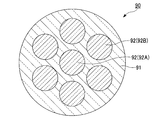
図12に示すように、共通クラッド部となる領域91内に、互いに離隔して配置された複数の低屈折率領域92を備えた第一のガラスロッド90を作製する。
低屈折率領域92は、共通クラッド部となる領域91の中央に設けたれた低屈折率領域92Aと、低屈折率領域92Aの周囲に、共通クラッド部となる領域91に対して同心円状に、ほぼ等間隔に6つ設けられた低屈折率領域92Bと、を備えている。
共通クラッド部となる領域91は石英ガラスから構成され、低屈折率領域92はフッ素が添加された石英ガラスから構成されている。
図12に示すように、共通クラッド部となる領域91内に、互いに離隔して配置された複数の低屈折率領域92を備えた第一のガラスロッド90を作製する。
低屈折率領域92は、共通クラッド部となる領域91の中央に設けたれた低屈折率領域92Aと、低屈折率領域92Aの周囲に、共通クラッド部となる領域91に対して同心円状に、ほぼ等間隔に6つ設けられた低屈折率領域92Bと、を備えている。
共通クラッド部となる領域91は石英ガラスから構成され、低屈折率領域92はフッ素が添加された石英ガラスから構成されている。
また、共通クラッド部となる領域91の屈折率(第二の屈折率)をn12、低屈折率領域92の屈折率(第三の屈折率)をn13とすると、n13<n12の関係を満たしている。
低屈折率領域92において、全周方向にわたって、フッ素添加量は均一であることが好ましい。また、低屈折率領域92において、全周方向にわたって、比屈折率差のばらつきは0.01%未満であることが好ましい。
低屈折率領域92において、全周方向にわたって、フッ素添加量は均一であることが好ましい。また、低屈折率領域92において、全周方向にわたって、比屈折率差のばらつきは0.01%未満であることが好ましい。
このような構造を有する第一のガラスロッド90の製造方法を説明する。
まず、石英ガラス管の内部において、中心にフッ素添加石英ガラスロッド、フッ素添加石英ガラスロッドの周囲に純粋石英ガラスロッド、純粋石英ガラスロッドの周囲にフッ素添加石英ガラスロッド、さらに、フッ素添加石英ガラスロッドの周囲に純粋石英ガラスロッドを配置する。
次に、ガラスロッドが配置された石英ガラス管の一端を封止し、開放している他端から石英ガラス管内を真空引きしながら、その石英ガラス管全体を加熱することにより、石英ガラス管を軟化させて、石英ガラス管内の隙間を埋め、図12に示す構造の第一のガラスロッド90を得る。
まず、石英ガラス管の内部において、中心にフッ素添加石英ガラスロッド、フッ素添加石英ガラスロッドの周囲に純粋石英ガラスロッド、純粋石英ガラスロッドの周囲にフッ素添加石英ガラスロッド、さらに、フッ素添加石英ガラスロッドの周囲に純粋石英ガラスロッドを配置する。
次に、ガラスロッドが配置された石英ガラス管の一端を封止し、開放している他端から石英ガラス管内を真空引きしながら、その石英ガラス管全体を加熱することにより、石英ガラス管を軟化させて、石英ガラス管内の隙間を埋め、図12に示す構造の第一のガラスロッド90を得る。
また、低屈折率領域92の直径、第一のガラスロッド90における低屈折率領域92の配置は、後工程で、それぞれの低屈折率領域92内に形成される空孔に挿入される第二のガラスロッドの直径、および、所望のマルチコア光ファイバの光学特性(クロストーク)に応じて適宜調整される。
次に、図13に示すように、それぞれの低屈折率領域92内において、第二のガラスロッドを挿入する位置に、ドリルによる穿孔加工により、空孔93を形成する。この穿孔加工では、共通クラッド部となる領域91と低屈折率領域92の屈折率差によって、空孔93は低屈折率領域92の長手方向(第一のガラスロッド90の長手方向)に沿って加工されて行くため、加工曲がりが少ない。
このようにして、空孔93の加工曲がりが少ない空孔付きの第一のガラスロッド90Aが得られる。
このようにして、空孔93の加工曲がりが少ない空孔付きの第一のガラスロッド90Aが得られる。
次に、コアとなる部分101と、コアとなる部分101の周囲に配置されたクラッドとなる部分102と、を備えた第二のガラスロッド100を7本準備する(図14参照)。
この第二のガラスロッド100では、コアとなる部分101は、共通クラッド部となる領域91の屈折率(第二の屈折率)よりも高い屈折率(第一の屈折率)を有する。また、クラッドとなる部分102は、コアとなる部分101よりも低い屈折率(第四の屈折率)を有する。
この第二のガラスロッド100では、コアとなる部分101は、共通クラッド部となる領域91の屈折率(第二の屈折率)よりも高い屈折率(第一の屈折率)を有する。また、クラッドとなる部分102は、コアとなる部分101よりも低い屈折率(第四の屈折率)を有する。
次に、低屈折率領域92内に形成されたそれぞれの空孔93内に、上記の第二のガラスロッド100を挿入する。
次に、第二のガラスロッド100が挿入された第一のガラスロッド90Aを加熱することによって、第一のガラスロッド90Aと第二のガラスロッド100を一体化して、図14に示すような断面を有するガラス母材110を得る。
得られたガラス母材110には、各第二のガラスロッド100の周囲にフッ素が添加された低屈折率領域92が残っているが、この低屈折率領域92がマルチコア光ファイバのコア間のクロストークを抑制する効果も奏する。
次に、上記の方法で製造されたガラス母材110を線引きすることにより、図15に示すようなマルチコア型の光ファイバ120が得られる。
ガラス母材110を線引きする方法としては、特に限定されるものではなく、公知の方法が用いられる。
線引き後の光ファイバ120は、公知の手法により、各種樹脂で被覆することが好ましい。
ガラス母材110を線引きする方法としては、特に限定されるものではなく、公知の方法が用いられる。
線引き後の光ファイバ120は、公知の手法により、各種樹脂で被覆することが好ましい。
光ファイバ120は、第二の屈折率を有する共通クラッド121と、共通クラッド121内に互いに離隔して配置された複数の光ファイバ導波路130とから概略構成されている。
光ファイバ導波路130は、第二のガラスロッド100と同様の構成を満たし、コア131は、共通クラッド121の屈折率(第二の屈折率)よりも高い屈折率(第一の屈折率)を有する。また、クラッド132は、コア131よりも低い屈折率(第四の屈折率)を有する。
光ファイバ導波路130は、第二のガラスロッド100と同様の構成を満たし、コア131は、共通クラッド121の屈折率(第二の屈折率)よりも高い屈折率(第一の屈折率)を有する。また、クラッド132は、コア131よりも低い屈折率(第四の屈折率)を有する。
光ファイバ導波路130は、共通クラッド121の中央に1つと、共通クラッド121の周囲を囲み、共通クラッド121に対して同心円状に、ほぼ等間隔に6つとが設けられている。
また、光ファイバ導波路130の周囲に低屈折率部122が設けられている。
共通クラッド121は石英ガラスから構成され、低屈折率部122はフッ素が添加された石英ガラスから構成されている。
また、光ファイバ導波路130の周囲に低屈折率部122が設けられている。
共通クラッド121は石英ガラスから構成され、低屈折率部122はフッ素が添加された石英ガラスから構成されている。
また、共通クラッド121の屈折率(第二の屈折率)をn12、低屈折率部122の屈折率(第三の屈折率)をn13とすると、n13<n12の関係を満たしている。
本実施形態の光ファイバ120は、空孔93の加工曲がりが少ないガラス母材110を線引きして得られているので、クロストークの劣化が抑制されているから、伝送容量を大幅に向上することができる。
(3)第三実施形態
図16に示すように、共通クラッド部となる領域141内に、互いに離隔して配置された複数の低屈折率領域142を備えた第一のガラスロッド140を作製する。
低屈折率領域142は、共通クラッド部となる領域の中央に設けたれた低屈折率領域142Aと、共通クラッド部となる領域141に対して同心円状に、ほぼ等間隔に6つ設けられた低屈折率領域142Bと、低屈折率領域142Bの周囲に、共通クラッド部となる領域141に対して同心円状に、ほぼ等間隔に6つ設けられた低屈折率領域142Cと、を備えている。
共通クラッド部となる領域141は石英ガラスから構成され、低屈折率領域142はフッ素が添加された石英ガラスから構成されている。
図16に示すように、共通クラッド部となる領域141内に、互いに離隔して配置された複数の低屈折率領域142を備えた第一のガラスロッド140を作製する。
低屈折率領域142は、共通クラッド部となる領域の中央に設けたれた低屈折率領域142Aと、共通クラッド部となる領域141に対して同心円状に、ほぼ等間隔に6つ設けられた低屈折率領域142Bと、低屈折率領域142Bの周囲に、共通クラッド部となる領域141に対して同心円状に、ほぼ等間隔に6つ設けられた低屈折率領域142Cと、を備えている。
共通クラッド部となる領域141は石英ガラスから構成され、低屈折率領域142はフッ素が添加された石英ガラスから構成されている。
また、共通クラッド部となる領域141の屈折率(第二の屈折率)をn22、低屈折率領域142の屈折率(第三の屈折率)をn23とすると、n23<n22の関係を満たしている。
低屈折率領域142において、全周方向にわたって、フッ素添加量は均一であることが好ましい。また、低屈折率領域142において、全周方向にわたって、比屈折率差のばらつきは0.01%未満であることが好ましい。
低屈折率領域142において、全周方向にわたって、フッ素添加量は均一であることが好ましい。また、低屈折率領域142において、全周方向にわたって、比屈折率差のばらつきは0.01%未満であることが好ましい。
このような構造を有する第一のガラスロッド140の製造方法を説明する。
まず、石英ガラス管の内部において、中心にフッ素添加石英ガラスロッド、その周囲に純粋石英ガラスロッド、その周囲にフッ素添加石英ガラスロッド、その周囲に純粋石英ガラスロッド、その周囲にフッ素添加石英ガラスロッド、さらに、その周囲に純粋石英ガラスロッドを配置する。
次に、ガラスロッドが配置された石英ガラス管の一端を封止し、開放している他端から石英ガラス管内を真空引きしながら、その石英ガラス管全体を加熱することにより、石英ガラス管を軟化させて、石英ガラス管内の隙間を埋め、図16に示す構造の第一のガラスロッド140を得る。
まず、石英ガラス管の内部において、中心にフッ素添加石英ガラスロッド、その周囲に純粋石英ガラスロッド、その周囲にフッ素添加石英ガラスロッド、その周囲に純粋石英ガラスロッド、その周囲にフッ素添加石英ガラスロッド、さらに、その周囲に純粋石英ガラスロッドを配置する。
次に、ガラスロッドが配置された石英ガラス管の一端を封止し、開放している他端から石英ガラス管内を真空引きしながら、その石英ガラス管全体を加熱することにより、石英ガラス管を軟化させて、石英ガラス管内の隙間を埋め、図16に示す構造の第一のガラスロッド140を得る。
また、低屈折率領域142の直径、第一のガラスロッド140における低屈折率領域142の配置は、後工程で、それぞれの低屈折率領域142内に形成される空孔に挿入される第二のガラスロッドの直径、および、所望のマルチコア光ファイバの光学特性(クロストーク)に応じて適宜調整される。
次に、図17に示すように、それぞれの低屈折率領域142内において、第二のガラスロッドを挿入する位置に、ドリルによる穿孔加工により、空孔143を形成する。この穿孔加工では、共通クラッド部となる領域141と低屈折率領域142の屈折率差によって、空孔143は低屈折率領域142の長手方向(第一のガラスロッド140の長手方向)に沿って加工されて行くため、加工曲がりが少ない。
このようにして、空孔143の加工曲がりが少ない空孔付きの第一のガラスロッド140Aが得られる。
このようにして、空孔143の加工曲がりが少ない空孔付きの第一のガラスロッド140Aが得られる。
次に、コアとなる部分151と、コアとなる部分151の周囲に配置されたクラッドとなる部分152と、を備えた第二のガラスロッド150を13本準備する(図18参照)。
この第二のガラスロッド150では、コアとなる部分151は、共通クラッド部となる領域141の屈折率(第二の屈折率)よりも高い屈折率(第一の屈折率)を有する。また、クラッドとなる部分152は、コアとなる部分151よりも低い屈折率(第四の屈折率)を有する。
この第二のガラスロッド150では、コアとなる部分151は、共通クラッド部となる領域141の屈折率(第二の屈折率)よりも高い屈折率(第一の屈折率)を有する。また、クラッドとなる部分152は、コアとなる部分151よりも低い屈折率(第四の屈折率)を有する。
次に、低屈折率領域142内に形成されたそれぞれの空孔143内に、上記の第二のガラスロッド150を挿入する。
次に、第二のガラスロッド150が挿入された第一のガラスロッド140Aを加熱することによって、第一のガラスロッド140Aと第二のガラスロッド150を一体化して、図18に示すような断面を有するガラス母材160を得る。
得られたガラス母材160には、各第二のガラスロッド150の周囲にフッ素が添加された低屈折率領域142が残っているが、この低屈折率領域142がマルチコア光ファイバのコア間のクロストークを抑制する効果も奏する。
次に、上記の方法で製造されたガラス母材160を線引きすることにより、図19に示すようなマルチコア型の光ファイバ170が得られる。
ガラス母材160を線引きする方法としては、特に限定されるものではなく、公知の方法が用いられる。
線引き後の光ファイバ170は、公知の手法により、各種樹脂で被覆することが好ましい。
ガラス母材160を線引きする方法としては、特に限定されるものではなく、公知の方法が用いられる。
線引き後の光ファイバ170は、公知の手法により、各種樹脂で被覆することが好ましい。
光ファイバ170は、第二の屈折率を有する共通クラッド171と、共通クラッド171内に互いに離隔して配置された複数の光ファイバ導波路180とから概略構成されている。
光ファイバ導波路180は、第二のガラスロッド150と同様の構成を満たし、コア181は、共通クラッド171の屈折率(第二の屈折率)よりも高い屈折率(第一の屈折率)を有する。また、クラッド182は、コア181よりも低い屈折率(第四の屈折率)を有する。
光ファイバ導波路180は、第二のガラスロッド150と同様の構成を満たし、コア181は、共通クラッド171の屈折率(第二の屈折率)よりも高い屈折率(第一の屈折率)を有する。また、クラッド182は、コア181よりも低い屈折率(第四の屈折率)を有する。
光ファイバ導波路180は、共通クラッド171の中央に1つと、その周囲を囲み、共通クラッド171に対して同心円状に、ほぼ等間隔に6つと、その周囲を囲み、共通クラッド171に対して同心円状に、ほぼ等間隔に6つとが設けられている。
また、光ファイバ導波路180の周囲に低屈折率部172が設けられている。
共通クラッド171は石英ガラスから構成され、低屈折率部172はフッ素が添加された石英ガラスから構成されている。
また、光ファイバ導波路180の周囲に低屈折率部172が設けられている。
共通クラッド171は石英ガラスから構成され、低屈折率部172はフッ素が添加された石英ガラスから構成されている。
また、共通クラッド171の屈折率(第二の屈折率)をn22、低屈折率部172の屈折率(第三の屈折率)をn23とすると、n23<n22の関係を満たしている。
本実施形態の光ファイバ170は、空孔143の加工曲がりが少ないガラス母材160を線引きして得られているので、クロストークの劣化が抑制されているから、伝送容量を大幅に向上することができる。
(4)第四実施形態
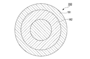
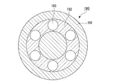
図20に示すように、共通クラッド部となる領域191内に、共通クラッド部となる領域191に対して同心円状に、環状の低屈折率領域192を備えた第一のガラスロッド190を作製する。
共通クラッド部となる領域191は石英ガラスから構成され、低屈折率領域192はフッ素が添加された石英ガラスから構成されている。
図20に示すように、共通クラッド部となる領域191内に、共通クラッド部となる領域191に対して同心円状に、環状の低屈折率領域192を備えた第一のガラスロッド190を作製する。
共通クラッド部となる領域191は石英ガラスから構成され、低屈折率領域192はフッ素が添加された石英ガラスから構成されている。
また、共通クラッド部となる領域191の屈折率(第二の屈折率)をn32、低屈折率領域192の屈折率(第三の屈折率)をn33とすると、n33<n32の関係を満たしている。
低屈折率領域192において、全周方向にわたって、フッ素添加量は均一であることが好ましい。また、低屈折率領域192において、全周方向にわたって、比屈折率差のばらつきは0.01%未満であることが好ましい。
低屈折率領域192において、全周方向にわたって、フッ素添加量は均一であることが好ましい。また、低屈折率領域192において、全周方向にわたって、比屈折率差のばらつきは0.01%未満であることが好ましい。
このような構造を有する第一のガラスロッド190の作製には、VAD(Vapor phase Axial Deposition)法やCVD(chemical vapor deposition)法などの一般的な光ファイバ用プリフォームの製造方法を適用することができる。
また、低屈折率領域192の内径および外径は、後工程で、低屈折率領域192内に形成される空孔に挿入される第二のガラスロッドの直径、および、所望のマルチコア光ファイバの光学特性(クロストーク)に応じて適宜調整される。
次に、図21に示すように、低屈折率領域192内において、第二のガラスロッドを挿入する位置に、ドリルによる穿孔加工により、空孔193を形成する。この穿孔加工では、低屈折率領域192内に、互いに離隔して、共通クラッド部となる領域191に対して同心円状に、ほぼ等間隔に6つの空孔193を形成する。
この穿孔加工では、共通クラッド部となる領域191と低屈折率領域192の屈折率差によって、空孔193は低屈折率領域192の長手方向(第一のガラスロッド190の長手方向)に沿って加工されて行くため、加工曲がりが少ない。
なお、図21には、低屈折率領域192の中央部に空孔193を形成する場合を例示したが、本発明は、これに限定されない。本発明にあっては、低屈折率領域内であれば、空孔を形成する位置は低屈折率領域の中央部でなくてもよい。
このようにして、空孔193の加工曲がりが少ない空孔付きの第一のガラスロッド190Aが得られる。
この穿孔加工では、共通クラッド部となる領域191と低屈折率領域192の屈折率差によって、空孔193は低屈折率領域192の長手方向(第一のガラスロッド190の長手方向)に沿って加工されて行くため、加工曲がりが少ない。
なお、図21には、低屈折率領域192の中央部に空孔193を形成する場合を例示したが、本発明は、これに限定されない。本発明にあっては、低屈折率領域内であれば、空孔を形成する位置は低屈折率領域の中央部でなくてもよい。
このようにして、空孔193の加工曲がりが少ない空孔付きの第一のガラスロッド190Aが得られる。
次に、コアとなる部分201と、コアとなる部分201の周囲に配置されたクラッドとなる部分202と、を備えた第二のガラスロッド200を6本準備する(図22参照)。
この第二のガラスロッド200では、コアとなる部分201は、共通クラッド部となる領域191の屈折率(第二の屈折率)よりも高い屈折率(第一の屈折率)を有する。また、クラッドとなる部分202は、コアとなる部分201よりも低い屈折率(第四の屈折率)を有する。
この第二のガラスロッド200では、コアとなる部分201は、共通クラッド部となる領域191の屈折率(第二の屈折率)よりも高い屈折率(第一の屈折率)を有する。また、クラッドとなる部分202は、コアとなる部分201よりも低い屈折率(第四の屈折率)を有する。
次に、低屈折率領域192内に形成されたそれぞれの空孔193内に、上記の第二のガラスロッド200を挿入する。
次に、第二のガラスロッド200が挿入された第一のガラスロッド190Aを加熱することによって、第一のガラスロッド180Aと第二のガラスロッド200を一体化して、図22に示すような断面を有するガラス母材210を得る。
得られたガラス母材210には、各第二のガラスロッド200の周囲にフッ素が添加された低屈折率領域192が残っているが、この低屈折率領域192がマルチコア光ファイバのコア間のクロストークを抑制する効果も奏する。
次に、上記の方法で製造されたガラス母材210を線引きすることにより、図23に示すようなマルチコア型の光ファイバ220が得られる。
ガラス母材210を線引きする方法としては、特に限定されるものではなく、公知の方法が用いられる。
線引き後の光ファイバ220は、公知の手法により、各種樹脂で被覆することが好ましい。
ガラス母材210を線引きする方法としては、特に限定されるものではなく、公知の方法が用いられる。
線引き後の光ファイバ220は、公知の手法により、各種樹脂で被覆することが好ましい。
光ファイバ220は、第二の屈折率を有する共通クラッド221と、共通クラッド221内に、共通クラッド221に対して同心円状に配置された環状の低屈折率部222と、低屈折率部222内に、互いに離隔して、共通クラッド221に対して同心円状に、ほぼ等間隔に配置された6つの光ファイバ導波路230とから概略構成されている。
光ファイバ導波路230は、第二のガラスロッド200と同様の構成を有し、コア231は、共通クラッド221の屈折率(第二の屈折率)よりも高い屈折率(第一の屈折率)を有する。また、クラッド232は、コア231よりも低い屈折率(第四の屈折率)を有する。
光ファイバ導波路230は、第二のガラスロッド200と同様の構成を有し、コア231は、共通クラッド221の屈折率(第二の屈折率)よりも高い屈折率(第一の屈折率)を有する。また、クラッド232は、コア231よりも低い屈折率(第四の屈折率)を有する。
共通クラッド221は石英ガラスから構成され、低屈折率部222はフッ素が添加された石英ガラスから構成されている。
また、共通クラッド221の屈折率(第二の屈折率)をn32、低屈折率部222の屈折率(第三の屈折率)をn33とすると、n33<n32の関係を満たしている。
本実施形態の光ファイバ220は、空孔193の加工曲がりが少ないガラス母材210を線引きして得られているので、クロストークの劣化が抑制されているから、伝送容量を大幅に向上することができる。
(5)第五実施形態
図24に示すように、共通クラッド部となる領域241内に低屈折率領域242を備えた第一のガラスロッド240を作製する。
低屈折率領域242は、共通クラッド部となる領域241の中央に設けたれた低屈折率領域242Aと、低屈折率領域242Aの周囲に、第一のガラスロッド240(共通クラッド部となる領域241)に対して同心円状に設けられた環状の低屈折率領域242Bと、を備えている。
共通クラッド部となる領域241は石英ガラスから構成され、低屈折率領域242はフッ素が添加された石英ガラスから構成されている。
図24に示すように、共通クラッド部となる領域241内に低屈折率領域242を備えた第一のガラスロッド240を作製する。
低屈折率領域242は、共通クラッド部となる領域241の中央に設けたれた低屈折率領域242Aと、低屈折率領域242Aの周囲に、第一のガラスロッド240(共通クラッド部となる領域241)に対して同心円状に設けられた環状の低屈折率領域242Bと、を備えている。
共通クラッド部となる領域241は石英ガラスから構成され、低屈折率領域242はフッ素が添加された石英ガラスから構成されている。
また、共通クラッド部となる領域241の屈折率(第二の屈折率)をn42、低屈折率領域242の屈折率(第三の屈折率)をn43とすると、n43<n42の関係を満たしている。
低屈折率領域242において、全周方向にわたって、フッ素添加量は均一であることが好ましい。また、低屈折率領域242において、全周方向にわたって、比屈折率差のばらつきは0.01%未満であることが好ましい。
低屈折率領域242において、全周方向にわたって、フッ素添加量は均一であることが好ましい。また、低屈折率領域242において、全周方向にわたって、比屈折率差のばらつきは0.01%未満であることが好ましい。
このような構造を有する第一のガラスロッド240の作製には、VAD(Vapor phase Axial Deposition)法やCVD(chemical vapor deposition)法などの一般的な光ファイバ用プリフォームの製造方法を適用することができる。
また、低屈折率領域242Aの外径、並びに、低屈折率領域242Bの内径および外径は、後工程で、低屈折率領域242内に形成される空孔に挿入される第二のガラスロッドの直径、および、所望のマルチコア光ファイバの光学特性(クロストーク)に応じて適宜調整される。
次に、図25に示すように、低屈折率領域242内において、第二のガラスロッドを挿入する位置に、ドリルによる穿孔加工により、空孔243を形成する。この穿孔加工では、低屈折率領域242A内に1つの空孔243を形成し、低屈折率領域242B内に、互いに離隔して、共通クラッド部となる領域241に対して同心円状に、ほぼ等間隔に6つの空孔243を形成する。
この穿孔加工では、共通クラッド部となる領域241と低屈折率領域242の屈折率差によって、空孔243は低屈折率領域242の長手方向(第一のガラスロッド240の長手方向)に沿って加工されて行くため、加工曲がりが少ない。
このようにして、空孔243の加工曲がりが少ない空孔付きの第一のガラスロッド240Aが得られる。
この穿孔加工では、共通クラッド部となる領域241と低屈折率領域242の屈折率差によって、空孔243は低屈折率領域242の長手方向(第一のガラスロッド240の長手方向)に沿って加工されて行くため、加工曲がりが少ない。
このようにして、空孔243の加工曲がりが少ない空孔付きの第一のガラスロッド240Aが得られる。
次に、コアとなる部分251と、コアとなる部分251の周囲に配置されたクラッドとなる部分252と、を備えた第二のガラスロッド250を7本準備する(図26参照)。
この第二のガラスロッド250では、コアとなる部分251は、共通クラッド部となる領域241の屈折率(第二の屈折率)よりも高い屈折率(第一の屈折率)を有する。また、クラッドとなる部分252は、コアとなる部分251よりも低い屈折率(第四の屈折率)を有する。
この第二のガラスロッド250では、コアとなる部分251は、共通クラッド部となる領域241の屈折率(第二の屈折率)よりも高い屈折率(第一の屈折率)を有する。また、クラッドとなる部分252は、コアとなる部分251よりも低い屈折率(第四の屈折率)を有する。
次に、低屈折率領域242内に形成されたそれぞれの空孔243内に、上記の第二のガラスロッド250を挿入する。
次に、第二のガラスロッド250が挿入された第一のガラスロッド240Aを加熱することによって、第一のガラスロッド240Aと第二のガラスロッド250を一体化して、図26に示すような断面を有するガラス母材260を得る。
得られたガラス母材260には、各第二のガラスロッド250の周囲にフッ素が添加された低屈折率領域242が残っているが、この低屈折率領域242がマルチコア光ファイバのコア間のクロストークを抑制する効果も奏する。
次に、上記の方法で製造されたガラス母材260を線引きすることにより、図27に示すようなマルチコア型の光ファイバ270が得られる。
ガラス母材260を線引きする方法としては、特に限定されるものではなく、公知の方法が用いられる。
線引き後の光ファイバ270は、公知の手法により、各種樹脂で被覆することが好ましい。
ガラス母材260を線引きする方法としては、特に限定されるものではなく、公知の方法が用いられる。
線引き後の光ファイバ270は、公知の手法により、各種樹脂で被覆することが好ましい。
光ファイバ270は、第二の屈折率を有する共通クラッド271と、共通クラッド271の中央に配置された低屈折率部272(272A)と、低屈折率部272(272A)内に配置された1つの光ファイバ導波路280と、共通クラッド271内に、共通クラッド271に対して同心円状に配置された環状の低屈折率部272(272B)と、低屈折率部262(262B)内に、互いに離隔して、共通クラッド261に対して同心円状に、ほぼ等間隔に配置された6つの光ファイバ導波路280とから概略構成されている。
光ファイバ導波路280は、第二のガラスロッド250と同様の構成を有し、コア281は、共通クラッド271の屈折率(第二の屈折率)よりも高い屈折率(第一の屈折率)を有する。また、クラッド282は、コア281よりも低い屈折率(第四の屈折率)を有する。
光ファイバ導波路280は、第二のガラスロッド250と同様の構成を有し、コア281は、共通クラッド271の屈折率(第二の屈折率)よりも高い屈折率(第一の屈折率)を有する。また、クラッド282は、コア281よりも低い屈折率(第四の屈折率)を有する。
共通クラッド271は石英ガラスから構成され、低屈折率部272はフッ素が添加された石英ガラスから構成されている。
また、共通クラッド271の屈折率(第二の屈折率)をn42、低屈折率部272の屈折率(第三の屈折率)をn43とすると、n43<n42の関係を満たしている。
本実施形態の光ファイバ270は、空孔243の加工曲がりが少ないガラス母材260を線引きして得られているので、クロストークの劣化が抑制されているから、伝送容量を大幅に向上することができる。
(6)第六実施形態
図28に示すように、共通クラッド部となる領域291内に低屈折率領域292を備えた第一のガラスロッド290を作製する。
低屈折率領域292は、共通クラッド部となる領域の中央に設けたれた低屈折率領域292Aと、低屈折率領域292Aの周囲に、共通クラッド部となる領域281に対して同心円状に設けられた環状の低屈折率領域292Bと、低屈折率領域292Bの周囲に、共通クラッド部となる領域291に対して同心円状に設けられた環状の低屈折率領域292Cと、を備えている。
共通クラッド部となる領域291は石英ガラスから構成され、低屈折率領域292はフッ素が添加された石英ガラスから構成されている。
図28に示すように、共通クラッド部となる領域291内に低屈折率領域292を備えた第一のガラスロッド290を作製する。
低屈折率領域292は、共通クラッド部となる領域の中央に設けたれた低屈折率領域292Aと、低屈折率領域292Aの周囲に、共通クラッド部となる領域281に対して同心円状に設けられた環状の低屈折率領域292Bと、低屈折率領域292Bの周囲に、共通クラッド部となる領域291に対して同心円状に設けられた環状の低屈折率領域292Cと、を備えている。
共通クラッド部となる領域291は石英ガラスから構成され、低屈折率領域292はフッ素が添加された石英ガラスから構成されている。
また、共通クラッド部となる領域291の屈折率(第二の屈折率)をn52、低屈折率領域292の屈折率(第三の屈折率)をn53とすると、n53<n52の関係を満たしている。
低屈折率領域292において、全周方向にわたって、フッ素添加量は均一であることが好ましい。また、低屈折率領域292において、全周方向にわたって、比屈折率差のばらつきは0.01%未満であることが好ましい。
低屈折率領域292において、全周方向にわたって、フッ素添加量は均一であることが好ましい。また、低屈折率領域292において、全周方向にわたって、比屈折率差のばらつきは0.01%未満であることが好ましい。
このような構造を有する第一のガラスロッド290の作製には、VAD(Vapor phase Axial Deposition)法やCVD(chemical vapor deposition)法などの一般的な光ファイバ用プリフォームの製造方法を適用することができる。
また、低屈折率領域292Aの外径、低屈折率領域292Bの内径および外径、並びに、低屈折率領域292Cの内径および外径は、後工程で、低屈折率領域292内に形成される空孔に挿入される第二のガラスロッドの直径、および、所望のマルチコア光ファイバの光学特性(クロストーク)に応じて適宜調整される。
次に、図29に示すように、低屈折率領域292内において、第二のガラスロッドを挿入する位置に、ドリルによる穿孔加工により、空孔293を形成する。この穿孔加工では、低屈折率領域292A内に1つの空孔293を形成する。また、低屈折率領域292B内に、互いに離隔して、共通クラッド部となる領域291に対して同心円状に、ほぼ等間隔に6つの空孔293を形成する。さらに、低屈折率領域292C内に、互いに離隔して、共通クラッド部となる領域291に対して同心円状に、ほぼ等間隔に6つの空孔293を形成する。
この穿孔加工では、共通クラッド部となる領域291と低屈折率領域292の屈折率差によって、空孔293は低屈折率領域292の長手方向(第一のガラスロッド290の長手方向)に沿って加工されて行くため、加工曲がりが少ない。
このようにして、空孔293の加工曲がりが少ない空孔付きの第一のガラスロッド290Aが得られる。
この穿孔加工では、共通クラッド部となる領域291と低屈折率領域292の屈折率差によって、空孔293は低屈折率領域292の長手方向(第一のガラスロッド290の長手方向)に沿って加工されて行くため、加工曲がりが少ない。
このようにして、空孔293の加工曲がりが少ない空孔付きの第一のガラスロッド290Aが得られる。
次に、コアとなる部分301と、コアとなる部分301の周囲に配置されたクラッドとなる部分302と、を備えた第二のガラスロッド300を13本準備する(図30参照)。
この第二のガラスロッド300では、コアとなる部分301は、クラッドとなる部分302の屈折率(第二の屈折率)よりも高い屈折率(第一の屈折率)を有する。また、クラッドとなる部分302は、コアとなる部分301よりも低い屈折率(第四の屈折率)を有する。
この第二のガラスロッド300では、コアとなる部分301は、クラッドとなる部分302の屈折率(第二の屈折率)よりも高い屈折率(第一の屈折率)を有する。また、クラッドとなる部分302は、コアとなる部分301よりも低い屈折率(第四の屈折率)を有する。
次に、低屈折率領域292内に形成されたそれぞれの空孔293内に、上記の第二のガラスロッド300を挿入する。
次に、第二のガラスロッド300が挿入された第一のガラスロッド290Aを加熱することによって、第一のガラスロッド290Aと第二のガラスロッド300を一体化して、図30に示すような断面を有するガラス母材310を得る。
得られたガラス母材310には、各第二のガラスロッド300の周囲にフッ素が添加された低屈折率領域292が残っているが、この低屈折率領域292がマルチコア光ファイバのコア間のクロストークを抑制する効果も奏する。
次に、上記の方法で製造されたガラス母材310を線引きすることにより、図31に示すようなマルチコア型の光ファイバ320が得られる。
ガラス母材310を線引きする方法としては、特に限定されるものではなく、公知の方法が用いられる。
線引き後の光ファイバ320は、公知の手法により、各種樹脂で被覆することが好ましい。
ガラス母材310を線引きする方法としては、特に限定されるものではなく、公知の方法が用いられる。
線引き後の光ファイバ320は、公知の手法により、各種樹脂で被覆することが好ましい。
光ファイバ320は、第二の屈折率を有する共通クラッド321と、共通クラッド321の中央に配置された低屈折率部322A(322)と、低屈折率部322A(322)内に配置された1つの光ファイバ導波路330と、共通クラッド321内において、低屈折率部322A(322)の周囲に、共通クラッド321に対して同心円状に配置された環状の低屈折率部322B(322)と、低屈折率部322B(322)内に、互いに離隔して、共通クラッド321に対して同心円状に配置された6つの光ファイバ導波路330と、共通クラッド321内において、低屈折率部322B(322)の周囲に、共通クラッド321に対して同心円状に配置された環状の低屈折率部322C(322)と、低屈折率部322C(322)内に、互いに離隔して、共通クラッド321に対して同心円状に配置された6つの光ファイバ導波路330とから概略構成されている。
光ファイバ導波路330は、第二のガラスロッド300と同様の構成を有し、コア331は、共通クラッド321の屈折率(第二の屈折率)よりも高い屈折率(第一の屈折率)を有する。また、クラッド332は、コア331よりも低い屈折率(第四の屈折率)を有する。
光ファイバ導波路330は、第二のガラスロッド300と同様の構成を有し、コア331は、共通クラッド321の屈折率(第二の屈折率)よりも高い屈折率(第一の屈折率)を有する。また、クラッド332は、コア331よりも低い屈折率(第四の屈折率)を有する。
共通クラッド321は石英ガラスから構成され、低屈折率部322はフッ素が添加された石英ガラスから構成されている。
また、共通クラッド321の屈折率(第二の屈折率)をn52、低屈折率部322の屈折率(第三の屈折率)をn53とすると、n53<n52の関係を満たしている。
本実施形態の光ファイバ320は、空孔293の加工曲がりが少ないガラス母材310を線引きして得られているので、クロストークの劣化が抑制されているから、伝送容量を大幅に向上することができる。
以上、本発明の好ましい実施形態を説明し、上記で説明してきたが、これらは本発明の例示的なものであり、限定するものとして考慮されるべきではないことを理解すべきである。追加、省略、置換、およびその他の変更は、本発明の範囲から逸脱することなく行うことができる。従って、本発明は、前述の説明によって限定されていると見なされるべきではなく、特許請求の範囲によって制限されている。
以下、実施例および比較例により本発明をさらに具体的に説明するが、本発明は以下の実施例に限定されない。
[実施例1]
図12に示すように、共通クラッド部となる領域91内に、互いに離隔して配置された複数の低屈折率領域92を備えた第一のガラスロッド90を作製した。
低屈折率領域92は、共通クラッド部となる領域91の中央に設けたれた低屈折率領域92Aと、低屈折率領域92Aの周囲に、共通クラッド部となる領域81に対して同心円状に、ほぼ等間隔に6つ設けられた低屈折率領域92Bと、を備えている。
共通クラッド部となる領域91は石英ガラスから構成され、低屈折率領域92はフッ素が添加された石英ガラスから構成されている。
第一のガラスロッド90の外径は100mm、長さは1000mmであった。また、低屈折率領域92の外径は19mmであった。
また、共通クラッド部となる領域91の屈折率(第二の屈折率)をn12、低屈折率領域92の屈折率(第三の屈折率)をn13とすると、n13<n12の関係を満たしていた。さらに、低屈折率領域92の比屈折率差は0.7%であった。
図12に示すように、共通クラッド部となる領域91内に、互いに離隔して配置された複数の低屈折率領域92を備えた第一のガラスロッド90を作製した。
低屈折率領域92は、共通クラッド部となる領域91の中央に設けたれた低屈折率領域92Aと、低屈折率領域92Aの周囲に、共通クラッド部となる領域81に対して同心円状に、ほぼ等間隔に6つ設けられた低屈折率領域92Bと、を備えている。
共通クラッド部となる領域91は石英ガラスから構成され、低屈折率領域92はフッ素が添加された石英ガラスから構成されている。
第一のガラスロッド90の外径は100mm、長さは1000mmであった。また、低屈折率領域92の外径は19mmであった。
また、共通クラッド部となる領域91の屈折率(第二の屈折率)をn12、低屈折率領域92の屈折率(第三の屈折率)をn13とすると、n13<n12の関係を満たしていた。さらに、低屈折率領域92の比屈折率差は0.7%であった。
次に、図13に示すように、それぞれの低屈折率領域92内において、第二のガラスロッドを挿入する位置に、ドリルによる穿孔加工により、空孔93を形成した。
このとき、ドリルツールの先端の外径を18mmとし、穿孔加工による加工長を1000mmとし、第一のガラスロッド90の長手方向に沿って貫通孔を形成し、空孔付きの第一のガラスロッド90Aを得た。
次に、コアとなる部分101と、コアとなる部分101の周囲に配置されたクラッドとなる部分102と、を備えた第二のガラスロッド100を7本準備した(図14参照)。
次に、低屈折率領域92内に形成されたそれぞれの空孔93内に、上記の第二のガラスロッド100を挿入した。
次に、第二のガラスロッド100が挿入された第一のガラスロッド90Aを加熱することによって、第一のガラスロッド90Aと第二のガラスロッド100を一体化して、図14に示すような断面を有するガラス母材110を得た。
このとき、ドリルツールの先端の外径を18mmとし、穿孔加工による加工長を1000mmとし、第一のガラスロッド90の長手方向に沿って貫通孔を形成し、空孔付きの第一のガラスロッド90Aを得た。
次に、コアとなる部分101と、コアとなる部分101の周囲に配置されたクラッドとなる部分102と、を備えた第二のガラスロッド100を7本準備した(図14参照)。
次に、低屈折率領域92内に形成されたそれぞれの空孔93内に、上記の第二のガラスロッド100を挿入した。
次に、第二のガラスロッド100が挿入された第一のガラスロッド90Aを加熱することによって、第一のガラスロッド90Aと第二のガラスロッド100を一体化して、図14に示すような断面を有するガラス母材110を得た。
次に、上記の方法で製造されたガラス母材110を線引きすることにより、図15に示すような外径140μmのマルチコア型の光ファイバ120を得た。
光ファイバ120は、第二の屈折率を有する共通クラッド121と、共通クラッド121内に互いに離隔して配置された複数の光ファイバ導波路130とから概略構成されている。
光ファイバ導波路130は、共通クラッド121の中央に1つと、その周囲を囲み、共通クラッド121に対して同心円状に、ほぼ等間隔に6つとが設けられている。
光ファイバ導波路130は、コア131が、共通クラッド121の屈折率(第二の屈折率)よりも高い屈折率(第一の屈折率)を有する。また、クラッド132が、コア131よりも低い屈折率(第四の屈折率)を有する。
また、光ファイバ導波路130の周囲に低屈折率部122が設けられている。
また、共通クラッド121の屈折率(第二の屈折率)をn12、低屈折率部122の屈折率(第三の屈折率)をn13とすると、n13<n12の関係を満たしていた。
光ファイバ120は、第二の屈折率を有する共通クラッド121と、共通クラッド121内に互いに離隔して配置された複数の光ファイバ導波路130とから概略構成されている。
光ファイバ導波路130は、共通クラッド121の中央に1つと、その周囲を囲み、共通クラッド121に対して同心円状に、ほぼ等間隔に6つとが設けられている。
光ファイバ導波路130は、コア131が、共通クラッド121の屈折率(第二の屈折率)よりも高い屈折率(第一の屈折率)を有する。また、クラッド132が、コア131よりも低い屈折率(第四の屈折率)を有する。
また、光ファイバ導波路130の周囲に低屈折率部122が設けられている。
また、共通クラッド121の屈折率(第二の屈折率)をn12、低屈折率部122の屈折率(第三の屈折率)をn13とすると、n13<n12の関係を満たしていた。
[実施例2]
図24に示すように、共通クラッド部となる領域241内に低屈折率領域242を備えた第一のガラスロッド240を作製した。
低屈折率領域242は、共通クラッド部となる領域241の中央に設けたれた低屈折率領域242Aと、低屈折率領域242Aの周囲に、共通クラッド部となる領域241に対して同心円状に設けられた環状の低屈折率領域242Bと、を備えている。
共通クラッド部となる領域241は石英ガラスから構成され、低屈折率領域242はフッ素が添加された石英ガラスから構成されている。
共通クラッド部となる領域241の外径は100mm、長さは1000mmであった。
また、低屈折率領域242の厚さは19mmであった。
また、共通クラッド部となる領域241の屈折率(第二の屈折率)をn42、低屈折率領域242の屈折率(第三の屈折率)をn43とすると、n43<n42の関係を満たしていた。さらに、低屈折率領域242の比屈折率差は0.7%であった。
図24に示すように、共通クラッド部となる領域241内に低屈折率領域242を備えた第一のガラスロッド240を作製した。
低屈折率領域242は、共通クラッド部となる領域241の中央に設けたれた低屈折率領域242Aと、低屈折率領域242Aの周囲に、共通クラッド部となる領域241に対して同心円状に設けられた環状の低屈折率領域242Bと、を備えている。
共通クラッド部となる領域241は石英ガラスから構成され、低屈折率領域242はフッ素が添加された石英ガラスから構成されている。
共通クラッド部となる領域241の外径は100mm、長さは1000mmであった。
また、低屈折率領域242の厚さは19mmであった。
また、共通クラッド部となる領域241の屈折率(第二の屈折率)をn42、低屈折率領域242の屈折率(第三の屈折率)をn43とすると、n43<n42の関係を満たしていた。さらに、低屈折率領域242の比屈折率差は0.7%であった。
次に、図25に示すように、低屈折率領域242内において、第二のガラスロッドを挿入する位置に、ドリルによる穿孔加工により、空孔243を形成した。この穿孔加工では、低屈折率領域242A内に1つの空孔243を形成し、低屈折率領域242B内に、互いに離隔して、共通クラッド部となる領域241に対して同心円状に、ほぼ等間隔に6つの空孔243を形成した。
このとき、ドリルツールの先端の外径を18mmとし、穿孔加工による加工長を1000mmとし、第一のガラスロッド240の長手方向に沿って貫通孔を形成し、空孔付きの第一のガラスロッド240Aを得た。
次に、コアとなる部分251と、コアとなる部分251の周囲に配置されたクラッドとなる部分252と、を備えた第二のガラスロッド250を7本準備した(図26参照)。
次に、低屈折率領域242内に形成されたそれぞれの空孔243内に、上記の第二のガラスロッド250を挿入した。
次に、第二のガラスロッド250が挿入された第一のガラスロッド240Aを加熱することによって、第一のガラスロッド240Aと第二のガラスロッド250を一体化して、図26に示すような断面を有するガラス母材260を得た。
このとき、ドリルツールの先端の外径を18mmとし、穿孔加工による加工長を1000mmとし、第一のガラスロッド240の長手方向に沿って貫通孔を形成し、空孔付きの第一のガラスロッド240Aを得た。
次に、コアとなる部分251と、コアとなる部分251の周囲に配置されたクラッドとなる部分252と、を備えた第二のガラスロッド250を7本準備した(図26参照)。
次に、低屈折率領域242内に形成されたそれぞれの空孔243内に、上記の第二のガラスロッド250を挿入した。
次に、第二のガラスロッド250が挿入された第一のガラスロッド240Aを加熱することによって、第一のガラスロッド240Aと第二のガラスロッド250を一体化して、図26に示すような断面を有するガラス母材260を得た。
次に、上記の方法で製造されたガラス母材260を線引きすることにより、図27に示すような外径140μmのマルチコア型の光ファイバ270を得た。
光ファイバ270は、第二の屈折率を有する共通クラッド271と、共通クラッド271の中央に配置された低屈折率部272(272A)と、低屈折率部272(272A)内に配置された1つの光ファイバ導波路280と、共通クラッド271内に、共通クラッド271に対して同心円状に配置された環状の低屈折率部272(272B)と、低屈折率部272(272B)内に、互いに離隔して、共通クラッド271に対して同心円状に、ほぼ等間隔に配置された6つの光ファイバ導波路280とから概略構成されている。
光ファイバ導波路280は、コア281が、共通クラッド271の屈折率(第二の屈折率)よりも高い屈折率(第一の屈折率)を有する。また、クラッド282が、コア281よりも低い屈折率(第四の屈折率)を有する。
また、光ファイバ導波路280の周囲に低屈折率部272が設けられている。
また、共通クラッド271の屈折率(第二の屈折率)をn42、低屈折率部272の屈折率(第三の屈折率)をn43とすると、n43<n42の関係を満たしていた。
光ファイバ270は、第二の屈折率を有する共通クラッド271と、共通クラッド271の中央に配置された低屈折率部272(272A)と、低屈折率部272(272A)内に配置された1つの光ファイバ導波路280と、共通クラッド271内に、共通クラッド271に対して同心円状に配置された環状の低屈折率部272(272B)と、低屈折率部272(272B)内に、互いに離隔して、共通クラッド271に対して同心円状に、ほぼ等間隔に配置された6つの光ファイバ導波路280とから概略構成されている。
光ファイバ導波路280は、コア281が、共通クラッド271の屈折率(第二の屈折率)よりも高い屈折率(第一の屈折率)を有する。また、クラッド282が、コア281よりも低い屈折率(第四の屈折率)を有する。
また、光ファイバ導波路280の周囲に低屈折率部272が設けられている。
また、共通クラッド271の屈折率(第二の屈折率)をn42、低屈折率部272の屈折率(第三の屈折率)をn43とすると、n43<n42の関係を満たしていた。
[比較例]
図32に示すように、共通クラッド部となる領域341と、領域341の中央に、コアとなる部分351、コアとなる部分351の周囲に配置されたクラッドとなる部分352、および、部分352の周囲に配置されたフッ素が添加された低屈折率部353を備えた第二のガラスロッド350とを有する第一のガラスロッド340を作製した。
第一のガラスロッド340の外径は100mm、長さは1000mmであった。
また、共通クラッド部となる領域341の屈折率をn102、低屈折率部353の屈折率をn103とすると、n103<n102の関係を満たしていた。
図32に示すように、共通クラッド部となる領域341と、領域341の中央に、コアとなる部分351、コアとなる部分351の周囲に配置されたクラッドとなる部分352、および、部分352の周囲に配置されたフッ素が添加された低屈折率部353を備えた第二のガラスロッド350とを有する第一のガラスロッド340を作製した。
第一のガラスロッド340の外径は100mm、長さは1000mmであった。
また、共通クラッド部となる領域341の屈折率をn102、低屈折率部353の屈折率をn103とすると、n103<n102の関係を満たしていた。
次に、図33に示すように、共通クラッド部となる領域341において、コア材を挿入する位置(ここでは、低屈折率部353の周囲)に、ドリルによる穿孔加工により、共通クラッド部となる領域341に対して同心円状に、ほぼ等間隔に6つの空孔342を形成した。
このとき、ドリルツールの先端の外径を18mmとし、穿孔加工による加工長を1000mmとし、第一のガラスロッド340の長手方向に沿って貫通孔を形成し、空孔付きの第一のガラスロッド340Aを得た。
次に、コアとなる部分351、コアとなる部分351の周囲に配置されたクラッドとなる部分352、および、その周囲に配置されたフッ素が添加された低屈折率部353を備えた第二のガラスロッド350を6本準備した(図34参照)。
次に、共通クラッド部となる領域341内に形成されたそれぞれの空孔332内に、上記の第二のガラスロッド350を挿入した。
次に、第二のガラスロッド350が挿入された第一のガラスロッド340Aを加熱することによって、第一のガラスロッド340Aと第二のガラスロッド350を一体化して、図34に示すような断面を有するガラス母材360を得た。
このとき、ドリルツールの先端の外径を18mmとし、穿孔加工による加工長を1000mmとし、第一のガラスロッド340の長手方向に沿って貫通孔を形成し、空孔付きの第一のガラスロッド340Aを得た。
次に、コアとなる部分351、コアとなる部分351の周囲に配置されたクラッドとなる部分352、および、その周囲に配置されたフッ素が添加された低屈折率部353を備えた第二のガラスロッド350を6本準備した(図34参照)。
次に、共通クラッド部となる領域341内に形成されたそれぞれの空孔332内に、上記の第二のガラスロッド350を挿入した。
次に、第二のガラスロッド350が挿入された第一のガラスロッド340Aを加熱することによって、第一のガラスロッド340Aと第二のガラスロッド350を一体化して、図34に示すような断面を有するガラス母材360を得た。
次に、上記の方法で製造されたガラス母材360を線引きすることにより、図35に示すような外径140μmのマルチコア型の光ファイバ370を得た。
光ファイバ370は、共通クラッド371と、共通クラッド371の中央に配置された光ファイバ導波路380と、共通クラッド371内において、中央に配置された光ファイバ導波路380の周囲に、互いに離隔して、共通クラッド371に対して同心円状に配置された6つの光ファイバ導波路380とから概略構成されている。
光ファイバ導波路380は、コア371と、コア371の周囲に配置されたクラッド372と、クラッド372の周囲に配置されたフッ素が添加された低屈折率領部373とから構成されている。
また、クラッド361の屈折率をn102、低屈折率領部373の屈折率をn103とすると、n103<n102の関係を満たしていた。
光ファイバ370は、共通クラッド371と、共通クラッド371の中央に配置された光ファイバ導波路380と、共通クラッド371内において、中央に配置された光ファイバ導波路380の周囲に、互いに離隔して、共通クラッド371に対して同心円状に配置された6つの光ファイバ導波路380とから概略構成されている。
光ファイバ導波路380は、コア371と、コア371の周囲に配置されたクラッド372と、クラッド372の周囲に配置されたフッ素が添加された低屈折率領部373とから構成されている。
また、クラッド361の屈折率をn102、低屈折率領部373の屈折率をn103とすると、n103<n102の関係を満たしていた。
[評価]
実施例1および2と比較例について、以下の3つの方法により、加工曲がり量の評価を行った。
(1)空孔付きの第一のガラスロッドの空孔位置の計測による加工曲がり量の評価
実施例1および2と比較例の第一のガラスロッドに穿孔加工を行った後、図36に示すように、第一のガラスロッド390の加工開始端面391と加工終了端面392において、空孔393の位置を計測した。
ここで、加工開始端面391において、第一のガラスロッド390の中心(コア394の中心)から、6つの空孔393の中心までの距離をそれぞれRs1、Rs2、Rs3、Rs4、Rs5、Rs6と定義し、距離Rs1~Rs6を計測した。そして、これらの距離Rs1~Rs6の平均値を加工開始端面391における空孔位置Rsと定義した。
同様に、加工終了端面392において、第一のガラスロッド390の中心(コア394の中心)から、6つの空孔393の中心までの距離をそれぞれRe1、Re2、Re3、Re4、Re5、Re6と定義し、距離Re1~Re6を計測した。そして、これらの距離Re1~Re6の平均値を加工終了端面392における空孔位置Reと定義した。
そして、第一のガラスロッド390における加工曲がり量ΔRを|Rs-Re|と定義した。即ち、加工曲がり量ΔRを「Rs-Re」の絶対値と定義した。結果を表1に示す。
実施例1および2と比較例について、以下の3つの方法により、加工曲がり量の評価を行った。
(1)空孔付きの第一のガラスロッドの空孔位置の計測による加工曲がり量の評価
実施例1および2と比較例の第一のガラスロッドに穿孔加工を行った後、図36に示すように、第一のガラスロッド390の加工開始端面391と加工終了端面392において、空孔393の位置を計測した。
ここで、加工開始端面391において、第一のガラスロッド390の中心(コア394の中心)から、6つの空孔393の中心までの距離をそれぞれRs1、Rs2、Rs3、Rs4、Rs5、Rs6と定義し、距離Rs1~Rs6を計測した。そして、これらの距離Rs1~Rs6の平均値を加工開始端面391における空孔位置Rsと定義した。
同様に、加工終了端面392において、第一のガラスロッド390の中心(コア394の中心)から、6つの空孔393の中心までの距離をそれぞれRe1、Re2、Re3、Re4、Re5、Re6と定義し、距離Re1~Re6を計測した。そして、これらの距離Re1~Re6の平均値を加工終了端面392における空孔位置Reと定義した。
そして、第一のガラスロッド390における加工曲がり量ΔRを|Rs-Re|と定義した。即ち、加工曲がり量ΔRを「Rs-Re」の絶対値と定義した。結果を表1に示す。
(2)光ファイバのコアの位置の計測による加工曲がり量の評価
実施例1および2と比較例で得られた光ファイバについて、図37に示すように、上記の加工開始端面に相当する端面と加工終了端面に相当する端面において、光学顕微鏡により、コア間の距離を計測した。
加工開始端面に相当する端面において、中央のコア401の中心から、6つの外側にあるコア402の中心までの距離をそれぞれΛs1、Λs2、Λs3、Λs4、Λs5、Λs6と定義し、距離Λs1~Λs6を計測した。そして、これらの距離Λs1~Λs6の平均値を加工開始端面に相当する端面におけるコア間距離Λsと定義した。
同様に、加工終了端面に相当する端面において、中央のコア401の中心から、6つの外側コア402の中心までの距離をそれぞれΛe1、Λe2、Λe3、Λe4、Λe5、Λe6と定義し、距離Λe1~Λe6を計測した。そして、これらの距離Λe1~Λe6の平均値を加工終了端面に相当する端面におけるコア間距離Λeと定義した。
そして、光ファイバ400における加工曲がり量ΔΛを|Λs-Λe|と定義した。即ち、加工曲がり量ΔΛを「Λs-Λe」の絶対値と定義した。結果を表1に示す。
実施例1および2と比較例で得られた光ファイバについて、図37に示すように、上記の加工開始端面に相当する端面と加工終了端面に相当する端面において、光学顕微鏡により、コア間の距離を計測した。
加工開始端面に相当する端面において、中央のコア401の中心から、6つの外側にあるコア402の中心までの距離をそれぞれΛs1、Λs2、Λs3、Λs4、Λs5、Λs6と定義し、距離Λs1~Λs6を計測した。そして、これらの距離Λs1~Λs6の平均値を加工開始端面に相当する端面におけるコア間距離Λsと定義した。
同様に、加工終了端面に相当する端面において、中央のコア401の中心から、6つの外側コア402の中心までの距離をそれぞれΛe1、Λe2、Λe3、Λe4、Λe5、Λe6と定義し、距離Λe1~Λe6を計測した。そして、これらの距離Λe1~Λe6の平均値を加工終了端面に相当する端面におけるコア間距離Λeと定義した。
そして、光ファイバ400における加工曲がり量ΔΛを|Λs-Λe|と定義した。即ち、加工曲がり量ΔΛを「Λs-Λe」の絶対値と定義した。結果を表1に示す。
(3)光ファイバのクロストークの評価
実施例1および2と比較例で得られた光ファイバについて、以下示す方法によりクロストークを測定した。
光源から、光ファイバの一端面(第1端面)において、いずれかのコア(例えば、中央に設けられたコア)に光を入射させ、光ファイバの他端面において、光を入射したコア(例えば、中央に設けられたコア)から出力した光の強度を測定する。
また、光ファイバの他端面(第1端面とは反対側の第2端面)において、光を入射したコアとは異なるコア(例えば、中央に設けられたコアの周囲を囲むように設けられたコア)から出力した光の強度を測定する。
そして、光を入射したコア(例えば、中央に設けられたコア)から出力した光の強度と、光を入射したコアとは異なるコア(例えば、中央に設けられたコアの周囲を囲むように設けられたコア)から出力した光の強度との比率から、クロストーク値を算出する。
結果を表1に示す。
実施例1および2と比較例で得られた光ファイバについて、以下示す方法によりクロストークを測定した。
光源から、光ファイバの一端面(第1端面)において、いずれかのコア(例えば、中央に設けられたコア)に光を入射させ、光ファイバの他端面において、光を入射したコア(例えば、中央に設けられたコア)から出力した光の強度を測定する。
また、光ファイバの他端面(第1端面とは反対側の第2端面)において、光を入射したコアとは異なるコア(例えば、中央に設けられたコアの周囲を囲むように設けられたコア)から出力した光の強度を測定する。
そして、光を入射したコア(例えば、中央に設けられたコア)から出力した光の強度と、光を入射したコアとは異なるコア(例えば、中央に設けられたコアの周囲を囲むように設けられたコア)から出力した光の強度との比率から、クロストーク値を算出する。
結果を表1に示す。
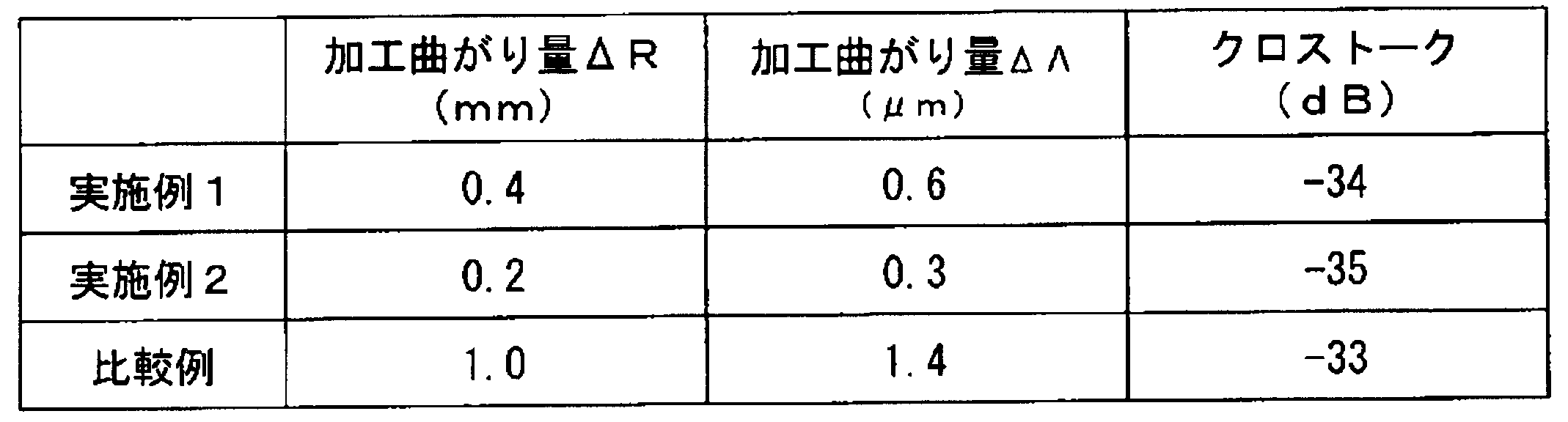
表1の結果から、実施例1および2は、比較例に比べて、加工曲がりが小さいことが分かった。これにより、本発明は、加工曲がりの抑制に有効であることが確認された。
なお、加工曲がり量ΔΛが大きい程、コア間距離が近付くことを示しているとともに、コア間クロストークが劣化することを意味している。したがって、加工曲がりが大きい比較例では、加工曲がり量ΔΛが大きくなっており、その結果、クロストークが劣化していることが分かる。
なお、加工曲がり量ΔΛが大きい程、コア間距離が近付くことを示しているとともに、コア間クロストークが劣化することを意味している。したがって、加工曲がりが大きい比較例では、加工曲がり量ΔΛが大きくなっており、その結果、クロストークが劣化していることが分かる。
1・・・高屈折率コア、2・・・内側クラッド、3・・・低屈折率クラッド、4・・・外側クラッド、21・・・石英ガラス部、22・・・フッ素添加石英ガラス部、23・・・加工面、31・・・純シリカコア、32・・・フッ素添加クラッド、33・・・低屈折率フッ素添加クラッド、40・・・第一のガラスロッド、41・・・共通クラッド部となる領域、42・・・低屈折率領域、43・・・空孔、50・・・第二のガラスロッド、51・・・コアとなる部分、52・・・クラッドとなる部分、60・・・ガラス母材、70・・・光ファイバ、71・・・共通クラッド、72・・・低屈折率部、80・・・光ファイバ導波路、81・・・コア、82・・・クラッド、190・・・第一のガラスロッド、191・・・共通クラッド部となる領域、192・・・低屈折率領域、193・・・空孔、200・・・第二のガラスロッド、201・・・コアとなる部分、202・・・クラッドとなる部分、210・・・ガラス母材、220・・・光ファイバ、221・・・共通クラッド、222・・・低屈折率部、230・・・光ファイバ導波路、231・・・コア、232・・・クラッド。
Claims (9)
- 複数のコアを有する光ファイバの製造方法であって、
第二の屈折率を有する共通クラッド部となる領域内に互いに離隔して配置された複数の低屈折率領域を備え、前記低屈折率領域にはフッ素が添加され、かつ、前記第二の屈折率よりも低い第三の屈折率を有する第一のガラスロッドを準備し、
前記複数の低屈折率領域のそれぞれの内部に空孔を形成し、
前記第二の屈折率よりも高い第一の屈折率を有するコアとなる部分と、前記コアとなる部分の周囲に配置され、前記第一の屈折率よりも低い第四の屈折率を有するクラッドとなる部分と、を備えた第二のガラスロッドを複数準備し、
前記複数の低屈折率領域内に形成されたそれぞれの空孔内に前記第二のガラスロッドを挿入し、
前記第一のガラスロッドと前記第二のガラスロッドとを一体化してガラス母材を作製し、
前記ガラス母材を線引きする線引きする光ファイバの製造方法。 - 複数のコアを有する光ファイバの製造方法であって、
第二の屈折率を有する共通クラッド部となる領域内に環状の低屈折率領域を備え、前記低屈折率領域にはフッ素が添加され、かつ、前記第二の屈折率よりも低い第三の屈折率を有する第一のガラスロッドを準備し、
前記低屈折率領域内に、互いに離隔する複数の空孔を形成し、
前記第二の屈折率よりも高い第一の屈折率を有するコアとなる部分と、前記コアとなる部分の周囲に配置され、前記第一の屈折率よりも低い第四の屈折率を有するクラッドとなる部分と、を備えた第二のガラスロッドを複数準備し、
前記低屈折率領域内に形成されたそれぞれの空孔内に前記第二のガラスロッドを挿入し、
前記第一のガラスロッドと前記第二のガラスロッドとを一体化してガラス母材を作製し、
前記ガラス母材を線引きする線引きする光ファイバの製造方法。 - 前記第一のガラスロッドを準備する際に、前記共通クラッド部となる領域の中央に前記低屈折率領域を設け、
前記空孔を形成する際に、前記共通クラッド部となる領域に形成された前記低屈折率領域内に空孔を形成する請求項2に記載の光ファイバの製造方法。 - 前記第一のガラスロッドを準備する際に、前記共通クラッド部となる領域に、同心円状に前記低屈折率領域を複数設ける請求項2又は請求項3に記載の光ファイバの製造方法。
- 前記ガラス母材の作製と、前記線引きとを同時に行う請求項1から請求項4のいずれか一項に記載の光ファイバの製造方法。
- 複数のコアを有する光ファイバであって、
第二の屈折率を有する共通クラッドと、
前記第二の屈折率よりも高い第一の屈折率を有するコアと、前記コアの周囲に配置されて前記第四の屈折率を有するクラッドとを備えるとともに、前記共通クラッド内に互いに離隔して配置された複数の光ファイバ導波路と、
前記光ファイバ導波路の周囲に設けられ、フッ素が添加され、前記第二の屈折率よりも低い第三の屈折率を有する低屈折率部と
を含む光ファイバ。 - 複数のコアを有する光ファイバであって、
第二の屈折率を有する共通クラッドと、
前記第二の屈折率よりも低い第三の屈折率を有するとともに、フッ素が添加され、前記共通クラッド内に設けられた環状の低屈折率部と、
前記第二の屈折率よりも高い第一の屈折率を有するコアと、前記コアの周囲に配置されて前記第四の屈折率を有するクラッドとを備えるとともに、前記低屈折率部内に互いに離隔して配置された複数の光ファイバ導波路と、
を含む光ファイバ。 - 前記共通クラッドの中央に、前記光ファイバ導波路が設けられ、当該光ファイバ導波路の周囲に前記低屈折率部が設けられた請求項7に記載の光ファイバ。
- 前記共通クラッド内に、同心円状に前記低屈折率部が複数設けられた請求項7又は請求項8に記載の光ファイバ。
Applications Claiming Priority (2)
| Application Number | Priority Date | Filing Date | Title |
|---|---|---|---|
| JP2012-192595 | 2012-08-31 | ||
| JP2012192595A JP5702344B2 (ja) | 2012-08-31 | 2012-08-31 | 光ファイバおよびその製造方法 |
Publications (1)
| Publication Number | Publication Date |
|---|---|
| WO2014034810A1 true WO2014034810A1 (ja) | 2014-03-06 |
Family
ID=50183615
Family Applications (1)
| Application Number | Title | Priority Date | Filing Date |
|---|---|---|---|
| PCT/JP2013/073221 Ceased WO2014034810A1 (ja) | 2012-08-31 | 2013-08-29 | 光ファイバおよび光ファイバの製造方法 |
Country Status (2)
| Country | Link |
|---|---|
| JP (1) | JP5702344B2 (ja) |
| WO (1) | WO2014034810A1 (ja) |
Cited By (2)
| Publication number | Priority date | Publication date | Assignee | Title |
|---|---|---|---|---|
| CN109283613A (zh) * | 2018-11-26 | 2019-01-29 | 北京交通大学 | 一种低芯间串扰多芯光纤 |
| CN113461324A (zh) * | 2020-03-30 | 2021-10-01 | 住友电气工业株式会社 | 多芯光纤的预制件的制造方法以及多芯光纤的制造方法 |
Families Citing this family (3)
| Publication number | Priority date | Publication date | Assignee | Title |
|---|---|---|---|---|
| JP6859796B2 (ja) * | 2017-03-28 | 2021-04-14 | 住友電気工業株式会社 | 結合型マルチコア光ファイバの製造方法 |
| WO2023090174A1 (ja) * | 2021-11-17 | 2023-05-25 | 古河電気工業株式会社 | マルチコアファイバおよびその製造方法 |
| JP2023135785A (ja) * | 2022-03-16 | 2023-09-29 | 古河電気工業株式会社 | マルチコアファイバ |
Citations (5)
| Publication number | Priority date | Publication date | Assignee | Title |
|---|---|---|---|---|
| WO2010082656A1 (ja) * | 2009-01-19 | 2010-07-22 | 住友電気工業株式会社 | マルチコア光ファイバ |
| JP2011168464A (ja) * | 2010-02-22 | 2011-09-01 | Sumitomo Electric Ind Ltd | マルチコア光ファイバ用母材製造方法 |
| JP2012181282A (ja) * | 2011-02-28 | 2012-09-20 | Fujikura Ltd | マルチコアファイバ |
| JP2012203035A (ja) * | 2011-03-23 | 2012-10-22 | Mitsubishi Cable Ind Ltd | マルチコアファイバおよびその製造方法 |
| JP5245019B2 (ja) * | 2011-03-02 | 2013-07-24 | 株式会社フジクラ | マルチコアファイバ |
-
2012
- 2012-08-31 JP JP2012192595A patent/JP5702344B2/ja active Active
-
2013
- 2013-08-29 WO PCT/JP2013/073221 patent/WO2014034810A1/ja not_active Ceased
Patent Citations (5)
| Publication number | Priority date | Publication date | Assignee | Title |
|---|---|---|---|---|
| WO2010082656A1 (ja) * | 2009-01-19 | 2010-07-22 | 住友電気工業株式会社 | マルチコア光ファイバ |
| JP2011168464A (ja) * | 2010-02-22 | 2011-09-01 | Sumitomo Electric Ind Ltd | マルチコア光ファイバ用母材製造方法 |
| JP2012181282A (ja) * | 2011-02-28 | 2012-09-20 | Fujikura Ltd | マルチコアファイバ |
| JP5245019B2 (ja) * | 2011-03-02 | 2013-07-24 | 株式会社フジクラ | マルチコアファイバ |
| JP2012203035A (ja) * | 2011-03-23 | 2012-10-22 | Mitsubishi Cable Ind Ltd | マルチコアファイバおよびその製造方法 |
Cited By (3)
| Publication number | Priority date | Publication date | Assignee | Title |
|---|---|---|---|---|
| CN109283613A (zh) * | 2018-11-26 | 2019-01-29 | 北京交通大学 | 一种低芯间串扰多芯光纤 |
| CN113461324A (zh) * | 2020-03-30 | 2021-10-01 | 住友电气工业株式会社 | 多芯光纤的预制件的制造方法以及多芯光纤的制造方法 |
| CN113461324B (zh) * | 2020-03-30 | 2024-05-28 | 住友电气工业株式会社 | 多芯光纤的预制件的制造方法以及多芯光纤的制造方法 |
Also Published As
| Publication number | Publication date |
|---|---|
| JP2014047116A (ja) | 2014-03-17 |
| JP5702344B2 (ja) | 2015-04-15 |
Similar Documents
| Publication | Publication Date | Title |
|---|---|---|
| KR101908735B1 (ko) | 단일 모드 광 섬유 | |
| JP5702344B2 (ja) | 光ファイバおよびその製造方法 | |
| CN115136046B (zh) | 多芯光纤、多芯光纤带、多芯光纤的制造方法及处理方法 | |
| CN1537083A (zh) | 包括含氟区的光波导产品 | |
| JP6268758B2 (ja) | 光ファイバ | |
| JP2015099210A (ja) | マルチコアファイバ及びそのマルチコアファイバの製造方法 | |
| US9599769B2 (en) | Hydrogen-resistant optical fiber | |
| WO2015079987A1 (ja) | 光ファイバ及び光ファイバ母材 | |
| JP6151310B2 (ja) | 光ファイバ用母材の製造方法、及び、光ファイバの製造方法 | |
| JP4383377B2 (ja) | 微細構造光ファイバの作製方法 | |
| JP2015099211A (ja) | マルチコアファイバ | |
| WO2019146750A1 (ja) | マルチコアファイバ及びその製造方法 | |
| JP6966311B2 (ja) | マルチコア光ファイバ母材の製造方法、及び、マルチコア光ファイバの製造方法 | |
| CN108181683A (zh) | 一种低串扰大模场面积多芯光纤及其制备方法 | |
| JP2020019680A (ja) | マルチコアファイバ用母材の製造方法およびマルチコアファイバの製造方法 | |
| US20180282200A1 (en) | Method of manufacturing coupled-core multi-core fiber | |
| WO2013140688A1 (ja) | 光ファイバの製造方法 | |
| JP2023135785A (ja) | マルチコアファイバ | |
| JP5735468B2 (ja) | 光ファイバおよびその製造方法、光ファイバ母材の製造方法 | |
| WO2022050190A1 (ja) | 光ファイバ母材の製造方法及び光ファイバ母材 | |
| WO2018138736A2 (en) | Optical fiber draw assembly and fabricated optical fiber thereof | |
| CN116097141A (zh) | 多芯光纤 | |
| JP5835823B1 (ja) | マルチコア光ファイバ母材の製造方法 | |
| JP6068880B2 (ja) | 光ファイバおよびその製造方法 | |
| WO2011001850A1 (ja) | フォトニックバンドギャップファイバ用母材の製造方法、及び、フォトニックバンドギャップファイバの製造方法 |
Legal Events
| Date | Code | Title | Description |
|---|---|---|---|
| 121 | Ep: the epo has been informed by wipo that ep was designated in this application |
Ref document number: 13832898 Country of ref document: EP Kind code of ref document: A1 |
|
| NENP | Non-entry into the national phase |
Ref country code: DE |
|
| 122 | Ep: pct application non-entry in european phase |
Ref document number: 13832898 Country of ref document: EP Kind code of ref document: A1 |