WO2014034598A1 - 絶縁スクリーンを用いた静電印刷装置および静電印刷方法 - Google Patents
絶縁スクリーンを用いた静電印刷装置および静電印刷方法 Download PDFInfo
- Publication number
- WO2014034598A1 WO2014034598A1 PCT/JP2013/072701 JP2013072701W WO2014034598A1 WO 2014034598 A1 WO2014034598 A1 WO 2014034598A1 JP 2013072701 W JP2013072701 W JP 2013072701W WO 2014034598 A1 WO2014034598 A1 WO 2014034598A1
- Authority
- WO
- WIPO (PCT)
- Prior art keywords
- screen
- powder
- electrode
- electrostatic printing
- electrostatic
- Prior art date
- Legal status (The legal status is an assumption and is not a legal conclusion. Google has not performed a legal analysis and makes no representation as to the accuracy of the status listed.)
- Ceased
Links
Images


Classifications
-
- G—PHYSICS
- G03—PHOTOGRAPHY; CINEMATOGRAPHY; ANALOGOUS TECHNIQUES USING WAVES OTHER THAN OPTICAL WAVES; ELECTROGRAPHY; HOLOGRAPHY
- G03G—ELECTROGRAPHY; ELECTROPHOTOGRAPHY; MAGNETOGRAPHY
- G03G15/00—Apparatus for electrographic processes using a charge pattern
- G03G15/22—Apparatus for electrographic processes using a charge pattern involving the combination of more than one step according to groups G03G13/02 - G03G13/20
-
- B—PERFORMING OPERATIONS; TRANSPORTING
- B41—PRINTING; LINING MACHINES; TYPEWRITERS; STAMPS
- B41J—TYPEWRITERS; SELECTIVE PRINTING MECHANISMS, i.e. MECHANISMS PRINTING OTHERWISE THAN FROM A FORME; CORRECTION OF TYPOGRAPHICAL ERRORS
- B41J2/00—Typewriters or selective printing mechanisms characterised by the printing or marking process for which they are designed
- B41J2/385—Typewriters or selective printing mechanisms characterised by the printing or marking process for which they are designed characterised by selective supply of electric current or selective application of magnetism to a printing or impression-transfer material
- B41J2/41—Typewriters or selective printing mechanisms characterised by the printing or marking process for which they are designed characterised by selective supply of electric current or selective application of magnetism to a printing or impression-transfer material for electrostatic printing
- B41J2/415—Typewriters or selective printing mechanisms characterised by the printing or marking process for which they are designed characterised by selective supply of electric current or selective application of magnetism to a printing or impression-transfer material for electrostatic printing by passing charged particles through a hole or a slit
Definitions
- the present invention relates to an electrostatic printing apparatus and an electrostatic printing method in which powder such as functional powder or edible powder is attached to an object by electrostatic force, and in particular, to an electrostatic printing apparatus using a screen made of an insulating material And the electrostatic printing method.
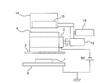
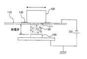
- FIG. 16 is a schematic view showing a conventional electrostatic screen printing apparatus.
- the electrostatic screen printing apparatus includes a stencil screen 110 disposed above the object (substrate) 100 and a rubbing brush 120 on the screen 110.
- Print patterns such as characters and figures are formed on the screen 110 by the mesh net 111.
- As the rubbing brush 120 a soft continuous foam urethane sponge is adopted because of the good rubbing property of the powder to the screen 110.
- the powder 130 is frictionally charged by rubbing the powder 130 onto the screen 110 by the rubbing brush 120, and the powder 130 is further pushed downward through the mesh net 111 of the screen 110.
- a high DC voltage is applied between the object 100 and the screen 110 by a DC power supply DC, and an electrostatic field is formed between the object 100 and the screen 110.
- the powder charged through the mesh network 111 adheres to the surface of the object 100 in a static electric field straight ahead toward the object 100 serving as a counter electrode. In this manner, a print pattern such as characters and graphics on the screen 110 is printed on the surface of the object 100.
- Such electrostatic screen printing techniques are used in a wide range of fields from confectionery to industrial products because uniform films made of powder can be formed on an object.
- the electrostatic screen printing apparatus is required to move the screen 110 away from the object 100 to some extent, as shown in FIG. This is because when the screen 110 is brought into contact with the object 100 or brought very close to the object 100, electricity flows between the screen 110 and the object 100 and no electrostatic field is formed between them. . However, when the object 100 and the screen 110 are separated, the outline of the print shape formed on the object 100 may be slightly blurred.
- one aspect of the present invention is an electrostatic printing apparatus for adhering powder to an object by electrostatic force, which is disposed between an electrode, the electrode and the object A screen, charging means for charging the powder on the screen, and a voltage application device for applying a voltage between the electrode and the object, the screen being formed of an insulating material It is characterized by
- a preferred embodiment of the present invention is characterized in that the screen is a mesh screen.
- a preferred embodiment of the present invention is characterized in that the mesh screen is formed of synthetic fibers.
- a preferred embodiment of the present invention is characterized in that the charging means is a rubbing member for rubbing the powder into the screen.
- a preferred embodiment of the present invention is characterized in that the electrode and the rubbing member are integrally formed.
- a preferred embodiment of the present invention is characterized in that the electrode and the rubbing member are formed of the same conductive material.
- a preferred aspect of the present invention is characterized in that the rubbing member is a rotatable cylindrical roller.
- a preferred embodiment of the present invention is characterized in that the electrode is disposed at the center of the roller.
- a preferred embodiment of the present invention further comprises a relative movement mechanism for relatively moving the roller and the screen in a state where the roller is in contact with the screen.
- a preferred embodiment of the present invention further comprises a hopper for feeding the powder onto the screen.
- a preferred embodiment of the present invention is characterized in that the charging means is a screen vibrating mechanism for vibrating the screen.
- an electrostatic printing apparatus for adhering powder to an object by electrostatic force, comprising: an electrode; a screen disposed between the electrode and the object; And a voltage application device for applying a voltage between the electrode and the object, wherein the screen is formed of an insulating material.
- a preferred embodiment of the present invention is characterized in that the screen is a mesh screen.
- a preferred embodiment of the present invention is characterized in that the mesh screen is formed of synthetic fibers.
- a preferred embodiment of the present invention further comprises a screen vibrating mechanism for vibrating the screen.
- Still another aspect of the present invention is an electrostatic printing method in which powder is attached to an object by electrostatic force, and a voltage is applied between the electrode and the object to form an electrostatic field, and the electrode The powder is frictionally charged on a screen made of an insulating material and disposed between the and the object to cause the powder to adhere to the object by electrostatic force.
- Still another aspect of the present invention is an electrostatic printing method in which powder is attached to an object by electrostatic force, and a voltage is applied between the electrode and the object to form an electrostatic field, and the electrode And charging the powder charged on a screen made of an insulating material, which is disposed between the and the object, and causing the powder to adhere to the object by electrostatic force.
- a preferred embodiment of the present invention is characterized in that the screen is a mesh screen.
- a preferred embodiment of the present invention is characterized in that the powder is a functional powder.
- a preferred embodiment of the present invention is characterized in that the object is an industrial product.
- the electrostatic printing technique according to the present invention is a technique for forming an electrostatic field between an electrode and an object without applying a voltage to a screen and adhering powder to the object using electrostatic force. According to the present invention, the following excellent effects can be obtained. (1) Since the screen is made of an insulating material, the screen can be placed in contact with or very close to the object. As a result, a clear pattern of the contour can be drawn on the object. (2) Since the screen can be brought into close proximity to the object, the thickness of the film made of powder deposited on the object can be controlled by the distance between the screen and the object. (3) As shown in FIG. 16, in the conventional electrostatic screen printing apparatus, an electrostatic field is formed between the lower surface of the screen 110 and the object 100.
- the charged powder 130 In order to apply an electrostatic force to the powder 130, the charged powder 130 needs to be rubbed in and pushed out into an electrostatic field by the brush 120. For this reason, an elastic body such as a sponge is used as the rubbing brush 120.
- the screen is placed in an electrostatic field, and the electrostatic field is formed not only below the screen but also above and inside (the holes through which the powder passes). There is no need to push the body down the screen.
- the powder passing through the screen may adhere to the lower surface of the screen without progressing toward the object.
- the powder is less likely to adhere to the lower surface of the screen than the conventional electrostatic screen printing apparatus.
- the screen is made of an insulating material and / or that electrostatic force acts on the powder even in the holes of the screen.
- materials other than metal, such as resin can be used as the material of the screen. Therefore, the electrostatic printing technology according to the present invention can meet such a demand.
- the screen is not metal
- powder which is not desirable to be in contact with metal for example, powder which easily reacts with metal
- the charge of the powder may change from negative to positive (or positive to negative) due to the influence of the charge of the object.
- the charge of the powder 130 in contact with the object 100 changes from negative to positive
- the powder 130 is attracted to the screen 110 and returns to the screen 110 against gravity.
- the strength of the electrostatic field is inversely proportional to the distance between the electrode and the object. Therefore, the electrostatic force acting on the powder can be weakened by increasing the distance between the electrode and the object.
- the distance between the electrode and the object it is possible to change the distance between the electrode and the object while maintaining the distance between the screen and the object, and vice versa. For example, it is possible to increase the distance between the electrode and the object while extremely shortening the distance between the screen and the object. Therefore, it is possible to prevent the above-described powder return while realizing clear printing. (7) Since the distance between the electrode and the object can be increased, discharge does not occur between the electrode and the object. Therefore, easily flammable powder can be used. In addition, electrostatic printing can be performed even in an easily flammable atmosphere. (8) The electrostatic printing technique according to the present invention can deposit powder on a target with a uniform thickness, as in the conventional electrostatic screen printing technique. Furthermore, it is also possible to form a multilayer film structure by repeatedly depositing different types of powders on the object.
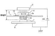
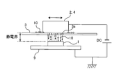
- FIG. 1 is a schematic view showing an embodiment of an electrostatic printing apparatus according to the present invention. It is a figure which shows the example to which the electrode was earth
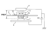
- FIG. It is a side view of the electrostatic printing apparatus shown in FIG. It is a schematic diagram which shows another modification of embodiment shown in FIG. It is a schematic diagram which shows the further another embodiment of this invention. It is a schematic diagram which shows the further another embodiment of this invention. It is a schematic diagram which shows the further another embodiment of this invention. It is a schematic diagram which shows the conventional electrostatic screen printing apparatus.
- the electrostatic printing apparatus according to the present invention is an electrostatic printing apparatus using an insulating screen, unlike the conventional electrostatic screen printing apparatus.
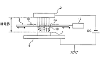
- FIG. 1 is a schematic view showing an embodiment of an electrostatic printing apparatus according to the present invention.
- the electrostatic printing apparatus includes an electrode 2 made of a conductive material such as metal, a screen 3 disposed between the electrode 2 and the object 1, and a rubbing member 4 for rubbing the powder 10 into the screen 3.
- a DC power source DC as a voltage application device for applying a DC voltage between the electrode 2 and the object 1.
- Examples of the object 1 include industrial products and confectionery.
- the screen 3 is horizontally supported by a support (not shown).
- the screen 3 is an insulating screen made of an insulating material.
- the screen 3 is made of a synthetic resin.
- the screen 3 is formed with a plurality of holes 3 a which allow the powder 10 to pass through.
- the plurality of holes 3a are arranged in accordance with a predetermined printing pattern. It is preferable to use a mesh screen as the screen 3. In this case, the print pattern is configured by a mesh.
- the mesh screen can be composed of synthetic fibers such as nylon or polyester.
- mesh screens made of nylon have the advantage of being less expensive or easier to manufacture than conventional stainless steel mesh screens.
- the rubbing member 4 is disposed on the screen 3.
- Various materials can be used for the rubbing member 4 such as elastic materials such as sponge and rubber, and hard materials such as wood and cured resin.
- the rubbing member 4 is a charging unit that generates frictional charge by rubbing the powder 10 into the screen 3 and charges the powder 10 on the screen 3.
- the object 1 is placed on the stage 9, and the stage 9 is connected to the positive electrode of the DC power supply DC and grounded. As shown in FIG. 2, the electrode 2 may be grounded in consideration of workability and safety.
- the electrode 2 is disposed above the object 1 on the stage 9 and spaced apart from the object 1.
- the electrode 2 is connected to the negative electrode of the DC power supply DC.
- a DC voltage for example, 5000 V
- an electrostatic field is formed between the electrode 2 and the object 1.
- the screen 3 is located in this electrostatic field. Since the screen 3 is made of an insulating material, no voltage is applied to the screen 3 and the screen 3 is electrically isolated.
- the powder 10 is supplied to the upper surface of the screen 3. A voltage is applied between the electrode 2 and the object 1 to form an electrostatic field therebetween. While the powder 10 is present between the rubbing member 4 and the screen 3, the rubbing member 4 is rubbed against the screen 3. As a result, the powder 10 is negatively charged by frictional charging and is further rubbed into the screen 3. Since the triboelectric charging of the powder 10 takes place in an electrostatic field, an electrostatic force acts on the charged powder 10. Therefore, the powder 10 travels toward the object 1 through the holes 3 a formed in the screen 3. The powder 10 adheres to the object 1 in accordance with a printing pattern composed of a plurality of holes 3 a formed in the screen 3.
- the powder may be positively charged when it is rubbed into the screen 3 by the rubbing member 4.
- the electrode 2 is connected to the positive electrode of the DC power supply DC
- the stage 9 is connected to the negative electrode of the DC power supply DC.
- the rubbing member 4 may be in sliding contact with the screen 3 manually, or may be in sliding contact with the screen 3 by a drive mechanism. Alternatively, the position of the rubbing member 4 may be fixed, and the screen 3 may be moved relative to the rubbing member 4. Even in this case, the rubbing member 4 can rub the powder 10 into the screen 3.
- the screen 3 is placed in an electrostatic field, and the powder 10 is charged in the electrostatic field. Since the electrostatic field is formed not only below the screen 3 but also above and inside (the holes 3a through which the powder passes), there is no need to push the powder 10 below the screen 3. Therefore, it is not necessary to use an elastic body as the rubbing member 4.
- the material of the rubbing member 4 is not particularly limited as long as it is a material capable of causing frictional electrification of powder.
- the screen 3 can be brought into contact with or extremely close to the object 1.
- the screen 3 it is also possible to place the screen 3 in contact with the object 1. According to such an arrangement, it is possible to print on the object 1 a clear pattern or a very thin linear pattern.
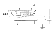
- FIG. 4 is an enlarged view schematically showing the screen 3 in contact with the object 1.
- the screen 3 is a mesh screen composed of a mesh net 7 and a pattern layer 8.
- the mesh net 7 is made of synthetic fibers such as nylon and polyester, and the pattern layer 8 is made of resin.
- the pattern layer 8 is formed on the lower surface of the mesh net 7.
- a printing pattern 8a is formed on the pattern layer 8, and the powder 10 rubbed into the screen 3 reaches the object 1 through the mesh net 7 and the printing pattern 8a, and a printing pattern along the printing pattern 8a Are formed on the object 1.
- the thickness of the printed pattern (for example, figures and characters) formed from the powder 10 on the object 1 is determined depending on the thickness of the pattern layer 8 Be done. For example, if the thickness of the print pattern formed on the object 1 is 80 ⁇ m, the screen 3 having the pattern layer 8 with a thickness of 80 ⁇ m is used. Thus, the thickness of the pattern can be controlled by the thickness of the pattern layer 8.
- an electrode moving mechanism 6 connected to the electrode 2 may be provided, and the electrode 2 may be moved parallel to the screen 3 by the electrode moving mechanism 6. According to such a configuration, printing can be performed on a larger object 1. Furthermore, the electrode 2 can be made smaller.
- the electrode moving mechanism 6 is constituted of, for example, a combination of a belt connected to the electrode 2 and a motor for driving the belt, or a combination of a ball screw and a servomotor.
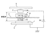
- FIG. 6 is a schematic view showing another embodiment of the present invention.
- the electrode 2 and the rubbing member 4 are integrally configured. More specifically, the electrode 2 is fixed to the upper surface of the rubbing member 4. When the powder 10 is scraped into the screen 3, the scraping member 4 moves integrally with the electrode 2.
- FIG. 7 is a schematic view showing still another embodiment of the present invention.
- the electrode 2 and the rubbing member 4 are made of the same conductive material, and the electrode 2 and the rubbing member 4 are provided as a single member.
- the electrode 2 and the rubbing member 4 are elements having different functions, the rubbing member 4 can also function as the electrode 2 by using a conductive material for the rubbing member 4.
- conductive resin, carbon or the like can be used.
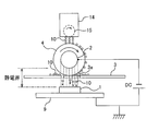
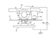
- FIG. 8 is a schematic view showing still another embodiment of the present invention.
- the configurations and operations which are not particularly described are the same as those of the above-described embodiment, and thus the description thereof will be omitted.
- a cylindrical roller is used as the rubbing member 4.
- the roller (sliding-in member) 4 is disposed such that its axial center is parallel to the screen 3, and the outer peripheral surface of the roller 4 is in contact with the upper surface of the screen 3.
- FIG. 9 is a side view of the electrostatic printing apparatus shown in FIG. As shown in FIG. 9, the roller 4 is connected to a motor 12, and the roller 4 is rotated about its axis by the motor 12, and the outer peripheral surface of the roller 4 is in sliding contact with the upper surface of the screen 3.
- the roller 4 is preferably formed of an elastic material such as urethane sponge or rubber.
- the electrode 2 is configured as a support shaft of the roller 4.
- the electrode 2 is disposed at the center of the roller 4, and the roller 4 is configured to rotate around the electrode 2.
- the electrode (support shaft) 2 is connected to a DC power supply DC. Therefore, an electrostatic field is formed between the electrode 2 and the object 1. As can be seen from FIG. 8, the lower part of the roller 4 located below the electrode 2 is placed in an electrostatic field.
- a hopper 14 for supplying the powder 10 to the outer peripheral surface of the roller 4 is disposed above the roller 4, a hopper 14 for supplying the powder 10 to the outer peripheral surface of the roller 4 is disposed.
- the powder 10 is stored inside the hopper 14.
- a plurality of holes (not shown) for allowing the passage of powder are formed, and a rotating brush 15 is disposed to cover these holes.
- the supply amount of the powder 10 can be controlled by the rotational speed of the rotating brush 15.
- the powder 10 is conveyed to the upper surface of the screen 3 by the rotation of the roller 4. Then, the powder 10 is rubbed into the screen 3 by the rotating roller 4 and charged by friction.
- the charged powder 10 travels toward the object 1 by electrostatic force and adheres to the object 1.
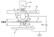
- FIG. 10 is a schematic view showing a modification of the embodiment shown in FIG. 8, and FIG. 11 is a side view of the electrostatic printing apparatus shown in FIG.
- a relative movement mechanism 16 for moving the roller 4 relative to the screen 3 is provided.
- the relative movement mechanism 16 moves the roller 4 parallel to the screen 3 in the direction indicated by the arrow while the roller 4 is in contact with the upper surface of the screen 3.
- the moving direction of the roller 4 is a direction perpendicular to the axial center of the roller 4.
- the hopper 14 is also connected to the relative movement mechanism 16, and the roller 4 and the hopper 14 are integrally moved by the relative movement mechanism 16.
- the roller 4 rubs the powder 10 onto the screen 3 while moving on the screen 3.
- the powder 10 can be attached to a larger area on the object 1.
- the relative movement mechanism 16 is constituted of, for example, a combination of a belt connected to the motor 12 and the hopper 14 and a motor for driving the belt, or a combination of a ball screw and a servomotor.
- the relative movement mechanism 16 shown in FIGS. 10 and 11 moves the roller 4 and the hopper 14, as another example, the relative movement mechanism 16 moves the screen 3 horizontally relative to the roller 4 and the hopper 14. You may Even in this case, the roller (sliding member) 4 and the screen 3 can move relative to each other while maintaining the contact state, and the roller 4 can rub the powder 10 into the screen 3.
- FIG. 12 is a schematic view showing another modified example of the embodiment shown in FIG.
- the configuration of this example is basically the same as the configuration shown in FIG. 10, but differs from the above-described example in that the hopper 14 is disposed side by side with the roller 4. More specifically, the hopper 14 is disposed forward with respect to the traveling direction of the roller 4 indicated by the arrow. The hopper 14 supplies the powder 10 directly to the upper surface of the screen 3, and the roller 4 rubs the powder 10 on the screen 3 into the screen 3.
- the hopper 14 is moved by the relative moving mechanism 16 in synchronization with the roller 4, but a hopper moving mechanism may be provided to move the hopper 14 independently of the roller 4.
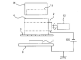
- FIG. 13 is a schematic view showing still another embodiment of the present invention.
- a screen vibrating mechanism 17 is provided instead of the rubbing member 4 as charging means for charging the powder 10 on the screen 3.
- the screen vibrating mechanism 17 causes the powder 10 on the screen 3 to be frictionally charged by vibrating the screen 3 in the horizontal direction.
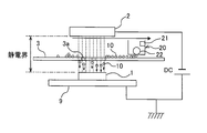
- FIG. 14 is a schematic view showing still another embodiment of the present invention.
- a powder distribution mechanism 20 is provided above the screen 3 in place of the rubbing member 4.
- the powder spraying mechanism 20 stores powder inside.
- the powder distribution mechanism 20 has a charging device 21 such as a corona discharge device, and can charge the powder stored inside.
- a plurality of holes (not shown) which allow the passage of the powder are formed, and the rotating brush 22 is disposed so as to cover the holes. By rotating the rotating brush 22, the powder stored inside the powder distribution mechanism 20 is supplied onto the screen 3 through the holes.
- the powder distribution mechanism 20 is movable in parallel with the screen 3.
- the powder distribution mechanism 20 supplies charged powder 10 onto the screen 3 while moving in parallel with the screen 3.
- the powder 10 on the screen 3 travels toward the object 1 through the holes 3 a of the screen 3 by the action of electrostatic force and adheres to the object 1.
- the powder may be supplied onto the screen 3 by the powder distribution mechanism 20, or the powder may be screen 3 by the powder distribution mechanism 20.
- a voltage may be applied between the electrode 2 and the object 1.
- the screen vibration mechanism 17 described above may be incorporated into the present embodiment.
- the electrode 2 may be moved parallel to the screen 3 while applying a voltage between the electrode 2 and the object 1.
- FIG. 15 is a schematic view showing still another embodiment of the present invention.
- the electrode 2 is covered by the insulating member 25.
- An example of the insulating member 25 is an insulating film having a thickness of about 1 mm.
- the insulating member 25 covers a horizontal surface (bottom surface) facing the screen 3 of the electrode 2 and a side surface connected to the horizontal surface.
- the screen 3 is made of an insulating material, the screen 3 can be placed in contact with or very close to the object 1. As a result, a clear pattern of the contour can be drawn on the object 1.
- the screen 3 can be brought extremely close to the object 1, the thickness of the film made of the powder deposited on the object 1 can be controlled by the distance between the screen 3 and the object 1 Can.
- an electrostatic field is formed between the lower surface of the screen 110 and the object 100. In order to apply electrostatic force to the powder 130, it is necessary to slide the charged powder 130 into the static electric field by the brush 120.
- the screen 3 is placed in an electrostatic field, and the electrostatic field is formed not only below the screen 3 but also above and inside (the holes 3a through which the powder passes). Therefore, there is no need to push the powder below the screen 3.
- the powder passing through the screen may adhere to the lower surface of the screen without progressing toward the object. According to the present invention, it has been experimentally confirmed that the powder is less likely to adhere to the lower surface of the screen 3 than the conventional electrostatic screen printing apparatus.
- the screen 3 is made of an insulating material and / or that electrostatic force acts on the powder among the holes of the screen.
- materials other than metal such as resin, can be used as the material of the screen 3. Therefore, the electrostatic printing technology according to the present invention can meet such a demand.
- the screen 3 is not a metal, it is possible to use a powder which is not preferable to be in contact with the metal (for example, a powder which easily reacts with the metal).
- the charge of the powder may change from negative to positive (or positive to negative) due to the influence of the charge of the object.
- the charge of the powder 130 in contact with the object 100 changes from negative to positive
- the powder 130 is attracted to the screen 110 and returns to the screen 110 against gravity.
- the strength of the electrostatic field is inversely proportional to the distance between the electrode and the object. Therefore, the electrostatic force acting on the powder can be weakened by increasing the distance between the electrode and the object.
- the distance between the electrode 2 and the object 1 can be changed while maintaining the distance between the screen 3 and the object 1, and vice versa.
- the distance between the electrode 2 and the object 1 can be increased while the distance between the screen 3 and the object 1 is extremely shortened. Therefore, it is possible to prevent the above-described powder return while realizing clear printing. (7) Since the distance between the electrode 2 and the object 1 can be increased, the discharge between the electrode 2 and the object 1 does not occur. Therefore, easily flammable powder can be used. In addition, electrostatic printing can be performed even in an easily flammable atmosphere. (8) The electrostatic printing technique according to the present invention can deposit the powder on the object 1 with a uniform thickness, as in the conventional electrostatic screen printing technique. Furthermore, it is also possible to form a multilayer film structure by depositing different types of powder repeatedly on the object 1.
- powders examples include edible powders and functional powders.
- Functional powder includes electrode powder, insulating powder, conductive powder constituting wiring and conductive film, carbon powder, metal powder, resin powder, pigment, powder coating, powder rubber, semiconductor It includes powders, powdery chemicals, and any functional powder to which electrostatic force acts.
- the present invention is applicable to all products in which functional powders are used, and examples thereof include primary batteries, secondary batteries, chemical cells such as fuel cells, physical cells such as solar cells, liquid crystal displays, Display devices such as plasma displays and organic EL displays, parts of power machinery such as internal combustion engines, cosmetics, daily goods, articles with pictures, household goods, clothes, footwear, semiconductor devices, electric elements such as capacitors and diodes, Parts of manufacturing equipment and processing machines, parts of vehicles (cars, bicycles, motorcycles, railways, aircrafts, ships, etc.), medical equipment, cookware, stationery, building components, glass products, furniture, sports equipment, textiles, rugs, The equipment for play etc. are mentioned.
- the present invention is applicable to an electrostatic printing apparatus and an electrostatic printing method using a screen made of an insulating material.
- Target object printed material
- Reference Signs List 2 electrode 3 screen 4 rubbing member 6 electrode moving mechanism 7 mesh network 8 pattern layer 9 stage 10 powder 12 motor 14 hopper 15 rotating brush 16 relative moving mechanism 17 screen vibrating mechanism 20 powder scattering mechanism 21 charging device 22 rotating brush 25 insulation Element
Landscapes
- Physics & Mathematics (AREA)
- General Physics & Mathematics (AREA)
- Screen Printers (AREA)
- Printing Methods (AREA)
Applications Claiming Priority (4)
| Application Number | Priority Date | Filing Date | Title |
|---|---|---|---|
| JP2012-189508 | 2012-08-30 | ||
| JP2012189508 | 2012-08-30 | ||
| JP2013170539A JP2014061703A (ja) | 2012-08-30 | 2013-08-20 | 絶縁スクリーンを用いた静電印刷装置および静電印刷方法 |
| JP2013-170539 | 2013-08-20 |
Publications (1)
| Publication Number | Publication Date |
|---|---|
| WO2014034598A1 true WO2014034598A1 (ja) | 2014-03-06 |
Family
ID=50183410
Family Applications (1)
| Application Number | Title | Priority Date | Filing Date |
|---|---|---|---|
| PCT/JP2013/072701 Ceased WO2014034598A1 (ja) | 2012-08-30 | 2013-08-26 | 絶縁スクリーンを用いた静電印刷装置および静電印刷方法 |
Country Status (3)
| Country | Link |
|---|---|
| JP (1) | JP2014061703A (https=) |
| TW (1) | TW201420362A (https=) |
| WO (1) | WO2014034598A1 (https=) |
Cited By (4)
| Publication number | Priority date | Publication date | Assignee | Title |
|---|---|---|---|---|
| CN106379037A (zh) * | 2016-08-25 | 2017-02-08 | 京东方科技集团股份有限公司 | 丝网印刷装置以及丝网印刷方法 |
| CN110248814A (zh) * | 2017-02-03 | 2019-09-17 | 日立造船株式会社 | 粉体膜形成方法以及粉体成膜装置 |
| PL239405B1 (pl) * | 2019-09-16 | 2021-11-29 | Strus Blazej | Maszyna sitodrukowa |
| WO2022172509A1 (ja) * | 2021-02-10 | 2022-08-18 | 日立造船株式会社 | 静電成膜装置およびこれを使用する全固体二次電池の製造方法 |
Families Citing this family (4)
| Publication number | Priority date | Publication date | Assignee | Title |
|---|---|---|---|---|
| JP6328240B2 (ja) * | 2014-07-04 | 2018-05-23 | 日立造船株式会社 | 静電スクリーン印刷装置 |
| JP6751576B2 (ja) * | 2016-03-30 | 2020-09-09 | 日立造船株式会社 | 全固体二次電池の製造方法、及び塗布装置 |
| JP7073941B2 (ja) * | 2018-06-27 | 2022-05-24 | 株式会社豊田中央研究所 | 静電スクリーン印刷装置 |
| JP2023064700A (ja) * | 2021-10-26 | 2023-05-11 | ベルク工業有限会社 | 静電成膜装置 |
Citations (4)
| Publication number | Priority date | Publication date | Assignee | Title |
|---|---|---|---|---|
| JPS5030610A (https=) * | 1973-07-11 | 1975-03-26 | ||
| JPS5095014A (https=) * | 1973-12-21 | 1975-07-29 | ||
| JPS5194311A (en) * | 1975-02-12 | 1976-08-18 | Zetsuenbutsuheno insatsuhoho | |
| JP2012140016A (ja) * | 2012-04-25 | 2012-07-26 | Werk Kogyo Kk | 静電スクリーン印刷装置および静電スクリーン印刷方法 |
Family Cites Families (3)
| Publication number | Priority date | Publication date | Assignee | Title |
|---|---|---|---|---|
| JPS61116578A (ja) * | 1984-07-16 | 1986-06-04 | Origin Electric Co Ltd | 静電印刷方法 |
| JPH0667614B2 (ja) * | 1985-05-31 | 1994-08-31 | 日本電気株式会社 | スクリーン・プリンタの液転写印字方法 |
| JP4723116B2 (ja) * | 2001-05-24 | 2011-07-13 | ベルク工業有限会社 | 静電印刷装置及び静電印刷方法 |
-
2013
- 2013-08-20 JP JP2013170539A patent/JP2014061703A/ja active Pending
- 2013-08-26 WO PCT/JP2013/072701 patent/WO2014034598A1/ja not_active Ceased
- 2013-08-28 TW TW102130765A patent/TW201420362A/zh unknown
Patent Citations (4)
| Publication number | Priority date | Publication date | Assignee | Title |
|---|---|---|---|---|
| JPS5030610A (https=) * | 1973-07-11 | 1975-03-26 | ||
| JPS5095014A (https=) * | 1973-12-21 | 1975-07-29 | ||
| JPS5194311A (en) * | 1975-02-12 | 1976-08-18 | Zetsuenbutsuheno insatsuhoho | |
| JP2012140016A (ja) * | 2012-04-25 | 2012-07-26 | Werk Kogyo Kk | 静電スクリーン印刷装置および静電スクリーン印刷方法 |
Cited By (7)
| Publication number | Priority date | Publication date | Assignee | Title |
|---|---|---|---|---|
| CN106379037A (zh) * | 2016-08-25 | 2017-02-08 | 京东方科技集团股份有限公司 | 丝网印刷装置以及丝网印刷方法 |
| CN110248814A (zh) * | 2017-02-03 | 2019-09-17 | 日立造船株式会社 | 粉体膜形成方法以及粉体成膜装置 |
| US11426760B2 (en) | 2017-02-03 | 2022-08-30 | Hitachi Zosen Corporation | Powder film forming method and powder film forming device |
| PL239405B1 (pl) * | 2019-09-16 | 2021-11-29 | Strus Blazej | Maszyna sitodrukowa |
| WO2022172509A1 (ja) * | 2021-02-10 | 2022-08-18 | 日立造船株式会社 | 静電成膜装置およびこれを使用する全固体二次電池の製造方法 |
| JP2022122298A (ja) * | 2021-02-10 | 2022-08-23 | 日立造船株式会社 | 静電成膜装置およびこれを使用する全固体二次電池の製造方法 |
| JP7564727B2 (ja) | 2021-02-10 | 2024-10-09 | 日立造船株式会社 | 静電成膜装置およびこれを使用する全固体二次電池の製造方法 |
Also Published As
| Publication number | Publication date |
|---|---|
| JP2014061703A (ja) | 2014-04-10 |
| TW201420362A (zh) | 2014-06-01 |
Similar Documents
| Publication | Publication Date | Title |
|---|---|---|
| WO2014034598A1 (ja) | 絶縁スクリーンを用いた静電印刷装置および静電印刷方法 | |
| US10144175B2 (en) | Electrophotography-based additive manufacturing with solvent-assisted planarization | |
| KR20040047718A (ko) | 표시 장치 및 그 제조 방법 | |
| EP2685321A1 (en) | Digital Printing Apparatus and Digital Printing Process | |
| JP2012140016A (ja) | 静電スクリーン印刷装置および静電スクリーン印刷方法 | |
| JP2014208405A (ja) | 静電スクリーン印刷装置 | |
| US20060150902A1 (en) | Powder coating apparatus and method of powder coating using an electromagnetic brush | |
| JP2014061703A5 (https=) | ||
| US8396403B2 (en) | Toner roller with an insulation layer comprising polymer | |
| WO2013105558A1 (ja) | 静電スプレー装置および有機薄膜デバイスの製造方法 | |
| CN103309222B (zh) | 图像形成装置 | |
| JP2021006839A5 (https=) | ||
| JP4331763B2 (ja) | 導電性粒子の現像方法 | |
| EP3134769A1 (en) | Aligned particle layer | |
| JP7531218B2 (ja) | 静電成膜装置 | |
| CN101566816A (zh) | 图像形成装置 | |
| JP2014065181A (ja) | 静電スクリーン印刷装置 | |
| US10222719B2 (en) | Electro-photographic printing | |
| US11067922B2 (en) | Intermediate transfer blanket | |
| JP2010128127A (ja) | 画像表示装置の製造方法及びその製造装置 | |
| JP2011224417A (ja) | 塗布装置および表示シートの製造方法 | |
| US20040130596A1 (en) | Apparatus and method for pattern formation on conductive substrates | |
| JP2010020185A5 (https=) | ||
| WO2015163911A1 (en) | Aligned particle coating | |
| CN1133905C (zh) | 单成份-显影台 |
Legal Events
| Date | Code | Title | Description |
|---|---|---|---|
| 121 | Ep: the epo has been informed by wipo that ep was designated in this application |
Ref document number: 13833493 Country of ref document: EP Kind code of ref document: A1 |
|
| NENP | Non-entry into the national phase |
Ref country code: DE |
|
| 122 | Ep: pct application non-entry in european phase |
Ref document number: 13833493 Country of ref document: EP Kind code of ref document: A1 |