WO2014034598A1 - 絶縁スクリーンを用いた静電印刷装置および静電印刷方法 - Google Patents
絶縁スクリーンを用いた静電印刷装置および静電印刷方法 Download PDFInfo
- Publication number
- WO2014034598A1 WO2014034598A1 PCT/JP2013/072701 JP2013072701W WO2014034598A1 WO 2014034598 A1 WO2014034598 A1 WO 2014034598A1 JP 2013072701 W JP2013072701 W JP 2013072701W WO 2014034598 A1 WO2014034598 A1 WO 2014034598A1
- Authority
- WO
- WIPO (PCT)
- Prior art keywords
- screen
- powder
- electrode
- electrostatic
- electrostatic printing
- Prior art date
Links
Images


Classifications
-
- G—PHYSICS
- G03—PHOTOGRAPHY; CINEMATOGRAPHY; ANALOGOUS TECHNIQUES USING WAVES OTHER THAN OPTICAL WAVES; ELECTROGRAPHY; HOLOGRAPHY
- G03G—ELECTROGRAPHY; ELECTROPHOTOGRAPHY; MAGNETOGRAPHY
- G03G15/00—Apparatus for electrographic processes using a charge pattern
- G03G15/22—Apparatus for electrographic processes using a charge pattern involving the combination of more than one step according to groups G03G13/02 - G03G13/20
-
- B—PERFORMING OPERATIONS; TRANSPORTING
- B41—PRINTING; LINING MACHINES; TYPEWRITERS; STAMPS
- B41J—TYPEWRITERS; SELECTIVE PRINTING MECHANISMS, i.e. MECHANISMS PRINTING OTHERWISE THAN FROM A FORME; CORRECTION OF TYPOGRAPHICAL ERRORS
- B41J2/00—Typewriters or selective printing mechanisms characterised by the printing or marking process for which they are designed
- B41J2/385—Typewriters or selective printing mechanisms characterised by the printing or marking process for which they are designed characterised by selective supply of electric current or selective application of magnetism to a printing or impression-transfer material
- B41J2/41—Typewriters or selective printing mechanisms characterised by the printing or marking process for which they are designed characterised by selective supply of electric current or selective application of magnetism to a printing or impression-transfer material for electrostatic printing
- B41J2/415—Typewriters or selective printing mechanisms characterised by the printing or marking process for which they are designed characterised by selective supply of electric current or selective application of magnetism to a printing or impression-transfer material for electrostatic printing by passing charged particles through a hole or a slit
Definitions
- the present invention relates to an electrostatic printing apparatus and an electrostatic printing method in which powder such as functional powder or edible powder is attached to an object by electrostatic force, and in particular, to an electrostatic printing apparatus using a screen made of an insulating material And the electrostatic printing method.
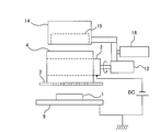
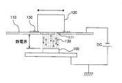
- FIG. 16 is a schematic view showing a conventional electrostatic screen printing apparatus.
- the electrostatic screen printing apparatus includes a stencil screen 110 disposed above the object (substrate) 100 and a rubbing brush 120 on the screen 110.
- Print patterns such as characters and figures are formed on the screen 110 by the mesh net 111.
- As the rubbing brush 120 a soft continuous foam urethane sponge is adopted because of the good rubbing property of the powder to the screen 110.
- the powder 130 is frictionally charged by rubbing the powder 130 onto the screen 110 by the rubbing brush 120, and the powder 130 is further pushed downward through the mesh net 111 of the screen 110.
- a high DC voltage is applied between the object 100 and the screen 110 by a DC power supply DC, and an electrostatic field is formed between the object 100 and the screen 110.
- the powder charged through the mesh network 111 adheres to the surface of the object 100 in a static electric field straight ahead toward the object 100 serving as a counter electrode. In this manner, a print pattern such as characters and graphics on the screen 110 is printed on the surface of the object 100.
- Such electrostatic screen printing techniques are used in a wide range of fields from confectionery to industrial products because uniform films made of powder can be formed on an object.
- the electrostatic screen printing apparatus is required to move the screen 110 away from the object 100 to some extent, as shown in FIG. This is because when the screen 110 is brought into contact with the object 100 or brought very close to the object 100, electricity flows between the screen 110 and the object 100 and no electrostatic field is formed between them. . However, when the object 100 and the screen 110 are separated, the outline of the print shape formed on the object 100 may be slightly blurred.
- one aspect of the present invention is an electrostatic printing apparatus for adhering powder to an object by electrostatic force, which is disposed between an electrode, the electrode and the object A screen, charging means for charging the powder on the screen, and a voltage application device for applying a voltage between the electrode and the object, the screen being formed of an insulating material It is characterized by
- a preferred embodiment of the present invention is characterized in that the screen is a mesh screen.
- a preferred embodiment of the present invention is characterized in that the mesh screen is formed of synthetic fibers.
- a preferred embodiment of the present invention is characterized in that the charging means is a rubbing member for rubbing the powder into the screen.
- a preferred embodiment of the present invention is characterized in that the electrode and the rubbing member are integrally formed.
- a preferred embodiment of the present invention is characterized in that the electrode and the rubbing member are formed of the same conductive material.
- a preferred aspect of the present invention is characterized in that the rubbing member is a rotatable cylindrical roller.
- a preferred embodiment of the present invention is characterized in that the electrode is disposed at the center of the roller.
- a preferred embodiment of the present invention further comprises a relative movement mechanism for relatively moving the roller and the screen in a state where the roller is in contact with the screen.
- a preferred embodiment of the present invention further comprises a hopper for feeding the powder onto the screen.
- a preferred embodiment of the present invention is characterized in that the charging means is a screen vibrating mechanism for vibrating the screen.
- an electrostatic printing apparatus for adhering powder to an object by electrostatic force, comprising: an electrode; a screen disposed between the electrode and the object; And a voltage application device for applying a voltage between the electrode and the object, wherein the screen is formed of an insulating material.
- a preferred embodiment of the present invention is characterized in that the screen is a mesh screen.
- a preferred embodiment of the present invention is characterized in that the mesh screen is formed of synthetic fibers.
- a preferred embodiment of the present invention further comprises a screen vibrating mechanism for vibrating the screen.
- Still another aspect of the present invention is an electrostatic printing method in which powder is attached to an object by electrostatic force, and a voltage is applied between the electrode and the object to form an electrostatic field, and the electrode The powder is frictionally charged on a screen made of an insulating material and disposed between the and the object to cause the powder to adhere to the object by electrostatic force.
- Still another aspect of the present invention is an electrostatic printing method in which powder is attached to an object by electrostatic force, and a voltage is applied between the electrode and the object to form an electrostatic field, and the electrode And charging the powder charged on a screen made of an insulating material, which is disposed between the and the object, and causing the powder to adhere to the object by electrostatic force.
- a preferred embodiment of the present invention is characterized in that the screen is a mesh screen.
- a preferred embodiment of the present invention is characterized in that the powder is a functional powder.
- a preferred embodiment of the present invention is characterized in that the object is an industrial product.
- the electrostatic printing technique according to the present invention is a technique for forming an electrostatic field between an electrode and an object without applying a voltage to a screen and adhering powder to the object using electrostatic force. According to the present invention, the following excellent effects can be obtained. (1) Since the screen is made of an insulating material, the screen can be placed in contact with or very close to the object. As a result, a clear pattern of the contour can be drawn on the object. (2) Since the screen can be brought into close proximity to the object, the thickness of the film made of powder deposited on the object can be controlled by the distance between the screen and the object. (3) As shown in FIG. 16, in the conventional electrostatic screen printing apparatus, an electrostatic field is formed between the lower surface of the screen 110 and the object 100.
- the charged powder 130 In order to apply an electrostatic force to the powder 130, the charged powder 130 needs to be rubbed in and pushed out into an electrostatic field by the brush 120. For this reason, an elastic body such as a sponge is used as the rubbing brush 120.
- the screen is placed in an electrostatic field, and the electrostatic field is formed not only below the screen but also above and inside (the holes through which the powder passes). There is no need to push the body down the screen.
- the powder passing through the screen may adhere to the lower surface of the screen without progressing toward the object.
- the powder is less likely to adhere to the lower surface of the screen than the conventional electrostatic screen printing apparatus.
- the screen is made of an insulating material and / or that electrostatic force acts on the powder even in the holes of the screen.
- materials other than metal, such as resin can be used as the material of the screen. Therefore, the electrostatic printing technology according to the present invention can meet such a demand.
- the screen is not metal
- powder which is not desirable to be in contact with metal for example, powder which easily reacts with metal
- the charge of the powder may change from negative to positive (or positive to negative) due to the influence of the charge of the object.
- the charge of the powder 130 in contact with the object 100 changes from negative to positive
- the powder 130 is attracted to the screen 110 and returns to the screen 110 against gravity.
- the strength of the electrostatic field is inversely proportional to the distance between the electrode and the object. Therefore, the electrostatic force acting on the powder can be weakened by increasing the distance between the electrode and the object.
- the distance between the electrode and the object it is possible to change the distance between the electrode and the object while maintaining the distance between the screen and the object, and vice versa. For example, it is possible to increase the distance between the electrode and the object while extremely shortening the distance between the screen and the object. Therefore, it is possible to prevent the above-described powder return while realizing clear printing. (7) Since the distance between the electrode and the object can be increased, discharge does not occur between the electrode and the object. Therefore, easily flammable powder can be used. In addition, electrostatic printing can be performed even in an easily flammable atmosphere. (8) The electrostatic printing technique according to the present invention can deposit powder on a target with a uniform thickness, as in the conventional electrostatic screen printing technique. Furthermore, it is also possible to form a multilayer film structure by repeatedly depositing different types of powders on the object.
- FIG. 1 is a schematic view showing an embodiment of an electrostatic printing apparatus according to the present invention. It is a figure which shows the example to which the electrode was earth
- FIG. It is a side view of the electrostatic printing apparatus shown in FIG. It is a schematic diagram which shows another modification of embodiment shown in FIG. It is a schematic diagram which shows the further another embodiment of this invention. It is a schematic diagram which shows the further another embodiment of this invention. It is a schematic diagram which shows the further another embodiment of this invention. It is a schematic diagram which shows the conventional electrostatic screen printing apparatus.
- the electrostatic printing apparatus according to the present invention is an electrostatic printing apparatus using an insulating screen, unlike the conventional electrostatic screen printing apparatus.
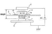
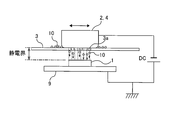
- FIG. 1 is a schematic view showing an embodiment of an electrostatic printing apparatus according to the present invention.
- the electrostatic printing apparatus includes an electrode 2 made of a conductive material such as metal, a screen 3 disposed between the electrode 2 and the object 1, and a rubbing member 4 for rubbing the powder 10 into the screen 3.
- a DC power source DC as a voltage application device for applying a DC voltage between the electrode 2 and the object 1.
- Examples of the object 1 include industrial products and confectionery.
- the screen 3 is horizontally supported by a support (not shown).
- the screen 3 is an insulating screen made of an insulating material.
- the screen 3 is made of a synthetic resin.
- the screen 3 is formed with a plurality of holes 3 a which allow the powder 10 to pass through.
- the plurality of holes 3a are arranged in accordance with a predetermined printing pattern. It is preferable to use a mesh screen as the screen 3. In this case, the print pattern is configured by a mesh.
- the mesh screen can be composed of synthetic fibers such as nylon or polyester.
- mesh screens made of nylon have the advantage of being less expensive or easier to manufacture than conventional stainless steel mesh screens.
- the rubbing member 4 is disposed on the screen 3.
- Various materials can be used for the rubbing member 4 such as elastic materials such as sponge and rubber, and hard materials such as wood and cured resin.
- the rubbing member 4 is a charging unit that generates frictional charge by rubbing the powder 10 into the screen 3 and charges the powder 10 on the screen 3.
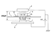
- the object 1 is placed on the stage 9, and the stage 9 is connected to the positive electrode of the DC power supply DC and grounded. As shown in FIG. 2, the electrode 2 may be grounded in consideration of workability and safety.
- the electrode 2 is disposed above the object 1 on the stage 9 and spaced apart from the object 1.
- the electrode 2 is connected to the negative electrode of the DC power supply DC.
- a DC voltage for example, 5000 V
- an electrostatic field is formed between the electrode 2 and the object 1.
- the screen 3 is located in this electrostatic field. Since the screen 3 is made of an insulating material, no voltage is applied to the screen 3 and the screen 3 is electrically isolated.
- the powder 10 is supplied to the upper surface of the screen 3. A voltage is applied between the electrode 2 and the object 1 to form an electrostatic field therebetween. While the powder 10 is present between the rubbing member 4 and the screen 3, the rubbing member 4 is rubbed against the screen 3. As a result, the powder 10 is negatively charged by frictional charging and is further rubbed into the screen 3. Since the triboelectric charging of the powder 10 takes place in an electrostatic field, an electrostatic force acts on the charged powder 10. Therefore, the powder 10 travels toward the object 1 through the holes 3 a formed in the screen 3. The powder 10 adheres to the object 1 in accordance with a printing pattern composed of a plurality of holes 3 a formed in the screen 3.
- the powder may be positively charged when it is rubbed into the screen 3 by the rubbing member 4.
- the electrode 2 is connected to the positive electrode of the DC power supply DC
- the stage 9 is connected to the negative electrode of the DC power supply DC.
- the rubbing member 4 may be in sliding contact with the screen 3 manually, or may be in sliding contact with the screen 3 by a drive mechanism. Alternatively, the position of the rubbing member 4 may be fixed, and the screen 3 may be moved relative to the rubbing member 4. Even in this case, the rubbing member 4 can rub the powder 10 into the screen 3.
- the screen 3 is placed in an electrostatic field, and the powder 10 is charged in the electrostatic field. Since the electrostatic field is formed not only below the screen 3 but also above and inside (the holes 3a through which the powder passes), there is no need to push the powder 10 below the screen 3. Therefore, it is not necessary to use an elastic body as the rubbing member 4.
- the material of the rubbing member 4 is not particularly limited as long as it is a material capable of causing frictional electrification of powder.
- the screen 3 can be brought into contact with or extremely close to the object 1.
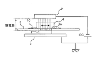
- the screen 3 it is also possible to place the screen 3 in contact with the object 1. According to such an arrangement, it is possible to print on the object 1 a clear pattern or a very thin linear pattern.
- FIG. 4 is an enlarged view schematically showing the screen 3 in contact with the object 1.
- the screen 3 is a mesh screen composed of a mesh net 7 and a pattern layer 8.
- the mesh net 7 is made of synthetic fibers such as nylon and polyester, and the pattern layer 8 is made of resin.
- the pattern layer 8 is formed on the lower surface of the mesh net 7.
- a printing pattern 8a is formed on the pattern layer 8, and the powder 10 rubbed into the screen 3 reaches the object 1 through the mesh net 7 and the printing pattern 8a, and a printing pattern along the printing pattern 8a Are formed on the object 1.
- the thickness of the printed pattern (for example, figures and characters) formed from the powder 10 on the object 1 is determined depending on the thickness of the pattern layer 8 Be done. For example, if the thickness of the print pattern formed on the object 1 is 80 ⁇ m, the screen 3 having the pattern layer 8 with a thickness of 80 ⁇ m is used. Thus, the thickness of the pattern can be controlled by the thickness of the pattern layer 8.
- an electrode moving mechanism 6 connected to the electrode 2 may be provided, and the electrode 2 may be moved parallel to the screen 3 by the electrode moving mechanism 6. According to such a configuration, printing can be performed on a larger object 1. Furthermore, the electrode 2 can be made smaller.
- the electrode moving mechanism 6 is constituted of, for example, a combination of a belt connected to the electrode 2 and a motor for driving the belt, or a combination of a ball screw and a servomotor.
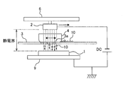
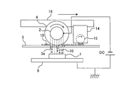
- FIG. 6 is a schematic view showing another embodiment of the present invention.
- the electrode 2 and the rubbing member 4 are integrally configured. More specifically, the electrode 2 is fixed to the upper surface of the rubbing member 4. When the powder 10 is scraped into the screen 3, the scraping member 4 moves integrally with the electrode 2.
- FIG. 7 is a schematic view showing still another embodiment of the present invention.
- the electrode 2 and the rubbing member 4 are made of the same conductive material, and the electrode 2 and the rubbing member 4 are provided as a single member.
- the electrode 2 and the rubbing member 4 are elements having different functions, the rubbing member 4 can also function as the electrode 2 by using a conductive material for the rubbing member 4.
- conductive resin, carbon or the like can be used.
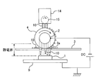
- FIG. 8 is a schematic view showing still another embodiment of the present invention.
- the configurations and operations which are not particularly described are the same as those of the above-described embodiment, and thus the description thereof will be omitted.
- a cylindrical roller is used as the rubbing member 4.
- the roller (sliding-in member) 4 is disposed such that its axial center is parallel to the screen 3, and the outer peripheral surface of the roller 4 is in contact with the upper surface of the screen 3.
- FIG. 9 is a side view of the electrostatic printing apparatus shown in FIG. As shown in FIG. 9, the roller 4 is connected to a motor 12, and the roller 4 is rotated about its axis by the motor 12, and the outer peripheral surface of the roller 4 is in sliding contact with the upper surface of the screen 3.
- the roller 4 is preferably formed of an elastic material such as urethane sponge or rubber.
- the electrode 2 is configured as a support shaft of the roller 4.
- the electrode 2 is disposed at the center of the roller 4, and the roller 4 is configured to rotate around the electrode 2.
- the electrode (support shaft) 2 is connected to a DC power supply DC. Therefore, an electrostatic field is formed between the electrode 2 and the object 1. As can be seen from FIG. 8, the lower part of the roller 4 located below the electrode 2 is placed in an electrostatic field.
- a hopper 14 for supplying the powder 10 to the outer peripheral surface of the roller 4 is disposed above the roller 4, a hopper 14 for supplying the powder 10 to the outer peripheral surface of the roller 4 is disposed.
- the powder 10 is stored inside the hopper 14.
- a plurality of holes (not shown) for allowing the passage of powder are formed, and a rotating brush 15 is disposed to cover these holes.
- the supply amount of the powder 10 can be controlled by the rotational speed of the rotating brush 15.
- the powder 10 is conveyed to the upper surface of the screen 3 by the rotation of the roller 4. Then, the powder 10 is rubbed into the screen 3 by the rotating roller 4 and charged by friction.
- the charged powder 10 travels toward the object 1 by electrostatic force and adheres to the object 1.
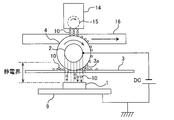
- FIG. 10 is a schematic view showing a modification of the embodiment shown in FIG. 8, and FIG. 11 is a side view of the electrostatic printing apparatus shown in FIG.
- a relative movement mechanism 16 for moving the roller 4 relative to the screen 3 is provided.
- the relative movement mechanism 16 moves the roller 4 parallel to the screen 3 in the direction indicated by the arrow while the roller 4 is in contact with the upper surface of the screen 3.
- the moving direction of the roller 4 is a direction perpendicular to the axial center of the roller 4.
- the hopper 14 is also connected to the relative movement mechanism 16, and the roller 4 and the hopper 14 are integrally moved by the relative movement mechanism 16.
- the roller 4 rubs the powder 10 onto the screen 3 while moving on the screen 3.
- the powder 10 can be attached to a larger area on the object 1.
- the relative movement mechanism 16 is constituted of, for example, a combination of a belt connected to the motor 12 and the hopper 14 and a motor for driving the belt, or a combination of a ball screw and a servomotor.
- the relative movement mechanism 16 shown in FIGS. 10 and 11 moves the roller 4 and the hopper 14, as another example, the relative movement mechanism 16 moves the screen 3 horizontally relative to the roller 4 and the hopper 14. You may Even in this case, the roller (sliding member) 4 and the screen 3 can move relative to each other while maintaining the contact state, and the roller 4 can rub the powder 10 into the screen 3.
- FIG. 12 is a schematic view showing another modified example of the embodiment shown in FIG.
- the configuration of this example is basically the same as the configuration shown in FIG. 10, but differs from the above-described example in that the hopper 14 is disposed side by side with the roller 4. More specifically, the hopper 14 is disposed forward with respect to the traveling direction of the roller 4 indicated by the arrow. The hopper 14 supplies the powder 10 directly to the upper surface of the screen 3, and the roller 4 rubs the powder 10 on the screen 3 into the screen 3.
- the hopper 14 is moved by the relative moving mechanism 16 in synchronization with the roller 4, but a hopper moving mechanism may be provided to move the hopper 14 independently of the roller 4.
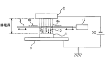
- FIG. 13 is a schematic view showing still another embodiment of the present invention.
- a screen vibrating mechanism 17 is provided instead of the rubbing member 4 as charging means for charging the powder 10 on the screen 3.
- the screen vibrating mechanism 17 causes the powder 10 on the screen 3 to be frictionally charged by vibrating the screen 3 in the horizontal direction.
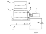
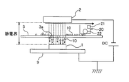
- FIG. 14 is a schematic view showing still another embodiment of the present invention.
- a powder distribution mechanism 20 is provided above the screen 3 in place of the rubbing member 4.
- the powder spraying mechanism 20 stores powder inside.
- the powder distribution mechanism 20 has a charging device 21 such as a corona discharge device, and can charge the powder stored inside.
- a plurality of holes (not shown) which allow the passage of the powder are formed, and the rotating brush 22 is disposed so as to cover the holes. By rotating the rotating brush 22, the powder stored inside the powder distribution mechanism 20 is supplied onto the screen 3 through the holes.
- the powder distribution mechanism 20 is movable in parallel with the screen 3.
- the powder distribution mechanism 20 supplies charged powder 10 onto the screen 3 while moving in parallel with the screen 3.
- the powder 10 on the screen 3 travels toward the object 1 through the holes 3 a of the screen 3 by the action of electrostatic force and adheres to the object 1.
- the powder may be supplied onto the screen 3 by the powder distribution mechanism 20, or the powder may be screen 3 by the powder distribution mechanism 20.
- a voltage may be applied between the electrode 2 and the object 1.
- the screen vibration mechanism 17 described above may be incorporated into the present embodiment.
- the electrode 2 may be moved parallel to the screen 3 while applying a voltage between the electrode 2 and the object 1.
- FIG. 15 is a schematic view showing still another embodiment of the present invention.
- the electrode 2 is covered by the insulating member 25.
- An example of the insulating member 25 is an insulating film having a thickness of about 1 mm.
- the insulating member 25 covers a horizontal surface (bottom surface) facing the screen 3 of the electrode 2 and a side surface connected to the horizontal surface.
- the screen 3 is made of an insulating material, the screen 3 can be placed in contact with or very close to the object 1. As a result, a clear pattern of the contour can be drawn on the object 1.
- the screen 3 can be brought extremely close to the object 1, the thickness of the film made of the powder deposited on the object 1 can be controlled by the distance between the screen 3 and the object 1 Can.
- an electrostatic field is formed between the lower surface of the screen 110 and the object 100. In order to apply electrostatic force to the powder 130, it is necessary to slide the charged powder 130 into the static electric field by the brush 120.
- the screen 3 is placed in an electrostatic field, and the electrostatic field is formed not only below the screen 3 but also above and inside (the holes 3a through which the powder passes). Therefore, there is no need to push the powder below the screen 3.
- the powder passing through the screen may adhere to the lower surface of the screen without progressing toward the object. According to the present invention, it has been experimentally confirmed that the powder is less likely to adhere to the lower surface of the screen 3 than the conventional electrostatic screen printing apparatus.
- the screen 3 is made of an insulating material and / or that electrostatic force acts on the powder among the holes of the screen.
- materials other than metal such as resin, can be used as the material of the screen 3. Therefore, the electrostatic printing technology according to the present invention can meet such a demand.
- the screen 3 is not a metal, it is possible to use a powder which is not preferable to be in contact with the metal (for example, a powder which easily reacts with the metal).
- the charge of the powder may change from negative to positive (or positive to negative) due to the influence of the charge of the object.
- the charge of the powder 130 in contact with the object 100 changes from negative to positive
- the powder 130 is attracted to the screen 110 and returns to the screen 110 against gravity.
- the strength of the electrostatic field is inversely proportional to the distance between the electrode and the object. Therefore, the electrostatic force acting on the powder can be weakened by increasing the distance between the electrode and the object.
- the distance between the electrode 2 and the object 1 can be changed while maintaining the distance between the screen 3 and the object 1, and vice versa.
- the distance between the electrode 2 and the object 1 can be increased while the distance between the screen 3 and the object 1 is extremely shortened. Therefore, it is possible to prevent the above-described powder return while realizing clear printing. (7) Since the distance between the electrode 2 and the object 1 can be increased, the discharge between the electrode 2 and the object 1 does not occur. Therefore, easily flammable powder can be used. In addition, electrostatic printing can be performed even in an easily flammable atmosphere. (8) The electrostatic printing technique according to the present invention can deposit the powder on the object 1 with a uniform thickness, as in the conventional electrostatic screen printing technique. Furthermore, it is also possible to form a multilayer film structure by depositing different types of powder repeatedly on the object 1.
- powders examples include edible powders and functional powders.
- Functional powder includes electrode powder, insulating powder, conductive powder constituting wiring and conductive film, carbon powder, metal powder, resin powder, pigment, powder coating, powder rubber, semiconductor It includes powders, powdery chemicals, and any functional powder to which electrostatic force acts.
- the present invention is applicable to all products in which functional powders are used, and examples thereof include primary batteries, secondary batteries, chemical cells such as fuel cells, physical cells such as solar cells, liquid crystal displays, Display devices such as plasma displays and organic EL displays, parts of power machinery such as internal combustion engines, cosmetics, daily goods, articles with pictures, household goods, clothes, footwear, semiconductor devices, electric elements such as capacitors and diodes, Parts of manufacturing equipment and processing machines, parts of vehicles (cars, bicycles, motorcycles, railways, aircrafts, ships, etc.), medical equipment, cookware, stationery, building components, glass products, furniture, sports equipment, textiles, rugs, The equipment for play etc. are mentioned.
- the present invention is applicable to an electrostatic printing apparatus and an electrostatic printing method using a screen made of an insulating material.
- Target object printed material
- Reference Signs List 2 electrode 3 screen 4 rubbing member 6 electrode moving mechanism 7 mesh network 8 pattern layer 9 stage 10 powder 12 motor 14 hopper 15 rotating brush 16 relative moving mechanism 17 screen vibrating mechanism 20 powder scattering mechanism 21 charging device 22 rotating brush 25 insulation Element
Landscapes
- Physics & Mathematics (AREA)
- General Physics & Mathematics (AREA)
- Screen Printers (AREA)
- Printing Methods (AREA)
Abstract
本発明は、従来の静電スクリーン印刷技術に代わる新規な静電印刷技術を提供する。静電印刷装置は、静電力により粉体を対象物に付着させる装置である。この静電印刷装置は、対象物1の上方に配置された電極2と、電極2と対象物1との間に配置されたスクリーン3と、スクリーン3上の粉体10を帯電させる擦り込み部材4と、電極2と対象物1との間に電圧を印加してこれらの間に静電界を形成する電圧印加装置DCとを備え、スクリーン3は絶縁材から形成されている。
Description
本発明は、機能性粉体や可食性粉体などの粉体を静電力により対象物に付着させる静電印刷装置および静電印刷方法に関し、特に絶縁材からなるスクリーンを用いた静電印刷装置および静電印刷方法に関する。
粉体を静電力により対象物に付着させる装置として、静電スクリーン印刷装置が知られている。図16は、従来の静電スクリーン印刷装置を示す模式図である。図16に示すように、静電スクリーン印刷装置は、対象物(被印刷物)100の上方に配置されるステンシルスクリーン110と、スクリーン110上の擦り込みブラシ120とを備えている。スクリーン110には文字や図形などの印刷パターンがメッシュ網111によって形成されている。擦り込みブラシ120としては、スクリーン110に対する粉体の擦込性の良さから軟質の連泡ウレタンスポンジが採用されている。
擦り込みブラシ120により粉体130をスクリーン110に擦り込むことによって粉体130は摩擦帯電し、さらにスクリーン110のメッシュ網111を通って下方に押し出される。対象物100とスクリーン110との間には直流電源DCによって直流高電圧が印加され、対象物100とスクリーン110との間に静電界が形成されている。メッシュ網111を通過し荷電された粉体は、静電界中を対電極である対象物100に向かって直進して対象物100の表面に付着する。このようにして、スクリーン110の文字や図形などの印刷パターンが対象物100の表面に印刷される。このような静電スクリーン印刷技術は、粉体からなる均一な膜を対象物上に形成することができるので、菓子から工業製品に至るまで幅広い分野で使用されている。
静電スクリーン印刷装置は、図16に示すように、スクリーン110を対象物100からある程度離すことが必要とされる。これは、スクリーン110を対象物100に接触させる、または対象物100に極めて近づけると、スクリーン110と対象物100との間に電気が流れてしまい、これらの間に静電界が形成されないからである。しかしながら、対象物100とスクリーン110との間を離間させると、対象物100上に形成された印刷形状の輪郭が僅かにぼやけてしまうことがあった。
本発明は、従来の静電スクリーン印刷技術に代わる新規な静電印刷技術を提供することを目的とする。
上述した目的を達成するために、本発明の一態様は、静電力により粉体を対象物に付着させる静電印刷装置であって、電極と、前記電極と前記対象物との間に配置されたスクリーンと、前記スクリーン上の前記粉体を帯電させる帯電手段と、前記電極と前記対象物との間に電圧を印加する電圧印加装置とを備え、前記スクリーンは絶縁材から形成されていることを特徴とする。
本発明の好ましい態様は、前記スクリーンはメッシュスクリーンであることを特徴とする。
本発明の好ましい態様は、前記メッシュスクリーンは、合成繊維から形成されていることを特徴とする。
本発明の好ましい態様は、前記メッシュスクリーンは、合成繊維から形成されていることを特徴とする。
本発明の好ましい態様は、前記帯電手段は、前記粉体を前記スクリーンに擦り込む擦り込み部材であることを特徴とする。
本発明の好ましい態様は、前記電極と前記擦り込み部材は、一体に構成されていることを特徴とする。
本発明の好ましい態様は、前記電極と前記擦り込み部材は、同じ導電性材料から形成されていることを特徴とする。
本発明の好ましい態様は、前記電極と前記擦り込み部材は、一体に構成されていることを特徴とする。
本発明の好ましい態様は、前記電極と前記擦り込み部材は、同じ導電性材料から形成されていることを特徴とする。
本発明の好ましい態様は、前記擦り込み部材は、回転可能な円筒状のローラであることを特徴とする。
本発明の好ましい態様は、前記電極は、前記ローラの中心に配置されていることを特徴とする。
本発明の好ましい態様は、前記ローラを前記スクリーンに接触させた状態で、前記ローラと前記スクリーンとを相対的に移動させる相対移動機構をさらに備えたことを特徴とする。
本発明の好ましい態様は、前記電極は、前記ローラの中心に配置されていることを特徴とする。
本発明の好ましい態様は、前記ローラを前記スクリーンに接触させた状態で、前記ローラと前記スクリーンとを相対的に移動させる相対移動機構をさらに備えたことを特徴とする。
本発明の好ましい態様は、前記スクリーン上に前記粉体を供給するホッパをさらに備えたことを特徴とする。
本発明の好ましい態様は、前記帯電手段は、前記スクリーンを振動させるスクリーン振動機構であることを特徴とする。
本発明の好ましい態様は、前記帯電手段は、前記スクリーンを振動させるスクリーン振動機構であることを特徴とする。
本発明の他の態様は、静電力により粉体を対象物に付着させる静電印刷装置であって、電極と、前記電極と前記対象物との間に配置されたスクリーンと、帯電した粉体を前記スクリーン上に散布する粉体散布機構と、前記電極と前記対象物との間に電圧を印加する電圧印加装置とを備え、前記スクリーンは絶縁材から形成されていることを特徴とする。
本発明の好ましい態様は、前記スクリーンはメッシュスクリーンであることを特徴とする。
本発明の好ましい態様は、前記メッシュスクリーンは、合成繊維から形成されていることを特徴とする。
本発明の好ましい態様は、前記スクリーンを振動させるスクリーン振動機構をさらに備えたことを特徴とする。
本発明の好ましい態様は、前記メッシュスクリーンは、合成繊維から形成されていることを特徴とする。
本発明の好ましい態様は、前記スクリーンを振動させるスクリーン振動機構をさらに備えたことを特徴とする。
本発明のさらに他の態様は、静電力により粉体を対象物に付着させる静電印刷方法であって、電極と前記対象物との間に電圧を印加して静電界を形成し、前記電極と前記対象物との間に配置された、絶縁材からなるスクリーン上で前記粉体の摩擦帯電を起こして、前記粉体を静電力により前記対象物に付着させることを特徴とする。
本発明のさらに他の態様は、静電力により粉体を対象物に付着させる静電印刷方法であって、電極と前記対象物との間に電圧を印加して静電界を形成し、前記電極と前記対象物との間に配置された、絶縁材からなるスクリーン上に荷電した粉体を散布し、前記粉体を静電力により前記対象物に付着させることを特徴とする。
本発明の好ましい態様は、前記スクリーンはメッシュスクリーンであることを特徴とする。
本発明の好ましい態様は、前記粉体は、機能性粉体であることを特徴とする。
本発明の好ましい態様は、前記対象物は、工業製品であることを特徴とする。
本発明のさらに他の態様は、静電力により粉体を対象物に付着させる静電印刷方法であって、電極と前記対象物との間に電圧を印加して静電界を形成し、前記電極と前記対象物との間に配置された、絶縁材からなるスクリーン上に荷電した粉体を散布し、前記粉体を静電力により前記対象物に付着させることを特徴とする。
本発明の好ましい態様は、前記スクリーンはメッシュスクリーンであることを特徴とする。
本発明の好ましい態様は、前記粉体は、機能性粉体であることを特徴とする。
本発明の好ましい態様は、前記対象物は、工業製品であることを特徴とする。
本発明に係る静電印刷技術は、スクリーンに電圧を印加せずに電極と対象物との間に静電界を形成し、静電力を利用して粉体を対象物に付着させる技術である。
本発明によれば、次に列挙する優れた効果を得ることができる。
(1)スクリーンは絶縁材から構成されているので、スクリーンを対象物に接触させる、または極めて近づけて配置することができる。その結果として、輪郭の鮮明な模様を対象物上に描くことができる。
(2)スクリーンを対象物に極めて近接させることができるので、スクリーンと対象物との間の距離により、対象物上に堆積した粉体からなる膜の厚さを制御することができる。
(3)図16に示すように、従来の静電スクリーン印刷装置では、スクリーン110の下面と対象物100との間に静電界が形成される。粉体130に静電力を作用させるためには、荷電した粉体130を擦り込みブラシ120によって静電界中に押し出す必要がある。このような理由から、スポンジなどの弾性体が擦り込みブラシ120に使用されている。これに対し、本発明によれば、スクリーンは静電界中に置かれ、静電界はスクリーンの下方のみならず、上方、および内部(粉体が通過する孔)にも形成されているので、粉体をスクリーンの下方に押し出す必要がない。
(4)特許文献1に記載されているように、従来の静電スクリーン印刷装置では、スクリーンを通過した粉体が対象物に向かって進まずに、スクリーンの下面に付着することがある。本発明によれば、従来の静電スクリーン印刷装置よりも、スクリーンの下面に粉体が付着しにくいことが実験により確かめられている。粉体が付着しにくい理由はよく分かっていないが、スクリーンが絶縁材から構成されていること、および/またはスクリーンの孔の中でも静電力が粉体に作用することが考えられる。
(5)対象物の種類によっては、粉体への金属の混入が厳しく禁止されているものがある。本発明によれば、スクリーンの材料として、金属以外の材料、例えば樹脂などを使用することができる。したがって、本発明に係る静電印刷技術は、そのような要請に応えることができる。さらに、スクリーンが金属でないため、金属と接触させることが好ましくない粉体(例えば、金属と反応しやすい粉体)も使用することができる。
(6)粉体が対象物に付着すると、対象物の電荷の影響により粉体の電荷が負から正(または正から負)に変わることがある。例えば、図16において、対象物100に接触した粉体130の電荷が負から正に変わると、粉体130はスクリーン110に引き寄せられ、重力に逆らってスクリーン110に戻ってしまう。このような粉体の動きは、静電力が強いほど起こりやすい。静電界の強さは、電極と対象物との距離に反比例する。したがって、粉体に作用する静電力は、電極と対象物との距離を大きくすることによって弱めることができる。本発明によれば、スクリーンと対象物との間の距離を維持しつつ、電極と対象物との距離を変えることができ、その逆も可能である。例えば、スクリーンと対象物との距離を極めて短くする一方で、電極と対象物との距離を長くすることが可能である。したがって、鮮明な印刷を実現しつつ、上述した粉体の戻りを防止することができる。
(7)電極と対象物との距離を長くすることができるので、電極と対象物との間での放電が発生しない。したがって、発火しやすい粉体を使用することができる。また、発火しやすい雰囲気でも静電印刷を行うことができる。
(8)本発明に係る静電印刷技術は、従来の静電スクリーン印刷技術と同様に、粉体を均一な厚さで対象物上に堆積させることができる。さらに、異なる種類の粉体を繰り返し対象物上に堆積させることにより、多層膜構造を形成することも可能である。
以下、本発明の実施形態について図面を参照して説明する。同一の要素には同一の符号を付して、その重複する説明を省略する。
本発明に係る静電印刷装置は、従来の静電スクリーン印刷装置とは異なり、絶縁スクリーンを用いた静電印刷装置である。図1は、本発明に係る静電印刷装置の一実施形態を示す模式図である。静電印刷装置は、金属などの導電性材料から構成された電極2と、この電極2と対象物1との間に配置されたスクリーン3と、粉体10をスクリーン3に擦り込む擦り込み部材4と、電極2と対象物1との間に直流電圧を印加する電圧印加装置としての直流電源DCとを備えている。対象物1の例としては、工業製品や菓子などが挙げられる。
本発明に係る静電印刷装置は、従来の静電スクリーン印刷装置とは異なり、絶縁スクリーンを用いた静電印刷装置である。図1は、本発明に係る静電印刷装置の一実施形態を示す模式図である。静電印刷装置は、金属などの導電性材料から構成された電極2と、この電極2と対象物1との間に配置されたスクリーン3と、粉体10をスクリーン3に擦り込む擦り込み部材4と、電極2と対象物1との間に直流電圧を印加する電圧印加装置としての直流電源DCとを備えている。対象物1の例としては、工業製品や菓子などが挙げられる。
スクリーン3は、支持材(図示せず)により水平に支持されている。スクリーン3は、絶縁材から構成された絶縁スクリーンである。例えば、スクリーン3は合成樹脂から構成される。スクリーン3には、粉体10の通過を許容する複数の孔3aが形成されている。これら複数の孔3aは予め定められた印刷パターンに従って配列されている。スクリーン3としては、メッシュスクリーンを用いるのが好ましい。この場合、印刷パターンはメッシュによって構成される。メッシュスクリーンは、ナイロンやポリエステルなどの合成繊維から構成することができる。特に、ナイロンから構成されたメッシュスクリーンは、従来のステンレスメッシュスクリーンに比べて価格が安く、または製造が簡単であるという利点がある。
擦り込み部材4は、スクリーン3の上に配置される。擦り込み部材4には、スポンジやゴム等の弾性材、木材や硬化樹脂等の硬質材など、さまざまな材料が使用できる。この擦り込み部材4は、粉体10をスクリーン3に擦り込むことによって摩擦帯電を起こし、スクリーン3上の粉体10を帯電させる帯電手段である。
対象物1はステージ9の上に置かれており、ステージ9は直流電源DCの正極に接続されるとともに接地されている。なお、図2に示すように、作業性および安全性などを考慮して、電極2を接地してもよい。電極2は、ステージ9上の対象物1の上方に配置され、対象物1から離間して配置される。電極2は直流電源DCの負極に接続されている。直流電源DCにより電極2と対象物1との間に直流電圧(例えば、5000V)が印加されると、電極2と対象物1との間には静電界が形成される。スクリーン3は、この静電界の中に位置している。このスクリーン3は絶縁材から構成されているので、スクリーン3には電圧は印加されず、スクリーン3は電気的に絶縁されている。
次に、図1に示す静電印刷装置を用いた印刷方法について説明する。粉体10は、スクリーン3の上面に供給される。電極2と対象物1との間に電圧を印加してこれらの間に静電界を形成する。擦り込み部材4とスクリーン3との間に粉体10が存在した状態で、擦り込み部材4をスクリーン3に擦り付ける。その結果、粉体10は摩擦帯電により負に荷電され、さらにスクリーン3に擦り込まれる。粉体10の摩擦帯電は静電界中で起きるので、荷電された粉体10には静電力が作用する。したがって、粉体10はスクリーン3に形成されている孔3aを通って対象物1に向かって進行する。粉体10は、スクリーン3に形成された複数の孔3aから構成される印刷パターンに従って対象物1に付着する。
なお、粉体の種類によっては、擦り込み部材4でスクリーン3に擦り込まれるときに粉体が正に帯電することがある。このような粉体を使用するときは、電極2は直流電源DCの正極に接続され、ステージ9は直流電源DCの負極に接続される。
擦り込み部材4は、手動でスクリーン3に摺接させてもよく、または駆動機構によりスクリーン3に摺接させてもよい。あるいは、擦り込み部材4の位置を固定し、スクリーン3を擦り込み部材4に対して移動させてもよい。この場合でも、擦り込み部材4は粉体10をスクリーン3に擦り込むことが可能である。
スクリーン3は静電界中に置かれ、静電界中で粉体10が帯電される。静電界はスクリーン3の下方のみならず、上方、および内部(粉体が通過する孔3a)にも形成されているので、粉体10をスクリーン3の下方に押し出す必要がない。したがって、擦り込み部材4として弾性体を使用する必要がない。粉体の摩擦帯電を起こすことが可能な材料であれば、擦り込み部材4の材料は特に限定されない。
本発明によれば、絶縁材からなるスクリーン3には電圧が印加されない。したがって、スクリーン3を対象物1に接触させる、または極めて近づけることが可能となる。例えば、図3に示すように、スクリーン3を対象物1に接触して配置することも可能である。このような配置によれば、輪郭のはっきりした模様や、極めて細い線状の模様を対象物1に印刷することができる。
さらに、スクリーン3を対象物1に接触させることにより、対象物1上の印刷模様(例えば、図形や文字)の厚さを、スクリーン3自体の厚さによって制御することができる。図4は、対象物1に接触しているスクリーン3を模式的に示す拡大図である。図4に示すように、スクリーン3は、メッシュ網7とパターン層8から構成されたメッシュスクリーンである。メッシュ網7は、ナイロンやポリエステルなどの合成繊維から構成され、パターン層8は樹脂から構成されている。パターン層8は、メッシュ網7の下面に形成されている。パターン層8には印刷パターン8aが形成されており、スクリーン3に擦り込まれた粉体10は、メッシュ網7および印刷パターン8aを通って対象物1に到達し、印刷パターン8aに沿った印刷模様を対象物1上に形成する。
スクリーン3は対象物1に接触しているので、対象物1上の粉体10から形成される印刷模様(例えば、図形や文字)の厚さは、パターン層8の厚さに依存して決定される。例えば、対象物1に形成される印刷模様の厚さが80μmである場合は、厚さ80μmのパターン層8を有したスクリーン3が使用される。このように、パターン層8の厚さによって印刷模様の厚さをコントロールすることができる。
図5に示すように、電極2に連結された電極移動機構6を設け、この電極移動機構6により電極2をスクリーン3と平行に移動させてもよい。このような構成によれば、より大きな対象物1に印刷することができる。さらに、電極2を小さくすることもできる。電極移動機構6は、例えば、電極2に連結されたベルトと、このベルトを駆動するモータとの組み合わせ、またはボールねじとサーボモータとの組み合わせなどから構成される。
図6は、本発明の他の実施形態を示す模式図である。この実施形態では、電極2と擦り込み部材4とは一体に構成されている。より具体的には、電極2は擦り込み部材4の上面に固定されている。粉体10をスクリーン3に擦り込むときは、擦り込み部材4は電極2と一体に移動する。
図7は、本発明のさらに他の実施形態を示す模式図である。この実施形態では、電極2と擦り込み部材4とは同一の導電性材料から構成されており、電極2と擦り込み部材4は単一の部材として設けられている。電極2と擦り込み部材4は機能としては異なる要素であるが、擦り込み部材4に導電性材料を使用することにより、擦り込み部材4は電極2としても機能することが可能である。例えば、導電性樹脂、カーボンなどを使用することができる。
図8は、本発明のさらに他の実施形態を示す模式図である。特に説明しない構成および動作は、上述の実施形態と同様であるので、その重複する説明を省略する。この実施形態では、擦り込み部材4として、円筒状のローラが使用されている。このローラ(擦り込み部材)4はその軸心がスクリーン3と平行になるように配置され、ローラ4の外周面がスクリーン3の上面に接触している。図9は、図8に示す静電印刷装置の側面図である。図9に示すように、ローラ4はモータ12に連結されており、このモータ12によってローラ4はその軸心を中心として回転し、ローラ4の外周面がスクリーン3の上面と摺接する。ローラ4とスクリーン3との接触面積を大きくするために、ローラ4はウレタンスポンジやゴムなどの弾性材から形成されることが好ましい。
電極2は、ローラ4の支持軸として構成されている。電極2はローラ4の中心に配置されており、ローラ4はこの電極2を中心に回転するようになっている。電極(支持軸)2は、直流電源DCに接続されている。したがって、電極2と対象物1との間には静電界が形成される。図8から分かるように、電極2よりも下に位置するローラ4の下部は、静電界中に置かれている。
ローラ4の上方には、ローラ4の外周面に粉体10を供給するホッパ14が配置されている。このホッパ14の内部には粉体10が貯留されている。ホッパ14の底には粉体の通過を許容する複数の孔(図示せず)が形成されており、これらの孔を覆うように回転ブラシ15が配置されている。この回転ブラシ15が回転することにより、粉体10がホッパ14の底部の孔を通じてローラ4に供給されるようになっている。粉体10の供給量は、回転ブラシ15の回転速度によって制御することができる。粉体10はローラ4の回転によりスクリーン3の上面に運ばれる。そして、回転するローラ4により粉体10はスクリーン3に擦り込まれ、摩擦により荷電する。荷電した粉体10は、静電力によって対象物1に向かって進行し、対象物1に付着する。
図10は、図8に示す実施形態の変形例を示す模式図であり、図11は図10に示す静電印刷装置の側面図である。この例では、ローラ4をスクリーン3に対して移動させる相対移動機構16が設けられている。この相対移動機構16は、ローラ4がスクリーン3の上面に接触した状態で、このローラ4をスクリーン3と平行に矢印で示す方向に移動させる。ローラ4の移動方向は、ローラ4の軸心と垂直な方向である。ホッパ14もこの相対移動機構16に連結されており、ローラ4とホッパ14は相対移動機構16により一体に移動するようになっている。ローラ4は、スクリーン3上を移動しながら、粉体10をスクリーン3に擦り込む。この例によれば、対象物1上のより大きな領域に粉体10を付着させることが可能である。相対移動機構16は、例えば、モータ12およびホッパ14に連結されたベルトと、このベルトを駆動するモータとの組み合わせ、またはボールねじとサーボモータとの組み合わせなどから構成される。
図10および図11に示す相対移動機構16はローラ4およびホッパ14を移動させるが、別の例として、相対移動機構16は、スクリーン3をローラ4およびホッパ14に対して相対的に水平に移動させてもよい。この場合でも、ローラ(擦り込み部材)4とスクリーン3は接触した状態を保ちながら、相対的に移動することが可能であり、ローラ4は粉体10をスクリーン3に擦り込むことができる。
図12は、図8に示す実施形態の別の変形例を示す模式図である。この例の構成は、基本的には図10に示す構成と同じであるが、ホッパ14がローラ4と並んで配置されている点で上述の例とは異なっている。より具体的には、ホッパ14は、矢印で示すローラ4の進行方向に対して前方に配置されている。ホッパ14は粉体10を直接スクリーン3の上面に供給し、スクリーン3上の粉体10をローラ4がスクリーン3に擦り込む。
ホッパ14はローラ4と同期して相対移動機構16により移動されるが、ローラ4とは独立してホッパ14を移動させるホッパ移動機構を設けてもよい。
図13は、本発明のさらに他の実施形態を示す模式図である。図13に示すように、本実施形態では、スクリーン3上の粉体10を帯電させる帯電手段として、擦り込み部材4に代えて、スクリーン振動機構17が設けられている。このスクリーン振動機構17は、スクリーン3を水平方向に振動させることによって、スクリーン3上の粉体10に摩擦帯電を起こさせるものである。
静電界は、スクリーン3を通過して形成されている。したがって、荷電したスクリーン3上の粉体10に静電力が作用し、粉体10はスクリーン3の孔3aを通過して対象物1に向かって進行する。このように、粉体10をスクリーン3の下方に押し出す必要がないので、擦り込み部材4を省略してもよい。図5に示すように、電極2をスクリーン3と平行に移動させてもよい。また、擦り込み部材4とスクリーン振動機構17とを併設してもよい。
図14は、本発明のさらに他の実施形態を示す模式図である。この実施形態では、擦り込み部材4に代えて、粉体散布機構20がスクリーン3の上方に設けられている。この粉体散布機構20はその内部に粉体を貯留している。粉体散布機構20は、コロナ放電装置などの帯電装置21を有しており、内部に貯留している粉体を帯電させることが可能となっている。粉体散布機構20の底部には粉体の通過を許容する複数の孔(図示せず)が形成されており、この孔を覆うように回転ブラシ22が配置されている。この回転ブラシ22を回転させることによって、粉体散布機構20の内部に貯留されている粉体が孔を通ってスクリーン3上に供給されるようになっている。図14の矢印で示すように、粉体散布機構20は、スクリーン3と平行に移動可能となっている。
粉体散布機構20は、スクリーン3と平行に移動しながら、荷電した粉体10をスクリーン3上に供給する。スクリーン3上の粉体10は、静電力の作用によってスクリーン3の孔3aを通って対象物1に向かって進行し、対象物1に付着する。電極2と対象物1との間に電圧を印加している状態で、粉体散布機構20により粉体をスクリーン3上に供給してもよく、または粉体散布機構20により粉体をスクリーン3上に供給した後に、電極2と対象物1との間に電圧を印加してもよい。上述したスクリーン振動機構17を本実施形態に組み込んでもよい。さらに、図5に示すように、電極2と対象物1との間に電圧を印加しながら、電極2をスクリーン3と平行に移動させてもよい。
図15は、本発明のさらに他の実施形態を示す模式図である。この実施形態では、電極2は絶縁部材25によって覆われている。この絶縁部材25の一例は、厚さ1mm程度の絶縁膜である。絶縁部材25は、電極2のスクリーン3に対向する水平面(底面)と、この水平面に接続される側面を覆っている。電極2を絶縁部材25で覆うことにより、電極2と対象物1との距離を短くしても、これらの間に放電が起こりにくくなる。したがって、爆発や火災などの事故を防止することができる。また、発火しやすい粉体を使用することができ、また発火しやすい雰囲気でも静電印刷を行うことができる。
本発明によれば、次に列挙する優れた効果を得ることができる。
(1)スクリーン3は絶縁材から構成されているので、スクリーン3を対象物1に接触させる、または極めて近づけて配置することができる。その結果として、輪郭の鮮明な模様を対象物1上に描くことができる。
(2)スクリーン3を対象物1に極めて近接させることができるので、スクリーン3と対象物1との間の距離により、対象物1上に堆積した粉体からなる膜の厚さを制御することができる。
(3)図16に示すように、従来の静電スクリーン印刷装置では、スクリーン110の下面と対象物100との間に静電界が形成される。粉体130に静電力を作用させるためには、荷電した粉体130を摺り込みブラシ120によって静電界中に押し出す必要がある。このような理由から、スポンジなどの弾性体が擦り込みブラシ120に使用されている。これに対し、本発明によれば、スクリーン3は静電界中に置かれ、静電界はスクリーン3の下方のみならず、上方、および内部(粉体が通過する孔3a)にも形成されているので、粉体をスクリーン3の下方に押し出す必要がない。
(4)特許文献1に記載されているように、従来の静電スクリーン印刷装置では、スクリーンを通過した粉体が対象物に向かって進まずに、スクリーンの下面に付着することがある。本発明によれば、従来の静電スクリーン印刷装置よりも、スクリーン3の下面に粉体が付着しにくいことが実験により確かめられている。粉体が付着しにくい理由はよく分かっていないが、スクリーン3が絶縁材から構成されていること、および/またはスクリーンの孔の中でも静電力が粉体に作用することが考えられる。
(5)対象物の種類によっては、粉体への金属の混入が厳しく禁止されているものがある。本発明によれば、スクリーン3の材料として、金属以外の材料、例えば樹脂などを使用することができる。したがって、本発明に係る静電印刷技術は、そのような要請に応えることができる。さらに、スクリーン3が金属でないため、金属と接触させることが好ましくない粉体(例えば、金属と反応しやすい粉体)も使用することができる。
(6)粉体が対象物に付着すると、対象物の電荷の影響により粉体の電荷が負から正(または正から負)に変わることがある。例えば、図16において、対象物100に接触した粉体130の電荷が負から正に変わると、粉体130はスクリーン110に引き寄せられ、重力に逆らってスクリーン110に戻ってしまう。このような粉体130の動きは、静電力が強いほど起こりやすい。静電界の強さは、電極と対象物との距離に反比例する。したがって、粉体に作用する静電力は、電極と対象物との距離を大きくすることによって弱めることができる。本発明によれば、スクリーン3と対象物1との間の距離を維持しつつ、電極2と対象物1との距離を変えることができ、その逆も可能である。例えば、スクリーン3と対象物1との距離を極めて短くする一方で、電極2と対象物1との距離を長くすることが可能である。したがって、鮮明な印刷を実現しつつ、上述した粉体の戻りを防止することができる。
(7)電極2と対象物1との距離を長くすることができるので、電極2と対象物1との間での放電が発生しない。したがって、発火しやすい粉体を使用することができる。また、発火しやすい雰囲気でも静電印刷を行うことができる。
(8)本発明に係る静電印刷技術は、従来の静電スクリーン印刷技術と同様に、粉体を均一な厚さで対象物1上に堆積させることができる。さらに、異なる種類の粉体を繰り返し対象物1上に堆積させることにより、多層膜構造を形成することも可能である。
本発明に使用することができる粉体の例としては、可食性粉体や機能性粉体が挙げられる。機能性粉体には、電極粉体、絶縁粉体、配線や導電膜を構成する導電性粉体、カーボン粉体、金属粉体、樹脂粉体、顔料、粉体塗料、粉体ゴム、半導体粉体、粉末状の化学物質、その他静電力が作用するあらゆる機能性粉体が含まれる。
また、本発明は、機能性粉体が使用されるあらゆる製品に適用可能であり、その例として、一次電池、二次電池、燃料電池などの化学電池、太陽電池などの物理電池、液晶ディスプレイ、プラズマディスプレイ、有機ELディスプレイなどのディスプレイ装置、内燃機関などの動力機械の部品、化粧品、日常用品、絵柄が付された物品、家庭用品、被服、履物、半導体デバイス、コンデンサやダイオードなどの電気素子、製造装置や加工機械の部品、乗り物(自動車、自転車、オートバイ、鉄道、航空機、船舶など)の部品、医療機械器具、調理器具、文房具、建築部材、ガラス製品、家具、スポーツ用具、繊維、敷物、遊戯用器具などが挙げられる。
上記列挙した機能性粉体および製品は例示にすぎず、本発明は、上述したような既存の機能性粉体および製品のみならず、全く新しい機能性粉体および製品にも適用することができる。
さらに、本発明によれば、機能性粉体を積層させることができるので、従来にはなかった製品を製作することが可能となる。
上述した実施形態は、適宜組み合わせることが可能である。
本発明は、上述の実施形態に限定されず、特許請求の範囲の記載に従って最も広く解釈されるべきである。
本発明は、絶縁材からなるスクリーンを用いた静電印刷装置および静電印刷方法に利用可能である。
1 対象物(被印刷物)
2 電極
3 スクリーン
4 擦り込み部材
6 電極移動機構
7 メッシュ網
8 パターン層
9 ステージ
10 粉体
12 モータ
14 ホッパ
15 回転ブラシ
16 相対移動機構
17 スクリーン振動機構
20 粉体散布機構
21 帯電装置
22 回転ブラシ
25 絶縁部材
2 電極
3 スクリーン
4 擦り込み部材
6 電極移動機構
7 メッシュ網
8 パターン層
9 ステージ
10 粉体
12 モータ
14 ホッパ
15 回転ブラシ
16 相対移動機構
17 スクリーン振動機構
20 粉体散布機構
21 帯電装置
22 回転ブラシ
25 絶縁部材
Claims (23)
- 静電力により粉体を対象物に付着させる静電印刷装置であって、
電極と、
前記電極と前記対象物との間に配置されたスクリーンと、
前記スクリーン上の前記粉体を帯電させる帯電手段と、
前記電極と前記対象物との間に電圧を印加する電圧印加装置とを備え、
前記スクリーンは絶縁材から形成されていることを特徴とする静電印刷装置。 - 前記スクリーンはメッシュスクリーンであることを特徴とする請求項1に記載の静電印刷装置。
- 前記メッシュスクリーンは、合成繊維から形成されていることを特徴とする請求項2に記載の静電印刷装置。
- 前記帯電手段は、前記粉体を前記スクリーンに擦り込む擦り込み部材であることを特徴とする請求項1に記載の静電印刷装置。
- 前記電極と前記擦り込み部材は、一体に構成されていることを特徴とする請求項4に記載の静電印刷装置。
- 前記電極と前記擦り込み部材は、同じ導電性材料から形成されていることを特徴とする請求項4に記載の静電印刷装置。
- 前記擦り込み部材は、回転可能な円筒状のローラであることを特徴とする請求項4に記載の静電印刷装置。
- 前記電極は、前記ローラの中心に配置されていることを特徴とする請求項7に記載の静電印刷装置。
- 前記ローラを前記スクリーンに接触させた状態で、前記ローラと前記スクリーンとを相対的に移動させる相対移動機構をさらに備えたことを特徴とする請求項7に記載の静電印刷装置。
- 前記スクリーン上に前記粉体を供給するホッパをさらに備えたことを特徴とする請求項1に記載の静電印刷装置。
- 前記帯電手段は、前記スクリーンを振動させるスクリーン振動機構であることを特徴とする請求項1に記載の静電印刷装置。
- 静電力により粉体を対象物に付着させる静電印刷装置であって、
電極と、
前記電極と前記対象物との間に配置されたスクリーンと、
帯電した粉体を前記スクリーン上に散布する粉体散布機構と、
前記電極と前記対象物との間に電圧を印加する電圧印加装置とを備え、
前記スクリーンは絶縁材から形成されていることを特徴とする静電印刷装置。 - 前記スクリーンはメッシュスクリーンであることを特徴とする請求項12に記載の静電印刷装置。
- 前記メッシュスクリーンは、合成繊維から形成されていることを特徴とする請求項13に記載の静電印刷装置。
- 前記スクリーンを振動させるスクリーン振動機構をさらに備えたことを特徴とする請求項12に記載の静電印刷装置。
- 静電力により粉体を対象物に付着させる静電印刷方法であって、
電極と前記対象物との間に電圧を印加して静電界を形成し、
前記電極と前記対象物との間に配置された、絶縁材からなるスクリーン上で前記粉体の摩擦帯電を起こして、前記粉体を静電力により前記対象物に付着させることを特徴とする静電印刷方法。 - 前記スクリーンはメッシュスクリーンであることを特徴とする請求項16に記載の静電印刷方法。
- 前記粉体は、機能性粉体であることを特徴とする請求項16に記載の静電印刷方法。
- 前記対象物は、工業製品であることを特徴とする請求項16に記載の静電印刷方法。
- 静電力により粉体を対象物に付着させる静電印刷方法であって、
電極と前記対象物との間に電圧を印加して静電界を形成し、
前記電極と前記対象物との間に配置された、絶縁材からなるスクリーン上に荷電した粉体を散布し、前記粉体を静電力により前記対象物に付着させることを特徴とする静電印刷方法。 - 前記スクリーンはメッシュスクリーンであることを特徴とする請求項20に記載の静電印刷方法。
- 前記粉体は、機能性粉体であることを特徴とする請求項20に記載の静電印刷方法。
- 前記対象物は、工業製品であることを特徴とする請求項20に記載の静電印刷方法。
Applications Claiming Priority (4)
| Application Number | Priority Date | Filing Date | Title |
|---|---|---|---|
| JP2012189508 | 2012-08-30 | ||
| JP2012-189508 | 2012-08-30 | ||
| JP2013-170539 | 2013-08-20 | ||
| JP2013170539A JP2014061703A (ja) | 2012-08-30 | 2013-08-20 | 絶縁スクリーンを用いた静電印刷装置および静電印刷方法 |
Publications (1)
| Publication Number | Publication Date |
|---|---|
| WO2014034598A1 true WO2014034598A1 (ja) | 2014-03-06 |
Family
ID=50183410
Family Applications (1)
| Application Number | Title | Priority Date | Filing Date |
|---|---|---|---|
| PCT/JP2013/072701 WO2014034598A1 (ja) | 2012-08-30 | 2013-08-26 | 絶縁スクリーンを用いた静電印刷装置および静電印刷方法 |
Country Status (3)
| Country | Link |
|---|---|
| JP (1) | JP2014061703A (ja) |
| TW (1) | TW201420362A (ja) |
| WO (1) | WO2014034598A1 (ja) |
Cited By (3)
| Publication number | Priority date | Publication date | Assignee | Title |
|---|---|---|---|---|
| CN106379037A (zh) * | 2016-08-25 | 2017-02-08 | 京东方科技集团股份有限公司 | 丝网印刷装置以及丝网印刷方法 |
| CN110248814A (zh) * | 2017-02-03 | 2019-09-17 | 日立造船株式会社 | 粉体膜形成方法以及粉体成膜装置 |
| WO2022172509A1 (ja) * | 2021-02-10 | 2022-08-18 | 日立造船株式会社 | 静電成膜装置およびこれを使用する全固体二次電池の製造方法 |
Families Citing this family (3)
| Publication number | Priority date | Publication date | Assignee | Title |
|---|---|---|---|---|
| WO2016002642A1 (ja) * | 2014-07-04 | 2016-01-07 | 日立造船株式会社 | 静電スクリーン印刷装置 |
| JP6751576B2 (ja) * | 2016-03-30 | 2020-09-09 | 日立造船株式会社 | 全固体二次電池の製造方法、及び塗布装置 |
| JP7073941B2 (ja) * | 2018-06-27 | 2022-05-24 | 株式会社豊田中央研究所 | 静電スクリーン印刷装置 |
Citations (4)
| Publication number | Priority date | Publication date | Assignee | Title |
|---|---|---|---|---|
| JPS5030610A (ja) * | 1973-07-11 | 1975-03-26 | ||
| JPS5095014A (ja) * | 1973-12-21 | 1975-07-29 | ||
| JPS5194311A (en) * | 1975-02-12 | 1976-08-18 | Zetsuenbutsuheno insatsuhoho | |
| JP2012140016A (ja) * | 2012-04-25 | 2012-07-26 | Werk Kogyo Kk | 静電スクリーン印刷装置および静電スクリーン印刷方法 |
Family Cites Families (3)
| Publication number | Priority date | Publication date | Assignee | Title |
|---|---|---|---|---|
| JPS61116578A (ja) * | 1984-07-16 | 1986-06-04 | Origin Electric Co Ltd | 静電印刷方法 |
| JPH0667614B2 (ja) * | 1985-05-31 | 1994-08-31 | 日本電気株式会社 | スクリーン・プリンタの液転写印字方法 |
| JP4723116B2 (ja) * | 2001-05-24 | 2011-07-13 | ベルク工業有限会社 | 静電印刷装置及び静電印刷方法 |
-
2013
- 2013-08-20 JP JP2013170539A patent/JP2014061703A/ja active Pending
- 2013-08-26 WO PCT/JP2013/072701 patent/WO2014034598A1/ja active Application Filing
- 2013-08-28 TW TW102130765A patent/TW201420362A/zh unknown
Patent Citations (4)
| Publication number | Priority date | Publication date | Assignee | Title |
|---|---|---|---|---|
| JPS5030610A (ja) * | 1973-07-11 | 1975-03-26 | ||
| JPS5095014A (ja) * | 1973-12-21 | 1975-07-29 | ||
| JPS5194311A (en) * | 1975-02-12 | 1976-08-18 | Zetsuenbutsuheno insatsuhoho | |
| JP2012140016A (ja) * | 2012-04-25 | 2012-07-26 | Werk Kogyo Kk | 静電スクリーン印刷装置および静電スクリーン印刷方法 |
Cited By (4)
| Publication number | Priority date | Publication date | Assignee | Title |
|---|---|---|---|---|
| CN106379037A (zh) * | 2016-08-25 | 2017-02-08 | 京东方科技集团股份有限公司 | 丝网印刷装置以及丝网印刷方法 |
| CN110248814A (zh) * | 2017-02-03 | 2019-09-17 | 日立造船株式会社 | 粉体膜形成方法以及粉体成膜装置 |
| US11426760B2 (en) | 2017-02-03 | 2022-08-30 | Hitachi Zosen Corporation | Powder film forming method and powder film forming device |
| WO2022172509A1 (ja) * | 2021-02-10 | 2022-08-18 | 日立造船株式会社 | 静電成膜装置およびこれを使用する全固体二次電池の製造方法 |
Also Published As
| Publication number | Publication date |
|---|---|
| TW201420362A (zh) | 2014-06-01 |
| JP2014061703A (ja) | 2014-04-10 |
Similar Documents
| Publication | Publication Date | Title |
|---|---|---|
| WO2014034598A1 (ja) | 絶縁スクリーンを用いた静電印刷装置および静電印刷方法 | |
| US20150266241A1 (en) | Electrophotography-Based Additive Manufacturing with Solvent-Assisted Planarization | |
| CN106959596A (zh) | 显影构件、处理盒和电子照相图像形成设备 | |
| CN102436161B (zh) | 导电弹性体辊及其制造方法和图像形成装置 | |
| US20060150902A1 (en) | Powder coating apparatus and method of powder coating using an electromagnetic brush | |
| JP2014208405A (ja) | 静電スクリーン印刷装置 | |
| JP2012140016A (ja) | 静電スクリーン印刷装置および静電スクリーン印刷方法 | |
| JP2014061703A5 (ja) | ||
| US20100284711A1 (en) | Toner roller with an insulation layer comprising polymer | |
| JP4331763B2 (ja) | 導電性粒子の現像方法 | |
| JP2016032937A (ja) | 静電成膜装置 | |
| JP2014065181A (ja) | 静電スクリーン印刷装置 | |
| US10222719B2 (en) | Electro-photographic printing | |
| WO2019203849A1 (en) | Intermediate transfer blanket | |
| EP3134769A1 (en) | Aligned particle layer | |
| CN103309222A (zh) | 图像形成装置 | |
| JPH11219023A (ja) | 現像装置 | |
| JP2002006345A (ja) | 画像表示媒体及び画像表示装置 | |
| EP3134768A1 (en) | Aligned particle coating | |
| US20040130596A1 (en) | Apparatus and method for pattern formation on conductive substrates | |
| JPH07160113A (ja) | トナー担持体及びその製造方法 | |
| JPH11165428A (ja) | 粉体画像形成装置及び粉体画像形成方法 | |
| JP4434566B2 (ja) | 画像表示装置の製造方法 | |
| WO2022234803A1 (ja) | 粉粒体の分散方法、及び静電吸着装置 | |
| JP2007210112A (ja) | 液滴吐出装置 |
Legal Events
| Date | Code | Title | Description |
|---|---|---|---|
| 121 | Ep: the epo has been informed by wipo that ep was designated in this application |
Ref document number: 13833493 Country of ref document: EP Kind code of ref document: A1 |
|
| NENP | Non-entry into the national phase |
Ref country code: DE |
|
| 122 | Ep: pct application non-entry in european phase |
Ref document number: 13833493 Country of ref document: EP Kind code of ref document: A1 |