WO2014033837A1 - 排熱回収ボイラ、排熱回収ボイラの制御方法、及びこれを用いたコンバインドサイクル発電プラント - Google Patents
排熱回収ボイラ、排熱回収ボイラの制御方法、及びこれを用いたコンバインドサイクル発電プラント Download PDFInfo
- Publication number
- WO2014033837A1 WO2014033837A1 PCT/JP2012/071698 JP2012071698W WO2014033837A1 WO 2014033837 A1 WO2014033837 A1 WO 2014033837A1 JP 2012071698 W JP2012071698 W JP 2012071698W WO 2014033837 A1 WO2014033837 A1 WO 2014033837A1
- Authority
- WO
- WIPO (PCT)
- Prior art keywords
- exhaust gas
- steam
- heat recovery
- recovery boiler
- exhaust
- Prior art date
- Legal status (The legal status is an assumption and is not a legal conclusion. Google has not performed a legal analysis and makes no representation as to the accuracy of the status listed.)
- Ceased
Links
Images




Classifications
-
- F—MECHANICAL ENGINEERING; LIGHTING; HEATING; WEAPONS; BLASTING
- F01—MACHINES OR ENGINES IN GENERAL; ENGINE PLANTS IN GENERAL; STEAM ENGINES
- F01K—STEAM ENGINE PLANTS; STEAM ACCUMULATORS; ENGINE PLANTS NOT OTHERWISE PROVIDED FOR; ENGINES USING SPECIAL WORKING FLUIDS OR CYCLES
- F01K23/00—Plants characterised by more than one engine delivering power external to the plant, the engines being driven by different fluids
- F01K23/02—Plants characterised by more than one engine delivering power external to the plant, the engines being driven by different fluids the engine cycles being thermally coupled
- F01K23/06—Plants characterised by more than one engine delivering power external to the plant, the engines being driven by different fluids the engine cycles being thermally coupled combustion heat from one cycle heating the fluid in another cycle
- F01K23/10—Plants characterised by more than one engine delivering power external to the plant, the engines being driven by different fluids the engine cycles being thermally coupled combustion heat from one cycle heating the fluid in another cycle with exhaust fluid of one cycle heating the fluid in another cycle
-
- Y—GENERAL TAGGING OF NEW TECHNOLOGICAL DEVELOPMENTS; GENERAL TAGGING OF CROSS-SECTIONAL TECHNOLOGIES SPANNING OVER SEVERAL SECTIONS OF THE IPC; TECHNICAL SUBJECTS COVERED BY FORMER USPC CROSS-REFERENCE ART COLLECTIONS [XRACs] AND DIGESTS
- Y02—TECHNOLOGIES OR APPLICATIONS FOR MITIGATION OR ADAPTATION AGAINST CLIMATE CHANGE
- Y02E—REDUCTION OF GREENHOUSE GAS [GHG] EMISSIONS, RELATED TO ENERGY GENERATION, TRANSMISSION OR DISTRIBUTION
- Y02E20/00—Combustion technologies with mitigation potential
- Y02E20/16—Combined cycle power plant [CCPP], or combined cycle gas turbine [CCGT]
Definitions
- the present invention relates to an exhaust heat recovery boiler, an exhaust heat recovery boiler control method, and a combined cycle power plant using the same.
- the combined cycle power plant includes an exhaust heat recovery boiler that uses hot exhaust gas discharged from a gas turbine as a heat source to boil feed water to obtain steam and supply the steam to the steam turbine.
- Power generation consisting of multiple gas turbines, exhaust heat boilers (exhaust heat recovery boilers), and steam turbines with the aim of generating steam at an earlier timing from the exhaust heat recovery boiler when the plant is started in order to shorten the startup time
- warm-up is performed between the main steam pipe connected to the steam turbine from the exhaust heat boiler (exhaust heat recovery boiler) and the main steam pipe of another exhaust heat boiler (exhaust heat recovery boiler) in the same power plant.
- Some have a connecting pipe see, for example, Patent Document 1).
- the startup time of the power plant can be shortened.
- the exhaust heat recovery boiler is designed to have a large heat capacity in order to ensure a heat transfer area. For this reason, a relatively long time is required for temperature rise and steam generation, and it takes time to establish the steam conditions that can be supplied to the steam turbine.
- exhaust gas having a temperature lower than the temperature of the heat transfer surface of the exhaust heat recovery boiler may flow before and immediately after ignition of the gas turbine. At this time, since the temperature of the exhaust heat recovery boiler is once lowered by the inflowing exhaust gas, steam generation is delayed.
- the present invention has been made based on the above-described matters, and an object of the present invention is to generate steam at an early timing and supply it to the steam turbine, and to reduce the start-up time of the plant, the exhaust heat recovery boiler, and the exhaust heat recovery boiler And a combined cycle power plant using them.
- the present application includes a plurality of means for solving the above-described problems. For example, in an exhaust heat recovery boiler that generates steam using exhaust gas supplied from an external heat source and water supplied from the outside.
- a box-shaped casing provided with openings at both ends, an exhaust gas inflow part provided on one opening side of the casing, an exhaust gas outflow part provided on the other opening side of the casing, and the casing
- An exhaust gas flow path section provided in the interior of the exhaust gas flow path section, a plurality of steam generation sections arranged in parallel in a direction orthogonal to the flow direction of the exhaust gas in the exhaust gas flow path section, and a partition that divides the plurality of steam generation sections
- the plate the adjusting means for adjusting the flow of the exhaust gas so that the exhaust gas selectively flows into all or part of the plurality of steam generation units, Serial exhaust gas allowed to flow into the portion of the steam generator, then the exhaust gas sequentially so as to flow into another steam generator, characterized by comprising a control device for operating the adjustment means.
- the exhaust heat recovery boiler is divided into a plurality of steam generation units arranged in parallel with respect to the inflow direction of the exhaust gas, and at the start of startup, a part of the plurality of steam generation units is heated.
- the steam temperature can be increased to a predetermined temperature in a short time.
- the plant start-up time can be shortened.
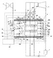
- FIG. 1 is a schematic configuration diagram showing an exhaust heat recovery boiler, a control method for an exhaust heat recovery boiler, and a control system for an exhaust heat recovery boiler constituting a first embodiment of a combined cycle power plant using them.
- FIG. 1 is a system configuration diagram showing an embodiment of an exhaust heat recovery boiler of the present invention, an exhaust heat recovery boiler control method, and a combined cycle power plant using the exhaust heat recovery boiler
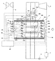
- FIG. 2 is an exhaust heat recovery boiler of the present invention. It is a schematic block diagram which shows the control system of the waste heat recovery boiler which comprises 1st Embodiment of the control method of a waste heat recovery boiler, and the combined cycle power plant using these.
- FIG. 1 shows a system flow of a combined cycle power plant having a gas turbine 3, an exhaust heat recovery boiler 4, a steam turbine 5, a generator 6, and a condenser 7.
- the gas turbine 3 includes a compressor 3 a, a turbine 3 b, a combustor 3 c, and a drive shaft 30.
- the compressor 3a sucks and pressurizes air and supplies it as combustion air to the combustor 3c.
- the combustor 3c mixes and burns the combustion air with fuel to generate high-temperature combustion gas.
- the combustion gas drives the turbine 3 b and drives the compressor 3 b, the steam turbine 5 and the generator 6 through the drive shaft 30.
- the exhaust heat recovery boiler 4 exchanges heat between the exhaust gas 1 from the gas turbine 3 and the feed water 2C to generate steam 2A, and supplies the steam 2A to the steam turbine 5.
- the feed water 2 ⁇ / b> C supplied to the exhaust heat recovery boiler 4 is stored in the lower part of the condenser 7 and is pumped to the exhaust heat recovery boiler 4 by the feed water pump 8.
- the exhaust gas 1 from the gas turbine 3 is discharged into the atmosphere from a stack (not shown) after heat exchange with the feed water 2C.
- the steam turbine 5 is connected to the gas turbine 3 by a drive shaft 30 and is driven by the introduction of the steam 2A generated in the exhaust heat recovery boiler 4.
- the steam 2 ⁇ / b> B that has performed work in the steam turbine 5 is condensed in the condenser 7, and then returned to the exhaust heat recovery boiler 4 by the feed water pump 8.
- the generator 6 is connected to the steam turbine 5 by a drive shaft 30, is driven by the gas turbine 3 and the steam turbine 5, and sends the generated power to the system.
- the exhaust heat recovery boiler 4 includes a box-shaped casing 4A in which the exhaust gas 1 from the gas turbine 3 is introduced and the outer peripheral portion is covered with a heat insulating material, and an exhaust gas flow path portion 4B in the casing 4A.
- the first and second partition plates 14A and 14B divided into three in the width direction, the first exhaust gas flow path 4Ba formed by the first partition plate 14A and the casing 4A, the first partition plate 14A and the second partition plate 14B.
- First to third steam generation units 10a to 10c provided respectively, and first to third exhaust gas inflow adjusting means 11a to 11a provided at the respective upstream inlets of the first to third exhaust gas passages 4Ba to 4Bc. 11c , Generated by first to third exhaust gas outflow adjusting means 12a to 12c provided at each outlet on the downstream side of the first to third exhaust gas passages 4Ba to 4Bc, and the first to third steam generators 10a to 10c.
- the first to third steam control valves 13a to 13c for adjusting the flow rate of the supplied steam to the steam turbine 5 are provided.
- the casing 4A has openings at both ends, the opening on one side forms an exhaust gas inflow part 18 for introducing the exhaust gas 1 from the gas turbine 3, and the other opening exchanges heat with the steam generating part.
- the exhaust gas outflow part 19 which discharges the exhaust gas after having been formed is formed.
- the exhaust heat recovery boiler 4 is configured by the first to third units 40a to 40c divided into three in the width direction in the exhaust gas passage portion 4B in the casing 4A, and the exhaust gas passage portion 4B. From the upstream side toward the downstream side, the first unit 40a is disposed on the leftmost side, the second unit 40b is disposed on the center, and the third unit 40c is disposed on the rightmost side.
- Each unit includes an independent exhaust gas flow path, a steam generation unit, an exhaust gas inflow adjusting means, an exhaust gas outflow adjusting means, and a steam control valve.
- the water supply is supplied from the water supply pump 8 through the water supply pipes to the steam generators 10a to 10c of the first to third units 40a to 40c.
- steam is supplied to the turbine 5 from the steam generators 10a to 10c of the first to third units 40a to 40c via the main steam pipes.
- the first to third steam control valves 13a to 13c are provided in each main steam pipe.
- Each main steam pipe is provided with temperature sensors 15a to 15c for detecting the temperature of the steam generated by the steam generators 10a to 10c.
- the temperature sensors 15a to 15c output the detected temperatures of the steam generated by the respective steam generation units to the control device 20 described later.
- the exhaust gas inflow part 18 on the upstream side of the exhaust gas flow path part 4B of the exhaust heat recovery boiler 4 is connected to an exhaust gas duct 9 into which the exhaust gas 1 from the gas turbine 3 is introduced.
- the exhaust gas duct 9 is provided with a temperature sensor 16 that detects the exhaust gas temperature of the gas turbine 3 and a flow rate sensor 17 that detects the flow rate of the exhaust gas 1.
- the temperature sensor 16 outputs the detected exhaust gas temperature, and the flow sensor 17 outputs the detected exhaust gas flow rate to the control device 20 described later.
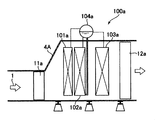
- FIG. 3 is a longitudinal side view showing the exhaust heat recovery boiler according to the present invention, the exhaust heat recovery boiler control method, and the apparatus configuration of the exhaust heat recovery boiler constituting the first embodiment of the combined cycle power plant using these. It is.
- the second unit 40b and the third unit 40c are configured in the same manner as the first unit 40a, and the same members are designated by subscripts “a” to “b” or the subscripts of the respective members of the first unit 40a. The description will be omitted as it is shown in place of “c”.
- the first steam generation unit 10a includes, for example, a superheater 101a, an evaporator 102a, and a economizer 103a arranged in order from the upstream side along the flow direction of the exhaust gas 1, and an upper portion of the casing 4A. It is comprised with the natural-circulation boiler horizontally installed in the heat exchanger tube which has arrange
- the water supply is supplied to the economizer 103a through the water supply pipe 8 by the water supply pump 8, preheated to a predetermined temperature, and then supplied to the steam drum 104a.
- the feed water supplied to the steam drum 104a is circulated and heated in the order of the evaporator 102a and the steam drum 104a, and separated into water and steam by the steam drum 104a.
- the water is circulated again in the evaporator 102a and the steam drum 104a, but the steam is sent to the superheater 101a, where it is further heated, and then supplied to the steam turbine 5 from the main steam pipe.
- the first exhaust gas inflow adjusting means 11a adjusts the flow rate of the exhaust gas 1 flowing from the gas turbine 3 into the first steam generation unit 10a, and is disposed, for example, on the inlet side of the partition plate 14A.
- the damper 110a and the damper drive unit 115a can adjust the inflow amount of the exhaust gas 1 in the first exhaust gas passage 4Ba by the damper opening. As shown in FIG. 2, when the opening degree of the damper 110 a is controlled at a position parallel to the flow direction of the exhaust gas 1, the exhaust gas inflow amount becomes maximum, and the damper 110 a of the damper 110 a is crossed with the flow direction of the exhaust gas 1. When the opening degree is controlled, the inflow of the exhaust gas 1 is blocked.
- the first exhaust gas outflow adjusting means 12a adjusts the flow rate of the exhaust gas 1 flowing out from the first steam generation unit 10a.
- the first exhaust gas outflow adjustment means 12a is disposed on the outlet side of the partition plate 14A and is exhaust gas in the first exhaust gas passage 4Ba. 1 is configured by a damper 120a capable of adjusting the outflow amount of 1 by the damper opening degree and a drive part 125a of the damper. As shown in FIG. 2, when the opening degree of the damper 120 a is controlled at a position parallel to the flow direction of the exhaust gas 1, the exhaust gas outflow amount becomes maximum, and the damper 120 a is positioned at a position intersecting the flow direction of the exhaust gas 1. When the opening degree is controlled, the outflow of the exhaust gas 1 is blocked.
- the first steam control valve 13a adjusts the supply flow rate of the steam generated by the first steam generation unit 10a to the steam turbine 5, and can adjust the steam flow rate in the main steam pipe by its opening, for example. It is comprised with the adjustment valve and the drive part of the adjustment valve.
- Openings of the dampers 110a and 120a constituting the first exhaust gas inflow adjusting means 11a and the first exhaust gas outflow adjusting means 12a are driven by the drive portions 115a and 125a of the dampers that receive a command signal from the control device 20.
- the valve opening degree of the first steam control valve 13a is controlled by a drive unit that receives a command signal from the control device 20.
- the heat capacity on the heat receiving side is changed in accordance with the amount of supplied heat, so that the generated steam can be quickly brought to a desired temperature. It is characterized by allowing it to rise. That is, the heat receiving volume and the water supply amount in the exhaust heat recovery boiler 4 on the heat receiving side are changed according to the heat amount of the exhaust gas 1 from the gas turbine 3 that is the supply heat amount. Specifically, during the period in which the exhaust gas 1 has a low calorific value in the plant startup process, high-temperature steam can be generated quickly by controlling the flow of the exhaust gas 1 so as to heat only a part of the steam generator. Can do. As a result, the startup time of the combined cycle power plant can be shortened.
- FIG. 4 is a control block diagram showing the exhaust heat recovery boiler of the present invention, the control method of the exhaust heat recovery boiler, and the control device constituting the first embodiment of the combined cycle power plant using these.
- the same reference numerals as those shown in FIG. 1 and FIG. 2 are the same parts, and detailed description thereof will be omitted.
- the exhaust gas inflow adjusting means 11a to 11c and the exhaust gas outflow adjusting means 12a to 12c are heated so that only a part of the steam generating parts are heated.
- a control device 20 for controlling the valve opening degrees of the steam control valves 13a to 13c for adjusting the supply flow rate of the steam generated in the steam generating section to the steam turbine 5.
- the control device 20 calculates the heat capacity on the heat receiving side from the supplied heat amount and outputs an exhaust gas flow rate command signal to each unit, and whether there is a ventilation condition of steam generated by the steam generation unit to the turbine 3
- the steam flow rate calculation unit 22 that outputs a steam flow rate command signal to each unit and the exhaust gas flow rate command signal are input, and the first to third exhaust gas inflow adjusting means 11a to 11c and the first to third exhaust gas outflows are input.
- the first to third exhaust gas flow control output units 23a to 23c for outputting the command signals to the adjusting means 12a to 12c and the steam flow rate command signals are input, and the commands to the first to third steam control valves 13a to 13c are input.
- First to third steam flow rate control output units 24a to 24c for outputting signals.
- the exhaust gas flow calculation unit 21 detects the temperature sensor 16 that measures the temperature of the exhaust gas 1 of the gas turbine 3 introduced into the casing 4A, and the exhaust gas of the gas turbine 3 that is introduced into the casing 4A.
- the detection signal of the flow sensor 17 that measures the flow rate of 1 the detection signals of the temperature sensors 15a to 15c that measure the temperature of the steam generated in each steam generator, and the start / stop command signal of the combined cycle power plant are input To do.
- the start / stop command signal may be a known method such as determining whether or not the signal indicating the operation mode input from the host controller or the like has a value indicating the start of the start mode. good.
- the exhaust gas flow calculation unit 21 calculates the heat capacity on the heat receiving side from the exhaust gas temperature as the supply heat amount and the start / stop command signal of the combined cycle power plant, so that the calculated heat capacities are obtained. 3. Output command signals to the exhaust gas flow control output units 23a to 23c.
- the first exhaust gas flow control output unit 23a outputs a drive command corresponding to the command signal to each of the drive units 115a and 125a of the dampers 110a and 120a constituting the first exhaust gas inflow adjustment unit 11a and the first exhaust gas outflow adjustment unit 12a. .
- the second exhaust gas flow control output unit 23b sends a drive command corresponding to the command signal to each of the drive units 115b and 125b of the dampers 110b and 120b constituting the second exhaust gas inflow adjustment unit 11b and the second exhaust gas outflow adjustment unit 12b.
- the third exhaust gas flow control output unit 23c sends a drive command corresponding to the command signal to each of the drive units 115c and 125c of the dampers 110c and 120c constituting the third exhaust gas inflow adjustment unit 11c and the third exhaust gas outflow adjustment unit 12c. Output.
- the opening degrees of the dampers 110a to 110c constituting the first to third exhaust gas inflow adjusting means 11a to 11c and the dampers 120a to 120c constituting the first to third exhaust gas outflow adjusting means 12a to 12c are controlled. Since the unit into which the exhaust gas 1 is introduced is selectively controlled, the heat capacity on the heat receiving side can be controlled.
- the steam flow rate calculation unit 22 inputs detection signals from the temperature sensors 15a to 15c that measure the temperature of the steam generated by each steam generation unit and a start / stop command signal for the combined cycle power plant, and is generated by the steam generation unit.
- the presence / absence of a condition for venting the steam to the steam turbine 5 is calculated, and command signals are output to the first to third steam flow rate control output units 24a to 24c so as to vent from the unit that satisfies the ventilation condition.
- the first steam flow control output unit 24a outputs a drive command corresponding to the command signal to the drive unit of the first steam control valve 13a, and similarly, the second steam flow control output unit 24b and the third steam flow control output unit.
- 24c outputs the drive command according to a command signal to each drive part of the 2nd and 3rd steam control valves 13b and 13c.
- the opening degree of each of the first to third steam control valves 13a to 13c is controlled, and the unit for supplying the generated steam is selectively controlled. Therefore, the steam generated at an early timing is supplied to the steam turbine 5. Can supply. As a result, the plant startup time can be shortened.
- FIG. 5 is a flowchart showing an exhaust heat recovery boiler of the present invention, an exhaust heat recovery boiler control method, and a start-up process flow of the control device constituting the first embodiment of the combined cycle power plant using these. .
- the control device 20 determines whether or not the plant is in the starting process (step S1). As a determination method, for example, the determination may be made based on whether or not the signal indicating the operation mode input from the host controller or the like has a value indicating the start of the start mode. When it is determined that the plant is in the starting process, the process proceeds to (Step S2), and otherwise, the process returns to (Step S1). Before starting the plant, the dampers 110a to 110c constituting the first to third exhaust gas inflow adjusting means 11a to 11c and the dampers 120a to 120c constituting the first to third exhaust gas outflow adjusting means 12a to 12c shown in FIG. 120c and the first to third steam control valves 13a to 13c are all in a closed state, and the flow path form through which the exhaust gas 1 from the gas turbine 3 flows into each steam generation section can be expressed as 000.
- Control device 20 determines whether or not the exhaust gas temperature is equal to or higher than a predetermined value (step S2). Specifically, the exhaust gas flow calculation unit 21 of the control device 20 compares and determines the temperature of the exhaust gas 1 of the gas turbine 3 taken from the temperature sensor 1 and a predetermined specified value gt1.
- the specified value gt1 is a value of the exhaust gas temperature that can raise the temperature of the steam generating unit 10b, and may be set by bias-adding a predetermined temperature based on the temperature of the steam generating unit 10b at this time, for example. good. If the exhaust gas temperature is equal to or higher than the specified value gt1, the process proceeds to (Step S4), and otherwise, the process proceeds to (Step S3).
- the control device 20 When the exhaust gas temperature is less than the specified value gt1, the control device 20 causes the exhaust gas 1 from the gas turbine 3 to flow into the first steam generation unit 10a and the third steam generation unit 10c, and to the second steam generation unit 10b.
- a command signal is output to the first to third exhaust gas inflow adjusting means 11a to 11c and the first to third exhaust gas outflow adjusting means 12a to 12c so as to obtain a flow path configuration (flow path configuration 101) that does not flow (step 101).
- the dampers 110a and 110c and the first and third exhaust gas outflow adjusting means 12a and 12c constituting the first and third exhaust gas flow adjusting means 11a and 11c in the closed state are provided so that the flow path form 101 is obtained.
- a command signal for opening the dampers 120a and 120c constituting the command, and a command signal for maintaining the closed state of the damper 110b constituting the second exhaust gas flow adjusting means 11b and the damper 12b constituting the second exhaust gas outflow adjusting means 12b Is output to the drive units 115a to 115c and 125a to 125c of each damper. This is done in order to prevent the low temperature exhaust gas 1 from lowering the temperature of the second steam generation unit 10b to be heated first. Note that the processing returns to (step S2) after execution of the processing of (step S3).
- step S2 when the exhaust gas temperature becomes equal to or higher than the specified value gt1, the control device 20 causes the exhaust gas 1 from the gas turbine 3 to flow into the second steam generation unit 10b, and the first steam generation unit 10a and the first steam generation unit 10a.
- the first to third exhaust gas inflow adjusting means 11a to 11c and the first to third exhaust gas outflow adjusting means 12a to 12c so as to have a flow path configuration (flow path configuration 010) that does not flow into the 3 steam generation section 10c.
- a command signal is output to (step S4).
- a command signal for closing 120a and 120c, and a command signal for opening the damper 110b constituting the second exhaust gas flow adjusting means 11b and the damper 120b constituting the second exhaust gas outflow adjusting means 12b are provided for each damper.
- the heat receiving part that receives the heat of the exhaust gas 1 is only the second steam generation part 10b (the heat capacity is reduced), so that high-temperature steam can be generated quickly.
- the control device 20 determines whether or not the temperature of the steam generated by the second steam generation unit 10b is equal to or higher than a predetermined value st1 (step S5). Specifically, in the exhaust gas flow calculation unit 21 of the control device 20, the temperature of the steam of the second steam generation unit 10b taken from the temperature sensor 15b is compared with a predetermined specified value st1.
- the prescribed value st1 is, for example, a steam temperature obtained by subtracting a predetermined value from the steam temperature that satisfies the ventilation condition to the steam turbine 5.
- the process proceeds to (Step S7), and otherwise, the process returns to (Step S5).
- Step S5 it may be determined whether the exhaust gas 1 is in a state in which the main body temperature (for example, the internal metal temperature) of the second steam generation unit 10b can be raised. For example, the determination may be made based on whether the temperature of the exhaust gas 1 is higher than a predetermined value compared with a temperature (for example, an internal metal temperature) representing the state of the second steam generation unit 10b.
- the main body temperature for example, the internal metal temperature
- the determination may be made based on whether the temperature of the exhaust gas 1 is higher than a predetermined value compared with a temperature (for example, an internal metal temperature) representing the state of the second steam generation unit 10b.
- control device 20 determines whether or not the temperature of the steam generated by the second steam generating unit 10b is equal to or higher than a predetermined specified value st2 (step S6). Specifically, in the steam flow rate calculation unit 22 of the control device 20, the temperature of the steam of the second steam generation unit 10b taken from the temperature sensor 15b is compared with a predetermined specified value st2.
- the specified value st2 is, for example, a steam temperature that satisfies a ventilation condition to the steam turbine 5. If the steam temperature is equal to or higher than the specified value st2, the process proceeds to (Step S9), and otherwise, the process returns to (Step S6).
- Step S6 it may be determined whether or not the steam generated by the second steam generation unit 10b has approached a state in which the steam can be vented to the steam turbine 5.
- this criterion may be configured by the following items or a combination thereof.
- the generated steam temperature is higher than a predetermined value by comparison with a temperature representing the state of the steam turbine 5 (for example, a metal temperature inside the steam turbine or a main steam temperature).
- the generated steam pressure is higher than a predetermined specified value as compared with the internal pressure of the steam turbine 5. ⁇
- the generated steam flow is higher than the specified value.
- Step S5 when the steam temperature is equal to or higher than the specified value st1, the control device 20 causes the exhaust gas 1 from the gas turbine 3 to flow into the first steam generation unit 10a and the second steam generation unit 10b, and the third The first to third exhaust gas inflow adjusting means 11a to 11c and the first to third exhaust gas outflow adjusting means 12a to 12c are commanded so as to have a flow path configuration (flow path configuration 110) that does not flow into the steam generation section 10c. A signal is output (step S7).
- a command signal for closing the damper 110c constituting the third exhaust gas flow adjusting means 11c and the damper 120c constituting the third exhaust gas outflow adjusting means 12c so as to obtain the flow path form 110 and the first And a command signal for opening the dampers 110a, 110b constituting the second exhaust gas flow adjusting means 11a, 11b and the dampers 120a, 120b constituting the first and second exhaust gas outflow adjusting means 12a, 12b.
- the heat receiving part that receives the heat of the exhaust gas 1 is added with the first steam generating part 10a only from the second steam generating part 10b, and the heat capacity is increased, so that the steam flow supplied to the steam turbine 5 is increased. be able to.
- the control device 20 determines whether or not the temperature of the steam generated by the first steam generator 10a is equal to or higher than a predetermined value st1 (step S8). Specifically, in the exhaust gas flow calculation unit 21 of the control device 20, the temperature of the steam of the first steam generation unit 10a taken from the temperature sensor 15a is compared with a predetermined specified value st1. Here, the specified value st1 is the same as (step S5). If the steam temperature is equal to or higher than the specified value st1, the process proceeds to (Step S11), and otherwise, the process returns to (Step S7).
- step S6 when the steam temperature is equal to or higher than the specified value st2, the control device 20 causes only the generated steam from the second steam generation unit 10b to flow into the steam turbine 5, and the first and third steam generation units 10a. , 10c, command signals are output to the first to third steam control valves 13a to 13c so as not to flow into the steam turbine 5 (step S9).
- step S9 command signals are output to the first to third steam control valves 13a to 13c so as not to flow into the steam turbine 5.
- the control device 20 determines whether or not the temperature of the steam generated by the first steam generator 10a is equal to or higher than a predetermined value st2 (step S10). Specifically, the steam flow rate calculation unit 22 of the control device 20 compares and determines the steam temperature of the first steam generation unit 10a taken from the temperature sensor 15a and a predetermined specified value st2. Here, the specified value st2 is the same as (Step S6). If the steam temperature is equal to or higher than the specified value st2, the process proceeds to (Step S12), and otherwise, the process returns to (Step S9).
- step S8 when the steam temperature is equal to or higher than the specified value st1, the control device 20 causes the exhaust gas 1 from the gas turbine 3 to be converted into the first steam generation unit 10a, the second steam generation unit 10b, and the third steam generation unit 10c.
- Command signals are output to the first to third exhaust gas inflow adjusting means 11a to 11c and the first to third exhaust gas outflow adjusting means 12a to 12c so as to be in a flow path form (flow path form 111) flowing into the Step S11).
- the dampers 110a to 110c constituting the first to third exhaust gas flow adjusting means 11a to 11c and the dampers constituting the first to third exhaust gas outflow adjusting means 12a to 12c so as to obtain the flow path form 111.
- Command signals for opening 120a to 110c are output to the drive units 115a to 115c and 125a to 125c of the respective dampers.
- the heat receiving part that receives the heat of the exhaust gas 1 is added with the third steam generating part 10c from the first and second steam generating parts 10a, 10b, and the heat capacity is increased.
- the flow rate can be increased. Note that after executing the process of (Step S11), the process proceeds to return.
- step S10 when the steam temperature is equal to or higher than the specified value st2, the control device 20 causes only the steam generated from the first steam generator 10a and the second steam generator 10b to flow into the steam turbine 5, A command signal is output to the first to third steam control valves 13a to 13c so that the steam generated from the third steam generating section 10c does not flow into the steam turbine 5 (step S12).
- the high-temperature steam generated by the first steam generation unit 10 a and the second steam generation unit 10 b is vented to the steam turbine 5.
- the control device 20 determines whether or not the temperature of the steam generated by the third steam generator 10c is equal to or higher than a predetermined value st2 (step S13). Specifically, the steam flow rate calculation unit 22 of the control device 20 compares and determines the steam temperature of the third steam generation unit 10c taken from the temperature sensor 15c and a predetermined specified value st2. Here, the specified value st2 is the same as (Step S6). If the steam temperature is equal to or higher than the specified value st2, the process proceeds to (Step S13), and otherwise, the process returns to (Step S12).
- Step S10 when the steam temperature is equal to or higher than the specified value st2, the control device 20 determines that the steam generated from the first steam generating unit 10a, the second steam generating unit 10b, and the third steam generating unit 10c is a steam turbine.
- the command signal is output to the first to third steam control valves 13a to 13c so as to flow into the flow (step S14).
- the high-temperature steam generated by the first steam generation unit 10a, the second steam generation unit 10b, and the third steam generation unit 10c is vented to the steam turbine 5. Note that after executing the processing of (Step S14), the process proceeds to return.
- FIG. 6 is a flowchart showing a stop processing flow of the control device constituting the first embodiment of the exhaust heat recovery boiler, the exhaust heat recovery boiler control method of the present invention, and the combined cycle power plant using them. .
- the control device 20 determines whether or not the plant is in a stop process (step S21).
- the determination method may be a known method such as determination from the operation mode. If it is determined that the plant is in the process of stopping, the process proceeds to (Step S22) and (Step S25), and otherwise, the process returns to (Step S21).
- the dampers 110a to 110c constituting the first to third exhaust gas inflow adjusting means 11a to 11c and the damper 120a constituting the first to third exhaust gas outflow adjusting means 12a to 12c shown in FIG. ⁇ 120c and the first to third steam control valves 13a to 13c are all open, and the flow path form through which the exhaust gas 1 from the gas turbine 3 flows into each steam generation section can be expressed as 111.
- Control device 20 determines whether or not the exhaust gas temperature is equal to or lower than a predetermined value (step S22). Specifically, the exhaust gas flow calculation unit 21 of the control device 20 compares and determines the temperature of the exhaust gas 1 of the gas turbine 3 taken from the temperature sensor 1 and a predetermined specified value gt2.
- the specified value gt2 is a value at which the exhaust gas lowers the main body temperature (for example, internal metal temperature) of the steam generation unit 10b. For example, it may be set by subtracting a predetermined temperature based on the body temperature of the steam generation unit 10b at this time. If the exhaust gas temperature is less than or equal to the specified value gt2, the process proceeds to (Step S24), and otherwise, the process proceeds to (Step S23).
- the control device 20 When the exhaust gas temperature exceeds the specified value gt2, the control device 20 causes the exhaust gas 1 from the gas turbine 3 to flow into the first steam generation unit 10a, the second steam generation unit 10b, and the third steam generation unit 10c.
- Command signals are output to the first to third exhaust gas inflow adjusting means 11a to 11c and the first to third exhaust gas outflow adjusting means 12a to 12c so as to maintain the state of (flow path form 111) (step S23). . In addition, it returns to (step S22) after execution of the process of (step S23).
- step S22 when the exhaust gas temperature becomes equal to or lower than the specified value gt2, the control device 20 causes the exhaust gas 1 from the gas turbine 3 to flow into the first and third steam generation units 10a and 10c and the second steam.
- a command signal is sent to the first to third exhaust gas inflow adjusting means 11a to 11c and the first to third exhaust gas outflow adjusting means 12a to 12c so that the flow path form (flow path form 101) does not flow into the generator 10b.
- Is output step S24.
- a command signal for opening 120a, 120c and a command signal for closing the damper 110b constituting the second exhaust gas flow adjusting means 11b and the damper 120b constituting the second exhaust gas outflow adjusting means 12b are provided for each damper. Output to the driving units 115a to 115c and 125a to 125c. As a result, the inflow of the exhaust gas 1 to the second steam generation unit 10b is blocked, and the main body temperature of the second steam generation unit 10b is prevented from being lowered. As a result, the activation time at the next activation can be shortened. After executing (Step S24), the process proceeds to (Step S28).
- the control device 20 determines that the temperature of the steam generated by the first to third steam generation units 10a to 10c is a predetermined specified value st3. It is determined whether it is below (step S25). Specifically, the steam flow rate calculation unit 22 of the control device 20 compares the steam temperatures of the first to third steam generation units 10a to 10c taken from the temperature sensors 15a to 15c with a predetermined specified value st3. to decide.
- the specified value st3 is, for example, a steam temperature obtained by adding a predetermined value from the steam temperature that satisfies the ventilation condition to the steam turbine 5. If the steam temperature of any of the fetched first to third steam generators 10a to 10c is equal to or lower than the specified value st3, the process proceeds to (Step S26). Otherwise, the process returns to (Step S25).
- Step S25 When the steam temperature of any of the first to third steam generation units 10a to 10c is equal to or less than the specified value st3 in (Step S25), the control device 20 sends the generated steam from the corresponding steam generation unit to the steam turbine 5. A closing command is output to the steam control valve of the corresponding unit so as not to flow in (step S26). As a result, the supply of the steam whose temperature has decreased in the steam generation section to the steam turbine 5 is stopped.
- the control device 20 determines whether or not all of the first to third steam control valves 13a to 13c are closed (step S27). If all of the first to third steam control valves 13a to 13c are closed, the process proceeds to return, and otherwise returns to (step S25).
- Step S24 After execution of the process, the control device 20 determines whether or not the exhaust gas flow rate is equal to or less than a specified value (step S28). Specifically, the exhaust gas flow calculation unit 21 of the control device 20 compares and determines the flow rate of the exhaust gas 1 of the gas turbine 3 taken in from the flow sensor 17 and a predetermined specified value gt3.
- the specified value gt3 is a value with which it can be determined whether or not the exhaust gas 1 flows into the exhaust heat recovery boiler 4. If the exhaust gas flow rate is less than or equal to the specified value gt3, the process proceeds to (Step S29), and otherwise returns to (Step S24). In (step S28), for example, even if the rotational speed of the gas turbine 3 is detected and is equal to or less than a predetermined value, it is determined that the exhaust gas 1 does not flow into the exhaust heat recovery boiler 4. good.
- step S28 when the exhaust gas flow rate becomes equal to or less than the specified value gt3, the control device 20 uses the flow path configuration in which the exhaust gas 1 from the gas turbine 3 does not flow into the first to third steam generation units 10a to 10c ( A command signal is output to the first to third exhaust gas inflow adjusting means 11a to 11c and the first to third exhaust gas outflow adjusting means 12a to 12c so as to obtain the flow path form 000) (step S29). Specifically, the dampers 110a to 110c constituting the first to third exhaust gas flow adjusting means 11a to 11c and the dampers constituting the first to third exhaust gas outflow adjusting means 12a to 12c so as to obtain the flow path form 000.
- Command signals for closing 120a to 120c are output to the drive units 115a to 115c and 125a to 125c of the respective dampers.
- the inflow and outflow of the exhaust gas 1 to all the steam generation units 10a to 10c are blocked, and the main body temperature of all the steam generation units 10a to 10c is prevented from being lowered.
- the activation time at the next activation can be shortened.
- the exhaust heat recovery boiler 4 is moved in the inflow direction of the exhaust gas 1.
- it is divided into a plurality of steam generators in parallel, and it is configured to heat a part of the plurality of steam generators at the start of startup, so the steam temperature rises to a predetermined temperature in a short time it can.
- the plant startup time can be shortened.
- the control method of a waste heat recovery boiler, and the combined cycle power plant using these, heat capacity per steam generation part 1 unit Therefore, the drum can be downsized, and the thermal stress and thermal deformation of the drum can be reduced. As a result, the restriction on the conventional exhaust gas temperature rise rate can be relaxed, so that the plant start-up time can be shortened.
- the exhaust heat recovery boiler control method of the present invention and the combined cycle power plant using them, the entire exhaust heat recovery boiler 4 is heated in the process of starting the plant.
- the heat capacity per steam generator is reduced by dividing the exhaust heat recovery boiler 4 into a plurality of parallel steam generators, and limited to a part of the steam generators at the start of startup. Since the heating is performed, the steam temperature can be raised to a predetermined temperature in a short time. As a result, since the steam supply to the steam turbine 5 can be accelerated, the plant startup time is shortened.
- the control method of a waste heat recovery boiler, and the combined cycle power plant using these, the 2nd steam generation part 10b used at the time of starting is used. Since it is arranged between the other first and third steam generators 10a, 10c to reduce the heat dissipation after the stop, the second steam generator 10b can be maintained at a high temperature in the plant stop state. As a result, it is possible to generate steam earlier than before when starting up next time.
- the heat insulating material as a constituent member is also included with the steam generating unit.
- the steam generating part inside the exhaust heat recovery boiler 4 is sequentially heated, so that the heating of the heat insulating material, which is also the object of heating, can be delayed.
- the control method of a waste heat recovery boiler, and the combined cycle power plant using these it is several in width direction with respect to the flow direction of waste gas. Since the exhaust gas flow path is provided and each flow path is provided with a unit having a steam generation unit, the capacity per unit of the steam generation unit (unit) is reduced compared to the conventional method, and the drum provided in the steam generation unit Can be miniaturized. By reducing the size of the drum, thermal stress and thermal deformation can be reduced, so that the life of the equipment can be extended and the exhaust gas temperature rise rate that has been limited in the past can be increased. As a result, the plant startup time can be further shortened.
- the order of using the steam generation unit at the time of starting the plant is not limited to the example of the present embodiment.
- FIG. 7 is a schematic configuration diagram showing an exhaust heat recovery boiler according to the present invention, an exhaust heat recovery boiler control method, and a control system for an exhaust heat recovery boiler constituting a second embodiment of a combined cycle power plant using them. It is.
- FIG. 7 the same reference numerals as those shown in FIG. 1 to FIG.
- the exhaust gas flow path of each unit is provided with one damper as exhaust gas inflow means and one damper as exhaust gas outflow means.
- the second embodiment is different in that two dampers are disposed as exhaust gas inflow means and two dampers are disposed as exhaust gas outflow means in the width direction of the exhaust gas flow path of each unit.
- the dampers are arranged in a plane perpendicular to the exhaust gas flow so that the direction of each damper intersects the exhaust gas flow at a right angle while the damper is closed.
- Other waste heat recovery boilers and facilities constituting the combined cycle power plant are the same as those in the first embodiment.
- each damper when the opening degree of these dampers is controlled to a position parallel to the flow direction of the exhaust gas 1, the exhaust gas inflow amount becomes maximum and intersects the flow direction of the exhaust gas 1.
- the opening degree of these dampers is controlled to the position, the inflow of the exhaust gas 1 is blocked. Therefore, the length in the width direction of each damper may be about half of the exhaust gas passage width.
- each damper can be disposed at a location closer to the steam generating section, and therefore the length of the exhaust gas flow path of each unit can be shortened. As a result, the unit can be further downsized.
- the exhaust heat recovery boiler control method of the present invention and the combined cycle power plant using them, the same effects as those of the first embodiment described above. Can be obtained. Moreover, since the length of the exhaust gas flow path can be shortened, the unit including the steam generation unit and the exhaust heat recovery boiler can be further reduced in size.
- FIG. 8 is a schematic configuration diagram showing an exhaust heat recovery boiler according to the present invention, an exhaust heat recovery boiler control method, and a control system for an exhaust heat recovery boiler constituting a third embodiment of a combined cycle power plant using these. It is.
- FIG. 8 the same reference numerals as those shown in FIG. 1 to FIG.
- the dampers are closed in the width direction of the exhaust gas flow path of each unit.
- the dampers are arranged in a plane perpendicular to the exhaust gas flow so that the direction of each damper intersects the exhaust gas flow at a right angle.
- the two dampers as the exhaust gas inflow means in the steam generation units 10a and 10c other than the center are in the state in which the exhaust gas flows while the dampers are closed. It is different in that it is arranged so that it intersects at an angle rather than at right angles.
- Other waste heat recovery boilers and facilities constituting the combined cycle power plant are the same as those in the second embodiment.
- the damper 110b located at the center in the width direction of the exhaust gas passage portion 4B is provided. It arrange
- the exhaust heat recovery boiler control method of the present invention and the combined cycle power plant using them, the same effects as those of the first embodiment described above. Can be obtained.
- the dampers 110a and 110c constituting the first and third exhaust gas inflow means 11a and 11c are closed and the damper 110b constituting the second exhaust gas inflow means 11b is opened,
- the pressure loss of the exhaust gas in the heat recovery boiler 4 as a whole can be reduced.
Landscapes
- Engineering & Computer Science (AREA)
- Chemical & Material Sciences (AREA)
- Combustion & Propulsion (AREA)
- Mechanical Engineering (AREA)
- General Engineering & Computer Science (AREA)
- Engine Equipment That Uses Special Cycles (AREA)
Description
本発明は、排熱回収ボイラ、排熱回収ボイラの制御方法、及びこれを用いたコンバインドサイクル発電プラントに関する。
近年、化石資源保全のため、風力や太陽光などの再生可能エネルギを用いた発電設備の増加が見込まれている。しかし、これらの再生可能エネルギは天候や季節により大きく変動するので、これらを用いた発電設備の電力量も、同様に変動してしまう。
このような電力量の変動をいち早く補い、電力系統を安定化できる発電設備として、短時間での起動が可能なコンバインドサイクル発電プラントがある。コンバインドサイクル発電プラントは、ガスタービンから排出される高温の排ガスを熱源として、給水を沸騰させて蒸気を得るとともに、この蒸気を蒸気タービンに供給する排熱回収ボイラを備えている。起動時間を短縮化するために、プラント起動時に排熱回収ボイラからより早いタイミングで蒸気を発生させることを目的として、複数のガスタービン、排熱ボイラ(排熱回収ボイラ)、蒸気タービンからなる発電プラントにおいて、前記排熱ボイラ(排熱回収ボイラ)より前記蒸気タービンへ連絡する主蒸気管と同一発電プラント内の他の排熱ボイラ(排熱回収ボイラ)の主蒸気管との間に暖機連絡管を設けたことを特徴とするものがある(例えば、特許文献1参照)。
上述した発電プラントであれば、運転中の他の排熱ボイラ(排熱回収ボイラ)から、起動しようとする排熱ボイラ(排熱回収ボイラ)と蒸気タービンとを連結する主蒸気管を暖機できる。このことにより、従来発生していた、主蒸気管暖機に起因する蒸気タービン入口における蒸気温度の低下を防止できるので、新たに起動する蒸気タービンの速やかな出力上昇が可能になる。この結果、発電プラントの起動時間を短縮化できる。
しかし、上述した発電プラントは、外部熱源である他の排熱ボイラ(排熱回収ボイラ)を必要とするので、同一発電プラント内の全ての排熱ボイラ(排熱回収ボイラ)が停止している場合に、最初の発電プラントを起動する場合(外部熱源が無い場合)には、起動時間を短縮化することは難しい。このような、外部熱源を備えない単独のコンバインドサイクル発電プラントの場合においても、起動時間を短縮化する方策が要望されている。
排熱回収ボイラの蒸気発生タイミングを早めることを制限する要因は以下のようなものである。
(1)排熱回収ボイラは、ガスタービンや蒸気タービンと異なり伝熱面積を確保するために熱容量を大きく設計する。このため、温度上昇と蒸気発生に比較的長い時間を要し、蒸気タービンへ供給可能な蒸気条件の成立に時間がかかる。
(2)プラントの起動過程において、ガスタービンの点火の前と直後には、排熱回収ボイラの伝熱面の温度より低温の排ガスが流入する場合がある。このとき、流入する排ガスによって、排熱回収ボイラの温度が一旦低下するので、蒸気発生が遅れてしまう。
(3)ガスタービンの点火後に排ガス温度は上昇するが、ドラム式の排熱回収ボイラの場合、流入する排ガスの温度が急激に上昇すると、ドラムのメタル部分における温度分布が不均一になり、熱応力が増大し熱変形が生じてしまう場合がある。このため、排ガスの温度上昇率に制限を設けて流入する排ガスの急激な温度上昇を防止している。
(4)プラント起動時において、流入する排ガスは、排熱回収ボイラの蒸気発生部を加熱すると同時に、排熱回収ボイラ本体の筺体(ケーシング)を覆う保温材をも加熱する。この保温材の加熱に熱量が使用されるため、蒸気発生部への熱量が減少し、このことにより、蒸気発生部での温度上昇が遅れる。
(1)排熱回収ボイラは、ガスタービンや蒸気タービンと異なり伝熱面積を確保するために熱容量を大きく設計する。このため、温度上昇と蒸気発生に比較的長い時間を要し、蒸気タービンへ供給可能な蒸気条件の成立に時間がかかる。
(2)プラントの起動過程において、ガスタービンの点火の前と直後には、排熱回収ボイラの伝熱面の温度より低温の排ガスが流入する場合がある。このとき、流入する排ガスによって、排熱回収ボイラの温度が一旦低下するので、蒸気発生が遅れてしまう。
(3)ガスタービンの点火後に排ガス温度は上昇するが、ドラム式の排熱回収ボイラの場合、流入する排ガスの温度が急激に上昇すると、ドラムのメタル部分における温度分布が不均一になり、熱応力が増大し熱変形が生じてしまう場合がある。このため、排ガスの温度上昇率に制限を設けて流入する排ガスの急激な温度上昇を防止している。
(4)プラント起動時において、流入する排ガスは、排熱回収ボイラの蒸気発生部を加熱すると同時に、排熱回収ボイラ本体の筺体(ケーシング)を覆う保温材をも加熱する。この保温材の加熱に熱量が使用されるため、蒸気発生部への熱量が減少し、このことにより、蒸気発生部での温度上昇が遅れる。
本発明は、上述の事柄に基づいてなされたもので、その目的は、早いタイミングで蒸気を発生させて蒸気タービンへ供給可能とし、プラントの起動時間を短縮できる排熱回収ボイラ、排熱回収ボイラの制御方法、及びこれらを用いたコンバインドサイクル発電プラントを提供するものである。
上記課題を解決するために、例えば特許請求の範囲に記載の構成を採用する。本願は、上記課題を解決する手段を複数含んでいるが、その一例を挙げるならば、外部熱源から供給される排ガスと外部から供給される水とを用いて蒸気を発生させる排熱回収ボイラにおいて、両端に開口部を設けた箱型のケーシングと、前記ケーシングの一方側の開口部側に設けた排ガス流入部と、前記ケーシングの他方側の開口部側に設けた排ガス流出部と、前記ケーシングの内部に設けた排ガス流路部と、前記排ガス流路部内に、前記排ガスの流れ方向に対して直交する方向に並列配置した複数の蒸気発生部と、前記複数の蒸気発生部間を区切る仕切り板と、前記排ガスを前記複数の蒸気発生部の全て又は一部に選択的に流入させるように、前記排ガスの流れを調整する調整手段と、前記排熱回収ボイラの起動過程の初期においては、前記排ガスを一部の蒸気発生部へ流入させ、その後前記排ガスを順次、他の蒸気発生部へ流入させるように、前記調整手段を動作させる制御装置とを備えたことを特徴とする。
本発明によれば、排熱回収ボイラを排ガスの流入方向に対して並列する複数の蒸気発生部に分けて、起動開始時に複数の蒸気発生部のうちの一部の蒸気発生部を加熱するように構成したので、蒸気温度を短時間で所定の温度まで上昇できる。この結果、早いタイミングで蒸気を発生させて蒸気タービンへ供給できるので、プラント起動時間を短縮できる。
<第1の実施の形態>
以下、本発明の排熱回収ボイラ及びこれを用いたコンバインドサイクル発電プラントの第1の実施の形態を図1乃至図6を用いて説明する。図1は本発明の排熱回収ボイラ、排熱回収ボイラの制御方法、及びこれを用いたコンバインドサイクル発電プラントの一実施の形態を示すシステム構成図、図2は本発明の排熱回収ボイラ、排熱回収ボイラの制御方法、及びこれらを用いたコンバインドサイクル発電プラントの第1の実施の形態を構成する排熱回収ボイラの制御システムを示す概略構成図である。
以下、本発明の排熱回収ボイラ及びこれを用いたコンバインドサイクル発電プラントの第1の実施の形態を図1乃至図6を用いて説明する。図1は本発明の排熱回収ボイラ、排熱回収ボイラの制御方法、及びこれを用いたコンバインドサイクル発電プラントの一実施の形態を示すシステム構成図、図2は本発明の排熱回収ボイラ、排熱回収ボイラの制御方法、及びこれらを用いたコンバインドサイクル発電プラントの第1の実施の形態を構成する排熱回収ボイラの制御システムを示す概略構成図である。
図1はガスタービン3、排熱回収ボイラ4、蒸気タービン5、発電機6、復水器7、を有するコンバインドサイクル発電プラントのシステムフローを示している。
図1において、ガスタービン3は、圧縮機3a、タービン3b、燃焼器3c、及び駆動軸30から構成されている。圧縮機3aは空気を吸気・加圧し、燃焼用空気として燃焼器3cに供給する。燃焼器3cは、前記燃焼用空気を燃料と混合・燃焼させ、高温の燃焼ガスを発生する。前記燃焼ガスはタービン3bを駆動し、駆動軸30を通して圧縮機3b、蒸気タービン5及び発電機6を駆動する。
図1において、ガスタービン3は、圧縮機3a、タービン3b、燃焼器3c、及び駆動軸30から構成されている。圧縮機3aは空気を吸気・加圧し、燃焼用空気として燃焼器3cに供給する。燃焼器3cは、前記燃焼用空気を燃料と混合・燃焼させ、高温の燃焼ガスを発生する。前記燃焼ガスはタービン3bを駆動し、駆動軸30を通して圧縮機3b、蒸気タービン5及び発電機6を駆動する。
排熱回収ボイラ4は、ガスタービン3からの排ガス1と給水2Cとを熱交換させて蒸気2Aを発生させて、この蒸気2Aを蒸気タービン5へ供給する。排熱回収ボイラ4へ供給する給水2Cは復水器7の下部に貯留されており、給水ポンプ8にて排熱回収ボイラ4へ圧送される。ガスタービン3からの排ガス1は、給水2Cとの熱交換後、図示しないスタックから大気中に放出される。
蒸気タービン5は、駆動軸30によりガスタービン3に接続されていて、排熱回収ボイラ4で発生した蒸気2Aが導入されることで駆動する。蒸気タービン5にて仕事を行った蒸気2Bは、復水器7で復水された後、給水ポンプ8によって、排熱回収ボイラ4に還流される。
発電機6は、駆動軸30により蒸気タービン5に接続されていて、ガスタービン3と蒸気タービン5とによって駆動され、発電した電力を系統へ送る。
次に、排熱回収ボイラ4の構成を説明する。図2に示すように、排熱回収ボイラ4は、ガスタービン3からの排ガス1を導入すると共に外周部を保温材で被覆した箱型のケーシング4Aと、ケーシング4A内の排ガス流路部4Bを幅方向に3分割する第1及び第2仕切り板14A,14Bと、第1仕切り板14Aとケーシング4Aとで形成された第1排ガス流路4Baと、第1仕切り板14Aと第2仕切り板14Bとケーシング4Aとで形成された第2排ガス流路4Bbと、第2仕切り板14Bとケーシング4Aとで形成された第3排ガス流路4Bcと、第1乃至第3排ガス流路4Ba~4Bc内にそれぞれ設けられた第1乃至第3蒸気発生部10a~10cと、第1乃至第3排ガス流路4Ba~4Bcの上流側の各流入口に設けられた第1乃至第3排ガス流入調整手段11a~11cと、第1乃至第3排ガス流路4Ba~4Bcの下流側の各流出口に設けられた第1乃至第3排ガス流出調整手段12a~12cと、第1乃至第3蒸気発生部10a~10cで発生した蒸気の蒸気タービン5への供給流量を調整する第1乃至第3蒸気加減弁13a~13cとを備えている。なお、ケーシング4Aは、両端に開口部を設けていて、一方側の開口部がガスタービン3からの排ガス1を導入する排ガス流入部18を形成し、他方の開口部が蒸気発生部で熱交換した後の排ガスを排出する排ガス流出部19を形成している。
換言すると、排熱回収ボイラ4は、ケーシング4A内の排ガス流路部4Bにおいて、幅方向に3つに分割された第1乃至第3ユニット40a~40cで構成されていて、排ガス流路部4Bの上流側から下流側に向かって一番左に第1ユニット40a、中央に第2ユニット40b、一番右に第3ユニット40cが、それぞれ配置されている。各ユニットは、それぞれ独立した排ガス流路と、蒸気発生部と、排ガス流入調整手段と、排ガス流出調整手段と、蒸気加減弁とを備えている。
第1乃至第3ユニット40a~40cの各蒸気発生部10a~10cには、給水ポンプ8から各給水管を経て給水が供給されている。また、第1乃至第3ユニット40a~40cの各蒸気発生部10a~10cからは、各主蒸気管を介してタービン5へ蒸気が供給されている。第1乃至第3蒸気加減弁13a~13cは各主蒸気管に設けられている。各主蒸気管には、各蒸気発生部10a~10cで生成した蒸気の温度を検出する温度センサ15a~15cが、各々設けられている。温度センサ15a~15cは、検出した各蒸気発生部で生成した蒸気の温度を後述する制御装置20へ出力する。
排熱回収ボイラ4の排ガス流路部4Bの上流側の排ガス流入部18は、ガスタービン3からの排ガス1が導入される排ガスダクト9と接続されている。排ガスダクト9には、ガスタービン3の排ガス温度を検出する温度センサ16と排ガス1の流量を検出する流量センサ17とが設けられている。温度センサ16は検出した排ガス温度を、流量センサ17は検出した排ガス流量を後述する制御装置20へそれぞれ出力する。
ここで、説明の便宜上、第1ユニット40aの構成の概要を図3を用いて説明する。図3は本発明の排熱回収ボイラ、排熱回収ボイラの制御方法、及びこれらを用いたコンバインドサイクル発電プラントの第1の実施の形態を構成する排熱回収ボイラの装置構成を示す縦断側面図である。なお、第2ユニット40bと第3ユニット40cとは、第1ユニット40aと同様に構成されており、同じ部材には第1ユニット40aの各部材の符号の添字を「a」から「b」又は「c」に換えて示すこととして説明を省略する。
第1蒸気発生部10aは、図3に示すように、例えば、排ガス1の流れ方向に沿って、上流側から順に過熱器101a、蒸発器102a、節炭器103aが配置され、ケーシング4Aの上部に蒸気ドラム104aを配置した伝熱管横置きの自然循環ボイラで構成されている。
給水は、給水ポンプ8により給水管を経て節炭器103aに供給され、ここで所定の温度まで予熱された後に蒸気ドラム104aへ供給される。蒸気ドラム104aに供給された給水は、蒸発器102aと蒸気ドラム104aとの順で循環されて加熱され、蒸気ドラム104aで水と蒸気に分離される。水は再度、蒸発器102aと蒸気ドラム104aとで循環されるが、蒸気は、過熱器101aへ送られ、ここでさらに昇温された後、主蒸気管より蒸気タービン5へ供給される。
図2に戻り、第1排ガス流入調整手段11aは、ガスタービン3から第1蒸気発生部10aに流入する排ガス1の流量を調整するものであって、例えば、仕切り板14Aの入口側に配置され、第1排ガス流路4Baにおける排ガス1の流入量をそのダンパ開度で調整可能なダンパ110aとダンパの駆動部115aとで構成されている。図2に示すように、排ガス1の流れ方向と平行な位置にそのダンパ110aの開度を制御したときに、排ガス流入量は最大となり、排ガス1の流れ方向と交差する位置にそのダンパ110aの開度を制御したときに、排ガス1の流入は遮断される。
第1排ガス流出調整手段12aは、第1蒸気発生部10aから流出する排ガス1の流量を調整するものであって、例えば、仕切り板14Aの出口側に配置され、第1排ガス流路4Baにおける排ガス1の流出量をそのダンパ開度で調整可能なダンパ120aとそのダンパの駆動部125aとで構成されている。図2に示すように、排ガス1の流れ方向と平行な位置にそのダンパ120aの開度を制御したときに、排ガス流出量は最大となり、排ガス1の流れ方向と交差する位置にそのダンパ120aの開度を制御したときに、排ガス1の流出は遮断される。
第1蒸気加減弁13aは、第1蒸気発生部10aで発生した蒸気の蒸気タービン5への供給流量を調整するものであって、例えば、主蒸気管における蒸気流量をその開度で調整可能な調整弁とその調整弁の駆動部とで構成されている。
第1排ガス流入調整手段11aと第1排ガス流出調整手段12aとを構成する各ダンパ110a,120aの開度は、制御装置20からの指令信号を受けた各ダンパの駆動部115a,125aが駆動されることで制御される。第1蒸気加減弁13aの弁開度は、制御装置20からの指令信号を受けた駆動部により制御される。
本発明の排熱回収ボイラ及びこれを用いたコンバインドサイクル発電プラントの第1の実施の形態は、供給熱量に応じて受熱側の熱容量を変化させることで、生成する蒸気を速やかに所望の温度まで上昇可能とすることに特徴がある。つまり、供給熱量であるガスタービン3からの排ガス1の熱量に応じて、受熱側である排熱回収ボイラ4における受熱容積と給水量とを変化させている。具体的には、プラント起動過程において排ガス1が低熱量である期間は、一部の蒸気発生部のみを加熱するように、排ガス1の流れを制御することで、高温蒸気を迅速に発生させることができる。この結果、コンバインドサイクル発電プラントの起動時間を短縮できる。
次に、本発明の排熱回収ボイラ及びこれを用いたコンバインドサイクル発電プラントの第1の実施の形態を構成する制御装置について図4を用いて説明する。図4は本発明の排熱回収ボイラ、排熱回収ボイラの制御方法、及びこれらを用いたコンバインドサイクル発電プラントの第1の実施の形態を構成する制御装置示す制御ブロック図である。図4において、図1及び図2に示す符号と、同符号のものは同一部分であるので、その詳細な説明は省略する。
本実施の形態においては、コンバインドサイクル発電プラントの起動時間を短縮するために、一部の蒸気発生部のみを加熱するように排ガス流入調整手段11a~11cの開度と排ガス流出調整手段12a~12cの開度を制御すると共に、蒸気発生部で発生した蒸気の蒸気タービン5への供給流量を調整する蒸気加減弁13a~13cの弁開度を制御する制御装置20を備えている。
制御装置20は、供給熱量から受熱側の熱容量を算出して各ユニットへの排ガス流量指令信号を出力する排ガス流れ演算部21と、蒸気発生部で生成した蒸気のタービン3への通気条件の有無を判断し、各ユニットへの蒸気流量指令信号を出力する蒸気流量演算部22と、排ガス流量指令信号を入力し、第1~第3排ガス流入調整手段11a~11cと第1~第3排ガス流出調整手段12a~12cとへ各指令信号を出力する第1~第3排ガス流れ制御出力部23a~23cと、蒸気流量指令信号を入力し、第1~第3蒸気加減弁13a~13cへ各指令信号を出力する第1~第3蒸気流量制御出力部24a~24cとを備えている。
排ガス流れ演算部21は、図4に示すように、ケーシング4Aに導入されるガスタービン3の排ガス1の温度を計測する温度センサ16の検知信号と、ケーシング4Aに導入されるガスタービン3の排ガス1の流量を計測する流量センサ17の検知信号と、各蒸気発生部で生成した蒸気の温度を計測する温度センサ15a~15cの検知信号と、コンバインドサイクル発電プラントの起動/停止指令信号とを入力する。ここで、起動/停止指令信号は、例えば、上位のコントローラ等から入力される運転モードを表す信号が起動モードの開始を表す値になっているか否かを判定するなどの公知方法であっても良い。
また、排ガス流れ演算部21は、供給熱量としての排ガス温度とコンバインドサイクル発電プラントの起動/停止指令信号とから、受熱側の熱容量を演算して、算出した熱容量となるように、第1~第3排ガス流れ制御出力部23a~23cへ指令信号を出力する。第1排ガス流れ制御出力部23aは、第1排ガス流入調整手段11aと第1排ガス流出調整手段12aを構成するダンパ110a,120aの各駆動部115a,125aへ指令信号に応じた駆動指令を出力する。また、第2排ガス流れ制御出力部23bは、第2排ガス流入調整手段11bと第2排ガス流出調整手段12bを構成するダンパ110b,120bの各駆動部115b,125bへ指令信号に応じた駆動指令を出力する。さらに、第3排ガス流れ制御出力部23cは、第3排ガス流入調整手段11cと第3排ガス流出調整手段12cを構成するダンパ110c,120cの各駆動部115c,125cへ指令信号に応じた駆動指令を出力する。
このことにより、第1~第3排ガス流入調整手段11a~11cを構成するダンパ110a~110cと第1~第3排ガス流出調整手段12a~12cを構成するダンパ120a~120cの各開度が制御され、排ガス1が導入されるユニットが選択制御されるため、受熱側の熱容量が制御できる。
蒸気流量演算部22は、各蒸気発生部で生成した蒸気の温度を計測する温度センサ15a~15cの検知信号と、コンバインドサイクル発電プラントの起動/停止指令信号とを入力し、蒸気発生部で生成した蒸気の蒸気タービン5への通気条件の有無を演算して、通気条件の成立したユニットから通気するように第1~第3蒸気流量制御出力部24a~24cへ指令信号を出力する。第1蒸気流量制御出力部24aは、第1蒸気加減弁13aの駆動部へ指令信号に応じた駆動指令を出力し、同様に、第2蒸気流量制御出力部24b及び第3蒸気流量制御出力部24cは、第2及び第3蒸気加減弁13b,13cの各駆動部へ指令信号に応じた駆動指令を出力する。
このことにより、第1~第3蒸気加減弁13a~13cの各開度が制御され、生成された蒸気を供給するユニットが選択制御されるため、早いタイミングで発生させた蒸気を蒸気タービン5へ供給できる。この結果、プラント起動時間を短縮できる。
次に、コンバインドサイクル発電プラントの起動時における制御装置の動作を図1乃至図4及び図5を用いて説明する。図5は本発明の排熱回収ボイラ、排熱回収ボイラの制御方法、及びこれらを用いたコンバインドサイクル発電プラントの第1の実施の形態を構成する制御装置の起動処理フローを示すフローチャート図である。
まず、制御装置20は、プラントが起動過程であるか否かを判断する(ステップS1)。判断方法としては、例えば、上位のコントローラ等から入力される運転モードを表す信号が起動モードの開始を表す値になっているか否かで判断しても良い。プラントが起動過程であると判断された場合は(ステップS2)に進み、それ以外の場合は、(ステップS1)に戻る。なお、プラント起動前には、図2に示す第1~第3排ガス流入調整手段11a~11cを構成するダンパ110a~110cと第1~第3排ガス流出調整手段12a~12cを構成するダンパ120a~120cと第1~第3蒸気加減弁13a~13cとは全て閉止状態であって、ガスタービン3からの排ガス1が各蒸気発生部へ流入する流路形態は、000と表すことができる。
制御装置20は、排ガス温度が予め定めた規定値以上か否かを判断する(ステップS2)。具体的には、制御装置20の排ガス流れ演算部21において、温度センサ1から取り込んだガスタービン3の排ガス1の温度と、予め定めた規定値gt1とを比較判断する。ここで、規定値gt1は、蒸気発生部10bを昇温可能な排ガス温度の値であって、例えば、この時点における蒸気発生部10bの温度を基準に所定温度をバイアス加算して設定するものでも良い。排ガス温度が規定値gt1以上の場合は、(ステップS4)に進み、それ以外の場合は、(ステップS3)へ進む。
排ガス温度が規定値gt1未満の場合、制御装置20は、ガスタービン3からの排ガス1が、第1蒸気発生部10aと第3蒸気発生部10cとに流入し、第2蒸気発生部10bには流入しない流路形態(流路形態101)となるように、第1~第3排ガス流入調整手段11a~11cと第1~第3排ガス流出調整手段12a~12cとに指令信号を出力する(ステップS3)。具体的には、流路形態101となるように、閉状態の第1及び第3排ガス流れ調整手段11a、11cを構成するダンパ110a,110cと第1及び第3排ガス流出調整手段12a、12cを構成するダンパ120a,120cとを開動作させる指令信号と、第2排ガス流れ調整手段11bを構成するダンパ110bと第2排ガス流出調整手段12bを構成するダンパ12bとの閉状態を保持する指令信号とを、各ダンパの駆動部115a~115c,125a~125cへ出力する。これは、低温の排ガス1が最初に加熱しようとする第2蒸気発生部10bの温度を低下させることを防止するためになされる。なお、(ステップS3)の処理実行後(ステップS2)に戻る。
(ステップS2)において、排ガス温度が規定値gt1以上となった場合、制御装置20は、ガスタービン3からの排ガス1が、第2蒸気発生部10bに流入し、第1蒸気発生部10aと第3蒸気発生部10cとには流入しない流路形態(流路形態010)となるように、第1~第3排ガス流入調整手段11a~11cと第1~第3排ガス流出調整手段12a~12cとに指令信号を出力する(ステップS4)。具体的には、流路形態010となるように、第1及び第3排ガス流れ調整手段11a、11cを構成するダンパ110a,110cと第1及び第3排ガス流出調整手段12a、12cを構成するダンパ120a,120cとを閉動作させる指令信号と、第2排ガス流れ調整手段11bを構成するダンパ110bと第2排ガス流出調整手段12bを構成するダンパ120bとを開動作させる指令信号とを、各ダンパの駆動部115a~115c,125a~125cへ出力する。このことにより、排ガス1の熱を受ける受熱部を第2蒸気発生部10bのみとする(熱容量を小さくする)ので、高温蒸気を迅速に発生させることができる。
制御装置20は、第2蒸気発生部10bで生成する蒸気の温度が、予め定めた規定値st1以上か否かを判断する(ステップS5)。具体的には、制御装置20の排ガス流れ演算部21において、温度センサ15bから取り込んだ第2蒸気発生部10bの蒸気の温度と、予め定めた規定値st1とを比較判断する。ここで、規定値st1は、例えば、蒸気タービン5への通気条件を満たす蒸気温度から所定値を減じた値の蒸気温度とする。取り込んだ蒸気温度が規定値st1以上の場合は、(ステップS7)に進み、それ以外の場合は、(ステップS5)へ戻る。なお、(ステップS5)においては、排ガス1が第2蒸気発生部10bの本体温度(例えば、内部のメタル温度)を上昇させられる状態にあるかどうかを判定するものであっても良い。例えば、排ガス1の温度が第2蒸気発生部10bの状態を表す温度(例えば、内部のメタル温度)と比較して予め定めた規定値以上高いかどうかで判定しても良い。
また、制御装置20は、第2蒸気発生部10bで生成する蒸気の温度が、予め定めた規定値st2以上か否かを判断する(ステップS6)。具体的には、制御装置20の蒸気流量演算部22において、温度センサ15bから取り込んだ第2蒸気発生部10bの蒸気の温度と、予め定めた規定値st2とを比較判断する。ここで、規定値st2は、例えば、蒸気タービン5への通気条件を満たす蒸気温度とする。蒸気温度が規定値st2以上の場合は、(ステップS9)に進み、それ以外の場合は、(ステップS6)へ戻る。なお、(ステップS6)においては、第2蒸気発生部10bで発生した蒸気が蒸気タービン5へ通気可能な状態に近づいたか否かを判定するものであっても良い。例えば、この判定基準は、以下の項目、またはこれらの組み合せで構成しても良い。
・発生蒸気温度が、蒸気タービン5の状態を表す温度(例えば、蒸気タービン内部のメタル温度、または、主蒸気温度)と比較して予め定めた規定値以上高い。
・発生蒸気圧力が、蒸気タービン5の内部圧力と比較して予め定めた規定値以上高い。
・発生蒸気流量が、予め定めた規定値以上である。
・発生蒸気温度が、蒸気タービン5の状態を表す温度(例えば、蒸気タービン内部のメタル温度、または、主蒸気温度)と比較して予め定めた規定値以上高い。
・発生蒸気圧力が、蒸気タービン5の内部圧力と比較して予め定めた規定値以上高い。
・発生蒸気流量が、予め定めた規定値以上である。
(ステップS5)において、蒸気温度が規定値st1以上の場合、制御装置20は、ガスタービン3からの排ガス1が、第1蒸気発生部10aと第2蒸気発生部10bとに流入し、第3蒸気発生部10cには流入しない流路形態(流路形態110)となるように、第1~第3排ガス流入調整手段11a~11cと第1~第3排ガス流出調整手段12a~12cとに指令信号を出力する(ステップS7)。具体的には、流路形態110となるように、第3排ガス流れ調整手段11cを構成するダンパ110cと第3排ガス流出調整手段12cを構成するダンパ120cとを閉動作させる指令信号と、第1及び第2排ガス流れ調整手段11a,11bを構成するダンパ110a,110bと第1及び第2排ガス流出調整手段12a,12bを構成するダンパ120a,120bとを開動作させる指令信号とを、各ダンパの駆動部115a~115c,125a~125cへ出力する。このことにより、排ガス1の熱を受ける受熱部は、第2蒸気発生部10bのみから第1蒸気発生部10aが追加されて、熱容量を増加するので、蒸気タービン5へ供給する蒸気流量を増加させることができる。
制御装置20は、第1蒸気発生部10aで生成する蒸気の温度が、予め定めた規定値st1以上か否かを判断する(ステップS8)。具体的には、制御装置20の排ガス流れ演算部21において、温度センサ15aから取り込んだ第1蒸気発生部10aの蒸気の温度と、予め定めた規定値st1とを比較判断する。ここで、規定値st1は、(ステップS5)と同様である。蒸気温度が規定値st1以上の場合は、(ステップS11)に進み、それ以外の場合は、(ステップS7)へ戻る。
(ステップS6)において、蒸気温度が規定値st2以上の場合、制御装置20は、第2蒸気発生部10bからの発生蒸気のみが、蒸気タービン5へ流入し、第1及び第3蒸気発生部10a,10cからの発生蒸気が蒸気タービン5へ流入しないように、第1~第3蒸気加減弁13a~13cに指令信号を出力する(ステップS9)。このことにより、第2蒸気発生部10bで発生した高温蒸気を迅速に蒸気タービン5へ通気することができる。
制御装置20は、第1蒸気発生部10aで生成する蒸気の温度が、予め定めた規定値st2以上か否かを判断する(ステップS10)。具体的には、制御装置20の蒸気流量演算部22において、温度センサ15aから取り込んだ第1蒸気発生部10aの蒸気の温度と、予め定めた規定値st2とを比較判断する。ここで、規定値st2は、(ステップS6)と同様である。蒸気温度が規定値st2以上の場合は、(ステップS12)に進み、それ以外の場合は、(ステップS9)へ戻る。
(ステップS8)において、蒸気温度が規定値st1以上の場合、制御装置20は、ガスタービン3からの排ガス1が、第1蒸気発生部10aと第2蒸気発生部10bと第3蒸気発生部10cに流入する流路形態(流路形態111)となるように、第1~第3排ガス流入調整手段11a~11cと第1~第3排ガス流出調整手段12a~12cとに指令信号を出力する(ステップS11)。具体的には、流路形態111となるように、第1~第3排ガス流れ調整手段11a~11cを構成するダンパ110a~110cと第1~第3排ガス流出調整手段12a~12cを構成するダンパ120a~110cとを開動作させる指令信号を、各ダンパの駆動部115a~115c,125a~125cへ出力する。このことにより、排ガス1の熱を受ける受熱部は、第1及び第2蒸気発生部10a,bから第3蒸気発生部10cが追加されて、熱容量を増加するので、蒸気タービン5へ供給する蒸気流量を増加させることができる。なお、(ステップS11)の処理実行後、リターンに進む。
(ステップS10)において、蒸気温度が規定値st2以上の場合、制御装置20は、第1蒸気発生部10aと第2蒸気発生部10bとからの発生蒸気のみが、蒸気タービン5へ流入し、第3蒸気発生部10cからの発生蒸気が蒸気タービン5へ流入しないように、第1~第3蒸気加減弁13a~13cに指令信号を出力する(ステップS12)。このことにより、第1蒸気発生部10aと第2蒸気発生部10bとで発生した高温蒸気を蒸気タービン5へ通気する。
制御装置20は、第3蒸気発生部10cで生成する蒸気の温度が、予め定めた規定値st2以上か否かを判断する(ステップS13)。具体的には、制御装置20の蒸気流量演算部22において、温度センサ15cから取り込んだ第3蒸気発生部10cの蒸気の温度と、予め定めた規定値st2とを比較判断する。ここで、規定値st2は、(ステップS6)と同様である。蒸気温度が規定値st2以上の場合は、(ステップS13)に進み、それ以外の場合は、(ステップS12)へ戻る。
(ステップS10)において、蒸気温度が規定値st2以上の場合、制御装置20は、第1蒸気発生部10aと第2蒸気発生部10bと第3蒸気発生部10cとからの発生蒸気が、蒸気タービン5へ流入するように、第1~第3蒸気加減弁13a~13cに指令信号を出力する(ステップS14)。このことにより、第1蒸気発生部10aと第2蒸気発生部10bと第3蒸気発生部10cとで発生した高温蒸気を蒸気タービン5へ通気する。なお、(ステップS14)の処理実行後、リターンに進む。
次に、コンバインドサイクル発電プラントの停止時における制御装置の動作について図6を用いて説明する。図6は本発明の排熱回収ボイラ、排熱回収ボイラの制御方法、及びこれらを用いたコンバインドサイクル発電プラントの第1の実施の形態を構成する制御装置の停止処理フローを示すフローチャート図である。
まず、制御装置20は、プラントが停止過程にあるか否かを判断する(ステップS21)。判断方法としては、運転モードから判定する等の公知の方法であっても良い。プラントが停止過程にあると判断された場合は(ステップS22)と(ステップS25)とに進み、それ以外の場合は、(ステップS21)に戻る。なお、プラント停止過程の前は、図2に示す第1~第3排ガス流入調整手段11a~11cを構成するダンパ110a~110cと第1~第3排ガス流出調整手段12a~12cを構成するダンパ120a~120cと第1~第3蒸気加減弁13a~13cとは全て開状態であって、ガスタービン3からの排ガス1が各蒸気発生部へ流入する流路形態は、111と表せる。
制御装置20は、排ガス温度が予め定めた規定値以下か否かを判断する(ステップS22)。具体的には、制御装置20の排ガス流れ演算部21において、温度センサ1から取り込んだガスタービン3の排ガス1の温度と、予め定めた規定値gt2とを比較判断する。ここで、規定値gt2は、排ガスが蒸気発生部10bの本体温度(例えば、内部のメタル温度等)を低下させる値とする。例えば、この時点における蒸気発生部10bの本体温度を基準に予め定めた所定温度を減算して設定するものでも良い。排ガス温度が規定値gt2以下の場合は、(ステップS24)に進み、それ以外の場合は、(ステップS23)へ進む。
排ガス温度が規定値gt2超過の場合、制御装置20は、ガスタービン3からの排ガス1が、第1蒸気発生部10aと第2蒸気発生部10bと第3蒸気発生部10cに流入する流路形態(流路形態111)の状態を保持するように、第1~第3排ガス流入調整手段11a~11cと第1~第3排ガス流出調整手段12a~12cとに指令信号を出力する(ステップS23)。なお、(ステップS23)の処理実行後(ステップS22)に戻る。
(ステップS22)において、排ガス温度が規定値gt2以下となった場合、制御装置20は、ガスタービン3からの排ガス1が、第1及び第3蒸気発生部10a,10cに流入し、第2蒸気発生部10bには流入しない流路形態(流路形態101)となるように、第1~第3排ガス流入調整手段11a~11cと第1~第3排ガス流出調整手段12a~12cとに指令信号を出力する(ステップS24)。具体的には、流路形態101となるように、第1及び第3排ガス流れ調整手段11a、11cを構成するダンパ110a,110cと第1及び第3排ガス流出調整手段12a、12cを構成するダンパ120a,120cとを開動作させる指令信号と、第2排ガス流れ調整手段11bを構成するダンパ110bと第2排ガス流出調整手段12bを構成するダンパ120bとを閉動作させる指令信号とを、各ダンパの駆動部115a~115c,125a~125cへ出力する。このことにより、第2蒸気発生部10bへの排ガス1の流入を遮断して、第2蒸気発生部10bの本体温度の低下を防止する。この結果、次回の起動時における起動時間の短縮が可能となる。(ステップS24)を実行後、(ステップS28)へ進む。
一方、(ステップS21)において、プラントが停止過程にあると判断された場合、制御装置20は、第1~第3蒸気発生部10a~10cで生成する蒸気の温度が、予め定めた規定値st3以下か否かを判断する(ステップS25)。具体的には、制御装置20の蒸気流量演算部22において、温度センサ15a~cから取り込んだ第1~第3蒸気発生部10a~cの蒸気の温度と、予め定めた規定値st3とを比較判断する。ここで、規定値st3は、例えば、蒸気タービン5への通気条件を満たす蒸気温度から所定値を加えた値の蒸気温度とする。取り込んだ第1~第3蒸気発生部10a~cのいずれかの蒸気温度が規定値st3以下の場合は、(ステップS26)に進み、それ以外の場合は、(ステップS25)へ戻る。
(ステップS25)において、第1~第3蒸気発生部10a~cのいずれかの蒸気温度が規定値st3以下の場合、制御装置20は、該当する蒸気発生部からの発生蒸気を蒸気タービン5へ流入させないように、該当ユニットの蒸気加減弁に閉止指令を出力する(ステップS26)。このことにより、該当蒸気発生部における温度が低下してきた蒸気の蒸気タービン5への供給を停止する。
制御装置20は、第1~第3蒸気加減弁13a~13cの全てが閉止となったか否かを判断する(ステップS27)。第1~第3蒸気加減弁13a~13cの全てが閉止となった場合には、リターンへ進み、それ以外の場合は、(ステップS25)へ戻る。
(ステップS24)の処理実行後、制御装置20は、排ガス流量が規定値以下か否かを判断する(ステップS28)。具体的には、制御装置20の排ガス流れ演算部21において、流量センサ17から取り込んだガスタービン3の排ガス1の流量と、予め定めた規定値gt3とを比較判断する。ここで、規定値gt3は、排ガス1が排熱回収ボイラ4に流入しているか否かが判定できる値としている。排ガス流量が規定値gt3以下の場合は、(ステップS29)に進み、それ以外の場合は、(ステップS24)へ戻る。なお、(ステップS28)においては、例えば、ガスタービン3の回転数を検知して、予め定めた規定値以下の場合に、排ガス1が排熱回収ボイラ4に流入していないと判定しても良い。
(ステップS28)において、排ガス流量が規定値gt3以下となった場合、制御装置20は、ガスタービン3からの排ガス1が、第1~第3蒸気発生部10a~10cに流入しない流路形態(流路形態000)となるように、第1~第3排ガス流入調整手段11a~11cと第1~第3排ガス流出調整手段12a~12cとに指令信号を出力する(ステップS29)。具体的には、流路形態000となるように、第1~第3排ガス流れ調整手段11a~11cを構成するダンパ110a~110cと第1~第3排ガス流出調整手段12a~12cを構成するダンパ120a~120cとを閉動作させる指令信号を、各ダンパの駆動部115a~115c,125a~125cへ出力する。このことにより、すべての蒸気発生部10a~10cへの排ガス1の流入と流出とを遮断して、すべての蒸気発生部10a~10cの本体温度の低下を防止する。この結果、次回の起動時における起動時間の短縮が可能となる。(ステップS29)を実行後、リターンへ進む。
上述した本発明の排熱回収ボイラ、排熱回収ボイラの制御方法、及びこれらを用いたコンバインドサイクル発電プラントの第1の実施の形態によれば、排熱回収ボイラ4を排ガス1の流入方向に対して並列する複数の蒸気発生部に分けて、起動開始時に複数の蒸気発生部のうちの一部の蒸気発生部を加熱するように構成したので、蒸気温度を短時間で所定の温度まで上昇できる。この結果、早いタイミングで蒸気を発生させて蒸気タービン5へ供給できるので、プラント起動時間を短縮できる。
また、上述した本発明の排熱回収ボイラ、排熱回収ボイラの制御方法、及びこれらを用いたコンバインドサイクル発電プラントの第1の実施の形態によれば、また、蒸気発生部1基あたりの熱容量を小さくできるので、ドラムの小型化が可能となり、ドラムの熱応力と熱変形とを低減できる。このことにより、従来の排ガス温度上昇率の制限を緩和できるので、プラント起動時間の短縮化が図れる。
また、本発明の排熱回収ボイラ、排熱回収ボイラの制御方法、及びこれらを用いたコンバインドサイクル発電プラントの第1の実施の形態によれば、プラント起動過程において排熱回収ボイラ4全体を加熱する従来方式に対して、排熱回収ボイラ4を複数並列の蒸気発生部に分けることにより蒸気発生部一基当たりの熱容量を小さくし、さらに、起動開始時に一部の蒸気発生部に限定して加熱するので、蒸気温度を所定の温度まで短時間に上昇させることができる。この結果、蒸気タービン5への蒸気供給を早めることができるので、プラント起動時間が短縮する。
更に、本発明の排熱回収ボイラ、排熱回収ボイラの制御方法、及びこれらを用いたコンバインドサイクル発電プラントの第1の実施の形態によれば、起動当初に使用する第2蒸気発生部10bを他の第1及び第3蒸気発生部10a,10cの間に配置させて、停止後の放熱を低減する構成としたので、プラント停止状態において、第2蒸気発生部10bを高温状態に維持できる。この結果、次回起動時において、従来よりも早期に蒸気発生することが可能になる。
また、本発明の排熱回収ボイラ、排熱回収ボイラの制御方法、及びこれらを用いたコンバインドサイクル発電プラントの第1の実施の形態によれば、構成部材である保温材も蒸気発生部と一緒に加熱する従来方式に対して、排熱回収ボイラ4内部の蒸気発生部を順次加熱するため、同じく加熱の対象である保温材の加熱を遅らせることができる。また、加熱されている蒸気発生部からの放熱によって隣接する蒸気発生部を予熱する効果もあり、熱を有効に利用できる。この結果、プラント起動過程での熱効率が向上する。
更に、本発明の排熱回収ボイラ、排熱回収ボイラの制御方法、及びこれらを用いたコンバインドサイクル発電プラントの第1の実施の形態によれば、排ガスの流れ方向に対して幅方向に複数の排ガス流路を設け、各流路に蒸気発生部を備えたユニット構成としたので、従来方式と比較して蒸気発生部一基(ユニット)当たりの容量が小さくなり、蒸気発生部に備えたドラムを小型化することができる。ドラムの小型化により、熱応力と熱変形とを低減できるので、設備の長寿命化が図れると共に、従来制限されていた排ガス温度上昇率を増加させることができる。この結果、更なるプラント起動時間の短縮化が図れる。
なお、本実施の形態においては、蒸気発生部としてドラム式を用いた場合について説明したが、これに限るものではない。ガスタービン3の排熱を用いて水から蒸気を生成する公知のものであればよい。特に、はじめに加熱する第2蒸気発生部10bには、より早く蒸気発生できる型式を採用すると好適である。例えば、第2蒸気発生部10bに高速起動に優れた貫流式を採用し、第1及び第3蒸気発生部10a,10cに制御の安定性に優れたドラム式を採用すると、より高速かつ安定的に蒸気を発生することができる。
また、本実施の形態においては、蒸気発生部及びユニットを3基設けた場合について説明したが、必ずしも3基である必要はなく2基以上であればよい。
また、プラント起動時に蒸気発生部を使用する順番は本実施の形態の例に限るものではない。例えば、毎回プラント起動時に蒸気発生部の使用順を変えても良い。この場合、熱効率向上の効果は減るが、設備長寿命化が図れる。
更に、本実施の形態においては、複数の蒸気発生部を同一の筺体(ケーシング)に配置した場合について説明したが、例えば、別の筺体内に蒸気発生部を配置して、独立した小型の排熱回収ボイラを設けても良い。この場合、加熱されている蒸気発生部からの放熱による隣接する蒸気発生部への予熱など、熱効率向上の効果は減少するが、起動時間短縮の効果を得ることはできる。
<第2の実施の形態>
以下、本発明の排熱回収ボイラ、排熱回収ボイラの制御方法、及びこれらを用いたコンバインドサイクル発電プラントの第2の実施の形態を図1乃至図6、及び図7を用いて説明する。図7は本発明の排熱回収ボイラ、排熱回収ボイラの制御方法、及びこれらを用いたコンバインドサイクル発電プラントの第2の実施の形態を構成する排熱回収ボイラの制御システムを示す概略構成図である。図7において、図1乃至図6に示す符号と同符号のものは同一部分であるので、その詳細な説明は省略する。
以下、本発明の排熱回収ボイラ、排熱回収ボイラの制御方法、及びこれらを用いたコンバインドサイクル発電プラントの第2の実施の形態を図1乃至図6、及び図7を用いて説明する。図7は本発明の排熱回収ボイラ、排熱回収ボイラの制御方法、及びこれらを用いたコンバインドサイクル発電プラントの第2の実施の形態を構成する排熱回収ボイラの制御システムを示す概略構成図である。図7において、図1乃至図6に示す符号と同符号のものは同一部分であるので、その詳細な説明は省略する。
本発明の排熱回収ボイラの第1の実施の形態においては、各ユニットの排ガス流路に、排ガス流入手段として1台のダンパを、排ガス流出手段として1台のダンパをそれぞれ備えている。これに対し、第2の実施の形態においては、各ユニットの排ガス流路の幅方向に、排ガス流入手段として2台のダンパを、排ガス流出手段として2台のダンパをそれぞれ配置した点が異なる。本実施の形態においては、ダンパ閉止の状態で、各ダンパの向きが排ガスの流れと直角に交差するように、排ガスの流れに直行する面内に配置している。その他の排熱回収ボイラ及びコンバインドサイクル発電プラントを構成する設備等は第1の実施の形態と同一である。
本実施の形態においては、図7に示すように、排ガス1の流れ方向と平行な位置にそれらダンパの開度を制御したときに、排ガス流入量は最大となり、排ガス1の流れ方向と交差する位置にそれらダンパの開度を制御したときに、排ガス1の流入は遮断される。したがって、各ダンパの幅方向の長さは、排ガス流路幅の約半分で良い。このことにより、各ダンパを、蒸気発生部のより近い場所に配置できるので、各ユニットの排ガス流路長さを短縮できる。この結果、ユニットをさらに小型化できる。
上述した本発明の排熱回収ボイラ、排熱回収ボイラの制御方法、及びこれらを用いたコンバインドサイクル発電プラントの第2の実施の形態によれば、上述した第1の実施の形態と同様の効果を得ることができる。また、排ガス流路長さを短縮できるので、蒸気発生部を含むユニット及び排熱回収ボイラをさらに小型化できる。
<第3の実施の形態>
以下、本発明の排熱回収ボイラ、排熱回収ボイラの制御方法、及びこれらを用いたコンバインドサイクル発電プラントの第3の実施の形態を図1乃至図7、及び図8を用いて説明する。図8は本発明の排熱回収ボイラ、排熱回収ボイラの制御方法、及びこれらを用いたコンバインドサイクル発電プラントの第3の実施の形態を構成する排熱回収ボイラの制御システムを示す概略構成図である。図8において、図1乃至図7に示す符号と同符号のものは同一部分であるので、その詳細な説明は省略する。
以下、本発明の排熱回収ボイラ、排熱回収ボイラの制御方法、及びこれらを用いたコンバインドサイクル発電プラントの第3の実施の形態を図1乃至図7、及び図8を用いて説明する。図8は本発明の排熱回収ボイラ、排熱回収ボイラの制御方法、及びこれらを用いたコンバインドサイクル発電プラントの第3の実施の形態を構成する排熱回収ボイラの制御システムを示す概略構成図である。図8において、図1乃至図7に示す符号と同符号のものは同一部分であるので、その詳細な説明は省略する。
本発明の排熱回収ボイラの第2の実施の形態においては、各ユニットの排ガス流路の幅方向に、排ガス流入手段として2台のダンパを、排ガス流出手段として2台のダンパを、ダンパ閉止の状態で、各ダンパの向きが排ガスの流れと直角に交差するように、排ガスの流れに直行する面内に配置している。これに対し、第3の実施の形態においては、図8に示すように、中央以外の蒸気発生部10a,10cにおける排ガス流入手段としての各2台のダンパを、ダンパ閉止の状態で、排ガス流れと直角に交差するのではなく斜めに交差するように配置した点が異なる。その他の排熱回収ボイラ及びコンバインドサイクル発電プラントを構成する設備等は第2の実施の形態と同一である。
具体的には、図8に示すように、第1乃至第3排ガス流入手段11a~11cを構成するダンパ110a~110cのうち、排ガス流路部4Bの幅方向中央部に位置するダンパ110bを、排ガス流路部4Bの幅方向両端部に位置するダンパ110a,110cよりも、排ガス流路部4Bの下流側となるように、仕切り板(14A,14B)内の空間に配置している。
上述した本発明の排熱回収ボイラ、排熱回収ボイラの制御方法、及びこれらを用いたコンバインドサイクル発電プラントの第3の実施の形態によれば、上述した第1の実施の形態と同様の効果を得ることができる。また、第1及び第3の排ガス流入手段11a,11cを構成するダンパ110a,110cを閉止状態として、第2排ガス流入手段11bを構成するダンパ110bを開状態とする流路形態010の場合、排熱回収ボイラ4全体における排ガスの圧力損失を低減することができる。
なお、本発明の実施の形態において、排ガス流入調整手段11a~11cと排ガス流出調整手段12a~12cとをダンパで構成する場合を例に説明したが、これに限るものではない。各ユニットにおける排ガス流量を調整できるものであれば、どのような形態のものであっても良い。
なお、本発明は上記した実施例に限定されるものではなく、様々な変形例が含まれる。例えば、上記した実施例は本発明を分かりやすく説明するために詳細に説明したものであり、必ずしも説明した全ての構成を備えるものに限定されるものではない。
1 排ガス
2A 蒸気
2B 蒸気
2C 給水
3 ガスタービン
4 排熱回収ボイラ
4A ケーシング
4B 排ガス流路部
5 蒸気タービン
6 発電機
7 復水器
8 給水ポンプ
9 排ガスダクト
10a~c 蒸気発生部
11a~c 排ガス流入調整手段
12a~c 排ガス流出調整手段
13a~c 蒸気加減弁
14A 第1仕切り板
14B 第2仕切り板
15a~c 温度センサ
16 温度センサ
17 流量センサ
18 排ガス流入部
19 排ガス流出部
20 制御装置
21 排ガス流れ演算部
22 蒸気流量演算部
23a~c 排ガス流れ制御出力部
24a~c 蒸気流量制御出力部
40a~c ユニット
110a~c ダンパ
115a~c ダンパ駆動部
120a~c ダンパ
125a~c ダンパ駆動部
2A 蒸気
2B 蒸気
2C 給水
3 ガスタービン
4 排熱回収ボイラ
4A ケーシング
4B 排ガス流路部
5 蒸気タービン
6 発電機
7 復水器
8 給水ポンプ
9 排ガスダクト
10a~c 蒸気発生部
11a~c 排ガス流入調整手段
12a~c 排ガス流出調整手段
13a~c 蒸気加減弁
14A 第1仕切り板
14B 第2仕切り板
15a~c 温度センサ
16 温度センサ
17 流量センサ
18 排ガス流入部
19 排ガス流出部
20 制御装置
21 排ガス流れ演算部
22 蒸気流量演算部
23a~c 排ガス流れ制御出力部
24a~c 蒸気流量制御出力部
40a~c ユニット
110a~c ダンパ
115a~c ダンパ駆動部
120a~c ダンパ
125a~c ダンパ駆動部
Claims (8)
- 外部熱源(3)から供給される排ガス(1)と外部から供給される水とを用いて蒸気を発生させる排熱回収ボイラ(4)において、
両端に開口部を設けた箱型のケーシング(4A)と、
前記ケーシング(4A)の一方側の開口部側に設けた排ガス流入部(18)と、
前記ケーシング(4A)の他方側の開口部側に設けた排ガス流出部(19)と、
前記ケーシング(4A)の内部に設けた排ガス流路部(4B)と、
前記排ガス流路部(4B)内に、前記排ガス(1)の流れ方向に対して直交する方向に並列配置した複数の蒸気発生部(10a,10b,10c)と、
前記複数の蒸気発生部間を区切る仕切り板(14A,14B)と、
前記排ガスを前記複数の蒸気発生部の全て又は一部に選択的に流入させるように、前記排ガスの流れを調整する調整手段(11a,11b,11c)と、
前記排熱回収ボイラ(4)の起動過程の初期においては、前記排ガスを一部の蒸気発生部(10b)へ流入させ、その後前記排ガスを順次、他の蒸気発生部(10a,10c)へ流入させるように、前記調整手段(11a,11b,11c)を動作させる制御装置(20)とを備えた
ことを特徴とする排熱回収ボイラ。 - 外部熱源(3)から供給される排ガス(1)と外部から供給される水とを用いて蒸気を発生させる排熱回収ボイラ(4)において、
両端に開口部を設けた箱型のケーシング(4A)と、
前記ケーシング(4A)の一方側の開口部側に設けた排ガス流入部(18)と、
前記ケーシング(4A)の他方側の開口部側に設けた排ガス流出部(19)と、
前記ケーシング(4A)の内部に設けた排ガス流路部(4B)と、
前記排ガス流路部(4B)内に、前記排ガス(1)の流れ方向に対して直交する方向に並列配置した複数の蒸気発生部(10a,10b,10c)と、
前記複数の蒸気発生部間を区切る仕切り板(14A,14B)と、
前記排ガスを前記複数の蒸気発生部の全て又は一部に選択的に流入させるように、前記排ガスの流れを調整する調整手段(11a,11b,11c)と、
前記排ガス(1)の温度を検出する温度センサ(16)と、
前記温度センサ(16)が検出した前記排ガス(1)の温度を取込み、前記排ガス(1)の温度に応じて前記調整手段(11a,11b,11c)を動作させる制御装置(20)とを備えた
ことを特徴とする排熱回収ボイラ。 - 請求項1又は2に記載の排熱回収ボイラにおいて
前記調整手段(11a,11b,11c)は、前記仕切り板(14A,14B)の入口側に配置したダンパ(110a,110b,110c)と、前記ダンパを開閉駆動する駆動部(115a,115b,115c)とを備えた
ことを特徴とする排熱回収ボイラ。 - 請求項3に記載の排熱回収ボイラにおいて
前記調整手段(11a,11b,11c)は、前記仕切り板(14A,14B)の出口側に配置したダンパ(120a,120b,120c)と、前記ダンパを開閉駆動する駆動部(125a,125b,125c)とを更に備えた
ことを特徴とする排熱回収ボイラ。 - 請求項3に記載の排熱回収ボイラにおいて
前記ダンパ(110a,110b,110c)は、前記排ガス流路部(4B)内の前記排ガス(1)の流れに対して直交する面内に配置した
ことを特徴とする排熱回収ボイラ。 - 請求項3に記載の排熱回収ボイラにおいて
前記ダンパ(110a,110b,110c)のうち前記排ガス流路部(4B)の幅方向中央部に位置するダンパ(110b)は、前記排ガス流路部(4B)の幅方向の両端部に位置するダンパ(110a,110c)よりも排ガス流路部(4B)の下流側となるように、前記仕切り板(14A,14B)内の空間に配置されている
ことを特徴とする排熱回収ボイラ。 - 外部熱源(3)から供給される排ガス(1)と外部から供給される水とを用いて蒸気を発生させる排熱回収ボイラの制御方法において、
前記排熱回収ボイラ(4)は、両端に開口部を設けた箱型のケーシング(4A)と、前記ケーシング(4A)の一方側の開口部側に設けた排ガス流入部(18)と、前記ケーシング(4A)の他方側の開口部側に設けた排ガス流出部(19)と、前記ケーシング(4A)の内部に設けた排ガス流路部(4B)と、前記排ガス流路部(4B)内に、前記排ガスの流れ方向に対して直交する方向に並列配置した複数の蒸気発生部(10a,10b,10c)と、前記複数の蒸気発生部間を区切る仕切り板(14A,14B)と、前記排ガス(1)を前記複数の蒸気発生部の全て又は一部に選択的に流入させるように、前記排ガスの流れを調整する調整手段(11a,11b,11c)と、前記排ガスの温度を検出する温度センサ(16)と、前記温度センサ(16)が検出した前記排ガス(1)の温度を取込み、前記排ガス温度に応じて前記調整手段を動作させる制御装置(20)とを備え、
前記制御装置(20)は、前記排熱回収ボイラ(4)の起動過程の初期であって、前記温度センサ(16)が検出した前記排ガスの温度が予め定めた設定値未満の場合には、前記排ガス(1)を一部の蒸気発生部(10b)へ流入させず、他の蒸気発生部(10a,10c)へ流入させるように前記調整手段(11a,11b,11c)を制御する手順を実行し、
その後、前記温度センサ(16)が検出した前記排ガスの温度が予め定めた設定値以上の場合には、前記排ガス(1)を順次、他の蒸気発生部(10a,10c)へ流入させるように前記調整手段(11a,11b,11c)を制御する手順を実行する
ことを特徴とする排熱回収ボイラの制御方法。 - ガスタービン(3)と、前記ガスタービン(3)からの排ガス(1)によって蒸気を発生する排熱回収ボイラ(4)と、前記排熱回収ボイラ(4)からの蒸気で駆動する蒸気タービン(5)と、前記蒸気タービン(5)からの蒸気を冷却して給水を生成する復水器(7)と、前記復水器(7)に貯留する前記給水を前記排熱回収ボイラ(4)へ圧送する給水ポンプ(8)とを備えたコンバインドサイクル発電プラントにおいて、
前記排熱回収ボイラ(4)は、両端に開口部を設けた箱型のケーシング(4A)と、前記ケーシング(4A)の一方側の開口部側に設けた排ガス流入部(18)と、前記ケーシング(4A)の他方側の開口部側に設けた排ガス流出部(19)と、前記ケーシング(4A)の内部に設けた排ガス流路部(4B)と、前記排ガス流路部(4B)内に、前記排ガス(1)の流れ方向に対して直交する方向に並列配置した複数の蒸気発生部(10a,10b,10c)と、前記複数の蒸気発生部間を区切る仕切り板(14A,14B)と、前記排ガス(1)を前記複数の蒸気発生部の全て又は一部に選択的に流入させるように、前記排ガスの流れを調整する調整手段(11a,11b,11c)と、前記コンバインドサイクル発電プラントの起動過程の初期においては、前記排ガス(1)を一部の蒸気発生部へ流入させ、その後前記排ガス(1)を順次、他の蒸気発生部へ流入させるように、前記調整手段を動作させる制御装置(20)とを備えた
ことを特徴とするコンバインドサイクル発電プラント。
Priority Applications (1)
| Application Number | Priority Date | Filing Date | Title |
|---|---|---|---|
| PCT/JP2012/071698 WO2014033837A1 (ja) | 2012-08-28 | 2012-08-28 | 排熱回収ボイラ、排熱回収ボイラの制御方法、及びこれを用いたコンバインドサイクル発電プラント |
Applications Claiming Priority (1)
| Application Number | Priority Date | Filing Date | Title |
|---|---|---|---|
| PCT/JP2012/071698 WO2014033837A1 (ja) | 2012-08-28 | 2012-08-28 | 排熱回収ボイラ、排熱回収ボイラの制御方法、及びこれを用いたコンバインドサイクル発電プラント |
Publications (1)
| Publication Number | Publication Date |
|---|---|
| WO2014033837A1 true WO2014033837A1 (ja) | 2014-03-06 |
Family
ID=50182687
Family Applications (1)
| Application Number | Title | Priority Date | Filing Date |
|---|---|---|---|
| PCT/JP2012/071698 Ceased WO2014033837A1 (ja) | 2012-08-28 | 2012-08-28 | 排熱回収ボイラ、排熱回収ボイラの制御方法、及びこれを用いたコンバインドサイクル発電プラント |
Country Status (1)
| Country | Link |
|---|---|
| WO (1) | WO2014033837A1 (ja) |
Cited By (4)
| Publication number | Priority date | Publication date | Assignee | Title |
|---|---|---|---|---|
| JP2016050580A (ja) * | 2014-08-28 | 2016-04-11 | ゼネラル・エレクトリック・カンパニイ | 複合サイクル発電プラントの熱エネルギー節減方法 |
| JP2019011721A (ja) * | 2017-06-30 | 2019-01-24 | 三菱日立パワーシステムズ株式会社 | コンバインドサイクルプラントの制御装置及びコンバインドサイクルプラントの停止方法 |
| EP3551864A4 (en) * | 2016-12-08 | 2020-08-19 | Atlas Copco Comptec, LLC | LOST HEAT RECOVERY SYSTEM |
| JP2020125736A (ja) * | 2019-02-06 | 2020-08-20 | 三浦工業株式会社 | 蒸気システム |
Citations (8)
| Publication number | Priority date | Publication date | Assignee | Title |
|---|---|---|---|---|
| JPS6385207A (ja) * | 1986-09-27 | 1988-04-15 | Mitsubishi Heavy Ind Ltd | 複合発電システム |
| JPS63311001A (ja) * | 1987-06-12 | 1988-12-19 | 株式会社日立製作所 | 再熱式排熱回収ボイラ |
| JPH01240707A (ja) * | 1988-03-18 | 1989-09-26 | Toshiba Corp | コンバインドサイクル発電プラント |
| JPH01318802A (ja) * | 1988-06-16 | 1989-12-25 | Hitachi Ltd | 再熱型コンバインドプラントの蒸気温度制御システム |
| JPH04366303A (ja) * | 1991-06-13 | 1992-12-18 | Toshiba Corp | 自然循環形排熱回収ボイラ |
| JP2001082110A (ja) * | 1999-09-16 | 2001-03-27 | Mitsubishi Heavy Ind Ltd | コンバインドサイクルプラント |
| JP2001342848A (ja) * | 2000-06-05 | 2001-12-14 | Toyota Motor Corp | ガスタービン発電システムの廃熱回収方法 |
| JP2005330866A (ja) * | 2004-05-19 | 2005-12-02 | Tokyo Electric Power Co Inc:The | 複合発電プラント |
-
2012
- 2012-08-28 WO PCT/JP2012/071698 patent/WO2014033837A1/ja not_active Ceased
Patent Citations (8)
| Publication number | Priority date | Publication date | Assignee | Title |
|---|---|---|---|---|
| JPS6385207A (ja) * | 1986-09-27 | 1988-04-15 | Mitsubishi Heavy Ind Ltd | 複合発電システム |
| JPS63311001A (ja) * | 1987-06-12 | 1988-12-19 | 株式会社日立製作所 | 再熱式排熱回収ボイラ |
| JPH01240707A (ja) * | 1988-03-18 | 1989-09-26 | Toshiba Corp | コンバインドサイクル発電プラント |
| JPH01318802A (ja) * | 1988-06-16 | 1989-12-25 | Hitachi Ltd | 再熱型コンバインドプラントの蒸気温度制御システム |
| JPH04366303A (ja) * | 1991-06-13 | 1992-12-18 | Toshiba Corp | 自然循環形排熱回収ボイラ |
| JP2001082110A (ja) * | 1999-09-16 | 2001-03-27 | Mitsubishi Heavy Ind Ltd | コンバインドサイクルプラント |
| JP2001342848A (ja) * | 2000-06-05 | 2001-12-14 | Toyota Motor Corp | ガスタービン発電システムの廃熱回収方法 |
| JP2005330866A (ja) * | 2004-05-19 | 2005-12-02 | Tokyo Electric Power Co Inc:The | 複合発電プラント |
Cited By (5)
| Publication number | Priority date | Publication date | Assignee | Title |
|---|---|---|---|---|
| JP2016050580A (ja) * | 2014-08-28 | 2016-04-11 | ゼネラル・エレクトリック・カンパニイ | 複合サイクル発電プラントの熱エネルギー節減方法 |
| EP3551864A4 (en) * | 2016-12-08 | 2020-08-19 | Atlas Copco Comptec, LLC | LOST HEAT RECOVERY SYSTEM |
| JP2019011721A (ja) * | 2017-06-30 | 2019-01-24 | 三菱日立パワーシステムズ株式会社 | コンバインドサイクルプラントの制御装置及びコンバインドサイクルプラントの停止方法 |
| JP2020125736A (ja) * | 2019-02-06 | 2020-08-20 | 三浦工業株式会社 | 蒸気システム |
| JP7225867B2 (ja) | 2019-02-06 | 2023-02-21 | 三浦工業株式会社 | 蒸気システム |
Similar Documents
| Publication | Publication Date | Title |
|---|---|---|
| JP4540472B2 (ja) | 廃熱式蒸気発生装置 | |
| JP5787857B2 (ja) | ガスタービン冷却系統の制御方法、この方法を実行する制御装置、これを備えているガスタービン設備 | |
| JP6264128B2 (ja) | コンバインドサイクルプラント、その制御方法、及びその制御装置 | |
| JP5665621B2 (ja) | 排熱回収ボイラおよび発電プラント | |
| WO2014033837A1 (ja) | 排熱回収ボイラ、排熱回収ボイラの制御方法、及びこれを用いたコンバインドサイクル発電プラント | |
| JP2010249056A (ja) | 蒸気タービンプラント及びその運転方法 | |
| US10883378B2 (en) | Combined cycle plant and method for controlling operation of combine cycle plant | |
| JP5591377B2 (ja) | 蒸気ランキンプラント | |
| JP7185507B2 (ja) | 蒸気タービン設備、蒸気タービン設備の始動方法およびコンバインドサイクルプラント | |
| JP4892539B2 (ja) | 複合発電プラント及び排熱回収ボイラ | |
| JP4415189B2 (ja) | 火力発電プラント | |
| JP4349133B2 (ja) | 原子力プラント及びその運転方法 | |
| KR20190007301A (ko) | 스팀의 생성과 발전이 연계된 엔진 시스템 | |
| KR100446991B1 (ko) | 지역난방 복합화력발전소용 증기터빈 배압 조절장치 | |
| US20150337688A1 (en) | Method for controlling a thermal power plant using regulated valves | |
| JP7308719B2 (ja) | 排熱回収システム | |
| EP4083502A1 (en) | Heat recovery steam generator and thermal steam generation plant | |
| JPH0330687B2 (ja) | ||
| KR20170114391A (ko) | 선박의 폐열회수 시스템 | |
| JP5092933B2 (ja) | 貯湯式給湯装置 | |
| JP2023087391A (ja) | 排熱回収システム | |
| JP2013224602A (ja) | 太陽熱タービンシステム、そのシステム制御装置および方法 | |
| JPH11211009A (ja) | 再熱器の蒸気温度制御方法 | |
| JP2020008212A (ja) | コジェネレーションシステム、コジェネレーションシステムの制御装置、およびコジェネレーションシステムの制御方法 | |
| JP2007327661A (ja) | 排熱回収ボイラ |
Legal Events
| Date | Code | Title | Description |
|---|---|---|---|
| 121 | Ep: the epo has been informed by wipo that ep was designated in this application |
Ref document number: 12883763 Country of ref document: EP Kind code of ref document: A1 |
|
| NENP | Non-entry into the national phase |
Ref country code: DE |
|
| 122 | Ep: pct application non-entry in european phase |
Ref document number: 12883763 Country of ref document: EP Kind code of ref document: A1 |
|
| NENP | Non-entry into the national phase |
Ref country code: JP |