WO2014030544A1 - Dispositif de suture - Google Patents
Dispositif de suture Download PDFInfo
- Publication number
- WO2014030544A1 WO2014030544A1 PCT/JP2013/071408 JP2013071408W WO2014030544A1 WO 2014030544 A1 WO2014030544 A1 WO 2014030544A1 JP 2013071408 W JP2013071408 W JP 2013071408W WO 2014030544 A1 WO2014030544 A1 WO 2014030544A1
- Authority
- WO
- WIPO (PCT)
- Prior art keywords
- pair
- needle
- gripping
- linear
- gripping members
- Prior art date
Links
Images


Classifications
-
- A—HUMAN NECESSITIES
- A61—MEDICAL OR VETERINARY SCIENCE; HYGIENE
- A61B—DIAGNOSIS; SURGERY; IDENTIFICATION
- A61B17/00—Surgical instruments, devices or methods, e.g. tourniquets
- A61B17/04—Surgical instruments, devices or methods, e.g. tourniquets for suturing wounds; Holders or packages for needles or suture materials
- A61B17/0469—Suturing instruments for use in minimally invasive surgery, e.g. endoscopic surgery
-
- A—HUMAN NECESSITIES
- A61—MEDICAL OR VETERINARY SCIENCE; HYGIENE
- A61B—DIAGNOSIS; SURGERY; IDENTIFICATION
- A61B17/00—Surgical instruments, devices or methods, e.g. tourniquets
- A61B17/04—Surgical instruments, devices or methods, e.g. tourniquets for suturing wounds; Holders or packages for needles or suture materials
- A61B17/06—Needles ; Sutures; Needle-suture combinations; Holders or packages for needles or suture materials
- A61B17/062—Needle manipulators
- A61B17/0625—Needle manipulators the needle being specially adapted to interact with the manipulator, e.g. being ridged to snap fit in a hole of the manipulator
-
- A—HUMAN NECESSITIES
- A61—MEDICAL OR VETERINARY SCIENCE; HYGIENE
- A61B—DIAGNOSIS; SURGERY; IDENTIFICATION
- A61B17/00—Surgical instruments, devices or methods, e.g. tourniquets
- A61B17/00234—Surgical instruments, devices or methods, e.g. tourniquets for minimally invasive surgery
- A61B2017/00292—Surgical instruments, devices or methods, e.g. tourniquets for minimally invasive surgery mounted on or guided by flexible, e.g. catheter-like, means
- A61B2017/00296—Surgical instruments, devices or methods, e.g. tourniquets for minimally invasive surgery mounted on or guided by flexible, e.g. catheter-like, means mounted on an endoscope
-
- A—HUMAN NECESSITIES
- A61—MEDICAL OR VETERINARY SCIENCE; HYGIENE
- A61B—DIAGNOSIS; SURGERY; IDENTIFICATION
- A61B17/00—Surgical instruments, devices or methods, e.g. tourniquets
- A61B17/04—Surgical instruments, devices or methods, e.g. tourniquets for suturing wounds; Holders or packages for needles or suture materials
- A61B17/0401—Suture anchors, buttons or pledgets, i.e. means for attaching sutures to bone, cartilage or soft tissue; Instruments for applying or removing suture anchors
- A61B2017/0417—T-fasteners
-
- A—HUMAN NECESSITIES
- A61—MEDICAL OR VETERINARY SCIENCE; HYGIENE
- A61B—DIAGNOSIS; SURGERY; IDENTIFICATION
- A61B17/00—Surgical instruments, devices or methods, e.g. tourniquets
- A61B17/04—Surgical instruments, devices or methods, e.g. tourniquets for suturing wounds; Holders or packages for needles or suture materials
- A61B17/06—Needles ; Sutures; Needle-suture combinations; Holders or packages for needles or suture materials
- A61B17/06004—Means for attaching suture to needle
- A61B2017/06047—Means for attaching suture to needle located at the middle of the needle
-
- A—HUMAN NECESSITIES
- A61—MEDICAL OR VETERINARY SCIENCE; HYGIENE
- A61B—DIAGNOSIS; SURGERY; IDENTIFICATION
- A61B17/00—Surgical instruments, devices or methods, e.g. tourniquets
- A61B17/04—Surgical instruments, devices or methods, e.g. tourniquets for suturing wounds; Holders or packages for needles or suture materials
- A61B17/06—Needles ; Sutures; Needle-suture combinations; Holders or packages for needles or suture materials
- A61B17/06066—Needles, e.g. needle tip configurations
- A61B2017/0609—Needles, e.g. needle tip configurations having sharp tips at both ends, e.g. shuttle needle alternately retained and released by first and second facing jaws of a suturing instrument
-
- A—HUMAN NECESSITIES
- A61—MEDICAL OR VETERINARY SCIENCE; HYGIENE
- A61B—DIAGNOSIS; SURGERY; IDENTIFICATION
- A61B17/00—Surgical instruments, devices or methods, e.g. tourniquets
- A61B17/28—Surgical forceps
- A61B17/29—Forceps for use in minimally invasive surgery
- A61B2017/2901—Details of shaft
- A61B2017/2905—Details of shaft flexible
Definitions
- the present invention relates to a medical suturing device.
- This application claims priority based on US Patent Application No. 61 / 693,028 provisionally filed in the United States on August 24, 2012, the contents of which are incorporated herein by reference.
- Japanese National Patent Publication No. 2001-500765 discloses an automatic needle delivery and suturing device.
- the suture instrument disclosed in Japanese Patent Publication No. 2001-500765 has two end effectors and a needle that engages with these end effectors.
- this suturing device by passing the needle from one end effector of the two end effectors to the other end effector, the living tissue can be sutured through the needle.
- a suturing device that delivers a suture needle between a pair of gripping members is interlocked with opening and closing of the gripping member and delivery of the suture needle. Delivered to the gripping member. For this reason, it is impossible to grasp the living tissue by closing the grasping member and grasping the living tissue.
- a flexible endoscope having one or a plurality of treatment instrument channels through which a treatment instrument can be inserted is known. However, if the number of treatment instrument channels is too large, the outer diameter of the insertion portion becomes large and workability is increased. Deteriorate. For this reason, it is desired that a limited number of treatment instrument channels can be used effectively.
- the present invention has been made in view of the above-described problems.
- the tissue can be grasped and a suture needle can be delivered between a pair of grasping members. It is an object of the present invention to provide a suturing device that can open a gripping member again without delivering a suture needle after gripping.
- the suture instrument includes a long shaft member extending along a longitudinal axis, a first shaft that is provided at a distal end of the long shaft member and can be opened and closed to treat a target site.
- a pair of gripping members having a gripping member and a second gripping member; a suture needle that engages with the pair of gripping members to puncture tissue between the pair of gripping members; and the pair of gripping members
- a power transmission member having a distal end portion coupled to the pair of gripping members and extending along the longitudinal axis, and the power is the power transmission
- An opening / closing operation unit for operating the power transmission member to be generated in the member, a needle fixing first member provided movably with respect to the first gripping member, and provided movably with respect to the second gripping member And a pair of gripping members.
- a pair of needle fixing portions for fixing or releasing the fixing of the suture needle to the pair of gripping members according to their own movement, and the pair of needle fixing portions relative to the pair of gripping members, respectively.
- a first linear member connected to the first needle fixing second member; and a second linear member connected to the second needle fixing second member to move the first linear fixing member along the longitudinal axis.
- a pair of linear members arranged movably with respect to the power transmission member and a base end portion of the pair of linear members so as to move the pair of linear members along the longitudinal axis
- a needle fixing operation section to be operated, and a link member provided at a distal end portion of the long shaft member, a first end fixed to the first linear member, and a second end fixed to the second linear member And pulling the first linear member toward the base end side by operating the needle fixing operation portion.
- the second linear member extends in the axial direction intersecting the longitudinal axis between the first linear member and the second linear member so that the second linear member advances toward the pair of gripping members.
- a rotation support part that rotatably supports the link member around the rotation axis.
- the suture instrument according to a second aspect of the present invention is the suture instrument according to the first aspect, wherein the link member moves around the rotation axis in accordance with an operation of pulling the first linear member by the needle fixing operation portion.
- the link member moves around the rotation axis in accordance with an operation of pulling the first linear member by the needle fixing operation portion.
- the link member has a curved shape along a circumferential direction around the longitudinal axis.
- a suture instrument is the suture instrument according to the first aspect, wherein the link member opens in the longitudinal axis direction and has an annular main body having the rotation shaft, and a rotation of the rotation shaft.
- a connecting portion that is connected to the main body so as to be rotatable with respect to the main body about an axis parallel to the center of movement, and that has a through hole through which the linear member is inserted.
- the cylindrical member is attached to the cylindrical member for contacting the opening end of the through hole and positioning the linear member with respect to the connecting portion.
- the linear member has flexibility, and the linear member opens and closes the pair of gripping members in the longitudinal axis direction. Between the shaft and the tip of the linear member, it is inserted into a hard pipe and fixed to the pipe.
- the suturing device is the suturing device according to the first aspect, wherein the gripping member has a cone-shaped recess for supporting the suturing needle, and the suturing needle is fitted in the recess.
- a conical end portion, a groove portion adjacent to the end portion and having a smaller diameter than the end portion, and the needle fixing portion includes a through-hole through which the end portion can be inserted, And a locking hole portion that is connected to the through hole and has a width smaller than the inner diameter of the through hole and larger than the outer diameter of the groove portion.
- the tissue can be grasped and the suture needle can be delivered between the pair of grasping members in order to suture the biological tissue, and the suture needle is delivered after the biological tissue is grasped once. It is possible to provide a suturing device that can open the gripping member again without any trouble. Thereby, the function as forceps which hold
- FIG. 1 is an overall view showing a suture instrument according to an embodiment of the present invention. It is a schematic diagram which shows a suture needle. It is a top view which shows the treatment part in the suture instrument. It is a top view which shows the structure of a part of the treatment part. It is explanatory drawing for demonstrating operation
- FIG. 3B is a cross-sectional view taken along line AA in FIG. 3A.
- FIG. 4B is a cross-sectional view showing a state where the suture needle and the needle fixing portion are not attached in FIG. 4A. It is a perspective view which shows a link member. It is a front view of a treatment part.
- FIG. 8 is a reference diagram for comparison with the configuration shown in FIG. 7. It is explanatory drawing which shows one process at the time of use of the suturing device. It is explanatory drawing which shows one process at the time of use of the suturing device. It is a schematic diagram for demonstrating the effect
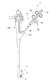
- FIG. 1 is an overall view showing a suturing device according to an embodiment of the present invention.
- the suturing device 1 is an apparatus that is used together with an endoscope 100 and sutures a living tissue using a suture thread 6.
- the suturing device 1 includes a suturing needle 2 to which a suture thread 6 is attached and an applicator 10 for puncturing the suturing needle 2 into a living tissue.
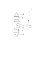
- FIG. 2 is a schematic diagram showing a suture needle.
- the suture needle 2 is a needle having one end (first end) formed in a cone shape and the other end (second end) formed sharply.
- the end part (first end part) 3 (second end part) 4 of the suture needle 2 is formed conically and sharply. That is, the end portions 3 and 4 of the suture needle 2 can puncture a living tissue.
- two groove portions 5 that are engaged with a pair of needle fixing portions 30 described later are formed between the end portions 3 and 4 of the suture needle 2, two groove portions 5 that are engaged with a pair of needle fixing portions 30 described later are formed.
- Each groove 5 has an outer diameter smaller than the maximum outer diameter of the conical portion at the end of the suture needle 2.
- an end portion of the suture thread 6 is fixed between the groove portions 5 in the intermediate portion of the suture needle 2.
- the applicator 10 includes a treatment section 11, a long shaft member 50 in which the treatment section 11 is arranged at one end (first end), and the other end (second end) of the long shaft member 50.
- the operation unit 60 is provided.
- the side on which the treatment unit 11 is disposed will be described as the distal end side
- the side on which the operation unit 60 is disposed will be described as the proximal end side.
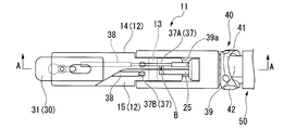
- FIG. 3A is a plan view showing the treatment portion 11 in the suture instrument 1.
- FIG. 3B is a plan view showing a partial configuration of the treatment section 11.
- FIG. 3C is a view for explaining the operation of the treatment portion 11 in the suture instrument 1.
- 4A is a cross-sectional view taken along line AA in FIG. 3A.
- 4B is a cross-sectional view showing a state in which the suture needle 2 and the needle fixing portion 30 are removed in FIG. 4A.
- the treatment section 11 includes a pair of gripping members 12, a pair of needle fixing sections 30 provided on the pair of gripping members 12, and a pair of gripping members 12 as long axes.
- the cover member 39 connected to the member 50 and the link member 40 connected to the long shaft member 50 are provided.
- the pair of gripping members 12 includes a first gripping member 14 and a second gripping member 15 that are connected to each other by a pin 13 at a proximal end portion so as to be relatively rotatable.
- the first gripping member 14 and the second gripping member 15 are relatively rotated with the central axis of the pin 13 as the center of rotation. Thereby, a pair of holding member 12 opens and closes.
- the first gripping member 14 is formed with a first gripping surface 17 for gripping the living tissue
- the second gripping member 15 is formed with a second gripping surface 18 for gripping the living tissue.
- a recess 19 is formed in the first gripping surface 17 so as to be recessed in a direction perpendicular to the first gripping surface 17.
- a recess 20 is formed in the second gripping surface 18 so as to be recessed in a direction orthogonal to the second gripping surface 18.
- the depressions 19 and 20 formed in the first gripping surface 17 and the second gripping surface 18 have shapes that follow the shapes of the end portions 3 and 4 of the suture needle 2.
- the end portions 3 and 4 of the suture needle 2 are fitted in the recesses 19 and 20.
- a link 25 is connected to the base ends of the pair of gripping members 12. Further, an opening / closing wire 26 (power transmission member) is fixed to the link 25.
- the link 25 is provided to convert the advance / retreat operation of the opening / closing wire 26 into the opening / closing operation of the pair of gripping members 12.
- the open / close wire 26 has a distal end connected to the pair of gripping members 12 via the link 25, and a proximal end connected to the operation unit 60 (see FIG. 1).
- the opening / closing wire 26 is a wire rod (for example, a stranded wire) fixed to the proximal end of the link 25, and is inserted through the coil sheath 52 (see FIG. 7) inside the long shaft member 50.
- the pair of needle fixing portions 30 are arranged inside each of the pair of gripping members 12.
- the pair of gripping members 12 are provided with grooves 21 and 22 into which the needle fixing portion 30 is inserted, and lids 23 and 24 that respectively close the grooves 21 and 22.
- the grooves 21 and 22 are formed so as to extend from the distal ends of the pair of gripping members 12 toward the proximal end, and the distal ends of the grooves 21 and 22 are opened.
- a needle fixing first member 31 which is a plate-like member constituting the pair of needle fixing portions 30, is inserted into the groove 21.
- the needle fixing first member 31 is formed with a through hole 33 penetrating in the plate thickness direction and a locking hole portion 35 formed so as to be connected to the through hole 33.
- the through hole 33 has an inner diameter that is substantially the same as the inner diameter of the recess 19 (see FIGS. 4A and 4B) formed in the pair of gripping members 12.
- One of the end portions 3 and 4 of the suture needle 2 can be inserted into the through-hole 33.
- the width of the locking hole portion 35 is smaller than the inner diameter of the through hole 33 and larger than the outer diameter of the groove portion 5 formed in the suture needle 2. Further, the locking hole portion 35 is disposed on the proximal end side of the through hole 33. Thereby, when the locking hole 35 enters the groove 5 of the suture needle 2, one of the end portions 3 and 4 of the suture needle 2 is fixed to the needle fixing first member 31.
- a needle fixing second member 32 which is a plate-like member constituting the pair of needle fixing portions 30, is inserted into the groove 22.
- the needle fixing second member 32 is formed with a through hole 34 similar to the above-described through hole 33 and a locking hole portion 36 similar to the above-described locking hole portion 35.
- the needle fixing second member 32 is formed in the same shape and size as the needle fixing first member 31. The shape of the needle fixing second member 32 and the needle fixing first member 31 may be different from each other.
- a delivery wire 37 (linear member) is fixed to the proximal ends of the pair of needle fixing portions 30. That is, the distal end of the first delivery wire 37 ⁇ / b> A (first linear member) is fixed to the proximal end of the needle fixing first member 31, and the delivery first wire 37 ⁇ / b> A (first linear member) is attached to the proximal end of the needle fixing second member 32. The tip of the two wires 37B (second linear member) is fixed. The delivery wire 37 is disposed at a position separated from the link 25 so as to avoid the link 25.
- the delivery wire 37 In the delivery wire 37, a range from the pin 13 that is an opening and closing shaft of the pair of gripping members 12 to the tip of the delivery wire 37 is covered with a hard pipe 38.
- the delivery wire 37 has flexibility in a portion B (see FIGS. 3A, 3B, and 3C) that is curved by opening and closing operations of the pair of gripping members 12 (see FIG. 3A), and the curved portion B is bent.
- it has high rigidity that is less likely to buckle on the tip side.
- the pipe 38 that covers the delivery wire 37 may be made of a material harder than the delivery wire 37 or may be a pipe having the same hardness as the delivery wire 37. That is, the pipe 38 that covers the delivery wire 37 only needs to reinforce the delivery wire 37.
- the cover member 39 is a cylindrical member fixed to the tip of the long shaft member 50.
- the cover member 39 holds both ends of the pin 13.
- a link 25 and an opening / closing wire 26 for opening and closing the pair of gripping members 12 are inserted inside the cover member 39.
- a slit 39 a is formed on the outer peripheral surface of the cover member 39 to prevent the pair of gripping members 12 and the link 25 from interfering with the cover member 39 when the pair of gripping members 12 are opened and closed.
- FIG. 5 is a perspective view showing the link member 40.
- the link member 40 includes an annular main body 41, rotation support portions 42 and 43, and a pair of connection portions 44 and 45.
- the main body 41 rotates relative to the cover member 39 with the central axis of the rotation support portions 42 and 43 as the rotation center.
- An opening / closing wire 26 and a delivery wire 37 are inserted inside the annular body 41.
- the rotation support portions 42 and 43 are formed in a columnar shape having a central axis extending in a direction intersecting the longitudinal axis of the long shaft member 50.
- the shape of the rotation support parts 42 and 43 is not limited to a cylindrical shape, and may be other than a cylindrical shape.
- the rotation support portions 42 and 43 are provided for the purpose of connecting the main body 41 to the cover member 39.
- the rotation support portions 42 and 43 have the center axis X directed in a direction orthogonal to the longitudinal axis of the long shaft member 50.
- the rotation support parts 42 and 43 are arrange
- the rotation support portions 42 and 43 are fixed to the main body 41. Furthermore, the ends 42a and 43a facing the inside of the main body 41 in the rotation support portions 42 and 43 are inserted into the cover member 39 (see FIG. 3A). Accordingly, as shown in FIG. 3A, the main body 41 is connected to the cover member 39 by the rotation support portions 42 and 43. That is, in the present embodiment, the rotation support portions 42 and 43 connect the link member 40 and the long shaft member 50 via the cover member 39.
- the connecting portions 44 and 45 are two rod-like members extending in parallel with each other, and the delivery wire 37 is inserted through the main body 41.
- the rod-shaped members constituting the connecting portions 44 and 45 are rotatable relative to the main body 41 with the central axes X ′ and X ′′ as the rotation centers.
- each rod-shaped member At the center in the central axis direction of each rod-shaped member, holes 44a and 45a extending in the direction perpendicular to the central axis are formed.
- Two delivery wires 37 (a delivery first wire 37A and a delivery second wire 37B) are respectively inserted into the holes 44a and 45a formed in the respective rod-shaped members constituting the connecting portions 44 and 45. .
- the connecting portions 44 and 45 can connect the delivery wire 37 to the longitudinal axis of the long shaft member 50 regardless of the rotating angle of the main body 41 itself. Maintain approximately parallel to the axis.
- the connecting portions 44 and 45 do not have to be rod-like members, and the same effect can be obtained as long as the connecting portions 44 and 45 are rotatable relative to the main body 41.
- a cylindrical member 46 is fixed to the delivery wire 37 ⁇ / b> A inserted through the holes 44 a and 45 a of the coupling portions 44 and 45.
- the delivery second wire 37 ⁇ / b> B is also provided with the same configuration as the cylindrical member 46.
- a delivery wire 37 is inserted into the cylindrical member 46. Further, the cylindrical member 46 abuts on the opening end of the hole 44 a formed in the connecting portion 44. The delivery wire 37 is positioned with respect to the connecting portion 44 by the cylindrical member 46 coming into contact with the opening end of the connecting portion 44. The cylindrical member 46 a disposed on the distal end side of the connecting portion 44 in the cylindrical member 46 is attached to the delivery wire 37 by a fixing method having a strength capable of withstanding the traction force when the delivery wire 37 is pulled to the proximal end side. It is fixed.
- cylindrical member 46b disposed on the proximal end side of the connecting portion 44 in the cylindrical member 46 has a strength that can withstand the pressing force when the delivery wire 37 is pressed to the distal end side by the connecting portion 44. It is fixed to the delivery wire 37 by a method.
- the frictional resistance generated in the transfer wire 37 on the proximal side from the link member 40 is larger than the frictional resistance generated in the transfer wire 37 on the distal side from the link member 40.
- the cylindrical member 46a disposed on the distal end side of the connecting portions 44 and 45 has a fixing method having higher strength than the cylindrical member 46b disposed on the proximal end side of the connecting portions 44 and 45. It has been adopted.
- the cylindrical member 46 a disposed on the distal end side of the connecting portions 44 and 45 is fixed to the delivery wire 37 by laser welding.
- the cylindrical member 46 b disposed on the base end side of the connecting portions 44 and 45 is fixed to the delivery wire 37 by brazing or the like. Note that the fixing method of each cylindrical member 46 to the delivery wire 37 may be a different fixing method in consideration of workability.
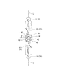
- FIG. 6 is a front view of the treatment section.
- the link member 40 in order to emphasize the positional relationship of the link member 40, the link member 40 hidden behind the pair of gripping members 12, the cover member 39, etc. is intentionally shown.
- the link member 40 has a positional relationship in which the entire link member 40 is displaced in the circumferential direction with respect to the midline L of the pair of gripping members 12.
- the transfer wire 37 is parallel to the longitudinal axis of the long shaft member 50 in the region from the pair of gripping members 12 to the holes 44a and 45a of the connecting portions 44 and 45. It becomes a straight line state.
- FIG. 7 is a cross-sectional view showing a cross section perpendicular to the longitudinal axis of the long shaft member.
- the long shaft member 50 includes a resin outer sheath 51 and a coil sheath 52 inserted through the outer sheath 51.
- the outer sheath 51 and the coil sheath 52 constituting the long axis member 50 are flexible members having a longitudinal axis.
- the outer sheath 51 is a cylindrical member having an outer diameter that can be inserted into a treatment instrument channel (indicated by reference numeral 101 in FIG. 1) of an endoscope.
- the outer surface of the outer sheath 51 is a surface state with low frictional resistance against the inner surface of the treatment instrument channel 101.
- the coil sheath 52 is a sheath in which a wire is wound in a coil shape with the longitudinal axis of the long shaft member 50 as the center, and is a sheath that balances flexibility and resistance to compression in the longitudinal axis direction.
- An opening / closing wire 26 is inserted into the coil sheath 52.
- the outer sheath 51 and the coil sheath 52 are in a state where their centerlines are shifted in parallel.
- second coil sheaths 53 and 54 are disposed between the outer sheath 51 and the coil sheath 52.
- the second coil sheaths 53 and 54 are cylindrical members through which the delivery wire 37 is inserted.
- the second coil sheaths 53 and 54 are disposed adjacent to each other inside the long shaft member 50. Accordingly, the maximum outer diameter of the bundle of the coil sheath 52 and the second coil sheaths 53 and 54 is reduced as compared with the case where the second coil sheaths 53 and 54 are arranged at positions facing the radial direction of the coil sheath 52. Can do.
- the thickness d2 of the outer sheath 51a in the case where the second coil sheaths 53 and 54 are arranged at positions facing each other with the coil sheath 52 interposed therebetween is shown in FIG.
- the thickness d1 of the outer sheath 51 can be increased without increasing the outer diameter of the outer sheath 51. For this reason, it is possible to achieve both reduction in the diameter of the long shaft member 50 and prevention of buckling of the long shaft member 50.
- the opening ends on the distal end side of the second coil sheaths 53 and 54 are arranged at positions spaced from the link member 40 toward the proximal end side.
- the transfer wire 37 extending from the opening end on the distal end side of the second coil sheaths 53 and 54 is passed to the holes 44a and 45a formed in the connecting portions 44 and 45 provided in the link member 40 (see FIGS. 4A and 4B). Each of them extends.
- the operation unit 60 includes a first slider 61 for pushing and pulling the opening / closing wire 26, and second sliders 62 and 63 for pulling each of the delivery wires 37.
- the base end of the opening / closing wire 26 is fixed to the first slider 61.
- the second slider 62 is a slider for pulling the delivery first wire 37A.
- the second slider 63 is a slider for pulling the delivery second wire 37B.
- the base ends of the transfer wires 37 are fixed to the second sliders 62 and 63.
- the operation unit 60 is an open / close operation unit that performs an operation of transmitting power to the open / close wire 26 in order to open / close the pair of gripping members 12, and the transfer wire 37 is connected to the long shaft member 50.
- This is a needle fixing operation unit that performs an operation of moving the needle 2 along the longitudinal axis of the needle 2 to fix and release the suture needle 2 from the needle fixing unit 30.
- the configuration of the operation unit 60 is not limited to the configuration having the first slider 61 and the second sliders 62 and 63.
- the operation unit 60 employs a configuration in which the opening / closing wire 26 or the delivery wire 37 is moved using a lever, a configuration in which the opening / closing wire 26 or the delivery wire 37 is wound around a rotating shaft, and the like. It may be.
- FIG. 9 and FIG. 10 are explanatory views showing one process when the suturing device 1 is used.
- FIG. 11 is a schematic diagram for explaining the operation of the suturing device 1.
- the suturing device 1 is prepared in a state where the suturing needle 2 is attached to one of the pair of gripping members 12 provided in the suturing device 1 (second gripping member 15 in FIG. 9).
- the suturing device 1 is inserted into the treatment instrument channel 101 of the endoscope 100 from the treatment unit 11 side and guided to a target site that is a target for suturing a living tissue.
- the first slider 61 shown in FIG. 1 is pulled to close the pair of gripping members 12 to the site T to be sutured as shown in FIG. Grasp the living tissue located.
- the suturing needle 2 attached to one of the pair of gripping members 12 is the gripping surface of the other of the pair of gripping members 12 (first gripping member 14) ( It enters into the depression (indentation 19) formed in the first gripping surface 17).
- the suture needle 2 is punctured into the living tissue Ta between the gripping surfaces 17 and 18 arranged to face each other in the pair of gripping members 12.
- the suturing device 1 of the present embodiment when the traction force of the first slider 61 shown in FIG. 1 is loosened, the grasping of the living tissue between the first grasping surface 17 and the second grasping surface 18 is released.
- the first slider 61 is moved to the tip side, the pair of gripping members 12 are opened.
- the suture needle 2 remains attached to the second gripping member 15.
- the suture needle 2 can be re-stabbed into the living tissue.
- the living tissue is moved in the same manner as a grasping forceps that merely grasps the living tissue. Or change the direction of the living tissue.
- the connecting portion 45 of the link member 40 is moved to the proximal end side on the distal end side of the long shaft member 50. Since the link member 40 can be rotated with respect to the cover member 39 by the rotation support portions 42 and 43, when the connecting portion 45 is moved to the proximal end side, the connecting portion 44 is moved to the distal end side.
- the first wire for transfer 37A the portion on the distal end side with respect to the link member 40 is pressed toward the distal end side
- the first wire for transfer 37A the portion on the proximal end side with respect to the link member 40 is pulled toward the distal end side. . That is, the delivery first wire 37 ⁇ / b> A moves to the distal end side as a whole by the action of the link member 40.
- the needle fixing first member 31 to which the distal end of the delivery first wire 37A is secured is pressed by the delivery first wire 37A and moves to the distal end side. Then, the needle fixing first member 31 moves so that the locking hole portion 35 enters the groove portion 5. As a result, the suture needle 2 is fixed to the needle fixing first member 31.
- the needle fixing second member 32 to which the distal end of the delivery second wire 37B is secured moves to the proximal end side when the delivery second wire 37B is pulled. Then, the needle fixing second member 32 moves so that the locking hole portion 36 is disengaged from the groove portion 5. Thereby, the suture needle 2 can be detached from the needle fixing second member 32.
- the first wire for delivery 37A is positioned closer to the first gripping member 14 than the pin 13, and the second wire for delivery 37B is closer to the first than the pin 13. It is located on the two gripping member 15 side. Accordingly, when the pair of gripping members 12 is opened, the pair of needle fixing portions 30 is pressed so that the pair of needle fixing portions 30 are relatively advanced with respect to the pair of gripping members 12. As a result, the locking hole portion of the needle fixing first member 31 or the needle fixing second member 32 enters the groove portion 5 formed in the suturing needle 2, and the suturing needle 2 is moved by a slight forward and backward movement of the second sliders 62 and 63. Do not fall off.
- the suture thread 6 is ligated as necessary, and a series of treatments is completed.
- the suture thread 6 may be inserted through the living tissue again.
- the pair of gripping members 12 are closed, and the delivery second wire 37 ⁇ / b> B is moved to the proximal end side in the operation unit 60.
- the suture needle 2 can be detached from the needle fixing second member 32 provided on the second gripping member 15, and at the same time, the suture needle 2 can be removed by the needle fixing first member 31 provided on the first gripping member 14. It is fixed to one gripping member 14.
- the suturing device 1 can grasp a tissue to sew a living tissue and deliver the suturing needle 2 between a pair of grasping members 12, and can also hold the suturing needle 2 after grasping the living tissue once.
- the gripping member 12 can be opened again without delivery.
- grips a biological tissue and the function as an apparatus which sutures a biological tissue can be reconciled.
- the suturing device 1 can be used by inserting the suturing device 1 into the treatment instrument channel of the flexible endoscope, it is necessary to suture the living tissue when performing a diagnosis using the flexible endoscope. When a special site is found, the treatment tool of the suture instrument 1 can be easily guided to the suture target site.
- an endoscope provided with only one treatment instrument channel, it is possible to move a living tissue in the vicinity of a suture target site or suture a suture target site without separately preparing a grasping forceps. .
- the suturing position can be easily changed after once grasping the living tissue.
- the above embodiment can be suitably applied to a suturing device that sutures biological tissue.
Abstract
La présente invention concerne un dispositif de suture qui est doté : d'un élément axe long ; d'une paire d'éléments de préhension ; d'une aiguille de suture ; d'un élément de transmission de puissance ; d'un élément d'actionnement d'ouverture/de fermeture ; d'une paire de sections de fixation d'aiguille ayant un premier élément de fixation d'aiguille et un second élément de fixation d'aiguille et fixant ou libérant l'aiguille de suture à ou de la paire d'éléments de préhension ; d'une paire d'éléments linéaires raccordés à la paire de sections de fixation d'aiguille ; d'une section d'actionnement de fixation d'aiguille pour actionner la paire d'éléments linéaires ; d'un élément de liaison ayant une première extrémité et une seconde extrémité, qui sont raccordées à la paire d'éléments linéaires ; et des sections de support rotatives pour supporter de manière rotative l'élément de liaison.
Priority Applications (4)
| Application Number | Priority Date | Filing Date | Title |
|---|---|---|---|
| CN201380044189.8A CN104582590B (zh) | 2012-08-24 | 2013-08-07 | 缝合器 |
| EP13831750.8A EP2889008B1 (fr) | 2012-08-24 | 2013-08-07 | Dispositif de suture |
| JP2014510600A JPWO2014030544A1 (ja) | 2012-08-24 | 2013-08-07 | 縫合器 |
| US14/627,289 US9901336B2 (en) | 2012-08-24 | 2015-02-20 | Suture device |
Applications Claiming Priority (2)
| Application Number | Priority Date | Filing Date | Title |
|---|---|---|---|
| US201261693028P | 2012-08-24 | 2012-08-24 | |
| US61/693,028 | 2012-08-24 |
Related Child Applications (1)
| Application Number | Title | Priority Date | Filing Date |
|---|---|---|---|
| US14/627,289 Continuation US9901336B2 (en) | 2012-08-24 | 2015-02-20 | Suture device |
Publications (1)
| Publication Number | Publication Date |
|---|---|
| WO2014030544A1 true WO2014030544A1 (fr) | 2014-02-27 |
Family
ID=50149853
Family Applications (1)
| Application Number | Title | Priority Date | Filing Date |
|---|---|---|---|
| PCT/JP2013/071408 WO2014030544A1 (fr) | 2012-08-24 | 2013-08-07 | Dispositif de suture |
Country Status (5)
| Country | Link |
|---|---|
| US (1) | US9901336B2 (fr) |
| EP (1) | EP2889008B1 (fr) |
| JP (2) | JPWO2014030544A1 (fr) |
| CN (1) | CN104582590B (fr) |
| WO (1) | WO2014030544A1 (fr) |
Cited By (6)
| Publication number | Priority date | Publication date | Assignee | Title |
|---|---|---|---|---|
| WO2016051821A1 (fr) * | 2014-09-29 | 2016-04-07 | オリンパス株式会社 | Dispositif de suture |
| WO2016074331A1 (fr) * | 2014-11-14 | 2016-05-19 | 江苏江科知识产权运营有限公司 | Instrument chirurgical mini-invasif pour nouer et procédé associé permettant de nouer et de couper |
| WO2017018001A1 (fr) * | 2015-07-29 | 2017-02-02 | オリンパス株式会社 | Instrument pour suture |
| CN107427295A (zh) * | 2015-03-18 | 2017-12-01 | 奥林巴斯株式会社 | 缝合器 |
| JP2021521977A (ja) * | 2018-04-25 | 2021-08-30 | メロン メディカル ビー ブイ | 針‐縫合糸結合体、針ホルダー及び手術用縫合装置 |
| US11806007B2 (en) | 2018-05-25 | 2023-11-07 | Suturion Ab | Suturing device |
Families Citing this family (6)
| Publication number | Priority date | Publication date | Assignee | Title |
|---|---|---|---|---|
| WO2017018002A1 (fr) * | 2015-07-29 | 2017-02-02 | オリンパス株式会社 | Instrument pour suture |
| WO2017022326A1 (fr) * | 2015-08-04 | 2017-02-09 | オリンパス株式会社 | Dispositif de suture |
| US10271836B2 (en) * | 2015-12-01 | 2019-04-30 | Covidien Lp | Powered endoscopic suturing device |
| CN109984777B (zh) * | 2017-12-29 | 2022-02-08 | 江苏木偶医疗科技有限公司 | 一种驱动结构及具有柔性关节的装置 |
| DE112018007329T5 (de) * | 2018-03-22 | 2020-12-03 | Olympus Corporation | Nadelhalter und Verfahren zu dessen Verwendung |
| CN113069159B (zh) * | 2021-03-26 | 2023-03-03 | 象山县第一人民医院医疗健康集团 | 一种肺部手术用缝合器 |
Citations (4)
| Publication number | Priority date | Publication date | Assignee | Title |
|---|---|---|---|---|
| JPH07155332A (ja) * | 1993-10-08 | 1995-06-20 | United States Surgical Corp | 装填機構を備えた手術用縫合装置 |
| JP2001500765A (ja) | 1996-09-23 | 2001-01-23 | シンバイオシス コーポレイション | 自動針受渡し縫合器 |
| JP2010005386A (ja) * | 2008-06-13 | 2010-01-14 | Tyco Healthcare Group Lp | 内視鏡的ステッチング装置 |
| JP2010505519A (ja) * | 2006-10-05 | 2010-02-25 | タイコ ヘルスケア グループ リミテッド パートナーシップ | 可撓性の内視鏡的縫合装置 |
Family Cites Families (5)
| Publication number | Priority date | Publication date | Assignee | Title |
|---|---|---|---|---|
| US5478344A (en) * | 1993-10-08 | 1995-12-26 | United States Surgical Corporation | Surgical suturing apparatus with loading mechanism |
| US8864776B2 (en) * | 2008-04-11 | 2014-10-21 | Covidien Lp | Deployment system for surgical suture |
| US20110040308A1 (en) * | 2008-06-13 | 2011-02-17 | Ramiro Cabrera | Endoscopic Stitching Devices |
| US8968339B2 (en) * | 2010-12-10 | 2015-03-03 | Covidien Lp | Suturing device with deployable needle |
| US8968340B2 (en) * | 2011-02-23 | 2015-03-03 | Covidien Lp | Single actuating jaw flexible endolumenal stitching device |
-
2013
- 2013-08-07 WO PCT/JP2013/071408 patent/WO2014030544A1/fr active Application Filing
- 2013-08-07 EP EP13831750.8A patent/EP2889008B1/fr active Active
- 2013-08-07 JP JP2014510600A patent/JPWO2014030544A1/ja active Pending
- 2013-08-07 CN CN201380044189.8A patent/CN104582590B/zh active Active
-
2014
- 2014-12-16 JP JP2014254412A patent/JP5815109B2/ja active Active
-
2015
- 2015-02-20 US US14/627,289 patent/US9901336B2/en active Active
Patent Citations (4)
| Publication number | Priority date | Publication date | Assignee | Title |
|---|---|---|---|---|
| JPH07155332A (ja) * | 1993-10-08 | 1995-06-20 | United States Surgical Corp | 装填機構を備えた手術用縫合装置 |
| JP2001500765A (ja) | 1996-09-23 | 2001-01-23 | シンバイオシス コーポレイション | 自動針受渡し縫合器 |
| JP2010505519A (ja) * | 2006-10-05 | 2010-02-25 | タイコ ヘルスケア グループ リミテッド パートナーシップ | 可撓性の内視鏡的縫合装置 |
| JP2010005386A (ja) * | 2008-06-13 | 2010-01-14 | Tyco Healthcare Group Lp | 内視鏡的ステッチング装置 |
Cited By (15)
| Publication number | Priority date | Publication date | Assignee | Title |
|---|---|---|---|---|
| CN106714703A (zh) * | 2014-09-29 | 2017-05-24 | 奥林巴斯株式会社 | 缝合器 |
| WO2016051821A1 (fr) * | 2014-09-29 | 2016-04-07 | オリンパス株式会社 | Dispositif de suture |
| JP6081665B2 (ja) * | 2014-09-29 | 2017-02-15 | オリンパス株式会社 | 縫合器 |
| WO2016074331A1 (fr) * | 2014-11-14 | 2016-05-19 | 江苏江科知识产权运营有限公司 | Instrument chirurgical mini-invasif pour nouer et procédé associé permettant de nouer et de couper |
| EP3272296A4 (fr) * | 2015-03-18 | 2019-01-16 | Olympus Corporation | Dispositif de suture |
| CN107427295A (zh) * | 2015-03-18 | 2017-12-01 | 奥林巴斯株式会社 | 缝合器 |
| US10357244B2 (en) | 2015-03-18 | 2019-07-23 | Olympus Corporation | Suturing device |
| JP6165403B2 (ja) * | 2015-07-29 | 2017-07-19 | オリンパス株式会社 | 縫合器 |
| JPWO2017018001A1 (ja) * | 2015-07-29 | 2017-09-07 | オリンパス株式会社 | 縫合器 |
| US20180140294A1 (en) * | 2015-07-29 | 2018-05-24 | Olympus Corporation | Suture device |
| WO2017018001A1 (fr) * | 2015-07-29 | 2017-02-02 | オリンパス株式会社 | Instrument pour suture |
| US10729425B2 (en) | 2015-07-29 | 2020-08-04 | Olympus Corporation | Suture device |
| JP2021521977A (ja) * | 2018-04-25 | 2021-08-30 | メロン メディカル ビー ブイ | 針‐縫合糸結合体、針ホルダー及び手術用縫合装置 |
| JP7386181B2 (ja) | 2018-04-25 | 2023-11-24 | メロン メディカル ビー ブイ | 針‐縫合糸結合体、針ホルダー及び手術用縫合装置 |
| US11806007B2 (en) | 2018-05-25 | 2023-11-07 | Suturion Ab | Suturing device |
Also Published As
| Publication number | Publication date |
|---|---|
| JP5815109B2 (ja) | 2015-11-17 |
| JPWO2014030544A1 (ja) | 2016-07-28 |
| CN104582590B (zh) | 2017-02-22 |
| US9901336B2 (en) | 2018-02-27 |
| EP2889008A1 (fr) | 2015-07-01 |
| JP2015061669A (ja) | 2015-04-02 |
| EP2889008A4 (fr) | 2016-05-18 |
| US20150230790A1 (en) | 2015-08-20 |
| CN104582590A (zh) | 2015-04-29 |
| EP2889008B1 (fr) | 2018-06-20 |
Similar Documents
| Publication | Publication Date | Title |
|---|---|---|
| JP5815109B2 (ja) | 縫合器 | |
| US11779326B2 (en) | Stitching device with long needle | |
| US10595856B2 (en) | Stitching device with long needle delivery | |
| JP2010274128A (ja) | 内視鏡用処置具 | |
| US9693769B2 (en) | Suture device | |
| WO2013161764A1 (fr) | Élément de manœuvre | |
| JP6184639B2 (ja) | 縫合器 | |
| WO2016002932A1 (fr) | Porte-aiguille de suture et système d'endoscope | |
| US20240057998A1 (en) | Magnet-assisted suture grasper comprising a suture retrieval needle, a retriever body, a grasper wire, a grasper arm, and a grasper magnet | |
| US20130172913A1 (en) | Suture thread pushing apparatus and suture thread pushing system | |
| WO2013005752A1 (fr) | Dispositif de fixation de tissu | |
| WO2018229925A1 (fr) | Cathéter | |
| JP6180694B2 (ja) | 縫合装置 | |
| JPWO2017110287A1 (ja) | 内視鏡用鉗子および内視鏡用鉗子の製造方法 | |
| EP3520717B1 (fr) | Dispositif de retrait de clip | |
| WO2020079824A1 (fr) | Outil de traitement d'endoscope | |
| WO2014061505A1 (fr) | Outil de traitement pour endoscope | |
| WO2021176636A1 (fr) | Porte-aiguille pour endoscope, et procédé de suture endoscopique | |
| JPWO2019163086A1 (ja) | 内視鏡用処置具および内視鏡システム | |
| WO2022079788A1 (fr) | Instrument de traction, système de traction, procédé de traction de fil de suture, et procédé de suture | |
| US11369367B2 (en) | Suturing device | |
| EP3332716B1 (fr) | Instrument pour suture | |
| WO2021183511A1 (fr) | Procédés d'accouplement d'éléments de dispositif et dispositifs associés comportant de tels éléments | |
| JP2018068410A (ja) | 処置具 |
Legal Events
| Date | Code | Title | Description |
|---|---|---|---|
| ENP | Entry into the national phase |
Ref document number: 2014510600 Country of ref document: JP Kind code of ref document: A |
|
| 121 | Ep: the epo has been informed by wipo that ep was designated in this application |
Ref document number: 13831750 Country of ref document: EP Kind code of ref document: A1 |
|
| NENP | Non-entry into the national phase |
Ref country code: DE |
|
| WWE | Wipo information: entry into national phase |
Ref document number: 2013831750 Country of ref document: EP |