WO2014027378A1 - 体内水分計 - Google Patents
体内水分計 Download PDFInfo
- Publication number
- WO2014027378A1 WO2014027378A1 PCT/JP2012/005153 JP2012005153W WO2014027378A1 WO 2014027378 A1 WO2014027378 A1 WO 2014027378A1 JP 2012005153 W JP2012005153 W JP 2012005153W WO 2014027378 A1 WO2014027378 A1 WO 2014027378A1
- Authority
- WO
- WIPO (PCT)
- Prior art keywords
- insertion portion
- side insertion
- distal
- end side
- moisture meter
- Prior art date
- Legal status (The legal status is an assumption and is not a legal conclusion. Google has not performed a legal analysis and makes no representation as to the accuracy of the status listed.)
- Ceased
Links
Images





Classifications
-
- A—HUMAN NECESSITIES
- A61—MEDICAL OR VETERINARY SCIENCE; HYGIENE
- A61B—DIAGNOSIS; SURGERY; IDENTIFICATION
- A61B5/00—Measuring for diagnostic purposes; Identification of persons
- A61B5/05—Detecting, measuring or recording for diagnosis by means of electric currents or magnetic fields; Measuring using microwaves or radio waves
- A61B5/053—Measuring electrical impedance or conductance of a portion of the body
- A61B5/0538—Measuring electrical impedance or conductance of a portion of the body invasively, e.g. using a catheter
-
- A—HUMAN NECESSITIES
- A61—MEDICAL OR VETERINARY SCIENCE; HYGIENE
- A61B—DIAGNOSIS; SURGERY; IDENTIFICATION
- A61B5/00—Measuring for diagnostic purposes; Identification of persons
- A61B5/05—Detecting, measuring or recording for diagnosis by means of electric currents or magnetic fields; Measuring using microwaves or radio waves
- A61B5/053—Measuring electrical impedance or conductance of a portion of the body
- A61B5/0537—Measuring body composition by impedance, e.g. tissue hydration or fat content
-
- A—HUMAN NECESSITIES
- A61—MEDICAL OR VETERINARY SCIENCE; HYGIENE
- A61B—DIAGNOSIS; SURGERY; IDENTIFICATION
- A61B2560/00—Constructional details of operational features of apparatus; Accessories for medical measuring apparatus
- A61B2560/04—Constructional details of apparatus
- A61B2560/0406—Constructional details of apparatus specially shaped apparatus housings
- A61B2560/0418—Pen-shaped housings
-
- A—HUMAN NECESSITIES
- A61—MEDICAL OR VETERINARY SCIENCE; HYGIENE
- A61B—DIAGNOSIS; SURGERY; IDENTIFICATION
- A61B2562/00—Details of sensors; Constructional details of sensor housings or probes; Accessories for sensors
- A61B2562/24—Hygienic packaging for medical sensors; Maintaining apparatus for sensor hygiene
- A61B2562/247—Hygienic covers, i.e. for covering the sensor or apparatus during use
Definitions
- the present invention relates to an in-vivo moisture meter that measures the amount of moisture in the living body of a subject.
- Dehydration in the living body is a pathological condition in which water in the living body decreases, and it is often expressed during exercise when high water is discharged from the body due to sweating or body temperature rise or when the temperature is high.
- the water retention ability of the living body itself is reduced, and thus dehydration is more likely to occur than in a normal healthy person.
- body temperature regulation is impaired when water in the body loses 3% or more of body weight.
- body temperature regulation disorder occurs and the body temperature rises, it causes a further decrease in water in the living body and falls into a vicious circle, eventually leading to a disease state called heat stroke.
- Heat stroke has pathological conditions such as heat convulsions, heat fatigue, and heat stroke, and sometimes systemic organ damage may occur. For this reason, it is important to accurately grasp the amount of water in the living body in order to avoid the risk of heat stroke.
- the applicant of the present application pays attention to the subject's axilla as a part suitable for accurately grasping the amount of water in the living body, and assigns a sensor unit in which electrodes are arranged in the axilla.
- a sensor unit in which electrodes are arranged in the axilla.
- FIG. 8 is a diagram showing an example of the moisture meter 800 in the body proposed by the applicant of the present application.
- the moisture meter 800 in a body is provided with the main-body part 810 and the insertion part 820, and the main-body part hold
- a display unit 812 is arranged on the housing surface of the main body unit 810, and a measurement result 831 and the like are displayed.
- the insertion portion 820 to be inserted into the axilla extends from one end of the main body portion 810 and is gently curved downward with respect to the main body portion 810 as a whole.
- the sensor portion 821 is slidably supported on the distal end surface 822 of the insertion portion 820.
- the sensor unit 821 has a sensor head 823 having a surface substantially parallel to the tip end surface 822, and in the direction of the arrow 841b in order to ensure a pressing force for ensuring the close contact of the sensor head 823 with the skin. It is energized. When the sensor head 823 is pressed against the skin of the subject's axilla, the sensor unit 821 slides by a predetermined amount in the direction of the arrow 841a, thereby starting measurement.
- the distal end surface 822 is provided with an opening for sliding the sensor portion 821 in the direction of the arrow 841a.
- 8b in FIG. 8 is a diagram showing a cross-sectional configuration of the distal end region 850 of the insertion portion 820 including the sensor portion 821.
- the opening 851 has a larger opening surface than the sensor head 823 of the sensor unit 821, and a gap 852 is provided between the side surface of the sensor unit 821 and the inner wall surface of the opening 851. Is secured. Thereby, the sensor part 821 can be slid smoothly.
- the present invention has been made in view of the above problems, and an object thereof is to improve waterproofness and antifouling properties in a moisture meter in a body in which a sensor unit is configured to be slidable.
- the moisture meter in the body has the following configuration. That is, A body moisture meter, A body portion formed in a straight line; An insertion portion that is curved and extended from one end of the main body, and The insertion part is A sensor unit that measures data on moisture in the living body by contacting the body surface of the subject, a distal-side insertion unit fixed to the distal end surface, A proximal-side insertion portion that supports the distal-side insertion portion via a slide mechanism that slides in a direction substantially orthogonal to the distal-end surface; A protective member that makes the slide mechanism between the distal end side insertion portion and the proximal end side insertion portion liquid-tight, A side wall portion that covers a part of the outer peripheral surface of the proximal end side insertion portion is formed on the proximal end side of the distal end side insertion portion, and the protection member is disposed inside the side wall portion. It is characterized by.
- the present invention it is possible to improve the waterproofness and antifouling property in the moisture meter in the body in which the sensor unit is configured to be slidable.
- FIG. 1A is a diagram showing an external configuration of a moisture meter in the body according to the first embodiment of the present invention.
- FIG. 1B is a diagram showing a configuration of a distal end region of the body moisture meter.
- FIG. 2 is a diagram showing a functional configuration of the moisture meter in the body.
- FIG. 3 is a diagram illustrating a configuration example of a measurement circuit of the moisture meter in the body.
- FIG. 4 is a diagram for explaining the operation of the moisture meter in the body.
- FIG. 5 is a diagram illustrating a data configuration of measurement information.
- FIG. 1A is a diagram showing an external configuration of a moisture meter in the body according to the first embodiment of the present invention.
- FIG. 1B is a diagram showing a configuration of a distal end region of the body moisture meter.
- FIG. 2 is a diagram showing a functional configuration of the moisture meter in the body.
- FIG. 3 is a diagram illustrating a configuration example of a
- FIG. 6 is a diagram showing an external configuration of the in-vivo moisture meter and a configuration of the tip region of the in-vivo moisture meter according to the second embodiment of the present invention.
- FIG. 7 is a diagram showing the external configuration of the moisture meter in the body according to the third embodiment of the present invention and the configuration of the tip region of the moisture meter in the body.
- FIG. 8 is a diagram showing the external configuration of the moisture meter in the body and the configuration of the tip region of the moisture meter in the body.
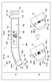
- FIG. 1A is a diagram showing an external configuration of an in-vivo moisture meter 100 according to the first embodiment of the present invention.
- the in-vivo moisture meter 100 brings the sensor part into contact with the skin of the axilla, which is the body surface of the subject, and detects the physical quantity according to the supplied electrical signal in the sensor part, thereby determining the moisture content in the subject's body. To detect.
- the body moisture meter 100 according to the present embodiment by measuring the subject's capacitance as the physical quantity (data on moisture in the living body), the wetness of the skin of the axilla is detected, and the moisture content in the body is determined. calculate.
- the in-vivo moisture meter 100 includes a main body 110 and an insertion section 120 that is curved and extended from one end of the main body 110.
- the main body 110 has an upper surface 114, a lower surface 115, and side surfaces 116 and 117 that are formed substantially parallel to the major axis direction (not shown), respectively, and are formed in a straight line as a whole.
- Various user interfaces are arranged on the surface of the casing of the main body 110, and an electronic circuit for calculating the amount of moisture in the body is housed inside the casing.
- a power switch 111 and a display unit 112 are shown as user interfaces.
- the power switch 111 is disposed in a recess in the rear end surface 113 of the main body 110.
- the power switch 111 is arranged in the recess in this way, an erroneous operation of the power switch 111 can be prevented.
- the power switch 111 When the power switch 111 is turned on, power supply from the power supply unit 211 (FIG. 2), which will be described later, to each part of the moisture meter 100 in the body is started, and the moisture meter 100 in the body enters an operating state.
- the display unit 112 is arranged on the side surface 117 of the main body unit 110 slightly forward in the long axis direction. This is because when the moisture content in the body of the subject is measured using the moisture meter 100 in the body, even if the measurer grips the grip region 118, the display unit 112 is completely displayed with the hand gripped by the measurer. In order to prevent the measurement result from being visually recognized even in a gripped state.
- the display unit 112 displays the current moisture content measurement result 131. For reference, the previous measurement result 132 is also displayed. Further, the battery display unit 133 displays the remaining amount of the battery (power supply unit 211 in FIG. 2). Further, when an invalid measurement result is obtained or a measurement error is detected, “E” is displayed on the display unit 112, and the measurement person is notified of this. Note that characters and the like displayed on the display unit 112 are displayed with the upper surface 114 side of the main body unit 110 as the upper side and the lower surface 115 side as the lower side.
- the upper portion 124 and the lower surface 125 of the insertion portion 120 of the moisture meter 100 in the body have a curved shape, and are gently curved downward as a whole with respect to the main body portion 110.
- the sensor unit 121 is fixed to the distal end surface 122 of the insertion unit 120.
- the sensor unit 121 includes a sensor head 123 having a surface substantially parallel to the distal end surface 122.
- the insertion section 120 is separated into a proximal insertion section 120-1 connected to the main body 110 and a distal insertion section 120-2 to which the sensor section 121 is fixed.
- -2 is urged in the direction of the arrow 141b by an elastic member such as a spring (for example, an urging force of about 150 gf) in order to ensure a pressing force for ensuring the close contact of the sensor head 123 with the skin.
- an elastic member such as a spring (for example, an urging force of about 150 gf) in order to ensure a pressing force for ensuring the close contact of the sensor head 123 with the skin.
- a predetermined amount for example, 1 mm to 10 mm, 3 mm in the present embodiment
- a slide direction the direction of the arrow 141a is referred to as a slide direction.
- the detailed configuration of the tip region (region indicated by the dotted line 161) of the moisture meter 100 in the body will be described later).
- the sensor head 123 when it is detected that the sensor head 123 is pressed against the axilla of the subject after the measurer turns on the power switch 111 to activate the moisture meter 100 in the body, The quantity measurement is started.
- the sensor head 123 applies a predetermined load (for example, 20 gf to 200 gf, more preferably 100 gf to 190 gf, more preferably) on the subject's axilla.
- a predetermined load for example, 20 gf to 200 gf, more preferably 100 gf to 190 gf, more preferably
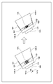
- FIG. 1B is a diagram showing the configuration of the distal end region of the moisture meter 100 in the body, and is a diagram showing the connection configuration between the distal insertion portion 120-2 and the proximal insertion portion 120-1. .
- the distal end side insertion portion 120-2 is provided with a side wall portion 181 so as to cover a part (front end side) of the outer peripheral surface of the distal end side insertion portion 120-2.
- the outer peripheral surface of the proximal end insertion portion 120-1 and the outer peripheral surface of the distal end insertion portion 120-2 are integrated. It is comprised so that it may become.
- the measurer is attached to the insertion portion 120.
- the wiping work when wiping off the dirt can be easily performed.
- a support member 171 is disposed on the proximal end side insertion portion 120-1, and slidably supports the distal end side insertion portion 120-2. Further, an elastic member 172 such as a spring is disposed to urge the distal end side insertion portion 120-2 in the direction of the arrow 141b. Note that a mechanism (sliding mechanism) for sliding the distal end side insertion portion 120-2 is covered with a protective member 151.
- the slide mechanism of the distal end side insertion portion 120-2 inside the protective member 151, it is possible to prevent liquid from entering the moisture meter 100 in the body through the slide mechanism. it can. That is, the waterproofness and antifouling property of the moisture meter 100 in the body can be improved.
- the protection member 151 can be expanded and contracted in the sliding direction, and the sensor head 123 is pressed against the skin of the axilla of the subject and pressed against the urging force of the elastic member 172, so that the distal end side insertion is performed.
- the protection member 151 contracts in the sliding direction (see the right side of the drawing).
- the protection member 151 can be expanded and contracted in the sliding direction, so that the sliding operation of the distal end side insertion portion 120-2 is not hindered by the protection member 151. It can be pressed with pressure.
- elastic members such as elastomers, such as silicone, a polyurethane, a styrene-type elastomer, polyolefin, such as polyethylene, are mentioned, for example.
- coating may be performed with a fluororesin having a trifluoromethyl group (—CF 3) as a functional group.
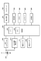
- FIG. 2 is a diagram illustrating a functional configuration of the moisture meter 100 in the body.
- the control unit 201 includes a CPU 202 and a memory 203, and the CPU 202 executes various programs in the body moisture meter 100 by executing a program stored in the memory 203.
- the CPU 202 performs display control of the display unit 112, which will be described later with reference to the flowchart of FIG. 4, drive control of the buzzer 222 and the LED lamp 223, measurement of moisture in the body (capacitance measurement in the present embodiment), and the like.
- the memory 203 includes a nonvolatile memory and a volatile memory.
- the nonvolatile memory is used as a program memory, and the volatile memory is used as a work memory for the CPU 202.
- the power supply unit 211 has a replaceable battery or a rechargeable battery, and supplies power to each part of the moisture meter 100 in the body.
- the voltage regulator 212 supplies a constant voltage (for example, 2.3 V) to the control unit 201 and the like.
- the battery remaining amount detection unit 213 detects the remaining amount of the battery based on the voltage value supplied from the power supply unit 211 and notifies the control unit 201 of the detection result.
- the control unit 201 controls the display of the battery display unit 133 based on the remaining battery level detection signal from the remaining battery level detection unit 213.
- the control unit 201 When the power switch 111 is pressed, power supply from the power supply unit 211 to each unit is started.
- the control unit 201 detects that pressing of the power switch 111 by the measurer has continued for 1 second or longer, the control unit 201 maintains the power supply from the power supply unit 211 to each unit and puts the moisture meter 100 in the body into an operating state.
- the measurement switch 214 is turned on simultaneously with the start of power supply from the power supply unit 211.
- the control unit 201 starts measuring the amount of moisture when the distal end insertion portion 120-2 is pushed in the direction of the arrow 141a by a predetermined amount or more, and when the measurement switch 214 is on for a predetermined time (for example, 2 seconds), the measurement is started. Exit.
- control unit 201 In order to prevent the power supply unit 211 from being consumed, if the measurement does not start even after 2 minutes have passed since the in-vivo moisture meter 100 is in the operating state, the control unit 201 automatically turns on the in-vivo moisture meter 100. Transition to the off state.
- FIG. 3 is a diagram illustrating a configuration example of the measurement circuit 221.
- a CR oscillation circuit is formed by inverters 301 and 302, resistors 303 and 304, and subject capacitance 310. Since the oscillation frequency of the output signal 305 is changed by the subject volume 310, the control unit 201 calculates the subject volume 310 by measuring the frequency of the output signal 305.
- the sensor head 123 of the present embodiment is configured such that two comb-shaped electrodes are arranged so that their comb teeth are arranged alternately.
- the display unit 112 performs display as described in FIG. 1 under the control of the control unit 201.
- the buzzer 222 rings when the measurement is started by pressing the distal end side insertion portion 120-2 or when the measurement of the amount of moisture in the body is completed, and notifies the measurer of the start and completion of the measurement.
- the LED lamp 223 also performs the same notification as the buzzer 222. That is, the LED lamp 223 is turned on when the measurement is started by pressing the distal end side insertion portion 120-2 or when the measurement of the moisture content in the body is completed, and notifies the measurer of the start and completion of the measurement.
- the timer unit 224 operates by receiving power supply from the power supply unit 211 even when the power is off, and notifies the control unit 201 of the time in the operation state.
- step S401 the control unit 201 detects a measurement start instruction.
- the state of the measurement switch 214 is monitored, and it is determined that the measurement start instruction has been detected when the measurement switch 214 is on for 2 seconds or longer.
- the control unit 201 measures the oscillation frequency of the output signal 305 from the measurement circuit 221 in step S402.
- step S403 the moisture content in the body of the subject is calculated based on the oscillation frequency of the output signal 305 measured in step S402.
- step S404 it is determined whether or not the subject is dehydrated based on whether or not the amount of water in the body calculated in step S403 exceeds a predetermined threshold value.
- the threshold value in this case is preferably a value corresponding to 35% when water is 100% and air is 0%.
- step S405 the current measurement information is stored in the memory 203.
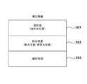
- FIG. 5 is a diagram illustrating a data configuration of measurement information stored in the memory 203.
- a measured value 501 is the amount of water in the body calculated by the current measurement.
- the determination result 502 is information indicating whether the dehydrated state or the non-dehydrated state is determined in step S404 with respect to the in-vivo moisture amount calculated by the current measurement.
- the measurement time 503 is information indicating the time notified from the time measuring unit 224 in the current measurement.
- the measurement time 503 can be, for example, the time notified from the time measuring unit 224 when the measurement is performed in step S402.
- step S406 the water content in the body calculated by the current measurement is displayed on the display unit 112.
- display is performed in a display form according to the determination result of the dehydrated state or the non-dehydrated state (for example, in the case of the dehydrated state, the amount of water in the body is displayed in red, and in the case of the non-dehydrated state, The amount of water in the body is displayed in blue).
- the moisture meter 100 in the present embodiment separates the insertion portion 120 into the proximal insertion portion 120-1 and the distal insertion portion 120-2, and between them,
- the slide mechanism is provided.
- the distal end side insertion portion 120-2 is provided with a side wall portion 181 so as to cover a part of the outer peripheral surface of the proximal end side insertion portion 120-1.
- the sliding mechanism is configured to be liquid-tightly covered with a protective member 151 that can be expanded and contracted in the sliding direction inside the side wall portion 181 of the distal end side insertion portion 120-2.
- FIG. 6 is a diagram showing an external configuration of the in-vivo moisture meter 600 and a configuration of the tip region 661 of the in-vivo moisture meter 600 according to the second embodiment of the present invention.
- the same reference number is attached
- the difference from the first embodiment will be mainly described.
- a seal member 671 is provided on the outer peripheral surface of the proximal insertion portion 120-1 over the entire circumference.
- the seal member 671 includes any seal member such as an O-ring, X ring, V ring, Stirling, lip seal, clearance seal, and the like.
- the side wall portion 181 is provided in the distal end side insertion portion 120-2 to cover a part of the distal end side of the outer peripheral surface of the proximal end insertion portion 120-1.
- the invention is not limited to this.
- the base end side insertion portion 120-1 may be provided with a side wall portion so as to cover a part of the base end side of the outer peripheral surface of the base end side insertion portion 120-2. Details of this embodiment will be described below.
- FIG. 7 is a diagram showing an external configuration of the in-vivo moisture meter 700 and a configuration of the tip region 761 of the in-vivo moisture meter 700 according to the second embodiment of the present invention.
- the same reference number is attached
- the difference from the first embodiment will be mainly described.
- the proximal insertion portion 720-1 has a side wall portion 781, and a part of the outer peripheral surface of the distal insertion portion 720-2. Covering. As a result, the step between the outer peripheral surface of the proximal end side insertion portion 720-1 and the outer peripheral surface of the distal end side insertion portion 720-2 can be reduced as much as possible. It is possible to integrally form the distal end side insertion portion 720-2. As a result, the operator can easily wipe the insertion portion 120.
- a protective member 751 that can be expanded and contracted in the sliding direction is provided inside the proximal-end-side insertion portion 720-1, and covers the sliding mechanism.
- the protective member 751 Even when liquid or the like enters from a gap between the inner peripheral surface of the side wall portion 781 of the proximal end side insertion portion 120-1 and the outer peripheral surface of the distal end side insertion portion 120-2, the protective member 751 Thus, it is possible to avoid the intrusion of liquid or the like into the moisture meter 700 in the body.
- an elastic member such as an elastomer such as silicone, polyurethane, and a styrene-based elastomer, a polyolefin such as polyethylene, and the like can be given.
- coating may be performed with a fluororesin having a trifluoromethyl group (—CF 3) as a functional group.
- the side wall portion 181 is provided in the distal end side insertion portion 120-2, and the side wall of the distal end side insertion portion 120-2 is configured to cover a part of the outer peripheral surface of the proximal end side insertion portion 120-1.
- the gap between the inner peripheral surface of the portion 181 and the outer peripheral surface of the proximal end insertion portion 120-1 is sealed using a seal member, the present invention is not limited to this.
- the proximal end side insertion portion 720 may be sealed using a seal member.
Landscapes
- Health & Medical Sciences (AREA)
- Life Sciences & Earth Sciences (AREA)
- Medical Informatics (AREA)
- Molecular Biology (AREA)
- Radiology & Medical Imaging (AREA)
- Biophysics (AREA)
- Pathology (AREA)
- Engineering & Computer Science (AREA)
- Biomedical Technology (AREA)
- Heart & Thoracic Surgery (AREA)
- Nuclear Medicine, Radiotherapy & Molecular Imaging (AREA)
- Physics & Mathematics (AREA)
- Surgery (AREA)
- Animal Behavior & Ethology (AREA)
- General Health & Medical Sciences (AREA)
- Public Health (AREA)
- Veterinary Medicine (AREA)
- Investigating Or Analyzing Materials By The Use Of Electric Means (AREA)
- Measurement And Recording Of Electrical Phenomena And Electrical Characteristics Of The Living Body (AREA)
- Measuring And Recording Apparatus For Diagnosis (AREA)
Description
本発明は、被検者の生体内の水分量を測定する体内水分計に関するものである。
被検者の生体内の水分量を測定することは重要である。生体における脱水症状は、生体内の水分が減少する病態であり、発汗や体温上昇により多くの水分が体内から体外に排出される運動時や気温の高い時に多く発現する。特に、高齢者の場合、生体の水分保持能力自体が低下しているため、一般健常者と比較して脱水症状を起こし易い。
通常、生体内の水分が体重の3%以上失われた時点で体温調整の障害が起こると言われている。体温調整の障害が起こり体温が上昇すると、生体内の更なる水分の減少を引き起こすため悪循環に陥り、遂には熱中症と称される病態に至ることとなる。熱中症には、熱痙攣、熱疲労、熱射病等の病態があり、時には全身の臓器障害が起こることもある。このようなことから、熱中症に至る危険を未然に回避すべく、生体内の水分量を的確に把握することは重要である。
かかる背景のもと、本願出願人は、生体内の水分量を的確に把握するのに適した部位として、被検者の腋窩に着目しており、当該腋窩に電極を配したセンサ部をあてがい、当該電極間の静電容量を測定することで、被検者の生体内の水分量を算出する体内水分計の開発に取り組んでいる。
図8の8aは、本願出願人が提案している体内水分計800の一例を示す図である。図8の8aに示すように、体内水分計800は本体部810と挿入部820とを備え、測定者によって把持される本体部は、全体として直線状に形成されている。本体部810の筐体表面には、表示部812が配されており、測定結果831等が表示される。一方、腋窩に挿入される挿入部820は本体部810の一端から延設されており、本体部810に対して、全体として、下向きに緩やかに湾曲している。
挿入部820の先端面822には、センサ部821がスライド可能に支持されている。センサ部821は、先端面822に略平行な面を有するセンサヘッド823を有しており、センサヘッド823の皮膚への密着を保証するうえでの押圧力を確保するため、矢印841bの方向へ付勢されている。そして、センサヘッド823が被検者の腋窩の皮膚に押し当てられると、センサ部821が矢印841aの方向に所定量スライドし、これにより測定が開始されることとなる。
しかしながら、上記のような構成を有する体内水分計800の場合、先端面822には、センサ部821を矢印841a方向にスライドさせるための開口部が設けられている。図8の8bは、センサ部821を含む、挿入部820の先端領域850の断面構成を示す図である。
図8の8bに示すように、開口部851は、その開口面が、センサ部821のセンサヘッド823よりも大きく、センサ部821の側面と開口部851の内壁面との間には、隙間852が確保されている。これにより、センサ部821を滑らかにスライドさせることができる。
一方で、センサ部821の側面と開口部851の内壁面との間に隙間852を設けると、当該隙間852を介して体内水分計800の内部に液体(例えば、センサ部821の汚れを拭きとるためのアルコール等)が浸入することとなり、体内水分計800の故障の原因となることが考えられる。
また、当該隙間852を介して体内水分計800の内部に埃や測定時に付着した皮膚片などの汚れが溜まり、体内水分計800の故障や患者どうしの感染の原因となることが考えられる。
本発明は上記課題に鑑みてなされたものであり、センサ部がスライド可能に構成された体内水分計において防水性・防汚性を向上させることを目的とする。
上記の目的を達成するために、本発明に係る体内水分計は以下のような構成を備える。即ち、
体内水分計であって、
直線状に形成された本体部と、
前記本体部の一端から湾曲して延設された挿入部と、を備え、
前記挿入部は、
被検者の体表面に接触させることで、生体内の水分に関するデータを測定するセンサ部が、その先端面に固定された先端側挿入部と、
前記先端側挿入部を、前記先端面に略直交する方向にスライドさせるスライド機構を介して支持する基端側挿入部と、
前記先端側挿入部と前記基端側挿入部との間の前記スライド機構を液密にする保護部材と、を備え、
前記先端側挿入部の基端側には、前記基端側挿入部の外周面の一部を覆う側壁部が形成されており、前記保護部材は、該側壁部の内側に配されていることを特徴とする。
体内水分計であって、
直線状に形成された本体部と、
前記本体部の一端から湾曲して延設された挿入部と、を備え、
前記挿入部は、
被検者の体表面に接触させることで、生体内の水分に関するデータを測定するセンサ部が、その先端面に固定された先端側挿入部と、
前記先端側挿入部を、前記先端面に略直交する方向にスライドさせるスライド機構を介して支持する基端側挿入部と、
前記先端側挿入部と前記基端側挿入部との間の前記スライド機構を液密にする保護部材と、を備え、
前記先端側挿入部の基端側には、前記基端側挿入部の外周面の一部を覆う側壁部が形成されており、前記保護部材は、該側壁部の内側に配されていることを特徴とする。
本発明によれば、センサ部がスライド可能に構成された体内水分計において防水性・防汚性を向上させることが可能となる。
本発明のその他の特徴及び利点は、添付図面を参照とした以下の説明により明らかになるであろう。なお、添付図面においては、同じ若しくは同様の構成には、同じ参照番号を付す。
添付図面は明細書に含まれ、その一部を構成し、本発明の実施の形態を示し、その記述と共に本発明の原理を説明するために用いられる。
図1Aは、本発明の第1の実施形態にかかる体内水分計の外観構成を示す図である。
図1Bは、体内水分計の先端領域の構成を示す図である。
図2は、体内水分計の機能構成を示す図である。
図3は、体内水分計の測定回路の構成例を示す図である。
図4は、体内水分計の動作を説明するための図である。
図5は、測定情報のデータ構成を示す図である。
図6は、本発明の第2の実施形態にかかる体内水分計の外観構成及び体内水分計の先端領域の構成を示す図である。
図7は、本発明の第3の実施形態にかかる体内水分計の外観構成及び体内水分計の先端領域の構成を示す図である。
図8は、体内水分計の外観構成及び体内水分計の先端領域の構成を示す図である。
以下、本発明の各実施形態について図面を参照しながら説明する。なお、以下に述べる実施の形態は、本発明の好適な具体例であるから、技術的に好ましい種々の限定が付されているが、本発明の範囲は、以下の説明において特に本発明を限定する旨の記載がない限り、これらの態様に限られるものではない。
[第1の実施形態]
<1.体内水分計の外観構成>
図1Aは、本発明の第1の実施形態に係る体内水分計100の外観構成を示す図である。体内水分計100は、被検者の体表面である腋窩の皮膚にセンサ部を接触させ、センサ部において、供給した電気信号に応じた物理量を検出することで被検者の体内の水分量を検出する。本実施形態に係る体内水分計100では、当該物理量(生体内の水分に関するデータ)として被検者の静電容量を測定することにより、腋窩の皮膚の湿り具合を検出し、体内の水分量を算出する。
<1.体内水分計の外観構成>
図1Aは、本発明の第1の実施形態に係る体内水分計100の外観構成を示す図である。体内水分計100は、被検者の体表面である腋窩の皮膚にセンサ部を接触させ、センサ部において、供給した電気信号に応じた物理量を検出することで被検者の体内の水分量を検出する。本実施形態に係る体内水分計100では、当該物理量(生体内の水分に関するデータ)として被検者の静電容量を測定することにより、腋窩の皮膚の湿り具合を検出し、体内の水分量を算出する。
図1Aに示すように、体内水分計100は本体部110と、本体部110の一端から湾曲して延設された挿入部120とを備える。本体部110は、上面114、下面115、側面116、117がそれぞれ長軸方向(不図示)に略平行に形成されており、全体として、直線状に形成されている。また、本体部110の筐体表面には、各種ユーザインターフェースが配置され、筐体内部には体内の水分量を算出するための電子回路が収納されている。
図1Aの例では、ユーザインターフェースとして、電源スイッチ111及び表示部112が示されている。電源スイッチ111は、本体部110の後端面113の凹部に配されている。このように凹部に電源スイッチ111を配する構成とすることで、電源スイッチ111の誤操作を防ぐことができる。なお、電源スイッチ111がオンされると後述の電源部211(図2)から体内水分計100の各部への電源供給が開始され、体内水分計100は動作状態となる。
表示部112は、本体部110の側面117上において、長軸方向のやや前方側に配されている。これは、体内水分計100を用いて被検者の体内の水分量を測定するにあたり、測定者が把持領域118を把持した場合であっても、測定者の把持した手で表示部112が完全に覆われることがないようにするためである(把持した状態でも測定結果が視認できるようにするためである)。
表示部112には、今回の水分量の測定結果131が表示される。また、参考として前回の測定結果132もあわせて表示される。さらに、電池表示部133には、電池(図2の電源部211)の残量が表示される。また、無効な測定結果が得られた場合や測定エラーが検出された場合には、表示部112に“E”が表示され、その旨が測定者に報知される。なお、表示部112に表示される文字等は、本体部110の上面114側を上とし、下面115側を下として、表示されるものとする。
体内水分計100の挿入部120は、上面124及び下面125が曲面形状を有しており、本体部110に対して、全体として、下向きに緩やかに湾曲している。
挿入部120の先端面122には、センサ部121が固定されている。センサ部121は、先端面122に略平行な面を有するセンサヘッド123を有している。
なお、挿入部120は、本体部110と接続された基端側挿入部120-1と、センサ部121が固定された先端側挿入部120-2とに分離されており、先端側挿入部120-2は、センサヘッド123の皮膚への密着を保証する上での押圧力を確保するため、ばね等の弾性部材により、矢印141b方向に付勢されている(たとえば150gf程度の付勢力)。そして、センサヘッド123が被検者の腋窩の皮膚に押し当てられると、先端側挿入部120-2全体が、矢印141a方向(先端面122と略直交する方向、すなわち先端面122の法線方向)に所定量(例えば、1mm~10mm、本実施形態では3mm)スライドし、これにより測定が開始されることとなる(以下、矢印141aの方向をスライド方向と称す)。なお、体内水分計100の先端領域(点線161で示す領域)の詳細構成は後述する)。
かかる構成のもと、測定者が電源スイッチ111をオンして体内水分計100を動作状態とした後、センサヘッド123が被検者の腋窩に押し当てられたことが検知されると、体内水分量の測定が開始される。あるいは、測定者が電源スイッチ111をオンして体内水分計100を動作状態とした後、センサヘッド123が被検者の腋窩に所定負荷(例えば20gf~200gf、さらに好ましくは100gf~190gf、本実施形態では150gf)で押し当てられたことが検知されると、体内水分量の測定が開始される。このような仕組みにより、測定時におけるセンサヘッド123の腋窩への密着の程度を一定にすることができる。
<2.体内水分計の先端領域の構成>
次に、体内水分計100の先端領域(図1Aの点線161で示す領域)の詳細構成について説明する。図1Bは、体内水分計100の先端領域の構成を示す図であり、先端側挿入部120-2と基端側挿入部120-1との間の接続構成がわかるように示した図である。
次に、体内水分計100の先端領域(図1Aの点線161で示す領域)の詳細構成について説明する。図1Bは、体内水分計100の先端領域の構成を示す図であり、先端側挿入部120-2と基端側挿入部120-1との間の接続構成がわかるように示した図である。
図1Bに示すように、先端側挿入部120-2には、側壁部181が設けられており、先端側挿入部120-2の外周面の一部(先端側)を覆うように構成されている。つまり、本体部110に対して下向きに緩やかに湾曲し先端に向かって細くなる挿入部120において、基端側挿入部120-1の外周面と先端側挿入部120-2の外周面とが一体的になるよう構成されている。
このように、先端側挿入部120-2に側壁部181を設け、基端側挿入部120-1の外周面と一体的になるよう構成することにより、測定者は、挿入部120に付着した汚れを拭き取る際の拭き取り作業を容易に行うことができる。
先端側挿入部120-2の側壁部181内部において、基端側挿入部120-1には支持部材171が配され、先端側挿入部120-2をスライド可能に支持する。また、ばね等の弾性部材172が配され、先端側挿入部120-2を矢印141b方向に付勢する。なお、先端側挿入部120-2をスライドさせるための機構(スライド機構)は、保護部材151により覆われている。
このように、先端側挿入部120-2のスライド機構を、保護部材151の内側に配する構成とすることで、スライド機構を介して体内水分計100内部へ液体が浸入することを防ぐことができる。つまり、体内水分計100の防水性・防汚性を向上させることができる。
なお、保護部材151は、スライド方向に伸縮可能であり、センサヘッド123が被検者の腋窩の皮膚に押し当てられ、弾性部材172による付勢力に抗して押圧されることで、先端側挿入部120-2が矢印141a方向にスライドすると、保護部材151はスライド方向に縮む(紙面右側参照)。
このように、保護部材151をスライド方向に伸縮可能な構成とすることで、先端側挿入部120-2のスライド動作が、保護部材151によって妨げられることがなくなるため、測定者は、一定の押圧力で押圧することができる。なお、保護部材151の好ましい材料としては、例えば、シリコーン、ポリウレタン、スチレン系エラストマーなどのエラストマー、ポリエチレンなどのポリオレフィン、等の弾性部材が挙げられる。更に、防汚性を持たせるために、官能基としてトリフルオロメチル基(-CF3)を有するフッ素系樹脂でコーティングしてもよい。
<3.体内水分計の機能構成>
次に、体内水分計100の機能構成について説明する。図2は、体内水分計100の機能構成を示す図である。図2において、制御部201は、CPU202、メモリ203を有し、CPU202はメモリ203に格納されているプログラムを実行することにより、体内水分計100における種々の制御を実行する。
次に、体内水分計100の機能構成について説明する。図2は、体内水分計100の機能構成を示す図である。図2において、制御部201は、CPU202、メモリ203を有し、CPU202はメモリ203に格納されているプログラムを実行することにより、体内水分計100における種々の制御を実行する。
例えば、CPU202は、図4のフローチャートにより後述する表示部112の表示制御、ブザー222やLEDランプ223の駆動制御、体内水分量の測定(本実施形態では静電容量測定)などを実行する。メモリ203は、不揮発性メモリと揮発性メモリとを含み、不揮発性メモリはプログラムメモリとして、揮発性メモリはCPU202の作業メモリとして利用される。
電源部211は、交換が可能なバッテリー、或いは充電が可能なバッテリーを有しており、体内水分計100の各部へ電源を供給する。電圧レギュレータ212は、制御部201等へ一定電圧(例えば、2.3V)を供給する。電池残量検出部213は、電源部211から供給される電圧値に基づいて、電池の残量を検出し、その検出結果を制御部201に通知する。制御部201は、電池残量検出部213からの電池残量検出信号に基づいて、電池表示部133の表示を制御する。
電源スイッチ111が押下されると、各部への電源部211からの電力供給が開始される。そして、制御部201は、電源スイッチ111の測定者による押下が1秒以上継続したことを検出すると、電源部211からの各部への電源供給を維持させ、体内水分計100を動作状態とする。上述したように、測定スイッチ214は、電源部211からの電力供給が開始されると同時にオン状態になる。制御部201は、先端側挿入部120-2が矢印141aの方向へ所定量以上押されると水分量の測定を開始し、測定スイッチ214のオン状態が所定時間(例えば2秒)継続すると、測定を終了する。なお、電源部211の消耗を防止するために、体内水分計100が動作状態になってから2分経過しても測定開始とならない場合は、制御部201は自動的に体内水分計100を電源オフの状態へと移行させる。
測定回路221は、センサヘッド123と接続され、静電容量を測定する。図3は、測定回路221の構成例を示す図である。図3に示すように、インバータ301、302、抵抗303、304、被検者容量310によりCR発振回路が形成される。被検者容量310によって出力信号305の発振周波数が変化するので、制御部201は、出力信号305の周波数を測定することにより、被検者容量310を算出する。なお、本実施形態のセンサヘッド123は、2つの櫛形の電極が、それぞれの櫛歯が互い違いに並ぶように配置されてなるものとする。
図2に戻る。表示部112は、図1で説明したような表示を制御部201の制御下で行う。ブザー222は、先端側挿入部120-2の押下による測定の開始や、体内水分量の測定が完了した際に鳴動し、測定の開始や完了を測定者に通知する。LEDランプ223もブザー222と同様の通知を行う。すなわち、LEDランプ223は、先端側挿入部120-2の押下による測定の開始や、体内水分量の測定が完了した際に点灯し、測定の開始や完了を測定者に通知する。計時部224は、電源がオフの状態であっても電源部211からの電源供給を受けて動作し、動作状態においては時刻を制御部201に通知する。
<4.体内水分計の動作>
以上のような構成を備えた、本実施形態に係る体内水分計100の動作を、図4のフローチャートを参照して説明する。
以上のような構成を備えた、本実施形態に係る体内水分計100の動作を、図4のフローチャートを参照して説明する。
ステップS401では、制御部201が、測定開始の指示を検出する。本実施形態では、測定スイッチ214の状態を監視し、測定スイッチ214のオン状態が2秒以上継続した場合に測定開始の指示を検出したと判定する。制御部201は、測定開始の指示を検出すると、ステップS402において、測定回路221からの出力信号305の発振周波数を測定する。
ステップS403では、ステップS402において測定された出力信号305の発振周波数に基づいて、被検者の体内水分量を算出する。
ステップS404では、ステップS403で算出された体内水分量が所定の閾値を超えるか否かに基づいて被検者が脱水状態か否かを判定する。なお、この場合の閾値とは、例えば、水を100%、空気を0%とした時の35%に相当する値が望ましい。
ステップS405では、今回の測定情報をメモリ203に格納する。図5は、メモリ203に格納される測定情報のデータ構成を示す図である。図5において、測定値501は、今回の測定により算出された体内水分量である。判定結果502は、今回の測定により算出された体内水分量に対して、ステップS404において判定された、脱水状態か非脱水状態かを示す情報である。測定時刻503は、今回の測定において計時部224から通知された時刻を示す情報である。測定時刻503としては、例えば、ステップS402において測定を実行した時点で計時部224から通知されている時刻とすることができる。
ステップS406では、今回の測定により算出された体内水分量を表示部112に表示する。このとき、脱水状態か非脱水状態かの判定結果に応じた表示形態により表示を行う(例えば、脱水状態の場合には、赤色にて体内水分量を表示し、非脱水状態の場合には、青色にて体内水分量を表示する)。
以上の説明から明らかなように、本実施形態に係る体内水分計100は、挿入部120を、基端側挿入部120-1と先端側挿入部120-2とに分離し、両者の間にスライド機構を設ける構成とした。また、先端側挿入部120-2に側壁部181を設け、基端側挿入部120-1の外周面の一部を覆う構成とした。更に、先端側挿入部120-2の側壁部181の内部において、スライド機構を、スライド方向に伸縮可能な保護部材151に液密に覆う構成とした。
これにより、体内水分計100の防水性・防汚性を向上させることが可能となった。また、挿入部120に汚れが付着した場合であっても、容易に拭き取り作業を行うことが可能となった。更に、スライド動作が保護部材によって妨げられることがなく、測定者は、一定の押圧力で押圧することができるようになった。
[第2の実施形態]
上記第1の実施形態では、スライド方向に伸縮可能な保護部材を、スライド機構の周囲に配することで、防水性・防汚性を向上させる構成としたが、本発明はこれに限定されない。例えば、先端側挿入部の側壁部の内周面と基端側挿入部の外周面との間の隙間を、シール部材を用いてシールすることにより防水性・防汚性を向上させるようにしてもよい。以下、本実施形態の詳細を説明する。
上記第1の実施形態では、スライド方向に伸縮可能な保護部材を、スライド機構の周囲に配することで、防水性・防汚性を向上させる構成としたが、本発明はこれに限定されない。例えば、先端側挿入部の側壁部の内周面と基端側挿入部の外周面との間の隙間を、シール部材を用いてシールすることにより防水性・防汚性を向上させるようにしてもよい。以下、本実施形態の詳細を説明する。
図6は、本発明の第2の実施形態に係る体内水分計600の外観構成及び体内水分計600の先端領域661の構成を示す図である。なお、上記第1の実施形態において図1A及び図1Bを用いて説明した構成と同じ構成については、同じ参照番号を付し、ここでは説明を省略する。以下、上記第1の実施形態との相違点を中心に説明する。
図6の6bに示すように、本実施形態に係る体内水分計600の場合、基端側挿入部120-1の外周面と、先端側挿入部120-2の側壁部の内周面との間の隙間をシールするために、基端側挿入部120-1の外周面には、全周にわたってシール部材671が設けられている。
これにより、基端側挿入部120-1の外周面と、先端側挿入部120-2の側壁部181の内周面との間の隙間から、液体等が浸入することを防ぐことができる。
なお、シール部材671としては、O-リング、Xリング、Vリング、スターリング、リップシール、クリアランスシール等、任意のシール部材が含まれるものとする。
[第3の実施形態]
上記第1及び第2の実施形態では、先端側挿入部120-2に側壁部181を設け、基端側挿入部120-1の外周面の先端側の一部を覆う構成としたが、本発明はこれに限定されない。例えば、基端側挿入部120-1に側壁部を設け、基端側挿入部120-2の外周面の基端側の一部を覆う構成としてもよい。以下、本実施形態の詳細を説明する。
上記第1及び第2の実施形態では、先端側挿入部120-2に側壁部181を設け、基端側挿入部120-1の外周面の先端側の一部を覆う構成としたが、本発明はこれに限定されない。例えば、基端側挿入部120-1に側壁部を設け、基端側挿入部120-2の外周面の基端側の一部を覆う構成としてもよい。以下、本実施形態の詳細を説明する。
図7は、本発明の第2の実施形態に係る体内水分計700の外観構成及び体内水分計700の先端領域761の構成を示す図である。なお、上記第1の実施形態において図1A及び図1Bを用いて説明した構成と同じ構成については、同じ参照番号を付し、ここでも説明は省略する。以下、上記第1の実施形態との相違点を中心に説明する。
図7の7bに示すように、本実施形態にかかる体内水分計700の場合、基端側挿入部720-1は側壁部781を有し、先端側挿入部720-2の外周面の一部を覆っている。これにより、基端側挿入部720-1の外周面と先端側挿入部720-2の外周面との間の段差を極力小さくすることができようになり、基端側挿入部720-1と先端側挿入部720-2とを一体的に構成することが可能となる。この結果、測定者による挿入部120の拭き取り作業が容易となる。
なお、上記第1の実施形態と同様に、基端側挿入部720-1の内側には、スライド方向に伸縮可能な保護部材751が設けられており、スライド機構を覆っている。これにより、基端側挿入部120-1の側壁部781の内周面と先端側挿入部120-2の外周面との間の隙間から液体等が浸入した場合であっても、保護部材751により、体内水分計700内部への液体等の浸入を回避することが可能となる。
なお、保護部材751の好ましい材料としては、例えば、シリコーン、ポリウレタン、スチレン系エラストマーなどのエラストマー、ポリエチレンなどのポリオレフィン、等の弾性部材が挙げられる。更に、防汚性を持たせるために、官能基としてトリフルオロメチル基(-CF3)を有するフッ素系樹脂でコーティングしてもよい。
[第4の実施形態]
上記第2の実施形態では、先端側挿入部120-2に側壁部181を設け、基端側挿入部120-1の外周面の一部を覆う構成において、先端側挿入部120-2の側壁部181の内周面と基端側挿入部120-1の外周面との間の隙間を、シール部材を用いてシールする構成としたが、本発明はこれに限定されない。
上記第2の実施形態では、先端側挿入部120-2に側壁部181を設け、基端側挿入部120-1の外周面の一部を覆う構成において、先端側挿入部120-2の側壁部181の内周面と基端側挿入部120-1の外周面との間の隙間を、シール部材を用いてシールする構成としたが、本発明はこれに限定されない。
例えば、第3の実施形態のように、基端側挿入部720-1に側壁部781を設け、先端側挿入部720-2の外周面の一部を覆う構成において、基端側挿入部720-1の側壁部781の内周面と先端側挿入部720-2の外周面との間の隙間を、シール部材を用いてシールするように構成してもよい。
本発明は上記実施の形態に制限されるものではなく、本発明の精神及び範囲から離脱することなく、様々な変更及び変形が可能である。従って、本発明の範囲を公にするために、以下の請求項を添付する。
Claims (5)
- 体内水分計であって、
直線状に形成された本体部と、
前記本体部の一端から湾曲して延設された挿入部と、を備え、
前記挿入部は、
被検者の体表面に接触させることで、生体内の水分に関するデータを測定するセンサ部が、その先端面に固定された先端側挿入部と、
前記先端側挿入部を、前記先端面に略直交する方向にスライドさせるスライド機構を介して支持する基端側挿入部と、
前記先端側挿入部と前記基端側挿入部との間の前記スライド機構を液密にする保護部材と、を備え、
前記先端側挿入部の基端側には、前記基端側挿入部の外周面の一部を覆う側壁部が形成されており、前記保護部材は、該側壁部の内側に配されていることを特徴とする体内水分計。 - 体内水分計であって、
直線状に形成された本体部と、
前記本体部の一端から湾曲して延設された挿入部と、を備え、
前記挿入部は、
被検者の体表面に接触させることで、生体内の水分に関するデータを測定するセンサ部が、その先端面に固定された先端側挿入部と、
前記先端側挿入部を、前記先端面に略直交する方向にスライドさせるスライド機構を介して支持する基端側挿入部と、
前記先端側挿入部と前記基端側挿入部との間の前記スライド機構を液密にする保護部材と、を備え、
前記基端側挿入部の先端側には、前記先端側挿入部の外周面の一部を覆う側壁部が形成されており、前記保護部材は、該側壁部の内側に配されていることを特徴とする体内水分計。 - 前記保護部材は、前記スライドの方向に伸縮可能に構成されていることを特徴とする請求項1または2に記載の体内水分計。
- 体内水分計であって、
直線状に形成された本体部と、
前記本体部の一端から湾曲して延設された挿入部と、を備え、
前記挿入部は、
被検者の体表面に接触させることで、生体内の水分に関するデータを測定するセンサ部が、その先端面に固定された先端側挿入部と、
前記先端側挿入部を、前記先端面に略直交する方向にスライドさせるスライド機構を介して支持する基端側挿入部と、を備え、
前記先端側挿入部の基端側には、前記基端側挿入部の外周面の一部を覆う側壁部が形成されており、前記基端側挿入部の外周面には、該側壁部との間の隙間をシールするシール部材が全周に配されていることを特徴とする体内水分計。 - 体内水分計であって、
直線状に形成された本体部と、
前記本体部の一端から湾曲して延設された挿入部と、を備え、
前記挿入部は、
被検者の体表面に接触させることで、生体内の水分に関するデータを測定するセンサ部が、その先端面に固定された先端側挿入部と、
前記先端側挿入部を、前記先端面に略直交する方向にスライドさせるスライド機構を介して支持する基端側挿入部と、を備え、
前記基端側挿入部の先端側には、前記先端側挿入部の外周面の一部を覆う側壁部が形成されており、前記側壁部の内周面には、前記先端側挿入部の外周面との間の隙間をシールするシール部材が全周に配されていることを特徴とする体内水分計。
Priority Applications (3)
| Application Number | Priority Date | Filing Date | Title |
|---|---|---|---|
| CN201280074415.2A CN104411235B (zh) | 2012-08-14 | 2012-08-14 | 体内水分计 |
| JP2014530393A JP5993015B2 (ja) | 2012-08-14 | 2012-08-14 | 体内水分計 |
| PCT/JP2012/005153 WO2014027378A1 (ja) | 2012-08-14 | 2012-08-14 | 体内水分計 |
Applications Claiming Priority (1)
| Application Number | Priority Date | Filing Date | Title |
|---|---|---|---|
| PCT/JP2012/005153 WO2014027378A1 (ja) | 2012-08-14 | 2012-08-14 | 体内水分計 |
Publications (1)
| Publication Number | Publication Date |
|---|---|
| WO2014027378A1 true WO2014027378A1 (ja) | 2014-02-20 |
Family
ID=50101285
Family Applications (1)
| Application Number | Title | Priority Date | Filing Date |
|---|---|---|---|
| PCT/JP2012/005153 Ceased WO2014027378A1 (ja) | 2012-08-14 | 2012-08-14 | 体内水分計 |
Country Status (3)
| Country | Link |
|---|---|
| JP (1) | JP5993015B2 (ja) |
| CN (1) | CN104411235B (ja) |
| WO (1) | WO2014027378A1 (ja) |
Citations (3)
| Publication number | Priority date | Publication date | Assignee | Title |
|---|---|---|---|---|
| JP2000051153A (ja) * | 1998-08-11 | 2000-02-22 | Kanebo Ltd | 皮膚状態評価方法およびそれに用いる装置 |
| JP2009153727A (ja) * | 2007-12-27 | 2009-07-16 | Kao Corp | 皮膚性状測定用多機能プローブ |
| WO2012042878A1 (ja) * | 2010-09-29 | 2012-04-05 | テルモ株式会社 | 水分計 |
Family Cites Families (7)
| Publication number | Priority date | Publication date | Assignee | Title |
|---|---|---|---|---|
| JPS59139261A (ja) * | 1983-01-31 | 1984-08-10 | 松下電工株式会社 | 振動マツサ−ジ機 |
| JP3688811B2 (ja) * | 1995-11-30 | 2005-08-31 | 株式会社モリテックス | 油水分測定装置 |
| US20080287750A1 (en) * | 2002-01-04 | 2008-11-20 | Dune Medical Devices Ltd. | Ergonomic probes |
| JP2005205041A (ja) * | 2004-01-23 | 2005-08-04 | Horiba Ltd | 接触式測定器のセンサ部保持構造 |
| JP3120546U (ja) * | 2005-03-31 | 2006-04-13 | バイオスペース・カンパニー・リミテッド | 体成分分析結果シート |
| CN201001730Y (zh) * | 2007-01-19 | 2008-01-09 | 廖植生 | 皮肤水分测试笔 |
| JP2012090878A (ja) * | 2010-10-28 | 2012-05-17 | Terumo Corp | 水分計 |
-
2012
- 2012-08-14 WO PCT/JP2012/005153 patent/WO2014027378A1/ja not_active Ceased
- 2012-08-14 CN CN201280074415.2A patent/CN104411235B/zh active Active
- 2012-08-14 JP JP2014530393A patent/JP5993015B2/ja active Active
Patent Citations (3)
| Publication number | Priority date | Publication date | Assignee | Title |
|---|---|---|---|---|
| JP2000051153A (ja) * | 1998-08-11 | 2000-02-22 | Kanebo Ltd | 皮膚状態評価方法およびそれに用いる装置 |
| JP2009153727A (ja) * | 2007-12-27 | 2009-07-16 | Kao Corp | 皮膚性状測定用多機能プローブ |
| WO2012042878A1 (ja) * | 2010-09-29 | 2012-04-05 | テルモ株式会社 | 水分計 |
Also Published As
| Publication number | Publication date |
|---|---|
| JP5993015B2 (ja) | 2016-09-14 |
| JPWO2014027378A1 (ja) | 2016-07-25 |
| CN104411235B (zh) | 2017-05-24 |
| CN104411235A (zh) | 2015-03-11 |
Similar Documents
| Publication | Publication Date | Title |
|---|---|---|
| JP5993014B2 (ja) | 体内水分計 | |
| JP4706782B2 (ja) | 体脂肪測定装置 | |
| JP5883151B2 (ja) | 体内水分計および表示制御方法 | |
| HK1219040A1 (zh) | 体内水分计及体内水分计的显示控制方法 | |
| JPWO2013018295A1 (ja) | 体内水分計 | |
| WO2013140714A1 (ja) | 体内水分計 | |
| JP5993015B2 (ja) | 体内水分計 | |
| JP5917911B2 (ja) | 体内水分計および表示制御方法 | |
| WO2014128743A1 (ja) | 体内水分計及び端末 | |
| CN103648377B (zh) | 体内水分计及其显示控制方法 | |
| WO2013132798A1 (ja) | 体内水分計及びその基準器 | |
| JP2013192893A (ja) | 体内水分計 | |
| JP5426518B2 (ja) | 体脂肪測定装置 | |
| JPWO2014027379A1 (ja) | 体内水分計 | |
| JP5993013B2 (ja) | 体内水分計、体内水分計の制御方法、および記憶媒体 | |
| WO2014049631A1 (ja) | 体内水分計 | |
| JP5941170B2 (ja) | 体内水分計 | |
| JP2013066565A (ja) | 体内水分計及びその制御方法 | |
| JP2013192650A (ja) | 体内水分計 | |
| WO2013136659A1 (ja) | 体内水分計 | |
| JPWO2014041584A1 (ja) | 体内水分計および表示制御方法 | |
| JP2013172770A (ja) | 体内水分計及びそのセンサ部保護用カバー | |
| JP2013132517A (ja) | 体内水分計 | |
| JP2013132515A (ja) | 体内水分計 | |
| TWI505809B (zh) | 體內水分計及其顯示控制方法 |
Legal Events
| Date | Code | Title | Description |
|---|---|---|---|
| 121 | Ep: the epo has been informed by wipo that ep was designated in this application |
Ref document number: 12882982 Country of ref document: EP Kind code of ref document: A1 |
|
| ENP | Entry into the national phase |
Ref document number: 2014530393 Country of ref document: JP Kind code of ref document: A |
|
| NENP | Non-entry into the national phase |
Ref country code: DE |
|
| 122 | Ep: pct application non-entry in european phase |
Ref document number: 12882982 Country of ref document: EP Kind code of ref document: A1 |