WO2014025017A1 - 透明酸化物膜形成用スパッタリングターゲット及びその製造方法 - Google Patents
透明酸化物膜形成用スパッタリングターゲット及びその製造方法 Download PDFInfo
- Publication number
- WO2014025017A1 WO2014025017A1 PCT/JP2013/071670 JP2013071670W WO2014025017A1 WO 2014025017 A1 WO2014025017 A1 WO 2014025017A1 JP 2013071670 W JP2013071670 W JP 2013071670W WO 2014025017 A1 WO2014025017 A1 WO 2014025017A1
- Authority
- WO
- WIPO (PCT)
- Prior art keywords
- powder
- sputtering target
- oxide film
- forming
- transparent oxide
- Prior art date
- Legal status (The legal status is an assumption and is not a legal conclusion. Google has not performed a legal analysis and makes no representation as to the accuracy of the status listed.)
- Ceased
Links
Images


Classifications
-
- C—CHEMISTRY; METALLURGY
- C23—COATING METALLIC MATERIAL; COATING MATERIAL WITH METALLIC MATERIAL; CHEMICAL SURFACE TREATMENT; DIFFUSION TREATMENT OF METALLIC MATERIAL; COATING BY VACUUM EVAPORATION, BY SPUTTERING, BY ION IMPLANTATION OR BY CHEMICAL VAPOUR DEPOSITION, IN GENERAL; INHIBITING CORROSION OF METALLIC MATERIAL OR INCRUSTATION IN GENERAL
- C23C—COATING METALLIC MATERIAL; COATING MATERIAL WITH METALLIC MATERIAL; SURFACE TREATMENT OF METALLIC MATERIAL BY DIFFUSION INTO THE SURFACE, BY CHEMICAL CONVERSION OR SUBSTITUTION; COATING BY VACUUM EVAPORATION, BY SPUTTERING, BY ION IMPLANTATION OR BY CHEMICAL VAPOUR DEPOSITION, IN GENERAL
- C23C14/00—Coating by vacuum evaporation, by sputtering or by ion implantation of the coating forming material
- C23C14/22—Coating by vacuum evaporation, by sputtering or by ion implantation of the coating forming material characterised by the process of coating
- C23C14/34—Sputtering
- C23C14/3407—Cathode assembly for sputtering apparatus, e.g. Target
-
- C—CHEMISTRY; METALLURGY
- C04—CEMENTS; CONCRETE; ARTIFICIAL STONE; CERAMICS; REFRACTORIES
- C04B—LIME, MAGNESIA; SLAG; CEMENTS; COMPOSITIONS THEREOF, e.g. MORTARS, CONCRETE OR LIKE BUILDING MATERIALS; ARTIFICIAL STONE; CERAMICS; REFRACTORIES; TREATMENT OF NATURAL STONE
- C04B35/00—Shaped ceramic products characterised by their composition; Ceramics compositions; Processing powders of inorganic compounds preparatory to the manufacturing of ceramic products
- C04B35/01—Shaped ceramic products characterised by their composition; Ceramics compositions; Processing powders of inorganic compounds preparatory to the manufacturing of ceramic products based on oxide ceramics
- C04B35/16—Shaped ceramic products characterised by their composition; Ceramics compositions; Processing powders of inorganic compounds preparatory to the manufacturing of ceramic products based on oxide ceramics based on silicates other than clay
-
- C—CHEMISTRY; METALLURGY
- C04—CEMENTS; CONCRETE; ARTIFICIAL STONE; CERAMICS; REFRACTORIES
- C04B—LIME, MAGNESIA; SLAG; CEMENTS; COMPOSITIONS THEREOF, e.g. MORTARS, CONCRETE OR LIKE BUILDING MATERIALS; ARTIFICIAL STONE; CERAMICS; REFRACTORIES; TREATMENT OF NATURAL STONE
- C04B35/00—Shaped ceramic products characterised by their composition; Ceramics compositions; Processing powders of inorganic compounds preparatory to the manufacturing of ceramic products
- C04B35/01—Shaped ceramic products characterised by their composition; Ceramics compositions; Processing powders of inorganic compounds preparatory to the manufacturing of ceramic products based on oxide ceramics
- C04B35/453—Shaped ceramic products characterised by their composition; Ceramics compositions; Processing powders of inorganic compounds preparatory to the manufacturing of ceramic products based on oxide ceramics based on zinc, tin, or bismuth oxides or solid solutions thereof with other oxides, e.g. zincates, stannates or bismuthates
-
- C—CHEMISTRY; METALLURGY
- C04—CEMENTS; CONCRETE; ARTIFICIAL STONE; CERAMICS; REFRACTORIES
- C04B—LIME, MAGNESIA; SLAG; CEMENTS; COMPOSITIONS THEREOF, e.g. MORTARS, CONCRETE OR LIKE BUILDING MATERIALS; ARTIFICIAL STONE; CERAMICS; REFRACTORIES; TREATMENT OF NATURAL STONE
- C04B35/00—Shaped ceramic products characterised by their composition; Ceramics compositions; Processing powders of inorganic compounds preparatory to the manufacturing of ceramic products
- C04B35/622—Forming processes; Processing powders of inorganic compounds preparatory to the manufacturing of ceramic products
- C04B35/64—Burning or sintering processes
- C04B35/645—Pressure sintering
-
- C—CHEMISTRY; METALLURGY
- C23—COATING METALLIC MATERIAL; COATING MATERIAL WITH METALLIC MATERIAL; CHEMICAL SURFACE TREATMENT; DIFFUSION TREATMENT OF METALLIC MATERIAL; COATING BY VACUUM EVAPORATION, BY SPUTTERING, BY ION IMPLANTATION OR BY CHEMICAL VAPOUR DEPOSITION, IN GENERAL; INHIBITING CORROSION OF METALLIC MATERIAL OR INCRUSTATION IN GENERAL
- C23C—COATING METALLIC MATERIAL; COATING MATERIAL WITH METALLIC MATERIAL; SURFACE TREATMENT OF METALLIC MATERIAL BY DIFFUSION INTO THE SURFACE, BY CHEMICAL CONVERSION OR SUBSTITUTION; COATING BY VACUUM EVAPORATION, BY SPUTTERING, BY ION IMPLANTATION OR BY CHEMICAL VAPOUR DEPOSITION, IN GENERAL
- C23C14/00—Coating by vacuum evaporation, by sputtering or by ion implantation of the coating forming material
- C23C14/06—Coating by vacuum evaporation, by sputtering or by ion implantation of the coating forming material characterised by the coating material
- C23C14/08—Oxides
- C23C14/086—Oxides of zinc, germanium, cadmium, indium, tin, thallium or bismuth
-
- C—CHEMISTRY; METALLURGY
- C23—COATING METALLIC MATERIAL; COATING MATERIAL WITH METALLIC MATERIAL; CHEMICAL SURFACE TREATMENT; DIFFUSION TREATMENT OF METALLIC MATERIAL; COATING BY VACUUM EVAPORATION, BY SPUTTERING, BY ION IMPLANTATION OR BY CHEMICAL VAPOUR DEPOSITION, IN GENERAL; INHIBITING CORROSION OF METALLIC MATERIAL OR INCRUSTATION IN GENERAL
- C23C—COATING METALLIC MATERIAL; COATING MATERIAL WITH METALLIC MATERIAL; SURFACE TREATMENT OF METALLIC MATERIAL BY DIFFUSION INTO THE SURFACE, BY CHEMICAL CONVERSION OR SUBSTITUTION; COATING BY VACUUM EVAPORATION, BY SPUTTERING, BY ION IMPLANTATION OR BY CHEMICAL VAPOUR DEPOSITION, IN GENERAL
- C23C14/00—Coating by vacuum evaporation, by sputtering or by ion implantation of the coating forming material
- C23C14/22—Coating by vacuum evaporation, by sputtering or by ion implantation of the coating forming material characterised by the process of coating
- C23C14/34—Sputtering
- C23C14/3407—Cathode assembly for sputtering apparatus, e.g. Target
- C23C14/3414—Metallurgical or chemical aspects of target preparation, e.g. casting, powder metallurgy
-
- G—PHYSICS
- G11—INFORMATION STORAGE
- G11B—INFORMATION STORAGE BASED ON RELATIVE MOVEMENT BETWEEN RECORD CARRIER AND TRANSDUCER
- G11B7/00—Recording or reproducing by optical means, e.g. recording using a thermal beam of optical radiation by modifying optical properties or the physical structure, reproducing using an optical beam at lower power by sensing optical properties; Record carriers therefor
- G11B7/24—Record carriers characterised by shape, structure or physical properties, or by the selection of the material
- G11B7/241—Record carriers characterised by shape, structure or physical properties, or by the selection of the material characterised by the selection of the material
- G11B7/252—Record carriers characterised by shape, structure or physical properties, or by the selection of the material characterised by the selection of the material of layers other than recording layers
- G11B7/254—Record carriers characterised by shape, structure or physical properties, or by the selection of the material characterised by the selection of the material of layers other than recording layers of protective topcoat layers
-
- G—PHYSICS
- G11—INFORMATION STORAGE
- G11B—INFORMATION STORAGE BASED ON RELATIVE MOVEMENT BETWEEN RECORD CARRIER AND TRANSDUCER
- G11B7/00—Recording or reproducing by optical means, e.g. recording using a thermal beam of optical radiation by modifying optical properties or the physical structure, reproducing using an optical beam at lower power by sensing optical properties; Record carriers therefor
- G11B7/24—Record carriers characterised by shape, structure or physical properties, or by the selection of the material
- G11B7/26—Apparatus or processes specially adapted for the manufacture of record carriers
-
- G—PHYSICS
- G11—INFORMATION STORAGE
- G11B—INFORMATION STORAGE BASED ON RELATIVE MOVEMENT BETWEEN RECORD CARRIER AND TRANSDUCER
- G11B7/00—Recording or reproducing by optical means, e.g. recording using a thermal beam of optical radiation by modifying optical properties or the physical structure, reproducing using an optical beam at lower power by sensing optical properties; Record carriers therefor
- G11B7/24—Record carriers characterised by shape, structure or physical properties, or by the selection of the material
- G11B7/26—Apparatus or processes specially adapted for the manufacture of record carriers
- G11B7/266—Sputtering or spin-coating layers
-
- C—CHEMISTRY; METALLURGY
- C04—CEMENTS; CONCRETE; ARTIFICIAL STONE; CERAMICS; REFRACTORIES
- C04B—LIME, MAGNESIA; SLAG; CEMENTS; COMPOSITIONS THEREOF, e.g. MORTARS, CONCRETE OR LIKE BUILDING MATERIALS; ARTIFICIAL STONE; CERAMICS; REFRACTORIES; TREATMENT OF NATURAL STONE
- C04B2235/00—Aspects relating to ceramic starting mixtures or sintered ceramic products
- C04B2235/02—Composition of constituents of the starting material or of secondary phases of the final product
- C04B2235/30—Constituents and secondary phases not being of a fibrous nature
- C04B2235/32—Metal oxides, mixed metal oxides, or oxide-forming salts thereof, e.g. carbonates, nitrates, (oxy)hydroxides, chlorides
- C04B2235/3217—Aluminum oxide or oxide forming salts thereof, e.g. bauxite, alpha-alumina
-
- C—CHEMISTRY; METALLURGY
- C04—CEMENTS; CONCRETE; ARTIFICIAL STONE; CERAMICS; REFRACTORIES
- C04B—LIME, MAGNESIA; SLAG; CEMENTS; COMPOSITIONS THEREOF, e.g. MORTARS, CONCRETE OR LIKE BUILDING MATERIALS; ARTIFICIAL STONE; CERAMICS; REFRACTORIES; TREATMENT OF NATURAL STONE
- C04B2235/00—Aspects relating to ceramic starting mixtures or sintered ceramic products
- C04B2235/02—Composition of constituents of the starting material or of secondary phases of the final product
- C04B2235/30—Constituents and secondary phases not being of a fibrous nature
- C04B2235/32—Metal oxides, mixed metal oxides, or oxide-forming salts thereof, e.g. carbonates, nitrates, (oxy)hydroxides, chlorides
- C04B2235/3286—Gallium oxides, gallates, indium oxides, indates, thallium oxides, thallates or oxide forming salts thereof, e.g. zinc gallate
-
- C—CHEMISTRY; METALLURGY
- C04—CEMENTS; CONCRETE; ARTIFICIAL STONE; CERAMICS; REFRACTORIES
- C04B—LIME, MAGNESIA; SLAG; CEMENTS; COMPOSITIONS THEREOF, e.g. MORTARS, CONCRETE OR LIKE BUILDING MATERIALS; ARTIFICIAL STONE; CERAMICS; REFRACTORIES; TREATMENT OF NATURAL STONE
- C04B2235/00—Aspects relating to ceramic starting mixtures or sintered ceramic products
- C04B2235/02—Composition of constituents of the starting material or of secondary phases of the final product
- C04B2235/30—Constituents and secondary phases not being of a fibrous nature
- C04B2235/34—Non-metal oxides, non-metal mixed oxides, or salts thereof that form the non-metal oxides upon heating, e.g. carbonates, nitrates, (oxy)hydroxides, chlorides
- C04B2235/3418—Silicon oxide, silicic acids or oxide forming salts thereof, e.g. silica sol, fused silica, silica fume, cristobalite, quartz or flint
-
- C—CHEMISTRY; METALLURGY
- C04—CEMENTS; CONCRETE; ARTIFICIAL STONE; CERAMICS; REFRACTORIES
- C04B—LIME, MAGNESIA; SLAG; CEMENTS; COMPOSITIONS THEREOF, e.g. MORTARS, CONCRETE OR LIKE BUILDING MATERIALS; ARTIFICIAL STONE; CERAMICS; REFRACTORIES; TREATMENT OF NATURAL STONE
- C04B2235/00—Aspects relating to ceramic starting mixtures or sintered ceramic products
- C04B2235/02—Composition of constituents of the starting material or of secondary phases of the final product
- C04B2235/30—Constituents and secondary phases not being of a fibrous nature
- C04B2235/34—Non-metal oxides, non-metal mixed oxides, or salts thereof that form the non-metal oxides upon heating, e.g. carbonates, nitrates, (oxy)hydroxides, chlorides
- C04B2235/3427—Silicates other than clay, e.g. water glass
-
- C—CHEMISTRY; METALLURGY
- C04—CEMENTS; CONCRETE; ARTIFICIAL STONE; CERAMICS; REFRACTORIES
- C04B—LIME, MAGNESIA; SLAG; CEMENTS; COMPOSITIONS THEREOF, e.g. MORTARS, CONCRETE OR LIKE BUILDING MATERIALS; ARTIFICIAL STONE; CERAMICS; REFRACTORIES; TREATMENT OF NATURAL STONE
- C04B2235/00—Aspects relating to ceramic starting mixtures or sintered ceramic products
- C04B2235/02—Composition of constituents of the starting material or of secondary phases of the final product
- C04B2235/50—Constituents or additives of the starting mixture chosen for their shape or used because of their shape or their physical appearance
- C04B2235/54—Particle size related information
- C04B2235/5418—Particle size related information expressed by the size of the particles or aggregates thereof
- C04B2235/5436—Particle size related information expressed by the size of the particles or aggregates thereof micrometer sized, i.e. from 1 to 100 micron
-
- C—CHEMISTRY; METALLURGY
- C04—CEMENTS; CONCRETE; ARTIFICIAL STONE; CERAMICS; REFRACTORIES
- C04B—LIME, MAGNESIA; SLAG; CEMENTS; COMPOSITIONS THEREOF, e.g. MORTARS, CONCRETE OR LIKE BUILDING MATERIALS; ARTIFICIAL STONE; CERAMICS; REFRACTORIES; TREATMENT OF NATURAL STONE
- C04B2235/00—Aspects relating to ceramic starting mixtures or sintered ceramic products
- C04B2235/02—Composition of constituents of the starting material or of secondary phases of the final product
- C04B2235/50—Constituents or additives of the starting mixture chosen for their shape or used because of their shape or their physical appearance
- C04B2235/54—Particle size related information
- C04B2235/5418—Particle size related information expressed by the size of the particles or aggregates thereof
- C04B2235/5445—Particle size related information expressed by the size of the particles or aggregates thereof submicron sized, i.e. from 0,1 to 1 micron
-
- C—CHEMISTRY; METALLURGY
- C04—CEMENTS; CONCRETE; ARTIFICIAL STONE; CERAMICS; REFRACTORIES
- C04B—LIME, MAGNESIA; SLAG; CEMENTS; COMPOSITIONS THEREOF, e.g. MORTARS, CONCRETE OR LIKE BUILDING MATERIALS; ARTIFICIAL STONE; CERAMICS; REFRACTORIES; TREATMENT OF NATURAL STONE
- C04B2235/00—Aspects relating to ceramic starting mixtures or sintered ceramic products
- C04B2235/70—Aspects relating to sintered or melt-casted ceramic products
- C04B2235/74—Physical characteristics
- C04B2235/76—Crystal structural characteristics, e.g. symmetry
- C04B2235/762—Cubic symmetry, e.g. beta-SiC
- C04B2235/763—Spinel structure AB2O4
-
- C—CHEMISTRY; METALLURGY
- C04—CEMENTS; CONCRETE; ARTIFICIAL STONE; CERAMICS; REFRACTORIES
- C04B—LIME, MAGNESIA; SLAG; CEMENTS; COMPOSITIONS THEREOF, e.g. MORTARS, CONCRETE OR LIKE BUILDING MATERIALS; ARTIFICIAL STONE; CERAMICS; REFRACTORIES; TREATMENT OF NATURAL STONE
- C04B2235/00—Aspects relating to ceramic starting mixtures or sintered ceramic products
- C04B2235/70—Aspects relating to sintered or melt-casted ceramic products
- C04B2235/74—Physical characteristics
- C04B2235/78—Grain sizes and shapes, product microstructures, e.g. acicular grains, equiaxed grains, platelet-structures
- C04B2235/786—Micrometer sized grains, i.e. from 1 to 100 micron
-
- C—CHEMISTRY; METALLURGY
- C04—CEMENTS; CONCRETE; ARTIFICIAL STONE; CERAMICS; REFRACTORIES
- C04B—LIME, MAGNESIA; SLAG; CEMENTS; COMPOSITIONS THEREOF, e.g. MORTARS, CONCRETE OR LIKE BUILDING MATERIALS; ARTIFICIAL STONE; CERAMICS; REFRACTORIES; TREATMENT OF NATURAL STONE
- C04B2235/00—Aspects relating to ceramic starting mixtures or sintered ceramic products
- C04B2235/70—Aspects relating to sintered or melt-casted ceramic products
- C04B2235/80—Phases present in the sintered or melt-cast ceramic products other than the main phase
-
- G—PHYSICS
- G11—INFORMATION STORAGE
- G11B—INFORMATION STORAGE BASED ON RELATIVE MOVEMENT BETWEEN RECORD CARRIER AND TRANSDUCER
- G11B7/00—Recording or reproducing by optical means, e.g. recording using a thermal beam of optical radiation by modifying optical properties or the physical structure, reproducing using an optical beam at lower power by sensing optical properties; Record carriers therefor
- G11B7/24—Record carriers characterised by shape, structure or physical properties, or by the selection of the material
- G11B7/241—Record carriers characterised by shape, structure or physical properties, or by the selection of the material characterised by the selection of the material
- G11B7/252—Record carriers characterised by shape, structure or physical properties, or by the selection of the material characterised by the selection of the material of layers other than recording layers
- G11B7/254—Record carriers characterised by shape, structure or physical properties, or by the selection of the material characterised by the selection of the material of layers other than recording layers of protective topcoat layers
- G11B2007/25408—Record carriers characterised by shape, structure or physical properties, or by the selection of the material characterised by the selection of the material of layers other than recording layers of protective topcoat layers consisting essentially of inorganic materials
- G11B2007/25411—Record carriers characterised by shape, structure or physical properties, or by the selection of the material characterised by the selection of the material of layers other than recording layers of protective topcoat layers consisting essentially of inorganic materials containing transition metal elements (Zn, Fe, Co, Ni, Pt)
-
- G—PHYSICS
- G11—INFORMATION STORAGE
- G11B—INFORMATION STORAGE BASED ON RELATIVE MOVEMENT BETWEEN RECORD CARRIER AND TRANSDUCER
- G11B7/00—Recording or reproducing by optical means, e.g. recording using a thermal beam of optical radiation by modifying optical properties or the physical structure, reproducing using an optical beam at lower power by sensing optical properties; Record carriers therefor
- G11B7/24—Record carriers characterised by shape, structure or physical properties, or by the selection of the material
- G11B7/241—Record carriers characterised by shape, structure or physical properties, or by the selection of the material characterised by the selection of the material
- G11B7/252—Record carriers characterised by shape, structure or physical properties, or by the selection of the material characterised by the selection of the material of layers other than recording layers
- G11B7/254—Record carriers characterised by shape, structure or physical properties, or by the selection of the material characterised by the selection of the material of layers other than recording layers of protective topcoat layers
- G11B2007/25408—Record carriers characterised by shape, structure or physical properties, or by the selection of the material characterised by the selection of the material of layers other than recording layers of protective topcoat layers consisting essentially of inorganic materials
- G11B2007/25414—Record carriers characterised by shape, structure or physical properties, or by the selection of the material characterised by the selection of the material of layers other than recording layers of protective topcoat layers consisting essentially of inorganic materials containing Group 13 elements (B, Al, Ga)
-
- G—PHYSICS
- G11—INFORMATION STORAGE
- G11B—INFORMATION STORAGE BASED ON RELATIVE MOVEMENT BETWEEN RECORD CARRIER AND TRANSDUCER
- G11B7/00—Recording or reproducing by optical means, e.g. recording using a thermal beam of optical radiation by modifying optical properties or the physical structure, reproducing using an optical beam at lower power by sensing optical properties; Record carriers therefor
- G11B7/24—Record carriers characterised by shape, structure or physical properties, or by the selection of the material
- G11B7/241—Record carriers characterised by shape, structure or physical properties, or by the selection of the material characterised by the selection of the material
- G11B7/252—Record carriers characterised by shape, structure or physical properties, or by the selection of the material characterised by the selection of the material of layers other than recording layers
- G11B7/254—Record carriers characterised by shape, structure or physical properties, or by the selection of the material characterised by the selection of the material of layers other than recording layers of protective topcoat layers
- G11B2007/25408—Record carriers characterised by shape, structure or physical properties, or by the selection of the material characterised by the selection of the material of layers other than recording layers of protective topcoat layers consisting essentially of inorganic materials
- G11B2007/25417—Record carriers characterised by shape, structure or physical properties, or by the selection of the material characterised by the selection of the material of layers other than recording layers of protective topcoat layers consisting essentially of inorganic materials containing Group 14 elements (C, Si, Ge, Sn)
Definitions
- the present invention is a light barrier protective film suitable for an optical disc, a touch panel element, a liquid crystal display element, an electroluminescence display element, an electrophoretic display element, a gas barrier layer used for electronic paper such as a toner display element, a solar cell, etc.
- the present invention relates to a zinc oxide-based sputtering target for forming a transparent oxide film and a method for producing the same.
- a light transmission protective film suitable for an optical disk and further as a gas barrier layer used for electronic paper such as a touch panel element, a liquid crystal display element, an electroluminescence display element, an electrophoretic display element, a toner display element, and a solar cell.
- a technique for producing a zinc oxide-based transparent oxide film by a sputtering method is known.
- Patent Document 1 contains tin oxide and at least one additive element selected from the group consisting of Si, Ge, and Al.
- the additive element is based on the total content of the additive element and Sn.
- the composition of the crystal phase includes at least one of a metal phase of the additive element, an oxide phase of the additive element, and a composite oxide phase of the additive element and Sn.
- the transparent oxide film obtained by this method is a transparent oxide film containing tin oxide and at least one additional element selected from the group consisting of Si, Ge, and Al. It is included at a ratio of 15 atomic% to 63 atomic% with respect to the total of the additive element and Sn, is an amorphous film, and has a refractive index of 1.90 or less at a wavelength of 633 nm.
- Patent Document 2 describes forming a light transmission film used as a protective film for a phase change optical disk.
- the zinc oxide-based transparent oxide film contains more SiO 2 to lower the refractive index.
- SiO 2 when SiO 2 is added to the sputtering target, since the SiO 2 itself is insulative, high-frequency (RF) sputtering must be employed for forming the oxide film.
- RF radio frequency
- this high-frequency sputtering has a low film formation rate, it is expected that high-productivity direct current (DC) sputtering will be adopted when forming an oxide film. Therefore, as described in Patent Document 2, it has been proposed to reduce the resistance of the target so that DC sputtering can be employed.
- Al 2 O 3 or Ga 2 O 3 is contained in the sputtering target, but in order to achieve transparency close to the refractive index of glass, a large amount of SiO 2 is added. Must. On the contrary, the addition of a large amount of SiO 2 makes it difficult to employ DC sputtering.
- mixing is performed by mixing and mixing an appropriate amount of ZnO powder, SiO 2 powder, and Al 2 O 3 powder or Ga 2 O 3 powder. It is necessary to obtain a sintered body obtained by firing the powder under predetermined firing conditions. At this time, depending on the firing method, ZnO and SiO 2 react with each other in the sintered body, and large particles of a composite oxide of Zn and Si (composition formula: Zn 2 SiO 4 ) are present. It is formed.
- An object of the present invention is to provide a zinc oxide-based sputtering target for forming a transparent oxide film that hardly causes abnormal discharge during sputtering and a method for producing the same.
- the inventors of the present invention used a zinc oxide-based sputtering target containing SiO 2 , Al 2 O 3 and / or Ga 2 O 3 to dc-sputter an A1 (and / or Ga) —Zn—Si—O film. Research was conducted to form a film.
- a sintered powder is obtained by firing a mixed powder of ZnO powder, SiO 2 powder, Al 2 O 3 powder and / or Ga 2 O 3 powder.
- composite oxide particles of Zn 2 Si 4 of Zn 2 SiO 4 having a large particle size are formed in the substrate of the sintered body.
- the adjustment to the formation of the composite oxide particles is difficult even if various baking conditions are devised.
- the inventors do not obtain a sintered body by firing a mixed powder of ZnO powder, SiO 2 powder, Al 2 O 3 powder or Ga 2 O 3 powder, but first, ZnO powder and After calcining the mixed powder of SiO 2 powder to obtain a calcined body in which a composite oxide of Zn and Si of Zn 2 SiO 4 is formed, this calcined body is made into a fine pulverized powder,
- the pulverized powder is used as a raw material powder, and the composition of the A1 (and / or Ga) -Zn-Si-O film, which is a film-forming purpose, is composed of ZnO powder and Al 2 O 3 powder or Ga 2 O 3 powder. It is easy to adjust the presence of composite oxide particles of Zn and Si in the produced sputtering target by firing the mixed powder weighed and mixed so as to obtain a fired body. This complex acid of Zn and Si Things particles was also obtained knowledge that is finely formed.
- the obtained mixed powder was dried, granulated, and fired in the atmosphere at 1200 ° C. for 5 hours to obtain a calcined powder.
- This calcined powder is a complex oxide of Zn and Si of Zn 2 SiO 4 .
- the calcined powder was pulverized and granulated.
- the calcined powder is used as a raw material powder, each raw material powder of ZnO and Al 2 O 3 is weighed so as to have a predetermined ratio, and the weighed raw material powders are mixed.
- the obtained mixed powder was fired in a nitrogen gas atmosphere at 1400 ° C. for 3 hours to obtain a sintered body.
- the sintered body was machined into a predetermined shape to produce a sputtering target for forming a transparent oxide film.
- the composition component in the manufactured sputtering target was analyzed. The analysis result is shown in FIG.
- the photograph in FIG. 1 is an element distribution image obtained by EPMA (field emission electron probe) for the manufactured sputtering target. From the four photographs in the figure, Zn, Si, A1, and O The state of composition distribution of each element can be observed individually. Note that the element distribution image by EPMA is originally a color image, but in the photograph of FIG. 1, it is converted into a black and white image. Therefore, the whiter in the photograph, the higher the concentration of the element. ing. Specifically, in the distribution image related to Al, the Al element is distributed in white spots (relatively white portions), and in the distribution image related to Zn, the Zn element exists as a whole, and among them, the concentration is high.
- EPMA field emission electron probe
- the white parts to be observed are distributed, and in the distribution image relating to O, it is observed that the O element is present at a certain concentration as a whole.
- the Si element is present at a certain concentration, but is not present in the portion where the Zn element concentration is high. From these, and ZnO, composite oxides of Si and Zn and (Zn 2 SiO 4), but is presumed to exist separately.
- the graph of FIG. 2 has shown the analysis result by X-ray diffraction (XRD) of the sputtering target for transparent oxide film formation manufactured as mentioned above.
- XRD X-ray diffraction
- the upper graph in FIG. 2 shows the entire peak
- the middle graph shows the peak related to Zn 2 SiO 4
- the lower graph shows the peak related to ZnO. .
- ZnO and / or AZO Al-doped ZnO
- the composite oxide of Zn and Si are separated. It can be seen that there is no SiO 2 crystal phase. If SiO 2 is present alone and crystal phase is precipitated, a corresponding peak should appear in the XRD diffraction result. In the diffraction result graph of FIG. No peak appeared and no SiO 2 crystal phase was detected.
- Si is present as a composite oxide of Zn and Si in the substrate of the fired body made of the Al—Zn—Si—O quaternary element, It was confirmed that no SiO 2 crystal phase was present. Therefore, when manufacturing a sputtering target for forming an A1 (and / or Ga) —Zn—Si—O transparent oxide film, a pre-fired Zn 2 SiO 4 composite oxide of Zn and Si is used.
- the sputtering target for forming a transparent oxide film according to the present invention includes one or two of Al and Ga: 0.6 to 8.0 at%, Si: 0.0. 1 at% or more, and a total of 33.0 at% or less of Al, Ga and Si, and the balance is a fired body having a composition composed of Zn and inevitable impurities, and the fired body has a particle size of 5 ⁇ m or less.
- the composite oxide of Zn and Si is present, the bending strength of the fired body is 90 MPa or more, the relative density of the fired body is 90% or more, The heat conductivity of the fired body is 7.5 W / m ⁇ k or more.
- a method of manufacturing a transparent oxide film forming sputtering target of the present invention is a method for producing a transparent oxide film-forming sputtering target of (1), a ZnO powder and SiO 2 powder
- the raw material powder blended and mixed at a molar ratio of 2: 1 is fired and then pulverized to obtain a composite oxide powder, and any one or two of the composite oxide powder, Al 2 O 3 powder and Ga 2 O 3 powder And a mixed powder obtained by mixing and mixing ZnO powder to obtain a fired body, and in the manufacturing method, the mixed powder is non-oxidized at a temperature of 1100 to 1450 ° C.
- the manufacturing method of the sputtering target for forming the transparent oxide film includes ZnO powder having an average particle diameter of 0.1 to 3.0 ⁇ m, SiO 2 powder having an average particle diameter of 0.2 to 4.0 ⁇ m, and Al 2.
- ZnO powder having an average particle diameter of 0.1 to 3.0 ⁇ m
- SiO 2 powder having an average particle diameter of 0.2 to 4.0 ⁇ m
- Al 2 aluminum 2.
- One or two of O 3 powder and Ga 2 O 3 powder are blended and mixed, and the temperature is 1150 to 1300 ° C., the pressure is 100 to 400 kgf / cm 2 , and the non-oxidizing atmosphere is 1 to 10 hours. And is fired under pressure to obtain a fired body.
- Si 0.1 at% or more: The content of Si in the sputtering target, with respect to the total metal component amount is less than 0.01 at%, since the effect of suppressing crystallization is small no effect of addition, whereas, if too great, SiO 2 Therefore, the Si content is preferably 0.1 at% or more and the total of Al and Ga is preferably 33 at% or less, which effectively suppresses crystallization. be able to.
- Si + Al + Ga 33 at% or less: If the total content of Al, Ga and Si in the sputtering target exceeds 33 at%, the specific resistance of the sputtering target itself increases, abnormal discharge is likely to occur, and stable direct current sputtering becomes difficult. The total content of Al, Ga, and Si was 33 at% or less.
- Particle size of complex oxide of Zn and Si The reason why the average particle size (D50) of the composite oxide of Zn and Si (Zn 2 SiO 4 ) present in the sputtering target is 5 ⁇ m or less is that when this particle size exceeds 5 ⁇ m, This is because abnormal discharge occurs frequently, and the occurrence of abnormal discharge was suppressed by setting the thickness to 5 ⁇ m or less.
- the particle size of the composite oxide of Zn and Si is more preferably 4.5 ⁇ m or less, and most preferably 4.1 ⁇ m or less.
- 5) Folding strength, relative density and thermal conductivity of the fired body The bending strength of the fired body was 90 MPa or more, the relative density of the fired body was 90% or more, and the thermal conductivity of the fired body was 7.5 W / m ⁇ k or more. The reason for this limitation is that the generation of target cracks can be suppressed.
- the calcining conditions for obtaining this calcined body can be calcined in the air or in an oxygen atmosphere at a temperature of 1000 to 1500 ° C., preferably 1100 to 1200 ° C. for 2 to 9 hours. If the particle diameter of the Zn 2 SiO 4 powder is 30 ⁇ m or less, the average particle diameter (D50) of the mixed powder obtained by pulverizing and mixing this powder, the Al 2 O 3 powder, and the ZnO powder is 5 ⁇ m. It is easy to: If the particle size exceeds 30 ⁇ m, it takes too much time to ball mill and make the average particle size (D50) of the mixed powder 5 ⁇ m or less, which is not preferable.
- the calcined powder obtained by pulverizing the calcined body that is, a fine Zn 2 SiO 4 powder is used as one raw material powder for obtaining a fired body, and ZnO powder, Al 2 O 3 powder and Ga 2 O are obtained. Any one or two raw material powders of the three powders are adjusted to a predetermined ratio so as to have a component composition of the A1 (or Ga) —Zn—Si—O quaternary oxide film for film formation. Weighing and mixing the weighed raw material powders to obtain a mixed powder.
- this mixed powder is formed by cold isostatic pressing (CIP)
- CIP cold isostatic pressing
- an inert gas atmosphere such as nitrogen is applied at a temperature of 1200 to 1450 ° C., preferably at a temperature of 1350 to 1400 ° C. for 2 to 9 hours.
- This baking may be performed by hot pressing (HP) or hot isostatic pressing (HIP).
- HP hot pressing
- HIP hot isostatic pressing
- the mixed powder is heated to 1100 to 1450 ° C. in a non-oxidizing atmosphere (N 2 gas, Ar gas, vacuum), and 1 to 10
- the fired body can be fired while maintaining time, and the fired body can be cooled at a cooling rate of 30 to 150 ° C./h.
- the mixed powder is fired, if the firing holding time is too short and the cooling rate is too low, all of the bending strength, relative density, and thermal conductivity are lowered, and abnormal discharge occurs frequently.
- the firing holding time is too long and the cooling rate is too high, target cracks occur, which is not preferable.
- a ZnO powder having an average particle size of 0.1 to 3.0 ⁇ m, and an SiO 2 powder having an average particle size of 0.2 to 4.0 ⁇ m One or two of Al 2 O 3 powder and Ga 2 O 3 powder are blended and mixed, and 1 to 1 at a temperature of 1150 to 1300 ° C., a pressure of 100 to 400 kgf / cm 2 and a non-oxidizing atmosphere.
- a fired body can be obtained by pressure firing while holding for 10 hours.
- the manufacturing process of the calcined body is omitted. It is possible.
- the mixed powder can be fired in a temperature of 1150 to 1300 ° C., 100 to 400 kgf / cm 2 , and a non-oxidizing atmosphere (N 2 gas, Ar gas, vacuum) for 1 to 10 hours.
- the firing method for example, hot press or HIP can be used.
- the average particle size of the ZnO powder and the SiO 2 powder is too small, handling during mixing becomes difficult. On the other hand, if it is too large, the particle size of the complex oxide of Zn and Si (Zn 2 SiO 4 ) during firing Is larger than 5 ⁇ m, and abnormal discharge occurs frequently.
- the mixed powder is fired, if the firing holding time is too short and the cooling rate is too low, all of the bending strength, relative density, and thermal conductivity are lowered, and abnormal discharge occurs frequently.
- the firing holding time is too long and the cooling rate is too high, target cracks occur, which is not preferable.
- the manufacturing method of the sputtering target for transparent oxide film formation of this invention it is preferable to bake in the atmosphere whose oxygen content is less than air
- the sputtering target for forming a transparent oxide film of the present invention can be used for the formation of a transparent oxide film having a low refractive index by direct current sputtering, and is suitable for a light transmission protective film, a touch panel element, and a liquid crystal display suitable for optical disks. It is suitable for use in forming a film such as a gas barrier layer used in electronic paper such as an element, an electroluminescence display element, an electrophoretic display element, and a toner display element, and a solar cell.
- the sputtering target for forming a transparent oxide film of the present invention since a fine composite oxide of Zn and Si having a particle size (D50) of 5 ⁇ m or less is present in the fired body, direct current sputtering is used.
- D50 particle size
- the transparent oxide film-forming sputtering target advance to create a composite oxide of a previously tentatively calcined Zn 2 SiO 4 and Zn and Si as raw material powder, and the raw material powder, and ZnO powder , Al 2 O 3 powder and / or Ga 2 O 3 powder, mixed powder weighed to have a component composition of A1 (and / or Ga) —Zn—Si—O film for film formation
- the procedure of firing it becomes easy to refine the composite oxide of Zn and Si of Zn 2 SiO 4 existing in the sputtering target, and the amount thereof can be easily adjusted. be able to.
- a calcined body made of a composite oxide of Zn and Si obtained by firing a raw material powder of zinc oxide powder and silicon oxide powder.
- the calcined body was prepared and pulverized to obtain a composite oxide powder of Zn and Si.
- the obtained composite oxide powder of Zn and Si, zinc oxide powder, and mixed powder of one or two of aluminum oxide powder and gallium oxide powder are fired after molding to obtain a fired body. This was machined to produce a sputtering target. This production will be described in detail below.
- the obtained mixed powder is dried, granulated, and fired in the atmosphere at 1200 ° C. for 5 hours to obtain a calcined body (complex oxide of Zn and Si: Zn 2 SiO 4 ).
- This calcined body and a zirconia ball of 5 times the weight (weight ratio) are put in a plastic container and wet pulverized in a ball mill apparatus for 24 hours.
- alcohol is used for the solvent in this case, for example.
- Each of the weighed raw material powders and zirconia balls of 5 times the weight (weight ratio) are put in a plastic container and wet-mixed for 24 hours in a ball mill apparatus.
- alcohol is used for the solvent in this case, for example.
- the obtained mixed powder was dried, granulated, molded by cold isostatic pressing (CIP), and then fired in a nitrogen gas atmosphere at 1400 ° C. for 3 hours to obtain a fired body.
- this baking can also be performed by hot pressing (HP) under a load of 200 kgf ⁇ cm ⁇ 2 at 1200 ° C. for 3 hours in a vacuum or an inert atmosphere.
- the fired body was machined to obtain a sputtering target having a diameter of 125 mm and a thickness of 5 mm.
- the sputtering targets of Examples 1 to 8 and Comparative Examples 1 to 4 shown in Table 1 were manufactured.
- the calcined body in the case of the comparative example 4 was baked at the temperature of 950 degreeC.
- a composite oxide powder of Zn and Si is used as a raw material powder, and a mixed powder containing this powder and other raw material powders is fired to obtain a fired body.
- a composite oxide powder of Zn and Si is not obtained as a raw material powder by calcination of zinc oxide (ZnO) and silicon oxide (SiO 2 ).
- the raw material powder of zinc oxide (ZnO) and silicon oxide (SiO 2 ) was mixed so as to have a predetermined ratio, and fired under the same conditions as described above to prepare a fired body.
- Table 2 shows the metal compositions of the sputtering targets of Examples 1 to 13 and Comparative Examples 1 to 8.
- XRD analysis> The XRD analysis was performed by the same method as the XRD analysis shown in FIG. The presence or absence of an XRD peak was confirmed by XRD analysis on the sputtering target. This XRD analysis was performed under the following conditions. Preparation of sample: The sample was wet-polished with SiC-Paper (grit 180) and dried, and then used as a measurement sample. Equipment: Rigaku Electric Co., Ltd.
- EBSD analysis> The size of the composite oxide (Zn 2 SiO 4 ) particles of Zn and Si in the structure of the sputtering target was confirmed from the IQ map obtained by EBSD.
- the IQ map measured the particle size quantitatively by observing a cross-sectional area of 95 ⁇ m ⁇ 33 ⁇ m.
- EBSD collected the pattern using OIM Data Collection of TSL Solutions, Inc., and calculated the particle size using OIM Analysis 5.31 manufactured by the company.
- the specific resistance of the sputtering target was measured using a resistance measuring instrument Loresta GP manufactured by Mitsubishi Chemical Corporation.
- the number of abnormal discharges was measured by a film formation test according to the above film formation conditions. Based on the measurement results, the possibility of direct current (DC) sputtering of the sputtering targets of Examples 1 to 13 and Comparative Examples 1 to 8 was evaluated. The results of the measurement / evaluation are shown in Table 3.
- a calcined body made of a complex oxide of Zn and Si (Zn 2 SiO 4 ), pulverized and fired after firing the powder, and the calcined body is ground to a composite oxide of Zn and Si (Zn 2 SiO 4 ) powder is obtained.
- the obtained mixed powder of Zn 2 SiO 4 powder, ZnO powder, and one or two of aluminum oxide (Al 2 O 3 ) powder and gallium oxide (Ga 2 O 3 ) powder is fired after molding. By doing this, a fired body was obtained and machined to produce a sputtering target.
- the method for producing the sputtering target for forming a transparent oxide film firing holding that affects the bending strength, thermal conductivity, and relative density of the fired body obtained by firing the above-mentioned mixed powder compact.
- the time and the cooling rate after firing were adjusted as shown in Table 4, and the transparent oxide film forming sputtering targets of Examples 101 to 127 were produced.
- Examples 101 to 109 when a mixed powder of Zn 2 SiO 4 powder: 50.0 mol%, Al 2 O 3 powder: 3.0 mol%, and ZnO powder: remainder is used, Examples 110 to 118 are used.
- Examples 119 to 127 are Zn 2 SiO 4 powder: 22.0 mol%, Al 2 O 3 powder: 0.6 mol%, and a mixed powder of ZnO powder: remainder are shown representatively.
- a plate having dimensions of width: 4 mm, length: 40 mm, thickness: 3 mm was cut out from the fired body obtained above to produce a bending test piece. Using this test piece, a three-point bending test was performed by the method specified in JIS R-1601 to determine the bending strength (MPa).
- the sample obtained from the fired body obtained above was measured for thermal conductivity (W / m ⁇ k) by a laser flash method.
- Analytical apparatus NETZSCH-Geratebau GmbH, Xe flash analyzer, sample size: 10 mm ⁇ 10 mm, thickness: 2 mm, measurement temperature: 25 ° C., standard comparison sample: SUS310, pulse width: 0.2 ms, charge level: 270 V Measurements were made. This measurement was performed three times on the same sample, and the average value of the measured values was obtained.
- the relative density ratio (%) was calculated by machining the fired body to a predetermined size, measuring the weight, obtaining the bulk density, and dividing by the theoretical density ⁇ fn .
- the theoretical density ⁇ fn was determined by the following formula based on the weight of the raw material. Since this formula shows a case where both Al 2 O 3 powder and Ga 2 O 3 powder are mixed, in the second embodiment, only Al 2 O 3 powder is mixed, so C4: Ga 2 It is determined that there is no term relating to O 3 .
- XRD analysis, analysis by EPMA, and specific resistance measurement were performed on the sputtering targets of Examples 101 to 127 shown in Table 4.
- XRD analysis, analysis by EPMA, and specific resistance measurement were performed under the same conditions as those for the sputtering target of the first example. The results are shown in Table 5.
- a film formation test was performed under the same film formation conditions as in the first example. The number of abnormal discharges was measured by a film formation test according to the above film formation conditions. Based on the measurement results, the possibility of direct current (DC) sputtering of the sputtering targets of Examples 101 to 127 was evaluated. The results of the measurement / evaluation are shown in Table 5.
- any of the sputtering targets of Examples 101 to 127 ZnO and Zn 2 SiO 4 were formed in the target structure in the XRD analysis and EPMA analysis described above. It can be confirmed that the Zn 2 SiO 4 particle size is 5 ⁇ m or less. Further, as a result of performing direct current sputtering using the sputtering targets of Examples 101 to 127, in all cases, the number of occurrences of abnormal discharge was small, and it was proved that direct current sputtering can be performed in any of the Examples. The generation of particles could not be confirmed.
- a composite oxide of Zn and Si was calcined and ZnO powder and SiO 2 powder (Zn 2 SiO 4) as a raw material powder, Table Although the mixed powder having the raw material composition shown in FIG. 1 was fired, in the third example, the manufacturing process of the calcined body was omitted, and instead of using the Zn 2 SiO 4 powder, a considerable amount of ZnO powder and SiO 2 were used. Two powders were used as raw powders.
- ZnO powder and SiO 2 powder having a particle diameter shown in Table 6. Further, the firing temperature and firing retention time affecting the bending strength, thermal conductivity and relative density of the fired body were adjusted as shown in Table 6, and the transparent oxides of Examples 201 to 227 were used. A sputtering target for film formation was produced. Examples 201 to 209 use a mixed powder of SiO 2 powder: 25.4 mol%, Al 2 O 3 powder: 1.6 mol%, and ZnO powder: the balance.
- Examples 210 to 218 When using a mixed powder of SiO 2 powder: 30.6 mol%, Al 2 O 3 powder: 0.4 mol%, and ZnO powder: balance, Examples 219 to 227 are SiO 2 powder: 15 The case where a mixed powder of .3 mol%, Al 2 O 3 powder: 0.4 mol%, and ZnO powder: remainder is used is representatively shown.
- any of the sputtering targets of Examples 201 to 227 ZnO and Zn 2 SiO 4 were formed in the target structure in the XRD analysis and EPMA analysis described above. It can be confirmed that the Zn 2 SiO 4 particle size is 5 ⁇ m or less. Furthermore, as a result of performing direct current sputtering using the sputtering targets of Examples 201 to 227, the number of occurrences of abnormal discharge was small in any case, and it was proved that direct current sputtering can be performed in any of the Examples. The generation of particles could not be confirmed.
- a mixed powder of ZnO powder and SiO 2 powder is temporarily fired to obtain Zn and Si having a composition of Zn 2 SiO 4 .
- a calcined body is obtained by forming a composite oxide, and the calcined body is made into a fine pulverized powder.
- the pulverized powder is used as a raw material powder, ZnO powder, Al 2 O 3 powder, and Ga. Since a fired body is obtained by firing a mixed powder obtained by mixing one or two kinds of 2 O 3 powder, a fine complex oxide of Zn and Si (Zn 2) is contained in the fired body.
- the sputtering target was able to reduce the specific resistance and enable direct current (DC) sputtering. Furthermore, since a sputtering target having appropriate bending strength, thermal conductivity and relative density can be obtained, occurrence of abnormal discharge can be reduced and target cracking can be suppressed.
Landscapes
- Chemical & Material Sciences (AREA)
- Engineering & Computer Science (AREA)
- Organic Chemistry (AREA)
- Ceramic Engineering (AREA)
- Materials Engineering (AREA)
- Manufacturing & Machinery (AREA)
- Structural Engineering (AREA)
- Chemical Kinetics & Catalysis (AREA)
- Mechanical Engineering (AREA)
- Metallurgy (AREA)
- Inorganic Chemistry (AREA)
- Physical Vapour Deposition (AREA)
- Compositions Of Oxide Ceramics (AREA)
- Optical Record Carriers And Manufacture Thereof (AREA)
Abstract
透明酸化物膜を直流スパッタリングで成膜でき、異常放電が発生したりすることのない酸化亜鉛系の透明酸化物膜形成用スパッタリングターゲットを提供する。本透明酸化物膜形成用スパッタリングターゲットは、全金属成分量に対して、Al及びGaのいずれか1種又は2種:0.6~8.0at%と、Si:0.1at%以上とを、AlとGaとSiとの合計で33.0at%以下含有し、残部がZnおよび不可避不純物からなる組成の焼成体であり、該焼成体中において、5μm以下の粒径を有するZnとSiとの複合酸化物が存在していることを特徴とする。
Description
本発明は、特に、光ディスクに好適な光透過保護膜、タッチパネル素子、液晶表示素子やエレクトロルミネッセンス表示素子、電気泳動方式表示素子、トナー表示素子などの電子ペーパーや太陽電池などに用いられるガスバリア層などに利用できる酸化亜鉛系の透明酸化物膜形成用スパッタリングターゲット及びその製造方法に関するものである。
本願は、2012年8月10日に、日本に出願された特願2012-178802号、および2013年7月19日に、日本に出願された特願2013-150310号に基づき優先権を主張し、その内容をここに援用する。
本願は、2012年8月10日に、日本に出願された特願2012-178802号、および2013年7月19日に、日本に出願された特願2013-150310号に基づき優先権を主張し、その内容をここに援用する。
従来、光ディスクに好適な光透過保護膜として、さらには、タッチパネル素子、液晶表示素子やエレクトロルミネッセンス表示素子、電気泳動方式表示素子、トナー表示素子などの電子ペーパーや太陽電池などに用いられるガスバリア層として、酸化亜鉛系の透明酸化物膜をスパッタリング法で作製する技術が知られている。
例えば、特許文献1では、酸化スズと、Si、Ge、Alからなる群から選ばれる少なくとも1種の添加元素とを含有し、該添加元素は、添加元素とSnの含有量の総和に対して15原子%~63原子%の割合で含まれ、結晶相の構成に、添加元素の金属相、該添加元素の酸化物相、該添加元素とSnの複合酸化物相のうちの1種以上が含まれ、該添加元素の酸化物相、および、該添加元素とSnの複合酸化物相が、平均粒径50μm以下の大きさで分散している酸化物焼結体をスパッタリングターゲットとして用い、直流パルシング法を利用したスパッタリング法により、樹脂フィルム基材の表面に透明酸化物膜を形成する方法が提案されている。
この方法で得られた透明酸化物膜は、酸化スズと、Si、Ge、Alからなる群から選ばれる少なくとも1種の添加元素とを含有する透明酸化物膜であって、該添加元素は、添加元素とSnの総和に対して15原子%~63原子%の割合で含まれ、非晶質膜であり、かつ、波長633nmにおける屈折率が1.90以下であるとされている。
また、特許文献2には、相変化光ディスク用保護膜に使用される光透過膜を形成することが記載されている。ここでは、Nb2O5、V2O5、B2O3、SiO2、P2O5から選択された1種以上のガラス形成酸化物を0.01~20重量%と、Al2O3又はGa2O3を0.01~20重量%含有し、残部In2O3、SnO2、ZnOから選択された1種以上の酸化物を含有したスパッタリングターゲットを用いて、スパッタリング法により、Nb2O5、V2O5、B2O3、SiO2、P2O5から選択された1種以上のガラス形成酸化物を0.01~20重量%と、Al2O3又はGa2O3を0.01~20重量%を含有し、残部In2O3、SnO2、ZnOから選択された1種以上の酸化物である光透過膜を成膜する方法が提案されている。
従来の技術では、例えば、特許文献1に記載のターゲットを用いて酸化物膜を成膜する場合、その成膜のスパッタリング時に、ノジュールが多く発生し、装置の掃除等に手間がかかっていた。そのため、酸化スズ系ではなく、他の組成系のガスバリア性に優れる透明酸化物膜が要望された。しかしながら、特許文献2に記載の透明酸化物膜では、屈折率が高いため、上述した電子ペーパーや太陽電池に用いる樹脂フィルム基材上のガスバリア層に採用するには、樹脂フィルム基材の屈折率(例えば、波長633nmで屈折率n:1.5~1.7)に近づけるために、その膜の屈折率を低くする必要がある。
このため、酸化亜鉛系の透明酸化物膜にSiO2をより多く含有させて屈折率を下げることが考えられる。しかし、スパッタリングターゲットにSiO2が添加されると、SiO2自体は、絶縁性であるため、酸化物膜の成膜には、高周波(RF)スパッタリングを採用せざるを得ない。しかしながら、この高周波スパッタリングは、成膜レートが低いために、酸化物膜の成膜にあたっては、成膜レートが早く、生産性の高い直流(DC)スパッタリングの採用が期待されている。そこで、特許文献2に記載のように、直流スパッタリングの採用が可能となるように、ターゲットの低抵抗化を図ることが提案されている。
この低抵抗化のために、スパッタリングターゲットに、Al2O3又はGa2O3を含有させているが、ガラスの屈折率に近い透明性の確保を実現するためには、SiO2を多く添加しなければならない。このSiO2の多量添加は、却って、直流スパッタリングの採用を困難にしている。
この低抵抗化のために、スパッタリングターゲットに、Al2O3又はGa2O3を含有させているが、ガラスの屈折率に近い透明性の確保を実現するためには、SiO2を多く添加しなければならない。このSiO2の多量添加は、却って、直流スパッタリングの採用を困難にしている。
ここで、上述した要件を満たす酸化亜鉛系のスパッタリングターゲットを製造するには、ZnO粉末と、SiO2粉末と、Al2O3粉末又はGa2O3を粉末とを適量配合して混合した混合粉末を所定の焼成条件で焼成した焼結体を得る必要がある。このとき、この焼結体の素地中には、焼成の仕方によっては、ZnOとSiO2とが反応して、ZnとSiとの複合酸化物(組成式:Zn2SiO4)の大きな粒子が形成される。しかしながら、この様な複合酸化物粒子が内在するスパッタリングターゲットを用いた場合に、直流スパッタリングで成膜しようとすると、異常放電に起因して、プラズマが生成されず、スパッタリングを実施できないという問題が生じ、或いは、異常放電が多発し、これが成膜に影響するという問題があった。さらに、原料粉末として、Al2O3粉末又はGa2O3を粉末の配合量が多い場合にも、その製造された酸化亜鉛系スパッタリングターゲットを用いて直流(DC)スパッタリングを実施しようとすると、異常放電が多発するという問題があった。
そこで、本発明は、前述の課題に鑑みてなされたもので、スパッタリングターゲット中におけるZnとSiとの複合酸化物の生成を調整することにより、透明酸化物膜を直流スパッタリングで成膜でき、しかも、スパッタリング時に、異常放電が発生しにくい酸化亜鉛系の透明酸化物膜形成用スパッタリングターゲット及びその製造方法を提供することを目的とする。
本発明者らは、SiO2、Al2O3及び/又はGa2O3を含有させた酸化亜鉛系スパッタリングターゲットを用いて、A1(及び/又はGa)-Zn-Si-O膜を直流スパッタリングにより成膜するべく研究を行った。
上述したように、この酸化亜鉛系スパッタリングターゲットの製造にあたって、ZnO粉末と、SiO2粉末と、Al2O3粉末及び/又はGa2O3を粉末とによる混合粉末を焼成して焼結体を得たのでは、この焼結体の素地中には、大きな粒径を有するZn2SiO4のZnとSiとの複合酸化物粒子が形成されてしまう。しかも、この複合酸化物粒子の形成に対する調整は、焼成条件を種々工夫しても、難しいものであった。
そこで、発明者らは、ZnO粉末と、SiO2粉末と、Al2O3粉末又はGa2O3を粉末とによる混合粉末を焼成して焼結体を得るのではなく、先ず、ZnO粉末とSiO2粉末の混合粉末を仮焼成して、Zn2SiO4のZnとSiとの複合酸化物を形成した仮焼体を得ておき、この仮焼体を微細な粉砕粉とした後に、この粉砕粉を原料粉末とし、これと、ZnO粉末と、Al2O3粉末又はGa2O3粉末とを、成膜目的であるA1(及び/又はGa)-Zn-Si-O膜の成分組成となるように秤量して混合した混合粉末を焼成することにより焼成体を得るようにすれば、製造されたスパッタリングターゲット中におけるZnとSiとの複合酸化物粒子の存在を調整することが簡単になり、このZnとSiとの複合酸化物粒子も微細に形成されるとの知見が得られた。
そこで、本発明者らは、一試験例として、酸化亜鉛系スパッタリングターゲットの製造を試みた。先ず、ZnO、SiO2の各原料粉末をZnO:SiO2=2:1(モル比)となるように秤量し、この秤量した各原料粉末を湿式混合する。得られた混合粉末を乾燥後、造粒し1200℃、5時間、大気中で焼成し仮焼粉を得た。この仮焼粉は、Zn2SiO4のZnとSiとの複合酸化物である。この仮焼粉を粉砕して造粒した。次に、この仮焼粉を原料粉末とし、ZnO、Al2O3の各原料粉末を所定の比率になるように秤量し、この秤量した原料粉末を混合する。得られた混合粉末を、1400℃、3時間、窒素ガス雰囲気中で焼成して焼結体を得た。この焼結体を機械加工して所定形状にして、透明酸化物膜形成用のスパッタリングターゲットを製造した。製造されたスパッタリングターゲットにおける組成成分について分析を行った。その分析結果が図1に示されている。
図1の写真は、製造されたスパッタリングターゲットについて、EPMA(フィールドエミッション型電子線プローブ)にて得られた元素分布像であり、図中の4枚の写真から、Zn、Si、A1、Oの各元素の組成分布の様子をそれぞれ観察することができる。
なお、EPMAによる元素分布像は、本来カラー像であるが、図1の写真では、白黒像に変換して示しているため、その写真中において、白いほど、当該元素の濃度が高いことを表している。具体的には、Alに関する分布像では、Al元素が白く斑点状(比較的白い部分)に分布し、Znに関する分布像では、Zn元素が全体的に存在し、その中でも、その濃度が高いと観られる白い部分が分布し、Oに関する分布像では、O元素が全体的にある程度の濃度で存在していることが観察される。そして、Siに関する分布像では、Si元素が、ある程度の濃度で存在しているが、Zn元素の濃度が高い部分においては、存在していないことが観察できる。これらのことから、ZnOと、SiとZnとの複合酸化物(Zn2SiO4)とが、別々に存在すると推定される。
なお、EPMAによる元素分布像は、本来カラー像であるが、図1の写真では、白黒像に変換して示しているため、その写真中において、白いほど、当該元素の濃度が高いことを表している。具体的には、Alに関する分布像では、Al元素が白く斑点状(比較的白い部分)に分布し、Znに関する分布像では、Zn元素が全体的に存在し、その中でも、その濃度が高いと観られる白い部分が分布し、Oに関する分布像では、O元素が全体的にある程度の濃度で存在していることが観察される。そして、Siに関する分布像では、Si元素が、ある程度の濃度で存在しているが、Zn元素の濃度が高い部分においては、存在していないことが観察できる。これらのことから、ZnOと、SiとZnとの複合酸化物(Zn2SiO4)とが、別々に存在すると推定される。
一方、図2のグラフは、上述したように製造された透明酸化物膜形成用のスパッタリングターゲットのX線回折(XRD)による分析結果を示している。図2の上段のグラフは、全体のピークを示しているが、その中段のグラフには、Zn2SiO4に係るピークが、そして、その下のグラフは、ZnOに係るピークが示されている。図1に示された分布画像と図2のグラフに現れたピークとを併せて考慮すると、ZnOおよび、またはAZO(AlがドープされたZnO)と、ZnとSiとの複合酸化物とが別々に検出され、しかも、SiO2の結晶相が存在していないことが分かる。なお、SiO2が単独で存在し、かつ、結晶相析出しているのであれば、XRD回折の結果に、それに対応するピークが現れるはずであるが、図2の回折結果のグラフには、そのピークが現れておらず、SiO2の結晶相は検出されなかった。
以上を総合すれば、製造したスパッタリングターゲットには、Al-Zn-Si-O四元系元素でなる焼成体の素地中において、Siは、少なくとも、ZnとSiとの複合酸化物として存在し、SiO2の結晶相は存在していないことが確認された。従って、A1(及び/又はGa)-Zn-Si-O透明酸化物膜を形成するためのスパッタリングターゲットを製造するとき、予め仮焼成されたZn2SiO4のZnとSiとの複合酸化物を原料粉末として作成しておき、この原料粉末と、ZnO粉末と、Al2O3粉末及び/又はGa2O3粉末とを用いて、成膜目的であるA1(及び/又はGa)-Zn-Si-O膜の成分組成となるように秤量された混合粉末を焼成するという手順が、スパッタリングターゲット中におけるZnとSiとの複合酸化物粒子の存在を調整するのに有効であることが確認された。この手順の採用により、スパッタリング時には、異常放電・パーティクルの発生を低減することができ、透明酸化物膜を直流スパッタリングで成膜できるという知見が得られた。なお、AlがGaに置き換えられたGa-Zn-Si-O四元系元素でなる焼成体の場合も、同様であった。
したがって、本発明は、上記知見から得られたものであり、前記課題を解決するために以下の構成を採用した。
(1)本発明の透明酸化物膜形成用スパッタリングターゲットは、全金属成分量に対して、Al及びGaのいずれか1種又は2種:0.6~8.0at%と、Si:0.1at%以上とを、AlとGaとSiとの合計で33.0at%以下含有し、残部がZnおよび不可避不純物からなる組成の焼成体であり、該焼成体中において、5μm以下の粒径を有するZnとSiとの複合酸化物が存在していることを特徴とし、さらに、前記焼成体の抗折強度が、90MPa以上であり、前記焼成体の相対密度が、90%以上であり、前記焼成体の熱伝導率が、7.5W/m・k以上であることを特徴としている。
(1)本発明の透明酸化物膜形成用スパッタリングターゲットは、全金属成分量に対して、Al及びGaのいずれか1種又は2種:0.6~8.0at%と、Si:0.1at%以上とを、AlとGaとSiとの合計で33.0at%以下含有し、残部がZnおよび不可避不純物からなる組成の焼成体であり、該焼成体中において、5μm以下の粒径を有するZnとSiとの複合酸化物が存在していることを特徴とし、さらに、前記焼成体の抗折強度が、90MPa以上であり、前記焼成体の相対密度が、90%以上であり、前記焼成体の熱伝導率が、7.5W/m・k以上であることを特徴としている。
(2)また、本発明の透明酸化物膜形成用スパッタリングターゲットの製造方法は、前記(1)の透明酸化物膜形成用スパッタリングターゲットを製造する方法であって、ZnO粉末とSiO2粉末とをモル比2:1で配合し混合した原料粉末を焼成した後に粉砕して複合酸化物粉末とし、前記複合酸化物粉末とAl2O3粉末及びGa2O3粉末のいずれか1種又は2種と、ZnO粉末とを配合し混合して得られた混合粉末を焼成して焼成体を得ることを特徴とし、さらに、前記製造方法では、前記混合粉末は、1100~1450℃の温度、非酸化性雰囲気で、1~10時間を保持して焼成され、前記焼成体は、冷却速度:30~150℃/hで冷却されることを特徴としている。或いは、上記透明酸化物膜形成用スパッタリングターゲットの製造方法は、平均粒径:0.1~3.0μmのZnO粉末と、平均粒径:0.2~4.0μmのSiO2粉末とAl2O3粉末及びGa2O3粉末のいずれか1種又は2種とを配合し混合し、1150~1300℃の温度、100~400kgf/cm2の圧力、非酸化性雰囲気で、1~10時間を保持して加圧焼成して焼成体を得ることを特徴としている。
本発明の透明酸化物膜形成用スパッタリングターゲットにおける各元素の限定理由について、以下に述べる。
1)Si:0.1at%以上:
スパッタリングターゲット中のSiの含有量が、全金属成分量に対して、0.01at%未満であると、結晶化を抑制する効果が小さいので添加の効果がなく、一方、多すぎると、SiO2の結晶相が析出してしまうので、Siの含有量については、0.1at%以上とし、かつ、AlとGaとの合計で33at%以下とすることが好ましく、効果的に結晶化を抑制することができる。
2)Al及びGaのいずれか1種又は2種:0.6~8.0at%:
スパッタリングターゲット中のAl及びGaのいずれか1種又は2種の含有合計量が、0.6at%未満では、直流スパッタリング行うに十分な導電性が得られない。一方、それが、8.0at%を超えるとAl又はGaとZnとの複合酸化物であるZnAl2O4、ZnGa2O4が発生しやすくなり、これに起因して、異常放電が発生して、直流スパッタリングができなくなる。なお、異常放電の発生を抑制するためには、これらの複合酸化物の(311)回折ピークが、ZnOの(101)回折ピーク以下であることが望ましい。
3)Si+Al+Ga:33at%以下:
スパッタリングターゲット中のAlとGaとSiとの合計含有量が、33at%を超えると、スパッタリングターゲット自体の比抵抗が高くなり、異常放電が発生しやすくなり、安定した直流スパッタリングが困難になるので、そのAlとGaとSiとの合計含有量を、33at%以下とした。
4)ZnとSiとの複合酸化物の粒径:
スパッタリングターゲット中に存在するZnとSiとの複合酸化物(Zn2SiO4)の平均粒径(D50)を、5μm以下とした理由は、この粒径が、5μmを超えて大きくなると、スパッタリング時に、異常放電が多発するためであり、5μm以下とすることにより、異常放電の発生を抑制した。なお、ZnとSiとの複合酸化物の粒径は、4.5μm以下がより好ましく、4.1μm以下が最も好ましい。
5)焼成体の抗折強度・相対密度・熱伝導率:
焼成体における抗折強度を、90MPa以上とし、焼成体の相対密度を、90%以上とし、さらに、焼成体の熱伝導率を、7.5W/m・k以上とした。この様に限定した理由は、ターゲット割れの発生を抑制できるからである。
1)Si:0.1at%以上:
スパッタリングターゲット中のSiの含有量が、全金属成分量に対して、0.01at%未満であると、結晶化を抑制する効果が小さいので添加の効果がなく、一方、多すぎると、SiO2の結晶相が析出してしまうので、Siの含有量については、0.1at%以上とし、かつ、AlとGaとの合計で33at%以下とすることが好ましく、効果的に結晶化を抑制することができる。
2)Al及びGaのいずれか1種又は2種:0.6~8.0at%:
スパッタリングターゲット中のAl及びGaのいずれか1種又は2種の含有合計量が、0.6at%未満では、直流スパッタリング行うに十分な導電性が得られない。一方、それが、8.0at%を超えるとAl又はGaとZnとの複合酸化物であるZnAl2O4、ZnGa2O4が発生しやすくなり、これに起因して、異常放電が発生して、直流スパッタリングができなくなる。なお、異常放電の発生を抑制するためには、これらの複合酸化物の(311)回折ピークが、ZnOの(101)回折ピーク以下であることが望ましい。
3)Si+Al+Ga:33at%以下:
スパッタリングターゲット中のAlとGaとSiとの合計含有量が、33at%を超えると、スパッタリングターゲット自体の比抵抗が高くなり、異常放電が発生しやすくなり、安定した直流スパッタリングが困難になるので、そのAlとGaとSiとの合計含有量を、33at%以下とした。
4)ZnとSiとの複合酸化物の粒径:
スパッタリングターゲット中に存在するZnとSiとの複合酸化物(Zn2SiO4)の平均粒径(D50)を、5μm以下とした理由は、この粒径が、5μmを超えて大きくなると、スパッタリング時に、異常放電が多発するためであり、5μm以下とすることにより、異常放電の発生を抑制した。なお、ZnとSiとの複合酸化物の粒径は、4.5μm以下がより好ましく、4.1μm以下が最も好ましい。
5)焼成体の抗折強度・相対密度・熱伝導率:
焼成体における抗折強度を、90MPa以上とし、焼成体の相対密度を、90%以上とし、さらに、焼成体の熱伝導率を、7.5W/m・k以上とした。この様に限定した理由は、ターゲット割れの発生を抑制できるからである。
また、本発明の透明酸化物膜形成用スパッタリングターゲットの製造方法では、スパッタリングターゲットの素材である焼結体を作製する前に、予め、ZnOとSiO2の各原料粉末をZnO:SiO2=2:1(モル比)となるように秤量した混合粉末を焼成して、ZnとSiとの複合酸化物(Zn2SiO4)の仮焼体を得ることとした。この仮焼体を用いて、これを粉砕し、平均粒径(D50)の微細なZn2SiO4粉末を作製することができる。この粉末を、上記焼結体を得るための原料粉末とした。この仮焼体を得るときの焼成条件としては、1000~1500℃、望ましくは、1100~1200℃の温度にて、2~9時間、大気中又は酸素雰囲気中で焼成することができる。なお、Zn2SiO4粉末の粒径が30μm以下であれば、この粉末と、Al2O3粉末、ZnO粉末とを粉砕、混合して得られる混合粉末の平均粒径(D50)を、5μm以下にすることが容易である。その粒径が30μmを超えると、その混合粉末の平均粒径(D50)を5μm以下にするには、ボールミルする時間がかかりすぎ、生産性が低下するので、好ましくない。
次に、仮焼体を粉砕して得た仮焼粉、即ち、微細なZn2SiO4粉末を、焼成体を得るための一原料粉末とし、ZnO粉末、Al2O3粉末及びGa2O3粉末のいずれか1種又は2種の各原料粉末を、成膜目的であるA1(又はGa)-Zn-Si-O四元系酸化物膜の成分組成となるように、所定の比率に秤量し、この秤量された各原料粉末を混合し混合粉末を得る。この混合粉末を冷間等方圧加圧(CIP)で成形した後に、1200~1450℃の温度、望ましくは、1350~1400℃の温度にて、2~9時間、窒素等の不活性ガス雰囲気中で焼成する。この焼成は、ホットプレス(HP)、熱間等方圧プレス(HIP)としても良い。この焼成体に対して、所定形状に機械加工を施して、所定形状のスパッタリングターゲットが製作される。
また、本発明の透明酸化物膜形成用スパッタリングターゲットの製造方法においては、前記混合粉末を、1100~1450℃の温度、非酸化性雰囲気(N2ガス、Arガス、真空)で、1~10時間を保持して焼成することもでき、前記焼成体を、冷却速度:30~150℃/hで冷却することもできる。
混合粉末を焼成するとき、焼成保持時間が短すぎて、冷却速度が小さすぎると、抗折強度、相対密度、熱伝導率のいずれも下がるため、異常放電が多発するので好ましくない。
これに対して、焼成保持時間が長すぎて、冷却速度が大きすぎると、ターゲット割れが発生するので好ましくない。これらの条件に従ってスパッタリングターゲットを製造することにより、焼成体の抗折強度・相対密度・熱伝導率を適切な範囲に調整することが可能となり、異常放電の低減や、ターゲット割れの発生を抑制できる。
混合粉末を焼成するとき、焼成保持時間が短すぎて、冷却速度が小さすぎると、抗折強度、相対密度、熱伝導率のいずれも下がるため、異常放電が多発するので好ましくない。
これに対して、焼成保持時間が長すぎて、冷却速度が大きすぎると、ターゲット割れが発生するので好ましくない。これらの条件に従ってスパッタリングターゲットを製造することにより、焼成体の抗折強度・相対密度・熱伝導率を適切な範囲に調整することが可能となり、異常放電の低減や、ターゲット割れの発生を抑制できる。
また、本発明の透明酸化物形成用スパッタリングターゲットの製造方法においては、平均粒径:0.1~3.0μmのZnO粉末と、平均粒径:0.2~4.0μmのSiO2粉末とAl2O3粉末及びGa2O3粉末のいずれか1種又は2種とを配合し混合し、1150~1300℃の温度、100~400kgf/cm2の圧力、非酸化性雰囲気で、1~10時間を保持して加圧焼成して焼成体を得ることができる。
前記原料粉末を、平均粒径:0.1~3.0μmのZnO粉末、平均粒径:0.2~4.0μmのSiO2粉末を用いることで、前記仮焼体の製造工程を省略することが可能である。
また、前記混合粉末を、1150~1300℃の温度、100~400kgf/cm2、非酸化性雰囲気(N2ガス、Arガス、真空)で、1~10時間を保持して焼成することもできる。焼成方法としては、例えばホットプレス、HIPを用いることができる。
前記原料粉末を、平均粒径:0.1~3.0μmのZnO粉末、平均粒径:0.2~4.0μmのSiO2粉末を用いることで、前記仮焼体の製造工程を省略することが可能である。
また、前記混合粉末を、1150~1300℃の温度、100~400kgf/cm2、非酸化性雰囲気(N2ガス、Arガス、真空)で、1~10時間を保持して焼成することもできる。焼成方法としては、例えばホットプレス、HIPを用いることができる。
ZnO粉末及びSiO2粉末の平均粒径が小さすぎると、混合時の取り扱いが難しくなり、一方、それが大きすぎると、焼成時にZnとSiとの複合酸化物(Zn2SiO4)の粒径が5μmを超えて大きくなり、異常放電が多発するので、好ましくない。混合粉末を焼成するとき、焼成保持時間が短すぎて、冷却速度が小さすぎると、抗折強度、相対密度、熱伝導率のいずれも下がるため、異常放電が多発するので好ましくない。これに対して、焼成保持時間が長すぎて、冷却速度が大きすぎると、ターゲット割れが発生するので好ましくない。これらの条件に従ってスパッタリングターゲットを製造することにより、焼成体の抗折強度・相対密度・熱伝導率を適切な範囲に調整することが可能となり、異常放電の低減や、ターゲット割れの発生を抑制できる。
なお、本発明の透明酸化物膜形成用スパッタリングターゲットの製造方法では、酸素含有量が大気より少ない雰囲気で焼成を行うことが好ましい。これは、酸素含有量が大気より少ない雰囲気での焼結を行うと、スパッタリングターゲットの比抵抗が低くなる傾向があり、直流スパッタリングの異常放電が少なくなる傾向があるためである。
以上の様に、本発明の透明酸化物膜形成用スパッタリングターゲットは、直流スパッタリングによる低屈折率の透明酸化物膜の成膜に使用でき、光ディスクに好適な光透過保護膜、タッチパネル素子、液晶表示素子やエレクトロルミネッセンス表示素子、電気泳動方式表示素子、トナー表示素子などの電子ペーパーや太陽電池などに用いられるガスバリア層などの成膜に使用するのに好適である。
本発明の透明酸化物膜形成用スパッタリングターゲットによると、5μm以下の粒径(D50)を有した微細なZnとSiとの複合酸化物が、焼成体中に存在しているので、直流スパッタリングで成膜するときに、異常放電の発生を無くし、或いは、低減することができ、直流スパッタリングで効率的に透明酸化物膜を成膜できるようになる。そして、透明酸化物膜形成用スパッタリングターゲットの製造においては、予め仮焼成されたZn2SiO4のZnとSiとの複合酸化物を原料粉末として作成しておき、この原料粉末と、ZnO粉末と、Al2O3粉末及び/又はGa2O3粉末とを用いて、成膜目的であるA1(及び/又はGa)-Zn-Si-O膜の成分組成となるように秤量された混合粉末を焼成するという手順を採用することにより、そのスパッタリングターゲット中に存在するZn2SiO4のZnとSiとの複合酸化物を微細化することが容易になり、しかも、その量も容易に調整することができる。
つぎに、本発明の透明酸化物膜形成用ターゲット及びその製造方法について、以下に、実施例により具体的に説明する。
[第1実施例]
第1実施例では、透明酸化物膜形成用スパッタリングターゲットを製造するにあたり、先ず、酸化亜鉛粉末と酸化ケイ素粉末との原料粉末を焼成した、ZnとSiとの複合酸化物からなる仮焼体を作製し、この仮焼体を粉砕してZnとSiとの複合酸化物粉末を得た。次に、得られたZnとSiとの複合酸化物粉末と、酸化亜鉛粉と、酸化アルミニウム粉末及び酸化ガリウム粉末の1種又は2種との混合粉末を成形後に焼成することにより焼成体を得て、これを機械加工して、スパッタリングターゲットを製造した。この製造について、以下に、詳述する。
第1実施例では、透明酸化物膜形成用スパッタリングターゲットを製造するにあたり、先ず、酸化亜鉛粉末と酸化ケイ素粉末との原料粉末を焼成した、ZnとSiとの複合酸化物からなる仮焼体を作製し、この仮焼体を粉砕してZnとSiとの複合酸化物粉末を得た。次に、得られたZnとSiとの複合酸化物粉末と、酸化亜鉛粉と、酸化アルミニウム粉末及び酸化ガリウム粉末の1種又は2種との混合粉末を成形後に焼成することにより焼成体を得て、これを機械加工して、スパッタリングターゲットを製造した。この製造について、以下に、詳述する。
1)ZnとSiとの複合酸化物粉末と、酸化亜鉛粉と、酸化アルミニウム粉末との混合粉末を用いる場合について説明する。
先ず、酸化亜鉛(化学式:ZnO、D50=1μm)、酸化珪素(化学式:SiO2、D50=2.0μm)の各原料粉末を、ZnO:SiO2=2:1(モル比)となるように秤量する。この秤量した各原料粉末とその3倍量(重量比)のジルコニアボール(直径5mmと10mmを同重量)とをポリ容器に入れ、ボールミル装置にて、16時間、湿式混合し、混合粉末を得る。なお、この際の溶媒に、例えば、アルコールを用いる。
先ず、酸化亜鉛(化学式:ZnO、D50=1μm)、酸化珪素(化学式:SiO2、D50=2.0μm)の各原料粉末を、ZnO:SiO2=2:1(モル比)となるように秤量する。この秤量した各原料粉末とその3倍量(重量比)のジルコニアボール(直径5mmと10mmを同重量)とをポリ容器に入れ、ボールミル装置にて、16時間、湿式混合し、混合粉末を得る。なお、この際の溶媒に、例えば、アルコールを用いる。
次に、得られた混合粉末を乾燥後、造粒し、1200℃、5時間、大気中で焼成して、仮焼体(ZnとSiとの複合酸化物:Zn2SiO4)とする。この仮焼体とその5倍量(重量比)のジルコニアボール(直径5mmと10mmを同重量)とをポリ容器に入れ、ボールミル装置にて24時間湿式粉砕する。なお、この際の溶媒には、例えば、アルコールを用いる。粉砕後、乾燥、造粒した仮焼粉(ZnとSiとの複合酸化物粉末)(化学式:Zn2SiO4、D50=12μm)と、酸化亜鉛(化学式:ZnO、D50=1μm)と、酸化アルミニウム(化学式:Al2O3、D50=0.2μm)との各原料粉末を所定の比率になるように秤量する。これらの配合比率は、表1に示されている。
この秤量した各原料粉末とその5倍量(重量比)のジルコニアボール(直径5mmと10mmを同重量)とをポリ容器に入れ、ボールミル装置にて24時間湿式混合する。なお、この際の溶媒には、例えば、アルコールを用いる。次いで、得られた混合粉末を乾燥後、造粒し、冷間等方圧加圧(CIP)で成形した後、1400℃、3時間、窒素ガス雰囲気中で焼成し、焼成体を得た。なお、この焼成は、真空または不活性雰囲気において1200℃、3時間、荷重200kgf・cm-2でのホットプレス(HP)で行うことも可能である。この焼成体を、機械加工することにより、直径125mm×厚さ5mmのスパッタリングターゲットを得た。これで、表1に示された実施例1~8及び比較例1~4のスパッタリングターゲットが製造された。なお、比較例4の場合における仮焼体は、950℃の温度で焼成された。
2)ZnとSiとの複合酸化物粉末と、酸化亜鉛粉(ZnO)と、酸化ガリウム粉末(Ga2O3)との混合粉末を用いる場合について説明する。
この場合についても、上述した、ZnとSiとの複合酸化物粉末と、酸化亜鉛粉と、酸化アルミニウム粉末との混合粉末を用いる場合と同様の手順で、スパッタリングターゲットが製造された。つまり、酸化アルミニウム粉末の代わりに、酸化ガリウム粉末が用いられ、表1に示された配合比率により混合粉末を得た。これで、表1に示された実施例9~12及び比較例5、6のスパッタリングターゲットが製造された。
この場合についても、上述した、ZnとSiとの複合酸化物粉末と、酸化亜鉛粉と、酸化アルミニウム粉末との混合粉末を用いる場合と同様の手順で、スパッタリングターゲットが製造された。つまり、酸化アルミニウム粉末の代わりに、酸化ガリウム粉末が用いられ、表1に示された配合比率により混合粉末を得た。これで、表1に示された実施例9~12及び比較例5、6のスパッタリングターゲットが製造された。
3)ZnとSiとの複合酸化物粉末と、酸化亜鉛粉(ZnO)と、酸化アルミニウム粉末(Al2O3)及び酸化ガリウム粉末(Ga2O3)との混合粉末を用いる場合について説明する。
この場合についても、上述した、ZnとSiとの複合酸化物粉末と、酸化亜鉛粉と、酸化アルミニウム粉末との混合粉末を用いる場合と同様の手順で、スパッタリングターゲットが製造された。つまり、酸化アルミニウム粉末に加えて、酸化ガリウム粉末も用いられ、表1に示された配合比率により混合粉末を得た。これで、表1に示された実施例13及び比較例7のスパッタリングターゲットが製造された。
この場合についても、上述した、ZnとSiとの複合酸化物粉末と、酸化亜鉛粉と、酸化アルミニウム粉末との混合粉末を用いる場合と同様の手順で、スパッタリングターゲットが製造された。つまり、酸化アルミニウム粉末に加えて、酸化ガリウム粉末も用いられ、表1に示された配合比率により混合粉末を得た。これで、表1に示された実施例13及び比較例7のスパッタリングターゲットが製造された。
これまでに説明されたスパッタリングターゲットの製造では、ZnとSiとの複合酸化物粉末を原料粉末とし、この粉末と他の原料粉末とを配合した混合粉末を焼成して焼成体を得ていた。ここで、比較のため、ZnとSiとの複合酸化物粉末を、酸化亜鉛(ZnO)と酸化ケイ素(SiO2)の仮焼成により原料粉末を得るのではなく、即ち、従来から行われているように、酸化亜鉛(ZnO)と酸化ケイ素(SiO2)との原料粉末を所定の比になるよう混合し、上述と同様の条件で焼成して焼成体を得る場合を用意した。この場合には、この焼成時に、ZnとSiとの複合酸化物(Zn2SiO4)が、酸化亜鉛(ZnO)と酸化ケイ素(SiO2)とから焼成体中に形成される。表1には、比較例8のスパッタリングターゲットとして示した。

次に、上記実施例1~13及び比較例1~8のスパッタリングターゲットにおける金属組成を表2に示した。
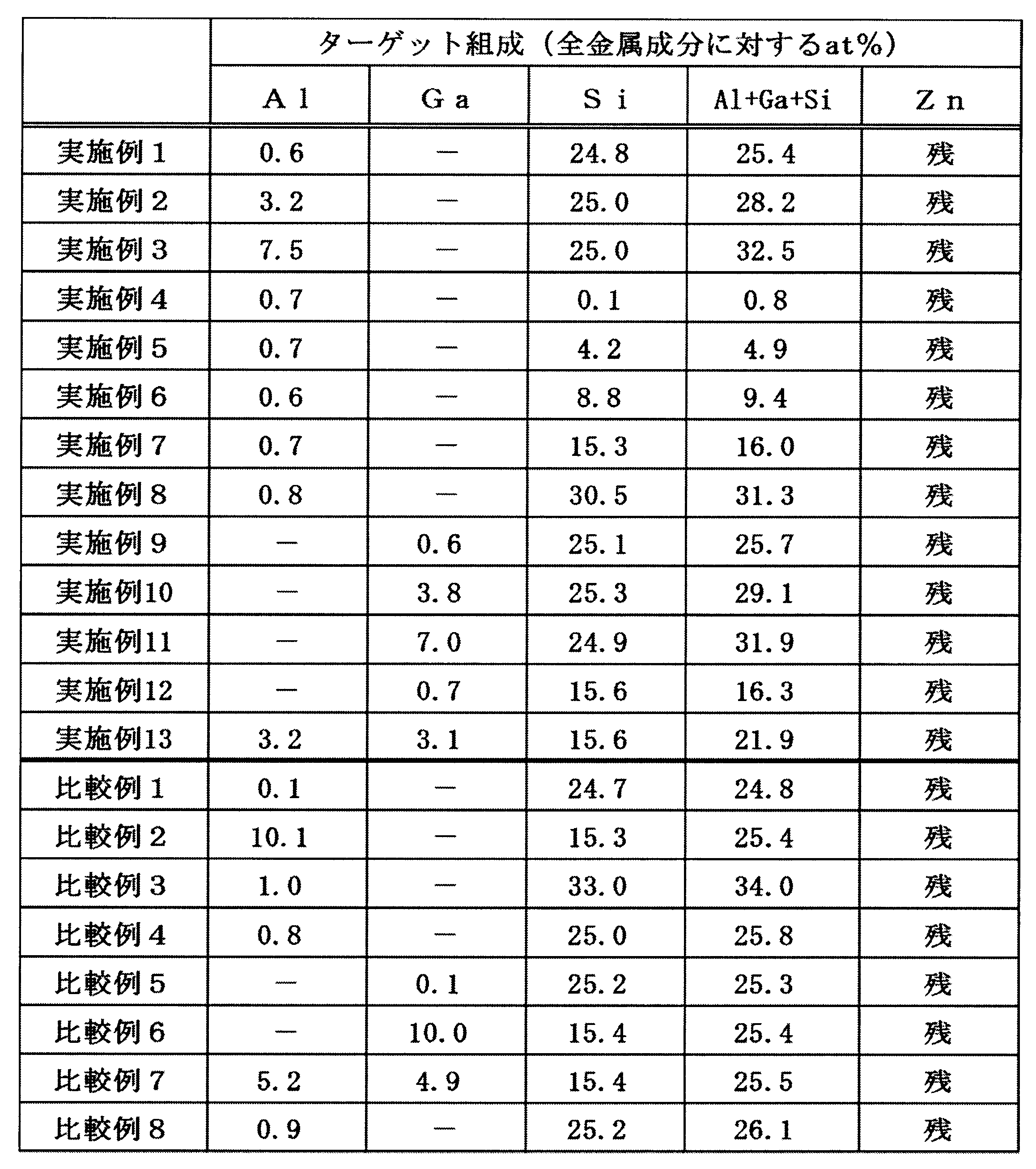
次に、表1及び表2に示された上記実施例1~13及び比較例1~8のスパッタリングターゲットについて、XRD分析、EPMAによる分析及び比抵抗測定を行った。
<XRD分析>
XRD分析は、図2に示したXRD分析の場合と同様の手法で行った。スパッタリングターゲットについてのXRD分析により、XRDピークの有無を確認した。このXRD分析は、以下の条件で行った。
試料の準備:試料はSiC-Paper(grit 180)にて湿式研磨、乾燥の後、測定試料とした。
装置:理学電気社製(RINT-Ultima/PC)
管球:Cu
管電圧:40kV
管電流:40mA
走査範囲(2θ):5°~80°
スリットサイズ:発散(DS)2/3度、散乱(SS)2/3度、受光(RS)0.8mm
測定ステップ幅:2θで0.02度
スキャンスピード:毎分2度
試料台回転スピード:30rpm
XRD分析は、図2に示したXRD分析の場合と同様の手法で行った。スパッタリングターゲットについてのXRD分析により、XRDピークの有無を確認した。このXRD分析は、以下の条件で行った。
試料の準備:試料はSiC-Paper(grit 180)にて湿式研磨、乾燥の後、測定試料とした。
装置:理学電気社製(RINT-Ultima/PC)
管球:Cu
管電圧:40kV
管電流:40mA
走査範囲(2θ):5°~80°
スリットサイズ:発散(DS)2/3度、散乱(SS)2/3度、受光(RS)0.8mm
測定ステップ幅:2θで0.02度
スキャンスピード:毎分2度
試料台回転スピード:30rpm
<EPMA分析>
スパッタリングターゲットの組織中におけるZnとSiとAlとGaとOの分布についてEPMAで得られた元素分布像から、その組織を確認した。
スパッタリングターゲットの組織中におけるZnとSiとAlとGaとOの分布についてEPMAで得られた元素分布像から、その組織を確認した。
<EBSD分析>
スパッタリングターゲットの組織中におけるZnとSiとの複合酸化物(Zn2SiO4)の粒子についてEBSDで得られたIQマップから、その大きさを確認した。なお、IQマップは95μm×33μmの断面範囲を観察し粒子サイズを定量測定した。
なお、EBSDは株式会社TSLソリューションズのOIM Data Collectionを用いてパターンを収集し、同社製OIM Analysis5.31を用いて粒子の大きさを算出した。
スパッタリングターゲットの組織中におけるZnとSiとの複合酸化物(Zn2SiO4)の粒子についてEBSDで得られたIQマップから、その大きさを確認した。なお、IQマップは95μm×33μmの断面範囲を観察し粒子サイズを定量測定した。
なお、EBSDは株式会社TSLソリューションズのOIM Data Collectionを用いてパターンを収集し、同社製OIM Analysis5.31を用いて粒子の大きさを算出した。
<比抵抗測定>
スパッタリングターゲットの比抵抗測定は、三菱化学(株)製の抵抗測定器ロレスタGPを用いて測定した。
スパッタリングターゲットの比抵抗測定は、三菱化学(株)製の抵抗測定器ロレスタGPを用いて測定した。
次に、上述した実施例1~13及び比較例1~8のスパッタリングターゲットを用いて、以下の成膜条件により、成膜試験を行った。
<成膜条件>
電源:DC1000WまたはRF1000W
全圧:0.4Pa
スパッタリングガス:Ar=45sccm、O2:5sccm
ターゲット-基板(TS)距離:70mm
<成膜条件>
電源:DC1000WまたはRF1000W
全圧:0.4Pa
スパッタリングガス:Ar=45sccm、O2:5sccm
ターゲット-基板(TS)距離:70mm
上記の成膜条件に従った成膜試験により、異常放電回数を測定した。この測定結果により、実施例1~13及び比較例1~8のスパッタリングターゲットの直流(DC)スパッタリングの可否を評価した。その測定・評価の結果を表3に示した。
<異常放電回数の測定>
上述の条件において12時間のスパッタリングを行い、異常放電の回数を計測した。その後、スパッタチャンバーを開放し、チャンバー内のパーティクルを確認した。
上述の条件において12時間のスパッタリングを行い、異常放電の回数を計測した。その後、スパッタチャンバーを開放し、チャンバー内のパーティクルを確認した。
なお、表3においては、プラズマが生じず、スパッタリング不能な場合に、「スパッタ不能」と表記した。
以上の結果を表3に示した。
以上の結果を表3に示した。
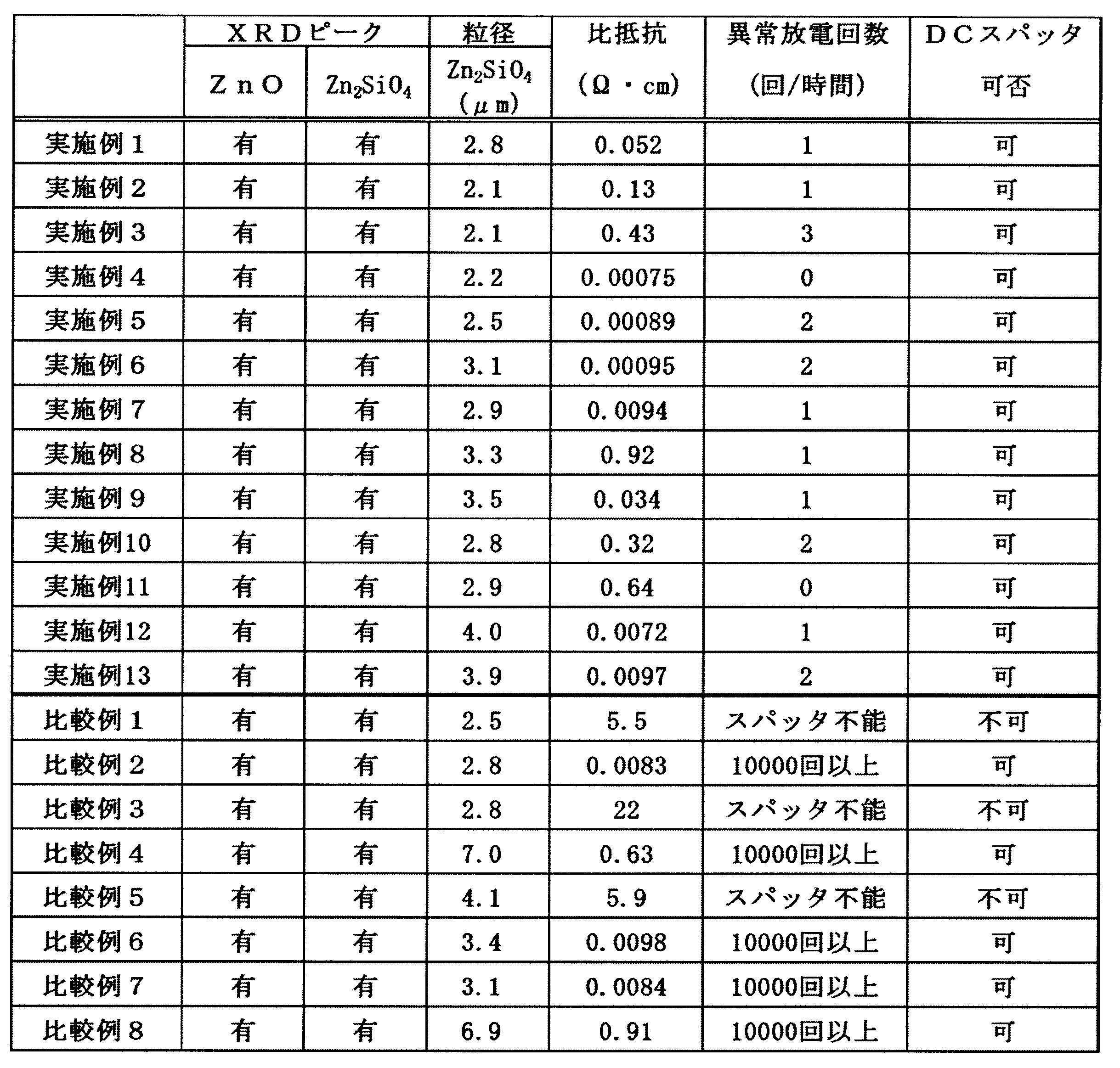
表3に示されるように、上記実施例1~13のスパッタリングターゲットのいずれにおいても、ターゲットの組織中に、上述したXRD分析及びEPMA分析では、ZnO及びZn2SiO4が形成されていることが確認できた。
表3によれば、実施例1~13のスパッタリングターゲットを使用して、直流スパッタリングを行った結果、いずれにおいても、異常放電の発生回数が極めて少ない(1時間当たり0~3回)ことが確認でき、いずれの実施例の場合にも、直流スパッタリングを行えることが実証され、パーティクル発生も確認できなかった。これに対して、比較例1、3、5のスパッタリングターゲットを直流スパッタリングで成膜しようとした場合には、プラズマが生じず、スパッタリング不能となり、或いは、比較例2、4、6、7、8の場合には、異常放電の多発(1時間当たり10000回以上)により、10秒以上の連続スパッタリングができなかった。各比較例では、高周波スパッタリングを行えば、成膜することができた。
また、比較例4の場合には、ZnO粉末とSiO2粉末の混合粉末を仮焼成するとき、その焼成温度が、低くかったため、仮焼体中に、ZnとSiとの複合酸化物が十分に形成されず、この仮焼体の粉砕粉と、ZnO粉末と、Al2O3粉末との混合粉末を焼成して焼結体を得たときに、大きなZnとSiとの複合酸化物粒子が形成されたものと考えられる。さらに、比較例8の場合には、最初から、ZnO粉末とSiO2粉末の混合粉末を焼成して焼結体を得ているため、そのときに、大きなサイズのZnとSiとの複合酸化物粒子が形成されている。
[第2実施例]
上記した第1実施例では、透明酸化物膜形成用スパッタリングターゲットを製造するにあたり、先ず、酸化亜鉛(ZnO)粉末と酸化珪素(SiO2)粉末とをモル比2:1で配合し混合した原料粉末を焼成した後に粉砕して焼成した、ZnとSiとの複合酸化物(Zn2SiO4)からなる仮焼体を作製し、この仮焼体を粉砕してZnとSiとの複合酸化物(Zn2SiO4)粉末を得る。次に、得られたZn2SiO4粉末と、ZnO粉末と、酸化アルミニウム(Al2O3)粉末及び酸化ガリウム(Ga2O3)粉末の1種又は2種との混合粉末を成形後に焼成することにより焼成体を得て、これを機械加工して、スパッタリングターゲットを製造した。
上記した第1実施例では、透明酸化物膜形成用スパッタリングターゲットを製造するにあたり、先ず、酸化亜鉛(ZnO)粉末と酸化珪素(SiO2)粉末とをモル比2:1で配合し混合した原料粉末を焼成した後に粉砕して焼成した、ZnとSiとの複合酸化物(Zn2SiO4)からなる仮焼体を作製し、この仮焼体を粉砕してZnとSiとの複合酸化物(Zn2SiO4)粉末を得る。次に、得られたZn2SiO4粉末と、ZnO粉末と、酸化アルミニウム(Al2O3)粉末及び酸化ガリウム(Ga2O3)粉末の1種又は2種との混合粉末を成形後に焼成することにより焼成体を得て、これを機械加工して、スパッタリングターゲットを製造した。
第2実施例では、上記透明酸化物膜形成用スパッタリングターゲットの製造方法において、上記の混合粉末の成形体を焼成した焼成体に係る抗折強度、熱伝導率及び相対密度に影響を与える焼成保持時間と、焼成後の冷却速度とを、表4に示されるように調整し、実施例101~127の透明酸化物膜形成用スパッタリングターゲットを作製した。実施例101~109は、Zn2SiO4粉末:50.0mol%と、Al2O3粉末:3.0mol%と、ZnO粉末:残部との混合粉末を用いた場合を、実施例110~118は、Zn2SiO4粉末:80.0mol%と、Al2O3粉末:1.0mol%と、ZnO粉末:残部との混合粉末を用いた場合を、そして、実施例119~127は、Zn2SiO4粉末:22.0mol%と、Al2O3粉末:0.6mol%と、ZnO粉末:残部との混合粉末を用いた場合を代表的に示している。
そこで、作製された実施例101~127の透明酸化物膜形成用スパッタリングターゲットについて、抗折強度、熱伝導率及び相対速度を測定した。それらの測定結果が、表4に示されている。
<抗折強度の測定>
上記で得られた焼成体から、幅:4mm、長さ:40mm、厚さ:3mmの寸法を有する板を切り出して、抗折試験片を作製した。
この試験片を用いて、JIS R-1601に規定される方法により、三点曲げ試験を行い、抗折強度(MPa)を求めた。
上記で得られた焼成体から、幅:4mm、長さ:40mm、厚さ:3mmの寸法を有する板を切り出して、抗折試験片を作製した。
この試験片を用いて、JIS R-1601に規定される方法により、三点曲げ試験を行い、抗折強度(MPa)を求めた。
<熱伝導率の測定>
上記で得られた焼成体から得た試料について、レーザーフラッシュ法により、熱伝導率(W/m・k)の測定を行った。
分析装置:NETZSCH-GeratebauGmbH製、Xeフラッシュアナライザー、試料サイズ:10mm×10mm、厚さ:2mm、測定温度:25℃、標準比較試料:SUS310、パルス幅:0.2ms、チャージレベル:270Vの条件で測定を行った。この測定では、同じ試料にて3回行い、それらの測定値の平均値を求めた。
上記で得られた焼成体から得た試料について、レーザーフラッシュ法により、熱伝導率(W/m・k)の測定を行った。
分析装置:NETZSCH-GeratebauGmbH製、Xeフラッシュアナライザー、試料サイズ:10mm×10mm、厚さ:2mm、測定温度:25℃、標準比較試料:SUS310、パルス幅:0.2ms、チャージレベル:270Vの条件で測定を行った。この測定では、同じ試料にて3回行い、それらの測定値の平均値を求めた。
<相対密度の測定>
相対密度比(%)は、焼成体を所定寸法に機械加工した後、重量を測定し、嵩密度を求めた後、理論密度ρfnで割ることで算出した。なお、理論密度ρfnについては、原料の重量に基づいて、以下に示した式により求めた。この式は、Al2O3粉末とGa2O3粉末の両方を混合した場合を示しているので、第2実施例では、Al2O3粉末のみを混合しているので、C4:Ga2O3に係る項は無いものとして求める。
相対密度比(%)は、焼成体を所定寸法に機械加工した後、重量を測定し、嵩密度を求めた後、理論密度ρfnで割ることで算出した。なお、理論密度ρfnについては、原料の重量に基づいて、以下に示した式により求めた。この式は、Al2O3粉末とGa2O3粉末の両方を混合した場合を示しているので、第2実施例では、Al2O3粉末のみを混合しているので、C4:Ga2O3に係る項は無いものとして求める。


次に、表4に示された上記実施例101~127のスパッタリングターゲットについて、XRD分析、EPMAによる分析及び比抵抗測定を行った。XRD分析、EPMAによる分析及び比抵抗測定は、第1実施例のスパッタリングターゲットについて行ったのと同様の条件で行われた。それらの結果が表5に示されている。
また、実施例101~127のスパッタリングターゲットを用いて、第1実施例と同様の成膜条件により、成膜試験を行った。
上記の成膜条件に従った成膜試験により、異常放電回数を測定した。この測定結果により、実施例101~127のスパッタリングターゲットの直流(DC)スパッタリングの可否を評価した。その測定・評価の結果を表5に示した。
また、実施例101~127のスパッタリングターゲットを用いて、第1実施例と同様の成膜条件により、成膜試験を行った。
上記の成膜条件に従った成膜試験により、異常放電回数を測定した。この測定結果により、実施例101~127のスパッタリングターゲットの直流(DC)スパッタリングの可否を評価した。その測定・評価の結果を表5に示した。
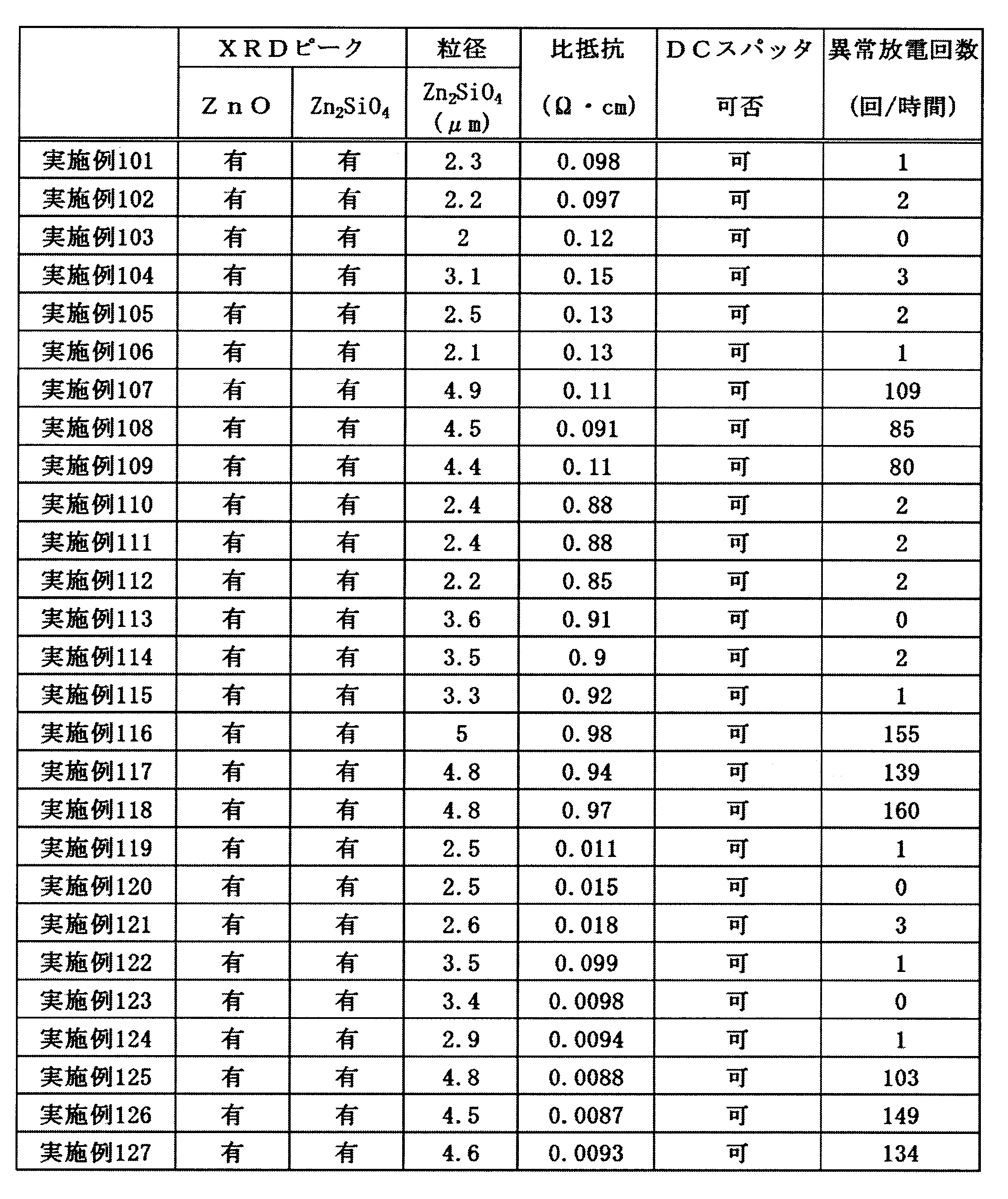
表5に示されるように、上記実施例101~127のスパッタリングターゲットのいずれにおいても、ターゲットの組織中に、上述したXRD分析及びEPMA分析では、ZnO及びZn2SiO4が形成されていることが確認でき、Zn2SiO4粒径は、5μm以下である。さらに、実施例101~127のスパッタリングターゲットを使用して、直流スパッタリングを行った結果、いずれにおいても、異常放電の発生回数が少なく、いずれの実施例の場合にも、直流スパッタリングを行えることが実証され、パーティクル発生も確認できなかった。そして、焼成保持時間と、焼成後の冷却速度を調整することにより、適切な抗折強度、熱伝導率及び相対密度を有するスパッタリングターゲットが得られることが確認され、異常放電の発生を低減でき、ターゲット割れを抑制できた。なお、Al2O3粉末の代わりに、Ga2O3粉末のみを、或いは、Al2O3粉末とGa2O3粉末の両方を混合した場合においても、上記と同様の結果が得られた。
[第3実施例]
上記第1実施例における透明酸化物膜形成用スパッタリングターゲットの製造方法では、ZnO粉末とSiO2粉末とを仮焼成したZnとSiとの複合酸化物(Zn2SiO4)を原料粉末とし、表1に示される原料組成となる混合粉末を焼成したが、第3実施例では、仮焼体の製造工程を省略しており、Zn2SiO4粉末を用いる代わりに、相当量のZnO粉末とSiO2粉末を原料粉末として使用することとした。第3実施例による透明酸化物膜形成用スパッタリングターゲットの製造方法では、SiO2粉末、Al2O3粉末及びZnO粉末を原料粉末とした。原料粉末のうち、ZnO粉末及びSiO2粉末については、表6に示される粒径のZnO粉末及びSiO2粉末を用いた。さらに、上記の焼成体に係る抗折強度、熱伝導率及び相対密度に影響を与える焼成温度と焼成保持時間とを、表6に示されるように調整し、実施例201~227の透明酸化物膜形成用スパッタリングターゲットを作製した。実施例201~209は、SiO2粉末:25.4mol%と、Al2O3粉末:1.6mol%と、ZnO粉末:残部との混合粉末を用いた場合を、実施例210~218は、SiO2粉末:30.6mol%と、Al2O3粉末:0.4mol%と、ZnO粉末:残部との混合粉末を用いた場合を、そして、実施例219~227は、SiO2粉末:15.3mol%と、Al2O3粉末:0.4mol%と、ZnO粉末:残部との混合粉末を用いた場合を代表的に示している。
上記第1実施例における透明酸化物膜形成用スパッタリングターゲットの製造方法では、ZnO粉末とSiO2粉末とを仮焼成したZnとSiとの複合酸化物(Zn2SiO4)を原料粉末とし、表1に示される原料組成となる混合粉末を焼成したが、第3実施例では、仮焼体の製造工程を省略しており、Zn2SiO4粉末を用いる代わりに、相当量のZnO粉末とSiO2粉末を原料粉末として使用することとした。第3実施例による透明酸化物膜形成用スパッタリングターゲットの製造方法では、SiO2粉末、Al2O3粉末及びZnO粉末を原料粉末とした。原料粉末のうち、ZnO粉末及びSiO2粉末については、表6に示される粒径のZnO粉末及びSiO2粉末を用いた。さらに、上記の焼成体に係る抗折強度、熱伝導率及び相対密度に影響を与える焼成温度と焼成保持時間とを、表6に示されるように調整し、実施例201~227の透明酸化物膜形成用スパッタリングターゲットを作製した。実施例201~209は、SiO2粉末:25.4mol%と、Al2O3粉末:1.6mol%と、ZnO粉末:残部との混合粉末を用いた場合を、実施例210~218は、SiO2粉末:30.6mol%と、Al2O3粉末:0.4mol%と、ZnO粉末:残部との混合粉末を用いた場合を、そして、実施例219~227は、SiO2粉末:15.3mol%と、Al2O3粉末:0.4mol%と、ZnO粉末:残部との混合粉末を用いた場合を代表的に示している。
そこで、作製された実施例201~227の透明酸化物膜形成用スパッタリングターゲットについて、上記第2実施例の場合と同様の手法で、抗折強度、熱伝導率及び相対速度を測定した。それらの測定結果が、表6に示されている。

次に、表6に示された上記実施例201~227のスパッタリングターゲットについて、XRD分析、EPMAによる分析及び比抵抗測定を行った。XRD分析、EPMAによる分析及び比抵抗測定は、第1実施例のスパッタリングターゲットについて行ったのと同様の条件で行われた。それらの結果が表7に示されている。
また、実施例201~227のスパッタリングターゲットを用いて、第1実施例と同様の成膜条件により、成膜試験を行った。
上記の成膜条件に従った成膜試験により、異常放電回数を測定した。この測定結果により、実施例201~227のスパッタリングターゲットの直流(DC)スパッタリングの可否を評価した。その測定・評価の結果を表7に示した。
また、実施例201~227のスパッタリングターゲットを用いて、第1実施例と同様の成膜条件により、成膜試験を行った。
上記の成膜条件に従った成膜試験により、異常放電回数を測定した。この測定結果により、実施例201~227のスパッタリングターゲットの直流(DC)スパッタリングの可否を評価した。その測定・評価の結果を表7に示した。

表7に示されるように、上記実施例201~227のスパッタリングターゲットのいずれにおいても、ターゲットの組織中に、上述したXRD分析及びEPMA分析では、ZnO及びZn2SiO4が形成されていることが確認でき、Zn2SiO4粒径は、5μm以下である。さらに、実施例201~227のスパッタリングターゲットを使用して、直流スパッタリングを行った結果、いずれにおいても、異常放電の発生回数が少なく、いずれの実施例の場合にも、直流スパッタリングを行えることが実証され、パーティクル発生も確認できなかった。そして、焼成温度と焼成保持時間とを調整することにより、適切な抗折強度、熱伝導率及び相対密度を有するスパッタリングターゲットが得られることが確認され、異常放電の発生を低減でき、ターゲット割れを抑制できた。なお、Al2O3粉末の代わりに、Ga2O3粉末のみを、或いは、Al2O3粉末とGa2O3粉末の両方を混合した場合においても、上記と同様の結果が得られた。
以上の様に、本発明による透明酸化物膜形成用スパッタリングターゲットの製造方法によると、ZnO粉末とSiO2粉末の混合粉末を仮焼成して、Zn2SiO4の組成を有するZnとSiとの複合酸化物を形成して仮焼体を得ておき、この仮焼体を微細な粉砕粉とした後に、この粉砕粉を原料粉末とし、これと、ZnO粉末と、Al2O3粉末及びGa2O3粉末の1種又は2種とを混合した混合粉末を焼成することにより焼成体を得るようにしたので、その焼成体中には、微細なZnとSiとの複合酸化物(Zn2SiO4)が存在していることが確認され、そして、そのスパッタリングターゲットでは、比抵抗も低減することができて、直流(DC)スパッタリングを可能とすることができた。さらに、適切な抗折強度、熱伝導率及び相対密度を有するスパッタリングターゲットが得られるので、異常放電の発生を低減でき、ターゲット割れを抑制できた。
スパッタリングターゲット中におけるZnとSiとの複合酸化物の生成を調整することにより、透明酸化物膜を直流スパッタリングで成膜することが可能となる。また、スパッタリング時に、異常放電が発生しにくい酸化亜鉛系の透明酸化物膜形成用スパッタリングターゲット及びその製造方法を提供することができる。
Claims (7)
- 全金属成分量に対して、Al及びGaのいずれか1種又は2種:0.6~8.0at%と、Si:0.1at%以上とを、AlとGaとSiとの合計で33.0at%以下含有し、残部がZnおよび不可避不純物からなる組成の焼成体であり、
前記焼成体中において、ZnとSiとの複合酸化物の粒径が5μm以下であることを特徴とする透明酸化物膜形成用スパッタリングターゲット。 - 前記焼成体の抗折強度が、90MPa以上であることを特徴とする請求項1に記載の透明酸化物膜形成用スパッタリングターゲット。
- 前記焼成体の相対密度が、90%以上であることを特徴とする請求項1に記載の透明酸化物膜形成用スパッタリングターゲット。
- 前記焼成体の熱伝導率が、7.5W/m・k以上であることを特徴とする請求項1に記載の透明酸化物膜形成用スパッタリングターゲット。
- 請求項1乃至4のいずれかに記載の透明酸化物膜形成用スパッタリングターゲットの製造方法であって、
ZnO粉末とSiO2粉末とをモル比2:1で配合し混合した原料粉末を焼成した後に粉砕して複合酸化物粉末とし、
前記複合酸化物粉末とAl2O3粉末及びGa2O3粉末のいずれか1種又は2種と、ZnO粉末とを配合し混合して得られた混合粉末を焼成して焼成体を得ることを特徴とする透明酸化物膜形成用スパッタリングターゲットの製造方法。 - 前記混合粉末は、1100~1450℃の温度、非酸化性雰囲気で、1~10時間を保持して焼成され、
前記焼成体は、冷却速度:30~150℃/hで冷却されることを特徴とする請求項5に記載の透明酸化物膜形成用スパッタリングターゲットの製造方法。 - 請求項1乃至4のいずれかに記載の透明酸化物膜形成用スパッタリングターゲットの製造方法であって、
平均粒径:0.1~3.0μmのZnO粉末と、平均粒径:0.2~4.0μmのSiO2粉末とAl2O3粉末及びGa2O3粉末のいずれか1種又は2種とを配合し混合し、1150~1300℃の温度、100~400kgf/cm2の圧力、非酸化性雰囲気で、1~10時間を保持して加圧焼成して焼成体を得ることを特徴とする透明酸化物膜形成用スパッタリングターゲットの製造方法。
Priority Applications (2)
| Application Number | Priority Date | Filing Date | Title |
|---|---|---|---|
| CN201380041837.4A CN104540976B (zh) | 2012-08-10 | 2013-08-09 | 透明氧化物膜形成用溅射靶及其制造方法 |
| KR1020157001661A KR101990663B1 (ko) | 2012-08-10 | 2013-08-09 | 투명 산화물막 형성용 스퍼터링 타깃 및 그 제조 방법 |
Applications Claiming Priority (4)
| Application Number | Priority Date | Filing Date | Title |
|---|---|---|---|
| JP2012178802 | 2012-08-10 | ||
| JP2012-178802 | 2012-08-10 | ||
| JP2013150310A JP6278229B2 (ja) | 2012-08-10 | 2013-07-19 | 透明酸化物膜形成用スパッタリングターゲット及びその製造方法 |
| JP2013-150310 | 2013-07-19 |
Publications (1)
| Publication Number | Publication Date |
|---|---|
| WO2014025017A1 true WO2014025017A1 (ja) | 2014-02-13 |
Family
ID=50068234
Family Applications (1)
| Application Number | Title | Priority Date | Filing Date |
|---|---|---|---|
| PCT/JP2013/071670 Ceased WO2014025017A1 (ja) | 2012-08-10 | 2013-08-09 | 透明酸化物膜形成用スパッタリングターゲット及びその製造方法 |
Country Status (5)
| Country | Link |
|---|---|
| JP (1) | JP6278229B2 (ja) |
| KR (1) | KR101990663B1 (ja) |
| CN (1) | CN104540976B (ja) |
| TW (1) | TWI561650B (ja) |
| WO (1) | WO2014025017A1 (ja) |
Cited By (1)
| Publication number | Priority date | Publication date | Assignee | Title |
|---|---|---|---|---|
| WO2016136855A1 (ja) * | 2015-02-27 | 2016-09-01 | Jx金属株式会社 | 酸化物焼結体、酸化物スパッタリングターゲット及び酸化物薄膜 |
Families Citing this family (7)
| Publication number | Priority date | Publication date | Assignee | Title |
|---|---|---|---|---|
| KR102281399B1 (ko) | 2013-12-26 | 2021-07-23 | 고쿠리츠다이가쿠호진 토쿄고교 다이가꾸 | 금속 산화물의 박막, 그 박막을 구비한 유기 일렉트로 루미네선스 소자, 태양전지, 및 유기 태양전지 |
| JP6677058B2 (ja) * | 2016-03-04 | 2020-04-08 | 住友金属鉱山株式会社 | Sn−Zn−O系酸化物焼結体とその製造方法 |
| CN107523794A (zh) * | 2017-09-07 | 2017-12-29 | 于盟盟 | 一种用于溅射透明导电薄膜的靶材 |
| CN110352263A (zh) * | 2018-02-08 | 2019-10-18 | 三菱综合材料株式会社 | 氧化物溅射靶及氧化物溅射靶的制造方法 |
| WO2019163811A1 (ja) * | 2018-02-22 | 2019-08-29 | 三菱マテリアル株式会社 | 酸化物膜、酸化物膜の製造方法、及び、窒素含有酸化物スパッタリングターゲット |
| WO2019187269A1 (ja) * | 2018-03-30 | 2019-10-03 | 三井金属鉱業株式会社 | 酸化物焼結体、スパッタリングターゲットおよび透明導電膜 |
| KR20220087425A (ko) | 2019-10-23 | 2022-06-24 | 미쓰비시 마테리알 가부시키가이샤 | 산화물 스퍼터링 타깃 |
Citations (4)
| Publication number | Priority date | Publication date | Assignee | Title |
|---|---|---|---|---|
| JPH11236219A (ja) * | 1998-02-20 | 1999-08-31 | Sumitomo Metal Mining Co Ltd | ZnO系焼結体およびその製法 |
| JPH11256320A (ja) * | 1998-03-13 | 1999-09-21 | Sumitomo Metal Mining Co Ltd | ZnO系焼結体 |
| JP2001131736A (ja) * | 1999-11-09 | 2001-05-15 | Nikko Materials Co Ltd | スパッタリングターゲット及びその製造方法 |
| JP2011179056A (ja) * | 2010-02-26 | 2011-09-15 | Taiheiyo Cement Corp | スパッタリングターゲット |
Family Cites Families (14)
| Publication number | Priority date | Publication date | Assignee | Title |
|---|---|---|---|---|
| JP4067141B2 (ja) * | 1994-08-17 | 2008-03-26 | Agcセラミックス株式会社 | 透明導電膜とその製造方法およびスパッタリングターゲット |
| WO2001013371A1 (en) * | 1999-01-12 | 2001-02-22 | Nikko Materials Company, Limited | Light-transmitting film and sputtering target for forming the light-transmitting film |
| JP3841388B2 (ja) * | 1998-02-16 | 2006-11-01 | 日鉱金属株式会社 | 光ディスク用保護膜及び光ディスクの保護膜形成用スパッタリングターゲット |
| JP3890362B2 (ja) * | 2004-06-17 | 2007-03-07 | 国立大学法人室蘭工業大学 | 表面プラズモン共鳴現象測定装置 |
| JP4828529B2 (ja) * | 2005-05-30 | 2011-11-30 | Jx日鉱日石金属株式会社 | スパッタリングターゲット及びその製造方法 |
| JP4788463B2 (ja) | 2006-04-25 | 2011-10-05 | 住友金属鉱山株式会社 | 酸化物焼結体、透明酸化物膜、ガスバリア性透明樹脂基板、ガスバリア性透明導電性樹脂基板およびフレキシブル表示素子 |
| JP5358891B2 (ja) * | 2006-08-11 | 2013-12-04 | 日立金属株式会社 | 酸化亜鉛焼結体の製造方法 |
| WO2009145152A1 (ja) * | 2008-05-27 | 2009-12-03 | 株式会社カネカ | 透明導電膜およびその製造方法 |
| JP5727130B2 (ja) * | 2008-08-18 | 2015-06-03 | 東ソー株式会社 | 複合酸化物焼結体及びその用途 |
| JP5582279B2 (ja) * | 2008-10-22 | 2014-09-03 | 戸田工業株式会社 | Ni−Zn−Cu系フェライト焼結体からなるインダクタンス素子 |
| JP2010202451A (ja) * | 2009-03-03 | 2010-09-16 | Sumitomo Electric Ind Ltd | In−Ga−Zn系複合酸化物焼結体の製造方法 |
| JP5596963B2 (ja) * | 2009-11-19 | 2014-09-24 | 出光興産株式会社 | スパッタリングターゲット及びそれを用いた薄膜トランジスタ |
| JP2012144410A (ja) * | 2011-01-14 | 2012-08-02 | Kobelco Kaken:Kk | 酸化物焼結体およびスパッタリングターゲット |
| JP2012102403A (ja) * | 2011-12-15 | 2012-05-31 | Kanazawa Inst Of Technology | 酸化亜鉛系透明導電膜、マグネトロンスパッタリング用焼結体ターゲット、液晶ディスプレイ及びタッチパネル、ならびに酸化亜鉛系透明導電膜を含んでなる機器 |
-
2013
- 2013-07-19 JP JP2013150310A patent/JP6278229B2/ja not_active Expired - Fee Related
- 2013-08-09 TW TW102128640A patent/TWI561650B/zh not_active IP Right Cessation
- 2013-08-09 KR KR1020157001661A patent/KR101990663B1/ko not_active Expired - Fee Related
- 2013-08-09 WO PCT/JP2013/071670 patent/WO2014025017A1/ja not_active Ceased
- 2013-08-09 CN CN201380041837.4A patent/CN104540976B/zh not_active Expired - Fee Related
Patent Citations (4)
| Publication number | Priority date | Publication date | Assignee | Title |
|---|---|---|---|---|
| JPH11236219A (ja) * | 1998-02-20 | 1999-08-31 | Sumitomo Metal Mining Co Ltd | ZnO系焼結体およびその製法 |
| JPH11256320A (ja) * | 1998-03-13 | 1999-09-21 | Sumitomo Metal Mining Co Ltd | ZnO系焼結体 |
| JP2001131736A (ja) * | 1999-11-09 | 2001-05-15 | Nikko Materials Co Ltd | スパッタリングターゲット及びその製造方法 |
| JP2011179056A (ja) * | 2010-02-26 | 2011-09-15 | Taiheiyo Cement Corp | スパッタリングターゲット |
Cited By (3)
| Publication number | Priority date | Publication date | Assignee | Title |
|---|---|---|---|---|
| WO2016136855A1 (ja) * | 2015-02-27 | 2016-09-01 | Jx金属株式会社 | 酸化物焼結体、酸化物スパッタリングターゲット及び酸化物薄膜 |
| JP6023920B1 (ja) * | 2015-02-27 | 2016-11-09 | Jx金属株式会社 | 酸化物焼結体、酸化物スパッタリングターゲット及び酸化物薄膜 |
| US10227261B2 (en) | 2015-02-27 | 2019-03-12 | Jx Nippon Mining & Metals Corporation | Oxide sintered compact, oxide sputtering target, and oxide thin film |
Also Published As
| Publication number | Publication date |
|---|---|
| TW201413014A (zh) | 2014-04-01 |
| CN104540976A (zh) | 2015-04-22 |
| JP6278229B2 (ja) | 2018-02-14 |
| TWI561650B (en) | 2016-12-11 |
| KR20150040273A (ko) | 2015-04-14 |
| CN104540976B (zh) | 2017-02-22 |
| JP2014055348A (ja) | 2014-03-27 |
| KR101990663B1 (ko) | 2019-06-19 |
Similar Documents
| Publication | Publication Date | Title |
|---|---|---|
| JP6278229B2 (ja) | 透明酸化物膜形成用スパッタリングターゲット及びその製造方法 | |
| EP2301904B1 (en) | Sintered complex oxide, method for producing sintered complex oxide, sputtering target and method for producing thin film | |
| KR101738742B1 (ko) | 산화물 소결체, 스퍼터링 타깃 및 박막 그리고 산화물 소결체의 제조 방법 | |
| JP2012052227A (ja) | スパッタリングターゲットの製造方法およびスパッタリングターゲット | |
| JP5550768B1 (ja) | 焼結体及びアモルファス膜 | |
| EP3210952B1 (en) | Oxide sintered compact, oxide sputtering target, and oxide thin film | |
| JP7086080B2 (ja) | 酸化物焼結体およびスパッタリングターゲット | |
| JP5690982B1 (ja) | 焼結体及びアモルファス膜 | |
| TW201405580A (zh) | 燒結體及非晶膜 | |
| JP5954620B2 (ja) | 透明酸化物膜形成用スパッタリングターゲット及びその製造方法 | |
| JP5800209B2 (ja) | 酸化物スパッタリングターゲットおよびその製造方法 | |
| JP2012224903A (ja) | 酸化物スパッタリングターゲットおよびその製造方法 | |
| KR101945083B1 (ko) | 소결체 및 그 소결체로 이루어지는 스퍼터링 타깃 그리고 그 스퍼터링 타깃을 사용하여 형성한 박막 | |
| JP7726991B2 (ja) | スパッタリングターゲット及びその製造方法 | |
| KR102095828B1 (ko) | 산화물 소결체 및 스퍼터링 타깃 | |
| JP2012162755A (ja) | 酸化物スパッタリングターゲットおよびその製造方法 |
Legal Events
| Date | Code | Title | Description |
|---|---|---|---|
| 121 | Ep: the epo has been informed by wipo that ep was designated in this application |
Ref document number: 13827513 Country of ref document: EP Kind code of ref document: A1 |
|
| ENP | Entry into the national phase |
Ref document number: 20157001661 Country of ref document: KR Kind code of ref document: A |
|
| NENP | Non-entry into the national phase |
Ref country code: DE |
|
| 122 | Ep: pct application non-entry in european phase |
Ref document number: 13827513 Country of ref document: EP Kind code of ref document: A1 |