WO2014024802A1 - 蓄電装置の製造方法、超音波溶接用の補助板及び蓄電装置 - Google Patents
蓄電装置の製造方法、超音波溶接用の補助板及び蓄電装置 Download PDFInfo
- Publication number
- WO2014024802A1 WO2014024802A1 PCT/JP2013/071036 JP2013071036W WO2014024802A1 WO 2014024802 A1 WO2014024802 A1 WO 2014024802A1 JP 2013071036 W JP2013071036 W JP 2013071036W WO 2014024802 A1 WO2014024802 A1 WO 2014024802A1
- Authority
- WO
- WIPO (PCT)
- Prior art keywords
- metal member
- auxiliary plate
- metal
- storage device
- buffer
- Prior art date
- Legal status (The legal status is an assumption and is not a legal conclusion. Google has not performed a legal analysis and makes no representation as to the accuracy of the status listed.)
- Ceased
Links
Images








Classifications
-
- B—PERFORMING OPERATIONS; TRANSPORTING
- B23—MACHINE TOOLS; METAL-WORKING NOT OTHERWISE PROVIDED FOR
- B23K—SOLDERING OR UNSOLDERING; WELDING; CLADDING OR PLATING BY SOLDERING OR WELDING; CUTTING BY APPLYING HEAT LOCALLY, e.g. FLAME CUTTING; WORKING BY LASER BEAM
- B23K20/00—Non-electric welding by applying impact or other pressure, with or without the application of heat, e.g. cladding or plating
- B23K20/002—Non-electric welding by applying impact or other pressure, with or without the application of heat, e.g. cladding or plating specially adapted for particular articles or work
-
- B—PERFORMING OPERATIONS; TRANSPORTING
- B23—MACHINE TOOLS; METAL-WORKING NOT OTHERWISE PROVIDED FOR
- B23K—SOLDERING OR UNSOLDERING; WELDING; CLADDING OR PLATING BY SOLDERING OR WELDING; CUTTING BY APPLYING HEAT LOCALLY, e.g. FLAME CUTTING; WORKING BY LASER BEAM
- B23K20/00—Non-electric welding by applying impact or other pressure, with or without the application of heat, e.g. cladding or plating
- B23K20/10—Non-electric welding by applying impact or other pressure, with or without the application of heat, e.g. cladding or plating making use of vibrations, e.g. ultrasonic welding
-
- B—PERFORMING OPERATIONS; TRANSPORTING
- B23—MACHINE TOOLS; METAL-WORKING NOT OTHERWISE PROVIDED FOR
- B23K—SOLDERING OR UNSOLDERING; WELDING; CLADDING OR PLATING BY SOLDERING OR WELDING; CUTTING BY APPLYING HEAT LOCALLY, e.g. FLAME CUTTING; WORKING BY LASER BEAM
- B23K20/00—Non-electric welding by applying impact or other pressure, with or without the application of heat, e.g. cladding or plating
- B23K20/10—Non-electric welding by applying impact or other pressure, with or without the application of heat, e.g. cladding or plating making use of vibrations, e.g. ultrasonic welding
- B23K20/106—Features related to sonotrodes
-
- B—PERFORMING OPERATIONS; TRANSPORTING
- B23—MACHINE TOOLS; METAL-WORKING NOT OTHERWISE PROVIDED FOR
- B23K—SOLDERING OR UNSOLDERING; WELDING; CLADDING OR PLATING BY SOLDERING OR WELDING; CUTTING BY APPLYING HEAT LOCALLY, e.g. FLAME CUTTING; WORKING BY LASER BEAM
- B23K20/00—Non-electric welding by applying impact or other pressure, with or without the application of heat, e.g. cladding or plating
- B23K20/24—Preliminary treatment
-
- H—ELECTRICITY
- H01—ELECTRIC ELEMENTS
- H01M—PROCESSES OR MEANS, e.g. BATTERIES, FOR THE DIRECT CONVERSION OF CHEMICAL ENERGY INTO ELECTRICAL ENERGY
- H01M10/00—Secondary cells; Manufacture thereof
- H01M10/04—Construction or manufacture in general
- H01M10/0404—Machines for assembling batteries
-
- H—ELECTRICITY
- H01—ELECTRIC ELEMENTS
- H01M—PROCESSES OR MEANS, e.g. BATTERIES, FOR THE DIRECT CONVERSION OF CHEMICAL ENERGY INTO ELECTRICAL ENERGY
- H01M10/00—Secondary cells; Manufacture thereof
- H01M10/04—Construction or manufacture in general
- H01M10/0431—Cells with wound or folded electrodes
-
- B—PERFORMING OPERATIONS; TRANSPORTING
- B23—MACHINE TOOLS; METAL-WORKING NOT OTHERWISE PROVIDED FOR
- B23K—SOLDERING OR UNSOLDERING; WELDING; CLADDING OR PLATING BY SOLDERING OR WELDING; CUTTING BY APPLYING HEAT LOCALLY, e.g. FLAME CUTTING; WORKING BY LASER BEAM
- B23K2101/00—Articles made by soldering, welding or cutting
- B23K2101/36—Electric or electronic devices
- B23K2101/38—Conductors
-
- B—PERFORMING OPERATIONS; TRANSPORTING
- B23—MACHINE TOOLS; METAL-WORKING NOT OTHERWISE PROVIDED FOR
- B23K—SOLDERING OR UNSOLDERING; WELDING; CLADDING OR PLATING BY SOLDERING OR WELDING; CUTTING BY APPLYING HEAT LOCALLY, e.g. FLAME CUTTING; WORKING BY LASER BEAM
- B23K2103/00—Materials to be soldered, welded or cut
- B23K2103/08—Non-ferrous metals or alloys
- B23K2103/10—Aluminium or alloys thereof
-
- B—PERFORMING OPERATIONS; TRANSPORTING
- B23—MACHINE TOOLS; METAL-WORKING NOT OTHERWISE PROVIDED FOR
- B23K—SOLDERING OR UNSOLDERING; WELDING; CLADDING OR PLATING BY SOLDERING OR WELDING; CUTTING BY APPLYING HEAT LOCALLY, e.g. FLAME CUTTING; WORKING BY LASER BEAM
- B23K2103/00—Materials to be soldered, welded or cut
- B23K2103/08—Non-ferrous metals or alloys
- B23K2103/12—Copper or alloys thereof
-
- B—PERFORMING OPERATIONS; TRANSPORTING
- B23—MACHINE TOOLS; METAL-WORKING NOT OTHERWISE PROVIDED FOR
- B23K—SOLDERING OR UNSOLDERING; WELDING; CLADDING OR PLATING BY SOLDERING OR WELDING; CUTTING BY APPLYING HEAT LOCALLY, e.g. FLAME CUTTING; WORKING BY LASER BEAM
- B23K2103/00—Materials to be soldered, welded or cut
- B23K2103/18—Dissimilar materials
-
- H—ELECTRICITY
- H01—ELECTRIC ELEMENTS
- H01M—PROCESSES OR MEANS, e.g. BATTERIES, FOR THE DIRECT CONVERSION OF CHEMICAL ENERGY INTO ELECTRICAL ENERGY
- H01M10/00—Secondary cells; Manufacture thereof
- H01M10/04—Construction or manufacture in general
- H01M10/0404—Machines for assembling batteries
- H01M10/0409—Machines for assembling batteries for cells with wound electrodes
-
- H—ELECTRICITY
- H01—ELECTRIC ELEMENTS
- H01M—PROCESSES OR MEANS, e.g. BATTERIES, FOR THE DIRECT CONVERSION OF CHEMICAL ENERGY INTO ELECTRICAL ENERGY
- H01M50/00—Constructional details or processes of manufacture of the non-active parts of electrochemical cells other than fuel cells, e.g. hybrid cells
- H01M50/10—Primary casings; Jackets or wrappings
- H01M50/102—Primary casings; Jackets or wrappings characterised by their shape or physical structure
- H01M50/103—Primary casings; Jackets or wrappings characterised by their shape or physical structure prismatic or rectangular
-
- H—ELECTRICITY
- H01—ELECTRIC ELEMENTS
- H01M—PROCESSES OR MEANS, e.g. BATTERIES, FOR THE DIRECT CONVERSION OF CHEMICAL ENERGY INTO ELECTRICAL ENERGY
- H01M50/00—Constructional details or processes of manufacture of the non-active parts of electrochemical cells other than fuel cells, e.g. hybrid cells
- H01M50/10—Primary casings; Jackets or wrappings
- H01M50/147—Lids or covers
-
- H—ELECTRICITY
- H01—ELECTRIC ELEMENTS
- H01M—PROCESSES OR MEANS, e.g. BATTERIES, FOR THE DIRECT CONVERSION OF CHEMICAL ENERGY INTO ELECTRICAL ENERGY
- H01M50/00—Constructional details or processes of manufacture of the non-active parts of electrochemical cells other than fuel cells, e.g. hybrid cells
- H01M50/50—Current conducting connections for cells or batteries
- H01M50/528—Fixed electrical connections, i.e. not intended for disconnection
-
- H—ELECTRICITY
- H01—ELECTRIC ELEMENTS
- H01M—PROCESSES OR MEANS, e.g. BATTERIES, FOR THE DIRECT CONVERSION OF CHEMICAL ENERGY INTO ELECTRICAL ENERGY
- H01M50/00—Constructional details or processes of manufacture of the non-active parts of electrochemical cells other than fuel cells, e.g. hybrid cells
- H01M50/50—Current conducting connections for cells or batteries
- H01M50/531—Electrode connections inside a battery casing
- H01M50/538—Connection of several leads or tabs of wound or folded electrode stacks
-
- H—ELECTRICITY
- H01—ELECTRIC ELEMENTS
- H01M—PROCESSES OR MEANS, e.g. BATTERIES, FOR THE DIRECT CONVERSION OF CHEMICAL ENERGY INTO ELECTRICAL ENERGY
- H01M50/00—Constructional details or processes of manufacture of the non-active parts of electrochemical cells other than fuel cells, e.g. hybrid cells
- H01M50/50—Current conducting connections for cells or batteries
- H01M50/543—Terminals
- H01M50/552—Terminals characterised by their shape
- H01M50/561—Hollow metallic terminals, e.g. terminal bushings
-
- Y—GENERAL TAGGING OF NEW TECHNOLOGICAL DEVELOPMENTS; GENERAL TAGGING OF CROSS-SECTIONAL TECHNOLOGIES SPANNING OVER SEVERAL SECTIONS OF THE IPC; TECHNICAL SUBJECTS COVERED BY FORMER USPC CROSS-REFERENCE ART COLLECTIONS [XRACs] AND DIGESTS
- Y02—TECHNOLOGIES OR APPLICATIONS FOR MITIGATION OR ADAPTATION AGAINST CLIMATE CHANGE
- Y02E—REDUCTION OF GREENHOUSE GAS [GHG] EMISSIONS, RELATED TO ENERGY GENERATION, TRANSMISSION OR DISTRIBUTION
- Y02E60/00—Enabling technologies; Technologies with a potential or indirect contribution to GHG emissions mitigation
- Y02E60/10—Energy storage using batteries
-
- Y—GENERAL TAGGING OF NEW TECHNOLOGICAL DEVELOPMENTS; GENERAL TAGGING OF CROSS-SECTIONAL TECHNOLOGIES SPANNING OVER SEVERAL SECTIONS OF THE IPC; TECHNICAL SUBJECTS COVERED BY FORMER USPC CROSS-REFERENCE ART COLLECTIONS [XRACs] AND DIGESTS
- Y02—TECHNOLOGIES OR APPLICATIONS FOR MITIGATION OR ADAPTATION AGAINST CLIMATE CHANGE
- Y02P—CLIMATE CHANGE MITIGATION TECHNOLOGIES IN THE PRODUCTION OR PROCESSING OF GOODS
- Y02P70/00—Climate change mitigation technologies in the production process for final industrial or consumer products
- Y02P70/50—Manufacturing or production processes characterised by the final manufactured product
Definitions
- the present invention provides ultrasonic waves from a first metal member side to a plurality of operating positions in a state where a metal foil extending from an electrode plate constituting an electrode body is sandwiched between a first metal member and a second metal member.
- the present invention relates to a method for manufacturing a power storage device that is bonded by applying vibration, an auxiliary plate for ultrasonic welding used in the manufacturing process, and a power storage device using the auxiliary plate.
- a power storage element of a power storage device is composed of electrode plates stacked in layers in order to improve power storage efficiency.
- the metal foil extending from each electrode plate is often bundled and directly or indirectly joined to the wiring member.
- ultrasonic welding technology is widely used as the joining technology for the metal foil.
- the metal foil is not simply welded by applying ultrasonic vibration. Specifically, it is as follows. As described in the following Patent Document 1, while sandwiching a metal member (first metal member) between a member (so-called horn tip) that causes ultrasonic vibration to act on the metal foil and the metal foil, A metal member (second metal member) is also disposed on the opposite surface of the bundled metal foil. In this way, the bundled metal foil is sandwiched between the first metal member and the second metal member, and the first metal member is bonded by applying ultrasonic vibration to the first metal member. The metal foil is protected.
- a joining area is secured while avoiding an increase in the size of the tip of the horn.
- the metal member for protecting the metal foil may be damaged.
- the first metal member when ultrasonic vibration is applied to the first metal member, the first metal member is deformed so as to swell around each position where the ultrasonic vibration is applied, and adjacent to each other. The deformation from both sides overlaps between the positions where ultrasonic vibrations are applied.
- the present invention has been made in view of such circumstances, and its purpose is to allow damage to the metal member even when ultrasonic welding is performed at a plurality of locations while protecting the metal foil to be welded with the metal member. It is in the point to prevent.
- a method for manufacturing a power storage device includes: A step of sandwiching the metal foil extending from the electrode plates stacked in layers between the first metal member provided with the buffer portion and the second metal member; Joining the metal foil, the first metal member, and the second metal member by applying ultrasonic vibration to a plurality of operating positions from the first metal member side, In the joining step, each action position is set so that the buffer portion is located between the action positions of adjacent ultrasonic vibrations,
- the buffer portion includes a cutout portion in which a part of the first metal member is cut out, a thick portion in which the plate thickness of the first metal member is partially increased, and a part of the first metal member is projected. At least one of the ridges bent into a shape is provided.
- the buffer part has a notch
- the cutout portion may extend from the edge of the first metal member.
- the buffer part has a thick part, In the first metal member, the thickness of the boundary portion between the thick portion and the surrounding thin portion may gradually change.
- the buffer part has a ridge part,
- the ridge portion may extend in a direction intersecting with a line connecting the operation positions of adjacent ultrasonic vibrations.
- Edges of the first metal member and the second metal member are connected to each other at the connecting portion,
- the cutout portion may be formed by cutting out a range from the edge of the first metal member to at least the connection portion.
- Edges of the first metal member and the second metal member are connected to each other at the connecting portion, In the sandwiching step, the metal foil may be sandwiched between the first metal member and the second metal member so that the edge of the metal foil is in contact with the connecting portion.
- the buffer portion may extend within a range from the edge of the first metal member to the boundary position with the connecting portion of the first metal member.
- the buffer portion may extend so as to surround a part of the operation position.
- the auxiliary plate for ultrasonic welding Ultrasound composed of a metal member having a contact surface to be applied to a welding surface of a foil-like welding object and a working surface that is a surface on which ultrasonic vibration is applied and is opposite to the contact surface
- An auxiliary plate for welding At least one of a notch part in which a part of the metal member is cut out, a thick part in which the plate thickness of the metal member is partially increased, and a protrusion part in which a part of the metal member is bent into a protrusion shape
- the buffer part which has is provided.
- the buffer part has a notch
- the cutout portion may extend from the edge of the metal member.
- the buffer part has a thick part, In the metal member, the thickness of the boundary portion between the thick portion and the surrounding thin portion may gradually change.
- the buffer portion may extend so as to surround a part of the operation position.
- the power storage device includes: Any one of the above-mentioned, which has a plurality of electrode bodies configured by laminating an electrode plate with a metal foil extending on one end side, and an action position on which ultrasonic vibration is applied, and is applied to the metal foil
- An auxiliary plate for ultrasonic welding of In the auxiliary plate, the buffer portion is formed between the adjacent operation positions.
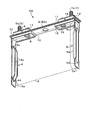
- FIG. 1 is an external perspective view of the power storage device according to the first embodiment of the present invention.
- FIG. 2 is a perspective view showing an internal configuration of the power storage device according to the first embodiment of the present invention.
- FIG. 3 is a cross-sectional view of a main part of the power storage device according to the first embodiment of the present invention.
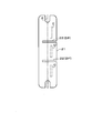
- FIG. 4 is an enlarged view of a state in which the auxiliary plate for ultrasonic welding according to the first embodiment of the present invention is developed.
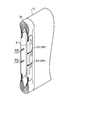
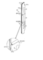
- FIG. 5 is an enlarged perspective view of the auxiliary plate for ultrasonic welding according to the first embodiment of the present invention.
- FIG. 6 is a cross-sectional view showing an ultrasonic welding operation according to the first embodiment of the present invention.
- FIG. 7 is a perspective view showing an assembly operation of the electricity storage element according to the first embodiment of the present invention, and is a perspective view before attaching an auxiliary plate.
- FIG. 8 is a perspective view showing an assembly operation of the electricity storage element according to the first embodiment of the present invention, and is a perspective view with an auxiliary plate attached.
- FIG. 9 is a perspective view showing an assembly operation of the electricity storage element according to the first embodiment of the present invention, and is a perspective view in a state where a current collector is attached.
- FIG. 10 is an enlarged view of a state in which the auxiliary plate for ultrasonic welding according to the second embodiment of the present invention is developed.
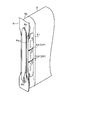
- FIG. 11 is an enlarged perspective view and a partially enlarged view of the auxiliary plate for ultrasonic welding according to the second embodiment of the present invention.
- FIG. 12 is an enlarged view of a developed state of the auxiliary plate for ultrasonic welding according to the third embodiment of the present invention.
- FIG. 13 is an enlarged perspective view and a partially enlarged perspective view of an auxiliary plate for ultrasonic welding according to a third embodiment of the present invention.
- FIG. 14 is a cross-sectional view showing an ultrasonic welding operation according to the third embodiment of the present invention.
- FIG. 15 is a cross-sectional view showing an ultrasonic welding operation according to another embodiment of the present invention.
- FIG. 16 is a cross-sectional view showing an ultrasonic welding operation according to another embodiment of the present invention.
- FIG. 17 is an enlarged view of a state in which an auxiliary plate for ultrasonic welding according to another embodiment of the present invention is developed.
- FIG. 18 is an enlarged perspective view of an auxiliary plate for ultras
- a method for manufacturing a power storage device includes: A step of sandwiching the metal foil extending from the electrode plates stacked in layers between the first metal member provided with the buffer portion and the second metal member; Joining the metal foil, the first metal member, and the second metal member by applying ultrasonic vibration to a plurality of operating positions from the first metal member side, In the joining step, each action position is set so that the buffer portion is located between the action positions of adjacent ultrasonic vibrations,
- the buffer portion includes a cutout portion in which a part of the first metal member is cut out, a thick portion in which the plate thickness of the first metal member is partially increased, and a part of the first metal member is projected. At least one of the ridges bent into a shape is provided.
- the buffer portion is formed in the metal member (the first metal member) for protecting the metal foil to be welded, and the metal foil is used for the first metal member in the ultrasonic welding operation. And the second metal member, and joined to the metal foil by applying ultrasonic vibration from the first metal member side.
- the action position at which this ultrasonic vibration acts is set so that the buffer portion is positioned between the action positions of adjacent ultrasonic vibrations.
- the welding position By setting the welding position in this way, when the deformation of the first metal member due to the action of ultrasonic vibration propagates from the action position of the ultrasonic vibration to the surroundings, the propagation of the deformation is suppressed by the buffer portion. It is tempered or blocked at the formation site.
- the deformation of the metal member (the first metal member) caused by the action of ultrasonic vibration is the periphery of the ultrasonic vibration acting position.
- the propagation of deformation is moderated or blocked at the location where the buffer portion is formed.
- transformation extended from the action position of the ultrasonic vibration of both sides overlaps between the action positions of adjacent ultrasonic vibration.
- the buffer portion has a cutout portion
- there is no medium that propagates the deformation of the metal member in the cutout portion and the propagation of the deformation can be blocked. For this reason, propagation of deformation of the metal member accompanying the action of ultrasonic vibration can be blocked at the notch.
- the rigidity of the first metal member is partially increased by partially increasing the plate thickness of the first metal member.
- the buffer portion has a ridge portion
- the ridge portion is formed on the first metal member, even if both side portions of the ridge portion are deformed by the action of ultrasonic vibration, the deformation energy is reduced. It is absorbed by the deformation of the ridge itself having a large deformation margin. For this reason, when the energy of a deformation
- the buffer part has a notch
- the cutout portion may extend from the edge of the first metal member.
- the metal member for protecting metal foil Easy handling can be maintained.
- the buffer part has a thick part, In the first metal member, the thickness of the boundary portion between the thick portion and the surrounding thin portion may gradually change.
- the boundary between the thick part and the thin part has a staircase shape corresponding to the thickness difference between them, a strong stress acts on the staircase part due to the deformation that spreads from the position where the ultrasonic vibration acts. May cause cracks.
- the thickness of the first metal member gradually changes at the boundary portion between the thick portion and the thin portion, so that the stress due to the deformation spreading from the action position of the ultrasonic vibration to the surroundings at the boundary portion. Can be dispersed. Thereby, a metal member (the said 1st metal member) can be protected exactly.
- the buffer part has a ridge part,
- the ridge portion may extend in a direction intersecting with a line connecting the operation positions of adjacent ultrasonic vibrations.
- the propagation of deformation of the metal member accompanying the action of ultrasonic vibration can be more reliably mitigated at the ridge.
- Edges of the first metal member and the second metal member are connected to each other at the connecting portion,
- the cutout portion may be formed by cutting out a range from the edge of the first metal member to at least the connection portion.
- the notch is formed by notching a wide range from the edge of the first metal member to at least the connecting portion with the second metal member. Therefore, at first glance, the first metal member has an appearance that is divided into a plurality of members.
- the first metal member is connected to the second metal member due to the presence of the connecting portion.
- the metal member located in the both sides of the metal foil of welding object can be handled as one member.
- the notch part is formed so that it may extend to a 2nd metal member beyond a connection part.
- Edges of the first metal member and the second metal member are connected to each other at the connecting portion
- the metal foil may be sandwiched between the first metal member and the second metal member so that the edge of the metal foil is in contact with the connecting portion.
- the metal members positioned on both sides of the metal foil to be welded can be handled as one member, and the metal foil to be welded, the first metal member, and the first The alignment with the metal member of 2 can be performed. Specifically, it is as follows.
- the metal members located on both sides of the metal foil to be welded can be handled as one member. In addition to this, it is possible to align the metal foil to be welded with the first metal member and the second metal member by using the connecting portion.
- the buffer portion may extend within a range from the edge of the first metal member to the boundary position with the connecting portion of the first metal member.
- the formation range of the buffer portion is limited to the range up to the boundary position with the connecting portion.
- the buffer portion may extend so as to surround a part of the operation position.
- the auxiliary plate for ultrasonic welding Ultrasound composed of a metal member having a contact surface to be applied to a welding surface of a foil-like welding object and a working surface that is a surface on which ultrasonic vibration is applied and is opposite to the contact surface
- An auxiliary plate for welding At least one of a notch part in which a part of the metal member is cut out, a thick part in which the plate thickness of the metal member is partially increased, and a protrusion part in which a part of the metal member is bent into a protrusion shape
- the buffer part which has is provided.
- the buffer portion has a cutout portion, there is no medium that propagates the deformation of the metal member in the cutout portion, and the propagation of the deformation can be blocked.
- the auxiliary plate is partially thickened by partially increasing the thickness of the auxiliary plate, so that the deformation due to the applied ultrasonic vibration is thick. Even if the formation position of the part is reached, the thick part is not greatly deformed. For this reason, in a thick part, propagation of a deformation
- both side portions of the ridge portion are deformed by the action of ultrasonic vibration.
- the energy of the deformation is absorbed by the deformation of the ridge portion itself having a large deformation margin, it is possible to reduce the propagation of the deformation beyond the ridge portion. For this reason, propagation of the deformation of the metal member accompanying the action of ultrasonic vibration can be reduced in the ridge portion.
- the buffer part has a notch
- the cutout portion may extend from the edge of the metal member.
- the metal member is maintained as one member, the ease of handling of the auxiliary plate can be maintained.
- the buffer part has a thick part, In the metal member, the thickness of the boundary portion between the thick portion and the surrounding thin portion may gradually change.
- the buffer portion may extend so as to surround a part of the operation position.
- the power storage device for ultrasonic welding any one of the above-mentioned, which has a plurality of electrode bodies configured by laminating an electrode plate with a metal foil extending on one end side, and an action position on which ultrasonic vibration is applied, and is applied to the metal foil
- a battery in particular, a nonaqueous electrolyte secondary battery (more specifically, a lithium ion battery), which is an example of a secondary battery, will be described as an example of a power storage device.
- the nonaqueous electrolyte secondary battery RB of the first embodiment has a battery casing BC (hereinafter simply referred to as “casing BC”).
- the casing BC includes a can body 1 having a bottomed cylindrical shape (more specifically, a bottomed rectangular cylinder shape) and a lid portion 2 that covers the open surface of the can body 1.
- the casing BC is configured by covering the open surface of the can body 1 with the lid 2 and welding.
- the lid 2 is formed of a strip-shaped rectangular plate material.
- a terminal bolt 5 that is a positive electrode terminal and a terminal bolt 7 that is a negative electrode terminal are attached to the surface of the lid 2 on the outer side of the casing BC.
- the can body 1 is a flat rectangular parallelepiped according to the shape of the lid 2. Therefore, the casing BC has a flat and substantially rectangular parallelepiped shape as a whole.
- FIG. 2 is a perspective view of the inner side of the casing BC viewed from below with the can body 1 removed.
- the current collectors 4 and 6 are members for electrically connecting the power storage element 3 and the terminal bolts 5 and 7.
- the power storage element 3 is hereinafter referred to as “power generation element 3” because the secondary battery RB is exemplified as the power storage device.
- the current collector 4 and the current collector 6 are both conductors and have substantially the same shape.
- the current collector 4 and the current collector 6 are arranged symmetrically.
- the material of the current collector 4 and the material of the current collector 6 are different.
- the positive electrode side current collector 4 is made of aluminum, and the negative electrode side current collector 6 is made of copper.
- the current collectors 4 and 6 are formed by bending a plate-shaped member of the metal material into a predetermined shape.
- the current collectors 4 and 6 have a horizontal posture portion and a vertical posture portion, and have a substantially L-shaped bent shape in which the horizontal posture portion and the vertical posture portion are continuous.
- the lateral posture portion extends along the surface of the lid portion 2 that is the arrangement surface of the terminal bolts 5 and 7.
- the vertical posture portion is bent 90 degrees downward (on the side opposite to the side where the terminal bolts 5 and 7 are present) in the vicinity of the end in the longitudinal direction of the lid 2, and the surface of the lid 2 on the inner side of the casing BC It extends in the normal direction.
- connection portions 4a and 6a for connecting to the power generation element 3 are formed by bending a part of the vertical posture portion toward the power generation element 3 side.
- the connection parts 4a and 6a are formed as follows. A pair of upper and lower through-holes 4c and 4d and through-holes 6c and 6d are formed in a vertical state in the vertical posture portions of the current collectors 4 and 6, and between the through-holes 4c and 4d and between the through-holes 6c, A notch is formed between 6d. And the connection parts 4a and 6a are formed when the said notch part is extruded by press work etc. As shown in FIG.
- the current collectors 4 and 6 have a narrow rectangular shape corresponding to the case BC having a flat shape.
- the current collectors 4 and 6 are bent in a posture along the side surface on the short side of the casing BC as a whole.
- the soot power generation element 3 is a so-called winding type power generation element.
- the power generation element 3 has an electrode body as a main component.
- the electrode body has a positive foil electrode plate, a negative foil electrode plate, and a long strip separator.
- the foil electrode plate of the positive electrode is obtained by applying a positive electrode active material to a long strip-shaped base metal foil formed of aluminum.
- the foil-shaped electrode plate of the negative electrode is obtained by applying a negative electrode active material to a long strip-shaped base metal foil formed of copper.
- the electrode body has a separator sandwiched between a foil foil electrode plate of the positive electrode and a foil electrode plate of the negative electrode, and is wound in a flat shape in the longitudinal direction to form a foil foil plate of the positive electrode and a foil foil of the negative electrode.
- the electrode body constituting the wound type power generating element 3 has one end in the width direction in each of the foil electrode plates of the positive electrode and the negative electrode for electrical connection with the current collectors 4 and 6.
- An uncoated portion 3a, 3b in which the base metal foil is exposed is provided in the portion.
- the uncoated part 3a on the positive electrode side and the uncoated part 3b on the negative electrode side are located on the opposite sides in the width direction.
- the uncoated portion 3a on the positive electrode side extends from one end side in the winding axis direction of the power generating element 3 (the width direction of the foil electrode plate), and the uncoated portion on the negative electrode side
- the coating part 3b also extends from the other end side (the side opposite to the uncoated part 3a) of the power generating element 3 in the winding axis direction (width direction of the foil electrode plate).
- Power generation element 3 and current collectors 4 and 6 are joined as follows.
- the uncoated portion 3a which is a metal foil extending from the foil electrode plate of the positive electrode in the power generation element 3, is bundled and joined to the current collector 4 by ultrasonic welding.
- the uncoated portion 3b which is a metal foil extending from the foil electrode plate of the negative electrode in the power generation element 3, is bundled and joined to the current collector 6 by ultrasonic welding.
- the bundled metal foil and the current collectors 4 and 6 are not ultrasonically welded.
- the bundled metal foil and the current collectors 4 and 6 are ultrasonically welded using an auxiliary plate 21 for ultrasonic welding shown in FIGS.
- the auxiliary plate 21 for ultrasonic welding will be described in detail in the description of the manufacturing process of the secondary battery RB described later.
- the terminal bolt 5 on the positive electrode side attached to the lid portion 2 made of metal is electrically connected to the current collector 4 on the positive electrode side.
- the negative terminal bolt 7 attached to the metal lid 2 is electrically connected to the negative current collector 6.
- Attachment structure of terminal bolt 5 to lid 2 and connection structure of terminal bolt 5 and current collector 4 attachment structure of terminal bolt 7 to lid 2 and connection structure of terminal bolt 7 and current collector 6 are substantially the same and are arranged symmetrically.
- the configuration on the positive electrode side will be mainly described.
- the saddle terminal bolt 5 is electrically connected to the current collector 4 through a rivet 8 and a metal plate 9 as shown in the sectional view of FIG.
- the rivet 8 is made of a metal material. More specifically, the rivet 8 on the positive electrode side is made of aluminum like other metal members on the positive electrode side.
- the metal plate 9 is made of copper plated with nickel.
- the metal plate 9 is fixed to the head side of the rivet 8 by sandwiching the metal plate 9.
- a lid holding frame 10 is provided on the lid 2.
- the holding frame 10 has a dish-shaped recess that is open on the upper surface side and conforms to the shape of the head 5b of the terminal bolt 5 (rectangular shape in the example of the present embodiment). Since the head 5b of the terminal bolt 5 is fitted in the recess, the terminal bolt 5 is prevented from rotating.
- the eaves holding frame 10 is formed of a resin that is an electrically insulating material, and ensures electrical insulation between the terminal bolt 5 and the lid 2.
- the upper gasket 11 and the lower gasket 12 ensure electrical insulation from the lid 2. Further, the current path from the current collector 4 to the terminal bolt 5 is hermetically sealed by the upper gasket 11 and the lower gasket 12 at the portion where the rivet 8 penetrates in the lid portion 2. Both the upper gasket 11 and the lower gasket 12 are formed of an electrically insulating material (more specifically, resin) and are sealing members.
- the upper gasket 11 has a structure in which a cylindrical portion 11 a that fits into the opening of the lid portion 2 is attached to the bottom of a dish-shaped rectangular parallelepiped container that is open at the top.
- the upper gasket 11 holds the vicinity of the head of the rivet 8 by the dish-shaped rectangular parallelepiped container. Moreover, the rivet 8 is inserted in the internal space of the cylinder part 11a.
- the rivet 8 is caulked in a state of penetrating through the cylindrical portion 11 a of the upper gasket 11, the lid portion 2, the lower gasket 12, and the lateral portion of the current collector 4. As a result, the rivet 8 fixes the lateral posture portion of the current collector 4 to the lid 2 and electrically connects the current collector 4 and the metal plate 9. As a result, the current collector 4 and the terminal bolt 5 are electrically connected.
- the configuration on the negative electrode side is a configuration in which the configuration on the positive electrode side is arranged symmetrically with respect to the center of the lid 2.
- a holding frame 14 provided on the lid 2 holds the head of the terminal bolt 7, and a metal plate 16 fixed to the rivet 15 electrically connects the rivet 15 and the terminal bolt 7. Connect to.
- the rivet 15 is caulked with the upper gasket 17, the lid 2, the lower gasket 18, and the current collector 6 being sandwiched with the head held by the upper gasket 17.
- the rivet 15 is made of copper like the current collector 6, and electrically connects the current collector 6 and the terminal bolt 7 via a metal plate 16.
- the foil electrode plate of the positive electrode is prepared by, for example, applying and forming a positive electrode active material layer such as lithium iron phosphate on both the front and back surfaces of a long strip-shaped aluminum base metal foil, and then performing a pressing process or the like. Is done. As described above, on one end side in the width direction, an exposed portion is formed in which the positive electrode active material is not applied and the strip-shaped base metal layer is exposed. This exposed portion is referred to as the uncoated portion 3a.
- a positive electrode active material layer such as lithium iron phosphate
- the negative electrode foil-like electrode plate is produced, for example, by applying and forming a negative electrode active material layer such as graphite on both the front and back sides of a long strip-like copper base metal foil, and further performing a pressing process or the like.
- an exposed portion in which the negative electrode active material is not applied and the strip-shaped base metal layer is exposed is formed on one end side in the width direction. This exposed portion is referred to as the uncoated portion 3b.
- a predetermined length of the above-mentioned positive electrode foil-shaped electrode plate and a predetermined length of the above-mentioned negative electrode foil-shaped electrode plate are wound around a flat plate-shaped winding axis with a separator interposed therebetween.
- the foil-like electrode of the positive electrode is set so that the uncoated portion 3a protrudes to one side in the winding axis direction while the uncoated portion 3b protrudes to the other side in the winding axis direction.
- the plate, negative electrode foil electrode plate and separator are aligned.
- the separator is wound around the outermost periphery.
- the auxiliary plate 21 for ultrasonic welding shown in FIGS. 4 and 5 is used. Are attached to the uncoated portions 3a and 3b.
- the scissors auxiliary plate 21 includes a pair of metal members 21 a and 21 b arranged to face each other and a connecting portion 21 c that connects the edges of the pair of metal members 21 a and 21 b.
- the scissors auxiliary plate 21 is attached to the uncoated portions 3a and 3b by sandwiching the bundled uncoated portions 3a and 3b between the pair of metal members 21a and 21b.
- ultrasonic vibration is applied to one metal member 21a of the pair of metal members 21a, 21b thus attached.
- the metal member 21a on the side on which ultrasonic vibration acts is referred to as a “first metal member”, and the other metal member 21b is referred to as a “second metal member”. This is referred to as a “member”.
- the auxiliary plate 21 attached to the uncoated part 3a on the positive electrode side and the auxiliary plate 21 attached to the uncoated part 3b on the negative electrode side are formed in substantially the same shape.
- the auxiliary plate 21 attached to the uncoated part 3a on the positive electrode side is formed of aluminum.
- the auxiliary plate 21 attached to the uncoated part 3b on the negative electrode side is made of copper.
- the first metal member 21a, the second metal member 21b, and the connecting portion 21c, which are constituent elements of the auxiliary plate 21, are formed of a single thin plate-like metal member.
- a thin plate-like metal member is processed into the shape shown in FIG. 4, and the processed product is folded in half along the center line A shown in FIG. 4 to obtain the shape shown in FIG.
- the uncoated part 3 b is bundled in two so as to be pushed left and right from the center in the width direction. Then, as shown in FIG. 8, each of the two bundles is sandwiched between auxiliary plates 21. At this time, the edge of the uncoated part 3b is applied to the inner surface side of the connecting part 21c to align the auxiliary plate 21, and the auxiliary plate 21 so that the edge of the uncoated part 3b contacts the connecting part 21c. Install.
- the two auxiliary plates 21 are caulked, and firmly fixed to the uncoated portion 3b.
- the auxiliary plate 21 is firmly applied to the welding surface of the uncoated portion 3b, which is a foil-like welding object.
- the surface on the opposite side to the contact surface with the uncoated part 3b becomes an action surface of ultrasonic vibration.
- auxiliary plates 21 are attached to the uncoated portion 3a in the same manner as described above.
- the metal plate 9 attached to the rivet 8 is disposed in a state where the screw portion 5a of the terminal bolt 5 held by the holding frame 10 is penetrated.
- the rivet 8 is assembled to the lid 2 in a state of passing through the upper gasket 11, the lid 2, the lower gasket 12 and the current collector 4, and the end of the rivet 8 on the inner side of the casing BC is caulked. Fixed by.
- the metal plate 16 attached to the rivet 15 is disposed in a state where the threaded portion 7a of the terminal bolt 7 held by the holding frame 14 is penetrated. Further, the rivet 15 is assembled to the lid 2 in a state of passing through the upper gasket 17, the lid 2, the lower gasket 18, and the current collector 6, and the end of the rivet 15 on the inner side of the casing BC is caulked. Fixed by.
- the current collectors 4 and 6 are not in the L-shaped bending posture although the connection portions 4a and 6a are already formed. That is, in the current collectors 4 and 6, portions where the connection portions 4 a and 6 a are formed (portions that become the vertical posture portions) also have a substantially linear shape extending along the longitudinal direction of the lid portion 2.
- the power generating element 3 to which the auxiliary plate 21 is attached as described above is disposed directly below the attachment surface of the lower gaskets 12 and 18 in the assembly on the lid 2 side.
- the power generation element 3 is arranged so that the winding axis of the foil electrode plate is parallel to the longitudinal direction of the lid 2 and the flat surface of the power generation element 3 is in a posture orthogonal to the lid 2.
- the positive and negative current collectors 4 and 6 are bent into an L shape shown in FIG. 2, and as shown in FIG. 9, each of the connection portions 4 a and 6 a is a space between the pair of auxiliary plates 21. Inset.
- FIG. 9 only the negative electrode side is shown corresponding to FIG. 7 and the like, but the positive electrode side is similarly arranged.
- ultrasonic waves are applied from the auxiliary plate 21 side in a state where the auxiliary plates 21 sandwiching the uncoated portions 3a and 3b and the connecting portions 4a and 6a of the current collectors 4 and 6 are applied. Weld by applying vibration.
- the anvil 31 is applied to the side of the current collectors 4 and 6 and the auxiliary plate 21 contacts the current collectors 4 and 6.
- the front end 32 of the horn is applied to the surface opposite to the surface (the surface of the first metal member 21a). Then, in a state where the uncoated portions 3a and 3b are sandwiched between the auxiliary plate 21 and the current collectors 4 and 6, along the direction indicated by the arrow B in FIG. 6 (the longitudinal direction of the uncoated portions 3a and 3b). Apply ultrasonic vibration.
- Bonding is performed by applying ultrasonic vibration from the (surface of the first metal member 21a) side.
- the contact surface with the auxiliary plate 21 at the tip 32 of the horn horn has a rectangular shape elongated in the direction indicated by the arrow B in FIG.
- the tip portion 32 of the horn is applied to the auxiliary plate 21 in such a posture that the longitudinal direction of the tip portion 32 of the horn is the longitudinal direction of the uncoated portions 3 a and 3 b on the flat surface of the power generation element 3.
- the action position of the ultrasonic vibration with respect to the auxiliary plate 21 is indicated by a two-dot chain line C in FIGS. After ultrasonic welding, a welding mark remains at a position indicated by a two-dot chain line C.
- the ultrasonic vibration action positions indicated by the two-dot chain line C are set at a plurality of positions (three positions in the first embodiment) for each auxiliary plate 21.
- the auxiliary plate 21 has a buffer portion DP that blocks the propagation of deformation caused by the action of the ultrasonic vibration between the action positions of the ultrasonic vibration (the position of the two-dot chain line C. Strictly, the expected action position). ing.
- the buffer portion DP is configured by a notch portion 22 in which a part of the first metal member 21 a is notched.
- the ultrasonic vibration action position is set so that the notch 22 (buffer part DP) is positioned between the adjacent ultrasonic vibration action positions, and the current collectors 4 and 6 and the auxiliary plate 21 are joined. Is done.
- the formation position of the ridge notch 22 is set at the center between the adjacent ultrasonic vibration action positions.
- the notch 22 is formed by cutting a thin metal member into a thin and long rectangular shape extending in the direction perpendicular to the direction of arrangement of the ultrasonic vibration action positions on the auxiliary plate 21 so as to penetrate the front and back.
- One end side in the longitudinal direction of the notch 22 extends to the edge of the auxiliary plate 21. Further, the other end side in the longitudinal direction of the notch 22 is stopped at an intermediate position of the auxiliary plate 21 (intermediate position between the edges). That is, the notch 22 extends from the edge of the auxiliary plate 21 to the intermediate position of the auxiliary plate 21.
- the auxiliary plate 21 maintains the form as one member by forming the notch 22 in a shape extending from the edge of the thin plate-like metal member to the intermediate position.
- the other end of the ridge notch 22 extends beyond the center line A. As shown in FIG. 5, the notch reaches the formation position of the connecting portion 21c from the end edge of the first metal member 21a, and further, the range reaching the second metal member 21b is notched. Thereby, the notch 22 is formed. For this reason, in a state where the auxiliary plate 21 is bent in half, the notch 22 appears at the top of the back of the half.
- the application direction of ultrasonic vibration matches the arrangement direction of the ultrasonic vibration action positions on the auxiliary plate 21, the arrangement positions of the ultrasonic vibration action positions are aligned.
- the propagation of deformation in the direction is large. Therefore, it is particularly effective to form the notch 22 between the adjacent ultrasonic vibration action positions.
- the power generation element 3 is assembled. Subsequently, the assembly on the lid 2 side is inserted into the can 1, and the edge of the lid 2 and the open end of the can 1 are laser welded.
- the secondary battery RB is completed through steps such as injection of an electrolytic solution and initial charging.
- the shape of the auxiliary plate 21 for ultrasonic welding is different from that of the first embodiment.
- the manufacturing method of the secondary battery RB which is the other component of this 2nd Embodiment and an electrical storage apparatus is common in the said 1st Embodiment.
- the auxiliary plate 21 of the second embodiment is disposed opposite to the first metal member 21a for applying ultrasonic vibration during ultrasonic welding and the space where the uncoated portions 3a and 3b exist.
- the auxiliary plate 21 of the first embodiment includes a second metal member 21b and a connecting portion 21c that connects the edges of the first metal member 21a and the second metal member 21b.
- the auxiliary plate 21 of the second embodiment is common to the auxiliary plate 21 of the first embodiment in that the auxiliary plate 21 is formed by bending a thin metal member.
- the configuration of the buffer portion DP is different between the first embodiment and the second embodiment. Specifically, it is as follows.
- the notch 22 formed in the thin plate-shaped metal member constitutes the buffer portion DP that blocks the propagation of deformation due to the action of ultrasonic vibration.
- the thick portion 25 in which the plate thickness of the first metal member 21a is partially increased. Constitutes the buffer portion DP.
- the heel buffer portion DP has the shape shown in FIGS. 10 and 11, the same effect as the auxiliary plate 21 of the first embodiment can be obtained. That is, during the ultrasonic welding of the uncoated portions 3a and 3b, the thick portion 25 serving as the buffer portion DP blocks the propagation of deformation due to the action of ultrasonic vibration.
- FIG. 10 and FIG. 11 correspond to FIG. 4 and FIG. 5 of the first embodiment.
- FIG. 10 shows an unfolded thin metal member as viewed in the normal direction
- FIG. 11 shows a perspective view of the metal member bent in the center line A in FIG.
- the auxiliary plate 21 shown in FIGS. 10 and 11 is also used in the same manner as the auxiliary plate 21 having the shape shown in FIGS. 4 and 5 in the first embodiment. Further, the action position and welding mode of ultrasonic vibration indicated by a two-dot chain line C are also common to the auxiliary plate 21 of the first embodiment.
- the thick portion 25 is formed at the formation position of the notch portion 22 in the first embodiment.
- the ultrasonic vibration action position is set so that the thick portion 25 is located between the adjacent ultrasonic vibration action positions.
- the formation range of the thick portion 25 is different from the cutout portion 22 of the first embodiment.
- the thick portion 25 (buffer portion DP) extends from the edge of the first metal member 21a toward the connecting portion 21c. And the thick part 25 is formed in the range from the edge of the 1st metal member 21a to the boundary position with the connection part 21c in the 1st metal member 21a.
- the thick wall portion 25 is formed at the center between adjacent positions of ultrasonic vibration.
- the thick portion 25 is formed as an elongated rectangular step portion extending in a direction perpendicular to the direction in which the ultrasonic vibration action positions are arranged on the auxiliary plate 21.
- step portion of the thick wall portion 25 As shown in an enlarged view of a range surrounded by a two-dot chain line D in FIG. 11, inclined surfaces 25a are formed on both sides on the ultrasonic vibration acting position side.
- the boundary portion between the thick portion 25 and the surrounding thin portion is along an imaginary line connecting the action positions of the ultrasonic vibrations where the thickness of the thin metal member (first metal member 21a) is adjacent. It is formed to change gradually.
- the surface on the opposite side to the formation surface of the thick part 25 in the auxiliary plate 21 is flat.
- the shape of the auxiliary plate 21 for ultrasonic welding is different from that of the first embodiment.
- the manufacturing method of the secondary battery RB which is the other component of this 3rd Embodiment and an electrical storage apparatus is common in the said 1st Embodiment.
- the auxiliary plate 21 according to the third embodiment is disposed opposite to the first metal member 21a that causes ultrasonic vibration during ultrasonic welding and the space where the uncoated portions 3a and 3b exist.
- the second metal member 21b is common to the first metal member 21a and the connecting portion 21c that connects the edges of the second metal member 21b.
- the auxiliary plate 21 of the third embodiment is common to the auxiliary plate 21 of the first embodiment in that the auxiliary plate 21 is formed by bending a thin metal member.
- the configuration of the buffer portion DP is different between the first embodiment and the third embodiment. Specifically, it is as follows.
- the notch 22 formed in the thin plate-shaped metal member constitutes the buffer portion DP that blocks the propagation of deformation due to the action of ultrasonic vibration.
- the protruding portion 26 formed by bending the first metal member 21 a into a protruding shape by pressing or the like is the notched portion 22.
- the buffer portion DP is configured.
- FIG. 12 and FIG. 13 correspond to FIG. 4 and FIG. 5 of the first embodiment.
- FIG. 12 shows a developed thin metal member as viewed in the normal direction
- FIG. 13 shows a perspective view of the bent metal member bent in the center line A in FIG.
- FIG. 13 also shows an enlarged view of a range surrounded by a two-dot chain line E in FIG. 5 is a perspective view seen from the connecting portion 21c side
- FIG. 13 is seen from the edge side of the first metal member 21a and the second metal member 21b on the opposite side of the connecting portion 21c.
- FIG. 12 shows a developed thin metal member as viewed in the normal direction
- FIG. 13 shows a perspective view of the bent metal member bent in the center line A in FIG.
- FIG. 13 also shows an enlarged view of a range surrounded by a two-dot chain line E in FIG. 5 is a perspective view seen from the connecting portion 21c side
- FIG. 13 is seen from the edge side of the first metal member 21a and the second
- FIG. 12 and FIG. 13 exemplify a case where the cross-sectional shape in the longitudinal direction of the ridge portion 26 is bent and formed into a substantially V-shape that is convex toward the ultrasonic vibration acting surface side.
- the specific bent shape can be appropriately changed, for example, the cross-sectional shape of the ridge portion 26 is bent (curved) into a substantially U shape.
- the ridge portion 26 may be formed in a shape having a corrugated cross section in which a plurality of ridges are arranged side by side.
- the ridge 26 intersects a line connecting adjacent ultrasonic vibration action positions at the midpoint of a line connecting adjacent ultrasonic vibration action positions (positions indicated by two-dot chain line C in FIGS. 12 and 13). More specifically, it extends in a direction orthogonal to each other.
- the protruding portion 26 (buffer portion DP) extends from the end edge of the first metal member 21a toward the connecting portion 21c.
- the formation range of this protruding line part 26 is from the edge part of the 1st metal member 21a to the boundary position with the connection part 21c in the 1st metal member 21a.
- the auxiliary plate 21 shown in FIG. 12 is also used in the same manner as the auxiliary plate 21 having the shape shown in FIG. 4 in the above embodiment.
- the action position of the ultrasonic vibration indicated by the two-dot chain line C in FIGS. 12 and 13 is the same as the action position shown in FIGS.
- FIG. 14 illustrating a schematic arrangement at the time of ultrasonic welding
- the first metal member 21a sandwiching the uncoated portions 3a and 3b and The connection portions 4a and 6a of the current collectors 4 and 6 are applied to the second metal member 21b.
- the anvil 31 is arrange
- tip part 32 of the horn is arrange
- the deformation of the first metal member 21a is accompanied by a convex line. It propagates to the position where the portion 26 is formed. However, the deformation is absorbed by the ridge 26, and the propagation of the deformation beyond the formation position of the ridge 26 is sufficiently suppressed.
- the uncoated portions 3a and 3b are provided by the ultrasonic welding auxiliary plate 21 in which the edges of the first metal member 21a and the second metal member 21b are connected by the connecting portion 21c. Is illustrated, and the sandwiched portion is overlapped with the connecting portions 4a and 6a of the current collectors 4 and 6, and the overlapped portion is collectively ultrasonically welded. However, ultrasonic welding of the uncoated portions 3a and 3b and the joining of the current collectors 4 and 6 may be performed at separate timings.
- the uncoated portions 3a and 3b are sandwiched between the auxiliary plates 21 for ultrasonic welding shown in the first to third embodiments.
- the crimped one that is, the one sandwiched between the first metal member 21 a and the second metal member 21 b constituting the auxiliary plate 21 is disposed between the horn tip 32 and the anvil 31.
- ultrasonic welding may be performed by applying ultrasonic vibration to a position indicated by a two-dot chain line C in FIG.
- the auxiliary plate 21 is not limited to the configuration in which the first metal member 21a and the second metal member 21b are connected by the connecting portion 21c.
- the first metal member 21a that acts on the ultrasonic vibration and the second metal member 21b located on the opposite side across the uncoated portions 3a and 3b may be separate.
- the welded portion and the connection portions 4a and 6a of the current collectors 4 and 6 are joined by, for example, resistance welding or the like between the auxiliary plate 21 and the connection portions 4a and 6a of the current collectors 4 and 6. May be.
- the auxiliary plate 21 formed of a thin metal member is bent in half, and the edges of the first metal member 21a and the second metal member 21b are connected to each other at the connecting portion 21c.
- the uncoated portions 3 a and 3 b are sandwiched between the auxiliary plates 21.
- the uncoated portion bundled by the auxiliary plate 21 formed as a substantially flat plate material and the current collectors 4 and 6.
- a configuration in which ultrasonic vibration is applied to the sandwiched 3a and 3b from the auxiliary plate 21 side to perform ultrasonic welding may be used.
- the auxiliary plate 21 is constituted only by the first metal member 21a.
- the current collectors 4 and 6 become the second metal member sandwiching the uncoated portions 3a and 3b together with the first metal member 21a.
- the configuration of the buffer portion DP formed on the auxiliary plate 21 that is the first metal member 21a may be the same as in the first to third embodiments.
- the notch portion 22 formed as the buffer portion DP in the auxiliary plate 21 for ultrasonic welding is the edge of the first metal member 21a as shown in FIGS. To the second metal member 21b side by cutting out in a single line.
- the notch 22 is formed on both sides from the middle of the notch 22 in the first metal member 21a.
- operation position (position shown by the dashed-two dotted line C) of this ultrasonic welding may be sufficient.
- the cutout portion 22 including the side extending portion 22a is disposed so as to surround the end portion of the ultrasonic vibration acting position. Therefore, the propagation of the deformation of the first metal member spreading from the position where the ultrasonic vibration acts to the periphery can be more effectively blocked.
- the cutout portion 22 is formed as the buffer portion DP, but the same applies to the thick portion 25 of the second embodiment and the ridge portion 26 of the third embodiment. That is, the thick wall portion 25 and the ridge portion 26 also form a side extension portion similar to the side extension portion 22a so as to surround the end portion of the ultrasonic vibration acting position. Propagation of the deformation of the first metal member spreading from the position where the ultrasonic vibration acts to the periphery can be further effectively blocked.
- the auxiliary plate 21 on which the buffer portion DP constituted by the notch portion 22, the thick portion 25, or the protruding strip portion 26 is formed is used on both the positive electrode side and the negative electrode side. Yes.
- the buffer portion DP may be formed only on the auxiliary plate 21 on the negative electrode side where cracks are easily generated by using copper as a material.
- three ultrasonic vibration action positions are set with respect to one auxiliary plate 21 for ultrasonic welding, but two positions may be set, and four or more positions may be set. It may be set.
- the non-aqueous electrolyte secondary battery RB is illustrated as the power storage device to which the present invention is applied, but the present invention can also be applied to various power storage devices such as capacitors.
- the winding-type power storage element 3 is illustrated in which a long strip-shaped positive electrode plate and a long strip-shaped negative electrode plate are wound with a separator interposed therebetween.
- the present invention can be applied to any power storage device including a power storage element in which a positive electrode plate and a negative electrode plate are stacked in layers.
- the present invention can also be applied to a stacked power storage element in which a plurality of positive electrode plates and a plurality of negative electrode plates are alternately stacked with separators interposed therebetween.
- the power storage element may have a configuration in which at least one of a positive electrode plate, a negative electrode plate, and a separator is folded in a bellows shape and stacked in layers.
Landscapes
- Engineering & Computer Science (AREA)
- Mechanical Engineering (AREA)
- Manufacturing & Machinery (AREA)
- Chemical & Material Sciences (AREA)
- Chemical Kinetics & Catalysis (AREA)
- Electrochemistry (AREA)
- General Chemical & Material Sciences (AREA)
- Connection Of Batteries Or Terminals (AREA)
- Pressure Welding/Diffusion-Bonding (AREA)
- Electric Double-Layer Capacitors Or The Like (AREA)
Description
層状に重ねられた電極板から延出する金属箔を、緩衝部の設けられた第1の金属部材と、第2の金属部材と、によって挟み込む工程と、
第1の金属部材側から複数の作用位置に超音波振動を作用させることによって金属箔と第1の金属部材及び第2の金属部材とを接合させる工程と、を備え、
接合させる工程では、隣り合う超音波振動の作用位置間に前記緩衝部が位置するように各作用位置が設定され、
緩衝部は、第1の金属部材の一部を切り欠いた切り欠き部、第1の金属部材の板厚を部分的に厚くした厚肉部、及び第1の金属部材の一部を凸条形状に屈曲させた凸条部の少なくとも一つを有する。
緩衝部は、切り欠き部を有し、
切り欠き部は、第1の金属部材の端縁から延びていてもよい。
緩衝部は、厚肉部を有し、
第1の金属部材において、厚肉部とその周囲の薄肉部との境界部分の厚さは、徐々に変化してもよい。
緩衝部は、凸条部を有し、
凸条部は、隣り合う超音波振動の作用位置を結ぶ線と交差する方向に延びてもよい。
第1の金属部材と第2の金属部材との端縁同士が連結部にて連結され、
切り欠き部は、第1の金属部材の端縁から、少なくとも連結部までの範囲を切り欠くことによって形成されていてもよい。
第1の金属部材と第2の金属部材との端縁同士が連結部にて連結され、
挟み込む工程では、金属箔の端縁が連結部に接するように、第1の金属部材と第2の金属部材とによって挟み込まれてもよい。
緩衝部は、第1の金属部材の端縁から当該第1の金属部材における連結部との境界位置に至るまでの範囲内で延びていてもよい。
緩衝部は、作用位置の一部を囲うように延びていてもよい。
箔状の溶接対象物の溶接面に当て付ける接触面と、超音波振動を作用させる面であって接触面と反対側の面である作用面と、を有する金属部材にて構成される超音波溶接用の補助板であって、
金属部材の一部を切り欠いた切り欠き部、金属部材の板厚を部分的に厚くした厚肉部、及び金属部材の一部を凸条形状に屈曲させた凸条部の少なくとも一つを有する緩衝部を備えている。
緩衝部は、切り欠き部を有し、
切り欠き部は、金属部材の端縁から延びていてもよい。
緩衝部は、厚肉部を有し、
金属部材において、厚肉部とその周囲の薄肉部との境界部分の厚さは、徐々に変化してもよい。
緩衝部は、作用位置の一部を囲うように延びていてもよい。
一端側に金属箔が延出した電極板が層状に重ねられることによって構成される電極体と、超音波振動を作用させた作用位置を複数有し、前記金属箔に当て付けられる上記のいずれかの超音波溶接用の補助板と、を有する蓄電要素を備え、
前記補助板において、前記緩衝部が、隣り合う前記作用位置間に形成されている。
層状に重ねられた電極板から延出する金属箔を、緩衝部の設けられた第1の金属部材と、第2の金属部材と、によって挟み込む工程と、
第1の金属部材側から複数の作用位置に超音波振動を作用させることによって金属箔と第1の金属部材及び第2の金属部材とを接合させる工程と、を備え、
接合させる工程では、隣り合う超音波振動の作用位置間に緩衝部が位置するように各作用位置が設定され、
緩衝部は、第1の金属部材の一部を切り欠いた切り欠き部、第1の金属部材の板厚を部分的に厚くした厚肉部、及び第1の金属部材の一部を凸条形状に屈曲させた凸条部の少なくとも一つを有する。
緩衝部は、切り欠き部を有し、
切り欠き部は、第1の金属部材の端縁から延びていてもよい。
緩衝部は、厚肉部を有し、
第1の金属部材において、厚肉部とその周囲の薄肉部との境界部分の厚さは、徐々に変化してもよい。
緩衝部は、凸条部を有し、
凸条部は、隣り合う超音波振動の作用位置を結ぶ線と交差する方向に延びてもよい。
第1の金属部材と第2の金属部材との端縁同士が連結部にて連結され、
切り欠き部は、第1の金属部材の端縁から、少なくとも連結部までの範囲を切り欠くことによって形成されていてもよい。
第1の金属部材と第2の金属部材との端縁同士が連結部にて連結され、
挟み込む工程では、金属箔の端縁が連結部に接するように、第1の金属部材と第2の金属部材とによって挟み込まれてもよい。
緩衝部は、第1の金属部材の端縁から当該第1の金属部材における連結部との境界位置に至るまでの範囲内で延びていてもよい。
前記緩衝部は、前記作用位置の一部を囲うように延びていてもよい。
箔状の溶接対象物の溶接面に当て付ける接触面と、超音波振動を作用させる面であって接触面と反対側の面である作用面と、を有する金属部材にて構成される超音波溶接用の補助板であって、
金属部材の一部を切り欠いた切り欠き部、金属部材の板厚を部分的に厚くした厚肉部、及び金属部材の一部を凸条形状に屈曲させた凸条部の少なくとも一つを有する緩衝部を備えている。
緩衝部は、切り欠き部を有し、
切り欠き部は、金属部材の端縁から延びていてもよい。
緩衝部は、厚肉部を有し、
金属部材において、厚肉部とその周囲の薄肉部との境界部分の厚さは、徐々に変化してもよい。
緩衝部は、前記作用位置の一部を囲うように延びていてもよい。
一端側に金属箔が延出した電極板が層状に重ねられることによって構成される電極体と、超音波振動を作用させた作用位置を複数有し、前記金属箔に当て付けられる上記のいずれかの超音波溶接用の補助板と、を有する蓄電要素を備え、
前記補助板において、前記緩衝部が、隣り合う前記作用位置間に形成されている。
本第1実施形態では、蓄電装置として電池、特に、二次電池の1例である非水電解液二次電池(より具体的にはリチウムイオン電池)を例示して説明する。
図1の斜視図に示すように、本第1実施形態の非水電解液二次電池RBは、電池筐体BC(以下において、単に「筐体BC」と称する)を有する。筐体BCは、有底筒状(より具体的には有底矩形筒状)の缶体1と、缶体1の開放面に被せる蓋部2とを有する。筐体BCは、缶体1の開放面に蓋部2を被せて溶接することにより構成されている。蓋部2は、短冊状の長方形の板材にて形成されている。正極の電極端子である端子ボルト5と負極の電極端子である端子ボルト7とが、蓋部2の筐体BC外方側となる面に取り付けられている。
次に、二次電池RBの製造工程について、発電要素3の組み立てを中心に説明する。
次に、本発明を蓄電装置に適用した第2実施形態について説明する。尚、第1実施形態の各構成と対応する構成については、同じ符号を用いる。
次に、本発明を蓄電装置に適用した第3実施形態について説明する。尚、第1実施形態の各構成と対応する構成については、同じ符号を用いる。
以下、本発明のその他の実施形態を列記する。尚、第1実施形態の各構成と対応する構成については、同じ符号を用いる。
4,6 集電体
5,7 電極端子
22 切り欠き部
25 厚肉部
26 凸条部
DP 緩衝部
Claims (13)
- 層状に重ねられた電極板から延出する金属箔を、緩衝部の設けられた第1の金属部材と、第2の金属部材と、によって挟み込む工程と、
前記第1の金属部材側から複数の作用位置に超音波振動を作用させることによって前記金属箔と前記第1の金属部材及び前記第2の金属部材とを接合させる工程と、を備え、
前記接合させる工程では、隣り合う超音波振動の作用位置間に前記緩衝部が位置するように各作用位置が設定され、
前記緩衝部は、前記第1の金属部材の一部を切り欠いた切り欠き部、前記第1の金属部材の板厚を部分的に厚くした厚肉部、及び前記第1の金属部材の一部を凸条形状に屈曲させた凸条部の少なくとも一つを有する、蓄電装置の製造方法。 - 前記緩衝部は、前記切り欠き部を有し、
前記切り欠き部は、前記第1の金属部材の端縁から延びている、請求項1に記載の蓄電装置の製造方法。 - 前記緩衝部は、前記厚肉部を有し、
前記第1の金属部材において、前記厚肉部とその周囲の薄肉部との境界部分の厚さは、徐々に変化する、請求項1に記載の蓄電装置の製造方法。 - 前記緩衝部は、前記凸条部を有し、
前記凸条部は、隣り合う超音波振動の作用位置を結ぶ線と交差する方向に延びる、請求項1に記載の蓄電装置の製造方法。 - 前記第1の金属部材と前記第2の金属部材との端縁同士が連結部にて連結され、
前記切り欠き部は、前記第1の金属部材の端縁から、少なくとも前記連結部までの範囲を切り欠くことによって形成されている、請求項1又は2に記載の蓄電装置の製造方法。 - 前記第1の金属部材と前記第2の金属部材との端縁同士が連結部にて連結され、
前記挟み込む工程では、前記金属箔の端縁が前記連結部に接するように、前記第1の金属部材と前記第2の金属部材とによって挟み込まれる請求項1~4のいずれか1項に記載の蓄電装置の製造方法。 - 前記緩衝部は、前記第1の金属部材の端縁から当該第1の金属部材における前記連結部との境界位置に至るまでの範囲内で延びている請求項6に記載の蓄電装置の製造方法。
- 前記緩衝部は、前記作用位置の一部を囲うように延びている、請求項1~7のいずれか1項に記載の蓄電装置の製造方法。
- 箔状の溶接対象物の溶接面に当て付ける接触面と、超音波振動を作用させる面であって前記接触面と反対側の面である作用面と、を有する金属部材にて構成される超音波溶接用の補助板であって、
前記金属部材の一部を切り欠いた切り欠き部、前記金属部材の板厚を部分的に厚くした厚肉部、及び前記金属部材の一部を凸条形状に屈曲させた凸条部の少なくとも一つを有する緩衝部を備えている超音波溶接用の補助板。 - 前記緩衝部は、前記切り欠き部を有し、
前記切り欠き部は、前記金属部材の端縁から延びている請求項9に記載の超音波溶接用の補助板。 - 前記緩衝部は、前記厚肉部を有し、
前記金属部材において、前記厚肉部とその周囲の薄肉部との境界部分の厚さは、徐々に変化する請求項9に記載の超音波溶接用の補助板。 - 前記緩衝部は、前記作用位置の一部を囲うように延びている、請求項9~11のいずれか1項に記載の超音波溶接用の補助板。
- 一端側に金属箔が延出した電極板が層状に重ねられることによって構成される電極体と、超音波振動を作用させた作用位置を複数有し、前記金属箔に当て付けられる請求項9~12のいずれか1項に記載の超音波溶接用の補助板と、を有する蓄電要素を備え、
前記補助板において、前記緩衝部が、隣り合う前記作用位置間に形成されている蓄電装置。
Priority Applications (4)
| Application Number | Priority Date | Filing Date | Title |
|---|---|---|---|
| US14/418,889 US10050299B2 (en) | 2012-08-09 | 2013-08-02 | Manufacturing method of electric storage apparatus, auxiliary plate for ultrasonic welding, and electric storage apparatus |
| DE112013003961.3T DE112013003961T5 (de) | 2012-08-09 | 2013-08-02 | Herstellungsverfahren für eine elektrische Speichervorrichtung, Zusatzplatte für Ultraschallschweissen und elektrische Speichervorrichtung |
| JP2014529474A JPWO2014024802A1 (ja) | 2012-08-09 | 2013-08-02 | 蓄電装置の製造方法、超音波溶接用の補助板及び蓄電装置 |
| CN201380040184.8A CN104685667A (zh) | 2012-08-09 | 2013-08-02 | 蓄电装置的制造方法、超声波焊接用的辅助板以及蓄电装置 |
Applications Claiming Priority (2)
| Application Number | Priority Date | Filing Date | Title |
|---|---|---|---|
| JP2012177000 | 2012-08-09 | ||
| JP2012-177000 | 2012-08-09 |
Publications (1)
| Publication Number | Publication Date |
|---|---|
| WO2014024802A1 true WO2014024802A1 (ja) | 2014-02-13 |
Family
ID=50068031
Family Applications (1)
| Application Number | Title | Priority Date | Filing Date |
|---|---|---|---|
| PCT/JP2013/071036 Ceased WO2014024802A1 (ja) | 2012-08-09 | 2013-08-02 | 蓄電装置の製造方法、超音波溶接用の補助板及び蓄電装置 |
Country Status (5)
| Country | Link |
|---|---|
| US (1) | US10050299B2 (ja) |
| JP (1) | JPWO2014024802A1 (ja) |
| CN (1) | CN104685667A (ja) |
| DE (1) | DE112013003961T5 (ja) |
| WO (1) | WO2014024802A1 (ja) |
Cited By (11)
| Publication number | Priority date | Publication date | Assignee | Title |
|---|---|---|---|---|
| JP2015069767A (ja) * | 2013-09-27 | 2015-04-13 | 株式会社リチウムエナジージャパン | 電極体保護板、蓄電素子及び蓄電素子の製造方法 |
| JP2016192285A (ja) * | 2015-03-31 | 2016-11-10 | 株式会社Gsユアサ | 蓄電素子、及び蓄電素子の製造方法 |
| DE102017217129A1 (de) | 2016-09-26 | 2018-03-29 | Ultex Corporation | Füge-Resonator bzw. Füge-Aufnahmevorrichtung |
| WO2018235768A1 (ja) * | 2017-06-23 | 2018-12-27 | 株式会社Gsユアサ | 蓄電素子 |
| DE102018210545A1 (de) | 2017-06-29 | 2019-01-03 | Ultex Corporation | Füge-Resonator oder Füge-Aufnahmevorrichtung |
| CN110064836A (zh) * | 2018-01-24 | 2019-07-30 | 松下知识产权经营株式会社 | 接合构造体以及接合方法 |
| JP2020116641A (ja) * | 2016-08-10 | 2020-08-06 | 株式会社エンビジョンAescジャパン | 超音波接合装置 |
| JP2020149800A (ja) * | 2019-03-11 | 2020-09-17 | エリーパワー株式会社 | 電極積層体及びその製造方法並びに電池 |
| JP2021048052A (ja) * | 2019-09-19 | 2021-03-25 | 株式会社Gsユアサ | 蓄電素子 |
| US20230057934A1 (en) * | 2021-08-17 | 2023-02-23 | Samsung Display Co., Ltd. | Bonding apparatus and bonding method using the same |
| WO2025238979A1 (ja) * | 2024-05-17 | 2025-11-20 | ビークルエナジージャパン株式会社 | 二次電池、組電池、及び二次電池の集電板接合方法 |
Families Citing this family (6)
| Publication number | Priority date | Publication date | Assignee | Title |
|---|---|---|---|---|
| WO2018135545A1 (ja) * | 2017-01-17 | 2018-07-26 | 大日本印刷株式会社 | 保護フィルム、電池、及び電池の製造方法 |
| JP6917736B2 (ja) * | 2017-03-09 | 2021-08-11 | 株式会社Gsユアサ | セパレータの超音波溶着方法 |
| JP7001957B2 (ja) * | 2018-03-02 | 2022-01-20 | トヨタ自動車株式会社 | 電池の製造方法および電池 |
| US12341204B2 (en) * | 2019-07-22 | 2025-06-24 | Panasonic Corporation | Rectangular secondary battery |
| JP7737360B2 (ja) * | 2019-09-06 | 2025-09-10 | シュンク ソノジステム ゲゼルシャフト ミット ベシュレンクテル ハフツング | 少なくとも2つの構成部品を溶接するための溶接装置および方法 |
| JP7661984B2 (ja) * | 2023-01-17 | 2025-04-15 | トヨタ自動車株式会社 | 電池の製造方法、および電池 |
Citations (6)
| Publication number | Priority date | Publication date | Assignee | Title |
|---|---|---|---|---|
| JP2001038475A (ja) * | 1999-07-29 | 2001-02-13 | Denso Corp | 積層体の接合方法および電池 |
| JP2003197174A (ja) * | 2001-12-25 | 2003-07-11 | Japan Storage Battery Co Ltd | 電 池 |
| JP2004071199A (ja) * | 2002-08-02 | 2004-03-04 | Japan Storage Battery Co Ltd | 電池 |
| JP2011071109A (ja) * | 2009-08-27 | 2011-04-07 | Toshiba Corp | 電池 |
| JP2011165436A (ja) * | 2010-02-08 | 2011-08-25 | Hitachi Vehicle Energy Ltd | リチウムイオン二次電池 |
| JP2013065552A (ja) * | 2011-08-31 | 2013-04-11 | Gs Yuasa Corp | 蓄電素子 |
Family Cites Families (23)
| Publication number | Priority date | Publication date | Assignee | Title |
|---|---|---|---|---|
| JPH1050556A (ja) | 1996-08-05 | 1998-02-20 | Okamura Kenkyusho:Kk | 電気二重層コンデンサ |
| US6440604B1 (en) | 1998-09-08 | 2002-08-27 | Japan Storage Battery Co., Ltd. | Cell |
| JP2000164195A (ja) | 1998-11-24 | 2000-06-16 | Japan Storage Battery Co Ltd | 非水電解質二次電池 |
| CA2384215A1 (en) | 2002-04-30 | 2003-10-30 | Richard Laliberte | Electrochemical bundle and method for making same |
| US7601460B2 (en) | 2003-11-28 | 2009-10-13 | Panasonic Corporation | Prismatic battery and manufacturing method thereof |
| JP2005183359A (ja) | 2003-11-28 | 2005-07-07 | Matsushita Electric Ind Co Ltd | 角形電池とその製造方法 |
| JP4986441B2 (ja) | 2005-11-24 | 2012-07-25 | 三洋電機株式会社 | 角形電池 |
| JP5261029B2 (ja) | 2008-05-29 | 2013-08-14 | 三洋電機株式会社 | 角形電池 |
| JP5481827B2 (ja) | 2008-10-15 | 2014-04-23 | 株式会社Gsユアサ | 電池 |
| JP5418809B2 (ja) | 2008-10-16 | 2014-02-19 | 株式会社Gsユアサ | 電池及びその製造方法 |
| JP5083244B2 (ja) | 2009-02-16 | 2012-11-28 | 株式会社Gsユアサ | 電池 |
| TW201101559A (en) * | 2009-06-17 | 2011-01-01 | Gs Yuasa Int Ltd | Battery and its production method |
| JP5402318B2 (ja) | 2009-06-30 | 2014-01-29 | 株式会社Gsユアサ | 電池 |
| JP5357659B2 (ja) * | 2009-08-11 | 2013-12-04 | 三菱重工業株式会社 | ガスタービン |
| US8574753B2 (en) | 2009-08-27 | 2013-11-05 | Kabushiki Kaisha Toshiba | Battery comprising a conductive nipping member |
| JP2011049065A (ja) | 2009-08-27 | 2011-03-10 | Toshiba Corp | 非水電解質電池およびその製造方法 |
| JP5211086B2 (ja) | 2010-02-08 | 2013-06-12 | 日立ビークルエナジー株式会社 | 二次電池 |
| JP5135368B2 (ja) | 2010-03-15 | 2013-02-06 | 日立ビークルエナジー株式会社 | 角形電池およびその製造方法 |
| JP5214692B2 (ja) * | 2010-09-21 | 2013-06-19 | 株式会社東芝 | 電池 |
| JP2012079427A (ja) | 2010-09-30 | 2012-04-19 | Denso Corp | 電池モジュール、およびそれを形成するための方法 |
| JP5643126B2 (ja) | 2011-01-31 | 2014-12-17 | 株式会社リチウムエナジージャパン | 電池、及び電池の製造方法 |
| US8632912B2 (en) | 2011-04-14 | 2014-01-21 | Gs Yuasa International Ltd. | Battery including baffling member and sealing material that seals auxiliary terminal to lid plate |
| US8748034B2 (en) | 2011-04-14 | 2014-06-10 | Gs Yuasa International Ltd. | Battery including baffling member including one of projecting portion and recessed portion extending from lid plate |
-
2013
- 2013-08-02 WO PCT/JP2013/071036 patent/WO2014024802A1/ja not_active Ceased
- 2013-08-02 CN CN201380040184.8A patent/CN104685667A/zh active Pending
- 2013-08-02 DE DE112013003961.3T patent/DE112013003961T5/de not_active Withdrawn
- 2013-08-02 JP JP2014529474A patent/JPWO2014024802A1/ja active Pending
- 2013-08-02 US US14/418,889 patent/US10050299B2/en active Active
Patent Citations (6)
| Publication number | Priority date | Publication date | Assignee | Title |
|---|---|---|---|---|
| JP2001038475A (ja) * | 1999-07-29 | 2001-02-13 | Denso Corp | 積層体の接合方法および電池 |
| JP2003197174A (ja) * | 2001-12-25 | 2003-07-11 | Japan Storage Battery Co Ltd | 電 池 |
| JP2004071199A (ja) * | 2002-08-02 | 2004-03-04 | Japan Storage Battery Co Ltd | 電池 |
| JP2011071109A (ja) * | 2009-08-27 | 2011-04-07 | Toshiba Corp | 電池 |
| JP2011165436A (ja) * | 2010-02-08 | 2011-08-25 | Hitachi Vehicle Energy Ltd | リチウムイオン二次電池 |
| JP2013065552A (ja) * | 2011-08-31 | 2013-04-11 | Gs Yuasa Corp | 蓄電素子 |
Cited By (16)
| Publication number | Priority date | Publication date | Assignee | Title |
|---|---|---|---|---|
| JP2015069767A (ja) * | 2013-09-27 | 2015-04-13 | 株式会社リチウムエナジージャパン | 電極体保護板、蓄電素子及び蓄電素子の製造方法 |
| JP2016192285A (ja) * | 2015-03-31 | 2016-11-10 | 株式会社Gsユアサ | 蓄電素子、及び蓄電素子の製造方法 |
| JP2020116641A (ja) * | 2016-08-10 | 2020-08-06 | 株式会社エンビジョンAescジャパン | 超音波接合装置 |
| DE102017217129A1 (de) | 2016-09-26 | 2018-03-29 | Ultex Corporation | Füge-Resonator bzw. Füge-Aufnahmevorrichtung |
| US10369657B2 (en) | 2016-09-26 | 2019-08-06 | Ultex Corporation | Joining resonator or joining support jig |
| JPWO2018235768A1 (ja) * | 2017-06-23 | 2020-04-23 | 株式会社Gsユアサ | 蓄電素子 |
| WO2018235768A1 (ja) * | 2017-06-23 | 2018-12-27 | 株式会社Gsユアサ | 蓄電素子 |
| US10632690B2 (en) | 2017-06-29 | 2020-04-28 | Ultex Corporation | Resonator for joining or reception jig for joining |
| DE102018210545A1 (de) | 2017-06-29 | 2019-01-03 | Ultex Corporation | Füge-Resonator oder Füge-Aufnahmevorrichtung |
| CN110064836A (zh) * | 2018-01-24 | 2019-07-30 | 松下知识产权经营株式会社 | 接合构造体以及接合方法 |
| JP2020149800A (ja) * | 2019-03-11 | 2020-09-17 | エリーパワー株式会社 | 電極積層体及びその製造方法並びに電池 |
| JP7241391B2 (ja) | 2019-03-11 | 2023-03-17 | エリーパワー株式会社 | 電極積層体及びその製造方法並びに電池 |
| JP2021048052A (ja) * | 2019-09-19 | 2021-03-25 | 株式会社Gsユアサ | 蓄電素子 |
| JP7331573B2 (ja) | 2019-09-19 | 2023-08-23 | 株式会社Gsユアサ | 蓄電素子 |
| US20230057934A1 (en) * | 2021-08-17 | 2023-02-23 | Samsung Display Co., Ltd. | Bonding apparatus and bonding method using the same |
| WO2025238979A1 (ja) * | 2024-05-17 | 2025-11-20 | ビークルエナジージャパン株式会社 | 二次電池、組電池、及び二次電池の集電板接合方法 |
Also Published As
| Publication number | Publication date |
|---|---|
| US10050299B2 (en) | 2018-08-14 |
| JPWO2014024802A1 (ja) | 2016-07-25 |
| DE112013003961T5 (de) | 2015-05-07 |
| US20150214568A1 (en) | 2015-07-30 |
| CN104685667A (zh) | 2015-06-03 |
Similar Documents
| Publication | Publication Date | Title |
|---|---|---|
| WO2014024802A1 (ja) | 蓄電装置の製造方法、超音波溶接用の補助板及び蓄電装置 | |
| JP6181057B2 (ja) | 蓄電装置の製造方法及び蓄電装置 | |
| JP5856858B2 (ja) | 角形二次電池の製造方法 | |
| KR101858482B1 (ko) | 집전 부재를 구비하는 축전 소자 및 집전 부재의 제조 방법 | |
| JP6599129B2 (ja) | 角形二次電池及びそれを用いた組電池、並びにその製造方法 | |
| JP5851785B2 (ja) | 電池とその製造方法 | |
| JP2002231214A (ja) | 電 池 | |
| JP6476746B2 (ja) | 蓄電素子、電源モジュール及び蓄電素子の製造方法 | |
| CN111554960B (zh) | 蓄电元件的制造方法、蓄电元件、接合方法以及接合体 | |
| KR20230012419A (ko) | 단자 부품 및 단자 부품의 제조 방법 | |
| JP7599967B2 (ja) | 端子部品、二次電池および組電池 | |
| JP7606970B2 (ja) | 角形二次電池及びその製造方法 | |
| WO2017047278A1 (ja) | 二次電池 | |
| JP5779859B2 (ja) | 電池 | |
| JPWO2013168466A1 (ja) | 蓄電素子 | |
| JP4120353B2 (ja) | 二次電池及び該製造方法 | |
| JP6070750B2 (ja) | 電池 | |
| JP7767576B2 (ja) | 電池及び電池の製造方法 | |
| JP6244781B2 (ja) | 電極体保護板、蓄電素子及び蓄電素子の製造方法 | |
| JP5516440B2 (ja) | 密閉型電池 | |
| JP2012195085A (ja) | 電池 | |
| JPWO2018016194A1 (ja) | 二次電池およびその製造方法 | |
| JP6135704B2 (ja) | 電池 | |
| JP2012204251A (ja) | 電池の製造方法及び電池 | |
| JP2012248351A (ja) | 電池及び電池の製造方法 |
Legal Events
| Date | Code | Title | Description |
|---|---|---|---|
| 121 | Ep: the epo has been informed by wipo that ep was designated in this application |
Ref document number: 13828239 Country of ref document: EP Kind code of ref document: A1 |
|
| ENP | Entry into the national phase |
Ref document number: 2014529474 Country of ref document: JP Kind code of ref document: A |
|
| WWE | Wipo information: entry into national phase |
Ref document number: 14418889 Country of ref document: US |
|
| WWE | Wipo information: entry into national phase |
Ref document number: 1120130039613 Country of ref document: DE Ref document number: 112013003961 Country of ref document: DE |
|
| 122 | Ep: pct application non-entry in european phase |
Ref document number: 13828239 Country of ref document: EP Kind code of ref document: A1 |