WO2014024672A1 - 吸収性物品に係る個別包装品の連結品の製造装置、及び製造方法 - Google Patents
吸収性物品に係る個別包装品の連結品の製造装置、及び製造方法 Download PDFInfo
- Publication number
- WO2014024672A1 WO2014024672A1 PCT/JP2013/069885 JP2013069885W WO2014024672A1 WO 2014024672 A1 WO2014024672 A1 WO 2014024672A1 JP 2013069885 W JP2013069885 W JP 2013069885W WO 2014024672 A1 WO2014024672 A1 WO 2014024672A1
- Authority
- WO
- WIPO (PCT)
- Prior art keywords
- product
- pair
- individually packaged
- manufacturing
- perforated portion
- Prior art date
- Legal status (The legal status is an assumption and is not a legal conclusion. Google has not performed a legal analysis and makes no representation as to the accuracy of the status listed.)
- Ceased
Links
Images


Classifications
-
- A—HUMAN NECESSITIES
- A61—MEDICAL OR VETERINARY SCIENCE; HYGIENE
- A61F—FILTERS IMPLANTABLE INTO BLOOD VESSELS; PROSTHESES; DEVICES PROVIDING PATENCY TO, OR PREVENTING COLLAPSING OF, TUBULAR STRUCTURES OF THE BODY, e.g. STENTS; ORTHOPAEDIC, NURSING OR CONTRACEPTIVE DEVICES; FOMENTATION; TREATMENT OR PROTECTION OF EYES OR EARS; BANDAGES, DRESSINGS OR ABSORBENT PADS; FIRST-AID KITS
- A61F13/00—Bandages or dressings; Absorbent pads
- A61F13/15—Absorbent pads, e.g. sanitary towels, swabs or tampons for external or internal application to the body; Supporting or fastening means therefor; Tampon applicators
- A61F13/15577—Apparatus or processes for manufacturing
- A61F13/15707—Mechanical treatment, e.g. notching, twisting, compressing, shaping
- A61F13/15747—Folding; Pleating; Coiling; Stacking; Packaging
-
- A—HUMAN NECESSITIES
- A61—MEDICAL OR VETERINARY SCIENCE; HYGIENE
- A61F—FILTERS IMPLANTABLE INTO BLOOD VESSELS; PROSTHESES; DEVICES PROVIDING PATENCY TO, OR PREVENTING COLLAPSING OF, TUBULAR STRUCTURES OF THE BODY, e.g. STENTS; ORTHOPAEDIC, NURSING OR CONTRACEPTIVE DEVICES; FOMENTATION; TREATMENT OR PROTECTION OF EYES OR EARS; BANDAGES, DRESSINGS OR ABSORBENT PADS; FIRST-AID KITS
- A61F13/00—Bandages or dressings; Absorbent pads
- A61F13/15—Absorbent pads, e.g. sanitary towels, swabs or tampons for external or internal application to the body; Supporting or fastening means therefor; Tampon applicators
- A61F13/551—Packaging before or after use
- A61F13/5513—Packaging before or after use packaging of feminine sanitary napkins
- A61F13/55135—Packaging before or after use packaging of feminine sanitary napkins before use
- A61F13/5514—Packaging before or after use packaging of feminine sanitary napkins before use each item packaged single
Definitions
- the present invention relates to a manufacturing apparatus and a manufacturing method for a linked product of individually packaged products related to absorbent articles such as disposable diapers.
- Patent Document 1 An example of an apparatus for manufacturing such a linked product of individually packaged products is disclosed in Patent Document 1.
- a plurality of diapers are fed into the manufacturing apparatus along the same direction in a state of being aligned in the transport direction.
- a continuous sheet for packaging is joined to each diaper, and each end in the width direction of the same sheet is bent to make the sheet into a cylindrical shape.
- each diaper is wrapped in the same sheet.
- a joining process is performed on each end in the width direction of the continuous sheet overlapping each other above each diaper.
- the shape of the continuous sheet is fixed to a cylindrical shape.
- Patent Document 1 discloses the following as a specific configuration of the above-described cutter device. That is, the cutter device has a rotating member that rotates in conjunction with the conveyance of the continuous sheet that wraps the diaper. And on the outer peripheral surface of this rotating member, three blade members are provided at an equal pitch of 120 ° in the rotation direction, and two of the blade members are a perforating blade that forms a perforated portion in a continuous sheet that wraps the diaper. Then, the remaining one blade member is a cutting blade that cuts a continuous sheet that wraps the diaper into three connected products.
- the number of connected items of the individual packaged goods displayed at the store is not limited to the above-described three items, that is, the preferable number of items may vary depending on the individual circumstances of each store. Therefore, if the manufacturing apparatus is configured to be able to change the number of stations, it is convenient to respond to the above-described number of stations. About this point, in the case of the structure of the above-mentioned cutter apparatus, it is guessed that replacement of the number of stations can be dealt with by replacing the above-mentioned rotating member. That is, since the above-mentioned rotating member is a rotating member for a triple-series product, when a 10-series product is manufactured, it can be dealt with by replacing it with a rotating member for a 10-series product.
- the rotating member for the 10-unit product is a large-diameter member having nine perforations and one cutting blade on its outer peripheral surface
- the cutter device is increased in size and for each station to be manufactured.
- Each must have its own rotating member, which increases the equipment cost.
- the rotating member needs to be replaced, which causes a reduction in the operating rate of the production line. Therefore, the above-described cutter device cannot easily cope with the change of the station number.
- the present invention has been made in view of the conventional problems as described above, and an object of the present invention is to easily cope with the renumbering of linked products of individual packaged products.
- the main invention for achieving the above object is: A predetermined number of the individual packaged products are connected from a continuous body of individual packaged products formed by connecting a plurality of individual packaged products in which absorbent articles are individually accommodated in a lined-up state through a perforated portion.
- the manufacturing apparatus of the connection product of the individual package goods which concern on an absorbent article characterized by having.
- a predetermined number of the individual packaged products are connected from a continuous body of individual packaged products formed by connecting a plurality of individual packaged products in which absorbent articles are individually accommodated in a lined-up state through a perforated portion.
- a method of manufacturing the connected product by separating the connected product of the individually packaged product, Identifying the perforations to be cut corresponding to the predetermined number from the perforations of the continuum that is transported with the alignment direction as the transport direction; Severing the identified perforated portion to separate the connected product in which the predetermined number of individually packaged products are connected from the continuous body transported along the transport direction. It is the manufacturing method of the connection goods of the individual package item which concerns on the characteristic absorbent article.
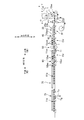
- FIG. 1A is a schematic top view of the connecting article 11a
- FIG. 1B is a view taken along the line BB in FIG. 1A
- FIG. 1C is a view taken along the line CC in FIG. 1A.
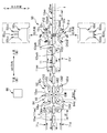
- 2 is a schematic side view of an end seal and perforation device 50.
- FIG. 3 is a schematic side view of an inspection conveyor 70.
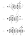
- FIG. 7A to 7C are schematic side views of other embodiments of the detaching device 60.
- a predetermined number of the individual packaged products are connected from a continuous body of individual packaged products formed by connecting a plurality of individual packaged products in which absorbent articles are individually accommodated in a lined-up state through a perforated portion.
- the manufacturing apparatus of the connection product of the individual package goods which concerns on an absorbent article characterized by having.
- a connected product in which the predetermined number of individual packaged products are connected can be separated from a continuous body of individual packaged products. And it is possible to change the consecutive number by changing the predetermined number. Therefore, it becomes possible to easily cope with the station number change.
- the connected product is separated from the continuous body by cutting the perforated portion, it is not necessary to use a blade member as a separating device. Therefore, it is not necessary to perform maintenance work accompanying wear of the blade member, and labor can be reduced.
- An apparatus for manufacturing a linked product of individually packaged products relating to such an absorbent article It is desirable that the separation device cuts the perforation portion by pulling the perforation portion in the transport direction when the identified perforation portion passes through the separation device.
- disconnects the perforation part specified as a perforation part to be cut
- the specific device includes an input unit that inputs information relating to the predetermined number, and a memory that updates and records the predetermined number based on the information input from the input unit, It is preferable that the specifying device specifies the perforation portion to be cut corresponding to the predetermined number recorded in the memory, and causes the separation device to cut the identified perforation portion.
- the predetermined number can be easily changed by inputting information on the predetermined number from the input unit. Therefore, the number of stations can be changed easily.
- the separating apparatus has a pair of nip roll mechanisms having a pair of rolls that rotate while sandwiching the continuous body from the thickness direction of the continuous body, aligned in the transport direction,
- the perforated portion to be cut passes between the pair of nip roll mechanisms, the conveyance speed value of the continuous body in the downstream nip roll mechanism of the pair of nip roll mechanisms, and the upstream nip roll mechanism It is preferable that the perforated portion is pulled and cut in the transport direction by increasing the difference from the transport speed value of the continuum.
- the continuous body of the downstream nip roll mechanism is The perforated portion to be cut is cut by increasing the difference between the conveyance speed value and the conveyance speed value of the continuous body in the upstream nip roll mechanism. Therefore, it is possible to reliably cut only the perforated portion to be cut among the plurality of perforated portions.
- An apparatus for manufacturing a linked product of individually packaged products relating to such an absorbent article It is preferable that the distance between the pair of nip roll mechanisms is set so that the number of perforations existing between the pair of nip roll mechanisms is always one or less. According to the manufacturing apparatus of the connected product of the individually packaged product relating to such an absorbent article, since the number of perforations existing between the pair of nip roll mechanisms is always one or less, the pair of nip roll mechanisms When the perforated portion to be cut passes between them, only the perforated portion can be reliably cut.
- An apparatus for manufacturing a linked product of individually packaged products relating to such an absorbent article Except when cutting the perforated portion to be cut, when the transport speed value of the continuous body and the connected product transported by the cutting device is a first speed value, On the downstream side in the transport direction with respect to the separation device, there is a downstream transport device that transports the continuous body and the connected product at a transport speed value faster than the first speed value, It is desirable to have a first inspection device that inspects the overall length dimension of the connected product in the transport direction during or after the transport of the connected product by the downstream transport device.
- the continuous material and the connected product are the first while the continuous material and the connected product are transferred from the separating device to the downstream transport device.
- the speed is accelerated from the speed value to the transport speed value of the downstream transport device.
- the individual packages of the continuous body and the connected product are generally based on the difference between the transport speed value and the first speed value. Is pulled in the conveying direction to remove slack and wrinkles. Therefore, the inspection of the overall length of the connected product can be performed in a state in which the slackness of the connected product is removed, and the inspection can be accurately performed.
- An apparatus for manufacturing a linked product of individually packaged products relating to such an absorbent article It is desirable to have a second inspection device for inspecting the presence or absence of a perforated portion cut out of the perforated portions to be included in the connected product during conveyance of the connected product. According to such an apparatus for manufacturing a connected product of individually packaged products relating to absorbent articles, unintentional cutting of the perforated portion of the connected product can be reliably detected.
- An apparatus for manufacturing a linked product of individually packaged products relating to such an absorbent article At a position upstream of the separating device in the transport direction, A wrapping device for wrapping a plurality of the absorbent articles conveyed in the conveying direction in a state aligned in the conveying direction with a continuous sheet for packaging conveyed in the conveying direction; A pair of sealing parts are formed in each part between the absorbent articles in the continuous sheet to individually accommodate the absorbent article, and at a position between the pair of sealing parts in each part.
- a continuous body generating device that generates a continuous body of the individually packaged product by forming the perforated portion;
- the continuous body generating device has a pair of roll-shaped members that rotate in conjunction with the conveying operation of the continuous sheet while facing an outer peripheral surface of the continuous sheet.
- On the outer peripheral surface of at least one roll-shaped member of the pair of roll-shaped members a pair of pressing portions that press-form the pair of sealing portions on the continuous sheet is provided,
- a blade member that presses and forms the perforated portion on the continuous sheet is provided on the outer peripheral surface of at least one of the pair of roll-shaped members, When processing the perforated portion, it is desirable that the blade member is located at a position between the pair of pressing portions.
- the manufacturing apparatus of the connected product of the individually packaged product according to such an absorbent article by passing through the roll gap between the pair of roll-shaped members included in the continuous body generating device, the pair of sealing portions and The perforated portion can be formed almost simultaneously. Therefore, the relative positional relationship between the formation position of the sealing portion and the formation position of the perforated portion in the continuous sheet can be maintained almost always constant. As a result, problems that tend to occur when the device that operates the pressing portion and the device that operates the blade member are separate devices, such as a problem of fluctuations in the relative positional relationship that may occur due to poor synchronization between these devices. Etc. can be avoided reliably.
- a predetermined number of the individual packaged products are connected from a continuous body of individual packaged products formed by connecting a plurality of individual packaged products in which absorbent articles are individually accommodated in a lined-up state through a perforated portion.
- a method of manufacturing the connected product by separating the connected product of the individually packaged product, Identifying the perforations to be cut corresponding to the predetermined number from the perforations of the continuum that is transported with the alignment direction as the transport direction; Severing the identified perforated portion to separate the connected product in which the predetermined number of individually packaged products are connected from the continuous body transported along the transport direction.
- a connected product in which the predetermined number of individual packaged products are connected can be separated from a continuous body of individual packaged products. And it is possible to change the consecutive number by changing the predetermined number. Therefore, it becomes possible to easily cope with the station number change.
- the connected product is separated from the continuous body by cutting the perforated portion, it is not necessary to use a blade member as a separating device. Therefore, it is not necessary to perform maintenance work accompanying wear of the blade member, and labor can be reduced.
- the manufacturing apparatus of this embodiment is an apparatus which manufactures the connection goods 11a of the individual package goods 11,11 ... which concern on the disposable diaper 1 as an example of an absorbent article.
- FIG. 1A shows a schematic top view of the connecting article 11a
- FIG. 1B shows a view taken along the line BB in FIG. 1A
- FIG. 1C shows a view taken along the line CC in FIG. 1A. ing.
- FIG. 1A a partially enlarged view is also shown.
- the connected product 11a of the individually packaged products 11, 11... Is a plurality of individually packaged products 11, 11. Is.
- a so-called ten-line product in which ten individual packages 11, 11,... Are continuously arranged in a row is shown as an example.
- the connected product 11a in FIG. 1A is long and flexible with a length corresponding to, for example, 10 diapers 1, 1... Corresponding to the number of stations, and a length corresponding to, for example, 10 stations.
- Packaging sheet 12a On the packaging sheet 12a, ten diapers 1, 1,... Are placed in a line with the longitudinal direction of the packaging sheet 12a as the alignment direction in a state of being spaced apart from each other.
- each edge part 12ae and 12ae of the width direction of the packaging sheet 12a are piled up on each diaper 1, and the packaging sheet 12a was made into the cylinder shape, and each these edge parts 12ae and 12ae heat By joining with a seal
- a perforated perforated portion 12ac is also formed at a position between the pair of sealing portions 12as and 12as. And it can be separated for each individual packaged article 11 at the perforated part 12ac.
- a nonwoven fabric or a resin film mainly composed of resin fibers is used as the material of the packaging sheet 12a.
- FIG. 2 shows a schematic side view of the packaging line.
- a wrapping device 30, a center seal device 40, an end seal and perforation device 50, a separating device 60, and an inspection conveyor 70 are arranged side by side along the transport direction.
- a transport device such as a belt conveyor CV or a transport roller may be provided adjacent to the upstream side or the downstream side of these devices 30, 40, 50, 60, 70.
- the belt conveyor CV is located immediately upstream of the wrapping device 30, between the center seal device 40 and the end seal and perforation device 50, and between the end seal and perforation device 50 and the separation device 60.
- These belt conveyors CV are provided for conveying the diaper 1 and the continuous body 12aa of the packaging sheet 12a.
- Such a packaging line is fed with a plurality of diapers 1, 1... In a line along the conveying direction from the production line of the upper diaper 1.
- Each diaper 1 is transported at a predetermined alignment pitch P in the same direction with a space between the diapers 1 and 1 adjacent in the transport direction.
- the continuous body 12aa (henceforth continuous sheet 12aa) of the packaging sheet 12a merges from the downward
- Each of the diapers 1, 1... Is transported integrally with the continuous sheet 12aa along the transport direction while being placed on the continuous sheet 12aa.
- each diaper 1 placed on the continuous sheet 12aa passes through the wrapping device 30.
- the device 30 causes the end portions 12aae and 12aae in the width direction of the continuous sheet 12aa to move upward. While the sheet 12aa is bent into a cylindrical shape, the end portions 12aae and 12aae are overlapped with each other, whereby each of the diapers 1, 1... Is wrapped in the cylindrical sheet 12aa.
- each diaper 1, 1... Wrapped in the cylindrical continuous sheet 12aa passes through the center seal device 40.
- the device 40 causes the end portions 12aae and 12aae of the continuous sheet 12aa to be passed. Bonding processing is performed to each other, and thereby the shape of the continuous sheet 12aa is fixed to a cylindrical shape.
- heat sealing is applied as the joining process of the end portions 12aae and 12aae, but the present invention is not limited to this, and bonding with an adhesive may be used.
- the end seal and perforation device 50 passes, and in that case, the device 50 causes a pair of sealing portions 12as, a pair of diapers 1 and 1 between the diapers 1 and 1 in the cylindrical continuous sheet 12aa to be formed. 12as is formed, and a perforated perforated portion 12ac is also formed at a portion between the pair of sealing portions 12as and 12as in each portion 12aab.
- each diaper 1 will be in the state which can be cut
- heat sealing is applied as the forming process of the sealing portion 12as.
- the present invention is not limited to this, and bonding with an adhesive may be used.
- the continuous body 11aa of the individually packaged products 11, 11... Passes through the separating device 60.
- the continuous body 11aa has a series of 10 parts from among the plurality of perforated portions 12ac, 12ac.
- the perforated part 12ac to be cut corresponding to the target station number (manufactured station number) to be manufactured is specified, and only the specified perforated part 12ac is selectively cut, thereby the target station number ( In this example, 10 linked individual packaged articles 11, 11,...
- the connected product 11a passes through the inspection conveyor 70.
- the connected product 11a is inspected with the full length L11a.
- the connected product 11a is distributed to the regular conveyance path Tg for non-defective products or the discharge path Tb for defective products.
- the non-defective connected product 11a is sent to the shipping process in the lower process through the regular transport path Tg.
- the reason why the inspection of the overall length L11a is necessary is that the connected product 11a has perforations 12ac, 12ac,..., And is unintentionally cut by the perforations 12ac due to the transport tension acting during transport. This is because there is a risk of losing.
- each device 30, 40, 50, 60, 70 of the packaging line which is the manufacturing device of the present embodiment will be described.
- the width direction is also called “CD direction”.
- the longitudinal direction of the connected product 11a, the width direction of the connected product 11a, and the thickness direction of the connected product 11a are orthogonal to each other. Therefore, the MD direction, the CD direction, and the thickness direction are also orthogonal to each other.
- the MD direction is an arbitrary direction parallel to the paper surface. That is, as shown in FIG. 2, when two directions orthogonal to each other in the plane of the page are defined as a vertical direction and a front-back direction, an arbitrary direction defined by these two directions is the MD direction. In addition, the up-down direction faces the vertical direction, and the front-back direction faces the horizontal direction. Further, the CD direction is the direction penetrating the paper surface of FIG. 2, and in this example, the CD direction is the horizontal direction.
- the wrapping device 30 is a known device 30. That is, as shown in FIG. 2, the continuous sheet 12aa on which the diaper 1 is placed is conveyed along the MD direction, and is arranged on both sides in the CD direction while facing the conveying surface of the belt conveyor 32. A pair of guide plates 34a and 34b. When the continuous sheet 12aa conveyed by the conveying surface of the belt conveyor 32 passes through the positions of the guide plates 34a and 34b, the respective guide plates 34a and 34b respectively correspond to the corresponding end portions 12aae and 12aae of the continuous sheet 12aa.
- the center seal device 40 has a heating unit 42 heated to a predetermined temperature. Then, when the continuous sheet 12aa in the state of wrapping the diaper 1 in a cylindrical shape passes through the position of the heating unit 42, the heating unit 42 is placed between the end portions 12aae and 12aae of the stacked continuous sheets 12aa. For example, the end portions 12aae and 12aae are brought into contact with each other from above and heated and melted to join the end portions 12aae and 12aae. And thereby, the shape of continuous sheet 12aa is fixed to a cylinder shape.
- FIG. 3 shows a schematic side view of the end seal and perforation device 50.
- the device 50 (corresponding to a continuous body generating device) is a device that forms a pair of sealing portions 12as and 12as and a perforated portion 12ac simultaneously on a cylindrical continuous sheet 12aa.
- a pair of upper and lower rolls 51u, 51d (corresponding to a roll-shaped member) having processing portions 52u, 52d for forming the sealing portions 12as, 12as and the perforated portion 12ac on the outer peripheral surface are used as the main body.
- a pair of sealing portion convex portions 53us, 53us (corresponding to a pressing portion) for forming the pair of sealing portions 12as, 12as on the continuous sheet 12aa, Both the perforation blade 53uc (corresponding to the blade member) for forming the perforation portion 12ac on the sheet 12aa are provided close to each other, and the lower processing portion 52d of the lower roll 51d is provided with the pair of sealing members.
- a pair of receiving portions 53ds, 53ds for receiving the stopper convex portions 53us, 53us and a receiving blade 53dc for receiving the perforating blade 53uc are provided close to each other.
- the upper and lower rolls 51u and 51d are driven and rotated in synchronization with the conveying operation of the continuous sheet 12aa by a servo motor (not shown) as a drive source. Therefore, when each portion 12aab between the diapers 1 and 1 in the continuous sheet 12aa passes through the gap G51 between the upper and lower rolls 51u and 51d, the upper processing portion 52u and the lower processing portion 52d face each other. A pair of sealing portions 12as and 12as and a perforated portion 12ac are formed in each portion 12aab. And thereby, each diaper 1 is made into the state which can be cut
- the upper processing portion 52u and the lower processing portion 52d may be provided one by one for the upper roll 51u and the lower roll 51d, but in this example, four processings are provided as a plurality of examples, respectively, in order to increase the production speed. .., 52d, 52d,... Are provided. Therefore, in this example, each time the upper roll 51u and the lower roll 51d make one rotation, a pair of sealing portions 12as and 12as and a perforated portion 12ac are formed at four locations of the continuous sheet 12aa. That is, for each rotation of the upper and lower rolls 51u, 51d, four individual packages 11, 11,.
- the arc distance D52u on the orbit between the upper processing parts 52u and 52u adjacent in the rotation direction and the arc distance D52d on the orbit between the lower processing parts 52d and 52d adjacent in the rotation direction are: Each is set to be approximately equal to the alignment pitch P in the MD direction of the diapers 1 in the continuous sheet 12aa. Therefore, in this apparatus 50, the continuous sheet is rotated by rotating the upper and lower rolls 51u and 51d around the upper processing portion 52u and the lower processing portion 52d at a circumferential speed value V52 that is substantially the same as the conveyance speed value V12aa of the continuous sheet 12aa.
- the pair of sealing portions 12as and 12as and the perforated portion 12ac can be formed corresponding to each portion 12aab between the diapers 1 and 1 on the 12aa, and as a result, the conveyance speed value V12aa and the peripheral speed during processing.
- the formation of the pair of sealing portions 12as and 12as and the perforated portion 12ac due to a relative difference from the value V52 is effectively prevented from becoming unstable.
- Rotating the upper and lower rolls 51u and 51d in synchronization with the conveying operation of the continuous sheet 12aa is performed by a synchronization signal. That is, in this packaging line, a synchronization signal (for example, a rotation angle signal of 0 to 360 °) is generated with one cycle corresponding to one individual packaged product 11 as a transport operation, and the belt is based on this synchronization signal.
- a synchronization signal for example, a rotation angle signal of 0 to 360 °
- all the devices 30, 40, 50, 60, and 70 including the conveyor device such as the conveyor CV are controlled to operate.
- the upper and lower rolls 51u and 51d are no exception, and the servo motors of the upper and lower rolls 51u and 51d are position-controlled based on the synchronization signal, thereby synchronizing with the conveying operation of the continuous sheet 12aa.
- the upper and lower rolls 51u, 51d have four processing portions 52u, 52u,..., 52d, 52d, respectively, so that one-quarter rotation per cycle of the synchronization signal.
- the position of each servomotor is controlled so that a pair of sealing portions 12as and 12as and a perforated portion 12ac are formed in each portion 12aab between the diapers 1 and 1 in the continuous sheet 12aa. ing.
- the separating device 60 corresponds to the target number of stations (the number of stations in the manufacturing specification of the connected product) to be manufactured, such as 10 stations, from among the plurality of perforated portions 12ac, 12ac... Then, only the perforated portion 12ac to be identified is cut, and the connected product 11a formed by connecting the individual packaged products 11, 11... As a device to manufacture as.
- the apparatus 60 has a pair of nip roll mechanisms 62 and 64 arranged side by side in the MD direction.
- Each nip roll mechanism 62, 64 has a pair of upper and lower nip rolls 62u, 62d, 64u, 64d that are driven and rotated about rotation axes C62, C64 along the CD direction.
- the upstream nip roll mechanism 62 positioned on the upstream side sandwiches the continuum 11aa from the thickness direction on the outer peripheral surface, while driving and rotating the pair of nip rolls 62u so as to feed the continuum 11aa downstream in the MD direction.
- downstream nip roll mechanism 64 located downstream of the upstream nip roll mechanism 62 also holds the continuum 11aa in the MD direction while slightly sandwiching the continuum 11aa from the outer peripheral surface from the thickness direction. It has a pair of upper and lower nip rolls 64u and 64d that are driven and rotated so as to be sent downstream.
- the nip rolls 62u, 62d, 64u, and 64d of the upstream nip roll mechanism 62 and the downstream nip roll mechanism 64 are driven and rotated by a servo motor as a drive source, and the peripheral speed values V62 and V64 are substantially continuous. It is controlled so as to be aligned with the conveyance speed value V11aa of the body 11aa.
- the peripheral speed value V62 of the upstream nip roll mechanism 62 is set to V1 as a steady speed value
- the peripheral speed value V64 of the downstream nip roll mechanism 64 is The steady speed value (corresponding to the first speed value) is set to V1 to 1.06V1.
- the controller 66 described later detects that the perforated portion 12ac has reached between the upstream nip roll mechanism 62 and the downstream nip roll mechanism 64, only the peripheral speed value V64 of the downstream nip roll mechanism 64 is detected. Is instantaneously increased from the steady speed value to return to the steady speed value. For example, the peripheral speed value V62 of the upstream nip roll mechanism 62 is maintained at the steady speed value V1, but the peripheral speed value V64 of the downstream nip roll mechanism 64 is increased to a speed value of 2.95V1, and the increase is made. After the speed, it is immediately returned to the above-mentioned steady speed value V1 to 1.06V1.
- the transport speed value V11aa of the continuum 11aa in the upstream nip roll mechanism 62 is maintained substantially at the steady speed value V1 of the peripheral speed value V62, but the transport speed value V11aa in the downstream nip roll mechanism 64 is The peripheral speed value V64 is instantaneously increased to 2.95V1 instantaneously.
- the perforated portion 12ac to be cut is pulled in the MD direction by the upstream nip roll mechanism 62 and the downstream nip roll mechanism 64. Only the perforated portion 12ac is selectively cut.
- the connected product 11a having the individual packaged products 11, 11,... Corresponding to the target number is separated from the continuous body 11aa and manufactured.
- the period during which the above-described peripheral speed value V64 is increased from the steady speed value is defined by the conveyance amount in the MD direction of the continuous body 11aa.
- the conveyance amount during the above-described speed-up period is set to an arbitrary value that is equal to or less than the length in the MD direction of one individual packaged article 11 at the time of separation, and preferably the length of one individual packaged article 11 The length is preferably set to 10% to 30%.
- the appropriate value of the peripheral speed value V64 at the time of acceleration can be changed according to the cutting strength of the perforated portion 12ac. Therefore, the peripheral speed value V64 at the time of acceleration is determined by repeating experiments and trial operations as appropriate in consideration of the specifications of the perforated portion 12ac and the like. Therefore, it is not limited to 2.95V that is the value of the exemplified peripheral speed value V64.
- the distance D60 in the MD direction between the pair of nip roll mechanisms 62, 64 is such that the number of perforated portions 12ac existing in the distance D60 is always one or less. Is set. For example, it is set to a value smaller than the alignment pitch P of the diapers 1 that is the overall length dimension of the individual packaged product 11 in the alignment direction. Therefore, when the perforated portion 12ac to be cut passes between the pair of nip roll mechanisms 62 and 64, the perforated portions 12ac and 12ac adjacent to the upstream and downstream of the perforated portion 12ac are not cut. Only the perforated portion 12ac to be cut can be reliably selected and cut.
- the identification of the perforated portion 12ac to be cut corresponding to the target station number that is, the detection that the perforated portion 12ac to be cut enters between the upstream nip roll mechanism 62 and the downstream nip roll mechanism 64 is separated. This is done by a controller 66 that controls the device 60.
- the controller 66 (corresponding to a specific device) is a so-called computer or PLC (programmable logic controller) or the like, and has a processor and a memory.
- the controller 66 receives the above-described synchronization signal.
- the memory stores a counter-and-comparison program that counts the cycle of the synchronization signal and compares the count value with a predetermined value recorded in the memory. Further, a numerical value of the target station number is recorded as the predetermined value in the memory.
- the processor reads the counter-and-comparison program from the memory and executes it to count the cycle of the synchronization signal, and each time the count value increases, the count value is the numerical value of the target station number recorded in the memory. Compare with When the count value matches the numerical value of the target station number, the controller 66 determines that the perforated portion 12ac to be cut has entered between the upstream nip roll mechanism 62 and the downstream nip roll mechanism 64. The controller 66 instantaneously increases the speed of the servo motor of the downstream nip roll mechanism 64 to cut the perforated portion 12ac. If the controller 66 controls the separation device 60 in this way, the separation processing is accelerated once and the separation processing is performed every time the number of individual packaged articles 11, 11.
- the connected product 11a in which the individually packaged products 11, 11... Are connected by the target number is separated from the continuous body 11aa and manufactured.
- the counter value is reset to zero, and the counter-and-comparison program is set up so as to prepare for the counting of the next station number.
- the perforated portion 12ac to be cut may be specified by inputting the rotation signal to the controller 66 and counting as described above.
- the controller 66 has an input unit (not shown) such as a keyboard and a mouse, and can update the predetermined value in the memory based on information on the target station number input from the input unit. It is good to be configured. For example, when a numerical value of the target station number is directly input as information related to the target station number from the input unit, the predetermined value in the memory may be updated to the input numerical value. And if it is comprised in this way, it will become possible to change a target station number easily, and it will become possible to cope with change of station number of the connection goods 11a of the individually packaged goods 11,11 ... still more easily. .
- the information related to the target station number is not limited to the numerical value of the target station number.
- the information input by the selection operation using the input unit is the above-described information.
- the controller 66 rewrites the predetermined value in the memory to the numerical value of the target station number corresponding to this information.
- a separation confirmation sensor for confirming whether or not the perforated portion 12ac to be cut is separated at a position between the upstream nip roll mechanism 62 and the downstream nip roll mechanism 64. 68 may be provided.
- the gaze point of the separation confirmation sensor 68 that is, the monitoring target position in the MD direction, is a position downstream in the MD direction from the position where the perforated portion 12ac to be cut is conveyed when the speed increase command is output. Is set.
- the controller 66 determines that the perforated portion 12ac to be cut is not cut, and gives a “cutting failure” alarm to the monitor of the controller 66, etc.
- the predetermined time is appropriately set by experiment or the like.
- the separation confirmation sensor 68 for example, a phototube is used, but the present invention is not limited to this. For example, an appropriate sensor such as a laser sensor is also applicable.
- FIG. 4 shows a schematic side view of the inspection conveyor 70.
- the inspection conveyor 70 it is inspected whether or not the total length L11a of the connected product 11a separated from the continuous body 11aa by the separating device 60 is within an assumed length range for the connected product 11a having the target number of stations. To do.
- the inspection result of the overall length L11a is longer than the upper limit value Lmax of the assumed length range, it is cut off at any perforated portion 12ac included in the connected product 11a, or the connected product 11a is provided. Empty that has not been accommodated in the diaper 1 in any one of the individually packaged products 11, 11. There is a possibility of any one of these three states. Therefore, the connected product 11a is discharged from the discharge route Tb as a defective product.
- the connected product 11a does not have the individual packaged products 11, 11,.
- the target number of stations is 10
- the number of stations is insufficient such as a 9-series product or an 8-series product. Therefore, the connected product 11a is also discharged from the discharge path Tb as a defective product.
- the reason why the total length L11a of the connected product 11a is longer than the upper limit value Lmax of the above-mentioned assumed length range is the empty individual package This is because the product 11 is thinner than the individually packaged product 11 in which the diaper 1 is correctly accommodated, and the entire length is extended by the thickness of the product.
- the inspection conveyor 70 includes a belt conveyor 71 provided immediately downstream of the separation device 60, a first inspection device 74 that inspects the overall length L 11 a of the connected product 11 a that the belt conveyor 71 conveys, and a first inspection device 74.
- the belt conveyor 71 (corresponding to the downstream transport device) has a pair of upper and lower endless belts 71u and 71d, and a transport path for the connected product 11a or the continuous body 11aa is formed between the endless belts 71u and 71d.
- the upper endless belt 71u is wound around a pair of rollers 72u and 72u arranged in the MD direction
- the lower endless belt 71d is also hung around a pair of rollers 72d and 72d arranged in the MD direction. ing.
- the endless belts 71u and 71d drive and circulate in conjunction with each other in a state where the connected product 11a or the continuous body 11aa is sandwiched from above and below in the thickness direction.
- the connected product 11a or the continuous body 11aa is conveyed downstream in the MD direction.
- the driving orbiting operation of the upper and lower endless belts 71u and 71d is performed by driving and rotating the rollers 72u and 72d by, for example, a servo motor (not shown) as a driving source.
- the overall length L71 of the conveying path of the belt conveyor 71 is set sufficiently longer than the upper limit value Lmax of the assumed length range of the overall length L11a of the connected product 11a.
- the circumferential speed value V71 of the endless belts 71u and 71d that is, the transport speed values V11a and V11aa of the connected article 11a and the continuous body 11aa by the belt conveyor 71 are the peripheral speeds corresponding to the transport speed values V11a and V11aa in the separating device 60.
- the steady speed value V1 of the value V62 and the steady speed values V1 to 1.06V1 of the peripheral speed value V64 are set to be larger values. In this example, for example, 1.65V1 is set as the steady speed value.
- a predetermined gap G11a is formed between the connected product 11a and the adjacent connected product 11a upstream thereof while being transported along the transport path of the belt conveyor 71, and thereby the connected product 11a. Is a defective product, the time required for the defective product discharge processing from the discharge path Tb is secured.
- the peripheral speed value V64 of the downstream nip roll mechanism 64 is steady. Based on the difference between the speed values V1 to 1.06V1 and the steady speed value 1.65V1 of the circumferential speed value V71 of the belt conveyor 71, each individual package 11, 11,... Is almost removed. Therefore, the inspection of the overall length L11a of the connected product 11a can be accurately performed.
- the first inspection device 74 includes inspection sensors 74 s 1, 74 s 2, 74 s 3 and inspection sensors 74 s 1, 74 s 2, which are installed at predetermined positions on the conveyance path of the belt conveyor 71.
- 74s3 has a controller 74c for determining whether the overall length L11a of the connected product 11a of the individually packaged products 11, 11,...
- the inspection sensors 74s1, 74s2, 74s3, three sensors are installed.
- the first sensor 74s1 is provided with a predetermined position in the downstream portion of the conveyance path of the belt conveyor 71 as a monitoring target position P74s1 (hereinafter also referred to as a first monitoring target position P74s1). And when the downstream end 11aed of the connection article 11a passes through the first monitoring target position P74s1, the passage is detected.
- the second sensor 74s2 is a lower limit value responsible sensor provided in correspondence with the lower limit value Lmin of the assumed length range described above. Therefore, the monitoring target position P74s2 of the second sensor 74s2 (hereinafter also referred to as the second monitoring target position P74s2) is basically the position where the downstream end 11aed of the non-defective connected product 11a is located at the first monitoring target position P74s1.
- the uppermost individual packaged product 11 of the connected product 11a is set at a theoretical position where it should theoretically be located.
- the theoretical position has a range, and the range is, for example, from the position of the downstream end 11ed of the uppermost individual packaged product 11 to the position of the upstream end 11eu.
- the second monitoring target position P74s2 is set to the lower limit value in the theoretical position, that is, the position of the downstream end 11ed of the most upstream individual packaged product 11.
- the third sensor 74s3 is an upper limit value charge sensor provided corresponding to the upper limit value Lmax of the assumed length range of the connected product 11a. Therefore, the monitoring target position P74s3 of the third sensor 74s3 (hereinafter also referred to as the third monitoring target position P74s3) is the same as that when the downstream end 11aed of the non-defective connected product 11a is located at the first monitoring target position P74s1.
- the upstream end 11aeu of the connected product 11a is set at a position upstream from the theoretical position that should theoretically be located by an assumed variation such as a dimensional tolerance.
- the assumed variation is set to a predetermined value E selected from the range of 0.1 to 0.2 pieces of the individually packaged product 11, and thereby the third monitoring target position P74s3 is The position is set upstream by the predetermined value E from the theoretical position.
- the connected product 11a is slightly extended in the MD direction by an action such as conveyance tension. Therefore, the theoretical position is slightly shifted to the upstream side from the position determined by both the first monitoring target position P74s1 and the design value of the overall length 11a which is the natural length of the connected product 11a. Therefore, such a theoretical position is obtained by, for example, an experimental method. That is, the connected product 11a is actually conveyed on the belt conveyor 71, and the position of the uppermost individual packaged product 11 when the first detection sensor 74s1 detects the downstream end 11aed of the connected product 11a is measured a plurality of times. The theoretical position is obtained.
- the controller 74c is, for example, a computer or a PLC, and output signals are input from the first, second, and third sensors 74s1, 74s2, and 74s3, respectively.
- the total length L11a of the connected product 11a is inspected as follows. First, the connected product 11 a separated from the continuous body 11 aa by the separating device 60 is conveyed downstream by the belt conveyor 71. When the downstream end 11aed of the connected product 11a passes through the first monitoring target position P74s1 during conveyance by the belt conveyor 71, a signal indicating that the passage has been detected is received from the first sensor 74s1 that has detected the passage. It is transmitted to the controller 74c. Then, the controller 74c checks the output states of the second sensor 74s2 and the third sensor 74s3 when this signal is received.
- the overall length L 11 a is longer than the assumed length range, and in this case, It corresponds to one of the three types of non-defective products (partially cut out of the perforated portion 12ac, complete cutting of the perforated portion 12ac, and presence of an empty individual packaged product 11).
- the output state of the second sensor 74s2 indicates “no connected product 11a”, as described above, the connected product 11a does not have the target number of individually packaged products 11 and the number of stations is insufficient. It corresponds to the aspect of.
- a photoelectric tube is used as each of the first to third sensors 74s1 to 74s3.
- the present invention is not limited to this, and an appropriate sensor such as a laser sensor can be applied.
- the distribution mechanism 75 is connected to the downstream of the belt conveyor 71 in the MD direction, and sucks and holds the connected product 11a from above and conveys it downstream in the MD direction.
- the belt conveyor 77 disposed on the lower side facing only the downstream portion in the MD direction of the suction belt conveyor 76, and the upstream portion of the suction belt conveyor 76, and injecting air downward.
- the air injection device 78 for removing the defective connected product 11a downward from the suction belt conveyor 76 is provided.
- the space SPtb in which a belt conveyor does not exist is provided under the upstream part in the suction belt conveyor 76,
- the air injection device 78 is activated when the connected product 11a that is conveyed upward in the MD direction while being adsorbed upward by the suction belt conveyor 76 passes through the upstream portion of the suction belt conveyor 76.
- the connected product 11a falls to the lower discharge path Tb, and is thereby discharged from the regular transport path Tg. And if the connection goods 11a finishes passing, it will stop injecting air and will be in a standby state.
- the process of selectively operating the device 78 only for the connected product 11a determined to be defective is performed as follows, for example. Realized.
- the distance L78 from the first monitoring target position P74s1 of the first sensor 74s1 to the air injection device 78 is a known fixed value, and it is also known how many cycles of the synchronization signal the distance L78 corresponds to. is there. Therefore, the data of the distance L78 is recorded in advance in the memory of the controller 74c in the form of a converted value converted into the cycle number of the synchronization signal.
- both the output signal and the synchronization signal of the first sensor 74s1 are input to the controller 74c.
- the memory has a pass / fail determination flag, and the flag is determined by the inspection device 74.
- the data of the pass / fail judgment result which is the latest inspection result, is always overwritten and recorded.
- the controller 74c when the controller 74c receives a signal indicating that the first sensor 74s1 has passed through the first monitoring target position P74s1 of the first sensor 74s1, the controller 74c receives the signal indicating that the first sensor 74s1 has passed.
- the cycle of the synchronization signal is counted from the time point.
- the controller 74c refers to the pass / fail determination flag in the memory, and when the “non-defective flag” is recorded in the pass / fail determination flag, the air injection
- the connected product 11a is transported downstream through the regular transport path Tg without operating the device 78.
- the air injection device 78 is operated to inject air toward the connected product 11a.
- the connected product 11a is separated from the regular transport path Tg and discharged through the discharge path Tb.
- the air injection stop operation is performed, for example, when the upstream end 11aeu of the connection product 11a has finished passing the position of the air injection device 78 based on the count value of the synchronization signal.
- the quality of the overall length L11a of the connected product 11a is determined by referring to the output state of the second sensor 74s2 and the third sensor 74s3 based on the output signal of the first sensor 74s1.
- a defective product is erroneously determined as a good product depending on the situation.
- connection product 11a in the case where the connection product 11a is unintentionally cut at the center perforation portion 12ac in the MD direction due to the conveyance tension or the like, two five-part products 11a5 and 11a5 are used. Are generated, both of which are fraction defective with insufficient number of stations. Then, depending on the situation, as shown in FIG. 6, the output signal of the second sensor 74s2 of the inspection device 74 is “the connected product 11a exists” for the connected product 11a including the two fractional defective products 11a5 and 11a5. And the output signal of the third sensor 74s3 may indicate “no connected product 11a”. In this case, the above-described inspection apparatus 74 uses a connection consisting of these fraction defective products 11a5 and 11a5. The product 11a is erroneously determined to be a non-defective product.
- a second inspection device 84 is additionally provided, so that the presence or absence of cutting at the perforated portion 12ac not to be cut can be reliably inspected.
- the second inspection device 84 includes an inspection sensor 84s provided in, for example, an upstream portion of the inspection conveyor 71, and a controller 84c provided corresponding to the sensor 84s.
- a photoelectric tube 84s is used as the sensor 84s, and the photoelectric tube 84s constantly transmits an output value signal corresponding to the amount of received light to the controller 84c.
- the controller 84c compares the output value of this signal with predetermined threshold data, thereby detecting the presence or absence of cutting at the perforated portion 12ac that is not to be cut. That is, if there is a perforated portion 12ac in the connection product 11a, a gap G12ac is generated there. Therefore, the presence or absence of cutting is detected from the change in the light receiving state of the photoelectric tube 84s when the gap G12ac passes. Can do.
- the downstream end 11aed of the connected product 11a passes through the monitoring target position P84s of the photoelectric tube 84s after this time. It is considered as the time when.
- the controller 84c counts the cycle of the synchronization signal starting from the time point, and this count value spans a time range until it matches the number of cycles corresponding to the total length L11a of the connected product 11a of the target station number.
- the “non-defective flag” is recorded in the second pass / fail judgment flag provided in the memory of the controller 84c.
- the output value is out of the numerical range even once, it is considered that the gap G12ac is present, and the “flag indicating defective product” is recorded in the second pass / fail judgment flag.
- the second pass / fail determination flag is always overwritten and recorded.
- the air injection device 78 is operated based on the second pass / fail judgment flag, the connected product 11a composed of the short-numbered defective products 11a5 and 11a5 is discharged from the discharge path Tb, and the target station number Only good products can be sent to the regular transport path Tg.
- the controller 84c determines that the connected product 11a has reached the position of the air injection device 78.
- the controller 84c refers to the second pass / fail judgment flag, and when the “flag indicating a defective product” is recorded in the second pass / fail judgment flag, the controller 84c causes the air injection device 78 to It operates and injects air toward the connected product 11a, whereby the connected product 11a is separated from the regular transport path Tg and discharged from the discharge path Tb.
- the controller 84c causes the air injection device 78 to It operates and injects air toward the connected product 11a, whereby the connected product 11a is separated from the regular transport path Tg and discharged from the discharge path Tb.
- the “non-defective flag” is recorded in the second pass / fail judgment flag, the connected product 11a is transported downstream through the regular transport path Tg without operating the air injection device 78.
- such sensors 84s are provided at a plurality of locations on the belt conveyor 71, and the second pass / fail judgment flag is obtained when the pass / fail judgment result based on the signal from any one of the sensors 84s, 84s.
- a “flag indicating a defective product” may be recorded. In this way, it is possible to improve the detection accuracy of the connected product 11a having an insufficient number of stations.
- the dedicated sensor 84s is provided in the second inspection device 84 separately from the second and third sensors 74s2 and 74s3.
- the second and third sensors 74s2 and 74s3 are connected to the sensor 84s.
- the second and third sensors 74s2 and 74s3 may also be used as the sensor 84s. And if it does in this way, sensor 84s can be omitted and equipment cost can be reduced.
- the controller 84c of the second inspection apparatus 84 may also serve as the controller 74c of the first inspection apparatus 74.
- the defective connected products 11a discharged from the discharge path Tb those that are determined as defective due to insufficient number of stations are not defective products when viewed as the individually packaged products 11, 11,. .
- the connected products 11a, 11a having insufficient number of stations may be shipped after being aligned with the target number of stations by connecting them with an adhesive tape or the like.
- the separation device 60 has cut the perforated portion 12ac to be cut in the MD direction.
- the method for cutting the perforated portion 12ac is not limited to this, and for example, shearing may be used.
- shearing for example, when the perforated portion 12ac to be cut passes along the MD direction, the portion adjacent to the downstream side of the perforated portion 12ac in the continuous sheet 12aa and the perforated portion 12ac in the sheet 12aa.
- a first plate member that is arranged downstream in the MD direction and moves up and down, and an upper and lower side that is arranged upstream from the first plate member.
- Examples include a second plate member that moves up and down, and a drive mechanism that reversely moves the first plate and the second plate member.
- the conveyance speed value V11aa of the continuous body 11aa in the downstream nip roll mechanism 64 is set. By increasing the speed, the perforated part 12ac is pulled and cut in the MD direction with the upstream nip roll mechanism 62, but the invention is not limited to this.
- the conveyance speed value V11aa of the continuous body 11aa in the downstream nip roll mechanism 64 and the continuity in the upstream nip roll mechanism 62 are detected.
- the speed increasing process is not limited to the above.
- the conveyance speed value V11aa in the downstream nip roll mechanism 64 is reduced by reducing the conveyance speed value V11aa in the upstream nip roll mechanism 62 while maintaining the conveyance speed value V11aa in the downstream nip roll mechanism 64 substantially constant.
- the difference from the conveyance speed value V11aa in the upstream nip roll mechanism 62 is increased, and thereby, the tensile force in the MD direction is applied to the perforated portion 12ac to be cut while passing between the pair of nip roll mechanisms 62 and 64. May be cut.
- the pair of nip roll mechanisms 62 and 64 arranged in the MD direction are illustrated as shown in FIG. 3, but the present invention is not limited to this.
- a pair of upper and lower endless belts 162u, 162d ( An endless belt mechanism 162 (164) having 164u, 164d) may be used.
- the pair of upper and lower endless belts 162u, 162d (164u, 164d) can convey the continuous body 11aa from the thickness direction while being pressed, so that the nip roll mechanism 62 (64 ), The perforated portion 12ac to be cut can be pulled in the MD direction. Therefore, such a configuration may be used as the separation devices 60a and 60b.
- the separation device 60c may be configured by arranging two endless belt mechanisms 162 and 164 in the MD direction. That is, when the perforated portion 12ac to be cut passes between the endless belt mechanism 162 located on the upstream side in the MD direction and the endless belt mechanism 164 adjacent to the downstream side, the endless belts 162u and 164u of each other are passed.
- the perforated portion 12ac to be cut may be pulled in the MD direction for cutting by increasing the difference between the peripheral speed values V162 and V164.
- the air injection device 78 is used as a device for removing the defective connected product 11a from the suction belt conveyor 76 of the distribution mechanism 75 (for example, FIG. 5), but is not limited to this.
- a device (not shown) in which an obstacle member appears and disappears in the conveyance path of the suction belt conveyor 76 may be provided.
- the device by putting the obstacle member in the exiting state, it is possible to cause the coupling member 11a to collide with the obstacle member and disengage from the suction belt conveyor 76, while on the other hand, by placing the obstacle member in the submerged state, The conveyance by the suction belt conveyor 76 can be maintained.
- a configuration including the first to third sensors 74s1, 74s2, and 74s3 is shown as an example of the first inspection device 74, and the first sensor 74s1 detects the passage of the downstream end 11aed of the connection product 11a.
- the first sensor 74s1 detects the passage of the downstream end 11aed of the connection product 11a.
- the second sensor 74s2 and the third sensor 74s3 Based on the output states of the second sensor 74s2 and the third sensor 74s3 at the time of the determination, it has been determined whether or not the total length L11a of the connected product 11a is within the assumed length range, but is not limited thereto.
- a contact-type or non-contact-type speed measurement sensor (not shown) that measures the conveyance speed value V11a of the connected product 11a is provided at a predetermined position while facing the conveyance path of the belt conveyor 71.
- the speed measurement sensor transmits to the controller (not shown) in real time over the entire time from when the connected product 11a starts to pass through the monitoring target position (measurement target position) of the speed measurement sensor.
- the controller integrates the speed value to calculate the full length dimension L11a, and compares the calculated value of the full length dimension L11a with the data of the assumed length range recorded in the memory of the controller in advance. An inspection of L11a may be performed.
- the sensor may be separated and additionally installed near the device 60.
- the controller 66 integrates the velocity value transmitted from the sensor, thereby obtaining the length of the continuum 11aa that has passed the position.
- the length reaches the target length corresponding to the target station number, it is determined that the perforated portion 12ac to be cut has entered between the upstream nip roll mechanism 62 and the downstream nip roll mechanism 64.
- the downstream side nip roll mechanism 64 is accelerated to cut the continuous body 11aa.
- the integral value is reset to zero, so that the controller 66 is provided for the integration process of the next station number.
- the total length L11a of the connected product 11a is inspected while the connected product 11a is being conveyed by the belt conveyor 71 of the inspection conveyor 70.
- the present invention is not limited to this.
- a separate belt conveyor may be connected downstream of the belt conveyor 71, and the inspection may be performed during conveyance by the belt conveyor.
- the length L11a may be inspected after being conveyed by the belt conveyor 71.
- the inspection of the total length 11La is performed on the connected product 11a that has been extended in the MD direction when transferring from the separating device 60 to the belt conveyor 71, the inspection is accurate. Become.
- the end seal and perforation device 50 has a pair of upper and lower rolls 51u and 51d.
- the upper roll 51u is provided with a pair of sealing portion convex portions 53us and 53us as a pair of pressing portions, and is provided with a perforating blade 53uc as a blade member, and the lower roll 51d
- the pair of receiving portions 53ds and 53ds are provided and the receiving blade 53dc is provided, the present invention is not limited to this. That is, the up-and-down arrangement of the sealing portion convex portions 53us and 53us and the receiving portion may be reversed, and the up-and-down arrangement of the perforating blade 53uc and the receiving blade 53dc may be reversed.
- a pair of sealing convex portions 53us, 53us is provided on one roll 51u (51d) of the pair of upper and lower rolls 51u, 51d, and the other roll 51d (51u) is provided.
- a perforated blade 53uc may be provided.
- the perforation blade 53uc processes the perforation portion 12ac in the continuous sheet 12aa, the perforation blade 53uc is positioned between the corresponding pair of sealing portion convex portions 53us, 53us.
- the upper and lower rolls 51u and 51d are rotated, and such rotation operation is realized by position control of the servo motor.
- the disposable diaper 1 was illustrated as an example of an absorbent article, if it is an article which absorbs a wearer's excretion liquid, it will not restrict to this at all, for example, an absorbent article is a sanitary napkin. There may be.
Landscapes
- Health & Medical Sciences (AREA)
- Engineering & Computer Science (AREA)
- Epidemiology (AREA)
- Life Sciences & Earth Sciences (AREA)
- Biomedical Technology (AREA)
- Heart & Thoracic Surgery (AREA)
- Vascular Medicine (AREA)
- Animal Behavior & Ethology (AREA)
- General Health & Medical Sciences (AREA)
- Public Health (AREA)
- Veterinary Medicine (AREA)
- Manufacturing & Machinery (AREA)
- Mechanical Engineering (AREA)
- Auxiliary Devices For And Details Of Packaging Control (AREA)
- Absorbent Articles And Supports Therefor (AREA)
- Containers And Plastic Fillers For Packaging (AREA)
Priority Applications (1)
| Application Number | Priority Date | Filing Date | Title |
|---|---|---|---|
| IN1822DEN2015 IN2015DN01822A (enExample) | 2012-08-08 | 2013-07-23 |
Applications Claiming Priority (2)
| Application Number | Priority Date | Filing Date | Title |
|---|---|---|---|
| JP2012-176303 | 2012-08-08 | ||
| JP2012176303A JP5986842B2 (ja) | 2012-08-08 | 2012-08-08 | 吸収性物品に係る個別包装品の連結品の製造装置、及び製造方法 |
Publications (1)
| Publication Number | Publication Date |
|---|---|
| WO2014024672A1 true WO2014024672A1 (ja) | 2014-02-13 |
Family
ID=50067906
Family Applications (1)
| Application Number | Title | Priority Date | Filing Date |
|---|---|---|---|
| PCT/JP2013/069885 Ceased WO2014024672A1 (ja) | 2012-08-08 | 2013-07-23 | 吸収性物品に係る個別包装品の連結品の製造装置、及び製造方法 |
Country Status (3)
| Country | Link |
|---|---|
| JP (1) | JP5986842B2 (enExample) |
| IN (1) | IN2015DN01822A (enExample) |
| WO (1) | WO2014024672A1 (enExample) |
Cited By (3)
| Publication number | Priority date | Publication date | Assignee | Title |
|---|---|---|---|---|
| WO2016006289A1 (ja) * | 2014-07-09 | 2016-01-14 | ユニ・チャーム株式会社 | 吸収性物品に係る個別包装品の連結品の製造方法、及び製造装置 |
| JP6022122B1 (ja) * | 2015-12-09 | 2016-11-09 | ユニ・チャーム株式会社 | 連結包装製品の製造方法 |
| CN107054748A (zh) * | 2017-04-08 | 2017-08-18 | 汕头市东升食品有限公司 | 全自动卧式食品包装机 |
Families Citing this family (4)
| Publication number | Priority date | Publication date | Assignee | Title |
|---|---|---|---|---|
| JP6026061B1 (ja) * | 2015-11-30 | 2016-11-16 | ユニ・チャーム株式会社 | 連結包装製品の製造方法 |
| WO2017094088A1 (ja) * | 2015-11-30 | 2017-06-08 | ユニ・チャーム株式会社 | 連結包装製品の製造方法 |
| EP3330190A1 (en) * | 2016-12-02 | 2018-06-06 | Swedish Match North Europe AB | Method and arrangement for portion-packing of an oral pouched snuff product |
| CN109259934B (zh) * | 2018-09-06 | 2021-08-03 | 瑞光(上海)电气设备有限公司 | 多连包卫生用品的制造系统及制造方法 |
Citations (4)
| Publication number | Priority date | Publication date | Assignee | Title |
|---|---|---|---|---|
| JPS519986A (en) * | 1974-07-15 | 1976-01-27 | Om Ltd | Renzokutaijobutsuno sumaitsuzuriateno hikichigirisochi |
| JPH04200545A (ja) * | 1990-11-30 | 1992-07-21 | Kao Corp | 生理用ナプキンの分離包装装置 |
| JP2003135518A (ja) * | 2001-11-06 | 2003-05-13 | Daio Paper Corp | 紙おむつの製品カッターユニット、及び紙おむつの切断方法 |
| JP2006306418A (ja) * | 2005-04-27 | 2006-11-09 | General Packer Co Ltd | 二連パックの切り離し装置 |
Family Cites Families (2)
| Publication number | Priority date | Publication date | Assignee | Title |
|---|---|---|---|---|
| JPH07187497A (ja) * | 1993-12-27 | 1995-07-25 | Dainippon Printing Co Ltd | 折製品自動突揃装置 |
| JP4703318B2 (ja) * | 2005-08-19 | 2011-06-15 | デュプロ精工株式会社 | 連続用紙処理装置および運転制御方法 |
-
2012
- 2012-08-08 JP JP2012176303A patent/JP5986842B2/ja not_active Expired - Fee Related
-
2013
- 2013-07-23 WO PCT/JP2013/069885 patent/WO2014024672A1/ja not_active Ceased
- 2013-07-23 IN IN1822DEN2015 patent/IN2015DN01822A/en unknown
Patent Citations (4)
| Publication number | Priority date | Publication date | Assignee | Title |
|---|---|---|---|---|
| JPS519986A (en) * | 1974-07-15 | 1976-01-27 | Om Ltd | Renzokutaijobutsuno sumaitsuzuriateno hikichigirisochi |
| JPH04200545A (ja) * | 1990-11-30 | 1992-07-21 | Kao Corp | 生理用ナプキンの分離包装装置 |
| JP2003135518A (ja) * | 2001-11-06 | 2003-05-13 | Daio Paper Corp | 紙おむつの製品カッターユニット、及び紙おむつの切断方法 |
| JP2006306418A (ja) * | 2005-04-27 | 2006-11-09 | General Packer Co Ltd | 二連パックの切り離し装置 |
Cited By (5)
| Publication number | Priority date | Publication date | Assignee | Title |
|---|---|---|---|---|
| WO2016006289A1 (ja) * | 2014-07-09 | 2016-01-14 | ユニ・チャーム株式会社 | 吸収性物品に係る個別包装品の連結品の製造方法、及び製造装置 |
| JP2016016891A (ja) * | 2014-07-09 | 2016-02-01 | ユニ・チャーム株式会社 | 吸収性物品に係る個別包装品の連結品の製造方法、及び製造装置 |
| JP6022122B1 (ja) * | 2015-12-09 | 2016-11-09 | ユニ・チャーム株式会社 | 連結包装製品の製造方法 |
| WO2017098613A1 (ja) * | 2015-12-09 | 2017-06-15 | ユニ・チャーム株式会社 | 連結包装製品の製造方法 |
| CN107054748A (zh) * | 2017-04-08 | 2017-08-18 | 汕头市东升食品有限公司 | 全自动卧式食品包装机 |
Also Published As
| Publication number | Publication date |
|---|---|
| JP2014033797A (ja) | 2014-02-24 |
| IN2015DN01822A (enExample) | 2015-05-29 |
| JP5986842B2 (ja) | 2016-09-06 |
Similar Documents
| Publication | Publication Date | Title |
|---|---|---|
| JP5986842B2 (ja) | 吸収性物品に係る個別包装品の連結品の製造装置、及び製造方法 | |
| US9096405B2 (en) | Defective-workpiece discharging device | |
| EP2412348B1 (en) | Apparatus and method for minimizing waste and improving quality and production in web processing operations by automated threading and re-threading of web materials | |
| USRE48182E1 (en) | Apparatus and method for minimizing waste and improving quality and production in web processing operations by automatic cuff defect correction | |
| CA2697786C (en) | Apparatus and method for intermittent application of stretchable web to target web | |
| JP5841759B2 (ja) | 吸収性物品の排出方法 | |
| US20140339046A1 (en) | Methods and Apparatuses for Rejecting Defective Absorbent Articles from a Converting Line | |
| KR20110127649A (ko) | 개인용 위생용품 제조를 위한 기계 | |
| EP2986261B1 (en) | Machine and method for making absorbent sanitary articles | |
| US11981520B2 (en) | Apparatus and method for web twist defect correction | |
| JP6059904B2 (ja) | 吸収性物品の包装品の製造装置、及び製造方法 | |
| EP2996653A1 (en) | Methods and apparatuses for folding absorbent articles | |
| WO2013005682A1 (ja) | 吸収性物品の排出方法 | |
| JP6629553B2 (ja) | 包装袋の製造方法 | |
| JP6846211B2 (ja) | 回転式トップシール装置 | |
| EP1279389A2 (en) | A feed unit supplying strip material to a line for the manufacture of personal hygiene items | |
| KR20250046862A (ko) | 샌드위치 포장 자동화 장치 | |
| JP2025085085A (ja) | 吸収性衛生物品用生産ライン | |
| IT201800007383A1 (it) | Apparato per produrre articoli, procedimento e programma per elaboratore | |
| IT201800007386A1 (it) | Apparato per produrre articoli, procedimento e programma per elaboratore |
Legal Events
| Date | Code | Title | Description |
|---|---|---|---|
| 121 | Ep: the epo has been informed by wipo that ep was designated in this application |
Ref document number: 13827593 Country of ref document: EP Kind code of ref document: A1 |
|
| WWE | Wipo information: entry into national phase |
Ref document number: IDP00201500599 Country of ref document: ID |
|
| NENP | Non-entry into the national phase |
Ref country code: DE |
|
| 122 | Ep: pct application non-entry in european phase |
Ref document number: 13827593 Country of ref document: EP Kind code of ref document: A1 |