WO2014024583A1 - エアベアリング装置及び塗布装置 - Google Patents
エアベアリング装置及び塗布装置 Download PDFInfo
- Publication number
- WO2014024583A1 WO2014024583A1 PCT/JP2013/067076 JP2013067076W WO2014024583A1 WO 2014024583 A1 WO2014024583 A1 WO 2014024583A1 JP 2013067076 W JP2013067076 W JP 2013067076W WO 2014024583 A1 WO2014024583 A1 WO 2014024583A1
- Authority
- WO
- WIPO (PCT)
- Prior art keywords
- air bearing
- coating
- bearing device
- exhaust
- gas
- Prior art date
- Legal status (The legal status is an assumption and is not a legal conclusion. Google has not performed a legal analysis and makes no representation as to the accuracy of the status listed.)
- Ceased
Links
Images

Classifications
-
- F—MECHANICAL ENGINEERING; LIGHTING; HEATING; WEAPONS; BLASTING
- F16—ENGINEERING ELEMENTS AND UNITS; GENERAL MEASURES FOR PRODUCING AND MAINTAINING EFFECTIVE FUNCTIONING OF MACHINES OR INSTALLATIONS; THERMAL INSULATION IN GENERAL
- F16C—SHAFTS; FLEXIBLE SHAFTS; ELEMENTS OR CRANKSHAFT MECHANISMS; ROTARY BODIES OTHER THAN GEARING ELEMENTS; BEARINGS
- F16C32/00—Bearings not otherwise provided for
- F16C32/06—Bearings not otherwise provided for with moving member supported by a fluid cushion formed, at least to a large extent, otherwise than by movement of the shaft, e.g. hydrostatic air-cushion bearings
- F16C32/0603—Bearings not otherwise provided for with moving member supported by a fluid cushion formed, at least to a large extent, otherwise than by movement of the shaft, e.g. hydrostatic air-cushion bearings supported by a gas cushion, e.g. an air cushion
- F16C32/0614—Bearings not otherwise provided for with moving member supported by a fluid cushion formed, at least to a large extent, otherwise than by movement of the shaft, e.g. hydrostatic air-cushion bearings supported by a gas cushion, e.g. an air cushion the gas being supplied under pressure, e.g. aerostatic bearings
- F16C32/0622—Bearings not otherwise provided for with moving member supported by a fluid cushion formed, at least to a large extent, otherwise than by movement of the shaft, e.g. hydrostatic air-cushion bearings supported by a gas cushion, e.g. an air cushion the gas being supplied under pressure, e.g. aerostatic bearings via nozzles, restrictors
-
- H—ELECTRICITY
- H10—SEMICONDUCTOR DEVICES; ELECTRIC SOLID-STATE DEVICES NOT OTHERWISE PROVIDED FOR
- H10P—GENERIC PROCESSES OR APPARATUS FOR THE MANUFACTURE OR TREATMENT OF DEVICES COVERED BY CLASS H10
- H10P72/00—Handling or holding of wafers, substrates or devices during manufacture or treatment thereof
- H10P72/04—Apparatus for manufacture or treatment
- H10P72/0448—Apparatus for applying a liquid, a resin, an ink or the like
-
- H—ELECTRICITY
- H10—SEMICONDUCTOR DEVICES; ELECTRIC SOLID-STATE DEVICES NOT OTHERWISE PROVIDED FOR
- H10P—GENERIC PROCESSES OR APPARATUS FOR THE MANUFACTURE OR TREATMENT OF DEVICES COVERED BY CLASS H10
- H10P72/00—Handling or holding of wafers, substrates or devices during manufacture or treatment thereof
- H10P72/30—Handling or holding of wafers, substrates or devices during manufacture or treatment thereof for conveying, e.g. between different workstations
- H10P72/36—Handling or holding of wafers, substrates or devices during manufacture or treatment thereof for conveying, e.g. between different workstations using air tracks
Definitions
- the present invention relates to an air bearing device and a coating device including the air bearing device, and more specifically to an air bearing device capable of controlling a flow of discharged gas and a coating device including the air bearing device.
- a coating apparatus disclosed in Patent Document 1 is provided with a nozzle that applies a coating liquid, a rectangular parallelepiped surface plate on which an object to be coated is placed, and a nozzle that is transverse to the short side of the surface plate. And a holding member constituting the gantry is supported in a non-contact manner by an air bearing with respect to the surface plate. Further, the object to be coated with the coating liquid is fixed to the surface plate by vacuum suction.
- the nozzle is scanned by moving the gantry relative to the coating object fixed on the surface plate, and the coating liquid is discharged from the nozzle and coated on the surface of the coating object.
- the present invention has been made in view of such circumstances. That is, it aims at providing the coating device provided with the air bearing apparatus which can raise the thickness precision and flatness precision of a coating film, and the said air bearing apparatus.
- a first aspect of an air bearing device of the present invention includes a pad portion that floats by a levitation force generated by discharging a gas, and the pad portion contains gas. It has a bearing surface provided with a jet outlet for discharging, and airflow control means for controlling the flow direction of the gas discharged from the jet outlet.
- the air bearing device according to the first aspect, wherein the air flow control means is not so surrounded as to partially or completely surround the ejection port. It has an exhaust groove disposed on the bearing surface that extends continuously or continuously.
- the air bearing device according to the second aspect, wherein the air flow control means communicates with the exhaust groove and passes through the pad portion. Has a road.
- the exhaust groove is annular in a plan view of the bearing surface.
- the first aspect of the coating apparatus of the present invention includes a coating unit for coating a coating liquid on a member to be coated, and a coating liquid by the coating unit.
- a placement object having a coating region where the member to be coated is located when coating, an air bearing device that discharges a gas for allowing the coating means to float a predetermined distance from the placement object, and a discharge from the air bearing device
- Air flow control means for controlling the flow direction of the gas to be prevented and preventing the gas from entering the application region.
- the coating device of this invention is a coating device of the said 1st aspect, Comprising:
- the said airflow control means is provided in at least one of the said air bearing apparatus and the said figurine, It is an exhaust path for exhausting the gas discharged from the air bearing device.
- the coating device of this invention is a coating device of the said 2nd aspect, Comprising:
- the said air-bearing apparatus used for the said coating device is equipped with the jet nozzle which discharges the said gas,
- the exhaust path has an exhaust groove that extends discontinuously or continuously so as to partially or completely surround the ejection port.
- the coating device of this invention is a coating device of the said 2nd or 3rd aspect, Comprising:
- the said exhaust path penetrates at least one of the said air bearing apparatus and said figurine. It has an exhaust passage.
- the exhaust groove communicates with the exhaust through path.
- the exhaust path is a suction unit that can supply negative pressure to the exhaust path. It is connected.
- the air flow control means is provided in at least one of the air bearing device and the above-described figurine, A partition member extending so as to contact at least the other of the air bearing device and the above-described figurine, and the partition member allows a floating space between the air bearing device and the figurine to be the application region in a front view. The side is closed.
- the air bearing device according to the present invention can control the flow of gas discharged from the air bearing device by the air flow control means, it is possible to prevent the influence of the discharged gas on the peripheral objects of the air bearing device. Furthermore, the influence of the discharge gas on the coating film formed on the coating object can be eliminated by the airflow control means of the coating apparatus according to the present invention. Therefore, the thickness accuracy and flatness accuracy of the coating film can be increased, and the coating film can be thinned and flattened, and thus the product can be downsized.
- FIG. 4 is a cross-sectional view of the pad portion taken along line IV-IV in FIG. 3.
- A) is a top view which shows the relationship between the surface plate and pad part of the coating device which concerns on 2nd Embodiment,
- (b) is sectional drawing along line VV of Fig.5 (a). is there.
- (A) is a top view which shows the relationship between the surface plate and pad part of the coating device which concerns on 3rd Embodiment,
- (b) is sectional drawing along line VI-VI of Fig.6 (a). is there.
- FIG. 1 is a perspective view schematically showing a part of a coating apparatus 101 according to the embodiment
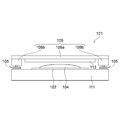
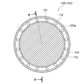
- FIG. 2 is a front view schematically showing main components of the coating apparatus 101 shown in FIG. 3 is a bottom view of the pad portion 114 of the coating apparatus 101 shown in FIG. 1
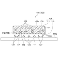
- FIG. 4 is a cross-sectional view of the pad portion 114 taken along line IV-IV in FIG.
- the support portion 109b and the side support air bearing device 107 attached to the support portion 109b shown in FIG. 1 are omitted for clarity of the drawing.
- the coating apparatus 101 of the embodiment mainly applies a resist solution 104 by a slot nozzle 113 that constitutes a coating means for applying a resist solution 104 that is a coating solution to a glass substrate 102 that is a member to be coated, and the slot nozzle 113.
- a platen 111 having a coating region 112a on which the glass substrate 102 is placed, and an air bearing device 103 for discharging a gas to float the slot nozzle 113 at a predetermined distance from the platen 111;
- An airflow control unit that controls the flow direction of the gas ejected from the air bearing device 103 and prevents the gas from entering the application region 112a.
- the surface plate 111 has a rectangular parallelepiped shape, and the flat upper surface 111a includes a rectangular application region 112a in a plan view, and a support region 112b that is disposed across the application region 112a in the short direction of the upper surface 111a.
- the application area 112a is an area where the glass substrate 102 placed on the upper surface 111a of the surface plate 111 is applied by the slit nozzle 113, and the support area 112b is the pad portion 114 of the upper surface support air bearing device 105. It is a moving area.
- the upper surface 111a of the surface plate 111 of the present embodiment is separated into the coating region 112a and the support region 112b by the boundary groove 153 extending in the longitudinal direction of the surface plate 111, but the surface plate without the boundary groove 153 is used. Needless to say, it can also be used.
- the gantry 109 includes a horizontal holding portion 109 a on which the slot nozzle 113 is mounted and two support portions 109 b that are continuous to both ends in the longitudinal direction of the horizontal holding portion 109 a, and is fixed by the upper surface support air bearing device 105. It is supported without contacting the upper surface 111a of the board 111.
- Each support portion 109b extends in a direction perpendicular to the horizontal holding portion 109a.
- One end portion of each support portion 109b is connected to one end portion of the horizontal holding portion 109a, and the other end portion of each support portion 109b. Is coupled to the side support air bearing device 107.
- a pedestal portion 109c is attached to a corner defined by the horizontal holding portion 109a and the support portion 109b, and the pedestal portion 109c is padded to the upper surface support bearing 105 via a conventionally known ball joint (not shown). Supported by the portion 114.
- the gantry 109 is levitated at a predetermined distance from the upper surface 111a and the side surface 111b of the surface plate 111 by the upper surface support air bearing device 105 and the side surface support air bearing device 107, and the gantry 109 The movement in the longitudinal direction of the 109 horizontal holding portions 109 a is regulated by the side support air bearing device 107.
- the upper surface support air bearing device 105 and the side surface support air bearing device 107 of the air bearing device 103 used in the coating apparatus 101 are a gas supply source such as a compressor that supplies compressed gas to the air bearing device 103 ( (Not shown) and pad portions 114 and 116, and a predetermined amount and a predetermined pressure of compressed gas are supplied from the gas supply source to the porous body 115 by the drive signal from the control section 131. A levitation force is applied to the pad portions 114 and 116 by discharging compressed gas from the pores provided.
- the upper surface support air bearing device 105 and the side surface support air bearing device 107 have the same configuration except for the pad portions 114 and 116. Therefore, the air bearing device 103 will be described using the upper surface support air bearing device 105.
- the pad portion 114 has a circular shape in a bottom view, and the hatched portion is a region where a jet port is provided, and is composed of a porous body 115.
- the porous body 115 is a disk-shaped member having pores communicating with each other for ejecting gas.
- a gas supply source (not shown) communicates with the pores of the porous body 115 via an air supply path 117 formed inside the pad portion 114, and the gas 123 supplied from the gas supply source is porous. By discharging from the pores of the material body 115, the pad portion 114 floats from the upper surface 111 a of the surface plate 111.
- the pad unit 114 includes an exhaust path 118 which is an air flow control means for controlling the flow direction of the jetted gas and preventing the gas from entering the coating region 112a.
- the exhaust path 118 includes an exhaust groove 119 and an exhaust through path 121.
- the exhaust groove 119 is on the bearing surface 103a of the pad portion 114 facing the upper surface 111a of the surface plate 111, and is concentric with the bearing surface 103a so as to completely surround the porous body 115 on the outer peripheral side of the porous body 115. Are continuously engraved in a ring shape.
- the exhaust groove 119 communicates with one end of an exhaust through passage 121 having a predetermined diameter and penetrating the pad portion 114, and the other end of the exhaust through passage 121 communicates with the outside of the pad portion 114 (atmospheric communication). ing.
- a plurality of exhaust through passages 121 are arranged spaced apart from each other at equal intervals along the circumferential direction of the bearing surface 103a, and in the thickness direction of the pad portion 114 (the direction intersecting the paper surface of FIG. 3, the vertical direction of FIG. 4). It is extended.
- the cross-sectional shape of the exhaust groove 119 (the cross-sectional shape along the vertical plane passing through the center of the bearing surface 103a) is a quadrangle, but various shapes such as a circle, an ellipse, and a polygon can be used. It goes without saying that you can do it.
- the exhaust groove 119 does not need to be annular as long as it is continuous, and may have a form that completely surrounds the porous body 115 (or the pores constituting the discharge port), such as a rectangle or a zigzag shape. If applicable. Furthermore, the number and shape of the exhaust through passage 121 can be changed as appropriate.
- the upper surface support air bearing device 105 configured as described above receives a drive signal from the control unit 131, compressed gas is supplied to the pad unit 114 from a gas supply source.
- the gas (reference numeral 123 in FIG. 4) supplied to the pad portion 114 passes through the air supply path 117 and is discharged from the pores of the porous body 115 (reference numeral 125 in FIG. 4), and is applied to the upper surface 111a of the surface plate 111. Colliding and applying levitation force to the pad portion 114.
- the gas discharged from the porous body 115 passes through a relatively narrow space between the bearing surface 103a and the upper surface 111a of the surface plate 111 and reaches the exhaust groove 119.
- the gas (reference numeral 127 in FIG. 4) that has reached the exhaust groove 119 enters the exhaust through passage 121 via the exhaust groove 119 and is finally the anti-bearing that is the upper surface facing the bearing surface 103a of the pad portion 114. It is discharged from the surface 103b to the outside.
- the pad portion 116 of the side support air bearing device 107 is not provided with an exhaust path (that is, an exhaust groove and an exhaust through path).
- an exhaust path that is, an exhaust groove and an exhaust through path.
- the gas supplied to the side support air bearing device 107 may affect the coating film on the glass substrate 102 on the upper surface 111 a of the surface plate 111, the exhaust gas is exhausted in the same manner as the upper surface support air bearing device 105.
- a configuration in which a groove and an exhaust through-passage are provided is also possible.
- the coating apparatus 101 is supplied with a gas having a predetermined pressure (that is, compressed gas) from the compressed gas source to the upper surface support air bearing device 105 and the side surface support air bearing device 107 in accordance with a drive signal from the control unit 131. Then, the compressed gas is discharged from the pores of the porous body 115, and the gantry 109 is supported in a state of being separated from the upper surface 111a and the side surface 111b of the surface plate 111 by a predetermined distance.
- a gas having a predetermined pressure that is, compressed gas
- the gantry 109 is scanned and moved relative to the glass substrate 102 by a driving means (not shown), A resist solution 104 is applied from the nozzle 113.
- the gas discharged from the pores of the porous body 115 collides with the support region 112b of the upper surface 111a of the surface plate 111 (reference numeral 125 in FIG. 4) to generate a levitation force. After that, it flows in the outer peripheral direction of the bearing surface 103a and further reaches the exhaust groove 119 (reference numeral 127 in FIG. 4).
- the gas 128 that has entered the exhaust groove 119 is discharged from the opposite bearing surface 103 b of the pad portion 114 to the outside through the exhaust through hole 121. Therefore, it is possible to eliminate the influence of the gas discharged from the bearing surface 103a such that the resist solution 104 on the glass substrate 102 is partially dried or blown off.
- the exhaust groove 119 has a closed shape surrounding the porous body 115 (or the pores constituting the discharge port). However, it is not always necessary to completely surround the porous body 115 (or the discharge port). It is also possible to extend so as to partially enclose the pores constituting the. That is, for example, an exhaust groove 119 may be provided at a position where the discharged gas can be prevented from entering the application region 112a on which the object is placed, such as an arc shape or a zigzag shape. Further, the bearing surface 103a of the pad portion 114 is not limited to a circle, and various shapes such as an ellipse and a polygon can be employed.
- the exhaust groove 119 of the present embodiment is configured by a continuous arc-shaped (that is, circular) groove having a single radius of curvature. It is also possible to comprise a groove extending in the direction. Moreover, it is also possible to comprise an exhaust groove from a plurality of grooves extending linearly.
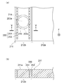
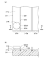
- FIG. 5A is a plan view showing a part of the surface plate 211 of the coating apparatus according to the second embodiment, showing the relationship between the surface plate 211 and the pad portion 214
- FIG. 4 is a cross-sectional view taken along line IV-IV in FIG.
- the configuration of elements that are not particularly mentioned in the coating apparatus and the modifications thereof are the same as those of the coating apparatus according to the first embodiment, and are therefore omitted.
- the pad portion 214 is indicated by a two-dot chain line.
- the coating apparatus of 2nd Embodiment is the structure provided with the exhaust path 250 which is an airflow control means in the surface plate 211 which is a mounting object.
- An exhaust path 250 is provided in the support region 212 b of the surface plate 211 that faces the bearing surface 203 a of the pad portion 214. That is, the horizontal projection position of the porous body 215 of the pad portion 214, which is horizontally projected onto the upper surface 211a of the surface plate 211, is not overlapped with the porous body 215 and is disposed within the outer periphery 203b of the bearing surface 203a. It is formed.
- the horizontal projection position means the position of the member when the coating device is viewed in the Z direction (direction intersecting the paper surface of FIG. 5A).
- the exhaust groove 251 constituting the exhaust path 250 has two linear regions that are arranged at a predetermined distance from each other in plan view. Further, the plurality of exhaust through passages 253 constituting the exhaust passage 250 communicate with the exhaust groove 251, are spaced apart from each other, and pass through the surface plate 211. As in the first embodiment, the exhaust passage 253 communicates with the outside of the surface plate 211, that is, the outside of the coating apparatus 201 at a position that does not affect the coating liquid (see the reference numeral 104 in FIG. 1). is doing.
- the airflow control means of the second embodiment is configured to be provided on the surface plate 211, but has an exhaust groove (see reference numeral 119 in FIG. 3) as in the first embodiment. It is also possible to adopt a configuration in which only the exhaust passage 253 is provided without providing the exhaust groove 251.
- FIG. 6A is a plan view showing a part of the surface plate 311 of the coating apparatus according to the second embodiment, showing the relationship between the surface plate 311 and the pad portion 314, and FIG. FIG. 6A is a cross-sectional view taken along line VI-VI in FIG.
- FIGS. 6A and 6B show only the pad portion 314 disposed on one side (left side) of the upper surface support air bearing device.
- the coating apparatus according to the third embodiment includes a partition member 351 as airflow control means. Unlike the first and second embodiments, the bearing surface of the pad portion has a discharge port composed of a porous body, but does not have an exhaust path.
- the airflow control means includes a partition member 351 for preventing the gas discharged from the pad portion 314 from flowing from the support region 312b to the application region 312a.
- the partition member 351 is disposed along a boundary groove 353 that forms a boundary between the application region 312a on the upper surface 311a of the surface plate 311 that is a placement object and the support region 312b through which the pad portion 314 passes.
- One end of the partition member 351 is fixed in a boundary groove 353 provided on the upper surface 311 a of the surface plate 311, and the pad portion 314 floats from the upper surface 311 a of the surface plate 311 at the other end of the partition member 351.
- the pad portion 314 is dimensioned so as to be in contact with the outer peripheral surface 303c. That is, in the front view of FIG. 6B, the application region 312 a side of the floating space S between the pad portion 314 of the air bearing device and the upper surface 311 a of the surface plate 311 is closed.
- the partition member 351 can be comprised from resin or the flexible member made from rubber
- an exhaust through-passage is provided on the surface plate, and the exhaust is performed in the direction of the floor surface on which the coating apparatus is disposed. Therefore, when the coating apparatus is used in a clean room, even when a downflow airflow is formed in the cleanroom, the airflow can be prevented from being disturbed.
- the gas is discharged from the exhaust path communicating with the atmosphere, but the suction means such as a pump for supplying negative pressure is connected to the exhaust path. It is also possible. By controlling the gas supply means and the suction means by the control means, it is possible to efficiently prevent the gas ejected from the air bearing device from interfering with the coating liquid landed on the coating object.
- the object to be coated is supported in a non-contact manner, but the present invention is not limited to this structure.
- the effects and operations of the present invention can be achieved even with a coating apparatus that is placed in a state in which a glass substrate is adsorbed or brought into contact with a surface plate.
- the airflow control means according to the first to third embodiments can be appropriately combined.
- the porous body is used for the ejection port for discharging the gas.
- the ejection port is configured by engraving fine holes in the plate member. It is also possible to do.
- the surface plates 111, 211, and 311 having an application region are used as the mounting object, but the mounting object of the present invention is not limited to the surface plate.
- Various platforms having a flat surface having a predetermined flatness for use in application work, measurement work, etc., and having a predetermined rigidity, hardness, and wear resistance can be used as a mounting object.
- As the surface plate a cast iron box-type surface plate, a JIS surface plate, a stone surface plate, or the like can be used.
- the air bearing device of the present invention can be applied not only to a coating device but also to a device for supporting a supported object in a non-contact manner, and it goes without saying that the applied device exhibits the effects and functions of the present invention.
Landscapes
- Engineering & Computer Science (AREA)
- General Engineering & Computer Science (AREA)
- Mechanical Engineering (AREA)
- Magnetic Bearings And Hydrostatic Bearings (AREA)
- Coating Apparatus (AREA)
- Exposure Of Semiconductors, Excluding Electron Or Ion Beam Exposure (AREA)
- Details Or Accessories Of Spraying Plant Or Apparatus (AREA)
- Spray Control Apparatus (AREA)
Abstract
厚さ精度や平坦精度を高めることができるエアベアリング装置及び当該エアベアリング装置を備える塗布装置を提供する。気体を吐出することによる浮上力により浮上するパッド部を備え、前記パッド部は、気体を吐出するための噴出口が設けられるベアリング面と、前記噴出口から吐出される気体の流れ方向を制御する気流制御手段と、を有することを特徴とするエアベアリング装置及び当該エアベアリング装置を備える塗布装置。
Description
本発明は、エアベアリング装置及び当該エアベアリング装置を備える塗布装置に関し、より具体的には、吐出される気体の流れを制御可能なエアベアリング装置及び当該エアベアリング装置を備える塗布装置に関する。
従来より、液晶パネルや半導体素子等の製造工程では、ガラス基板や半導体ウエハといった薄板状の被塗布物に、レジスト液等の塗液を塗布する塗布装置が用いられ、当該塗布装置にエアベアリング装置が利用されている。
例えば、特許文献1に開示される塗布装置は、塗液を塗布するノズルと、被塗布物が載置される直方体状の定盤と、定盤の短手方向に横切る状態でノズルが装着されるガントリと、を備え、ガントリを構成する保持部材が、定盤に対してエアベアリングにより、非接触で支持されている。また、塗液が塗布される被塗布物は、真空引き吸着により定盤に固定される。上記構成の塗布装置において、定盤上に固定されている被塗布物に対してガントリを相対移動させることでノズルを走査するとともに、ノズルから塗液を吐出し被塗布物の表面に塗布する。
ところで、近年、製品の小型化の要求に伴い、液晶パネルの厚さを薄くすること(薄厚化)や半導体素子の微細化が望まれている。しかし、従来のエアベアリング装置において浮上させるために吐出される気体は、現状の製品仕様の製造条件下における使用条件では問題とならないが、製品に対する更なる小型化の要求に応えられない恐れがある。また、従来のエアベアリング装置を用いた塗布装置で確保できる塗膜の厚さ精度や平坦精度では、塗膜のさらなる薄厚化や平坦化の実現が難しく、製品の小型化の要求に応えることが困難になることが予想される。具体的には、エアベアリング装置から吐出される気体が塗液に及ぼす影響により、塗膜の厚さに関し所期の精度が得られず、塗膜の厚さ精度及び平坦精度を実現できない恐れがある。
本発明は、かかる事情に鑑みてなされたものである。すなわち、塗膜の厚さ精度や平坦精度を高めることができるエアベアリング装置及び当該エアベアリング装置を備える塗布装置を提供することを目的とする。
上述した課題を解決し、目的を達成するために、本発明のエアベアリング装置の第1の態様は、気体を吐出することによる浮上力により浮上するパッド部を備え、前記パッド部は、気体を吐出するための噴出口が設けられるベアリング面と、前記噴出口から吐出される気体の流れ方向を制御する気流制御手段と、を有する。
また、本発明のエアベアリング装置の第2の態様によれば、前記第1の態様のエアベアリング装置であって、前記気流制御手段は、前記噴出口を部分的に又は完全に取り囲むように不連続または連続して延在する前記ベアリング面に配置される排気溝を有する。
また、本発明のエアベアリング装置の第3の態様によれば、前記第2の態様のエアベアリング装置であって、前記気流制御手段は、前記排気溝に連通し前記パッド部を貫通する排気貫通路を有する。
本発明のエアベアリング装置の第4の態様によれば、前記第2又は第3の態様のエアベアリング装置であって、前記排気溝は、前記ベアリング面の平面視で円環状である。
さらに、上述した課題を解決し、目的を達成するために、本発明の塗布装置の第1の態様は、被塗布部材に塗液を塗布するための塗布手段と、前記塗布手段により塗液を塗布する際に前記被塗布部材が位置する塗布領域を有する載置物と、前記塗布手段を前記載置物から所定距離離間し浮上させるための気体を吐出するエアベアリング装置と、前記エアベアリング装置から吐出される気体の流れ方向を制御し、前記気体が前記塗布領域へ進入することを防止する気流制御手段と、を備える。
また、本発明の塗布装置の第2の態様によれば、前記第1の態様の塗布装置であって、前記気流制御手段は、前記エアベアリング装置及び前記載置物の少なくとも一方に設けられ、前記エアベアリング装置から吐出された気体を排出するための排気経路である。
また、本発明の塗布装置の第3の態様によれば、前記第2の態様の塗布装置であって、当該塗布装置に用いられる前記エアベアリング装置は、前記気体を吐出する噴出口を備え、前記排気経路は、前記噴出口を部分的に又は完全に取り囲むように不連続または連続して延在する排気溝を有する。
また、本発明の塗布装置の第4の態様によれば、前記第2又は第3の態様の塗布装置であって、前記排気経路は、前記エアベアリング装置及び前記載置物の少なくとも一方を貫通する排気貫通路を有する。
また、本発明の塗布装置の第5の態様によれば、前記第4の態様の塗布装置であって、前記排気溝は、前記排気貫通路に連通している。
また、本発明の塗布装置の第6の態様によれば、前記第2~第4の態様の一の塗布装置であって、前記排気経路は、前記排気経路に負圧を供給できる吸引手段に連結されている。
また、本発明の塗布装置の第7の態様によれば、前記第1の態様の塗布装置であって、前記気流制御手段は、前記エアベアリング装置及び前記載置物の少なくとも一方に設けられ、前記エアベアリング装置及び前記載置物の少なくとも他方に当接するように延在する隔壁部材であり、前記隔壁部材により、前記エアベアリング装置と前記載置物との間の浮上空間は、正面視において前記塗布領域側が閉じている。
本発明にかかるエアベアリング装置は、エアベアリング装置から吐出される気体の流れを気流制御手段により制御できるので、当該エアベアリング装置の周辺物に対する吐出される気体の影響を防止することができる。さらに、本発明にかかる塗布装置の気流制御手段により、被塗布物に形成される塗膜に対する、吐出気体の影響を排除することができる。よって、塗膜の厚さ精度及び平坦精度を高めることができ、塗膜の薄厚化及び平坦化、ひいては製品の小型化を実現できる。
以下に、本発明に係るエアベアリング装置及び塗布装置の実施形態について図面を参照しつつ説明する。なお、この実施形態により本発明が限定されるものではない。
〔第1の実施形態〕
図1は、実施形態に係る塗布装置101の一部を模式的に示す斜視図であり、図2は、図1に示す塗布装置101の主要な構成要素を模式的に示す正面図であり、図3は、図1に示す塗布装置101のパッド部114の下面図であり、図4は、図3の線IV-IVに沿ったパッド部114の断面図である。なお、図2において、図1に示される支持部109b及び支持部109bに装着される側面支持エアベアリング装置107は、図面の明瞭化のため割愛されている。
図1は、実施形態に係る塗布装置101の一部を模式的に示す斜視図であり、図2は、図1に示す塗布装置101の主要な構成要素を模式的に示す正面図であり、図3は、図1に示す塗布装置101のパッド部114の下面図であり、図4は、図3の線IV-IVに沿ったパッド部114の断面図である。なお、図2において、図1に示される支持部109b及び支持部109bに装着される側面支持エアベアリング装置107は、図面の明瞭化のため割愛されている。
実施形態の塗布装置101は、主として、被塗布部材であるガラス基板102に塗液であるレジスト液104を塗布するための塗布手段を構成するスロットノズル113と、スロットノズル113によりレジスト液104を塗布する際にガラス基板102が配置される塗布領域112aを有する載置物である定盤111と、スロットノズル113を定盤111から所定距離離間し浮上させるための気体を吐出するエアベアリング装置103と、エアベアリング装置103から噴出される気体の流れ方向を制御し、気体が塗布領域112aへ進入することを防止する後述する気流制御手段と、を備える。
定盤111は直方体形状であり、その平坦な上面111aは、平面視で矩形状の塗布領域112aと、上面111aの短手方向に関し塗布領域112aを挟んで配置される支持領域112bと、を有する。塗布領域112aは、定盤111の上面111aに載置されるガラス基板102に対してスリットノズル113により塗布が行われる領域であり、支持領域112bは、上面支持エアベアリング装置105のパッド部114が移動する領域である。なお、本実施形態の定盤111の上面111aは、定盤111の長手方向に延びる境界溝153により塗布領域112aと支持領域112bとに分離されているが、境界溝153を備えない定盤を用いることも可能であることは言うまでもない。
ガントリ109は、スロットノズル113が装着されている水平保持部109aと、水平保持部109aの長手方向の両端部それぞれに連続する2つの支持部109bと、を備え、上面支持エアベアリング装置105により定盤111の上面111aに接触せずに支持される。また、各支持部109bは、水平保持部109aに対して垂直方向に延在し、各支持部109bの一端部は、水平保持部109aの一端部に連結され、各支持部109bの他端部は、側面支持エアベアリング装置107に連結される。
また、水平保持部109aと支持部109bにより画成される隅部には、台座部109cが装着され、台座部109cが従来より知られるボールジョイント(不図示)を介して上面支持ベアリング105のパッド部114に支持されている。このように、ガントリ109は、上面支持エアベアリング装置105及び側面支持エアベアリング装置107により、定盤111の上面111a及び側面111bから所定距離離間し浮上するともに、定盤111の短手方向(ガントリ109の水平保持部109aの長手方向)に関する移動は、側面支持エアベアリング装置107により規制されている。
本実施形態に係る塗布装置101に利用されているエアベアリング装置103の上面支持エアベアリング装置105及び側面支持エアベアリング装置107は、圧縮気体をエアベアリング装置103に供給するコンプレッサ等の気体供給源(不図示)と、パッド部114、116と、を備え、制御部131からの駆動信号により、所定量及び所定圧力の圧縮気体が気体供給源から多孔質体115へ供給され、多孔質体115が具備する細孔から圧縮気体を吐出させることにより、パッド部114、116に浮上力を付与する。なお、上面支持エアベアリング装置105、側面支持エアベアリング装置107は、パッド部114、116を除き同じ構成である。従って、エアベアリング装置103に関し、上面支持エアベアリング装置105を用いて説明する。
パッド部114は、図3に示されるように下面視において円形状であり、斜線部は、噴出口が設けられている領域であり、多孔質体115から構成される。多孔質体115は、気体を噴出させるための互いに連通する細孔を有する円盤状の部材である。また、不図示の気体供給源が、パッド部114の内部に形成されているエア供給路117を介して多孔質体115の細孔に連通し、気体供給源から供給される気体123が、多孔質体115の細孔から吐出することによりパッド部114が、定盤111の上面111aから浮上する。
パッド部114は、噴出する気体の流れ方向を制御し、気体が塗布領域112aへ進入することを防止する気流制御手段である排気経路118を備えている。排気経路118は、排気溝119及び排気貫通路121を有する。排気溝119は、定盤111の上面111aに対向するパッド部114のベアリング面103a上にあって、多孔質体115を多孔質体115の外周側で完全に取り囲むように、ベアリング面103aと同心に環状に連続して刻設されている。
排気溝119には、所定の径を有しパッド部114を貫通する排気貫通路121の一端部が連通し、排気貫通路121の他端部はパッド部114の外部に連通(大気連通)している。排気貫通路121は、ベアリング面103aの周方向に沿って等間隔に互いに離間して複数配置され、パッド部114の厚さ方向(図3の紙面に交差する方向、図4の上下方向)に延在している。また、図4に示すように排気溝119の断面形状(ベアリング面103aの中心を通る鉛直面に沿った断面形状)は、四角形としているが、円形、楕円形、多角形等の種々の形状とすることができることは言うまでもない。
また、排気溝119は、連続したものであれば、環状である必要はなく、矩形、ジグザグ形状等、多孔質体115(若しくは吐出口を構成する細孔)を完全に取り囲むような形態であれば適用可能である。さらに、排気貫通路121の数や形状も適宜変更可能である。
上記構成の上面支持エアベアリング装置105が、制御部131から駆動信号を受けると、気体供給源から圧縮気体がパッド部114に供給される。パッド部114に供給された気体(図4の参照符号123)は、エア供給路117を通り多孔質体115の細孔から吐出され(図4の参照符号125)、定盤111の上面111aに衝突しパッド部114に浮上力を付与する。
多孔質体115から吐出した気体(図4の参照符号125)は、ベアリング面103aと定盤111の上面111aとの間の比較的狭い空間を通り、排気溝119へと到達する。排気溝119へ到達した気体(図4の参照符号127)は、排気溝119を介して排気貫通路121へと進入し、最終的にパッド部114のベアリング面103aに対向する上面である反ベアリング面103bから外部へ排出される。
一方、側面支持エアベアリング装置107のパッド部116には、排気経路(すなわち排気溝及び排気貫通路)は設けられていない。しかし、側面支持エアベアリング装置107に供給される気体により、定盤111の上面111a上のガラス基板102上の塗膜に影響する恐れがある場合には、上面支持エアベアリング装置105と同様に排気溝及び排気貫通路を設ける構成とすることも可能である。
以上の構成において、塗布装置101は、制御部131からの駆動信号により、圧縮気体源から所定圧力の気体(すなわち圧縮気体)が、上面支持エアベアリング装置105及び側面支持エアベアリング装置107に供給されると、圧縮気体が多孔質体115の細孔から吐出し、ガントリ109が、定盤111の上面111a及び側面111bから所定距離離れた状態で支持される。ガラス基板102は、不図示の搬送手段により、定盤111の上面111aの塗布領域112aに載置されると、不図示の駆動手段によりガントリ109が、ガラス基板102に対して走査移動し、スリットノズル113からレジスト液104が塗布される。
スリットノズル113が走査移動する際、多孔質体115の細孔から吐出されている気体は、定盤111の上面111aの支持領域112bに衝突し(図4の参照符号125)浮上力を発生させた後、ベアリング面103aの外周方向へ流れ、さらに排気溝119へ到達する(図4の参照符号127)。排気溝119内へ進入した気体128は、排気貫通穴121を介してパッド部114の反ベアリング面103bから外部へ排出される。従って、ガラス基板102上のレジスト液104が、部分的に乾燥したり、又は飛ばされたりといった、ベアリング面103aから吐出される気体による影響を排除することがきる。
なお、上記実施形態では、排気溝119が多孔質体115(若しくは吐出口を構成する細孔)を取り囲む閉じた形状であるが、必ずしも完全に取り囲む必要はなく、多孔質体115(若しくは吐出口を構成する細孔)を部分的に取り囲むように延在することも可能である。すなわち、例えば、円弧状、ジグザグ状等、吐出される気体が、被塗布物を載置する塗布領域112aへ進入することを防ぐことができる位置に、排気溝119を設ける構成であればよい。また、パッド部114のベアリング面103aも円形に限定されず、楕円形、多角形等、種々の形状を採用することが可能である。また、本実施形態の排気溝119は、単一の曲率半径を有し連続する円弧状(すなわち円形)の溝から構成されているが、曲率半径が同一又は異なる複数の円弧状で、不連続に延在する溝から構成することも可能である。また、直線状に延在する複数の溝から排気溝を構成することも可能である。
〔第2の実施形態〕
次に第2の実施形態に係る塗布装置について、図5(a)、(b)を参照しつつ説明する。図5(a)は、第2の実施形態に係る塗布装置の定盤211の一部を示す平面図であり、定盤211とパッド部214との関係を示し、(b)は、図5(a)の線IV-IVに沿った断面図である。なお、以下の説明において、塗布装置の特に言及しない要素の構成及びその変形態様は、第1の実施形態に係る塗布装置と同じであるので割愛する。また、図5(a)には、エアベアリング装置のパッド部214と定盤211との関係を示すため、パッド部214が2点鎖線で示されている。
次に第2の実施形態に係る塗布装置について、図5(a)、(b)を参照しつつ説明する。図5(a)は、第2の実施形態に係る塗布装置の定盤211の一部を示す平面図であり、定盤211とパッド部214との関係を示し、(b)は、図5(a)の線IV-IVに沿った断面図である。なお、以下の説明において、塗布装置の特に言及しない要素の構成及びその変形態様は、第1の実施形態に係る塗布装置と同じであるので割愛する。また、図5(a)には、エアベアリング装置のパッド部214と定盤211との関係を示すため、パッド部214が2点鎖線で示されている。
第2の実施形態の塗布装置は、気流制御手段である排気経路250を載置物である定盤211に備える構成である。パッド部214のベアリング面203aが対向する定盤211の支持領域212b内に、排気経路250が設けられている。すなわち、定盤211の上面211a上へ水平投影した、パッド部214の多孔質体215の水平投影位置が、多孔質体215に重ならず、ベアリング面203aの外周203b内に配置されるように形成される。ここで、水平投影位置とは、塗布装置をZ方向(図5(a)の紙面に交差する方向)に視る際の部材の位置を意味する。
排気経路250を構成する排気溝251は、平面視において、互いに所定距離離れて配置される、2つの直線状の領域を有す。さらに、排気経路250を構成する複数の排気貫通路253は、排気溝251に連通し、互いに離間配置され、定盤211を貫通する。第1の実施形態と同様に、排気貫通路253は、塗液(図1の添付符号104を参照。)に影響を及ぼさない位置で、定盤211の外部、すなわち塗布装置201の外部と連通している。
上記第2の実施形態の気流制御手段は、定盤211に設ける構成としたが、第1の実施形態と同様に排気溝(図3の参照符号119参照。)を備え、定盤211には、排気溝251を設けずに、排気貫通路253のみを設ける構成とすることも可能である。
〔第3の実施形態〕
次に第3の実施形態に係る塗布装置について、図6(a)、(b)を参照しつつ説明する。図6(a)は、第2の実施形態に係る塗布装置の定盤311の一部を示す平面図であり、定盤311とパッド部314との関係を示し、(b)は、図6(a)の線VI-VIに沿った断面図である。なお、以下の説明において、塗布装置の特に言及しない要素の構成及び変形態様は、第1の実施形態に係る塗布装置と同じであるので割愛する。また、図6(a)、(b)には、上面支持エアベアリング装置の一方(左側)に配置されているパッド部314のみを図示している。
次に第3の実施形態に係る塗布装置について、図6(a)、(b)を参照しつつ説明する。図6(a)は、第2の実施形態に係る塗布装置の定盤311の一部を示す平面図であり、定盤311とパッド部314との関係を示し、(b)は、図6(a)の線VI-VIに沿った断面図である。なお、以下の説明において、塗布装置の特に言及しない要素の構成及び変形態様は、第1の実施形態に係る塗布装置と同じであるので割愛する。また、図6(a)、(b)には、上面支持エアベアリング装置の一方(左側)に配置されているパッド部314のみを図示している。
第3の実施形態に係る塗布装置は、気流制御手段として隔壁部材351を備える。パッド部のベアリング面には、多孔質体から構成される吐出口を有するが、第1及び第2の実施形態と異なり、排気経路を備えない。
気流制御手段は、パッド部314から吐出される気体が、支持領域312bから塗布領域312aへ流れることを阻止するための隔壁部材351から構成される。また、隔壁部材351は、載置物である定盤311の上面311aの塗布領域312aと、パッド部314が通る支持領域312bとの境界を構成する境界溝353に沿って配置される。
隔壁部材351の一端部は、定盤311の上面311aに設けられている境界溝353内に固定され、隔壁部材351の他端部は、パッド部314が定盤311の上面311aから浮上している状態においてパッド部314の外周面303cに接するように寸法付けされている。すなわち、図6(b)の正面視において、エアベアリング装置のパッド部314と定盤311の上面311aとの間の浮上空間Sの塗布領域312a側が閉じられることになる。
この構成により、パッド部314から吐出される気体が、塗布領域312aへ進入することを阻止することが可能である。結果として、エアベアリング装置に利用される気体が、ガラス基板上の塗布された塗液へ影響することを防止することができる。なお、隔壁部材351は、例えば、樹脂又はゴム製の可撓性部材から構成することができる。
上記した第2及び第3の実施形態では、第1の実施形態と異なり、排気貫通路を定盤に設け、塗布装置が配置される床面の方向に排気する構成である。従って、塗布装置がクリーンルーム内で使用するときに、クリーンルーム内にダウンフローの気流流れを形成している場合であっても、その気流流れを乱すことを防止できる。
上記した第1及び第2の実施形態の塗布装置では、気体の排出を、大気と連通する排気経路から行う構成であるが、負圧を供給するポンプ等の吸引手段を排気経路に連結する構成とすることも可能である。気体供給手段と吸引手段を制御手段により制御することにより、エアベアリング装置が噴出する気体が、被塗布物に着弾される塗液への干渉を効率的に防止することができる。
上記した第1乃至第3の実施形態の塗布装置では、被塗布物を非接触支持する構成であるが、本発明はこの構成に限定されない。例えば、ガラス基板を定盤に吸着させる又は接触させた状態で載置される塗布装置であっても本発明の効果及び作用を奏することは言うまでもない。さらに、第1乃至第3の実施形態に係る気流制御手段を適宜組み合わせることも可能である。
上記した第1乃至第3の実施形態では、気体を吐出する噴出口に多孔質体を用いているが、多孔質体の代わりに、板部材に細孔を刻設することにより噴出口を構成することも可能である。
上記第1乃至第3の実施形態において、塗布領域を有する定盤111、211、311が載置物として用いられているが、本発明の載置物は、当該定盤に限定されない。塗布作業、測定作業などで使用するための所定の平面度を有する平面を備え、所定の剛性、硬度、耐摩耗性を有する種々の台が載置物として利用できる。また、定盤として、鋳鉄製の箱型定盤、JIS定盤、石定盤等が利用できる。
本発明のエアベアリング装置は、塗布装置のみならず、被支持物を非接触で支持するための装置に適用でき、その適用された装置は、本発明の効果及び作用を奏することは言うまでもない。
本出願は、2012年8月6日に出願された日本特許出願2012-174198号の利益を主張するものであり、その内容は全体として参照して本明細書に援用される。
101 塗布装置
103 エアベアリング装置
103a、203a ベアリング面
105 上面支持エアベアリング装置
107 側面支持エアベアリング装置
109 ガントリ
111 定盤
111a 上面
112a 塗布領域
112b 支持領域
113 スロットノズル
114、116、214、314 パッド部
115、215 多孔質体
118 排気経路
119、251 排気溝
121、253 排気貫通路
131 制御部
351 隔壁部材
103 エアベアリング装置
103a、203a ベアリング面
105 上面支持エアベアリング装置
107 側面支持エアベアリング装置
109 ガントリ
111 定盤
111a 上面
112a 塗布領域
112b 支持領域
113 スロットノズル
114、116、214、314 パッド部
115、215 多孔質体
118 排気経路
119、251 排気溝
121、253 排気貫通路
131 制御部
351 隔壁部材
Claims (11)
- 気体を吐出することによる浮上力により浮上するパッド部を備え、
前記パッド部は、気体を吐出するための噴出口が設けられるベアリング面と、前記噴出口から吐出される気体の流れ方向を制御する気流制御手段と、を有することを特徴とするエアベアリング装置。 - 前記気流制御手段は、前記噴出口を部分的に又は完全に取り囲むように不連続または連続して延在する前記ベアリング面に配置される排気溝を有することを特徴とする請求項1に記載のエアベアリング装置。
- 前記気流制御手段は、前記排気溝に連通し前記パッド部を貫通する排気貫通路を有することを特徴とする請求項2に記載のエアベアリング装置。
- 前記排気溝は、前記ベアリング面の平面視で円環状であることを特徴とする請求項2又は3に記載のエアベアリング装置。
- 被塗布部材に塗液を塗布するための塗布手段と、
前記塗布手段により塗液を塗布する際に前記被塗布部材が位置する塗布領域を有する載置物と、
前記塗布手段を前記載置物から所定距離離間し浮上させるための気体を吐出するエアベアリング装置と、
前記エアベアリング装置から吐出される気体の流れ方向を制御し、前記気体が前記塗布領域へ進入することを防止する気流制御手段と、を備えることを特徴とする塗布装置。 - 前記気流制御手段は、前記エアベアリング装置及び前記載置物の少なくとも一方に設けられ、前記エアベアリング装置から吐出された気体を排出するための排気経路であることを特徴とする請求項5に記載の塗布装置。
- 前記エアベアリング装置は、前記気体を吐出する噴出口を備え、前記排気経路は、前記噴出口を部分的に又は完全に取り囲むように不連続または連続して延在する排気溝を有することを特徴とする請求項6に記載の塗布装置。
- 前記排気経路は、前記エアベアリング装置及び前記載置物の少なくとも一方を貫通する排気貫通路を有することを特徴とする請求項6又は請求項7に記載の塗布装置。
- 前記排気溝は、前記排気貫通路に連通していることを特徴とする請求項8に記載の塗布装置。
- 前記排気経路は、前記排気経路に負圧を供給できる吸引手段に連結されていることを特徴とする請求項6~9のいずれか一に記載の塗布装置。
- 前記気流制御手段は、前記エアベアリング装置及び前記載置物の少なくとも一方に設けられ、前記エアベアリング装置及び前記載置物の少なくとも他方に当接するように延在する隔壁部材であり、前記隔壁部材により、前記エアベアリング装置と前記載置物との間の浮上空間は、正面視において前記塗布領域側が閉じていることを特徴とする請求項5に記載の塗布装置。
Priority Applications (2)
| Application Number | Priority Date | Filing Date | Title |
|---|---|---|---|
| CN201380041409.1A CN104583618A (zh) | 2012-08-06 | 2013-06-21 | 空气轴承装置及涂布装置 |
| KR20157003630A KR20150040924A (ko) | 2012-08-06 | 2013-06-21 | 에어 베어링 장치 및 도포 장치 |
Applications Claiming Priority (2)
| Application Number | Priority Date | Filing Date | Title |
|---|---|---|---|
| JP2012174198A JP2014031865A (ja) | 2012-08-06 | 2012-08-06 | エアベアリング装置及び塗布装置 |
| JP2012-174198 | 2012-08-06 |
Publications (1)
| Publication Number | Publication Date |
|---|---|
| WO2014024583A1 true WO2014024583A1 (ja) | 2014-02-13 |
Family
ID=50067824
Family Applications (1)
| Application Number | Title | Priority Date | Filing Date |
|---|---|---|---|
| PCT/JP2013/067076 Ceased WO2014024583A1 (ja) | 2012-08-06 | 2013-06-21 | エアベアリング装置及び塗布装置 |
Country Status (5)
| Country | Link |
|---|---|
| JP (1) | JP2014031865A (ja) |
| KR (1) | KR20150040924A (ja) |
| CN (1) | CN104583618A (ja) |
| TW (1) | TW201412409A (ja) |
| WO (1) | WO2014024583A1 (ja) |
Cited By (8)
| Publication number | Priority date | Publication date | Assignee | Title |
|---|---|---|---|---|
| JPWO2015125756A1 (ja) * | 2014-02-18 | 2017-03-30 | オイレス工業株式会社 | エアベアリング装置及び測定装置 |
| US11643355B2 (en) | 2016-01-12 | 2023-05-09 | Corning Incorporated | Thin thermally and chemically strengthened glass-based articles |
| US11697617B2 (en) | 2019-08-06 | 2023-07-11 | Corning Incorporated | Glass laminate with buried stress spikes to arrest cracks and methods of making the same |
| US11795102B2 (en) | 2016-01-26 | 2023-10-24 | Corning Incorporated | Non-contact coated glass and related coating system and method |
| US11891324B2 (en) | 2014-07-31 | 2024-02-06 | Corning Incorporated | Thermally strengthened consumer electronic glass and related systems and methods |
| US12064938B2 (en) | 2019-04-23 | 2024-08-20 | Corning Incorporated | Glass laminates having determined stress profiles and methods of making the same |
| US12338159B2 (en) | 2015-07-30 | 2025-06-24 | Corning Incorporated | Thermally strengthened consumer electronic glass and related systems and methods |
| US12410090B2 (en) | 2017-11-30 | 2025-09-09 | Corning Incorporated | Non-iox glasses with high coefficient of thermal expansion and preferential fracture behavior for thermal tempering |
Families Citing this family (4)
| Publication number | Priority date | Publication date | Assignee | Title |
|---|---|---|---|---|
| EP3719443B1 (en) * | 2019-04-03 | 2021-06-09 | Hexagon Technology Center GmbH | Coordinate-measuring machine with self-cleaning air bearing |
| CN111894983A (zh) * | 2020-07-30 | 2020-11-06 | 西安工业大学 | 微孔节流的静压气体止推轴承 |
| CN114251362A (zh) * | 2020-09-24 | 2022-03-29 | 武汉科技大学 | 一种微纳多孔节流气浮球面轴承 |
| FR3139869A1 (fr) * | 2022-09-16 | 2024-03-22 | Micro-Contrôle - Spectra-Physics | Appareil pour la réduction des vibrations dans un système de régulation de mouvement à coussin d’air |
Citations (5)
| Publication number | Priority date | Publication date | Assignee | Title |
|---|---|---|---|---|
| JPS60113816A (ja) * | 1983-11-22 | 1985-06-20 | Miyoutoku:Kk | エア−スライド装置 |
| JPS62180114A (ja) * | 1986-01-31 | 1987-08-07 | Kyocera Corp | 静圧気体直線案内装置 |
| JPH09222124A (ja) * | 1996-02-19 | 1997-08-26 | Nippon Seiko Kk | 静圧気体軸受 |
| JP2001200843A (ja) * | 1999-11-22 | 2001-07-27 | Nikon Corp | 真空中で動作する流体ベアリング |
| JP2008149238A (ja) * | 2006-12-15 | 2008-07-03 | Chugai Ro Co Ltd | 塗布装置 |
Family Cites Families (5)
| Publication number | Priority date | Publication date | Assignee | Title |
|---|---|---|---|---|
| TWI222423B (en) * | 2001-12-27 | 2004-10-21 | Orbotech Ltd | System and methods for conveying and transporting levitated articles |
| JP2004019760A (ja) * | 2002-06-14 | 2004-01-22 | Nsk Ltd | 静圧軸受 |
| JP4468059B2 (ja) * | 2004-04-23 | 2010-05-26 | 太平洋セメント株式会社 | 静圧軸受け装置 |
| US7607647B2 (en) * | 2007-03-20 | 2009-10-27 | Kla-Tencor Technologies Corporation | Stabilizing a substrate using a vacuum preload air bearing chuck |
| JP2011133724A (ja) * | 2009-12-25 | 2011-07-07 | Nikon Corp | 流体静圧軸受、移動体装置、露光装置、デバイス製造方法、及び清掃装置 |
-
2012
- 2012-08-06 JP JP2012174198A patent/JP2014031865A/ja active Pending
-
2013
- 2013-06-21 WO PCT/JP2013/067076 patent/WO2014024583A1/ja not_active Ceased
- 2013-06-21 CN CN201380041409.1A patent/CN104583618A/zh active Pending
- 2013-06-21 KR KR20157003630A patent/KR20150040924A/ko not_active Withdrawn
- 2013-08-01 TW TW102127675A patent/TW201412409A/zh unknown
Patent Citations (5)
| Publication number | Priority date | Publication date | Assignee | Title |
|---|---|---|---|---|
| JPS60113816A (ja) * | 1983-11-22 | 1985-06-20 | Miyoutoku:Kk | エア−スライド装置 |
| JPS62180114A (ja) * | 1986-01-31 | 1987-08-07 | Kyocera Corp | 静圧気体直線案内装置 |
| JPH09222124A (ja) * | 1996-02-19 | 1997-08-26 | Nippon Seiko Kk | 静圧気体軸受 |
| JP2001200843A (ja) * | 1999-11-22 | 2001-07-27 | Nikon Corp | 真空中で動作する流体ベアリング |
| JP2008149238A (ja) * | 2006-12-15 | 2008-07-03 | Chugai Ro Co Ltd | 塗布装置 |
Cited By (9)
| Publication number | Priority date | Publication date | Assignee | Title |
|---|---|---|---|---|
| JPWO2015125756A1 (ja) * | 2014-02-18 | 2017-03-30 | オイレス工業株式会社 | エアベアリング装置及び測定装置 |
| US11891324B2 (en) | 2014-07-31 | 2024-02-06 | Corning Incorporated | Thermally strengthened consumer electronic glass and related systems and methods |
| US12338159B2 (en) | 2015-07-30 | 2025-06-24 | Corning Incorporated | Thermally strengthened consumer electronic glass and related systems and methods |
| US11643355B2 (en) | 2016-01-12 | 2023-05-09 | Corning Incorporated | Thin thermally and chemically strengthened glass-based articles |
| US11795102B2 (en) | 2016-01-26 | 2023-10-24 | Corning Incorporated | Non-contact coated glass and related coating system and method |
| US12410090B2 (en) | 2017-11-30 | 2025-09-09 | Corning Incorporated | Non-iox glasses with high coefficient of thermal expansion and preferential fracture behavior for thermal tempering |
| US12064938B2 (en) | 2019-04-23 | 2024-08-20 | Corning Incorporated | Glass laminates having determined stress profiles and methods of making the same |
| US11697617B2 (en) | 2019-08-06 | 2023-07-11 | Corning Incorporated | Glass laminate with buried stress spikes to arrest cracks and methods of making the same |
| US12043575B2 (en) | 2019-08-06 | 2024-07-23 | Corning Incorporated | Glass laminate with buried stress spikes to arrest cracks and methods of making the same |
Also Published As
| Publication number | Publication date |
|---|---|
| JP2014031865A (ja) | 2014-02-20 |
| KR20150040924A (ko) | 2015-04-15 |
| TW201412409A (zh) | 2014-04-01 |
| CN104583618A (zh) | 2015-04-29 |
Similar Documents
| Publication | Publication Date | Title |
|---|---|---|
| WO2014024583A1 (ja) | エアベアリング装置及び塗布装置 | |
| JP4884871B2 (ja) | 塗布方法及び塗布装置 | |
| KR101546395B1 (ko) | 이동 스테이지 | |
| JP5406852B2 (ja) | 非接触搬送装置 | |
| JP4183525B2 (ja) | 薄板の搬送用支持装置 | |
| JP2011213435A (ja) | 搬送装置及び塗布システム | |
| US20160297202A1 (en) | Liquid ejecting head, liquid ejecting apparatus, and manufacturing method of liquid ejecting head | |
| JP2023054081A (ja) | 基板を保持するための研磨ヘッドおよび基板処理装置 | |
| JP6605871B2 (ja) | 基板浮上搬送装置 | |
| JP2010245336A (ja) | 搬送方向転換装置及び浮上搬送システム | |
| JP2010254453A (ja) | 浮上装置 | |
| KR20140144236A (ko) | 반송 장치 | |
| KR100818208B1 (ko) | 부상 장치 및 반송 장치 | |
| KR102782195B1 (ko) | 기판 처리 장치 및 방법 | |
| CN109760418B (zh) | 搬运台和使用该搬运台的喷墨装置 | |
| JP2004172321A (ja) | ワーク搬送テーブル、ワーク搬送装置、液滴吐出装置、電気光学装置、電気光学装置の製造方法および電子機器 | |
| JP2014107318A (ja) | 基板保持装置、液滴吐出装置 | |
| KR102390540B1 (ko) | 디스플레이 패널용 비접촉 이송장치 | |
| JP5848812B1 (ja) | 吸着装置、及び、吸着装置の制御方法 | |
| KR20140144237A (ko) | 반송 장치 | |
| WO2011129152A1 (ja) | 旋回流形成体及び非接触搬送装置 | |
| JP6685894B2 (ja) | エアベアリング装置及び測定装置 | |
| JP2007144848A (ja) | 画像形成装置 | |
| JP4768577B2 (ja) | 非接触支持装置 | |
| JP2011230463A (ja) | 吸着装置および液滴吐出装置 |
Legal Events
| Date | Code | Title | Description |
|---|---|---|---|
| 121 | Ep: the epo has been informed by wipo that ep was designated in this application |
Ref document number: 13828469 Country of ref document: EP Kind code of ref document: A1 |
|
| NENP | Non-entry into the national phase |
Ref country code: DE |
|
| ENP | Entry into the national phase |
Ref document number: 20157003630 Country of ref document: KR Kind code of ref document: A |
|
| 122 | Ep: pct application non-entry in european phase |
Ref document number: 13828469 Country of ref document: EP Kind code of ref document: A1 |