WO2014021117A1 - 車両用の自動変速機 - Google Patents
車両用の自動変速機 Download PDFInfo
- Publication number
- WO2014021117A1 WO2014021117A1 PCT/JP2013/069573 JP2013069573W WO2014021117A1 WO 2014021117 A1 WO2014021117 A1 WO 2014021117A1 JP 2013069573 W JP2013069573 W JP 2013069573W WO 2014021117 A1 WO2014021117 A1 WO 2014021117A1
- Authority
- WO
- WIPO (PCT)
- Prior art keywords
- speed
- vehicle speed
- vehicle
- transmission
- coast stop
- Prior art date
- Legal status (The legal status is an assumption and is not a legal conclusion. Google has not performed a legal analysis and makes no representation as to the accuracy of the status listed.)
- Ceased
Links
Images




Classifications
-
- F—MECHANICAL ENGINEERING; LIGHTING; HEATING; WEAPONS; BLASTING
- F16—ENGINEERING ELEMENTS AND UNITS; GENERAL MEASURES FOR PRODUCING AND MAINTAINING EFFECTIVE FUNCTIONING OF MACHINES OR INSTALLATIONS; THERMAL INSULATION IN GENERAL
- F16H—GEARING
- F16H61/00—Control functions within control units of change-speed- or reversing-gearings for conveying rotary motion ; Control of exclusively fluid gearing, friction gearing, gearings with endless flexible members or other particular types of gearing
- F16H61/02—Control functions within control units of change-speed- or reversing-gearings for conveying rotary motion ; Control of exclusively fluid gearing, friction gearing, gearings with endless flexible members or other particular types of gearing characterised by the signals used
- F16H61/0262—Control functions within control units of change-speed- or reversing-gearings for conveying rotary motion ; Control of exclusively fluid gearing, friction gearing, gearings with endless flexible members or other particular types of gearing characterised by the signals used the signals being hydraulic
-
- F—MECHANICAL ENGINEERING; LIGHTING; HEATING; WEAPONS; BLASTING
- F16—ENGINEERING ELEMENTS AND UNITS; GENERAL MEASURES FOR PRODUCING AND MAINTAINING EFFECTIVE FUNCTIONING OF MACHINES OR INSTALLATIONS; THERMAL INSULATION IN GENERAL
- F16H—GEARING
- F16H63/00—Control outputs from the control unit to change-speed- or reversing-gearings for conveying rotary motion or to other devices than the final output mechanism
- F16H63/40—Control outputs from the control unit to change-speed- or reversing-gearings for conveying rotary motion or to other devices than the final output mechanism comprising signals other than signals for actuating the final output mechanisms
- F16H63/50—Signals to an engine or motor
-
- B—PERFORMING OPERATIONS; TRANSPORTING
- B60—VEHICLES IN GENERAL
- B60W—CONJOINT CONTROL OF VEHICLE SUB-UNITS OF DIFFERENT TYPE OR DIFFERENT FUNCTION; CONTROL SYSTEMS SPECIALLY ADAPTED FOR HYBRID VEHICLES; ROAD VEHICLE DRIVE CONTROL SYSTEMS FOR PURPOSES NOT RELATED TO THE CONTROL OF A PARTICULAR SUB-UNIT
- B60W30/00—Purposes of road vehicle drive control systems not related to the control of a particular sub-unit, e.g. of systems using conjoint control of vehicle sub-units
- B60W30/18—Propelling the vehicle
- B60W30/18009—Propelling the vehicle related to particular drive situations
- B60W30/18018—Start-stop drive, e.g. in a traffic jam
-
- F—MECHANICAL ENGINEERING; LIGHTING; HEATING; WEAPONS; BLASTING
- F16—ENGINEERING ELEMENTS AND UNITS; GENERAL MEASURES FOR PRODUCING AND MAINTAINING EFFECTIVE FUNCTIONING OF MACHINES OR INSTALLATIONS; THERMAL INSULATION IN GENERAL
- F16H—GEARING
- F16H61/00—Control functions within control units of change-speed- or reversing-gearings for conveying rotary motion ; Control of exclusively fluid gearing, friction gearing, gearings with endless flexible members or other particular types of gearing
- F16H61/0021—Generation or control of line pressure
- F16H61/0025—Supply of control fluid; Pumps therefor
- F16H61/0031—Supply of control fluid; Pumps therefor using auxiliary pumps, e.g. pump driven by a different power source than the engine
-
- B—PERFORMING OPERATIONS; TRANSPORTING
- B60—VEHICLES IN GENERAL
- B60Y—INDEXING SCHEME RELATING TO ASPECTS CROSS-CUTTING VEHICLE TECHNOLOGY
- B60Y2300/00—Purposes or special features of road vehicle drive control systems
- B60Y2300/45—Engine shutdown at standstill
-
- F—MECHANICAL ENGINEERING; LIGHTING; HEATING; WEAPONS; BLASTING
- F16—ENGINEERING ELEMENTS AND UNITS; GENERAL MEASURES FOR PRODUCING AND MAINTAINING EFFECTIVE FUNCTIONING OF MACHINES OR INSTALLATIONS; THERMAL INSULATION IN GENERAL
- F16H—GEARING
- F16H59/00—Control inputs to control units of change-speed- or reversing-gearings for conveying rotary motion
- F16H59/36—Inputs being a function of speed
- F16H59/38—Inputs being a function of speed of gearing elements
- F16H2059/385—Turbine speed
-
- F—MECHANICAL ENGINEERING; LIGHTING; HEATING; WEAPONS; BLASTING
- F16—ENGINEERING ELEMENTS AND UNITS; GENERAL MEASURES FOR PRODUCING AND MAINTAINING EFFECTIVE FUNCTIONING OF MACHINES OR INSTALLATIONS; THERMAL INSULATION IN GENERAL
- F16H—GEARING
- F16H2312/00—Driving activities
- F16H2312/14—Going to, or coming from standby operation, e.g. for engine start-stop operation at traffic lights
-
- F—MECHANICAL ENGINEERING; LIGHTING; HEATING; WEAPONS; BLASTING
- F16—ENGINEERING ELEMENTS AND UNITS; GENERAL MEASURES FOR PRODUCING AND MAINTAINING EFFECTIVE FUNCTIONING OF MACHINES OR INSTALLATIONS; THERMAL INSULATION IN GENERAL
- F16H—GEARING
- F16H61/00—Control functions within control units of change-speed- or reversing-gearings for conveying rotary motion ; Control of exclusively fluid gearing, friction gearing, gearings with endless flexible members or other particular types of gearing
- F16H61/66—Control functions within control units of change-speed- or reversing-gearings for conveying rotary motion ; Control of exclusively fluid gearing, friction gearing, gearings with endless flexible members or other particular types of gearing specially adapted for continuously variable gearings
- F16H61/662—Control functions within control units of change-speed- or reversing-gearings for conveying rotary motion ; Control of exclusively fluid gearing, friction gearing, gearings with endless flexible members or other particular types of gearing specially adapted for continuously variable gearings with endless flexible members
Definitions
- the present invention relates to an automatic transmission for a vehicle having a coast stop function.
- Patent Document 1 discloses a technique for starting a coast stop when the vehicle speed is equal to or lower than a coast stop permission vehicle speed (coast stop permission vehicle speed).
- the coast stop function is operated only in an extremely low vehicle speed region where no speed change is performed based on the vehicle speed while determining the deceleration state of the vehicle based on signals such as a brake and an accelerator opening. Yes. Since the extremely low vehicle speed region is not a shift permission region, in this extremely low vehicle speed region, the turbine rotational speed Nt is uniquely determined in the coast state, and the engagement capacity required to bring the friction engagement element into the engagement state is also unambiguous. It comes to be decided.
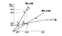
- the turbine rotation speed when the friction engagement element can be maintained in the engaged state with the hydraulic pressure that can be supplied by the electric oil pump is the turbine rotation speed indicated by Nt2 in the drawing (upper limit turbine rotation speed Nt2)
- the coast stop is performed. Since the turbine rotation speed Nt3 at the time of starting is higher than the upper limit turbine rotation speed Nt2, the frictional engagement element cannot be maintained in the engaged state.
- the upshift is started at that point, and the operating point is on the low rotational speed side (lower side in the figure) along the chain line in the figure. Change towards. Then, after that, the operating point reaches the point C on the coast line from the point G via the point H, then reaches the point D on the lowest line along the coast line, and finally along the lowest line. , Will change towards zero (0).
- the electric oil pump can be driven instead of the mechanical oil pump that stops when the engine is stopped. Since the capacity of the oil pump is smaller than that of the mechanical oil pump, a sufficient flow rate (hydraulic pressure) cannot be ensured, and the engagement state of the frictional engagement element cannot be maintained. Therefore, when there is a re-acceleration request in a state where the engagement state of the friction engagement element cannot be maintained, the friction engagement element needs to be in the engagement state. there were.
- the present invention aims to expand the coast stop area without reducing the reacceleration performance when a reacceleration request is made during execution of the coast stop.
- the present invention A fluid transmission mechanism disposed between the drive source and the drive wheel; A friction fastening element arranged in series with the fluid transmission mechanism; A hydraulic source driven by the drive source; Drive source control means for stopping the drive source when a predetermined stop condition is satisfied during deceleration of the vehicle; Another hydraulic source driven by another drive source different from the drive source while the drive source is stopped, and In the automatic transmission for a vehicle in which the friction engagement element is held in an engaged state by hydraulic pressure from the other drive source while the drive source is stopped.
- the drive source control means is configured to determine the stop of the drive source based on the output rotation speed of the fluid transmission mechanism.
- the stop of the drive source is determined in consideration of the output shaft rotational speed of the fluid transmission mechanism that contributes to the engagement of the frictional engagement element. If the vehicle speed permitting the stop of the drive source is widened to the high vehicle speed range side, even if the vehicle speed is the same, the output shaft rotation speed can vary depending on the gear ratio. When determining the stop, there is a case where the frictional engagement element cannot be held in the engaged state by the hydraulic pressure from another drive source.
- the vehicle speed permitting the stop of the drive source is set to the high vehicle speed range side Even if it is widened, it is possible to permit the drive source to stop when the frictional engagement element can be held in the engaged state by the hydraulic pressure from another drive source.
- FIG. 1 is a schematic configuration diagram of a vehicle equipped with a continuously variable transmission according to an embodiment. It is a figure explaining the structure of the controller of the continuously variable transmission concerning embodiment. It is explanatory drawing which shows an example of the shift map of the continuously variable transmission concerning embodiment. It is explanatory drawing of the hydraulic control circuit of the continuously variable transmission concerning embodiment. It is a flowchart of execution determination of the coast stop concerning embodiment. It is a shift map of the transmission concerning an embodiment. It is a timing chart explaining operation
- the “transmission ratio” of a transmission mechanism is a value obtained by dividing the input rotational speed of the transmission mechanism by the output rotational speed of the transmission mechanism.
- the “lowest speed ratio” is the maximum speed ratio of the transmission mechanism, and the “highest speed ratio” is the minimum speed ratio of the transmission mechanism.
- FIG. 1 is a schematic configuration diagram of a coast stop vehicle according to an embodiment of the present invention.
- This vehicle includes an engine 1 as a drive source, and the output rotation of the engine 1 is a torque converter 2 with a lock-up clutch, a first gear train 3, a continuously variable transmission (hereinafter simply referred to as “transmission 4”), It is transmitted to the drive wheel 7 via the second gear train 5 and the differential 6.
- the second gear train 5 is provided with a parking mechanism 8 that mechanically locks the output shaft of the transmission 4 at the time of parking.
- the transmission 4 includes a mechanical oil pump 10 m that receives rotation of the engine 1 and is driven by using a part of the power of the engine 1, and an electric oil pump 10 e that is driven by receiving power supply from the battery 13.
- the electric oil pump 10e includes an oil pump main body, an electric motor and a motor driver that rotationally drive the oil pump main body, and can control the operation load to an arbitrary load or in multiple stages.
- the transmission 4 is provided with a hydraulic control circuit 11 that regulates the hydraulic pressure (hereinafter referred to as “line pressure PL”) from the mechanical oil pump 10 m or the electric oil pump 10 e and supplies it to each part of the transmission 4. It has been.
- the transmission 4 includes a belt-type continuously variable transmission mechanism (hereinafter referred to as “variator 20”) and an auxiliary transmission mechanism 30 provided in series with the variator 20.
- “Provided in series” means that the variator 20 and the auxiliary transmission mechanism 30 are provided in series in the power transmission path from the engine 1 to the drive wheels 7.
- the auxiliary transmission mechanism 30 may be directly connected to the output shaft of the variator 20 as in this example, or may be connected via another transmission or power transmission mechanism (for example, a gear train). Alternatively, the auxiliary transmission mechanism 30 may be connected to the front stage (input shaft side) of the variator 20.
- the variator 20 includes a primary pulley 21, a secondary pulley 22, and a V-belt 23 that is wound around these.
- the primary pulley 21 and the secondary pulley 22 are each a fixed conical plate, a movable conical plate that is arranged with a sheave surface facing the fixed conical plate, and forms a V-groove between the fixed conical plate, Hydraulic cylinders 23a and 23b are provided on the back surface of the movable conical plate to displace the movable conical plate in the axial direction.
- Hydraulic cylinders 23a and 23b are provided on the back surface of the movable conical plate to displace the movable conical plate in the axial direction.
- the auxiliary transmission mechanism 30 is a transmission mechanism having two forward speeds and one reverse speed.
- the sub-transmission mechanism 30 is connected to a Ravigneaux type planetary gear mechanism 31 in which two planetary gear carriers are connected, and a plurality of friction elements connected to a plurality of rotating elements constituting the Ravigneaux type planetary gear mechanism 31 to change their linkage state.
- Fastening elements Low brake 32, High clutch 33, Rev brake 34
- the gear position of the auxiliary transmission mechanism 30 is changed.
- the gear position of the subtransmission mechanism 30 is the first speed. If the high clutch 33 is engaged and the low brake 32 and the rev brake 34 are released, the speed stage of the subtransmission mechanism 30 becomes the second speed having a smaller speed ratio than the first speed. Further, if the Rev brake 34 is engaged and the Low brake 32 and the High clutch 33 are released, the shift speed of the subtransmission mechanism 30 is reverse.
- the transmission 4 is expressed as “the transmission 4 is in the low speed mode” when the shift speed of the auxiliary transmission mechanism 30 is the first speed, and “the transmission 4 is in the high speed mode” when it is the second speed. Express.
- Each frictional engagement element is provided on the power transmission path at the front stage or the rear stage of the variator 20, and enables transmission of power to the transmission 4 when both are engaged, and disables transmission of power to the transmission 4 when released. To do.
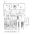
- the controller 12 is a controller that controls the engine 1 and the transmission 4 in an integrated manner. As shown in FIG. 2, the CPU 12, a storage device 122 including a RAM / ROM, an input interface 123, an output interface 124, The bus 125 interconnects these components.
- the output signal of the rotational speed sensor 42 for detecting the speed Npri
- the output signal of the vehicle speed sensor 43 for detecting the vehicle speed VSP
- the output signal of the line pressure sensor 44 for detecting the line pressure PL
- the output signal of the inhibitor switch 45, the output signal of the brake hydraulic pressure sensor 46 for detecting the brake hydraulic pressure, the output signal of the turbine rotational speed sensor 47 for detecting the rotational speed of the output shaft of the torque converter 2, and the like are input.
- the storage device 122 stores a control program for the engine 1, a shift control program for the transmission 4, and various map tables used in these programs.
- the CPU 121 reads and executes a program stored in the storage device 122, performs various arithmetic processes on various signals input via the input interface 123, and performs fuel injection amount signal, ignition timing signal, throttle opening. A degree signal, a shift control signal, and a drive signal of the electric oil pump 10e are generated, and the generated signals are output to the engine 1, the hydraulic control circuit 11, and the motor driver of the electric oil pump 10e via the output interface 124.
- Various values used in the arithmetic processing by the CPU 121 and the arithmetic results are appropriately stored in the storage device 122.
- the hydraulic control circuit 11 includes a plurality of flow paths and a plurality of hydraulic control valves.
- the hydraulic control circuit 11 controls a plurality of hydraulic control valves on the basis of the shift control signal from the controller 12 to switch the hydraulic pressure supply path, and at the same time, obtains the necessary hydraulic pressure from the hydraulic pressure generated by the mechanical oil pump 10m or the electric oil pump 10e. It is prepared and supplied to each part of the transmission 4. As a result, the gear ratio of the variator 20 and the gear position of the subtransmission mechanism 30 are changed, and the transmission 4 is shifted.
- FIG. 3 shows an example of the shift map stored in the storage device 122. Based on this shift map, the controller 12 controls the variator 20 and the subtransmission mechanism 30 according to the driving state of the vehicle (in this embodiment, the vehicle speed VSP, the primary rotational speed Npri, and the accelerator opening APO).
- the driving state of the vehicle in this embodiment, the vehicle speed VSP, the primary rotational speed Npri, and the accelerator opening APO.
- the operating point of the transmission 4 is defined by the vehicle speed VSP and the primary rotational speed Npri.
- the slope of the line connecting the operating point of the transmission 4 and the zero point of the lower left corner of the transmission map is the transmission ratio of the transmission 4 (the overall transmission ratio obtained by multiplying the transmission ratio of the variator 20 by the transmission ratio of the subtransmission mechanism 30; , Referred to as “through gear ratio”).
- a shift line is set for each accelerator opening APO, and the shift of the transmission 4 is selected according to the accelerator opening APO.
- the transmission 4 When the transmission 4 is in the low speed mode, the transmission 4 can be obtained by setting the low speed mode Low line obtained by setting the transmission ratio of the variator 20 to the lowest transmission ratio, and the low speed mode obtained by setting the transmission ratio of the variator 20 to the highest transmission ratio. The speed can be changed between the highest lines. In this case, the operating point of the transmission 4 moves in the A region and the B region.
- the transmission 4 when the transmission 4 is in the high speed mode, the transmission 4 can be obtained by setting the maximum speed line of the high speed mode obtained by setting the transmission ratio of the variator 20 as the lowest transmission ratio and the transmission ratio of the variator 20 as the highest transmission ratio. It is possible to shift between the high-speed mode highest line. In this case, the operating point of the transmission 4 moves in the B region and the C region.
- the gear ratio of each gear stage of the subtransmission mechanism 30 is such that the gear ratio corresponding to the low speed mode highest line (low speed mode maximum high gear ratio) corresponds to the gear ratio corresponding to the high speed mode lowest line (high speed mode lowest gear ratio). ) Is set to be smaller than. Accordingly, the range of the through speed ratio of the transmission 4 that can be achieved in the low speed mode (“low speed mode ratio range” in the figure) and the range of the through speed ratio of the transmission 4 that can be taken in the high speed mode (“high speed mode” in the figure).
- Ratio range partially overlaps and the operating point of the transmission 4 is in the B region sandwiched between the high-speed mode lowest line and the low-speed mode highest line, the transmission 4 is in the low-speed mode and the high-speed mode. Either mode can be selected.
- a mode switching shift line for shifting the sub-transmission mechanism 30 is set so as to overlap the low speed mode highest line.
- the through speed change ratio (hereinafter referred to as “mode change speed change ratio mRatio”) corresponding to the mode change speed change line is set to a value equal to the low speed mode highest speed change ratio.
- the reason why the mode switching shift line is set in this way is that the smaller the gear ratio of the variator 20 is, the smaller the input torque to the subtransmission mechanism 30 is, so that a shift shock when shifting the subtransmission mechanism 30 can be suppressed. .
- actual through speed ratio Ratio When the operating point of the transmission 4 crosses the mode switching speed line, that is, the actual value of the through speed ratio (hereinafter referred to as “actual through speed ratio Ratio”) changes across the mode switching speed ratio mRatio.
- the controller 12 performs the coordinated shift described below and switches between the high speed mode and the low speed mode.
- the controller 12 shifts the auxiliary transmission mechanism 30 and changes the transmission ratio of the variator 20 in a direction opposite to the direction in which the transmission ratio of the auxiliary transmission mechanism 30 changes.
- the inertia phase in which the gear ratio of the auxiliary transmission mechanism 30 actually changes and the period in which the gear ratio of the variator 20 changes are synchronized.
- the reason why the speed ratio of the variator 20 is changed in the direction opposite to the speed ratio change of the auxiliary speed change mechanism 30 is to prevent the change in the input rotation caused by the step in the actual through speed ratio Ratio from giving the driver a sense of incongruity. Because.
- the controller 12 changes the speed stage of the subtransmission mechanism 30 from the first speed to the second speed.
- the speed is changed (1-2 shift), and the gear ratio of the variator 20 is changed to Low.
- the controller 12 changes the speed stage of the subtransmission mechanism 30 from the second speed to the first speed.
- the transmission ratio of the variator 20 is changed to the High side.
- the actual through speed ratio Ratio of the transmission 4 is higher than the mode switching speed ratio mRatio. Even if it changes over the low side from the 2nd speed, the shift from the 2nd speed to the 1st speed is not performed.
- controller 12 performs coast stop control described below in order to suppress the fuel consumption.
- the coast stop control is a control that suppresses fuel consumption by automatically stopping the engine 1 (coast stop) while the vehicle is traveling in a low vehicle speed range.
- the fuel cut control executed when the accelerator is off is common in that the fuel supply to the engine 1 is stopped, but the lockup clutch is released and the power transmission path between the engine 1 and the transmission 4 is disconnected. The difference is that the rotation of the engine 1 is completely stopped. In this case, in the transmission 4 according to the embodiment, during the coast stop, the frictional engagement element (high clutch 33) is held in the engaged state until the vehicle stops.
- the controller 12 In executing the coast stop, the controller 12 first determines the following conditions a to d, for example.
- b The brake pedal is depressed (brake hydraulic pressure is greater than or equal to a predetermined value)
- Vehicle speed is a predetermined low vehicle speed (for example, 16 km / h) or less
- Turbine rotation speed is a predetermined rotation speed or less,
- conditions a to c are conditions for determining whether the driver intends to stop.
- the controller 12 determines that the coast stop condition is satisfied when the conditions a to c are all satisfied, and determines the start of the coast stop when the condition d is satisfied in addition to the conditions a to c.
- coast stop fuel supply to the engine 1 is stopped and the engine 1 is automatically stopped.
- the mechanical oil pump 10m driven by the power of the engine 1 is also stopped, and the discharge pressure is reduced to finally become zero.
- the electric oil pump 10e starts to be driven.
- the hydraulic pressure generated by the electric oil pump 10e becomes larger than the hydraulic pressure generated by the mechanical oil pump 10m
- the electric oil pump 10e The generated hydraulic pressure is supplied to the hydraulic cylinders 23 a and 23 b and the auxiliary transmission mechanism 30.
- the hydraulic pressure supplied to the hydraulic cylinders 23a and 23b changes the variator 20 to a gear ratio according to the vehicle speed at that time until the vehicle decelerates and stops.
- the controller 12 thereafter maintains the engaged state of the high clutch 33 until the vehicle stops.
- the controller 12 releases the high clutch 33 and then fastens the low brake 32 in preparation for the start of the vehicle.
- the controller 12 restarts the fuel supply to the engine 1 and restarts the engine 1, and the mechanical oil pump 10m generates sufficient hydraulic pressure. When this happens, the electric oil pump 10e is stopped.
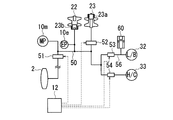
- FIG. 4 is an explanatory diagram showing the configuration of the hydraulic control circuit 11 of the present embodiment.
- the hydraulic control circuit 11 includes a mechanical oil pump 10 m that is driven by the driving force of the engine 1.
- the hydraulic pressure generated by the mechanical oil pump 10 m is adjusted to a predetermined line pressure by the pressure regulator valve 51 and is distributed to each part of the variator 20 and the subtransmission mechanism 30 via the oil passage 50.
- the hydraulic pressure generated by the mechanical oil pump 10 m is supplied to the torque converter 2 via the pressure regulator valve 51. This hydraulic pressure is used for torque transmission of the torque converter 2 and for engagement / release of the lock-up clutch.
- the line pressure of the oil passage 50 is supplied to the oil chamber of the hydraulic cylinder 23 b of the secondary pulley 22.
- the line pressure in the oil passage 50 is reduced by the pressure reducing valve 52 and supplied to the oil chamber of the hydraulic cylinder 23 a of the primary pulley 21.
- the pressure reducing valve 52 By adjusting the hydraulic pressure supplied to the oil chamber of the hydraulic cylinder 23a by the pressure reducing valve 52, the width of each V groove changes due to the differential pressure from the line pressure supplied to the oil chamber of the hydraulic cylinder 23b.
- the contact radius between the pulley 23 and the pulley changes, and the gear ratio of the variator 20 changes steplessly.
- the line pressure of the oil passage 50 is supplied to the low brake 32 via the pressure reducing valve 53 and to the high clutch 33 via the pressure reducing valve 54 in the auxiliary transmission mechanism 30.
- the pressure reducing valve 53 controls the engagement force of the Low brake 32 by adjusting the hydraulic pressure supplied to the Low brake 32.
- the pressure reducing valve 54 controls the fastening force of the high clutch 33 by adjusting the hydraulic pressure supplied to the high clutch 33.
- An accumulator 60 is connected to the oil passage 56 between the pressure reducing valve 53 and the low brake 32.
- the accumulator 60 stores hydraulic oil therein and relieves changes in the hydraulic pressure in the oil passage 56 with the hydraulic oil.
- the hydraulic oil is stored in the accumulator 60.
- the hydraulic oil stored in the accumulator 60 is supplied to the oil passage 56 to delay the response of the oil pressure reduction in the oil passage 56.
- the hydraulic oil in the oil passage 56 rises from a low state, the hydraulic oil is stored in the accumulator 60 and delays the response of the oil pressure in the oil passage 56 to rise. As a result, the response of the oil pressure in the oil passage 56 is delayed and the oil pressure is prevented from rising and falling rapidly, so that a shock at the time of engaging and releasing the Low brake 32 can be suppressed.
- the controller 12 controls the pressure regulator valve 51 to adjust the line pressure. Further, the pressure reducing valve 52 is controlled to adjust the hydraulic pressure of the primary pulley 21 to the hydraulic cylinder 23a, thereby controlling the transmission ratio of the variator 20. In addition, the pressure reducing valve 53 is controlled to control the engaged state of the Low brake 32. Further, the engagement state of the high clutch 33 is controlled by controlling the pressure reducing valve 54.
- the mechanical oil pump 10m is driven by the rotation of the engine 1. While the engine 1 is rotating, the mechanical oil pump 10 m always rotates and generates hydraulic pressure necessary for the operation of the transmission 4. Since the transmission 4 requires hydraulic pressure in preparation for the start of the vehicle even when the vehicle is stopped, the line pressure is generated by driving the mechanical oil pump 10m when the engine 1 is rotating when the vehicle is stopped.
- the oil passage 50 is provided with an electric oil pump 10e.
- the electric oil pump 10e is supplied with electric power from the battery 13 under the control of the controller 12 in order to supply hydraulic pressure to the transmission 4 when the rotation of the engine 1 is stopped and the mechanical oil pump 10m is not operating. Drive to generate hydraulic pressure.
- the electric oil pump 10e operates at a relatively low load such as an idle stop or a coast stop. Therefore, it is desirable to have a capacity that can satisfy the required hydraulic pressure in such an operating situation, and a capacity that does not increase the weight and cost of the vehicle.
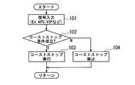
- FIG. 5 is a flowchart of coast stop execution determination by the controller 12 of the present embodiment. Note that the processing of this flowchart is executed by the controller 12 at a predetermined interval (for example, 10 ms).
- the coast stop execution determination process by the controller 12 will be described. Signals are input from the various sensors shown in FIG. 2 to the controller 12, and when signals are input from the various sensors (step 101), the current operating state specified from the input signals is obtained. Based on this, it is determined whether or not the coast stop condition is satisfied (step 102).
- the coast stop condition is a condition for determining whether or not the driver intends to stop, and is the following a to c.
- a: The foot is released from the accelerator pedal (accelerator opening APO 0)
- step 102 determines whether the coast stop condition is not satisfied. If it is determined in step 102 that the coast stop condition is not satisfied, the process proceeds to step 104 and the coast stop is prohibited (stop of the engine 1 is prohibited). The coast stop is not executed in step (b).
- step 102 when it is determined that the coast stop condition is satisfied (step 102, Yes), the process proceeds to step 103, where coast stop is permitted (stop of the engine 1 is permitted). A coast stop will be executed at.
- the predetermined rotation speed Nt2 is set to the upper limit value of the turbine rotation speed Nt when the engaged state of the high clutch 33 can be maintained by the hydraulic pressure that can be generated by the electric oil pump 10e.
- the speed Nt2) varies depending on the hydraulic pressure that can be generated by the electric oil pump 10e included in the transmission 4.
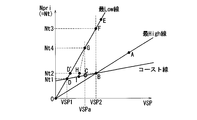
- FIG. 6 is a shift map of the transmission 4 according to the embodiment and is a view for explaining the low vehicle speed range side where the coast stop is executed.
- FIG. 7 is a timing chart for explaining the operation of the transmission 4.
- FIG. 7A shows the case of the embodiment in which the coast stop permission vehicle speed VSP2 and the turbine rotational speed Nt are taken into consideration in the determination of the start of the coast stop.
- (B) is a figure which respectively shows the case of the prior art which considers only coast stop permission vehicle speed VSP1.
- CS area means “area where coast stop is executed”.
- the coast stop permission vehicle speed VSP1 in the case of the conventional example is set in a low vehicle speed range (vehicle speed range in which the vehicle speed and the turbine rotation speed correspond one-to-one) where the turbine rotation speed Nt is uniquely determined with respect to the vehicle speed.
- the coast stop permission vehicle speed VSP2 is higher than the coast stop permission vehicle speed VSP1, and is a vehicle speed range in which the turbine rotation speed Nt is not uniquely determined with respect to the vehicle speed (the possible turbine speeds for one vehicle speed).
- a vehicle speed range having a plurality of rotational speeds Nt a vehicle speed range in which a shift can be performed is set.
- the operating point of the transmission 4 is the operating point at that point (point A) as the speed decreases.
- point B changes from point B to point C through point along the coast line, and finally changes from point D to zero (0) along the lowest line. Will change towards.
- the predetermined rotational speed Nt2 which is one of the coast stop conditions, coincides with the intersection of the highest line, coast line, and coast stop permission vehicle speed VSP2.
- the turbine rotation speed Nt at the time t2 becomes equal to or less than the predetermined rotation speed Nt2 for determining execution of the coast stop. It is determined that the stop condition is satisfied ((a) of FIG. 7: vehicle speed, turbine rotation speed Nt, coast stop reference, FIG. 5: step 102, Yes).
- the shift map in which the predetermined rotation speed Nt2 coincides with the intersection of the highest line, the coast line, and the coast stop permission vehicle speed VSP2 is exemplified.
- the predetermined rotation speed Nt2 is not necessarily limited to these intersections. There is no need to match.
- the coast stop is started at the time t2 ((a) of FIG. 7: see coast stop, FIG. 5: Step 103). Then, with the start of this coast stop as a trigger, fuel injection to the engine 1 is stopped, the engine 1 is stopped, and the electric oil pump 10e is started ((a) in FIG. 7: engine rotation) Number Ne, see electric oil pump). Therefore, when the hydraulic pressure generated by the electric oil pump 10e becomes larger than the hydraulic pressure generated by the mechanical oil pump 10m that is stopped when the engine is stopped, the hydraulic pressure from the mechanical oil pump 10m is changed to the electric oil pump. The hydraulic pressure from 10e is supplied to the subtransmission mechanism 30 and the hydraulic cylinders 23a, 23b.
- the high clutch 33 of the auxiliary transmission is maintained in the engaged state until the vehicle stops in preparation for a request for re-acceleration during the course stop. It is supposed to be.
- torque input from the upstream side of the auxiliary transmission mechanism 30 upstream torque Tu
- downstream torque Td downstream torque
- the predetermined rotational speed Nt2 that is one of the coast stop conditions described above is the upper limit of the turbine rotational speed Nt when the engaged state of the High clutch 33 can be maintained by the hydraulic pressure that can be generated by the electric oil pump 10e. Is set to a value.
- FIG. 8 is a diagram schematically showing a power transmission path from the engine to the wheels
- FIG. 9 is a diagram for explaining the difference between the upstream input torque and the downstream input torque in the frictional engagement element.
- the rotational driving force of the engine is transmitted to the wheels via the torque converter T / C of the automatic transmission and the auxiliary transmission mechanism (friction engagement element).
- the difference between the torque input from the upstream side of the friction engagement element (upstream torque Tu) and the torque input from the downstream side (downstream torque Td) The hydraulic pressure corresponding to is required.
- the downstream torque Td is a torque corresponding to the deceleration of the vehicle due to the depression of the brake, and increases as the amount of depression of the brake increases.
- the upstream torque Tu is a torque corresponding to the output rotational speed of the torque converter T / C (hereinafter referred to as the turbine rotational speed Nt), and the difference in rotational speed between the impeller I of the torque converter T / C and the turbine T. The larger the (difference), the larger.
- the turbine rotational speed Nt of the turbine T in the torque converter T / C increases in proportion to the vehicle speed because the frictional engagement element is engaged. Therefore, the upstream torque Tu increases as the vehicle speed at the coast stop increases.
- the difference between the upstream torque Tu and the downstream torque Td increases.
- the following two cases (1) When the vehicle is just before stopping. In this case, the upstream torque Tu decreases with respect to the downstream torque Td (see symbol a in FIG. 9), and the difference ( ⁇ Ta) increases.
- the turbine rotation speed Nt increases. In this case, the upstream torque Tu increases with respect to the downstream torque Td (see symbols b and c in FIG. 9), and the difference ( ⁇ Tb, ⁇ Tc) increases.
- coast stop is generally not executed at the time of sudden deceleration where the downstream torque Td becomes excessive, except for the case immediately before the vehicle stops at the time of sudden deceleration, in the case of (1) above, just before the vehicle stops (the vehicle speed is In the case of substantially zero), the upstream torque Tu is substantially zero (upstream torque Tu ⁇ 0), and the downstream torque Td ⁇ difference.
- the difference since the difference is relatively small, it is possible to maintain the engaged state of the frictional engagement element with the hydraulic pressure that can be supplied from the electric oil pump.
- a difference region in which the engagement state of the frictional engagement element can be maintained with hydraulic pressure that can be supplied from the electric oil pump that is, a low vehicle speed region where the vehicle speed is low (a vehicle speed region side lower than the vehicle speed VSP1 in FIG. 6). Coast stop was allowed only in
- the coast stop permission vehicle speed VSP2 is on the high vehicle speed region side where there are a plurality of turbine rotation speeds that can be taken for one vehicle speed (the vehicle speed VSP1 side is also on the high vehicle speed region side).
- the operation region during coast stop is a region on the straight line from zero to point D and surrounded by point B, point D, and point F.
- the upper limit value of the turbine rotation speed Nt when the engaged state of the high clutch 33 can be maintained by the hydraulic pressure that can be generated by the electric oil pump 10e is the turbine rotation speed.
- the predetermined rotational speed Nt2 is set to the upper limit value of the turbine rotational speed Nt when the engaged state of the High clutch 33 can be maintained by the hydraulic pressure that can be generated by the electric oil pump 10e, the coast stop is started. Immediately after the time t2, the high clutch 33 is maintained in the engaged state. Therefore, after time t2, the input shaft and the output shaft of the auxiliary transmission mechanism 30 decrease at the same rotational speed. (See (a) of FIG. 7: auxiliary transmission mechanism)
- the operating point of the transmission is from the operating point (point A) at that time point.
- the characteristic line High to the point B changing along the coast line from the point B to the point C to the point D, and finally along the characteristic line Low from the point D toward zero (0) Will change.
- the turbine rotation speed is not used for the determination of the start of the coast stop, and the coast stop is not executed until the vehicle speed becomes equal to or less than the coast stop permission vehicle speed VSP1. Yes. Therefore, when the vehicle is traveling at a vehicle speed higher than the coast stop permission vehicle speed VSP2, if the vehicle speed decreases due to acceleration: off, brake: on, the coast stop starts until time t3 when the vehicle speed is less than the coast stop permission vehicle speed VSP1. (Refer to FIG. 7 (b): vehicle speed, coast stop).
- the coast stop is started in the transmission 4 according to the embodiment before the transmission according to the conventional example. Therefore, in the transmission according to the embodiment, the coast stop can be executed prior to the transmission according to the conventional example by the time difference from the time t2 to the time t3 in FIG. become.
- FIG. 10 is a timing chart for explaining another example of the operation of the transmission 4.
- FIG. 10A is an embodiment in which the coast stop permission vehicle speed VSP2 and the turbine rotational speed Nt are taken into account in determining the start of the coast stop.
- (B) is a figure which shows the case of the prior art example which considers only the vehicle speed VSP2, respectively.
- “CS region” means “region where coast stop is executed”.
- the operating point of the transmission 4 is the lowest line.
- the acceleration is stopped (the accelerator is turned off) and the brake is depressed. Changes from the operating point (point E) at that time point toward zero (0) along the lowest line.
- the coast stop is started at time t3 ((a) in FIG. 10: see coast stop, FIG. 5: step 103). Then, with the start of this coast stop as a trigger, fuel injection to the engine 1 is stopped, the engine 1 is stopped, and the electric oil pump 10e is started ((a) in FIG. 10: engine rotation) Number Ne, see electric oil pump). Therefore, when the hydraulic pressure generated by the electric oil pump 10e becomes larger than the hydraulic pressure generated by the mechanical oil pump 10m that is stopped when the engine is stopped, the hydraulic pressure from the mechanical oil pump 10m is changed to the electric oil pump. The hydraulic pressure from 10e is supplied to the subtransmission mechanism 30 and the hydraulic cylinders 23a, 23b.
- the high clutch 33 of the auxiliary transmission is maintained in the engaged state until the vehicle stops in preparation for a request for re-acceleration during the coast stop. It is supposed to be.
- the torque input from the upstream side of the auxiliary transmission mechanism 30 upstream torque Tu
- a hydraulic pressure corresponding to the difference in torque (downstream torque Td) input from the downstream side is required.
- the predetermined rotational speed Nt2 that defines the start condition of the coast stop described above is the turbine rotational speed Nt when the engaged state of the High clutch 33 can be maintained by the hydraulic pressure that can be generated by the electric oil pump 10e.
- the upper limit is set. Therefore, since the engaged state of the high clutch 33 is maintained immediately after the time t3 when the coast stop is started, the input shaft and the output shaft of the auxiliary transmission mechanism 30 decrease at the same rotational speed after the time t3. I will go.
- the transmission 4 when the L range is selected by the shift lever and the gear ratio is fixed to the lowest line, when the vehicle is started and accelerated by depressing the accelerator pedal, the transmission 4 The operating point changes from zero (0) to the high vehicle speed side (right side in the figure) through point D and point D ′ along the lowest line. Then, after the vehicle speed becomes higher than the coast stop permission vehicle speed VSP2, when the operating point E is reached, the acceleration is stopped (the accelerator is turned off) and the brake is depressed. Since the gear ratio is fixed at the lowest line, the speed changes from the operating point (point E) at that time toward zero (0) along the lowest line.
- the coast stop is started at the time t2 (see FIG. 10B, vehicle speed, coast stop reference, FIG. 6: point F). reference).
- the turbine rotational speed Nt3 corresponding to the point F is higher than the upper limit rotational speed Nt2 at which the high clutch 33 of the auxiliary transmission can be held in the engaged state by the hydraulic pressure from the electric oil pump 10e.
- the high clutch 33 cannot be engaged and the slip state occurs. Therefore, the high clutch 33 slips immediately after the time t2 when the coast stop is started, and after the time t2, there is a difference between the rotational speeds of the input shaft and the output shaft of the subtransmission mechanism 30. There is a possibility that the behavior of 4 is uncomfortable.
- the vehicle speed range in which the coast stop permission vehicle speed is changed by changing the initial permission vehicle speed VSP1 from the initial permitted vehicle speed VSP1 to the vehicle speed VSP2 on the higher vehicle speed side. May be unable to maintain the engaged state of the frictional engagement element (high clutch 33) even if the torque is widened to the high vehicle speed range side.
- whether or not the coast stop can be started is determined based not only on the vehicle speed but also on the turbine rotation speed Nt. Therefore, even if the coast stop start vehicle speed is set to a higher vehicle speed side than the vehicle speed range in which the rotational speed of the turbine corresponds to the vehicle speed on a one-to-one basis, The coast stop is executed only when the turbine rotation speed is capable of maintaining the engaged state, and it is possible to prevent the driver from feeling uncomfortable at the coast stop.
- the coast stop can be started from the higher vehicle speed side than in the case of the conventional transmission, and the fuel efficiency can be improved.
- the operating point of the transmission 4 moves from zero (0) to point D and point D ′ along the lowest line toward the high vehicle speed side (right side in the figure). Will change. Then, if the accelerator pedal is released and the brake pedal is depressed when the operating point reaches point G, an upshift is started at that point, and the operating point indicates a low rotational speed along the chain line in the figure. It changes toward the side (lower side in the figure). Then, after that, the operating point reaches the point I on the coast line from the point G via the point H, then reaches the point D on the lowest line along the coast line, and finally along the lowest line. , Will change towards zero (0).
- the vehicle speed VSPa at that time is lower than the coast stop start vehicle speed VSP2 (VSPa ⁇ VSP2), but the turbine rotational speed Nt4 is the predetermined speed described above. Since the rotational speed is greater than Nt2 (Nt4> Nt2), all the coast stop conditions a to e described above are not satisfied. Therefore, the coast stop is prohibited at the time D when the accelerator pedal is released.
- the vehicle speed range for executing the coast stop is changed by changing the permitted vehicle speed of the coast stop from the original permitted vehicle speed VSP1 to the vehicle speed VSP2 on the higher vehicle speed side. If it is simply widened to the high vehicle speed side, coast stop is started at time G when the accelerator pedal is released. Then, the turbine rotational speed Nt4 at the time point G when the accelerator pedal is released is higher than the upper limit rotational speed Nt2 at which the high clutch 33 of the auxiliary transmission can be held in the engaged state by the hydraulic pressure from the electric oil pump 10e. The clutch 33 cannot be engaged, and a slip state occurs.
- the torque converter 2 (fluid transmission mechanism) disposed between the engine 1 (drive source) and the drive wheels 7; A subtransmission mechanism 30 (friction engagement element) arranged in series with the torque converter 2; A mechanical oil pump 10m (hydraulic power source) driven by the engine 1, A controller 12 (drive source control means) that stops the engine 1 when a predetermined stop condition is satisfied during deceleration of the vehicle; An electric oil pump 10e driven by the battery 13 while the engine 1 is stopped, In the automatic transmission for a vehicle in which the friction engagement element of the auxiliary transmission mechanism 30 is held in the engaged state by the hydraulic pressure from the electric oil pump 10e while the engine 1 is stopped.
- the controller 12 is configured to determine whether or not the engine 1 can be stopped based on the turbine rotation speed Nt (output shaft rotation speed) of the torque converter 2 in addition to the above stop condition.
- the frictional engagement element may not be held in the engaged state.
- the friction engagement element in consideration of the turbine rotational speed Nt that contributes to the engagement of the friction engagement element in the determination of the stop of the engine 1, for example, the friction engagement element is engaged with the hydraulic pressure from the electric oil pump 10e.
- the vehicle speed permitting the engine 1 to stop (coast stop permission vehicle speed) is set to the higher vehicle speed side. Even if it is spread out, when the engine 1 is stopped, it is possible to suitably prevent the frictional engagement element from being in a non-engaged state. This can prevent the driver from feeling uncomfortable with the behavior of the transmission 4.
- the engine 1 can be stopped even at the high vehicle speed side, the opportunity to stop the engine 1 can be increased, and an effect of improving fuel consumption can be expected.
- controller 12 is configured to permit the engine 1 to stop when the turbine rotational speed Nt is equal to or lower than a predetermined rotational speed Nt2 determined according to the hydraulic pressure that can be generated by the electric oil pump 10e.
- Whether or not the frictional engagement element can be held in the engaged state is determined according to the hydraulic pressure that can be generated by the electric oil pump 10e.
- the friction engagement element can be held in the engaged state by the hydraulic pressure from the electric oil pump 10e even if the vehicle speed permitting the stop of the engine 1 (coast stop permission vehicle speed) is widened to the high vehicle speed range side.
- the engine 1 it is possible to allow the engine 1 to stop (start coast stop).
- start coast stop since the vehicle speed which permits the stop of the engine 1 can be extended to the higher vehicle speed range side, the opportunity that the stop of the engine 1 is performed can be increased.
- the time during which the engine 1 can be stopped increases, the fuel efficiency is improved accordingly.
- the frictional engagement element can be suitably prevented from slipping, the rotational driving force of the engine 1 can be quickly transmitted from the upstream side to the downstream side of the frictional engagement element when a re-acceleration request is made. Therefore, it is possible to suitably prevent the reacceleration performance of the vehicle equipped with the automatic transmission from being lowered.
- the predetermined rotational speed Nt2 is set to the upper limit value of the turbine rotational speed Nt that can maintain the engagement state of the frictional engagement element at the hydraulic pressure that can be generated by the electric oil pump 10e.
- the predetermined stop condition includes a condition that the vehicle speed is equal to or lower than the permitted vehicle speed VSP2 that permits the stop of the drive source in the driving state immediately before stopping when the vehicle is decelerating.
- a region where the turbine rotational speed Nt in a region where a plurality of possible turbine rotational speeds exist for one vehicle speed in the shift map is equal to or lower than the predetermined rotational speed Nt2 (enclosed by points B, D, and D ′ in FIG. 6). Area) and set to the highest vehicle speed side.
- the permitted vehicle speed VSP2 is a vehicle speed determined according to the turbine rotation speed Nt2 when the friction engagement element can be maintained in the engaged state with the hydraulic pressure that can be generated by the electric oil pump 10e, and is the highest vehicle speed side. Can be set. Therefore, the coast stop can be executed on the high vehicle speed side as much as possible, so that further improvement in fuel consumption can be expected.
- the present invention has been described by taking as an example the case where the present invention is applied to a belt-type continuously variable transmission in which the auxiliary transmission mechanism 30 is provided on the downstream side of the variator 20.
- the present invention is also applicable to a belt-type continuously variable transmission provided with a sub-transmission mechanism 30 and an automatic transmission that achieves a desired shift speed by combining a plurality of fastening elements.
- the “drive source” is the engine
- the present invention is not limited to this, and for example, torque is input from the motor or from both the engine and the motor. It may be configured.
- the coast stop conditions are the following a to d.
- a: The foot is released from the accelerator pedal (accelerator opening APO 0)
- vehicle speed is coast stop permission vehicle speed VSP2 or less
- d turbine rotation speed is a predetermined rotation speed Nt2 or less
- the lock-up clutch is released may be included in the coast stop condition.
Landscapes
- Engineering & Computer Science (AREA)
- General Engineering & Computer Science (AREA)
- Mechanical Engineering (AREA)
- Automation & Control Theory (AREA)
- Transportation (AREA)
- Control Of Transmission Device (AREA)
- Hybrid Electric Vehicles (AREA)
- Control Of Vehicle Engines Or Engines For Specific Uses (AREA)
Abstract
Description
近年、さらなる燃費の向上を目的として、車両が走行中であっても、車両が停車する可能性のある低速でのコースト走行時にエンジンを停止させる機能(いわゆる、コーストストップ機能)を備える車両が提案されており、例えば、特許文献1には、車速がコーストストップの許可車速(コーストストップ許可車速)以下になった場合に、コーストストップを開始する技術が開示されている。
特許文献1に開示された自動変速機では、エンジンの回転駆動力が、変速機構(摩擦締結要素)を介して駆動輪に伝達されるようになっており、コーストストップによりエンジンが停止している間は、エンジン駆動される機械式のオイルポンプの代わりに、バッテリ駆動される電動オイルポンプにより摩擦締結要素への油圧の供給を行って、摩擦締結要素の締結状態を維持している。
その結果、このときに加速要求が成されると、コーストストップ中の再加速要求に対して、摩擦締結要素が動力を伝達する前のタイムラグにより再加速性が低下するという問題があり、コーストストップ許可領域を広げるには限界があった。
例えば、シフトレバーによりLレンジが選択されて変速比が最Low線に固定されている場合や、変速機がいわゆるマニュアルモードで動作していて変速段が1速に固定されている場合に、加速していた車両が減速に転じたときに、摩擦締結要素の締結状態が維持できなくなるおそれがある。
アクセルペダルを踏み込んで車両を発進および加速させ、車速がコーストストップ開始車速VSP2よりも高くなったのち、アクセルペダルを離して車両を減速させた場合、無段変速機の動作点は、最Low線に沿って、ゼロ(0)から点D、点D’を経て高車速域側(図中右側)に向けて変化することになる。そして、動作点が点Eに達した時点でアクセルペダルが離されたとすると、動作点は、最Low線に沿って、点Eから、点Fを経て低車速域側(図中左側)に向けて変化し、最終的にゼロ(0)に到達することになる。
摩擦締結要素の締結状態が維持できなくなる他の場合を説明する。
例えば、Dレンジが選択されている状態でアクセルペダルを踏み込んで車両を発進および加速させ、車速が、従来のコーストストップの開始車速VSP1と、この開始車速VSP1よりも高い車速VSP2との間に達したのち、アクセルペダルを離して車両を減速させた場合、無段変速機の動作点は、最Low線に沿って、ゼロ(0)から点D、点D’を経て高車速域側(図中右側)に向けて変化することになる。そして、動作点が点Gに達した時点でアクセルペダルが離されたとすると、その時点でアップシフトが開始されて、動作点は、図中鎖線に沿って低回転速度側(図中下側)に向けて変化する。そうすると、以降、動作点は、点Gから、点Hを経てコースト線上の点Cに達したのち、コースト線に沿って最Low線上の点Dに到達し、最終的に最Low線に沿って、ゼロ(0)に向けて変化することになる。
しかし、アクセルペダルを離した直後は、無段変速機の変速比はすぐに変化せず、点Gまたはその近傍にある。しかし、点Gまたはその近傍におけるタービン回転速度Nt4は、前記した上限のタービン回転速度Nt2よりも大きいので、この場合にもまた、摩擦締結要素を締結状態で維持できなくなってしまう。
駆動源と駆動輪の間に配された流体伝動機構と、
前記流体伝動機構に直列に配される摩擦締結要素と、
前記駆動源により駆動される油圧源と、
車両の減速時に所定の停止条件が成立すると、前記駆動源を停止させる駆動源制御手段と、
前記駆動源を停止させている間、前記駆動源と異なる他の駆動源により駆動される他の油圧源と、を備え、
前記駆動源を停止させている間、前記他の駆動源からの油圧により前記摩擦締結要素を締結状態で保持するようにした車両用の自動変速機において、
前記駆動源制御手段は、前記流体伝動機構の出力回転速度に基づいて、前記駆動源の停止を判断する構成とした。
駆動源の停止を許可する車速を高車速域側に広げると、同一の車速であっても変速比によって異なる出力軸回転速度を取り得る状態となるため、従来の車速のみに基づいて駆動源の停止を判断する場合には、他の駆動源からの油圧により摩擦締結要素を締結状態で保持できなくなる場合がある。
上記のように構成して、駆動源の停止の判断に、摩擦締結要素の締結に寄与する流体伝動機構の出力軸回転速度を考慮すると、駆動源の停止を許可する車速を高車速域側に広げても、他の駆動源からの油圧により摩擦締結要素を締結状態で保持できる状態のときに駆動源の停止を許可することができる。
なお、本実施の形態にかかる変速機4では、副変速機構30の変速段が2速で保持されている場合には、変速機4の実スルー変速比Ratioがモード切換変速比mRatioをHigh側からLow側に跨いで変化した場合であっても、2速から1速への変速が行われないようになっている。
なお、この場合において、実施の形態にかかる変速機4では、コーストストップ中は、車両が停止するまでの間、摩擦締結要素(Highクラッチ33)を締結状態で保持するようになっている。
b:ブレーキペダルが踏み込まれている(ブレーキ液圧が所定値以上)
c:車速が所定の低車速(例えば、16km/h)以下
d:タービン回転速度が、所定回転速度以下、
ここで、条件a~cは、運転者に停車意図があるかを判断するための条件である。
コントローラ12には、図2に示す各種センサから信号が入力されるようになっており、各種センサから信号が入力されると(ステップ101)、入力された信号から特定される現在の運転状態に基づいて、コーストストップ条件が成立したか否かを判定する(ステップ102)。
a:アクセルペダルから足が離されている(アクセル開度APO=0)
b:ブレーキペダルが踏み込まれている(ブレーキ液圧が所定値以上)
c:車速がコーストストップ許可車速VSP2以下
d:タービン回転速度が、所定回転速度Nt2以下、
図6は、実施の形態にかかる変速機4の変速マップであって、コーストストップが実行される低車速域側を説明する図である。
図7は、変速機4の動作を説明するタイミングチャートであって、(a)は、コーストストップの開始の判断に、コーストストップ許可車速VSP2とタービン回転数Ntを考慮する実施の形態の場合を、(b)は、コーストストップ許可車速VSP1のみを考慮する従来例の場合をそれぞれ示す図である。
以下、車両が、実施の形態にかかる変速機4のコーストストップ許可車速VSP2よりも高い車速で車両が走行しているときに、アクセル:オフ、ブレーキ:オンにより車速が低下した場合であって、変速機4の変速比が、最High線からコースト線を経て最Low線まで変化する場合について説明をする。
なお、実施の形態にかかる変速機4では、コーストストップ条件の車速(コーストストップ許可車速VSP2)が、従来の場合のコーストストップ許可車速VSP1よりも高車速域側に設定されているものとする。
そして、このコーストストップの開始をトリガとして、エンジン1への燃料噴射が中止されてエンジン1が停止させられると共に、電動オイルポンプ10eが起動されることになる(図7の(a):エンジン回転数Ne、電動オイルポンプ参照)。
よって、電動オイルポンプ10eで発生させた油圧が、エンジンの停止により停止することになるメカオイルポンプ10mで発生させた油圧よりも大きくなると、メカオイルポンプ10mからの油圧に変えて、電動オイルポンプ10eからの油圧が、副変速機構30や油圧シリンダ23a、23bなどへ供給されることになる。
コーストストップ時に副変速機構30のHighクラッチ33(摩擦締結要素)の締結状態を維持するためには、副変速機構30の上流側から入力されるトルク(上流側トルクTu)と下流側から入力されるトルク(下流側トルクTd)の差分に応じた油圧が必要である。
そのため、実施の形態では、前記したコーストストップ条件のひとつである所定回転速度Nt2は、電動オイルポンプ10eで発生可能な油圧により、Highクラッチ33の締結状態を維持できるときのタービン回転速度Ntの上限値に設定されている。
図8は、エンジンから車輪までの動力伝達経路を模式的に示した図であり、図9は、摩擦締結要素における上流側の入力トルクと下流側の入力トルクの差分を説明する図である。
コーストストップ時に摩擦締結要素の締結状態を維持するためには、摩擦締結要素の上流側から入力されるトルク(上流側トルクTu)と、下流側から入力されるトルク(下流側トルクTd)の差分に応じた油圧が必要になる。
また、上流側トルクTuは、トルクコンバータT/Cの出力回転速度(以下、タービン回転速度Ntという)に応じたトルクであり、トルクコンバータT/CのインペラIとタービンTとの回転速度の差(差分)が大きくなるほど大きくなる。
ここで、コーストストップ時には、エンジンが停止するため、エンジンの出力回転が入力されるインペラIの回転速度はゼロである。これに対して、トルクコンバータT/CにおけるタービンTの回転速度Ntは、摩擦締結要素が締結されているため、車速に比例して大きくなる。そのため、コーストストップ時の車速が大きくなるほど、上流側トルクTuが大きくなる。
(1)車両が停止する直前である場合。この場合には、下流側トルクTdに対して、上流側トルクTuが低下して(図9における符号a参照)、差分(ΔTa)が大きくなる。
(2)タービン回転速度Ntが増大する場合。この場合には、下流側トルクTdに対して、上流側トルクTuが大きくなって(図9における符号b、c参照)、差分(ΔTb、ΔTc)が大きくなる。
例えば、図9に示すように、車速が大きいために差分がΔTcになって、電動オイルポンプから供給可能な油圧で摩擦締結要素を締結状態に維持できるトルク幅Eopよりも大きくなると、摩擦締結要素を締結状態で維持できなくなってしまう。
そのため、従来では、電動オイルポンプから供給可能な油圧で摩擦締結要素の締結状態の維持が可能な差分となる領域、すなわち車速の低い低車速域(図6における車速VSP1よりも低車速域側)に限ってコーストストップが許容されていた。
この点Bと点Dと点Fで囲まれた領域のうち、電動オイルポンプ10eで発生可能な油圧により、Highクラッチ33の締結状態を維持できるときのタービン回転速度Ntの上限値は、タービン回転速度Nt2となるので、このタービン回転速度Nt2よりも低回転速度側(図中点D、点D’点Bで囲まれた領域と、ゼロから点Dまでの直線上)が、実施の形態におけるコーストストップ中の運転領域となっている。
以下、車速VSPのみを考慮する従来例にかかる変速機の場合を例に挙げて、車両が、実施の形態にかかる変速機4のコーストストップ許可車速VSP2よりも高い車速で車両が走行しているときに、アクセル:オフ、ブレーキ:オンにより車速が低下した場合であって、変速機4の変速比が、最High線からコースト線を経て最Low線まで変化する場合を、動作例1との比較のために説明をする。
なお、従来例にかかる変速機では、コーストストップ許可車速VSP1が、実施の形態にかかる変速機4のコーストストップ許可車速VSP2よりも低車速域側であって、車速とタービン回転速度とが1対1で対応する領域に設定されているものとする。
そのため、コーストストップ許可車速VSP2よりも高い車速で車両が走行しているときに、アクセル:オフ、ブレーキ:オンにより車速が低下すると、コーストストップ許可車速VSP1以下になる時刻t3まで、コーストストップが開始されないことになる(図7の(b):車速、コーストストップ参照)。
なお、図中「CS領域」は、「コーストストップが実行される領域」を意味するものとする。
車両を加速させている途中で、アクセル:オフ、ブレーキ:オンとなって、コーストストップ許可車速VSP2よりも高い車速から、車速が減少する場合であって、車速の低下速度が高いものの、タービン回転速度の低下が遅い場合について説明する。
なお、この場合にもまた、実施の形態にかかる変速機4では、コーストストップ許可車速VSP2が、従来のコーストストップの開始条件の車速VSP1よりも高車速域側に設定されているものとする。
そして、車速がコーストストップ許可車速VSP2よりも高くなったのち、動作点Eに達した時点で加速を中止して(アクセルをオフにして)ブレーキが踏み込まれると、以降、変速機4の動作点は、その時点における動作点(点E)から、最Low線に沿ってゼロ(0)に向けて変化することになる。
しかし、その時点では、タービン回転速度Ntが、所定回転速度Nt2よりも大きいので(図10の(a):車速、タービン回転速度Nt、コーストストップ参照、図5:ステップ102、No)、コーストストップが禁止(図10:ステップ104)されることになる。
そして、このコーストストップの開始をトリガとして、エンジン1への燃料噴射が中止されてエンジン1が停止させられると共に、電動オイルポンプ10eが起動されることになる(図10の(a):エンジン回転数Ne、電動オイルポンプ参照)。
よって、電動オイルポンプ10eで発生させた油圧が、エンジンの停止により停止することになるメカオイルポンプ10mで発生させた油圧よりも大きくなると、メカオイルポンプ10mからの油圧に変えて、電動オイルポンプ10eからの油圧が、副変速機構30や油圧シリンダ23a、23bなどへ供給されることになる。
前記したように、コーストストップ時に副変速機構30のHighクラッチ33(摩擦締結要素)の締結状態を維持するためには、副変速機構30の上流側から入力されるトルク(上流側トルクTu)と下流側から入力されるトルク(下流側トルクTd)の差分に応じた油圧が必要である。
そのため、実施の形態では、前記したコーストストップの開始条件を規定する所定回転速度Nt2は、電動オイルポンプ10eで発生可能な油圧により、Highクラッチ33の締結状態を維持できるときのタービン回転速度Ntの上限値に設定されている。
よって、コーストストップの開始された時刻t3の直後も、Highクラッチ33の締結状態が維持されるので、時刻t3以降も、副変速機構30の入力軸と出力軸とが同じ回転速度で減少してゆくことになる。
以下、車速のみを考慮する従来例にかかる変速機において、コーストストップ許可車速を、当初のコーストストップ許可車速VSP1から単純に高車速側のコーストストップ許可車速VSP2に変更した場合を例に挙げて、車両を加速させている途中で、アクセル:オフ、ブレーキ:オンとなって、コーストストップ許可車速VSP2よりも高い車速から、車速が減少する場合であって、車速の低下速度が高いものの、タービン回転速度の低下が遅い場合を、動作例2との比較のために説明をする。
そして、車速がコーストストップ許可車速VSP2よりも高くなったのち、動作点Eに達した時点で加速を中止して(アクセルをオフにして)ブレーキが踏み込まれると、以降、変速機4の動作点は、変速比が最Low線に固定されているので、その時点の動作点(点E)から、最Low線に沿ってゼロ(0)に向けて変化することになる。
よって、電動オイルポンプ10eで発生させた油圧が、エンジンの停止により停止することになるメカオイルポンプ10mで発生させた油圧よりも大きくなると、メカオイルポンプ10mからの油圧に変えて、電動オイルポンプ10eからの油圧が、副変速機構30や油圧シリンダ23a、23bなどへ供給されることになる。
そのため、コーストストップが開始された時刻t2の直後から、Highクラッチ33がスリップして、時刻t2以降、副変速機構30の入力軸と出力軸の回転速度に差が生じるので、運転者が変速機4の挙動に違和感を持つ虞がある。そして、この状態は、タービン回転速度Ntが、電動オイルポンプ10eからの油圧でHighクラッチ33を締結状態で保持できる上限の回転速度Nt2に達した時点t3を経過してしばらくの間続くことになる(図10の(b):タービン回転速度Nt、副変速機構入出力軸回転速度参照)。
そのため、車速に対してタービンの回転速度が1対1で対応する車速域よりも高車速側に、コーストストップ開始車速を設定したとしても、電動オイルポンプ10eが供給可能な油圧でHighクラッチ33の締結状態を保持できるタービン回転速度であるときにのみ、コーストストップが実行されて、コーストストップ時に、運転者に違和感を生じさせる挙動となることを防止できるようになっている。
そうすると、このアクセルペダルが離された時点Gのタービン回転速度Nt4は、電動オイルポンプ10eからの油圧で副変速機のHighクラッチ33を締結状態で保持できる上限の回転速度Nt2よりも高いので、Highクラッチ33を締結できずにスリップ状態となってしまう。
トルクコンバータ2に直列に配される副変速機構30(摩擦締結要素)と、
エンジン1により駆動されるメカオイルポンプ10m(油圧源)と、
車両の減速時に所定の停止条件が成立すると、エンジン1を停止させるコントローラ12(駆動源制御手段)と、
エンジン1を停止させている間、バッテリ13により駆動される電動オイルポンプ10eと、を備え、
エンジン1を停止させている間、電動オイルポンプ10eからの油圧により副変速機構30の摩擦締結要素を締結状態で保持するようにした車両用の自動変速機において、
コントローラ12は、上記の停止条件に加えて、トルクコンバータ2のタービン回転速度Nt(出力軸回転速度)に基づいて、エンジン1の停止の可否を判断する構成とした。
ここで、停止条件は、以下のa~cである。
a:アクセルペダルから足が離されている(アクセル開度APO=0)
b:ブレーキペダルが踏み込まれている(ブレーキ液圧が所定値以上)
c:車速が所定の車速以下
エンジン1の停止を許可する車速(コーストストップ許可車速)を高車速側に広げると、同一の車速であっても変速比によって異なるタービン回転速度Ntを取り得る状態となるため、従来の車速のみに基づいてエンジン1の停止を判断する場合には、車速の要件を満たしたとしても、タービン回転速度Ntが高すぎて摩擦締結要素に入力されるトルクが大きいために、電動オイルポンプ10eからの油圧により摩擦締結要素を締結状態で保持できなくなる場合がある。
上記のように構成して、エンジン1の停止の判断に、摩擦締結要素の締結に寄与するタービン回転速度Ntを考慮して、例えば、電動オイルポンプ10eからの油圧で摩擦締結要素を締結状態で保持できるときの回転速度になったときに、エンジン1の停止(コーストストップの開始)を判断するようにすることで、エンジン1の停止を許可する車速(コーストストップ許可車速)を高車速側に広げても、エンジン1を停止させたときに、摩擦締結要素が非締結状態となることを好適に防止できる。
これにより、運転者が変速機4の挙動などに違和感を覚えることを防止できる。また、エンジン1の停止を高車速側でも行えるようになるので、エンジン1を停止させる機会を増やすことができ、これにより燃費向上の効果が期待できる。
これにより、エンジン1の停止を許可する車速を、より高車速域側に広げることができるので、エンジン1の停止が実行される機会を増やすことができる。これにより、エンジン1を停止させることができる時間が増えるので、その分だけ燃費が向上することになる。
また、摩擦締結要素がスリップ状態となることを好適に防止できるので、再加速要求があった場合に、エンジン1の回転駆動力を摩擦締結要素の上流側から下流側に速やかに伝えることができるので、自動変速機を搭載した車両の再加速性が低下することを好適に防止できる。
これにより、摩擦締結要素がスリップ状態となることを好適に防止できるので、再加速要求があった場合に、エンジン1の回転駆動力を摩擦締結要素の上流側から下流側に速やかに伝えることができるので、自動変速機を搭載した車両の再加速性が低下することを好適に防止できる。
さらに、エンジン1の停止を許可する車速を、より高車速域側に広げることができるので、エンジン1の停止が実行される機会を増やすことができる。
これにより、エンジン1を停止させることができる時間が増えるので、その分だけ燃費が向上することになる。
a:アクセルペダルから足が離されている(アクセル開度APO=0)
b:ブレーキペダルが踏み込まれている(ブレーキ液圧が所定値以上)
c:車速がコーストストップ許可車速VSP2以下
d:タービン回転速度が、所定回転速度Nt2以下、
これらa~dに加えて、「ロックアップクラッチが解放されている」ことを、コーストストップ条件に含めても良い。
Claims (4)
- 駆動源と駆動輪の間に配された流体伝動機構と、
前記流体伝動機構に直列に配される摩擦締結要素と、
前記駆動源により駆動される油圧源と、
車両の減速時に所定の停止条件が成立すると、前記駆動源を停止させる駆動源制御手段と、
前記駆動源を停止させている間、前記駆動源と異なる他の駆動源により駆動される他の油圧源と、を備え、
前記駆動源を停止させている間、前記他の駆動源からの油圧により前記摩擦締結要素を締結状態で保持するようにした車両用の自動変速機において、
前記駆動源制御手段は、前記流体伝動機構の出力回転速度に基づいて、前記駆動源の停止を判断することを特徴とする車両用の自動変速機。 - 前記駆動源制御手段は、
前記流体伝動機構の出力回転速度が、前記他の油圧源が発生可能な油圧に応じて決まる所定回転速度以下であるときに、前記駆動源の停止を許可することを特徴とする請求項1に記載の車両用の自動変速機。 - 前記所定回転速度は、前記流体伝動機構の出力回転速度であって、前記他の油圧源により発生可能な油圧において前記摩擦締結要素の締結状態を維持可能な上限値に設定されていることを特徴とする請求項2に記載の車両用の自動変速機。
- 前記所定の停止条件には、車速が駆動源の停止を許可する許可車速以下であるという条件が含まれることを特徴とする請求項1から請求項3の何れか一項に記載の車両用の自動変速機。
Priority Applications (3)
| Application Number | Priority Date | Filing Date | Title |
|---|---|---|---|
| JP2014528073A JP5718530B2 (ja) | 2012-07-31 | 2013-07-19 | 車両用の自動変速機 |
| KR1020157002872A KR101678322B1 (ko) | 2012-07-31 | 2013-07-19 | 차량용 자동 변속기 |
| CN201380039243.XA CN104487742B (zh) | 2012-07-31 | 2013-07-19 | 车辆用自动变速器 |
Applications Claiming Priority (2)
| Application Number | Priority Date | Filing Date | Title |
|---|---|---|---|
| JP2012-170685 | 2012-07-31 | ||
| JP2012170685 | 2012-07-31 |
Publications (1)
| Publication Number | Publication Date |
|---|---|
| WO2014021117A1 true WO2014021117A1 (ja) | 2014-02-06 |
Family
ID=50027799
Family Applications (1)
| Application Number | Title | Priority Date | Filing Date |
|---|---|---|---|
| PCT/JP2013/069573 Ceased WO2014021117A1 (ja) | 2012-07-31 | 2013-07-19 | 車両用の自動変速機 |
Country Status (4)
| Country | Link |
|---|---|
| JP (1) | JP5718530B2 (ja) |
| KR (1) | KR101678322B1 (ja) |
| CN (1) | CN104487742B (ja) |
| WO (1) | WO2014021117A1 (ja) |
Cited By (2)
| Publication number | Priority date | Publication date | Assignee | Title |
|---|---|---|---|---|
| BE1023743B1 (nl) * | 2016-06-07 | 2017-07-07 | Punch Powertrain Nv | Continu variabele transmissiesysteem |
| CN110997438A (zh) * | 2017-08-07 | 2020-04-10 | 加特可株式会社 | 车辆的控制装置及控制方法 |
Families Citing this family (2)
| Publication number | Priority date | Publication date | Assignee | Title |
|---|---|---|---|---|
| WO2017203874A1 (ja) * | 2016-05-25 | 2017-11-30 | ジヤトコ株式会社 | 無段変速機を備えた車両の制御装置及び制御方法 |
| US10619724B2 (en) * | 2017-08-02 | 2020-04-14 | GM Global Technology Operations LLC | Method of adjusting deceleration dependent shift points |
Citations (3)
| Publication number | Priority date | Publication date | Assignee | Title |
|---|---|---|---|---|
| JP2010164143A (ja) * | 2009-01-16 | 2010-07-29 | Denso Corp | 内燃機関の自動停止始動制御装置 |
| JP2012082847A (ja) * | 2010-10-06 | 2012-04-26 | Jatco Ltd | コーストストップ車両及びコーストストップ方法 |
| JP2012112463A (ja) * | 2010-11-25 | 2012-06-14 | Jatco Ltd | コーストストップ車両及びコーストストップ車両の制御方法 |
Family Cites Families (4)
| Publication number | Priority date | Publication date | Assignee | Title |
|---|---|---|---|---|
| JP5054800B2 (ja) * | 2010-05-10 | 2012-10-24 | 三菱電機株式会社 | 自動変速機の制御装置 |
| JP5862042B2 (ja) * | 2010-06-28 | 2016-02-16 | マツダ株式会社 | 車両のアイドルストップ制御装置 |
| JP5039819B2 (ja) * | 2010-09-01 | 2012-10-03 | ジヤトコ株式会社 | コーストストップ車両及びコーストストップ方法 |
| JP5380402B2 (ja) * | 2010-09-10 | 2014-01-08 | ジヤトコ株式会社 | 自動変速機及び油圧制御装置 |
-
2013
- 2013-07-19 JP JP2014528073A patent/JP5718530B2/ja active Active
- 2013-07-19 KR KR1020157002872A patent/KR101678322B1/ko not_active Expired - Fee Related
- 2013-07-19 CN CN201380039243.XA patent/CN104487742B/zh active Active
- 2013-07-19 WO PCT/JP2013/069573 patent/WO2014021117A1/ja not_active Ceased
Patent Citations (3)
| Publication number | Priority date | Publication date | Assignee | Title |
|---|---|---|---|---|
| JP2010164143A (ja) * | 2009-01-16 | 2010-07-29 | Denso Corp | 内燃機関の自動停止始動制御装置 |
| JP2012082847A (ja) * | 2010-10-06 | 2012-04-26 | Jatco Ltd | コーストストップ車両及びコーストストップ方法 |
| JP2012112463A (ja) * | 2010-11-25 | 2012-06-14 | Jatco Ltd | コーストストップ車両及びコーストストップ車両の制御方法 |
Cited By (4)
| Publication number | Priority date | Publication date | Assignee | Title |
|---|---|---|---|---|
| BE1023743B1 (nl) * | 2016-06-07 | 2017-07-07 | Punch Powertrain Nv | Continu variabele transmissiesysteem |
| WO2017211808A1 (en) * | 2016-06-07 | 2017-12-14 | Punch Powertrain N.V. | Continuously variable transmission system |
| CN110997438A (zh) * | 2017-08-07 | 2020-04-10 | 加特可株式会社 | 车辆的控制装置及控制方法 |
| CN110997438B (zh) * | 2017-08-07 | 2023-02-28 | 加特可株式会社 | 车辆的控制装置及控制方法 |
Also Published As
| Publication number | Publication date |
|---|---|
| JP5718530B2 (ja) | 2015-05-13 |
| JPWO2014021117A1 (ja) | 2016-07-21 |
| CN104487742B (zh) | 2016-07-06 |
| KR20150036348A (ko) | 2015-04-07 |
| CN104487742A (zh) | 2015-04-01 |
| KR101678322B1 (ko) | 2016-11-21 |
Similar Documents
| Publication | Publication Date | Title |
|---|---|---|
| JP5728422B2 (ja) | ベルト式無段変速機の変速制御装置 | |
| JP5526005B2 (ja) | コーストストップ車両及びコーストストップ車両の制御方法 | |
| KR101322069B1 (ko) | 차량의 제어 장치 | |
| JP5740336B2 (ja) | 無段変速機の変速制御装置 | |
| JP5039819B2 (ja) | コーストストップ車両及びコーストストップ方法 | |
| JP5548599B2 (ja) | コーストストップ車両およびその制御方法 | |
| JP5767958B2 (ja) | コーストストップ車両およびコーストストップ車両の制御方法 | |
| JP5646941B2 (ja) | コーストストップ車両 | |
| JP6628549B2 (ja) | 車両のセーリングストップ制御方法及び制御装置 | |
| JP6498321B2 (ja) | 車両のセーリングストップ制御方法及び制御装置 | |
| JP5736508B2 (ja) | 無段変速機及びその制御方法 | |
| JP5768188B2 (ja) | 自動変速機の制御装置及び制御方法 | |
| JP6450463B2 (ja) | 車両の制御装置および車両の制御方法 | |
| JP6584892B2 (ja) | 車両のセーリングストップ制御方法及び制御装置 | |
| JP5718530B2 (ja) | 車両用の自動変速機 | |
| JP5860150B2 (ja) | 車両用の自動変速機 | |
| WO2017126475A1 (ja) | 車両の制御装置、及び車両の制御方法 | |
| JP6752506B2 (ja) | 車両用無段変速機構の制御装置 |
Legal Events
| Date | Code | Title | Description |
|---|---|---|---|
| 121 | Ep: the epo has been informed by wipo that ep was designated in this application |
Ref document number: 13825880 Country of ref document: EP Kind code of ref document: A1 |
|
| ENP | Entry into the national phase |
Ref document number: 2014528073 Country of ref document: JP Kind code of ref document: A |
|
| NENP | Non-entry into the national phase |
Ref country code: DE |
|
| ENP | Entry into the national phase |
Ref document number: 20157002872 Country of ref document: KR Kind code of ref document: A |
|
| 122 | Ep: pct application non-entry in european phase |
Ref document number: 13825880 Country of ref document: EP Kind code of ref document: A1 |