WO2014017256A1 - 光学式測距装置および電子機器 - Google Patents
光学式測距装置および電子機器 Download PDFInfo
- Publication number
- WO2014017256A1 WO2014017256A1 PCT/JP2013/068009 JP2013068009W WO2014017256A1 WO 2014017256 A1 WO2014017256 A1 WO 2014017256A1 JP 2013068009 W JP2013068009 W JP 2013068009W WO 2014017256 A1 WO2014017256 A1 WO 2014017256A1
- Authority
- WO
- WIPO (PCT)
- Prior art keywords
- light
- distance measuring
- measuring device
- optical distance
- light receiving
- Prior art date
- Legal status (The legal status is an assumption and is not a legal conclusion. Google has not performed a legal analysis and makes no representation as to the accuracy of the status listed.)
- Ceased
Links
Images











Classifications
-
- G—PHYSICS
- G01—MEASURING; TESTING
- G01S—RADIO DIRECTION-FINDING; RADIO NAVIGATION; DETERMINING DISTANCE OR VELOCITY BY USE OF RADIO WAVES; LOCATING OR PRESENCE-DETECTING BY USE OF THE REFLECTION OR RERADIATION OF RADIO WAVES; ANALOGOUS ARRANGEMENTS USING OTHER WAVES
- G01S7/00—Details of systems according to groups G01S13/00, G01S15/00, G01S17/00
- G01S7/48—Details of systems according to groups G01S13/00, G01S15/00, G01S17/00 of systems according to group G01S17/00
- G01S7/481—Constructional features, e.g. arrangements of optical elements
-
- G—PHYSICS
- G01—MEASURING; TESTING
- G01C—MEASURING DISTANCES, LEVELS OR BEARINGS; SURVEYING; NAVIGATION; GYROSCOPIC INSTRUMENTS; PHOTOGRAMMETRY OR VIDEOGRAMMETRY
- G01C3/00—Measuring distances in line of sight; Optical rangefinders
- G01C3/24—Measuring distances in line of sight; Optical rangefinders using a parallactic triangle with fixed angles and a base of variable length in the observation station, e.g. in the instrument
-
- G—PHYSICS
- G01—MEASURING; TESTING
- G01S—RADIO DIRECTION-FINDING; RADIO NAVIGATION; DETERMINING DISTANCE OR VELOCITY BY USE OF RADIO WAVES; LOCATING OR PRESENCE-DETECTING BY USE OF THE REFLECTION OR RERADIATION OF RADIO WAVES; ANALOGOUS ARRANGEMENTS USING OTHER WAVES
- G01S17/00—Systems using the reflection or reradiation of electromagnetic waves other than radio waves, e.g. lidar systems
- G01S17/02—Systems using the reflection of electromagnetic waves other than radio waves
- G01S17/06—Systems determining position data of a target
- G01S17/08—Systems determining position data of a target for measuring distance only
-
- G—PHYSICS
- G01—MEASURING; TESTING
- G01S—RADIO DIRECTION-FINDING; RADIO NAVIGATION; DETERMINING DISTANCE OR VELOCITY BY USE OF RADIO WAVES; LOCATING OR PRESENCE-DETECTING BY USE OF THE REFLECTION OR RERADIATION OF RADIO WAVES; ANALOGOUS ARRANGEMENTS USING OTHER WAVES
- G01S17/00—Systems using the reflection or reradiation of electromagnetic waves other than radio waves, e.g. lidar systems
- G01S17/02—Systems using the reflection of electromagnetic waves other than radio waves
- G01S17/06—Systems determining position data of a target
- G01S17/46—Indirect determination of position data
- G01S17/48—Active triangulation systems, i.e. using the transmission and reflection of electromagnetic waves other than radio waves
-
- G—PHYSICS
- G01—MEASURING; TESTING
- G01S—RADIO DIRECTION-FINDING; RADIO NAVIGATION; DETERMINING DISTANCE OR VELOCITY BY USE OF RADIO WAVES; LOCATING OR PRESENCE-DETECTING BY USE OF THE REFLECTION OR RERADIATION OF RADIO WAVES; ANALOGOUS ARRANGEMENTS USING OTHER WAVES
- G01S7/00—Details of systems according to groups G01S13/00, G01S15/00, G01S17/00
- G01S7/48—Details of systems according to groups G01S13/00, G01S15/00, G01S17/00 of systems according to group G01S17/00
- G01S7/481—Constructional features, e.g. arrangements of optical elements
- G01S7/4811—Constructional features, e.g. arrangements of optical elements common to transmitter and receiver
- G01S7/4813—Housing arrangements
Definitions
- the present invention relates to an optical distance measuring device that optically detects a distance to an object and an electronic apparatus equipped with the same, and for example, distance measurement in the case where expansion / contraction of an optical distance measuring device occurs due to temperature change or moisture absorption.
- the present invention relates to an optical distance measuring device capable of improving accuracy and an electronic apparatus equipped with the same.
- the present invention also relates to, for example, a reflowable optical distance measuring device and an electronic apparatus equipped with the same.
- This optical distance measuring device receives reflected light of spot light irradiated on a measurement object, and measures the distance to the object by triangular distance measurement.
- the light beam emitted from the light emitting element 101 disposed at the origin O is made into a substantially parallel light beam by the light emitting lens 102 disposed at the point A (0, d), and the point B (0, y on the measurement object).
- the light beam reflected by the measurement object 103 is condensed by the condenser lens 104 disposed at the point C (L, d), and the point D on the position detection element (for example, PSD) 106 disposed on the x axis ( A light receiving spot is formed by focusing on L + 1,0).
- a linear sensor, an image sensor, or the like in which a PSD or a plurality of PDs are arranged is used as the position detection element 106, and the center of gravity of the light receiving spot irradiated on the position detection element 106 is detected. It has become.
- reference numeral 108 denotes a light emitting axis
- 109 denotes a light receiving axis.
- the distance to the object to be measured can be accurately obtained by the above (Expression 1) only when the distance L between the lenses and the distance d between the light receiving lens and the position detecting element are fixed. It is done.
- a light receiving / emitting lens is fixed by a case formed of a light shielding resin for cost reduction.
- the resin for fixing the lens since the resin for fixing the lens generally has a large coefficient of thermal expansion, when the ambient temperature changes, the case resin expands and contracts, and the distance L between the lenses changes. As a result, as shown in FIG. 9, the broken line indicating the position of the optical axis at the time of measurement is shifted from the solid line indicating the position of the optical axis at room temperature, even though there is an object to be measured at the same distance. There is a problem that the light receiving spot position of measurement shifts outside the light receiving spot position at room temperature. For example, when the temperature rises, it is measured that the object to be measured is closer than the actual distance. In FIG.
- 201 is a lead frame
- 202 is a light emitting element
- 203 is a light receiving element
- 204 is a signal processing IC
- 205 is a translucent resin
- 206 Is a light shielding resin
- 207 and 208 are windows
- 209 is a light emitting lens
- 210 is a light receiving lens
- 211 is a case
- 212 is a light shielding wall
- 213 is It is a device under test.
- the optical distance measuring device shown in FIG. 10 includes a light emitting system composed of a light emitting element and a light emitting lens, and a light receiving system composed of a light receiving element and a light receiving lens.
- the system is connected with a flexible material. In this manner, the distance measurement accuracy is maintained by maintaining the positional relationship between the light emitting / receiving element and the light emitting / receiving lens even during thermal expansion.
- optical distance measuring device optical distance measuring device of Patent Document 2
- the optical distance measuring device uses the same material for the holding members of both light receiving elements, the holding members of both lenses, and the coupling members thereof. In this way, the constituent members are extended uniformly over the whole so as to prevent a decrease in distance measurement accuracy due to a temperature change.
- optical distance measuring devices have a positional relationship between the lens, light emitting element, and light receiving element so that the principle of triangulation is satisfied when the entire distance measuring apparatus changes temperature evenly due to changes in ambient temperature.
- the positional relationship is not maintained when these elements themselves generate heat by energization of the light emitting element and the light receiving element.
- the optical distance measuring device shown in FIG. 12 (the optical distance measuring device of Patent Document 3) measures the temperature of the lens holding member between both lenses in order to correct the self-heating of the light receiving element.
- this optical distance measuring device has a problem that a temperature sensor for measuring the temperature change of the light receiving element holding member and a temperature sensor for measuring the temperature of the light receiving lens holding member are required.
- both temperature sensors cannot be built in the light receiving element and need to be placed in contact with each holding member individually, so that the configuration becomes complicated and wiring for capturing the output is also necessary.
- the optical distance measuring device has a complicated structure. Therefore, the number of assembling steps increases, and it becomes difficult to provide an inexpensive distance measuring device.
- the inventors of the present application formed a light receiving and emitting lens on a lens (for example, 42 alloy) flat plate in the optical distance measuring device shown in FIGS. 13A and 13B (the optical distance measuring device of Patent Document 4).
- a light emitting header portion on which a light emitting element is mounted and a light receiving header portion on which a light receiving element is mounted are coupled by a lead frame, thereby receiving and emitting light. Expansion of the interval between the light emitting and receiving elements due to self-heating of the element is suppressed, and temperature characteristics due to self-heating are improved.
- JP 2006-337320 JP-A-11-281351 JP 2001-99643 A JP 2012-37276 A
- the lens frame is flat except for the light receiving and emitting lens portions, and has a sufficient area, so that the lens frame is deformed by the stress generated by the expansion.
- the lead frame is not coupled with the surroundings, and easily deforms due to the stress caused by the expansion of the package, resulting in warping.
- 15A to 15D are diagrams showing a structure in the middle of manufacturing the optical distance measuring device of Patent Document 4, and are cross-sectional views of the structure for each manufacturing process.
- this optical distance measuring device has a light emitting element 301 and a light receiving element 302 mounted on a lead frame 300, and as shown in FIG. 15B, the light emitting element 301 and the light receiving element 302 are transparently transmitted. Sealing is performed using the light-sensitive resins 305 and 306, respectively.
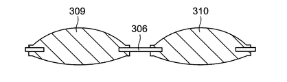
- the light emitting lens 309 and the light receiving lens 310 are formed on the lens frame 306 with a translucent resin in separate steps.
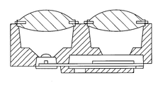
- the secondary mold 320 is formed of a light-shielding resin by insert molding the primary mold body formed in the step shown in FIG. 15B.
- a light shielding wall 330 is formed at the center of the light receiving / emitting portion to prevent light from directly entering the light receiving element from the light emitting element.
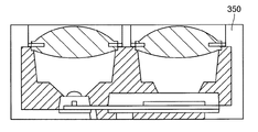
- the lens frame in which the lens is formed in FIG. 15C is arranged on the secondary mold 320 shown in FIG. 15D is the structure shown in FIG. 15E.
- a tertiary mold 350 is formed by insert molding to form an optical distance measuring device.
- FIG. 16A is a top view of FIG. 15B, showing the lead frame in the primary mold as a watermark.
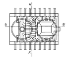
- 16B is a top view of FIG. 15D
- FIG. 16C is a transparent view thereof.
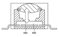
- 17A is a cross-sectional view taken along line AA ′ of FIG. 16C
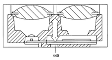
- FIG. 17B is a cross-sectional view taken along line BB ′ of FIG. 16C.
- a stress 440 acts as indicated by an arrow in the figure.
- the lens frame since the lens frame has a relatively large area of the flat plate portion, it is resistant to stress even if it expands.
- the light receiving header portion 450 is fixed in a direction orthogonal to the extending direction of the coupling portion between the light receiving header portion and the light emitting header portion, particularly with respect to the expansion of the light shielding wall at the intermediate portion between light receiving and light emitting. Since there is no, when it expands, it warps greatly.
- the relative positional relationship between the light emitting / receiving lens and the light emitting / receiving element changes from the relative positional relationship between the light emitting / receiving lens before the reflow and the light receiving / emitting element, As described in the triangulation principle, the spot position of the reflected light changes, and there is a problem that the distance measurement value shifts.
- an object of the present invention is to provide an optical distance measuring device that can perform distance measurement more accurately regardless of temperature and can be manufactured inexpensively and easily, and an electronic apparatus equipped with the same.
- the optical distance measuring device of the present invention is: A lead frame having a light emitting header portion, a light receiving header portion, and a coupling portion extending in one direction for coupling the light emitting header portion and the light receiving header portion on the same plane; A light emitting element mounted on the light emitting header, A light receiving element that is mounted on the light receiving header portion and detects a spot position of light emitted from the light emitting element and reflected by the measurement object; A translucent resin body for sealing the light emitting element and the light receiving element; A first light-shielding resin body having a light-shielding wall positioned between the light-emitting element and the light-receiving element; A light-emitting lens that is provided on the first light-shielding resin body so as to be positioned on the light-emitting element with a space therebetween; The first light-shielding resin body is provided so as to be positioned on the light-receiving element at an interval, and includes a
- the optical distance measuring device of the present invention is A light emitting device mounted on a lead frame; A light receiving element that is mounted on the same surface of the lead frame and detects a spot position of light emitted from the light emitting element and reflected by the measurement object; and A light-transmitting resin body that seals the light-emitting element and the light-receiving element; a first light-shielding resin body that integrally seals the light-transmitting resin body and has a light-shielding wall between the light-emitting element and the light-receiving element; A translucent light-emitting lens and a light-receiving lens disposed on the first light-shielding resin body,
- the light emitting header portion on which the light emitting element is mounted and the light receiving header portion on which the light receiving element is mounted are combined,
- the light receiving header portion and the light emitting header portion have a portion extending in a direction orthogonal to the extending direction of the coupling portion, and
- the lead frame can be used even in a high temperature environment during reflow. There will be no warping. Therefore, the relative positional relationship between the light receiving and emitting lenses and the light receiving and emitting elements does not vary, so that a highly accurate optical distance measuring device can be provided.
- Each of the first terminals is formed in the vicinity of the light shielding wall.
- each first terminal is formed in the vicinity of the light shielding wall, it is possible to effectively suppress warpage of the central portion between the light receiving and emitting elements having the greatest stress due to expansion.
- Each of the first terminals has a portion overlapping the light shielding wall in a direction substantially orthogonal to the extending direction of the coupling portion.
- the first terminal is formed in the vicinity of the light shielding wall in the central portion between the light emitting and receiving elements having the largest stress due to expansion that causes warping of the lead frame. Warpage can be prevented.
- the lead frame is While coupled to the light-emitting header portion, it has at least two second terminals extending in a direction substantially orthogonal to the extending direction of the coupling portion, Each said 2nd terminal is being fixed by the said 1st light-shielding resin body.
- the second light-emitting header unit is provided with two second terminals extending in the same direction as the first terminal, and the second terminal is fixed by the first light-shielding resin body. Has been. Therefore, in addition to the light receiving header portion, the second terminal coupled to the light emitting header portion is fixed by the first light-shielding resin body, so that the lead frame can be more effectively prevented from warping.
- the lead frame is While coupled to the light receiving header, the light receiving header portion has a third terminal extending substantially in the extending direction of the coupling portion on the side opposite to the light emitting header portion side in the extending direction of the coupling portion, The third terminal is fixed by the first light-shielding resin body.
- the light receiving header portion includes the third terminal coupled to the light receiving header portion on the side opposite to the light emitting header portion side in the extending direction of the coupling portion, and the third terminal is the first terminal.
- the light-shielding resin body is fixed. Therefore, since the third terminal is provided in the light receiving header portion in a direction orthogonal to the first terminal, and the third terminal is fixed by the first light-shielding resin body, the lead frame is reinforced more firmly. This can more effectively prevent the lead frame from warping.
- the lead frame is While coupled to the light emitting header, the light emitting header portion has a fourth terminal extending substantially in the extending direction of the coupling portion on the side opposite to the light receiving header portion side in the extending direction of the coupling portion, The fourth terminal is fixed by the first light-shielding resin body.
- the fourth terminal coupled to the light emitting header portion is provided on the side opposite to the light receiving header portion side in the direction in which the coupling portion extends in the light emitting header portion, and the fourth terminal is the first light shielding. It is fixed with a conductive resin body. Therefore, since the fourth terminal is provided in the light emitting header portion in a direction substantially orthogonal to the first terminal, and the fourth terminal is fixed by the first light-shielding resin body, the lead frame is further strengthened. The lead frame can be more effectively prevented from warping.
- the electronic device of the present invention is characterized by including the optical distance measuring device of the present invention.
- the highly heat-resistant optical distance measuring device of the present invention When the highly heat-resistant optical distance measuring device of the present invention is mounted on a personal computer or sanitary equipment, the distance to a person can be detected more accurately regardless of the temperature, and the equipment can be controlled. When installed, obstacles and steps can be detected more accurately regardless of temperature, and when used as a non-contact switch or non-contact controller, electronic devices can be controlled more accurately regardless of temperature.
- an optical distance measuring device that can perform distance measurement more accurately regardless of temperature, and that can be manufactured inexpensively and easily, and an electronic device equipped with the optical distance measuring device.
- FIG. 4B is a top view after secondary molding, which is the next step of the step shown in FIG. 4A.
- FIG. 4B is a transmission diagram of the structure shown in FIG. 4B. It is BB 'sectional drawing of FIG. 4C.
- FIG. 6B is a top view after secondary molding, which is the next step of the step shown in FIG. 6A.
- FIG. 6B is a transmission diagram of the structure shown in FIG. 6B. It is BB 'sectional drawing of FIG. 6C.
- FIG. 15B is a top view of FIG. 15B.
- FIG. 15D is a top view of FIG. 15D.
- FIG. 16B is a perspective view of the structure shown in FIG. 16B. It is AA 'sectional drawing of FIG. 16C. It is BB 'sectional drawing of FIG. 16C.
- FIG. 1A to 1C are plan views of the optical distance measuring device according to the first embodiment of the present invention.
- the cross-sectional structure diagram of each process of the present example is consistent with the cross-sectional structure diagrams shown in FIGS. 15A to 15F.
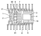
- FIG. 1A is a transmission diagram of the primary mold after the primary molding.
- a light-emitting header section 2 on which a light-emitting element 1 is mounted and a light-receiving header section 4 on which a light-receiving element 3 is mounted are combined, and temperature and humidity are combined. The expansion of the space between the light receiving and emitting elements 1 and 3 with respect to the expansion of the package due to is prevented.
- First reinforcing terminals 7 and 8 serving as first terminals are arranged on one and the other sides in a direction substantially orthogonal to the extending direction of the coupling portion 6 of the light receiving and emitting headers 2 and 4, respectively. , 8 are coupled to the light receiving header section 4.
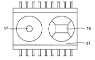
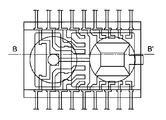
- FIG. 1B shows a top view after secondary molding, which is the next configuration of the process shown in FIG. 1A
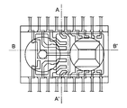
- FIG. 1C shows a transparent view thereof.
- 2A is a cross-sectional view taken along line AA ′ of FIG. 1C
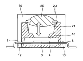
- FIG. 2B is a cross-sectional view taken along line BB ′ of FIG. 1C.
- the first reinforcing terminals 7 and 8 are coupled to the light receiving header portion 4 and taken out of the package. Moreover, each of the 1st reinforcement terminals 7 and 8 has the fixing
- the primary mold (translucent resin body) 18 on the light receiving side is covered with the (first light-shielding resin body) 21, except for the region where the reflected light beam is incident, 1 light-shielding resin body) 21.
- a lens frame 23 formed of a metal such as 42 alloy is disposed on the secondary mold 21, and a light emitting lens 29 (see FIG. 2B) formed of a translucent resin is provided on the lens frame 23.
- the lens frame 23 with the lenses 25 and 29 and the secondary mold body 21 are shielded from light so that the lens frame 23 with the lenses 25 and 29 and the secondary mold body 21 are fixed. It is covered with a tertiary mold (second light-shielding resin body) 30 made of a conductive resin.
- the light shielding wall 35 between the light receiving and emitting portions is greatly expanded, and stress is applied in the direction of the arrow in the figure.
- the lead frame 9 (see FIG. 1A) is warped. There is no such thing. Therefore, the relative positional relationship between the light emitting / receiving elements 1 and 3 and the light receiving and emitting lenses 25 and 29 does not shift even after the reflow, and the distance measurement value does not shift after the reflow.
- the first reinforcing terminals 7 and 8 have portions 90 and 91 that overlap the light shielding wall 35 in a direction substantially perpendicular to the direction in which the coupling portion 6 extends.
- the first reinforcing terminals 7 and 8 are arranged in the vicinity of the light shielding wall 35 at the center between the light emitting and receiving elements 1 and 3 where the stress due to expansion causing the warping of the lead frame 9 is the largest.
- the lead frame is prevented from warping.
- each of the first reinforcing terminals 7 and 8 has a portion that overlaps the light shielding wall 35 in a direction substantially orthogonal to the direction in which the coupling portion 6 extends. The lead frame can be effectively prevented from warping as long as it is formed in the vicinity of the light shielding wall.
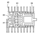
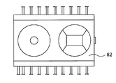
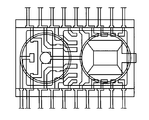
- FIG. 3A to 3C are plan views of the optical distance measuring device according to the second embodiment of the present invention. Specifically, FIG. 3A is a transparent view after the primary molding, and FIG. 3B is a perspective view of FIG. FIG. 3C is a top view after secondary molding, which is the next step of the step shown, and FIG. 3C is a transparent view of the structure shown in FIG. 3B.
- FIG. 3A is a transparent view after the primary molding
- FIG. 3B is a perspective view of FIG.
- FIG. 3C is a top view after secondary molding, which is the next step of the step shown
- FIG. 3C is a transparent view of the structure shown in FIG. 3B.
- the lead frame 80 has a plurality of second reinforcing terminals 40 as second terminals.
- the plurality of second reinforcing terminals 40 extend in a direction substantially orthogonal to the direction in which the coupling portion 81 of the light emitting / receiving headers 39 and 41 extends.
- Each said 2nd reinforcement terminal 40 is couple
- the light emitting header portion 41 is also fixed by the second reinforcing terminal 40 with a secondary mold 82 (see FIG. 3B) as a first light shielding resin body. Yes. According to the second embodiment, warpage due to expansion of the package due to reflow can be further prevented.
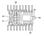
- FIG. 4A to 4C are plan views of the optical distance measuring device according to the third embodiment of the present invention. Specifically, FIG. 4A is a transparent view after the primary molding, and FIG. 4B is a plan view of FIG. 4A. 4C is a top view after the secondary molding, which is the next step of the step shown, and FIG. 4C is a transparent view of the structure shown in FIG. 4B.
- FIG. 4A is a transparent view after the primary molding
- FIG. 4B is a plan view of FIG. 4A.
- 4C is a top view after the secondary molding, which is the next step of the step shown
- FIG. 4C is a transparent view of the structure shown in FIG. 4B.
- the third embodiment only parts different from the first embodiment will be described.
- the lead frame 54 has a third reinforcing terminal 50 as a third terminal.
- the third reinforcing terminal 50 extends substantially in the direction in which the coupling portion 56 between the light receiving header portion 49 and the light emitting header portion 51 extends, and emits light in the direction in which the coupling portion 56 of the light receiving header portion 49 extends.
- An extending portion 68 is provided on the side opposite to the header portion 51 side. The third reinforcing terminal 50 is coupled to the light receiving header portion 49.
- FIG. 5 is a BB ′ cross-sectional view of FIG. 4C.
- the 3rd reinforcement terminal 50 has the fixing
- the fixing portion 55 of the third reinforcing terminal 50 coupled to the light receiving header portion 49 is fixed to the secondary mold 58, when the stress due to package expansion acts during reflow, the lead frame The fixing points can be increased also at the end portion of 54, and the warping of the lead frame can be prevented more firmly.
- FIG. 6A to 6C are plan views of the optical distance measuring device according to the fourth embodiment of the present invention. Specifically, FIG. 6A is a transparent view after the primary molding, and FIG. 6B is a perspective view of FIG. FIG. 6C is a top view after the secondary molding, which is the next step of the step shown, and FIG. 6C is a transparent view of the structure shown in FIG. 6B.
- FIG. 6A is a transparent view after the primary molding
- FIG. 6B is a perspective view of FIG.
- FIG. 6C is a top view after the secondary molding, which is the next step of the step shown
- FIG. 6C is a transparent view of the structure shown in FIG. 6B.
- FIG. 6C is a transparent view of the structure shown in FIG. 6B.
- the lead frame 69 has a fourth reinforcing terminal 60 as a fourth terminal.
- the fourth reinforcing terminal 60 extends substantially in the direction in which the coupling portion 83 between the light receiving header portion 59 and the light emitting header portion 61 extends, and receives light in the direction in which the coupling portion 83 of the light emitting header portion 61 extends.
- An extending portion 98 is provided on the side opposite to the header portion 59 side. Further, the fourth reinforcing terminal 60 is coupled to the light emitting header portion 61.
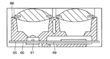
- FIG. 7 is a BB ′ cross-sectional view of FIG. 6C.
- the 4th reinforcement terminal 60 has the fixing
- the fixing portion 65 of the fourth reinforcing terminal 60 coupled to the light emitting header portion 61 is fixed by the secondary mold 66, when the stress due to the package expansion acts during reflow, the lead frame Since the fixing points increase at the end portion 69, the lead frame 69 can be more securely prevented from warping.
- the optical distance measuring device of the present invention when the optical distance measuring device of the present invention is mounted on an electronic device, the performance such as heat resistance of the optical distance measuring device can be improved. At the same time, a large number of elements can be mounted easily and in a short time by reflow. Therefore, for example, if it is installed in a personal computer, it is possible to accurately detect whether or not there is a person in front of the personal computer. In addition, when installed in a self-propelled cleaner, obstacles and steps can be accurately detected. In addition, it is possible to configure a non-contact switch that is mounted on a kitchen appliance and turns on / off the operation without contact. Further, it is possible to accurately perform processing such as volume control by detecting the distance to the hand, and it can be suitably executed for the operation of the electronic device when the hand is wet or dirty.
Landscapes
- Physics & Mathematics (AREA)
- Engineering & Computer Science (AREA)
- Electromagnetism (AREA)
- General Physics & Mathematics (AREA)
- Radar, Positioning & Navigation (AREA)
- Remote Sensing (AREA)
- Computer Networks & Wireless Communication (AREA)
- Measurement Of Optical Distance (AREA)
- Optical Radar Systems And Details Thereof (AREA)
- Length Measuring Devices By Optical Means (AREA)
Abstract
Description
(式1)

発光ヘッダ部と、受光ヘッダ部と、上記発光ヘッダ部と上記受光ヘッダ部とを結合する一方向に延びる結合部とを同一面上に有するリードフレームと、
上記発光ヘッダ部上に実装された発光素子と、
上記受光ヘッダ部上に実装されると共に、上記発光素子から出射されて測定対象物で反射された光のスポット位置を検出するための受光素子と、
上記発光素子および上記受光素子を封止する透光性樹脂体と、
上記透光性樹脂体を一体に封止すると共に、上記発光素子と、上記受光素子との間に位置する遮光壁を有する第1の遮光性樹脂体と、
上記第1の遮光性樹脂体に、上記発光素子の上に間隔をおいて位置するように設けられると共に、透光性を有する発光レンズと、
上記第1の遮光性樹脂体に、上記受光素子の上に間隔をおいて位置するように設けられると共に、透光性を有する受光レンズと
を備え、
上記リードフレームは、
上記受光ヘッダ部に結合する一方、上記結合部の延びる方向に略直交する方向に延在する少なくとも二本の第1の端子を有し、
上記各第1の端子は、上記第1の遮光性樹脂体により固定されていることを特徴としている。
リードフレーム上に実装された発光素子と、
リードフレームの同一面上に実装されるとともに発光素子から出射されて測定対象物で反射した光のスポット位置を検出する受光素子と、
発光素子および受光素子を封止する透光性樹脂体と、透光性樹脂体を一体に封止すると共に、発光素子と受光素子間に遮光壁を有する第1の遮光性樹脂体と、
第1の遮光性樹脂体上に配置される透光性を有する発光レンズおよび受光レンズと
を備え、
リードフレームにおいては、発光素子が搭載される発光ヘッダ部と、受光素子が搭載される受光ヘッダ部とが結合しており、
受光ヘッダ部と、発光ヘッダ部との結合部の延在する方向と直交方向に延在する部分を有すると共に、受光ヘッダ部に結合する少なくとも2本の第1の端子を備え、
上記第1の端子は、第1の遮光性樹脂体により固定されている。
上記各第1の端子は、上記遮光壁の近傍に形成されている。
上記各第1の端子は、上記遮光壁に上記結合部の延びる方向に略直交する方向に重なっている部分を有する。
上記リードフレームは、
上記発光ヘッダ部に結合する一方、上記結合部の延びる方向に略直交する方向に延在する少なくとも二本の第2の端子を有し、
上記各第2の端子は、上記第1の遮光性樹脂体により固定されている。
上記リードフレームは、
上記受光ヘッダに結合する一方、上記受光ヘッダ部における上記結合部の延びる方向の上記発光ヘッダ部側とは反対側に上記結合部の延びる方向に略延在する第3の端子を有し、
上記第3の端子は、上記第1の遮光性樹脂体により固定されている。
上記リードフレームは、
上記発光ヘッダに結合する一方、上記発光ヘッダ部における上記結合部の延びる方向の上記受光ヘッダ部側とは反対側に上記結合部の延びる方向に略延在する第4の端子を有し、
上記第4の端子は、上記第1の遮光性樹脂体により固定されている。
2,41,51,61 発光ヘッダ部
3 受光素子
4,39,49,59 受光ヘッダ部
6,56,81,83 結合部
7,8 第1補強端子
9,54,69,80 リードフレーム
21,58,66,82 2次モールド
35 遮光壁
40 第2補強端子
50 第3補強端子
55 第3補強端子の固定部
60 第4補強端子
65 第4補強端子の固定部
Claims (7)
- 発光ヘッダ部(2,41,51,61)と、受光ヘッダ部(4,39,49,59)と、上記発光ヘッダ部(2,41,51,61)と上記受光ヘッダ部(4,39,49,59)とを結合する一方向に延びる結合部(6,56,81,83)とを同一面上に有するリードフレーム(9,54,69,80)と、
上記発光ヘッダ部(2,41,51,61)上に実装された発光素子(1)と、
上記受光ヘッダ部上に実装されると共に、上記発光素子(1)から出射されて測定対象物で反射された光のスポット位置を検出するための受光素子(3)と、
上記発光素子(1)および上記受光素子(3)を封止する透光性樹脂体(17,18)と、
上記透光性樹脂体(17,18)を一体に封止すると共に、上記発光素子(1)と、上記受光素子(3)との間に位置する遮光壁(35)を有する第1の遮光性樹脂体(21,58,66,82)と、
上記第1の遮光性樹脂体(21)に、上記発光素子(1)の上に間隔をおいて位置するように設けられると共に、透光性を有する発光レンズ(29)と、
上記第1の遮光性樹脂体(21)に、上記受光素子(3)の上に間隔をおいて位置するように設けられると共に、透光性を有する受光レンズ(25)と
を備え、
上記リードフレーム(9,69)は、
上記受光ヘッダ部(4,39,49,59)に結合する一方、上記結合部(6,56)の延びる方向に略直交する方向に延在する少なくとも二本の第1の端子(7,8)を有し、
上記各第1の端子(7,8)は、上記第1の遮光性樹脂体(21)により固定されていることを特徴とする光学式測距装置。 - 請求項1に記載の光学式測距装置において、
上記各第1の端子(7,8)は、上記遮光壁(35)の近傍に形成されていることを特徴とする光学式測距装置。 - 請求項2に記載の光学式測距装置において、
上記各第1の端子(7,8)は、上記遮光壁(35)に上記結合部(6,56)の延びる方向に略直交する方向に重なっている部分(90,91)を有することを特徴とする光学式測距装置。 - 請求項1から3までのいずれか一項に記載の光学式測距装置において、
上記リードフレーム(80)は、
上記発光ヘッダ部(41)に結合する一方、上記結合部(81)の延びる方向に略直交する方向に延在する少なくとも二本の第2の端子(40)を有し、
上記各第2の端子(40)は、上記第1の遮光性樹脂体(82)により固定されていることを特徴とする光学式測距装置。 - 請求項1から4までのいずれか一項に記載の光学式測距装置において、
上記リードフレーム(54)は、
上記受光ヘッダに結合する一方、上記受光ヘッダ部(49)における上記結合部(56)の延びる方向の上記発光ヘッダ部(51)側とは反対側に上記結合部(56)の延びる方向に略延在する第3の端子(50)を有し、
上記第3の端子(50)は、上記第1の遮光性樹脂体(58)により固定されていることを特徴とする光学式測距装置。 - 請求項1から5までのいずれか一項に記載の光学式測距装置において、
上記リードフレーム(69)は、
上記発光ヘッダに結合する一方、上記発光ヘッダ部(61)における上記結合部(83)の延びる方向の上記受光ヘッダ部(59)側とは反対側に上記結合部(83)の延びる方向に略延在する第4の端子(60)を有し、
上記第4の端子(60)は、上記第1の遮光性樹脂体(66)により固定されていることを特徴とする光学式測距装置。 - 請求項1から6までのいずれか一項に記載の光学式測距装置を備えることを特徴とする電子機器。
Priority Applications (3)
| Application Number | Priority Date | Filing Date | Title |
|---|---|---|---|
| JP2014526832A JP5809753B2 (ja) | 2012-07-24 | 2013-07-01 | 光学式測距装置および電子機器 |
| US14/416,333 US9568596B2 (en) | 2012-07-24 | 2013-07-01 | Optical distance measuring apparatus and electronic apparatus |
| CN201380039255.2A CN104508424B (zh) | 2012-07-24 | 2013-07-01 | 光学式测距装置和电子设备 |
Applications Claiming Priority (2)
| Application Number | Priority Date | Filing Date | Title |
|---|---|---|---|
| JP2012-163867 | 2012-07-24 | ||
| JP2012163867 | 2012-07-24 |
Publications (1)
| Publication Number | Publication Date |
|---|---|
| WO2014017256A1 true WO2014017256A1 (ja) | 2014-01-30 |
Family
ID=49997072
Family Applications (1)
| Application Number | Title | Priority Date | Filing Date |
|---|---|---|---|
| PCT/JP2013/068009 Ceased WO2014017256A1 (ja) | 2012-07-24 | 2013-07-01 | 光学式測距装置および電子機器 |
Country Status (4)
| Country | Link |
|---|---|
| US (1) | US9568596B2 (ja) |
| JP (1) | JP5809753B2 (ja) |
| CN (1) | CN104508424B (ja) |
| WO (1) | WO2014017256A1 (ja) |
Cited By (13)
| Publication number | Priority date | Publication date | Assignee | Title |
|---|---|---|---|---|
| JP2016055428A (ja) * | 2014-09-11 | 2016-04-21 | ウェザッグ ゲーエムベーハー ウェルクゼウグファブリック | ハンドプライヤ |
| WO2016201465A3 (de) * | 2015-06-18 | 2017-02-09 | RobArt GmbH | Optischer triangulationssensor zur entfernungsmessung |
| US10860029B2 (en) | 2016-02-15 | 2020-12-08 | RobArt GmbH | Method for controlling an autonomous mobile robot |
| US11175670B2 (en) | 2015-11-17 | 2021-11-16 | RobArt GmbH | Robot-assisted processing of a surface using a robot |
| US11188086B2 (en) | 2015-09-04 | 2021-11-30 | RobArtGmbH | Identification and localization of a base station of an autonomous mobile robot |
| WO2021261496A1 (ja) * | 2020-06-22 | 2021-12-30 | シチズン電子株式会社 | Vcselモジュール |
| JP2022143348A (ja) * | 2021-03-17 | 2022-10-03 | 株式会社小糸製作所 | 受光素子及び測定装置 |
| JP2022143347A (ja) * | 2021-03-17 | 2022-10-03 | 株式会社小糸製作所 | 受光素子及び測定装置 |
| US11709489B2 (en) | 2017-03-02 | 2023-07-25 | RobArt GmbH | Method for controlling an autonomous, mobile robot |
| US11768494B2 (en) | 2015-11-11 | 2023-09-26 | RobArt GmbH | Subdivision of maps for robot navigation |
| US11789447B2 (en) | 2015-12-11 | 2023-10-17 | RobArt GmbH | Remote control of an autonomous mobile robot |
| US12140965B2 (en) | 2016-08-05 | 2024-11-12 | Rotrade Asset Management Gmbh | Method for controlling an autonomous mobile robot |
| US12169405B2 (en) | 2017-04-28 | 2024-12-17 | Rotrade Asset Management Gmbh | Method for navigation of a robot |
Families Citing this family (3)
| Publication number | Priority date | Publication date | Assignee | Title |
|---|---|---|---|---|
| CN105789196B (zh) | 2014-12-22 | 2019-10-08 | 日月光半导体制造股份有限公司 | 光学模块及其制造方法 |
| CN107192334A (zh) * | 2016-03-15 | 2017-09-22 | 信泰光学(深圳)有限公司 | 可调整光通量的测距装置 |
| JP6866174B2 (ja) * | 2017-02-02 | 2021-04-28 | 新光電子株式会社 | 反射型センサ |
Citations (6)
| Publication number | Priority date | Publication date | Assignee | Title |
|---|---|---|---|---|
| JPH05164925A (ja) * | 1991-12-16 | 1993-06-29 | Sharp Corp | 光集積回路、光ピックアップおよび光情報処理装置 |
| JP2002016196A (ja) * | 2000-04-24 | 2002-01-18 | Fuji Electric Co Ltd | リードフレーム、およびそれを用いた樹脂封止形半導体装置 |
| JP2009290009A (ja) * | 2008-05-29 | 2009-12-10 | Pearl Lighting Co Ltd | 反射型送受光装置 |
| JP2010114141A (ja) * | 2008-11-04 | 2010-05-20 | Sharp Corp | 受光・発光一体型光半導体装置および電子機器 |
| JP2011043433A (ja) * | 2009-08-21 | 2011-03-03 | Sharp Corp | 光学式測距センサ、および、それを搭載した電子機器 |
| JP2012037276A (ja) * | 2010-08-04 | 2012-02-23 | Sharp Corp | 光学式測距装置 |
Family Cites Families (9)
| Publication number | Priority date | Publication date | Assignee | Title |
|---|---|---|---|---|
| JPH07280552A (ja) * | 1994-04-12 | 1995-10-27 | Seikosha Co Ltd | 測距装置 |
| JPH11281351A (ja) | 1998-01-28 | 1999-10-15 | Fuji Electric Co Ltd | 測距装置 |
| JP2001099643A (ja) | 1999-07-23 | 2001-04-13 | Fuji Electric Co Ltd | 測距装置 |
| TW513558B (en) * | 2000-10-27 | 2002-12-11 | Fuji Electric Co Ltd | Range finder for automatic focusing |
| JP4016275B2 (ja) * | 2003-06-25 | 2007-12-05 | 富士電機デバイステクノロジー株式会社 | 測距装置 |
| JP4588544B2 (ja) | 2005-06-06 | 2010-12-01 | シャープ株式会社 | 光学式測距センサ |
| US20070210267A1 (en) * | 2006-02-27 | 2007-09-13 | Sharp Kabushiki Kaisha | Optical ranging sensor and warm water wash toilet seat |
| JP5178393B2 (ja) * | 2008-08-20 | 2013-04-10 | シャープ株式会社 | 光学式測距センサおよび電子機器 |
| US9525093B2 (en) * | 2009-06-30 | 2016-12-20 | Avago Technologies General Ip (Singapore) Pte. Ltd. | Infrared attenuating or blocking layer in optical proximity sensor |
-
2013
- 2013-07-01 JP JP2014526832A patent/JP5809753B2/ja not_active Expired - Fee Related
- 2013-07-01 CN CN201380039255.2A patent/CN104508424B/zh not_active Expired - Fee Related
- 2013-07-01 WO PCT/JP2013/068009 patent/WO2014017256A1/ja not_active Ceased
- 2013-07-01 US US14/416,333 patent/US9568596B2/en active Active
Patent Citations (6)
| Publication number | Priority date | Publication date | Assignee | Title |
|---|---|---|---|---|
| JPH05164925A (ja) * | 1991-12-16 | 1993-06-29 | Sharp Corp | 光集積回路、光ピックアップおよび光情報処理装置 |
| JP2002016196A (ja) * | 2000-04-24 | 2002-01-18 | Fuji Electric Co Ltd | リードフレーム、およびそれを用いた樹脂封止形半導体装置 |
| JP2009290009A (ja) * | 2008-05-29 | 2009-12-10 | Pearl Lighting Co Ltd | 反射型送受光装置 |
| JP2010114141A (ja) * | 2008-11-04 | 2010-05-20 | Sharp Corp | 受光・発光一体型光半導体装置および電子機器 |
| JP2011043433A (ja) * | 2009-08-21 | 2011-03-03 | Sharp Corp | 光学式測距センサ、および、それを搭載した電子機器 |
| JP2012037276A (ja) * | 2010-08-04 | 2012-02-23 | Sharp Corp | 光学式測距装置 |
Cited By (22)
| Publication number | Priority date | Publication date | Assignee | Title |
|---|---|---|---|---|
| JP2016055428A (ja) * | 2014-09-11 | 2016-04-21 | ウェザッグ ゲーエムベーハー ウェルクゼウグファブリック | ハンドプライヤ |
| WO2016201465A3 (de) * | 2015-06-18 | 2017-02-09 | RobArt GmbH | Optischer triangulationssensor zur entfernungsmessung |
| US11550054B2 (en) | 2015-06-18 | 2023-01-10 | RobArtGmbH | Optical triangulation sensor for distance measurement |
| US11188086B2 (en) | 2015-09-04 | 2021-11-30 | RobArtGmbH | Identification and localization of a base station of an autonomous mobile robot |
| US11768494B2 (en) | 2015-11-11 | 2023-09-26 | RobArt GmbH | Subdivision of maps for robot navigation |
| US12093050B2 (en) | 2015-11-17 | 2024-09-17 | Rotrade Asset Management Gmbh | Robot-assisted processing of a surface using a robot |
| US11175670B2 (en) | 2015-11-17 | 2021-11-16 | RobArt GmbH | Robot-assisted processing of a surface using a robot |
| US11789447B2 (en) | 2015-12-11 | 2023-10-17 | RobArt GmbH | Remote control of an autonomous mobile robot |
| US11709497B2 (en) | 2016-02-15 | 2023-07-25 | RobArt GmbH | Method for controlling an autonomous mobile robot |
| US10860029B2 (en) | 2016-02-15 | 2020-12-08 | RobArt GmbH | Method for controlling an autonomous mobile robot |
| US12140965B2 (en) | 2016-08-05 | 2024-11-12 | Rotrade Asset Management Gmbh | Method for controlling an autonomous mobile robot |
| US11709489B2 (en) | 2017-03-02 | 2023-07-25 | RobArt GmbH | Method for controlling an autonomous, mobile robot |
| US12169405B2 (en) | 2017-04-28 | 2024-12-17 | Rotrade Asset Management Gmbh | Method for navigation of a robot |
| WO2021261496A1 (ja) * | 2020-06-22 | 2021-12-30 | シチズン電子株式会社 | Vcselモジュール |
| JP2022179619A (ja) * | 2020-06-22 | 2022-12-02 | シチズン電子株式会社 | Vcselモジュール |
| JP7155455B2 (ja) | 2020-06-22 | 2022-10-18 | シチズン電子株式会社 | Vcselモジュール |
| JPWO2021261496A1 (ja) * | 2020-06-22 | 2021-12-30 | ||
| JP7628993B2 (ja) | 2020-06-22 | 2025-02-12 | シチズン電子株式会社 | Vcselモジュール |
| JP2022143347A (ja) * | 2021-03-17 | 2022-10-03 | 株式会社小糸製作所 | 受光素子及び測定装置 |
| JP2022143348A (ja) * | 2021-03-17 | 2022-10-03 | 株式会社小糸製作所 | 受光素子及び測定装置 |
| JP7696214B2 (ja) | 2021-03-17 | 2025-06-20 | 株式会社小糸製作所 | 受光素子及び測定装置 |
| JP7696215B2 (ja) | 2021-03-17 | 2025-06-20 | 株式会社小糸製作所 | 受光素子及び測定装置 |
Also Published As
| Publication number | Publication date |
|---|---|
| JPWO2014017256A1 (ja) | 2016-07-07 |
| US20150260829A1 (en) | 2015-09-17 |
| US9568596B2 (en) | 2017-02-14 |
| CN104508424B (zh) | 2016-09-28 |
| CN104508424A (zh) | 2015-04-08 |
| JP5809753B2 (ja) | 2015-11-11 |
Similar Documents
| Publication | Publication Date | Title |
|---|---|---|
| JP5809753B2 (ja) | 光学式測距装置および電子機器 | |
| JP5399525B2 (ja) | 光学式測距装置および電子機器 | |
| JP4510930B2 (ja) | 撮像装置及び半導体回路素子 | |
| JP2008051764A (ja) | 測距センサ、及びその測距センサを搭載した電子機器 | |
| US8305363B2 (en) | Sensing system and locating method thereof | |
| JP5287906B2 (ja) | 赤外線温度センサ、電子機器、および赤外線温度センサの製造方法 | |
| JP5399526B2 (ja) | 光学式測距装置および電子機器 | |
| KR102372335B1 (ko) | 가요성 표시 장치 및 그 구동 방법 | |
| JP5425014B2 (ja) | 光学式測距装置 | |
| JP2013509699A5 (ja) | ||
| JP2009250785A (ja) | 撮像装置 | |
| JP5481290B2 (ja) | 焦電型赤外線センサ | |
| JP4466083B2 (ja) | 測距用光源及び測距装置 | |
| JP2014055819A (ja) | 赤外線センサモジュール | |
| JP2018040582A (ja) | 放射線検出器 | |
| JP2015081769A (ja) | 光学式物体位置検出装置 | |
| JP5333641B2 (ja) | 赤外線温度センサ、電子機器、および赤外線温度センサの製造方法 | |
| CN111508941B (zh) | 光学感测芯片封装结构 | |
| JP2021170018A (ja) | 受光装置およびこれを備えた光電式エンコーダ | |
| JP2017103347A (ja) | 基板同士の組立方法 | |
| JP5952096B2 (ja) | 光半導体装置 | |
| JP5278276B2 (ja) | 測距用光源及びそれを用いた測距装置 | |
| JP2006078376A (ja) | 光学式変位センサ | |
| JP3573400B2 (ja) | 光学式入力装置 | |
| JP2019016624A (ja) | フォトインタラプタ、及びこれを備える近接覚センサ |
Legal Events
| Date | Code | Title | Description |
|---|---|---|---|
| 121 | Ep: the epo has been informed by wipo that ep was designated in this application |
Ref document number: 13822267 Country of ref document: EP Kind code of ref document: A1 |
|
| ENP | Entry into the national phase |
Ref document number: 2014526832 Country of ref document: JP Kind code of ref document: A |
|
| WWE | Wipo information: entry into national phase |
Ref document number: 14416333 Country of ref document: US |
|
| NENP | Non-entry into the national phase |
Ref country code: DE |
|
| 122 | Ep: pct application non-entry in european phase |
Ref document number: 13822267 Country of ref document: EP Kind code of ref document: A1 |