WO2014017209A1 - ねじ緩み止め構造 - Google Patents
ねじ緩み止め構造 Download PDFInfo
- Publication number
- WO2014017209A1 WO2014017209A1 PCT/JP2013/066362 JP2013066362W WO2014017209A1 WO 2014017209 A1 WO2014017209 A1 WO 2014017209A1 JP 2013066362 W JP2013066362 W JP 2013066362W WO 2014017209 A1 WO2014017209 A1 WO 2014017209A1
- Authority
- WO
- WIPO (PCT)
- Prior art keywords
- hole
- pin
- screw
- jig
- bolt
- Prior art date
- Legal status (The legal status is an assumption and is not a legal conclusion. Google has not performed a legal analysis and makes no representation as to the accuracy of the status listed.)
- Ceased
Links
Images




Classifications
-
- F—MECHANICAL ENGINEERING; LIGHTING; HEATING; WEAPONS; BLASTING
- F16—ENGINEERING ELEMENTS AND UNITS; GENERAL MEASURES FOR PRODUCING AND MAINTAINING EFFECTIVE FUNCTIONING OF MACHINES OR INSTALLATIONS; THERMAL INSULATION IN GENERAL
- F16F—SPRINGS; SHOCK-ABSORBERS; MEANS FOR DAMPING VIBRATION
- F16F9/00—Springs, vibration-dampers, shock-absorbers, or similarly-constructed movement-dampers using a fluid or the equivalent as damping medium
- F16F9/32—Details
- F16F9/3207—Constructional features
- F16F9/3228—Constructional features of connections between pistons and piston rods
-
- F—MECHANICAL ENGINEERING; LIGHTING; HEATING; WEAPONS; BLASTING
- F16—ENGINEERING ELEMENTS AND UNITS; GENERAL MEASURES FOR PRODUCING AND MAINTAINING EFFECTIVE FUNCTIONING OF MACHINES OR INSTALLATIONS; THERMAL INSULATION IN GENERAL
- F16F—SPRINGS; SHOCK-ABSORBERS; MEANS FOR DAMPING VIBRATION
- F16F9/00—Springs, vibration-dampers, shock-absorbers, or similarly-constructed movement-dampers using a fluid or the equivalent as damping medium
- F16F9/32—Details
- F16F9/3207—Constructional features
- F16F9/3235—Constructional features of cylinders
- F16F9/3242—Constructional features of cylinders of cylinder ends, e.g. caps
-
- F—MECHANICAL ENGINEERING; LIGHTING; HEATING; WEAPONS; BLASTING
- F16—ENGINEERING ELEMENTS AND UNITS; GENERAL MEASURES FOR PRODUCING AND MAINTAINING EFFECTIVE FUNCTIONING OF MACHINES OR INSTALLATIONS; THERMAL INSULATION IN GENERAL
- F16B—DEVICES FOR FASTENING OR SECURING CONSTRUCTIONAL ELEMENTS OR MACHINE PARTS TOGETHER, e.g. NAILS, BOLTS, CIRCLIPS, CLAMPS, CLIPS OR WEDGES; JOINTS OR JOINTING
- F16B39/00—Locking of screws, bolts or nuts
- F16B39/22—Locking of screws, bolts or nuts in which the locking takes place during screwing down or tightening
- F16B39/28—Locking of screws, bolts or nuts in which the locking takes place during screwing down or tightening by special members on, or shape of, the nut or bolt
- F16B39/32—Locking by means of a pawl or pawl-like tongue
-
- F—MECHANICAL ENGINEERING; LIGHTING; HEATING; WEAPONS; BLASTING
- F16—ENGINEERING ELEMENTS AND UNITS; GENERAL MEASURES FOR PRODUCING AND MAINTAINING EFFECTIVE FUNCTIONING OF MACHINES OR INSTALLATIONS; THERMAL INSULATION IN GENERAL
- F16F—SPRINGS; SHOCK-ABSORBERS; MEANS FOR DAMPING VIBRATION
- F16F2230/00—Purpose; Design features
- F16F2230/0041—Locking; Fixing in position
Definitions
- the present invention relates to a screw loosening prevention structure that restricts relative rotation between two members coupled by screwing.
- a screw loosening prevention structure for example, there are a structure using a set screw for stopping rotation of a member, and a structure in which a caulking portion is formed by plastic deformation of a part of a screw member.
- JP 2008-121753A discloses a method in which a concave portion and a protruding portion that are engaged with each other are formed between a screw and a washer to restrict relative rotation of both.
- An object of the present invention is to provide a screw loosening prevention structure in which screw loosening prevention is reliably performed.
- a screw loosening prevention structure that restricts relative rotation between a first member and a second member that are coupled by screwing, and a first hole formed in the first member; A second hole formed in the second member; a pin inserted into the second hole; and a biasing member that is interposed in the second hole and biases the pin in a direction of pushing the pin out of the second hole.
- the pin is inserted across the first hole and the second hole when the first hole and the second hole coincide with the relative rotation of the first member and the second member.
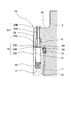
- FIG. 1 is a cross-sectional view of a hydraulic cylinder provided with a screw locking structure according to a first embodiment of the present invention.
- FIG. 2 is an enlarged cross-sectional view of a part of the hydraulic cylinder.
- FIG. 3 is a cross-sectional view showing how the cylinder head is loosened.
- 4 is a cross-sectional view taken along line AA in FIG.
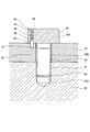
- FIG. 5 is a cross-sectional view of the screw locking structure according to the second embodiment of the present invention.
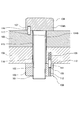
- FIG. 6 is a cross-sectional view of the screw locking structure according to the third embodiment of the present invention.
- FIG. 7 is a cross-sectional view of the screw locking structure according to the fourth embodiment of the present invention.
- FIG. 8 is a cross-sectional view of the screw locking structure according to the fifth embodiment of the present invention.
- the hydraulic cylinder 1 is provided with a screw loosening prevention structure according to an embodiment of the present invention described later.
- the hydraulic cylinder 1 includes a cylindrical cylinder tube 4, a piston 6 slidably accommodated inside the cylinder tube 4, a piston rod 7 connected to the piston 6, and a piston rod 7 slidably supported. And a cylinder head 5 to be provided.
- the inner side of the cylinder tube 4 is divided into a head side chamber 2 and a bottom side chamber 3 by a piston 6.
- the head side chamber 2 is provided on the head side where the piston rod 7 protrudes from the cylinder tube 4, and is defined by the cylinder tube 4, the piston 6, the piston rod 7, and the cylinder head 5.
- the bottom side chamber 3 is provided on the bottom side of the cylinder tube 4 and is partitioned by the cylinder tube 4 and the piston 6.
- hydraulic fluid (working fluid) supplied from the pump side of the hydraulic source flows into the bottom chamber 3 through the bottom passage (not shown), and the piston 6 moves to the head side (FIG. 1). And hydraulic oil in the head side chamber 2 flows out through the head side passage (not shown) to the tank side of the hydraulic power source.
- the piston rod 7 is connected to a load (not shown), and the cylinder tube 4 is connected to a fixed portion (not shown).
- a load connected to the piston rod 7 is driven.
- the cylinder tube 4 and the cylinder head 5 are formed in a cylindrical shape.
- An internal thread 12 is formed on the inner periphery of the cylinder tube 4.
- a male screw 11 is formed on the outer periphery of the cylinder head 5.
- Seal rings 13 and 14 are interposed between the cylinder tube 4 and the cylinder head 5.
- O-rings are employed as the seal rings 13 and 14, but are not limited to O-rings.
- a sealing member such as an X ring may be used as appropriate.
- the cylinder head 5 and the cylinder tube 4 are first and second members that are screwed together via screws 11 and 12. Between the cylinder tube 4 and the cylinder head 5, a screw loosening prevention structure 15 that restricts the relative rotation of both is provided.
- the screw locking structure 15 extends over the first hole 16 and the first through hole 21 formed in the cylinder head 5, the second hole 17 formed in the cylinder tube 4, and the first hole 16 and the second hole 17. And a spring 19 that is interposed in the second hole 17 and biases the pin 18 in a direction of pushing the pin 18 from the second hole 17 to the first hole 16.
- the single screw locking structure 15 is provided, but the number is not limited to one. In order to obtain a predetermined screw loosening prevention performance including this embodiment and other embodiments described later, a plurality of screw loosening prevention structures 15 may be provided.
- the columnar pin 18 includes a cylindrical outer peripheral surface 18A extending in the central axis direction, and inclined end portions 18B formed in a tapered shape (conical frustum shape) at both ends thereof. 18C and end faces 18D and 18E formed in a planar shape perpendicular to the central axis at both ends thereof.
- the spring 19 is a coiled metal spring and is interposed between the bottom 17C of the second hole 17 and the end face 18E of the pin 18 by being compressed.
- the spring 19 is a biasing member that biases the pin 18 in a direction of pushing out the pin 18 from the second hole 17.
- the urging member is not limited to the above-described configuration, and other shapes of metal springs or an elastic material such as rubber may be used.
- the first hole 16 has a cylindrical inner peripheral surface 16 ⁇ / b> A, an opening end 16 ⁇ / b> B that opens to the joining end surface 5 ⁇ / b> A of the cylinder head 5, and a bottom portion 16 ⁇ / b> C formed inside the cylinder head 5.
- the second hole 17 has a cylindrical inner peripheral surface 17 ⁇ / b> A, an opening end 17 ⁇ / b> B that opens to the joining end surface 4 ⁇ / b> A of the cylinder tube 4, and a bottom portion 17 ⁇ / b> C formed inside the cylinder tube 4.
- the first hole 16 and the second hole 17 are formed such that their center lines extend in parallel with the center line O of the hydraulic cylinder 1 and the distance from the center line O is equal to each other.
- the first hole 16 and the second hole 17 are aligned and extend coaxially, and the open ends of the first hole 16 and the second hole 17 Are matched to each other without any steps.
- the first through hole 21 extends coaxially with the first hole 16 and is formed to penetrate the cylinder head 5.
- the first through hole 21 has a female screw 22 formed on the inner periphery thereof, an opening end 21 ⁇ / b> A that opens to the bottom 16 ⁇ / b> C of the first hole 16, and an opening end 21 ⁇ / b> B that opens to the outer end surface 5 ⁇ / b> B of the cylinder head 5. .
- FIG. 3 is a cross-sectional view showing how the cylinder head 5 is assembled to the cylinder tube 4.
- a screw-like jig 25 inserted into the first through hole 21 is used.
- the jig 25 includes a screw portion 25A in which a male screw 26 is formed on the outer periphery, a head portion 25B formed in a proximal end portion of the screw portion 25A, and a screw portion 25A formed in a planar shape perpendicular to the central axis. And a tip 25C. As shown in FIG.
- the jig 25 is inserted into the first through hole 21 and assembled to the cylinder head 5, and the tip 25 ⁇ / b> C is positioned near the opening end 16 ⁇ / b> B of the first hole 16. It has a length for closing 16B.
- the screw portion 25A is provided in the jig 25.
- the present invention is not limited to this, and the screw portion 25A may not be provided.
- the jig 25 may be a rod-shaped member that can slide in the axial direction of the first through hole 21.
- the process of assembling the cylinder head 5 to the cylinder tube 4 is performed by the following processes.
- the jig 25 is assembled to the cylinder head 5 so that the male screw 26 of the screw portion 25A is screwed into the female screw 22 of the first through hole 21 and the head portion 25B contacts the outer end surface 5B of the cylinder head 5. Thereby, the screw portion 25A of the jig 25 is inserted into the first hole 16, and the tip 25C of the screw portion 25A is positioned in the vicinity of the opening end 16B of the first hole 16 to close the opening end 16B.
- the [loosening prevention step] is not limited to the above-described configuration, and may be as follows.
- the cylinder head 5 is screwed with a predetermined tightening torque, and the inclined end portion 18B of the pin 18 is brought into sliding contact with the opening end 16B of the first hole 16 to match the first hole 16 and the second hole 17 (FIG. 3). reference).
- the jig 25 is extracted from the first hole 16 in a state where the first hole 16 and the second hole 17 are matched.
- the pin 18 is pushed out of the second hole 17 by following the jig 25 by the biasing force of the spring 19, and is moved into the second hole 17 and the first hole 16. Inserted across (see FIG. 2).
- the screw loosening prevention structure 15 that restricts the relative rotation between the cylinder head 5 (first member) and the cylinder tube 4 (second member) coupled by screwing the screws 11 and 12 is the cylinder head 5.
- the pin 18 is inserted across the first hole 16 and the second hole 17 in a state where the cylinder head 5 and the cylinder tube 4 are aligned. It was supposed to be.
- a first through hole 21 that communicates with the first hole 16 is formed in the cylinder head 5, and the first through hole 21 is inserted from the outside into the first hole 16.
- Tool 25 was used.
- a jig is inserted from the outside into the first hole 16 through the first through hole 21.
- the jig 25 closes the opening end 16B of the first hole 16 with the tip 25C, and allows the pin 18 pushed out from the second hole 17 by the biasing force of the biasing member (spring 19) to enter the first hole 16. regulate.
- the jig 25 When releasing the fastening of the cylinder head 5 and the cylinder tube 4, the jig 25 is screwed into the first through hole 21 and inserted into the first hole 16, and the pin 18 is resisted against the biasing force of the spring 19. It extrudes from the 1st hole 16 (refer FIG. 3). In this way, when the pin 18 is extracted from the first hole 16, the cylinder head 5 and the cylinder tube 4 can be rotated relative to each other, and the fastening of both can be released. Therefore, the cylinder head 5 can be repeatedly attached to and detached from the cylinder tube 4.
- a nut 31 for fastening the piston 6 is provided at the tip of the piston rod 7.
- the piston 6 and the nut 31 are formed in a cylindrical shape.
- the piston 6 is fitted to the tip shaft portion 7 ⁇ / b> A of the piston rod 7.
- a male screw 32 is formed on the outer periphery of the distal end shaft portion 7A of the piston rod 7.
- a female thread 33 is formed on the inner periphery of the nut 31.
- Piston rod 7 and nut 31 are first and second members that are screwed together via screws 32 and 33. Between the piston rod 7 and the nut 31, a screw loosening prevention structure 35 that restricts the relative rotation of both is provided.
- the screw locking structure 35 includes a first hole 36 and a first through hole 41 formed in the nut 31, a second hole 37 formed in the piston rod 7, and a first hole 36. And a pin 38 inserted across the second hole 37, and a spring 39 that is interposed in the second hole 37 and biases the pin 38 in a direction of pushing the pin 38 from the second hole 37 to the first hole 36. .
- the pin 38 is inserted across the second hole 37 and the first hole 36 by the biasing force of the spring 39, the relative rotation of the piston rod 7 and the nut 31 is restricted.
- the first hole 36 and the second hole 37 are formed so that their center lines extend in a direction perpendicular to the center line O of the hydraulic cylinder 1, and match each other with the nut 31 fastened to the piston rod 7. Are arranged so as to extend on the same axis.
- the center lines of the first hole 36 and the second hole 37 are provided so as to intersect with the center line O of the hydraulic cylinder 1, but the present invention is not limited to this configuration.
- the center lines of the first hole 36 and the second hole 37 may be provided so as not to intersect with the center line O of the hydraulic cylinder 1.
- the first through hole 41 extends coaxially with the first hole 36 and is formed so as to penetrate the nut 31.
- the first through-hole 41 is formed with an internal thread 42 into which a jig (not shown) is screwed.
- the process of assembling the piston 6 to the piston rod 7 via the nut 31 is performed by the following processes.
- the first hole 36 opens to the inner periphery of the nut 31 (first member)
- the second hole 37 opens to the outer periphery of the piston rod 7 (second member)
- the first hole 36 matches the second hole 37 as the nut 31 is screwed into the piston rod 7.
- the pin 38 restricts the relative rotation between the nut 31 and the piston rod 7. The process of assembling the piston 6 to the piston rod 7 is completed.
- the screw locking structure 35 includes a first through hole 41 through which a jig inserted from the outside into the first hole 36 is inserted.
- the first through hole 41 communicates with the first hole 36 and is formed in the nut 31.
- a screw-like jig (not shown) is screwed into the first through hole 41 and inserted into the first hole 36, and the pin 38 is attached to the spring 39. Push out from the first hole 36 against the force.
- the nut 31 and the piston rod 7 can be rotated relative to each other, and the fastening of both can be released. Accordingly, the nut 31 can be repeatedly attached to and detached from the piston rod 7.
- the jig is inserted in the first through hole 41 and assembled to the nut 31, and the tip of the jig is located near the opening end of the first hole 36 and has a length for closing the opening end.
- the jig is provided with a screw portion. Not only this but the rod-shaped thing which can slide in the axial direction of the 1st through-hole 41 may be sufficient. Moreover, not only the structure mentioned above but the 1st through-hole 41 does not need to be provided when it is not necessary to cancel
- the screw is loosened in which the pin 18 is inserted across the first and second members (the cylinder head 5 and the cylinder tube 4) that are screwed together via the screws 11 and 12.
- the screw loosening prevention structure 35 in which the pin 38 is inserted across the first and second members (the nut 31 and the piston rod 7) that are screwed together with the fastening structure 15 and the screws 32 and 33 has been described.
- the first member (cylinder head 5, nut 31) and the second member (cylinder tube 4, piston rod 7) are fastened by screwing, the first holes 16, 36 and the second The pins 18 and 38 pushed out from the second holes 17 and 37 by the urging force of the springs 19 and 39 in a state where the holes 17 and 37 are aligned are inserted across the second holes 17 and 37 and the first holes 16 and 36.
- the relative rotation of the first member (cylinder head 5 and nut 31) and the second member (cylinder tube 4 and piston rod 7) is restricted by the pins 18 and 38.
- the second member (fastened member 54) is sandwiched between the first and third members (bolts 55 and the main body 53) that are screwed together via the screws 51 and 52.
- the pin 63 is interposed between the first and second members (the bolt 55 and the fastened member 54).
- a fastened member 54 is fastened to the main body 53 via a bolt 55.
- a bolt hole 56 through which the bolt 55 is inserted is formed in the fastened member 54.
- a male screw 51 is formed in the threaded portion 55B of the bolt 55, while a female screw 52 is formed in the screw hole 53A of the main body 53.
- a screw loosening prevention structure 60 that restricts the relative rotation of both is provided.
- the screw locking structure 60 includes a first hole 57 and a first through hole 58 formed in the head portion 55A of the bolt 55, a second hole 59 formed in the fastened member 54, a first hole 57, and a second hole.
- a pin 63 inserted over the hole 59; and a spring 64 interposed in the second hole 59 and biasing the pin 63 in a direction of pushing the pin 63 from the second hole 59 to the first hole 57.
- the first hole 57 and the second hole 59 are formed so as to extend in parallel with the central axis of the bolt 55, so that the fastened member 54 is fastened via the bolt 55 so as to coincide with each other and extend coaxially. Placed in.
- the first through hole 58 extends coaxially with the first hole 57 and is formed to penetrate the head portion 55A of the bolt 55.
- the first through hole 58 is formed with a female screw 61 on the inner periphery thereof, into which a screw-like jig (not shown) is screwed.
- the jig is inserted into the first through hole 58 and assembled to the bolt 55, and the tip thereof is positioned in the vicinity of the opening end of the first hole 57 and has a length for closing the opening end.
- tool was used in this Embodiment, it is not restricted to this, For example, you may use the rod-shaped thing which can slide to the axial direction of a 1st through-hole.
- the process of assembling the fastened member 54 to the main body 53 via the bolt 55 is performed by the following processes.
- the [loosening prevention step] is not limited to the above-described configuration, and the jig may be extracted from the first hole 57 in a state where the first hole 57 and the second hole 59 are matched.
- the third member (fastened member 54) is sandwiched between the first and second members (bolts 55 and the main body 53) that are screwed together via the screws 51 and 52. Then, the pin 73 is inserted across the first, second, and third members (the bolt 55, the main body 53, and the fastened member 54).
- the first member is the bolt 55
- the second member is the fastened member 54
- the third member is the main body 53.
- the first member is the bolt 55
- the second member is the main body 53
- the third member is the fastened member 54.
- a screw loosening prevention structure 70 that restricts relative rotation of each is provided.
- the screw locking structure 70 includes a first hole 57 and a first through hole 58 formed in the head portion 55 ⁇ / b> A of the bolt 55, a third hole 79 formed in the fastened member 54, and a first hole formed in the main body 53.
- a spring 64 to be energized.
- the first hole 57, the third hole 79, and the second hole 78 are formed so as to extend in parallel with the central axis of the bolt 55, and match each other in a state where the fastened member 54 is fastened via the bolt 55. It arrange
- the process of assembling the fastened member 54 to the main body 53 via the bolt 55 is performed by the following processes.
- the [loosening prevention step] is not limited to the above-described configuration, and the jig may be removed from the first hole 57 in a state where the first hole 57 is aligned with the third hole 79 and the second hole 78. Good.
- the screw locking structure 70 of the third embodiment includes the fastened member 54 (third member) interposed between the bolt 55 (first member) and the main body 53 (second member). Since the third hole 79 through which the pin 73 is inserted is formed in the fastened member 54 (third member), the relative rotation of the bolt 55 and the main body 53 that are screwed through the screws 51 and 52 is restricted, and the bolt The locking member 54 can be positioned and the fastening member 54 can be positioned.
- the screw locking structure 80 In the screw locking structure 80 according to the fourth embodiment, the third member (fastened member 54) is sandwiched between the second and first members (bolts 55 and the main body 53) that are screwed together via the screws 51 and 52. Then, the pin 84 is inserted across the second and third members (the bolt 55 and the fastened member 54).
- the first member is the bolt 55
- the second member is the fastening member 54
- the third member is the main body 53.
- the first member is the main body 53
- the second member is the bolt 55
- the third member is the fastened member 54.
- a screw loosening prevention structure 80 that restricts the relative rotation of both is provided.
- the second hole 82 and the first hole 81 are formed so as to extend parallel to the central axis of the bolt 55, so that the fastened member 54 is fastened via the bolt 55 so as to coincide with each other and extend coaxially. Placed in.
- the second through hole 83 extends coaxially with the second hole 82 and is formed so as to penetrate the head portion 55A of the bolt 55.
- a rod-shaped jig (not shown) is inserted into the second through hole 83.
- the pin 84 is formed with a screw hole 86 that opens at an end surface thereof.
- a screw (not shown) formed at the tip of the jig is screwed into the screw hole 86.
- the jig has a length such that the tip of the jig is engaged with the pin 84 while being inserted into the second through hole 83 and assembled to the bolt 55.
- the process of assembling the fastened member 54 to the main body 53 via the bolt 55 is performed by the following processes.
- the [loosening prevention step] is not limited to the above-described configuration, and the jig may be removed from the pin 84 and removed from the second hole 82 in a state where the second hole 82 and the first hole 81 are matched. .
- the third and fourth members are interposed between the first and second members (nuts 103 and bolts 104) that are screwed together via the screws 102 and 101. 106) is sandwiched.
- the pin 107 is inserted across the second and third members (bolt 104, fastened member 105), and the pin 108 is inserted across the first and fourth members (nut 103, fastened member 106). .
- Fastened members 105 and 106 are fastened through bolts 104 and nuts 103.
- Bolt holes 115 and 116 through which the bolts 104 are inserted are formed in the fastened members 105 and 106, respectively.
- a male thread 101 is formed on the threaded portion 104B of the bolt 104, while a female thread 102 is formed on the inner periphery of the nut 103.
- the screw loosening prevention structure 100 restricts relative rotation of the bolt 104 and the nut 103 via the pins 107 and 108.
- the first pin 107 is provided across the second hole 114 formed in the head 104A of the bolt 104 and the third hole 117 formed in the fastened member 105, and restricts relative rotation of both.
- the second pin 108 is provided across the nut 103 and the fastened member 106, and restricts relative rotation of both.
- the fastening member 106 is formed with a fourth hole 113 into which the base end portion of the second pin 108 and the spring 109 are inserted.
- the nut 103 is formed with a first hole 111 into which the tip of the second pin 108 is inserted, and a first through hole 112 extending coaxially with the first hole 111.
- a jig (not shown) is inserted into the first through hole 112, and the opening end of the first hole 111 is blocked by the tip of the jig.
- the jig is removed from the first hole 111.
- the nut 103 is screwed with a predetermined torque and the first hole 111 is made to coincide with the fourth hole 113 while being rotated once with respect to the bolt 104.
- the second pin pushed out from the fourth hole 113 by the biasing force of the spring 109 is inserted across the first hole 111 and the fourth hole 113.
- the rotation of the nut 103 is restricted by the second pin 108 held by the urging force of the spring 109, and the rotation of the bolt 104 is restricted by the first pin 107.
- first pin 107 that restricts the rotation of the bolt 104 is not limited to the above-described configuration, and may be configured to be held by the urging force of the spring, similarly to the second pin 108.
- the screw locking structure of the nut 103 may be the same as the screw locking structure 35 shown in FIG. Specifically, a second hole is formed in the outer periphery of the threaded portion 104B of the bolt 104, and a spring and a pin are accommodated in the second hole, while a second hole opened in the inner periphery (the female thread 102) of the nut 103. It is good also as a structure in which one hole is formed. In this case, as the nut 103 is screwed, the pin is inserted across the second hole and the first hole by the biasing force of the spring, and the relative rotation of the nut 103 is restricted.
Landscapes
- Engineering & Computer Science (AREA)
- General Engineering & Computer Science (AREA)
- Mechanical Engineering (AREA)
- Fluid-Damping Devices (AREA)
- Actuator (AREA)
- Transmission Devices (AREA)
Abstract
ねじ11、12の螺合によって結合されるシリンダヘッド5(第一部材)及びシリンダチューブ4(第二部材)どうしの相対回転を規制するねじ緩み止め構造15は、シリンダヘッド5に形成される第一穴16と、シリンダチューブ4に形成される第二穴17と、第二穴17に挿入されるピン18と、第二穴17に介装されてピン18を第二穴17から押し出す方向に付勢する付勢部材(スプリング19)と、を備え、ピン18は、シリンダヘッド5とシリンダチューブ4が合致した状態において第一穴16と第二穴17に渡って挿入されるものとした。
Description
本発明は、ねじの螺合によって結合される二つの部材どうしの相対回転を規制するねじ緩み止め構造に関するものである。
従来、ねじ緩み止め構造として、例えば部材の回転止めを行うセットスクリュを用いるものや、ネジ部材の一部を塑性変形させてカシメ部を形成するものがあった。
JP2008-121753Aには、ビスとワッシャの間に互いに係合する凹部及び突起部を形成して両者の相対回転を規制するものが開示されている。
しかしながら、JP2008-121753Aに開示のねじ緩み止め構造にあっては、ねじの螺合を解除する方向に大きなトルクが加わる場合や、振動や衝撃を受ける場合に、ねじの緩みが生じるという問題点があった。
本発明は、ねじの緩み止めが確実に行われるねじ緩み止め構造を提供することを目的とする。
本発明のある態様によれば、ねじの螺合によって結合される第一部材及び第二部材どうしの相対回転を規制するねじ緩み止め構造であって、第一部材に形成される第一穴と、第二部材に形成される第二穴と、第二穴に挿入されるピンと、第二穴に介装されてピンを第二穴から押し出す方向に付勢する付勢部材と、を備え、ピンは、第一部材と第二部材の相対回転に伴って前記第一穴と前記第二穴が合致した際に、第一穴と第二穴に渡って挿入される。
以下、添付図面を参照しながら本発明の実施形態について説明する。
(第1実施形態)
まず、図1に示す油圧シリンダ(流体圧シリンダ)1について説明する。この油圧シリンダ1に後述する本発明の実施形態によるねじ緩み止め構造が設けられる。
まず、図1に示す油圧シリンダ(流体圧シリンダ)1について説明する。この油圧シリンダ1に後述する本発明の実施形態によるねじ緩み止め構造が設けられる。
油圧シリンダ1は、筒状のシリンダチューブ4と、シリンダチューブ4の内側に摺動自在に収容されるピストン6と、ピストン6に連結されるピストンロッド7と、ピストンロッド7を摺動自在に支持するシリンダヘッド5と、を備える。
シリンダチューブ4の内側は、ピストン6によってヘッド側室2とボトム側室3に仕切られる。ヘッド側室2は、ピストンロッド7がシリンダチューブ4から突出するヘッド側に設けられ、シリンダチューブ4とピストン6とピストンロッド7とシリンダヘッド5とによって区画される。ボトム側室3は、シリンダチューブ4のボトム側に設けられ、シリンダチューブ4とピストン6とによって区画される。
油圧シリンダ1の伸長作動時には、油圧源のポンプ側から供給される作動油(作動流体)がボトム側通路(図示省略)を通ってボトム側室3に流入して、ピストン6がヘッド側(図1において上方)に移動し、これに伴ってヘッド側室2の作動油がヘッド側通路(図示省略)を通って油圧源のタンク側へと流出する。
一方、油圧シリンダ1の収縮作動時には、油圧源のポンプ側から供給される作動油がヘッド側室2に流入して、ピストン6がボトム側(図1において下方)に移動し、これに伴ってボトム側室3の作動油が油圧源のタンク側へと流出する。
ピストンロッド7には、図示しない負荷が連結され、シリンダチューブ4は、図示しない固定部に連結される。油圧シリンダ1が伸縮作動することにより、ピストンロッド7に連結される負荷が駆動する。
以下、シリンダチューブ4にシリンダヘッド5を結合する構造について説明する。
シリンダチューブ4及びシリンダヘッド5は、円筒状に形成される。シリンダチューブ4の内周には、雌ねじ12が形成される。シリンダヘッド5の外周には、雄ねじ11が形成される。雌ねじ12に雄ねじ11が螺合することにより、シリンダチューブ4にシリンダヘッド5が締結される。シリンダチューブ4とシリンダヘッド5の間にシールリング13、14が介装される。なお、本実施の形態では、シールリング13、14としてOリングを採用しているが、Oリングに限らない。他に例えばXリングなど、適宜シール部材を採用してもよい。
シリンダヘッド5、シリンダチューブ4が、ねじ11、12を介して螺合する第一、第二部材である。シリンダチューブ4及びシリンダヘッド5の間には、両者の相対回転を規制するねじ緩み止め構造15が設けられる。
ねじ緩み止め構造15は、シリンダヘッド5に形成される第一穴16及び第一貫通孔21と、シリンダチューブ4に形成される第二穴17と、第一穴16と第二穴17に渡って挿入されるピン18と、第二穴17に介装されてピン18を第二穴17から第一穴16へと押し出す方向に付勢するスプリング19と、を備える。スプリング19の付勢力によってピン18が第一穴16と第二穴17に渡って挿入されることにより、シリンダチューブ4及びシリンダヘッド5の相対回転が規制される。なお、本実施の形態では、単一のねじ緩み止め構造15が設けられているが、数は1つに限らない。本実施の形態及び後述する他の実施の形態も含め、所定のねじ緩み止め性能を得るべく、ねじ緩み止め構造15を複数設けてもよい。
図2にも示すように、円柱状のピン18は、その中心軸方向に延びる円筒面状の外周面18Aと、その両端部にテーパ状(円錐台状)に形成される傾斜端部18B、18Cと、その両端に中心軸と直交する平面状に形成される端面18D、18Eと、を有する。
なお、ピン18の端部は、上記傾斜端部18B、18C、端面18D、18Eを形成する構成に限らず、例えば球面状に形成してもよい。
第一穴16と第二穴17は、それぞれの内径がピン18の外径より所定の隙間だけ大きく形成される。これにより、ピン18が第一穴16と第二穴17に渡って摺動自在に挿入される。
スプリング19は、コイル状の金属製バネが用いられ、第二穴17の底部17Cとピン18の端面18Eとの間に圧縮して介装される。スプリング19は、ピン18を第二穴17から押し出す方向に付勢する付勢部材である。
なお、付勢部材は、上述した構成に限らず、他の形状の金属製バネを用いたり、例えばゴム等の弾性材を用いてもよい。
第一穴16は、円筒面状の内周面16Aと、シリンダヘッド5の接合端面5Aに開口する開口端16Bと、シリンダヘッド5の内部に形成される底部16Cと、を有する。
第二穴17は、円筒面状の内周面17Aと、シリンダチューブ4の接合端面4Aに開口する開口端17Bと、シリンダチューブ4の内部に形成される底部17Cと、を有する。
第一穴16と第二穴17は、それぞれの中心線が油圧シリンダ1の中心線Oと平行に延び、かつ中心線Oとの距離が互いに等しくなるように形成される。シリンダヘッド5がシリンダチューブ4に所定の締め付けトルクで締結された状態で、第一穴16と第二穴17が合致して同軸上に延びて、第一穴16と第二穴17の開口端が段差なく合致するようになっている。
第一貫通孔21は、第一穴16と同軸上に延び、シリンダヘッド5を貫通するように形成される。第一貫通孔21は、その内周に形成される雌ねじ22と、第一穴16の底部16Cに開口する開口端21Aと、シリンダヘッド5の外側端面5Bに開口する開口端21Bと、を有する。
図3は、シリンダヘッド5をシリンダチューブ4に組み付ける様子を示す断面図である。組み付け時には、第一貫通孔21に挿通されるネジ状の治具25が用いられる。治具25は、その外周に雄ねじ26が形成されるネジ部25Aと、ネジ部25Aの基端部に形成される頭部25Bと、中心軸に直交する平面状に形成されるネジ部25Aの先端25Cと、を有する。治具25は、図3に示すように、第一貫通孔21に挿通されてシリンダヘッド5に組み付けられた状態で、先端25Cが第一穴16の開口端16Bの近傍に位置して開口端16Bを塞ぐ長さを有する。なお、本実施の形態では治具25にネジ部25Aを設けていたが、これに限らず、ネジ部25Aを設けなくてもよい。換言すれば、治具25は、第一貫通孔21の軸方向に摺動可能な棒状のものでもよい。
シリンダヘッド5をシリンダチューブ4に組み付ける工程は、以下の各工程によって行われる。
〔治具組み付け工程〕
治具25は、ネジ部25Aの雄ねじ26が第一貫通孔21の雌ねじ22に螺合し、その頭部25Bがシリンダヘッド5の外側端面5Bに当接するように、シリンダヘッド5に組み付けられる。これにより、治具25のネジ部25Aが第一穴16に挿入され、ネジ部25Aの先端25Cが第一穴16の開口端16Bの近傍に位置して開口端16Bを塞ぐ。
治具25は、ネジ部25Aの雄ねじ26が第一貫通孔21の雌ねじ22に螺合し、その頭部25Bがシリンダヘッド5の外側端面5Bに当接するように、シリンダヘッド5に組み付けられる。これにより、治具25のネジ部25Aが第一穴16に挿入され、ネジ部25Aの先端25Cが第一穴16の開口端16Bの近傍に位置して開口端16Bを塞ぐ。
〔部材締結工程〕
シリンダチューブ4の第二穴17にスプリング19とピン18を挿入した後に、シリンダヘッド5の雄ねじ11をシリンダチューブ4の雌ねじ12に螺合し、シリンダヘッド5をシリンダチューブ4に締結する。シリンダヘッド5をシリンダチューブ4にねじ込む過程で、シリンダヘッド5が1回転する毎に第一穴16と第二穴17が合致するが、治具25の先端25Cが第一穴16の開口端16Bを塞いでいるため、ピン18の第一穴16への進入が規制される。
シリンダチューブ4の第二穴17にスプリング19とピン18を挿入した後に、シリンダヘッド5の雄ねじ11をシリンダチューブ4の雌ねじ12に螺合し、シリンダヘッド5をシリンダチューブ4に締結する。シリンダヘッド5をシリンダチューブ4にねじ込む過程で、シリンダヘッド5が1回転する毎に第一穴16と第二穴17が合致するが、治具25の先端25Cが第一穴16の開口端16Bを塞いでいるため、ピン18の第一穴16への進入が規制される。
上記の動作について詳述する。ピン18は、スプリング19の付勢力によって第二穴17から押し出され、傾斜端部18Bが第一穴16の開口端16Bに摺接して第一穴16に進入する。端面18Dが治具25の先端25Cに当接することにより、ピン18が第一穴16へそれ以上に進入することが規制される(図3参照)。シリンダヘッド5をねじ込むトルクによって傾斜端部18Bが第一穴16の開口端16Bに摺接することにより、第一穴16に進入していたピン18の先端部が第一穴16から抜け出し、シリンダヘッド5をねじ込む動作が続けられる。このようにして、ねじ緩み止め構造15は、シリンダヘッド5が1回転する毎にシリンダヘッド5の回転を係止するディテント機構として機能する。
〔緩み止め工程〕
シリンダヘッド5を接合端面5Aがシリンダチューブ4の接合端面4Aに所定の面圧をもって当接する位置までねじ込んだ後に、治具25を第一穴16から抜き取る。続いて、所定の締め付けトルクでシリンダヘッド5をねじ込み、シリンダヘッド5をシリンダチューブ4に対して1回転させる間に、第一穴16と第二穴17を合致させる。第一穴16と第二穴17が合致するのに伴って、スプリング19の付勢力によって第二穴17から押し出されるピン18が第二穴17から第一穴16に渡って挿入される。ピン18は、その中心軸方向について中央部がシリンダヘッド5及びシリンダチューブ4の接合端面5A、4Aに対峙するように配置される(図2参照)。
シリンダヘッド5を接合端面5Aがシリンダチューブ4の接合端面4Aに所定の面圧をもって当接する位置までねじ込んだ後に、治具25を第一穴16から抜き取る。続いて、所定の締め付けトルクでシリンダヘッド5をねじ込み、シリンダヘッド5をシリンダチューブ4に対して1回転させる間に、第一穴16と第二穴17を合致させる。第一穴16と第二穴17が合致するのに伴って、スプリング19の付勢力によって第二穴17から押し出されるピン18が第二穴17から第一穴16に渡って挿入される。ピン18は、その中心軸方向について中央部がシリンダヘッド5及びシリンダチューブ4の接合端面5A、4Aに対峙するように配置される(図2参照)。
以上のように、雄ねじ11と雌ねじ12の螺合によってシリンダヘッド5がシリンダチューブ4に締結されると、第一穴16と第二穴17が合致するのに伴って、スプリング19の付勢力によって第二穴17から押し出されるピン18が第二穴17と第一穴16に渡って挿入される。このため、ピン18によってシリンダヘッド5及びシリンダチューブ4どうしの相対回転が規制され、シリンダヘッド5をシリンダチューブ4に組み付ける工程が完了する。
なお、〔緩み止め工程〕は、上述した構成に限らず、以下のようにしてもよい。
まず、所定の締め付けトルクでシリンダヘッド5をねじ込み、ピン18の傾斜端部18Bを第一穴16の開口端16Bに摺接させて、第一穴16と第二穴17を合致させる(図3参照)。
こうして、第一穴16と第二穴17が合致した状態で、治具25を第一穴16から抜き取る。治具25が第一穴16から抜き取られるのに伴って、スプリング19の付勢力によってピン18が治具25に追従して第二穴17から押し出され、第二穴17と第一穴16に渡って挿入される(図2参照)。
この場合には、第一穴16と第二穴17が最終的に合致する位置でシリンダヘッド5をねじ込む作業が終了する。また、治具25を第一穴16から抜き取るのに伴って、ピン18が第二穴17と第一穴16に渡って挿入され、シリンダヘッド5をシリンダチューブ4に組み付ける工程が完了する。
以上のように、ねじ11、12の螺合によって結合されるシリンダヘッド5(第一部材)及びシリンダチューブ4(第二部材)どうしの相対回転を規制するねじ緩み止め構造15は、シリンダヘッド5に形成される第一穴16と、シリンダチューブ4に形成される第二穴17と、第二穴17に挿入されるピン18と、第二穴17に介装されてピン18を第二穴17から押し出す方向に付勢する付勢部材(スプリング19)と、を備え、ピン18は、シリンダヘッド5とシリンダチューブ4が合致した状態において第一穴16と第二穴17に渡って挿入されるものとした。
油圧シリンダ1の作動時に、シリンダヘッド5及びシリンダチューブ4どうしを相対回転させようとするトルクが加わった場合には、ピン18の外周面18Aがこれと同軸上に延びる第一穴16の内周面16Aと第二穴17の内周面17Aのそれぞれに当接して、ピン18にその中心軸と直交する成分の反力が働く。このため、ピン18が破損しない限りは、両者の相対回転を規制し、ねじ11、12の緩み止めが確実に行われる。
油圧シリンダ1が振動や衝撃を受ける場合にも、ピン18はスプリング19の付勢力によって第二穴17と第一穴16に渡って挿入された位置に保持され、ねじの緩み止めが行われる。
さらに、ねじ緩み止め構造15には、第一穴16に連通する第一貫通孔21がシリンダヘッド5に形成され、外部から第一貫通孔21を挿通して第一穴16内に差し込まれる治具25が用いられるものとした。シリンダヘッド5(第一部材)をねじ込む際には、外部から治具が第一貫通孔21を挿通して第一穴16内に差し込まれる。治具25は、先端25Cにて第一穴16の開口端16Bを塞いで、付勢部材(スプリング19)の付勢力によって第二穴17から押し出されるピン18の第一穴16への進入を規制する。
シリンダヘッド5及びシリンダチューブ4の締結を解除する場合には、治具25を第一貫通孔21に螺合して第一穴16に挿入し、ピン18をスプリング19の付勢力に抗して第一穴16から押し出す(図3参照)。こうして、ピン18が第一穴16から抜き取られることにより、シリンダヘッド5及びシリンダチューブ4どうしの相対回転が可能となり、両者の締結を解除できる。したがって、シリンダチューブ4に対するシリンダヘッド5の脱着を繰り返して行うことが可能となる。
以上、油圧シリンダ1において、シリンダチューブ4にシリンダヘッド5を結合する構造について説明した。次に、ピストンロッド7にピストン6を結合する構造について説明する。
図1に示すように、ピストンロッド7の先端部にピストン6を締結するナット31が設けられる。ピストン6及びナット31は、円筒状に形成される。ピストン6は、ピストンロッド7の先端軸部7Aに嵌合される。ピストンロッド7の先端軸部7Aの外周には雄ねじ32が形成される。ナット31の内周には雌ねじ33が形成される。雌ねじ33に雄ねじ32が螺合することにより、ピストンロッド7にピストン6がナット31を介して締結される。
ピストンロッド7、ナット31が、ねじ32、33を介して螺合する第一、第二部材である。ピストンロッド7及びナット31の間には、両者の相対回転を規制するねじ緩み止め構造35が設けられる。
図4にも示すように、ねじ緩み止め構造35は、ナット31に形成される第一穴36及び第一貫通孔41と、ピストンロッド7に形成される第二穴37と、第一穴36と第二穴37に渡って挿入されるピン38と、第二穴37に介装されてピン38を第二穴37から第一穴36へと押し出す方向に付勢するスプリング39と、を備える。スプリング39の付勢力によってピン38が第二穴37と第一穴36に渡って挿入されることにより、ピストンロッド7及びナット31の相対回転が規制される。
第一穴36と第二穴37は、それぞれの中心線が油圧シリンダ1の中心線Oと直交する方向に延びるように形成され、ナット31がピストンロッド7に締結された状態で、互いに合致して同軸上に延びるように配置される。なお、本実施の形態では、第一穴36と第二穴37の中心線は油圧シリンダ1の中心線Oと交差するように設けられていたが、この構成に限らない。第一穴36と第二穴37の中心線は油圧シリンダ1の中心線Oと交差しないように設けてもよい。
第一貫通孔41は、第一穴36と同軸上に延び、ナット31を貫通するように形成される。第一貫通孔41は、その内周に治具(図示省略)が螺合する雌ねじ42が形成される。
ピストン6をナット31を介してピストンロッド7に組み付ける工程は、以下の各工程によって行われる。
〔部材締結工程〕
ピストンロッド7の第二穴37にスプリング39とピン38を挿入した後に、ナット31の雄ねじ33をピストンロッド7の雌ねじ32に螺合し、ナット31をピストンロッド7に締結する。ナット31をピストンロッド7にねじ込む過程では、第一穴36と第二穴37が合致しないので、ナット31に第一穴36の開口端16Bを塞ぐ治具を組み付ける必要がない。
ピストンロッド7の第二穴37にスプリング39とピン38を挿入した後に、ナット31の雄ねじ33をピストンロッド7の雌ねじ32に螺合し、ナット31をピストンロッド7に締結する。ナット31をピストンロッド7にねじ込む過程では、第一穴36と第二穴37が合致しないので、ナット31に第一穴36の開口端16Bを塞ぐ治具を組み付ける必要がない。
〔緩み止め工程〕
所定の締め付けトルクでナット31をねじ込み、ピン38の先端部を第一穴36の開口端に摺接させ、第一穴36と第二穴37を合致させる。こうして、第一穴36と第二穴37が合致するのに伴って、スプリング39の付勢力によってピン38が第二穴37から押し出され、第二穴37から第一穴36に渡って挿入される。ピン38の中程がナット31及びピストンロッド7の嵌合部に配置されている。
所定の締め付けトルクでナット31をねじ込み、ピン38の先端部を第一穴36の開口端に摺接させ、第一穴36と第二穴37を合致させる。こうして、第一穴36と第二穴37が合致するのに伴って、スプリング39の付勢力によってピン38が第二穴37から押し出され、第二穴37から第一穴36に渡って挿入される。ピン38の中程がナット31及びピストンロッド7の嵌合部に配置されている。
以上のように、ねじ緩み止め構造35は、第一穴36がナット31(第一部材)の内周に開口し、第二穴37がピストンロッド7(第二部材)の外周に開口し、ナット31がピストンロッド7にねじ込まれるのに伴って第一穴36が第二穴37に合致するものとした。このため、ナット31をピストンロッド7にねじ込む際に、ナット31の第一貫通孔41に治具を組み付ける必要がなく、ピン38がナット31及びピストンロッド7どうしの相対回転を規制することにより、ピストン6をピストンロッド7に組み付ける工程が完了する。
油圧シリンダ1の作動時に、ナット31及びピストンロッド7どうしを相対回転させようとするトルクが加わった場合には、ピン38の外周面がピン38と同軸上に延びる第一穴36の内周面と第二穴37の内周面のそれぞれに当接して、ピン38にその中心軸と直交する成分の反力が働く。ピン38が破損しない限りは、両者の相対回転を規制し、ねじ33、32の緩み止めが確実に行われる。
油圧シリンダ1が振動や衝撃を受ける場合にも、ピン38はスプリング39の付勢力によって第二穴37と第一穴36に渡って挿入された位置に保持され、ねじ33、32の緩み止めが行われる。
ねじ緩み止め構造35は、外部から第一穴36内に差し込まれる治具が挿通する第一貫通孔41を備える。第一貫通孔41は、第一穴36に連通してナット31に形成される。ナット31及びピストンロッド7の締結を解除する場合には、ネジ状の治具(図示省略)を第一貫通孔41に螺合して第一穴36に挿入し、ピン38をスプリング39の付勢力に抗して第一穴36から押し出す。
こうして、ピン38が第一穴36から抜き取られることにより、ナット31及びピストンロッド7どうしの相対回転が可能となり、両者の締結を解除できる。したがって、ピストンロッド7に対するナット31の脱着を繰り返して行うことが可能となる。治具は、第一貫通孔41に挿通されてナット31に組み付けられた状態で、その先端が第一穴36の開口端の近傍に位置して開口端を塞ぐ長さを有する。なお、本実施の形態では治具にネジ部を設けていた。これに限らず、第一貫通孔41の軸方向に摺動可能な棒状のものでもよい。また、上述した構成に限らず、ナット31及びピストンロッド7の締結を解除する必要がない場合には、第一貫通孔41を設けなくてもよい。
以上、図1~4に示す第1実施形態では、ねじ11、12を介して螺合する第一、第二部材(シリンダヘッド5、シリンダチューブ4)に渡ってピン18が挿入されるねじ緩み止め構造15と、ねじ32、33を介して螺合する第一、第二部材(ナット31、ピストンロッド7)に渡ってピン38が挿入されるねじ緩み止め構造35について説明した。
本実施の形態では、ねじの螺合によって第一部材(シリンダヘッド5、ナット31)及び第二部材(シリンダチューブ4、ピストンロッド7)が締結されると、第一穴16、36と第二穴17、37を合致させた状態でスプリング19、39の付勢力によって第二穴17、37から押し出されるピン18、38が第二穴17、37と第一穴16、36に渡って挿入される。ピン18、38によって第一部材(シリンダヘッド5、ナット31)及び第二部材(シリンダチューブ4、ピストンロッド7)どうしの相対回転が規制される。
第一部材(シリンダヘッド5、ナット31)及び第二部材(シリンダチューブ4、ピストンロッド7)どうしを相対回転させようとするトルクが加わった場合には、ピン18、38の外周面がピン18、38と同軸上に延びる第一穴16、36の内周面と第二穴17、37の内周面のそれぞれに当接する。ピン18、38が破損しない限りは、ピン18、38が両者の相対回転を規制し、ねじの緩み止めが確実に行われる。
振動や衝撃を受ける場合にも、ピン18、38はスプリング19、39の付勢力によって第二穴17、37と第一穴16、36に渡って挿入された位置に保持され、ねじの緩み止めが行われる。
(第2実施形態)
以下、図5を参照して、本発明の第2実施形態を説明する。第2実施形態に係るねじ緩み止め構造60では、ねじ51、52を介して螺合する第一、第三部材(ボルト55、本体53)の間に第二部材(被締結部材54)が挟持され、第一、第二部材(ボルト55、被締結部材54)の間にピン63が介装される。
以下、図5を参照して、本発明の第2実施形態を説明する。第2実施形態に係るねじ緩み止め構造60では、ねじ51、52を介して螺合する第一、第三部材(ボルト55、本体53)の間に第二部材(被締結部材54)が挟持され、第一、第二部材(ボルト55、被締結部材54)の間にピン63が介装される。
本体53に被締結部材54がボルト55を介して締結される。被締結部材54には、ボルト55が挿通するボルト孔56が形成される。ボルト55のネジ部55Bには雄ねじ51が形成される一方、本体53のネジ穴53Aには雌ねじ52が形成される。
ボルト55及び被締結部材54の間には、両者の相対回転を規制するねじ緩み止め構造60が設けられる。
ねじ緩み止め構造60は、ボルト55の頭部55Aに形成される第一穴57及び第一貫通孔58と、被締結部材54に形成される第二穴59と、第一穴57と第二穴59に渡って挿入されるピン63と、第二穴59に介装されてピン63を第二穴59から第一穴57へと押し出す方向に付勢するスプリング64と、を備える。スプリング64の付勢力によってピン63が第二穴59と第一穴57に渡って挿入されることにより、被締結部材54及びボルト55の相対回転が規制される。
第一穴57と第二穴59は、ボルト55の中心軸と平行に延びるように形成され、ボルト55を介して被締結部材54が締結された状態で、互いに合致して同軸上に延びるように配置される。
第一貫通孔58は、第一穴57と同軸上に延び、ボルト55の頭部55Aを貫通するように形成される。第一貫通孔58は、その内周にネジ状の治具(図示省略)が螺合する雌ねじ61が形成される。治具は、第一貫通孔58に挿通されてボルト55に組み付けられた状態で、その先端が第一穴57の開口端の近傍に位置して開口端を塞ぐ長さを有する。なお、本実施の形態ではネジ状の治具を用いたが、これに限らず、例えば第一貫通孔の軸方向に摺動可能な棒状のものを用いてもよい。
被締結部材54をボルト55を介して本体53に組み付ける工程は、以下の各工程によって行われる。
〔治具組み付け工程〕
治具(図示省略)を第一貫通孔58に挿通し、治具の先端によって第一穴57の開口端を塞ぐ。
治具(図示省略)を第一貫通孔58に挿通し、治具の先端によって第一穴57の開口端を塞ぐ。
〔部材締結工程〕
被締結部材54の第二穴59にスプリング64とピン63を挿入した後に、ボルト55の雄ねじ51を本体53の雌ねじ52に螺合し、ボルト55を介して被締結部材54を本体53に締結する。
被締結部材54の第二穴59にスプリング64とピン63を挿入した後に、ボルト55の雄ねじ51を本体53の雌ねじ52に螺合し、ボルト55を介して被締結部材54を本体53に締結する。
〔緩み止め工程〕
ボルト55をその頭部55Aが被締結部材54に所定の面圧をもって当接する位置までねじ込んだ後に、治具を第一穴57から抜き取る。続いて、所定の締め付けトルクでボルト55をねじ込み、ボルト55を被締結部材54に対して1回転させる間に、第一穴57と第二穴59を合致させる。第一穴57と第二穴59が合致するのに伴って、スプリング64の付勢力によって第二穴59から押し出されるピン63が第二穴59から第一穴57に渡って挿入される。ピン63によって被締結部材54及びボルト55どうしの相対回転が規制されることにより、ボルト55の緩み止めが行われる。
ボルト55をその頭部55Aが被締結部材54に所定の面圧をもって当接する位置までねじ込んだ後に、治具を第一穴57から抜き取る。続いて、所定の締め付けトルクでボルト55をねじ込み、ボルト55を被締結部材54に対して1回転させる間に、第一穴57と第二穴59を合致させる。第一穴57と第二穴59が合致するのに伴って、スプリング64の付勢力によって第二穴59から押し出されるピン63が第二穴59から第一穴57に渡って挿入される。ピン63によって被締結部材54及びボルト55どうしの相対回転が規制されることにより、ボルト55の緩み止めが行われる。
なお、〔緩み止め工程〕は、上述した構成に限らず、第一穴57と第二穴59が合致した状態で、治具を第一穴57から抜き取るようにしてもよい。
ボルト55による締結を解除する場合には、ネジ状の治具を第一貫通孔58に螺合して第一穴57に挿入し、ピン63をスプリング64の付勢力に抗して第一穴57から押し出す。したがって、ボルト55の脱着を繰り返して行うことが可能となる。
(第3実施形態)
以下、図6を参照して、本発明の第3実施形態を説明する。第3実施形態に係るねじ緩み止め構造70では、ねじ51、52を介して螺合する第一、第二部材(ボルト55、本体53)の間に第三部材(被締結部材54)が挟持され、第一、第二、第三部材(ボルト55、本体53、被締結部材54)に渡ってピン73が挿入される。上記第2実施形態と同一の構成には同一の符号を付して説明を省略する。なお、上記第2実施形態では、第一部材をボルト55とし、第二部材を被締結部材54とし、第三部材を本体53とした。これに対して、本第3実施形態では、第一部材をボルト55とし、第二部材を本体53とし、第三部材を被締結部材54とする。
以下、図6を参照して、本発明の第3実施形態を説明する。第3実施形態に係るねじ緩み止め構造70では、ねじ51、52を介して螺合する第一、第二部材(ボルト55、本体53)の間に第三部材(被締結部材54)が挟持され、第一、第二、第三部材(ボルト55、本体53、被締結部材54)に渡ってピン73が挿入される。上記第2実施形態と同一の構成には同一の符号を付して説明を省略する。なお、上記第2実施形態では、第一部材をボルト55とし、第二部材を被締結部材54とし、第三部材を本体53とした。これに対して、本第3実施形態では、第一部材をボルト55とし、第二部材を本体53とし、第三部材を被締結部材54とする。
ボルト55、被締結部材54及び本体53の間には、それぞれの相対回転を規制するねじ緩み止め構造70が設けられる。
ねじ緩み止め構造70は、ボルト55の頭部55Aに形成される第一穴57及び第一貫通孔58と、被締結部材54に形成される第三穴79と、本体53に形成される第二穴78と、第一穴57と第三穴79と第二穴78に渡って挿入されるピン73と、第二穴78に介装されてピン73を第二穴78から押し出す方向に付勢するスプリング64と、を備える。スプリング64の付勢力によってピン73が第三穴79と第一穴57に渡って挿入されることにより、被締結部材54及びボルト55の相対回転が規制されるとともに、ピン73が第二穴78と第三穴79に渡って挿入されることにより、本体53及び被締結部材54の相対回転が規制される。
第一穴57と第三穴79と第二穴78は、ボルト55の中心軸と平行に延びるように形成され、ボルト55を介して被締結部材54が締結された状態で、互いに合致して同軸上に延びるように配置される。
被締結部材54をボルト55を介して本体53に組み付ける工程は、以下の各工程によって行われる。
〔治具組み付け工程〕
治具(図示省略)を第一貫通孔58に挿通し、治具の先端によって第一穴57の開口端を塞ぐ。
治具(図示省略)を第一貫通孔58に挿通し、治具の先端によって第一穴57の開口端を塞ぐ。
〔部材締結工程〕
本体53の第二穴78にスプリング64を介装するとともに、本体53の第二穴78と被締結部材54の第三穴79に渡ってピン73を挿入した後に、ボルト55の雄ねじ51を本体53の雌ねじ52に螺合し、ボルト55をねじ込む。
本体53の第二穴78にスプリング64を介装するとともに、本体53の第二穴78と被締結部材54の第三穴79に渡ってピン73を挿入した後に、ボルト55の雄ねじ51を本体53の雌ねじ52に螺合し、ボルト55をねじ込む。
〔緩み止め工程〕
ボルト55をその頭部55Aが被締結部材54に所定の面圧をもって当接する位置までねじ込んだ後に、治具を第一穴57から抜き取る。続いて、所定の締め付けトルクでボルト55をねじ込み、ボルト55を被締結部材54に対して1回転させる間に、第一穴57を第三穴79及び第二穴78に合致させる。これらが合致するのに伴って、スプリング64の付勢力によって第三穴79から押し出されるピン73が第三穴79と第一穴57に渡って挿入される。ピン73によって本体53と被締結部材54とボルト55の相対回転が規制されることにより、ボルト55の緩み止めが行われるとともに、被締結部材54の位置決めが行われる。
ボルト55をその頭部55Aが被締結部材54に所定の面圧をもって当接する位置までねじ込んだ後に、治具を第一穴57から抜き取る。続いて、所定の締め付けトルクでボルト55をねじ込み、ボルト55を被締結部材54に対して1回転させる間に、第一穴57を第三穴79及び第二穴78に合致させる。これらが合致するのに伴って、スプリング64の付勢力によって第三穴79から押し出されるピン73が第三穴79と第一穴57に渡って挿入される。ピン73によって本体53と被締結部材54とボルト55の相対回転が規制されることにより、ボルト55の緩み止めが行われるとともに、被締結部材54の位置決めが行われる。
なお、〔緩み止め工程〕は、上述した構成に限らず、第一穴57を第三穴79及び第二穴78と合致させた状態で、治具を第一穴57から抜き取るようにしてもよい。
ボルト55による締結を解除する場合には、ネジ状の治具を第一貫通孔58に螺合して第一穴57に挿入し、ピン73をスプリング64の付勢力に抗して第一穴57から押し出す。これにより、ボルト55の脱着を繰り返して行うことが可能となる。
以上のように、第3実施形態のねじ緩み止め構造70では、ボルト55(第一部材)と本体53(第二部材)の間に介装される被締結部材54(第三部材)を備え、被締結部材54(第三部材)にピン73が挿通する第三穴79が形成されるため、ねじ51、52を介して螺合するボルト55、本体53の相対回転を規制して、ボルト55の緩み止めをするとともに、被締結部材54の位置決めをすることができる。
(第4実施形態)
以下、図7を参照して、本発明の第4実施形態を説明する。第4実施形態に係るねじ緩み止め構造80では、ねじ51、52を介して螺合する第二、第一部材(ボルト55、本体53)の間に第三部材(被締結部材54)が挟持され、第二、第三部材(ボルト55、被締結部材54)に渡ってピン84が挿入される。前記第2実施形態と同一の構成には同一の符号を付して説明を省略する。なお、前記第2実施形態では、第一部材をボルト55とし、第二部材を被締結部材54とし、第三部材を本体53とした。これに対して、本第4実施形態では、第一部材を本体53とし、第二部材をボルト55とし、第三部材を被締結部材54とする。
以下、図7を参照して、本発明の第4実施形態を説明する。第4実施形態に係るねじ緩み止め構造80では、ねじ51、52を介して螺合する第二、第一部材(ボルト55、本体53)の間に第三部材(被締結部材54)が挟持され、第二、第三部材(ボルト55、被締結部材54)に渡ってピン84が挿入される。前記第2実施形態と同一の構成には同一の符号を付して説明を省略する。なお、前記第2実施形態では、第一部材をボルト55とし、第二部材を被締結部材54とし、第三部材を本体53とした。これに対して、本第4実施形態では、第一部材を本体53とし、第二部材をボルト55とし、第三部材を被締結部材54とする。
ボルト55及び被締結部材54の間には、両者の相対回転を規制するねじ緩み止め構造80が設けられる。
ねじ緩み止め構造80は、ボルト55の頭部55Aに形成される第二穴82及び第二貫通孔83と、被締結部材54に形成される第一穴81と、第二穴82と第一穴81に渡って挿入されるピン84と、第二穴82に介装されてピン84を第二穴82から第一穴81へと押し出す方向に付勢するスプリング85と、を備える。スプリング85の付勢力によってピン84が第二穴82と第一穴81に渡って挿入されることにより、ボルト55及び被締結部材54の相対回転が規制される。
第二穴82と第一穴81は、ボルト55の中心軸と平行に延びるように形成され、ボルト55を介して被締結部材54が締結された状態で、互いに合致して同軸上に延びるように配置される。
第二貫通孔83は、第二穴82と同軸上に延び、ボルト55の頭部55Aを貫通するように形成される。第二貫通孔83に棒状の治具(図示省略)が差し込まれるようになっている。
ピン84は、その端面に開口するネジ穴86が形成される。ネジ穴86に治具の先端に形成されるネジ(図示省略)が螺合するようになっている。治具は、第二貫通孔83に挿通されてボルト55に組み付けられた状態で、その先端がピン84に係合する長さを有する。
被締結部材54をボルト55を介して本体53に組み付ける工程は、以下の各工程によって行われる。
〔治具組み付け工程〕
ボルト55の第二穴82にスプリング85とピン84を挿入した後に、治具が第二貫通孔83及び第二穴82に差し込まれ、治具の先端のネジをピン84のネジ穴86に螺合する。こうしてピン84に連結した治具を引き出すことにより、ピン84が第二穴82内に引き込まれた状態に保持される。
ボルト55の第二穴82にスプリング85とピン84を挿入した後に、治具が第二貫通孔83及び第二穴82に差し込まれ、治具の先端のネジをピン84のネジ穴86に螺合する。こうしてピン84に連結した治具を引き出すことにより、ピン84が第二穴82内に引き込まれた状態に保持される。
〔部材締結工程〕
ボルト55の雄ねじ51を本体53の雌ねじ52に螺合し、ボルト55を介して被締結部材54を本体53に締結する。
ボルト55の雄ねじ51を本体53の雌ねじ52に螺合し、ボルト55を介して被締結部材54を本体53に締結する。
〔緩み止め工程〕
ボルト55を頭部55Aが被締結部材54に所定の面圧をもって当接する位置までねじ込んだ後に、治具をピン84から取り外して第二穴82から抜き取る。続いて、所定の締め付けトルクでボルト55をねじ込み、ボルト55を被締結部材54に対して1回転させる間に、第二穴82と第一穴81を合致させる。第二穴82と第一穴81が合致するのに伴って、スプリング85の付勢力によって第二穴82から押し出されるピン84が第二穴82から第一穴81に渡って挿入される。ピン84によって被締結部材54及びボルト55どうしの相対回転が規制されることにより、ボルト55の緩み止めが行われる。
ボルト55を頭部55Aが被締結部材54に所定の面圧をもって当接する位置までねじ込んだ後に、治具をピン84から取り外して第二穴82から抜き取る。続いて、所定の締め付けトルクでボルト55をねじ込み、ボルト55を被締結部材54に対して1回転させる間に、第二穴82と第一穴81を合致させる。第二穴82と第一穴81が合致するのに伴って、スプリング85の付勢力によって第二穴82から押し出されるピン84が第二穴82から第一穴81に渡って挿入される。ピン84によって被締結部材54及びボルト55どうしの相対回転が規制されることにより、ボルト55の緩み止めが行われる。
なお、〔緩み止め工程〕は、上述した構成に限らず、第二穴82と第一穴81が合致した状態で、治具をピン84から取り外して第二穴82から抜き取るようにしてもよい。
ボルト55による締結を解除する場合には、治具を第二貫通孔83及び第二穴82に差し込み、治具の先端のネジをピン84のネジ穴86に螺合する。こうしてピン84に連結した治具を引き出すことにより、ピン84が第二穴82内に引き込まれ、第一穴81から抜き取られる。これにより、ボルト55の脱着を繰り返して行うことが可能となる。
なお、治具及びピン84は、上述した構成に限らず、フックを介してピン84を第二穴82内に引き込む構成としてもよい。
以上のように、図7に示す第4実施形態のねじ緩み止め構造80は、第二穴82に連通する第二貫通孔83がボルト55に形成され、外部から第二貫通孔83を挿通して第二穴82内に差し込まれる治具が用いられるものとした。ボルト55(第二部材)をねじ込む際には、外部から治具が第二貫通孔83を挿通して第二穴82内に差し込まれる。治具は、ピン84をスプリング85(付勢部材)の付勢力に抗して第二穴82に引き込んで、ピン84の第一穴81への進入を規制するため、ボルト55の脱着を繰り返して行うことが可能となる。
(第5実施形態)
以下、図8を参照して、本発明の第5実施形態を説明する。第5実施形態に係るねじ緩み止め構造100では、ねじ102、101を介して螺合する第一、第二部材(ナット103、ボルト104)の間に第三、第四部材(被締結部材105、106)が挟持される。第二、第三部材(ボルト104、被締結部材105)に渡ってピン107が挿入されるとともに、第一、第四部材(ナット103、被締結部材106)に渡ってピン108が挿入される。
以下、図8を参照して、本発明の第5実施形態を説明する。第5実施形態に係るねじ緩み止め構造100では、ねじ102、101を介して螺合する第一、第二部材(ナット103、ボルト104)の間に第三、第四部材(被締結部材105、106)が挟持される。第二、第三部材(ボルト104、被締結部材105)に渡ってピン107が挿入されるとともに、第一、第四部材(ナット103、被締結部材106)に渡ってピン108が挿入される。
被締結部材105、106がボルト104及びナット103を介して締結される。被締結部材105、106には、ボルト104が挿通するボルト孔115、116がそれぞれ形成される。ボルト104のネジ部104Bには雄ねじ101が形成される一方、ナット103の内周には雌ねじ102が形成される。ねじ緩み止め構造100は、ピン107、108を介してボルト104及びナット103の相対回転を規制する。
第一ピン107は、ボルト104の頭部104Aに形成される第二穴114と被締結部材105に形成される第三穴117に渡って設けられ、両者の相対回転を規制する。
第二ピン108は、ナット103と被締結部材106に渡って設けられ、両者の相対回転を規制する。
被締結部材106には、第二ピン108の基端部及びスプリング109が挿入される第四穴113が形成される。ナット103には、第二ピン108の先端部が挿入される第一穴111と、第一穴111と同軸上に延びる第一貫通孔112が形成される。
ナット103のねじ込み時に、第一貫通孔112に治具(図示省略)が挿通され、治具の先端によって第一穴111の開口端が塞がれる。ナット103を被締結部材106に当接するまでねじ込んだ後に、治具を第一穴111から抜き取る。続いて、所定のトルクでナット103をねじ込み、ボルト104に対して1回転させる間に、第一穴111を第四穴113に合致させる。これらが合致した際に、スプリング109の付勢力によって第四穴113から押し出される第二ピンが、第一穴111と第四穴113に渡って挿入される。
また、ナット103による締結を解除する場合には、ネジ状の治具を第一貫通孔112に螺合して第一穴111に挿入し、第二ピン108をスプリング109の付勢力に抗して第一穴111から押し出す。これにより、ナット103の脱着を繰り返して行うことが可能となる。治具は、第一貫通孔112に挿通されてナット103に組み付けられた状態で、その先端が第一穴111の開口端の近傍に位置して開口端を塞ぐ長さを有する。なお、本実施の形態ではネジ状の治具を用いたが、これに限らず、例えば第一貫通孔112の軸方向に摺動可能な棒状のものを用いてもよい。
以上のように、ねじ緩み止め構造100では、スプリング109の付勢力によって保持される第二ピン108によってナット103の回転が規制されるとともに、第一ピン107によってボルト104の回転が規制される。
なお、上述した構成に限らず、ボルト104の回転を規制する第一ピン107も、第二ピン108と同様にスプリングの付勢力によって保持される構成としてもよい。
また、ナット103のねじ緩み止め構造は、図1に示すねじ緩み止め構造35と同様の構成としてもよい。具体的には、ボルト104のネジ部104Bの外周に開口する第二穴が形成され、この第二穴にスプリング及びピンが収容される一方、ナット103の内周(雌ねじ102)に開口する第一穴が形成される構成としてもよい。この場合には、ナット103がねじ込まれるのに伴ってスプリングの付勢力によってピンが、第二穴と第一穴に渡って挿入され、ナット103の相対回転が規制される。
以上、本発明の実施形態について説明したが、上記実施形態は本発明の適用例の一部を示したに過ぎず、本発明の技術的範囲を上記実施形態の具体的構成に限定する趣旨ではない。
Claims (6)
- ねじの螺合によって結合される第一部材(5、31、55、53)及び第二部材(4、7、54、53、55)どうしの相対回転を規制するねじ緩み止め構造(15、35、60、70、80)であって、
前記第一部材(5、31、55、53)に形成される第一穴(16、36、57、81)と、
前記第二部材(4、7、54、53、55)に形成される第二穴(17、37、59、78、82)と、
前記第二穴(17、37、59、78、82)に挿入されるピン(18、38、63、73、84)と、
前記第二穴(17、37、59、78、82)に介装されて前記ピン(18、38、63、73、84)を前記第二穴(17、37、59、78、82)から押し出す方向に付勢する付勢部材(19,39、64、85)と、を備え、
前記ピン(18、38、63、73、84)は、前記第一部材(5、31、55、53)と前記第二部材(4、7、54、53、55)の相対回転に伴って前記第一穴(16、36、57、81)と前記第二穴(17、37、59、78、82)が合致した際に、前記第一穴(16、36、57、81)と前記第二穴(17、37、59、78、82)に渡って挿入されるねじ緩み止め構造(15、35、60、70、80)。 - 請求項1に記載のねじ緩み止め構造(15、35、60、70、80)であって、
外部から前記第一穴(16、36、57、81)または前記第二穴(17、37、59、78、82)に差し込まれて前記ピン(18、38、63、73、84)を前記付勢部材(19,39、64、85)の付勢力に抗して移動させるための治具(25)が挿通される貫通孔(21、41、58)をさらに備えるねじ緩み止め構造(15、35、60、70、80)。 - 請求項2に記載のねじ緩み止め構造(15、35、60、70、80)であって、
前記貫通孔(21、41、58)は前記第一穴(16、36、57、81)に連通して前記第一部材(5、31、55、53)に形成され、
前記治具(25)は、前記第一部材(5、31、55、53)をねじ込む際には、先端(25C)にて前記第一穴の開口端(16B)を塞いで、前記付勢部材(19,39、64、85)の付勢力によって前記第二穴(17、37、59、78、82)から押し出される前記ピン(18、38、63、73、84)の前記第一穴(16、36、57、81)への進入を規制するねじ緩み止め構造(15、35、60、70、80)。 - 請求項2に記載のねじ緩み止め構造(15、35、60、70、80)であって、
前記貫通孔(21、41、58)は前記第二穴(17、37、59、78、82)に連通して前記第二部材(4、7、54、53、55)に形成され、
前記治具(25)は、前記第二部材(4、7、54、53、55)をねじ込む際には、前記ピン(18、38、63、73、84)を前記付勢部材(19,39、64、85)の付勢力に抗して前記第二穴(17、37、59、78、82)に引き込んで、前記ピン(18、38、63、73、84)の前記第一穴(16、36、57、81)への進入を規制するねじ緩み止め構造(15、35、60、70、80)。 - 請求項1から4のいずれか一つに記載のねじ緩み止め構造(70)であって、
前記第一部材(55)と前記第二部材(53)の間に介装される第三部材(54)を備え、
前記第三部材(54)に前記ピン(73)が挿通する第三穴(79)が形成されるねじ緩み止め構造(70)。 - ねじの螺合によって結合される第一部材(103)及び第二部材(104)どうしの相対回転を規制するねじ緩み止め構造(100)であって、
前記第一部材(103)と前記第二部材(104)の間に介装される第三部材(105)と、
前記第一部材(103)と前記第三部材(105)の間に介装される第四部材(106)と、
前記第一部材(103)に形成される第一穴(111)と、
前記第二部材(104)に形成される第二穴(114)と、
前記第三部材(105)に形成される第三穴(117)と、
前記第四部材(106)に形成される第四穴(113)と、
前記第二穴(114)と前記第三穴(117)に渡って挿入される第一ピン(107)と、
前記第四穴(113)に挿入される第二ピン(108)と、
前記第四穴(113)に介装されて前記第二ピン(108)を前記第四穴(113)から押し出す方向に付勢する付勢部材(109)と、を備え、
前記第二ピン(108)は、前記第一部材(103)と前記第二部材(104)の相対回転に伴って前記第一穴(111)と前記第四穴(113)が合致した際に、前記第一穴(111)と前記第四穴(113)に渡って挿入されるねじ緩み止め構造(100)。
Priority Applications (3)
| Application Number | Priority Date | Filing Date | Title |
|---|---|---|---|
| CN201380039489.7A CN104487719B (zh) | 2012-07-23 | 2013-06-13 | 防止螺纹松动构造 |
| KR20157002032A KR20150032727A (ko) | 2012-07-23 | 2013-06-13 | 나사 풀림 방지 구조 |
| IN442KON2015 IN2015KN00442A (ja) | 2012-07-23 | 2015-02-20 |
Applications Claiming Priority (2)
| Application Number | Priority Date | Filing Date | Title |
|---|---|---|---|
| JP2012162566A JP5934593B2 (ja) | 2012-07-23 | 2012-07-23 | ねじ緩み止め構造 |
| JP2012-162566 | 2012-07-23 |
Publications (1)
| Publication Number | Publication Date |
|---|---|
| WO2014017209A1 true WO2014017209A1 (ja) | 2014-01-30 |
Family
ID=49997025
Family Applications (1)
| Application Number | Title | Priority Date | Filing Date |
|---|---|---|---|
| PCT/JP2013/066362 Ceased WO2014017209A1 (ja) | 2012-07-23 | 2013-06-13 | ねじ緩み止め構造 |
Country Status (5)
| Country | Link |
|---|---|
| JP (1) | JP5934593B2 (ja) |
| KR (1) | KR20150032727A (ja) |
| CN (1) | CN104487719B (ja) |
| IN (1) | IN2015KN00442A (ja) |
| WO (1) | WO2014017209A1 (ja) |
Cited By (2)
| Publication number | Priority date | Publication date | Assignee | Title |
|---|---|---|---|---|
| WO2020251655A1 (en) * | 2019-06-12 | 2020-12-17 | Raytheon Company | Pin lock fasteners |
| CN120212199A (zh) * | 2025-05-28 | 2025-06-27 | 泰兴市阳光索具有限公司 | 一种无刺精插绳扣索具 |
Families Citing this family (9)
| Publication number | Priority date | Publication date | Assignee | Title |
|---|---|---|---|---|
| JP6442778B2 (ja) * | 2014-09-08 | 2018-12-26 | 株式会社NejiLaw | ピストン部材、ピストン締結構造 |
| JP2016056845A (ja) * | 2014-09-08 | 2016-04-21 | 株式会社NejiLaw | 直動システムの部材締結構造 |
| CN108184777A (zh) * | 2018-03-09 | 2018-06-22 | 河北夏洛特建材有限公司 | 一种新型手持式抄网 |
| CN109882488A (zh) * | 2019-04-11 | 2019-06-14 | 张唐 | 一种新型防盗防松螺栓螺母锁止装置 |
| CN112983950B (zh) * | 2021-02-27 | 2022-12-23 | 广东精诺五金实业有限公司 | 一种连接组件及其防复位结构 |
| CN112922942B (zh) * | 2021-02-27 | 2022-12-23 | 广东精诺五金实业有限公司 | 一种连接装置 |
| CN115111253A (zh) * | 2022-06-17 | 2022-09-27 | 航星利华(北京)科技有限公司 | 一种防松防脱紧固件 |
| KR102563509B1 (ko) * | 2023-01-18 | 2023-08-08 | (주)제이에이치에너지 | 성능 유지 관리 및 구조적인 안정성이 향상된 태양광 모듈 설치용 지지 구조물 |
| CN121409078A (zh) * | 2025-12-25 | 2026-01-27 | 四川并济科技有限公司 | 一种电路板的孔径检测系统及检测方法 |
Citations (5)
| Publication number | Priority date | Publication date | Assignee | Title |
|---|---|---|---|---|
| JPS614011U (ja) * | 1984-06-14 | 1986-01-11 | ナショナル住宅産業株式会社 | ボルト・ナツトの緩み止め構造 |
| JPS6262012A (ja) * | 1985-09-09 | 1987-03-18 | ユナイテツド・テクノロジ−ズ・コ−ポレイシヨン | 締結要素 |
| JPH07229509A (ja) * | 1994-02-16 | 1995-08-29 | Kichinosuke Nagashio | 耐振性ネジ |
| JP3059901U (ja) * | 1998-12-15 | 1999-07-13 | 株式会社 メタルワークス | 締付具 |
| JP2006144894A (ja) * | 2004-11-19 | 2006-06-08 | Kyodo Engineering Kk | 永久固定ボルト・ナット |
Family Cites Families (12)
| Publication number | Priority date | Publication date | Assignee | Title |
|---|---|---|---|---|
| JPS6114011U (ja) * | 1984-06-29 | 1986-01-27 | 不二夫 三浦 | 口腔外科用ブラケツト |
| US5028191A (en) * | 1984-10-12 | 1991-07-02 | Long-Lok Fasteners Corporation | Self-locking threaded member and method |
| JPH031050Y2 (ja) * | 1984-11-13 | 1991-01-14 | ||
| GB8710809D0 (en) * | 1987-05-07 | 1987-06-10 | Standard Hose Ltd | Hose pipe |
| JPH0482419U (ja) * | 1990-11-28 | 1992-07-17 | ||
| CN2303120Y (zh) * | 1996-09-23 | 1999-01-06 | 邹高扬 | 防松螺栓 |
| JP2001027217A (ja) * | 1999-07-16 | 2001-01-30 | Cosmo Industry:Kk | ストッパー付ナット |
| JP3986477B2 (ja) * | 2002-12-16 | 2007-10-03 | 洋二 森安 | ボールトナット結合構造 |
| JP2008121753A (ja) * | 2006-11-10 | 2008-05-29 | D & M Holdings Inc | 部材のネジ固定構成 |
| CN201386728Y (zh) * | 2009-03-01 | 2010-01-20 | 王金鹏 | 带密码装置的锁闭螺母 |
| CN201636131U (zh) * | 2010-04-01 | 2010-11-17 | 天津市天机液压机械有限公司 | 液压缸活塞锁紧防松装置 |
| CN202251239U (zh) * | 2011-09-22 | 2012-05-30 | 常德大汉专用汽车有限公司 | 一种油缸盖防松装置 |
-
2012
- 2012-07-23 JP JP2012162566A patent/JP5934593B2/ja active Active
-
2013
- 2013-06-13 CN CN201380039489.7A patent/CN104487719B/zh not_active Expired - Fee Related
- 2013-06-13 KR KR20157002032A patent/KR20150032727A/ko not_active Ceased
- 2013-06-13 WO PCT/JP2013/066362 patent/WO2014017209A1/ja not_active Ceased
-
2015
- 2015-02-20 IN IN442KON2015 patent/IN2015KN00442A/en unknown
Patent Citations (5)
| Publication number | Priority date | Publication date | Assignee | Title |
|---|---|---|---|---|
| JPS614011U (ja) * | 1984-06-14 | 1986-01-11 | ナショナル住宅産業株式会社 | ボルト・ナツトの緩み止め構造 |
| JPS6262012A (ja) * | 1985-09-09 | 1987-03-18 | ユナイテツド・テクノロジ−ズ・コ−ポレイシヨン | 締結要素 |
| JPH07229509A (ja) * | 1994-02-16 | 1995-08-29 | Kichinosuke Nagashio | 耐振性ネジ |
| JP3059901U (ja) * | 1998-12-15 | 1999-07-13 | 株式会社 メタルワークス | 締付具 |
| JP2006144894A (ja) * | 2004-11-19 | 2006-06-08 | Kyodo Engineering Kk | 永久固定ボルト・ナット |
Cited By (5)
| Publication number | Priority date | Publication date | Assignee | Title |
|---|---|---|---|---|
| WO2020251655A1 (en) * | 2019-06-12 | 2020-12-17 | Raytheon Company | Pin lock fasteners |
| US11261902B2 (en) | 2019-06-12 | 2022-03-01 | Raytheon Company | Pin lock fasteners |
| JP2022535878A (ja) * | 2019-06-12 | 2022-08-10 | レイセオン カンパニー | ピンロックファスナ |
| JP7266717B2 (ja) | 2019-06-12 | 2023-04-28 | レイセオン カンパニー | ピンロックファスナ |
| CN120212199A (zh) * | 2025-05-28 | 2025-06-27 | 泰兴市阳光索具有限公司 | 一种无刺精插绳扣索具 |
Also Published As
| Publication number | Publication date |
|---|---|
| IN2015KN00442A (ja) | 2015-07-17 |
| JP5934593B2 (ja) | 2016-06-15 |
| JP2014020525A (ja) | 2014-02-03 |
| KR20150032727A (ko) | 2015-03-27 |
| CN104487719A (zh) | 2015-04-01 |
| CN104487719B (zh) | 2017-09-22 |
Similar Documents
| Publication | Publication Date | Title |
|---|---|---|
| JP5934593B2 (ja) | ねじ緩み止め構造 | |
| EP3126096B1 (en) | Interface device for tensioning a nut and a bolt assembly | |
| JP2007534902A5 (ja) | ||
| US9052061B2 (en) | Well gate valve greasing tool and method of use | |
| US10288109B2 (en) | Self-locking screwing attachment device and assembly provided with same | |
| JP2010532846A (ja) | 圧力媒体の入っているタンク用の安全装置 | |
| WO2014161907A1 (en) | Quick coupling device for pressurised fluid | |
| US9522445B2 (en) | Caulking method for preventing piston of hydraulic/pneumatic cylinder from being loosened | |
| KR100801245B1 (ko) | 유압 실린더 및 그 유압 실린더의 조립방법 | |
| CN212070551U (zh) | 一种机床机械增力夹紧机构 | |
| JP5340001B2 (ja) | 緩み止め構造 | |
| CN110873110B (zh) | 螺纹构造、液压驱动装置、螺母以及轴构件 | |
| KR20090006735U (ko) | 지관파지용 축의 에어밸브 | |
| DE102021213894B3 (de) | Lamellenbremse für ein Kraftfahrzeug | |
| KR102237010B1 (ko) | 결합 구조가 개선된 유압 제어 밸브 매니폴드 | |
| CN113339344A (zh) | 泄压阀及包括其的液压助力转向器 | |
| EP3230639B1 (de) | Kupplungsteil für eine schraubkupplung für druckmittelleitungen | |
| CN120444410B (zh) | 一种承压设备用安全锁以及承压设备 | |
| JPS6032475Y2 (ja) | セルフシ−リングカツプリングの残圧抜取り治具 | |
| JP4148039B2 (ja) | 往復圧縮機 | |
| CN101549486B (zh) | 活塞杆的安装工具 | |
| JP7360253B2 (ja) | 流体圧シリンダ | |
| JP6622498B2 (ja) | 流体圧シリンダ | |
| JP2007022692A (ja) | 流体式ジャッキ装置 | |
| DE102006036244A1 (de) | Kupplungsvorrichtung, insbesondere Kraftfahrzeug-Kupplungsvorrichtung |
Legal Events
| Date | Code | Title | Description |
|---|---|---|---|
| 121 | Ep: the epo has been informed by wipo that ep was designated in this application |
Ref document number: 13823341 Country of ref document: EP Kind code of ref document: A1 |
|
| DPE2 | Request for preliminary examination filed before expiration of 19th month from priority date (pct application filed from 20040101) | ||
| NENP | Non-entry into the national phase |
Ref country code: DE |
|
| ENP | Entry into the national phase |
Ref document number: 20157002032 Country of ref document: KR Kind code of ref document: A |
|
| 122 | Ep: pct application non-entry in european phase |
Ref document number: 13823341 Country of ref document: EP Kind code of ref document: A1 |