WO2014013860A1 - 止血クリップ - Google Patents
止血クリップ Download PDFInfo
- Publication number
- WO2014013860A1 WO2014013860A1 PCT/JP2013/068089 JP2013068089W WO2014013860A1 WO 2014013860 A1 WO2014013860 A1 WO 2014013860A1 JP 2013068089 W JP2013068089 W JP 2013068089W WO 2014013860 A1 WO2014013860 A1 WO 2014013860A1
- Authority
- WO
- WIPO (PCT)
- Prior art keywords
- clip
- hemostatic
- hemostatic clip
- clip body
- metal material
- Prior art date
Links
Images


Classifications
-
- A—HUMAN NECESSITIES
- A61—MEDICAL OR VETERINARY SCIENCE; HYGIENE
- A61B—DIAGNOSIS; SURGERY; IDENTIFICATION
- A61B17/00—Surgical instruments, devices or methods, e.g. tourniquets
- A61B17/12—Surgical instruments, devices or methods, e.g. tourniquets for ligaturing or otherwise compressing tubular parts of the body, e.g. blood vessels, umbilical cord
- A61B17/122—Clamps or clips, e.g. for the umbilical cord
- A61B17/1227—Spring clips
-
- A—HUMAN NECESSITIES
- A61—MEDICAL OR VETERINARY SCIENCE; HYGIENE
- A61B—DIAGNOSIS; SURGERY; IDENTIFICATION
- A61B17/00—Surgical instruments, devices or methods, e.g. tourniquets
- A61B17/12—Surgical instruments, devices or methods, e.g. tourniquets for ligaturing or otherwise compressing tubular parts of the body, e.g. blood vessels, umbilical cord
- A61B17/128—Surgical instruments, devices or methods, e.g. tourniquets for ligaturing or otherwise compressing tubular parts of the body, e.g. blood vessels, umbilical cord for applying or removing clamps or clips
- A61B17/1285—Surgical instruments, devices or methods, e.g. tourniquets for ligaturing or otherwise compressing tubular parts of the body, e.g. blood vessels, umbilical cord for applying or removing clamps or clips for minimally invasive surgery
-
- A—HUMAN NECESSITIES
- A61—MEDICAL OR VETERINARY SCIENCE; HYGIENE
- A61B—DIAGNOSIS; SURGERY; IDENTIFICATION
- A61B17/00—Surgical instruments, devices or methods, e.g. tourniquets
- A61B17/00234—Surgical instruments, devices or methods, e.g. tourniquets for minimally invasive surgery
- A61B2017/00292—Surgical instruments, devices or methods, e.g. tourniquets for minimally invasive surgery mounted on or guided by flexible, e.g. catheter-like, means
- A61B2017/0034—Surgical instruments, devices or methods, e.g. tourniquets for minimally invasive surgery mounted on or guided by flexible, e.g. catheter-like, means adapted to be inserted through a working channel of an endoscope
-
- A—HUMAN NECESSITIES
- A61—MEDICAL OR VETERINARY SCIENCE; HYGIENE
- A61B—DIAGNOSIS; SURGERY; IDENTIFICATION
- A61B17/00—Surgical instruments, devices or methods, e.g. tourniquets
- A61B2017/00526—Methods of manufacturing
-
- A—HUMAN NECESSITIES
- A61—MEDICAL OR VETERINARY SCIENCE; HYGIENE
- A61B—DIAGNOSIS; SURGERY; IDENTIFICATION
- A61B17/00—Surgical instruments, devices or methods, e.g. tourniquets
- A61B2017/00743—Type of operation; Specification of treatment sites
- A61B2017/00818—Treatment of the gastro-intestinal system
-
- A—HUMAN NECESSITIES
- A61—MEDICAL OR VETERINARY SCIENCE; HYGIENE
- A61B—DIAGNOSIS; SURGERY; IDENTIFICATION
- A61B17/00—Surgical instruments, devices or methods, e.g. tourniquets
- A61B2017/00831—Material properties
- A61B2017/00862—Material properties elastic or resilient
-
- A—HUMAN NECESSITIES
- A61—MEDICAL OR VETERINARY SCIENCE; HYGIENE
- A61B—DIAGNOSIS; SURGERY; IDENTIFICATION
- A61B17/00—Surgical instruments, devices or methods, e.g. tourniquets
- A61B2017/00831—Material properties
- A61B2017/00964—Material properties composite
-
- A—HUMAN NECESSITIES
- A61—MEDICAL OR VETERINARY SCIENCE; HYGIENE
- A61B—DIAGNOSIS; SURGERY; IDENTIFICATION
- A61B17/00—Surgical instruments, devices or methods, e.g. tourniquets
- A61B17/12—Surgical instruments, devices or methods, e.g. tourniquets for ligaturing or otherwise compressing tubular parts of the body, e.g. blood vessels, umbilical cord
- A61B2017/12004—Surgical instruments, devices or methods, e.g. tourniquets for ligaturing or otherwise compressing tubular parts of the body, e.g. blood vessels, umbilical cord for haemostasis, for prevention of bleeding
-
- Y—GENERAL TAGGING OF NEW TECHNOLOGICAL DEVELOPMENTS; GENERAL TAGGING OF CROSS-SECTIONAL TECHNOLOGIES SPANNING OVER SEVERAL SECTIONS OF THE IPC; TECHNICAL SUBJECTS COVERED BY FORMER USPC CROSS-REFERENCE ART COLLECTIONS [XRACs] AND DIGESTS
- Y10—TECHNICAL SUBJECTS COVERED BY FORMER USPC
- Y10T—TECHNICAL SUBJECTS COVERED BY FORMER US CLASSIFICATION
- Y10T24/00—Buckles, buttons, clasps, etc.
- Y10T24/44—Clasp, clip, support-clamp, or required component thereof
- Y10T24/44641—Clasp, clip, support-clamp, or required component thereof having gripping member formed from, biased by, or mounted on resilient member
- Y10T24/44684—Clasp, clip, support-clamp, or required component thereof having gripping member formed from, biased by, or mounted on resilient member with operator for moving biased engaging face
- Y10T24/44692—Camming or wedging element
- Y10T24/44701—Encircling sleeve type element
Definitions
- the present invention relates to a hemostatic clip used by being introduced endoscopically into a body cavity. More particularly, the present invention relates to a hemostatic clip capable of religating a target tissue.
- a hemostatic clip is introduced into a body cavity endoscopically, and the bleeding site is sandwiched (ligated) by this hemostatic clip (for example, it is performed) (See Patent Document 1).
- Patent Document 2 discloses a hemostatic clip that can be re-ligated.
- an elastic portion that urges the fixing member in a direction to advance the clip relative to the fixing member is provided inside the fixing member. As a result, it is not so difficult to reopen the clip because it can be pushed out relatively easily even after the clip has been pulled into the fixing member.
- An object of the present invention is to provide a hemostatic clip in which the opening width of the clip is less likely to be reduced even when repeated pinching of a target tissue such as a bleeding site is repeated, and the target tissue can be reliably ligated with a strong force.
- the hemostatic clip includes a clip body formed by bending an intermediate portion of a band-shaped member, and a presser tube.
- the clip body is formed of a first member made of an elastically deformable first metal material and a second metal material having an elastic strain limit smaller than that of the first metal material, and is formed at both ends of the first member.
- the presser tube changes the opening width of the clip body by accommodating a part of the clip body in the presser tube.
- the first member and the second member may be joined by metal bonding.
- the clip body is a multilayer metal plate laminated in a state where the first member and the second member are metal-bonded. It may be formed by removing a part of.
- the operator can easily re-pinch the target tissue such as a bleeding site and can reliably ligate the target tissue with a strong force.
- the hemostatic clip 1 includes a clip body 10 and a presser tube 30.
- the clip body 10 is formed by bending an intermediate portion of a band-shaped member, and is ligated with a tissue interposed therebetween.
- the presser tube 30 changes the opening width of the clip body 10 when a part of the clip body 10 is accommodated in the presser tube 30.
- the clip body 10 includes a first member 11 and a pair of second members 21.
- the first member 11 is formed by bending a band-shaped metal at the center in the longitudinal direction.
- the second member 21 is connected to both longitudinal ends of the first member.
- the first member 11 includes two parallel parts 13 and an opening part 14.
- the two parallel portions 13 extend in parallel (including substantially parallel) from the bending point 12.
- the opening portion 14 is formed by bending a part of each parallel portion 13 and extends so as to be separated from each other.
- the first member 11 is made of an elastically deformable metal material (first metal material).
- first metal material it is preferable to use a metal material having a yield strength higher than that of stainless steel (for example, SUS304 defined in JIS), which is a common material for hemostatic clips.
- a metal material has a wider elastic deformation range than stainless steel, that is, a larger elastic strain limit than stainless steel.
- the elastic strain limit is a value obtained by dividing the yield strength of the material by the Young's modulus.
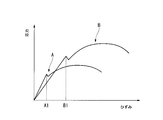
- the stress-strain curve of stainless steel is the stress-strain curve A
- the stress-strain curve of the first member 11 is a stress having an elastic strain limit B1 larger than the elastic strain limit A1.
- -Strain curve B may be used.
- an amorphous alloy which is also called metal glass, ⁇ -titanium, an alloy thereof, and the like can be used as the first metal material.
- the second member 21 is formed of a substantially straight strip metal.
- a first end 21 ⁇ / b> A of each second member 21 is connected to the first member 11.
- the second member 21 extends in a direction away from each other in order to connect to the opening 14.
- the second end portion 21 ⁇ / b> B of each second member 21 is bent inward in the opening / closing direction of the clip body 10 to form a claw portion 22.
- the second member 21 is formed of a metal material (second metal material) having an elastic strain limit smaller than that of the first metal material.
- the Young's modulus of the second metal material may be larger than the Young's modulus of the first metal material.
- the rigidity of the second member 21 is larger than the rigidity of the first metal material.
- stainless steel, cobalt-chromium (Co—Cr) alloy or the like can be used as the material of the second member 21.
- FIG. 2 is an enlarged view of a connection portion between the first member 11 and the second member 21.
- the edge part of the 1st member 11 and the edge part of the 2nd member 21 are firmly joined by the metal bond in the state piled up in the thickness direction. There is no particular limitation on the stacking order when joining.
- the first member 11 and the second member 21 having such a joining mode can be suitably manufactured using a clad material 100 as shown in FIG. 3A, for example. That is, first, a clad material 100 having a two-layer structure in which the material 11a of the first member 11 and the material 21a of the second member 21 are laminated is prepared. Next, as shown in FIG. 3B, the material 11 a in a region having a length necessary for the second member 21 is removed by grinding or the like at both ends of the clad material 100. In the remaining central region, as shown in FIG. 3C, the material 21a is removed by grinding or the like.
- the member 10a is manufactured in which the central region is composed of only the material 11a, and the region of a predetermined length composed of only the member 21a is formed at both ends of the central region.
- the metal material forming each laminated layer is firmly bonded by metal bonding. For this reason, the first member 11 and the second member 21 are hardly separated.
- the end face on the side to which the materials 11a and 21a are connected is formed in a slope shape, but this is not essential. If it does in this way, the stress which acts on a connection site
- the presser tube 30 is formed in a tubular shape with a metal such as stainless steel. As shown in FIG. 1, a tubular fitting portion 31 having an outer diameter smaller than that of the other portion is provided at one end portion of the presser tube 30. The fitting part 31 is used when attaching the hemostatic clip 1 to the indwelling tool 110 mentioned later.
- the inner diameter d1 of the presser tube 30 is larger than the distance 11 between the two parallel portions 13. For this reason, the parallel part 13 can advance and retract within the presser tube 30 without resistance.
- the opening portion 14 at least a part of the distance 12 is larger than the inner diameter d1.
- the surgeon After confirming the bleeding position with an endoscope, the surgeon engages the advancing / retracting member 111 for advancing / retreating the clip body 10 with the bending point 12 and the distal end of the insertion portion of the indwelling tool 110 formed of a coil sheath or the like.
- the fitting portion 31 of the presser tube 30 is inserted into. The surgeon attaches the hemostatic clip 1 to the indwelling tool 110.
- the indwelling device 110 As the indwelling device 110 , a known configuration having an operation unit for hemostatic clip operation at the base end of the long insertion unit can be used.
- the hemostatic clip 1 may be previously attached to the indwelling tool 110 at the time of shipment.
- the surgeon inserts the distal end side of the indwelling tool 110 to which the hemostatic clip 1 is attached into the treatment instrument channel from the forceps opening of the endoscope.
- the surgeon introduces the hemostatic clip 1 to the bleeding site via the endoscope.
- the operator causes the hemostatic clip 1 to protrude from the treatment instrument channel opening at the distal end portion of the endoscope.
- the surgeon moves the hemostatic clip 1 closer to the bleeding site Bt as shown in FIG. 4 while confirming the endoscopic image.
- the surgeon positions the pair of second members 21 so as to sandwich the bleeding site Bt, and then operates the operation portion (not shown) of the indwelling tool 110 to retract the advance / retreat member 111.
- the first member 11 engaged with the advance / retreat member 111 moves backward with respect to the presser tube 30.
- the opening portion 14 of the first member 11 enters the presser tube 30
- the shape of the open portion 14 is defined by the presser tube 30 and elastically deforms so as to approach each other in the presser tube 30.
- the second member 21 connected to the opening 14 also approaches each other.
- the clip body 10 sandwiches the bleeding site Bt. At this point in time, there is a possibility of re-squeezing, so the surgeon holds the operating part in the “temporary ligation” state without allowing the second member 21 to enter the presser tube 30.
- the surgeon checks the endoscopic screen and confirms whether bleeding has stopped. If bleeding is observed even though the bleeding site Bt is temporarily ligated, the operator may operate the operation unit to advance the advance / retreat member 111 because there is a possibility that the hemostatic clip 1 is not properly clamped. . By this operation, the clip body 10 is opened and the ligation of the bleeding site Bt is released.
- the surgeon operates the endoscope and the indwelling tool 110 to adjust the position and orientation of the hemostatic clip 1 with respect to the bleeding site Bt.
- the surgeon tentatively ligates the bleeding site Bt again to check whether the bleeding has stopped.
- the surgeon repeats the same operation a plurality of times as necessary until bleeding is reliably stopped.
- the opening portion 14 Since the first member 11 is made of a metal material having an elastic deformation range wider than that of stainless steel, the opening portion 14 hardly causes plastic deformation even if the opening / closing portion 14 is repeatedly put in and out of the presser tube 30 a plurality of times. Therefore, it is suppressed that the opening width of the opening part 14 becomes narrow as temporary ligation is repeated. When the opening portion 14 comes out of the presser tube 30, the initial opening width of the opening portion 14 as shown in FIG. 4 is suitably maintained.
- the surgeon operates the operation unit to further retract the advance / retreat member 111.
- the second member 21 enters the presser tube 30.
- the advance / retreat member 111 is further retracted, the distal end portion 111A of the advance / retreat member 111 is deformed, and the engagement between the advance / retreat member 111 and the clip body 10 is released.
- the presser tube 30 is detached from the indwelling device 110 and the indwelling of the hemostatic clip 1 is completed.
- the force for ligating the bleeding site Bt is defined by the second member 21 having rigidity higher than that of the first metal material. The For this reason, the hemostatic clip 1 reliably ligates the bleeding site Bt, and the hemostatic state is suitably maintained.
- the hemostatic clip 1 includes the first member 11 formed of a metal material having an elastic deformation range wider than that of stainless steel. For this reason, by allowing the first member 11 to enter the presser tube 30 and performing temporary ligation, even if the temporary ligation is repeated, the first member 11 returns to an almost initial shape and the opening width of the hemostatic clip 1 is reduced. Hateful. As a result, the hemostatic clip 1 can be an easy-to-use hemostatic clip that is easy to re-pinch.
- the second member 21 having rigidity higher than that of the first metal material is connected to the first member 11. For this reason, after temporary ligation is performed under suitable conditions, a part of the second member 21 is accommodated in the presser tube 30 so that the target tissue such as the bleeding site Bt can be reliably ligated with a strong force. it can.
- hemostatic clip 1 it is possible to achieve both ease of re-staking and high ligation force, which is difficult with a single material.
- the first member 11 and the second member 21 are firmly connected by metal bonding. For this reason, the operator can use the hemostatic clip 1 with almost no fear of peeling while using two kinds of materials.
- the clip body may be manufactured without using the above clad material.
- the first member and the second member may be joined by welding. In this case, since both are not connected by a metal bond, the bonding strength is slightly weakened, but a certain effect can be obtained.
- the first member may be formed so that the folding point side is not parallel to the opening portion and is separated from each other with an opening width narrower than the opening portion.
- the first member may be configured such that the opening portion is formed immediately from the vicinity of the bending point.
- the clip body is formed of a first member made of a metal material having an elastic deformation range wider than that of stainless steel, and a metal material having a Young's modulus higher than that of stainless steel, and both ends of the first member You may provide a pair of 2nd member respectively connected to the part.
- the operator can easily re-pinch the target tissue such as a bleeding site and can reliably ligate the target tissue with a strong force. Therefore, it is possible to provide a hemostatic clip that is convenient for the surgeon.
Landscapes
- Health & Medical Sciences (AREA)
- Surgery (AREA)
- Life Sciences & Earth Sciences (AREA)
- Heart & Thoracic Surgery (AREA)
- Nuclear Medicine, Radiotherapy & Molecular Imaging (AREA)
- Vascular Medicine (AREA)
- Engineering & Computer Science (AREA)
- Biomedical Technology (AREA)
- Reproductive Health (AREA)
- Medical Informatics (AREA)
- Molecular Biology (AREA)
- Animal Behavior & Ethology (AREA)
- General Health & Medical Sciences (AREA)
- Public Health (AREA)
- Veterinary Medicine (AREA)
- Surgical Instruments (AREA)
Abstract
この止血クリップは、帯状の部材の中間部を折り曲げて形成されたクリップ本体と、押え管と、を備える。前記クリップ本体は、弾性変形可能な第一金属材料で形成された第一部材と、第一金属材料よりも小さい弾性ひずみ限度を有する第二金属材料で形成され、前記第一部材の両端部にそれぞれ接続された一対の第二部材と、を備える。前記押え管は、前記クリップ本体の一部を前記押え管の内部に収容することにより、前記クリップ本体の開き幅を変化させる。
Description
本発明は、経内視鏡的に体腔内に導入されて使用される止血クリップに関する。より詳しくは、本発明は、対象組織の再結紮が可能な止血クリップに関する。
本願は、2012年7月20日に、米国に出願された仮出願第61/673,964号に基づき優先権を主張し、その内容をここに援用する。
本願は、2012年7月20日に、米国に出願された仮出願第61/673,964号に基づき優先権を主張し、その内容をここに援用する。
従来、消化管等の出血に対し、経内視鏡的に止血クリップを体腔内に導入し、出血箇所をこの止血クリップで挟んで(結紮して)止血することが行われている(例えば、特許文献1参照。)。
このような止血クリップの使用時においては、一度出血箇所を結紮しても出血がうまく止まらないことがある。そのような際にクリップを再度開いて出血箇所をより適切に挟み直すことができると都合がよい。しかしながら、挟む際に押え管等の固定部材に引き込んだクリップの一部は、固定部材との摩擦を生じるため、クリップを再度開くことは容易ではない。
特許文献2には、再結紮が可能な止血クリップが開示されている。この止血クリップでは、固定部材の内部に、固定部材に対してクリップを前進させる向きに付勢する弾性部が設けられている。その結果、クリップを一度固定部材内に引き込んだ後でも比較的容易に押し出せるため、クリップを再度開くことはそれほど困難でない。
特許文献2に記載の止血クリップでは、固定部材内に引き込まれたときに、クリップの一部が閉じ方向に塑性変形する。このため、クリップを固定部材から押し出しても、クリップの開き幅は、引き込み前の大きさとはならず、若干狭くなる。この動作を繰り返すと、クリップの開き幅はさらに狭くなる。その結果、クリップの挟み直しはできるものの、クリップの開き幅が狭いために出血箇所の結紮自体が困難になってしまうという問題がある。
本発明は、出血箇所等の対象組織の挟み直しを繰り返しても、クリップの開き幅が小さくなりにくく、かつ、対象組織を強い力で確実に結紮することができる止血クリップを提供することを目的とする。
本発明の第一の態様によれば、止血クリップは、帯状の部材の中間部を折り曲げて形成されたクリップ本体と、押え管と、を備える。前記クリップ本体は、弾性変形可能な第一金属材料で形成された第一部材と、第一金属材料よりも小さい弾性ひずみ限度を有する第二金属材料で形成され、前記第一部材の両端部にそれぞれ接続された一対の第二部材と、を備える。前記押え管は、前記クリップ本体の一部を前記押え管の内部に収容することにより、前記クリップ本体の開き幅を変化させる。
本発明の第二の態様によれば、前記第一の態様に係る止血クリップにおいて、前記第一部材と前記第二部材とは、金属結合によって接合されていてもよい。
本発明の第三の態様によれば、前記第二の態様に係る止血クリップにおいて、前記クリップ本体は、前記第一部材と前記第二部材とが金属結合された状態で積層された多層金属板の一部を除去加工することにより形成されていてもよい。
上記した止血クリップを用いることで、術者は、簡単に出血箇所等の対象組織の挟み直しをすることができ、かつ、対象組織を強い力で確実に結紮することができる。
本発明の一実施形態に係る止血クリップについて、図1から図7を参照して説明する。本実施形態に係る止血クリップ1は、図1に示すように、クリップ本体10と、押え管30と、を備えている。クリップ本体10は、帯状の部材の中間部を折り曲げて形成され、組織を挟んで結紮する。押え管30は、クリップ本体10の一部が押え管30の内部に収容されることによりクリップ本体10の開き幅を変化させる。
クリップ本体10は、第一部材11と、一対の第二部材21とを備えている。第一部材11は、帯状の金属が長手方向中央部で折り曲げられて形成されている。第二部材21は、第一部材の長手方向両端部に接続されている。
第一部材11は、二つの平行部13と、開き部14とを備えている。二つの平行部13は、折り曲げ点12から互いに平行(略平行を含む)に延びている。開き部14は、各平行部13の一部を屈曲させて形成され、互いに離間するように延びている。
第一部材11は、弾性変形可能な金属材料(第一金属材料)で形成されている。第一金属材料として、止血クリップの一般的な材料であるステンレス鋼(例えば、JISに規定されるSUS304等)よりも降伏強度が大きい金属材料を用いることが好ましい。このような金属材料は、ステンレス鋼よりも広い弾性変形域、すなわちステンレス鋼よりも大きい弾性ひずみ限度を有する。弾性ひずみ限度は、材料の降伏強度をヤング率で割った値である。図7に示すように、例えばステンレス鋼の応力-ひずみ曲線が応力-ひずみ曲線Aである場合、第一部材11の応力-ひずみ曲線は、弾性ひずみ限度A1よりも大きい弾性ひずみ限度B1を有する応力-ひずみ曲線Bであればよい。具体的には、例えば、金属ガラスとも呼ばれる非晶質合金、βチタンおよびその合金等を第一金属材料として用いることができる。
第二部材21は、略直線状の帯状金属で形成されている。各第二部材21の第一の端部21Aが第一部材11に接続されている。第二部材21は、開き部14に接続するため、互いに離間する方向に延びている。各第二部材21の第二の端部21Bは、クリップ本体10の開閉方向内側に折り曲げられ、爪部22を構成している。
第二部材21は、第一金属材料よりも小さい弾性ひずみ限度を有する金属材料(第二金属材料)で形成されている。なお、第二金属材料のヤング率は、第一金属材料のヤング率より大きくてもよい。この場合、第二部材21の剛性は、第一金属材料の剛性よりも大きい。具体的には、ステンレス鋼、コバルト-クロム(Co-Cr)合金等を第二部材21の材料として用いることができる。
図2は、第一部材11と第二部材21との接続部位の拡大図である。第一部材11の端部と第二部材21の端部とは、厚さ方向に重ねられた状態で金属結合により強固に接合されている。接合の際の重ね順については特に制限はない。
このような接合態様の第一部材11および第二部材21は、例えば図3Aに示すようなクラッド材100を用いて好適に製造することができる。すなわち、まず第一部材11の材料11aと第二部材21の材料21aとが積層された二層構造のクラッド材100を準備する。次に、図3Bに示すように、クラッド材100の両端部において、第二部材21として必要な長さの領域の材料11aを研削等で除去する。残った中央部の領域において、図3Cに示すように、材料21aを研削等で除去する。その結果、中央部の領域が材料11aのみから構成され、中央部の領域の両端部に部材21aのみから構成される所定長さの領域が形成された部材10aが製造される。この部材10aを長手方向中央部で折り曲げ、所定の部位を屈曲または折り曲げると、クリップ本体10が完成する。
多層金属板のクラッド材において、積層された各層を形成する金属材料は、金属結合により強固に接合されている。このため、第一部材11と第二部材21とが剥離を起こすことは殆どない。
上述の製造手順例においては、材料11aおよび21aの接続される側の端面が斜面状に形成されているが、これは必須ではない。このようにすると、接続部位に作用する応力が好適に分散され、特定箇所に応力が集中しにくくすることができる。また、材料11aおよび21aのいずれが先に研削されるかは適宜決定されてよい。
押え管30は、ステンレス鋼等の金属で管状に形成されている。図1に示すように、押え管30の一方の端部には、外径が他の部位よりも小さい管状の嵌合部31が設けられている。嵌合部31は、後述する留置具110に止血クリップ1を装着する際に用いられる。
押え管30の内径d1は、2つの平行部13間の距離11よりも大きい。このため、平行部13は、押え管30内を抵抗なく進退することができる。開き部14において、少なくとも一部の距離12が内径d1より大きい。
上記のように構成された本実施形態に係る止血クリップ1の使用時の動作について、消化管出血の止血処置を行う場合を例にとり説明する。
術者は、内視鏡で出血位置を確認した後、クリップ本体10を進退させる進退部材111を折り曲げ点12に係合させた状態で、コイルシース等で形成された留置具110の挿入部の先端に押え管30の嵌合部31を挿入する。術者は、止血クリップ1を留置具110に装着する。
留置具110としては、長尺の挿入部の基端に止血クリップ操作のための操作部を備えた公知の構成のものを用いることができる。出荷時に、留置具110に止血クリップ1が予め装着されている場合もある。
術者は、止血クリップ1が装着された留置具110の先端側を内視鏡の鉗子口から処置具チャンネルに挿入する。術者は、止血クリップ1を内視鏡経由で出血部位まで導入する。術者は、内視鏡先端部の処置具チャンネル開口から止血クリップ1を突出させる。
術者は内視鏡画像を確認しながら、図4に示すように止血クリップ1を出血部位Btに接近させる。術者は、出血部位Btを挟むように一対の第二部材21を位置決めしてから留置具110の操作部(不図示)を操作して、進退部材111を後退させる。これにより、進退部材111に係合された第一部材11が押え管30に対して後退する。第一部材11のうち、開き部14が押え管30内に進入すると、開き部14は押え管30に形状を規定され、押え管30内で互いに接近するように弾性変形する。その結果、開き部14に接続された第二部材21も互いに接近する。図5に示すように、クリップ本体10が出血部位Btを挟む。この時点では、まだ挟み直しをする可能性があるため、術者は第二部材21を押え管30内に進入させず、「仮結紮」の状態で操作部を保持する。
仮結紮の状態で、術者は内視鏡画面を確認し、出血が確実に止まっているかを確認する。出血部位Btを仮結紮しているにもかかわらず出血が見られる場合は、止血クリップ1の挟み方が適切でない可能性があるため、術者は操作部を操作して進退部材111を前進させる。この操作により、クリップ本体10は開いて出血部位Btの結紮は解除される。
術者は、内視鏡や留置具110を操作して、出血部位Btに対する止血クリップ1の位置や向き等を調節する。術者は、再度出血部位Btを仮結紮して、出血が止まったかどうかを確認する。術者は、出血が確実に止められるまで、必要に応じて同様の操作を複数回繰り返す。
第一部材11は、ステンレス鋼よりも広い弾性変形域を有する金属材料で形成されているため、開き部14は、押え管30への出し入れを複数回繰り返しても、塑性変形を起こしにくい。したがって、仮結紮を繰り返すにつれて開き部14の開き幅が狭くなることが抑制される。開き部14が押え管30から出た際には、図4に示すような初期の開き部14の開き幅が好適に保持される。
仮結紮の状態で、出血が止まったことが確認されたら、術者は操作部を操作して、進退部材111をさらに後退させる。これにより、図6に示すように、第二部材21が押え管30内に進入する。さらに進退部材111を後退させると、進退部材111の先端部111Aが変形して、進退部材111とクリップ本体10との係合が解除される。留置具110を後退させると、押え管30が留置具110から外れ、止血クリップ1の留置が完了する。
止血クリップ1が留置された状態では、第二部材21が押え管30と接触しているため、出血部位Btを結紮する力は、第一金属材料以上の剛性を有する第二部材21によって規定される。このため、止血クリップ1は、出血部位Btを確実に結紮し、止血状態が好適に保持される。
上述の特許文献2に記載の止血クリップでは、固定部材内に引き込まれたときに、クリップの一部が閉じ方向に塑性変形する。このため、クリップを固定部材から押し出しても、クリップの開き幅は、引き込み前の大きさとはならず、若干狭くなる。この動作を繰り返すと、クリップの開き幅はさらに狭くなる。その結果、挟み直しはできるものの、開き幅が狭いために出血箇所の結紮自体が困難になってしまうという問題がある。
本実施形態に係る止血クリップ1によれば、ステンレス鋼よりも広い弾性変形域を有する金属材料で形成された第一部材11を備えている。このため、第一部材11を押え管30に進入させて仮結紮をすることにより、仮結紮を繰り返しても、第一部材11がほぼ初期形状に復帰し、止血クリップ1の開き幅が小さくなりにくい。その結果、止血クリップ1を、挟み直しのしやすい、使い勝手の良い止血クリップとすることができる。
第一金属材料以上の剛性を有する第二部材21が第一部材11に接続されている。このため、好適な条件で仮結紮が行われた後、第二部材21の一部を押え管30内に収容することで、出血部位Bt等の対象組織を強い力で確実に結紮することができる。
このように、本実施形態に係る止血クリップ1では、単一材料では困難な、挟み直しのしやすさと高い結紮力との両立が可能である。
第一部材11と第二部材21とは、金属結合により強固に接続されている。このため、2種類の材料を用いながらも、剥離等の心配を殆どせずに、術者は止血クリップ1を使用することができる。
以上、本発明の好ましい実施形態を説明したが、本発明はこれら実施形態に限定されることはない。本発明の趣旨を逸脱しない範囲で、構成の付加、省略、置換、およびその他の変更が可能である。
例えば、上記した止血クリップにおいて、クリップ本体は、上述のクラッド材を用いずに製造されてもよい。例えば、第一部材と第二部材とが溶接によって接合されてもよい。この場合、両者は金属結合で接続されてはいないため、接合強度は若干弱くなるが、一定の効果を得ることができる。
上記した止血クリップにおいて、平行部は必須ではない。したがって、第一部材は、開き部よりも折り曲げ点側が平行でなく、開き部より狭い開き幅で互いに離間するように形成されてもよい。第一部材は、折り曲げ点付近からすぐに開き部が形成されるように構成されてもよい。
上記した止血クリップにおいて、クリップ本体は、ステンレス鋼よりも広い弾性変形域を有する金属材料で形成された第一部材と、ステンレス鋼以上のヤング率を有する金属材料で形成され、第一部材の両端部にそれぞれ接続された一対の第二部材とを備えてもよい。
本発明は前述した説明によって限定されることはなく、添付のクレームの範囲によってのみ限定される。
上記した止血クリップを用いることで、術者は、簡単に出血箇所等の対象組織の挟み直しをすることができ、かつ、対象組織を強い力で確実に結紮することができる。このため、術者にとって使い勝手の良い止血クリップを提供することができる。
A、B 応力-ひずみ曲線
A1、B1 弾性ひずみ限度
Bt 出血部位
d1 内径
l1、l2 距離
1 止血クリップ
10 クリップ本体
10a 部材
11 第一部材
11a、21a 材料
12 折り曲げ点
13 平行部
14 開き部
21 第二部材
21A 第一の端部
21B 第二の端部
22 爪部
30 押え管
31 嵌合部
100 クラッド材
110 留置具
111 進退部材
111A 先端部
A1、B1 弾性ひずみ限度
Bt 出血部位
d1 内径
l1、l2 距離
1 止血クリップ
10 クリップ本体
10a 部材
11 第一部材
11a、21a 材料
12 折り曲げ点
13 平行部
14 開き部
21 第二部材
21A 第一の端部
21B 第二の端部
22 爪部
30 押え管
31 嵌合部
100 クラッド材
110 留置具
111 進退部材
111A 先端部
Claims (3)
- 帯状の部材の中間部を折り曲げて形成されたクリップ本体と、
押え管と、
を備え、
前記クリップ本体は、
弾性変形可能な第一金属材料で形成された第一部材と、
第一金属材料よりも小さい弾性ひずみ限度を有する第二金属材料で形成され、前記第一部材の両端部にそれぞれ接続された一対の第二部材と、
を備え、
前記押え管は、前記クリップ本体の一部を前記押え管の内部に収容することにより、前記クリップ本体の開き幅を変化させる
止血クリップ。 - 請求項1に記載の止血クリップであって、
前記第一部材と前記第二部材とは、金属結合によって接合されている
止血クリップ。 - 請求項2に記載の止血クリップであって、
前記クリップ本体は、前記第一部材と前記第二部材とが金属結合された状態で積層された多層金属板の一部を除去加工することにより形成されている
止血クリップ。
Priority Applications (4)
| Application Number | Priority Date | Filing Date | Title |
|---|---|---|---|
| JP2013552778A JP5480454B1 (ja) | 2012-07-20 | 2013-07-02 | 止血クリップ |
| EP13820622.2A EP2875787B1 (en) | 2012-07-20 | 2013-07-02 | Hemostatic clip |
| CN201380003606.4A CN104023654B (zh) | 2012-07-20 | 2013-07-02 | 止血夹具 |
| US14/273,993 US8894671B2 (en) | 2012-07-20 | 2014-05-09 | Hemostatic clip |
Applications Claiming Priority (2)
| Application Number | Priority Date | Filing Date | Title |
|---|---|---|---|
| US201261673964P | 2012-07-20 | 2012-07-20 | |
| US61/673,964 | 2012-07-20 |
Related Child Applications (1)
| Application Number | Title | Priority Date | Filing Date |
|---|---|---|---|
| US14/273,993 Continuation US8894671B2 (en) | 2012-07-20 | 2014-05-09 | Hemostatic clip |
Publications (1)
| Publication Number | Publication Date |
|---|---|
| WO2014013860A1 true WO2014013860A1 (ja) | 2014-01-23 |
Family
ID=49948692
Family Applications (1)
| Application Number | Title | Priority Date | Filing Date |
|---|---|---|---|
| PCT/JP2013/068089 WO2014013860A1 (ja) | 2012-07-20 | 2013-07-02 | 止血クリップ |
Country Status (5)
| Country | Link |
|---|---|
| US (1) | US8894671B2 (ja) |
| EP (1) | EP2875787B1 (ja) |
| JP (1) | JP5480454B1 (ja) |
| CN (1) | CN104023654B (ja) |
| WO (1) | WO2014013860A1 (ja) |
Families Citing this family (11)
| Publication number | Priority date | Publication date | Assignee | Title |
|---|---|---|---|---|
| US10188392B2 (en) * | 2014-12-19 | 2019-01-29 | Abbott Cardiovascular Systems, Inc. | Grasping for tissue repair |
| US10524912B2 (en) * | 2015-04-02 | 2020-01-07 | Abbott Cardiovascular Systems, Inc. | Tissue fixation devices and methods |
| US10667815B2 (en) | 2015-07-21 | 2020-06-02 | Evalve, Inc. | Tissue grasping devices and related methods |
| JP6274233B2 (ja) * | 2016-02-23 | 2018-02-07 | 住友ベークライト株式会社 | クリップカートリッジシステム |
| US10779837B2 (en) | 2016-12-08 | 2020-09-22 | Evalve, Inc. | Adjustable arm device for grasping tissues |
| CN108567462B (zh) * | 2017-03-07 | 2021-05-11 | 祝建红 | 止血夹 |
| WO2018209313A1 (en) | 2017-05-12 | 2018-11-15 | Evalve, Inc. | Long arm valve repair clip |
| CN111526804B (zh) * | 2018-01-25 | 2023-09-12 | 波士顿科学国际有限公司 | 双支撑钳口设计 |
| AU2019212055B2 (en) | 2018-01-29 | 2021-04-29 | Boston Scientific Scimed, Inc. | Hemostasis clip |
| WO2020121400A1 (ja) * | 2018-12-11 | 2020-06-18 | オリンパス株式会社 | 医療機器、アプリケータ、およびクリップユニット |
| CN111772718B (zh) * | 2020-08-13 | 2022-05-17 | 贝恩医疗设备(湖南)有限公司 | 一种高效止血医疗器械 |
Citations (6)
| Publication number | Priority date | Publication date | Assignee | Title |
|---|---|---|---|---|
| US5713911A (en) * | 1996-10-03 | 1998-02-03 | United States Surgical Corporation | Surgical clip |
| JP2004351211A (ja) * | 2003-05-28 | 2004-12-16 | Ethicon Endo Surgery Inc | 外科クリップ |
| JP2005058627A (ja) * | 2003-08-20 | 2005-03-10 | Pentax Corp | 内視鏡用クリップ装置 |
| JP2006055287A (ja) * | 2004-08-18 | 2006-03-02 | Sumitomo Bakelite Co Ltd | クリップおよびクリップ装置 |
| JP2007196012A (ja) | 2000-10-16 | 2007-08-09 | Olympus Corp | 生体組織のクリップ装置 |
| JP4870139B2 (ja) | 2004-12-24 | 2012-02-08 | オリンパス株式会社 | 結紮装置 |
Family Cites Families (8)
| Publication number | Priority date | Publication date | Assignee | Title |
|---|---|---|---|---|
| DE4319829C1 (de) * | 1993-06-16 | 1994-08-25 | Lerch Karl Dieter | Set zur Behandlung von Gefäßmißbildungen |
| CA2117967A1 (en) * | 1993-10-27 | 1995-04-28 | Thomas W. Sander | Tissue repair device and apparatus and method for fabricating same |
| US6001110A (en) * | 1997-06-20 | 1999-12-14 | Boston Scientific Corporation | Hemostatic clips |
| US6193732B1 (en) * | 1999-01-08 | 2001-02-27 | Cardiothoracic System | Surgical clips and apparatus and method for clip placement |
| US6746461B2 (en) * | 2000-08-15 | 2004-06-08 | William R. Fry | Low-profile, shape-memory surgical occluder |
| US7357805B2 (en) * | 2001-12-13 | 2008-04-15 | Sumitomo Bakelite Company | Clip device for endoscope and clip for endoscope for use therein |
| US6638297B1 (en) * | 2002-05-30 | 2003-10-28 | Ethicon Endo-Surgery, Inc. | Surgical staple |
| WO2012021350A1 (en) * | 2010-08-10 | 2012-02-16 | Cook Medical Technologies Llc | Clip devices and methods of delivery and deployment |
-
2013
- 2013-07-02 EP EP13820622.2A patent/EP2875787B1/en active Active
- 2013-07-02 WO PCT/JP2013/068089 patent/WO2014013860A1/ja active Application Filing
- 2013-07-02 CN CN201380003606.4A patent/CN104023654B/zh active Active
- 2013-07-02 JP JP2013552778A patent/JP5480454B1/ja active Active
-
2014
- 2014-05-09 US US14/273,993 patent/US8894671B2/en active Active
Patent Citations (6)
| Publication number | Priority date | Publication date | Assignee | Title |
|---|---|---|---|---|
| US5713911A (en) * | 1996-10-03 | 1998-02-03 | United States Surgical Corporation | Surgical clip |
| JP2007196012A (ja) | 2000-10-16 | 2007-08-09 | Olympus Corp | 生体組織のクリップ装置 |
| JP2004351211A (ja) * | 2003-05-28 | 2004-12-16 | Ethicon Endo Surgery Inc | 外科クリップ |
| JP2005058627A (ja) * | 2003-08-20 | 2005-03-10 | Pentax Corp | 内視鏡用クリップ装置 |
| JP2006055287A (ja) * | 2004-08-18 | 2006-03-02 | Sumitomo Bakelite Co Ltd | クリップおよびクリップ装置 |
| JP4870139B2 (ja) | 2004-12-24 | 2012-02-08 | オリンパス株式会社 | 結紮装置 |
Non-Patent Citations (1)
| Title |
|---|
| See also references of EP2875787A4 |
Also Published As
| Publication number | Publication date |
|---|---|
| CN104023654B (zh) | 2017-05-17 |
| EP2875787A4 (en) | 2016-03-30 |
| CN104023654A (zh) | 2014-09-03 |
| JP5480454B1 (ja) | 2014-04-23 |
| US20140249553A1 (en) | 2014-09-04 |
| EP2875787B1 (en) | 2018-02-21 |
| JPWO2014013860A1 (ja) | 2016-06-30 |
| EP2875787A1 (en) | 2015-05-27 |
| US8894671B2 (en) | 2014-11-25 |
Similar Documents
| Publication | Publication Date | Title |
|---|---|---|
| JP5480454B1 (ja) | 止血クリップ | |
| JP5435923B2 (ja) | 臓器内穿刺孔封止装置 | |
| JP4059656B2 (ja) | 生体組織のクリップ装置 | |
| CN102727276B (zh) | 一种组织止血夹持装置 | |
| JP6084347B1 (ja) | 内視鏡用処置具 | |
| JP6084346B1 (ja) | クリップ装置 | |
| KR20040084767A (ko) | 외과용 박층 클립 | |
| JP2002224124A (ja) | 結紮装置 | |
| WO2017002438A1 (ja) | 内視鏡用処置具 | |
| JP4709822B2 (ja) | 生体組織のクリップ装置 | |
| JPWO2020122120A1 (ja) | 医療機器、アプリケータ、クリップユニット、およびクリップユニットをリリースする方法 | |
| JP4805293B2 (ja) | 生体組織のクリップ装置 | |
| JP5185977B2 (ja) | 結紮装置 | |
| JP2006187673A (ja) | 結紮装置および内視鏡システム | |
| WO2021084728A1 (ja) | 医療機器 | |
| JP5233401B2 (ja) | クリップ | |
| JP6649830B2 (ja) | 内視鏡用処置具 | |
| WO2021156930A1 (ja) | アプリケータおよび結紮装置 | |
| JP4653184B2 (ja) | 生体組織のクリップ装置 | |
| JP4727074B2 (ja) | 内視鏡用処置具 | |
| JP6038421B1 (ja) | 内視鏡用処置具 | |
| CA3174882A1 (en) | Methods for coupling device components and related devices having such components |
Legal Events
| Date | Code | Title | Description |
|---|---|---|---|
| ENP | Entry into the national phase |
Ref document number: 2013552778 Country of ref document: JP Kind code of ref document: A |
|
| 121 | Ep: the epo has been informed by wipo that ep was designated in this application |
Ref document number: 13820622 Country of ref document: EP Kind code of ref document: A1 |
|
| NENP | Non-entry into the national phase |
Ref country code: DE |
|
| WWE | Wipo information: entry into national phase |
Ref document number: 2013820622 Country of ref document: EP |