WO2014013777A1 - 画像処理装置及び内視鏡装置 - Google Patents
画像処理装置及び内視鏡装置 Download PDFInfo
- Publication number
- WO2014013777A1 WO2014013777A1 PCT/JP2013/063384 JP2013063384W WO2014013777A1 WO 2014013777 A1 WO2014013777 A1 WO 2014013777A1 JP 2013063384 W JP2013063384 W JP 2013063384W WO 2014013777 A1 WO2014013777 A1 WO 2014013777A1
- Authority
- WO
- WIPO (PCT)
- Prior art keywords
- lesion
- pixel
- image processing
- image
- processing apparatus
- Prior art date
Links
- 238000012545 processing Methods 0.000 title claims description 139
- 238000006243 chemical reaction Methods 0.000 claims abstract description 23
- 230000003902 lesion Effects 0.000 claims description 199
- 238000000034 method Methods 0.000 claims description 113
- 230000008569 process Effects 0.000 claims description 103
- 208000025865 Ulcer Diseases 0.000 claims description 30
- 231100000397 ulcer Toxicity 0.000 claims description 30
- 206010061218 Inflammation Diseases 0.000 claims description 25
- 230000004054 inflammatory process Effects 0.000 claims description 25
- 238000010586 diagram Methods 0.000 claims description 18
- 238000003384 imaging method Methods 0.000 claims description 16
- 208000022559 Inflammatory bowel disease Diseases 0.000 claims description 13
- 239000003086 colorant Substances 0.000 claims description 5
- 230000036285 pathological change Effects 0.000 abstract 4
- 231100000915 pathological change Toxicity 0.000 abstract 4
- 238000003780 insertion Methods 0.000 description 18
- 230000037431 insertion Effects 0.000 description 18
- 230000003287 optical effect Effects 0.000 description 17
- 201000010099 disease Diseases 0.000 description 12
- 208000037265 diseases, disorders, signs and symptoms Diseases 0.000 description 12
- 238000004458 analytical method Methods 0.000 description 10
- 230000014509 gene expression Effects 0.000 description 10
- 210000001035 gastrointestinal tract Anatomy 0.000 description 9
- 238000005286 illumination Methods 0.000 description 9
- 238000010191 image analysis Methods 0.000 description 9
- 238000003745 diagnosis Methods 0.000 description 8
- 210000001519 tissue Anatomy 0.000 description 8
- 238000001839 endoscopy Methods 0.000 description 6
- 239000011159 matrix material Substances 0.000 description 6
- 238000012937 correction Methods 0.000 description 5
- 230000035945 sensitivity Effects 0.000 description 4
- 230000006870 function Effects 0.000 description 3
- 210000002429 large intestine Anatomy 0.000 description 3
- 210000004400 mucous membrane Anatomy 0.000 description 3
- 238000012327 Endoscopic diagnosis Methods 0.000 description 2
- 208000037062 Polyps Diseases 0.000 description 2
- 230000008859 change Effects 0.000 description 2
- 230000000295 complement effect Effects 0.000 description 2
- 238000001514 detection method Methods 0.000 description 2
- 238000013507 mapping Methods 0.000 description 2
- 238000012360 testing method Methods 0.000 description 2
- 206010030113 Oedema Diseases 0.000 description 1
- 230000000740 bleeding effect Effects 0.000 description 1
- 210000004204 blood vessel Anatomy 0.000 description 1
- 210000001072 colon Anatomy 0.000 description 1
- 229910052736 halogen Inorganic materials 0.000 description 1
- 150000002367 halogens Chemical class 0.000 description 1
- 230000002008 hemorrhagic effect Effects 0.000 description 1
- 230000006872 improvement Effects 0.000 description 1
- 238000007689 inspection Methods 0.000 description 1
- 230000007774 longterm Effects 0.000 description 1
- QSHDDOUJBYECFT-UHFFFAOYSA-N mercury Chemical compound [Hg] QSHDDOUJBYECFT-UHFFFAOYSA-N 0.000 description 1
- 229910052753 mercury Inorganic materials 0.000 description 1
- 229910001507 metal halide Inorganic materials 0.000 description 1
- 150000005309 metal halides Chemical class 0.000 description 1
- 229910044991 metal oxide Inorganic materials 0.000 description 1
- 150000004706 metal oxides Chemical class 0.000 description 1
- 238000012986 modification Methods 0.000 description 1
- 230000004048 modification Effects 0.000 description 1
- 210000003097 mucus Anatomy 0.000 description 1
- 210000000664 rectum Anatomy 0.000 description 1
- 238000011160 research Methods 0.000 description 1
- 239000004065 semiconductor Substances 0.000 description 1
- 230000003595 spectral effect Effects 0.000 description 1
- 238000001228 spectrum Methods 0.000 description 1
- 230000001360 synchronised effect Effects 0.000 description 1
- 238000012549 training Methods 0.000 description 1
- 210000003384 transverse colon Anatomy 0.000 description 1
- 230000036269 ulceration Effects 0.000 description 1
- 230000000007 visual effect Effects 0.000 description 1
- 229910052724 xenon Inorganic materials 0.000 description 1
- FHNFHKCVQCLJFQ-UHFFFAOYSA-N xenon atom Chemical compound [Xe] FHNFHKCVQCLJFQ-UHFFFAOYSA-N 0.000 description 1
Images


Classifications
-
- A—HUMAN NECESSITIES
- A61—MEDICAL OR VETERINARY SCIENCE; HYGIENE
- A61B—DIAGNOSIS; SURGERY; IDENTIFICATION
- A61B1/00—Instruments for performing medical examinations of the interior of cavities or tubes of the body by visual or photographical inspection, e.g. endoscopes; Illuminating arrangements therefor
- A61B1/00002—Operational features of endoscopes
- A61B1/00004—Operational features of endoscopes characterised by electronic signal processing
- A61B1/00009—Operational features of endoscopes characterised by electronic signal processing of image signals during a use of endoscope
- A61B1/000095—Operational features of endoscopes characterised by electronic signal processing of image signals during a use of endoscope for image enhancement
-
- A—HUMAN NECESSITIES
- A61—MEDICAL OR VETERINARY SCIENCE; HYGIENE
- A61B—DIAGNOSIS; SURGERY; IDENTIFICATION
- A61B1/00—Instruments for performing medical examinations of the interior of cavities or tubes of the body by visual or photographical inspection, e.g. endoscopes; Illuminating arrangements therefor
- A61B1/04—Instruments for performing medical examinations of the interior of cavities or tubes of the body by visual or photographical inspection, e.g. endoscopes; Illuminating arrangements therefor combined with photographic or television appliances
- A61B1/05—Instruments for performing medical examinations of the interior of cavities or tubes of the body by visual or photographical inspection, e.g. endoscopes; Illuminating arrangements therefor combined with photographic or television appliances characterised by the image sensor, e.g. camera, being in the distal end portion
-
- A—HUMAN NECESSITIES
- A61—MEDICAL OR VETERINARY SCIENCE; HYGIENE
- A61B—DIAGNOSIS; SURGERY; IDENTIFICATION
- A61B1/00—Instruments for performing medical examinations of the interior of cavities or tubes of the body by visual or photographical inspection, e.g. endoscopes; Illuminating arrangements therefor
- A61B1/06—Instruments for performing medical examinations of the interior of cavities or tubes of the body by visual or photographical inspection, e.g. endoscopes; Illuminating arrangements therefor with illuminating arrangements
- A61B1/0661—Endoscope light sources
- A61B1/0684—Endoscope light sources using light emitting diodes [LED]
-
- G—PHYSICS
- G06—COMPUTING; CALCULATING OR COUNTING
- G06T—IMAGE DATA PROCESSING OR GENERATION, IN GENERAL
- G06T7/00—Image analysis
- G06T7/0002—Inspection of images, e.g. flaw detection
- G06T7/0012—Biomedical image inspection
-
- H—ELECTRICITY
- H04—ELECTRIC COMMUNICATION TECHNIQUE
- H04N—PICTORIAL COMMUNICATION, e.g. TELEVISION
- H04N9/00—Details of colour television systems
- H04N9/64—Circuits for processing colour signals
-
- G—PHYSICS
- G06—COMPUTING; CALCULATING OR COUNTING
- G06T—IMAGE DATA PROCESSING OR GENERATION, IN GENERAL
- G06T2207/00—Indexing scheme for image analysis or image enhancement
- G06T2207/10—Image acquisition modality
- G06T2207/10024—Color image
-
- G—PHYSICS
- G06—COMPUTING; CALCULATING OR COUNTING
- G06T—IMAGE DATA PROCESSING OR GENERATION, IN GENERAL
- G06T2207/00—Indexing scheme for image analysis or image enhancement
- G06T2207/10—Image acquisition modality
- G06T2207/10068—Endoscopic image
-
- G—PHYSICS
- G06—COMPUTING; CALCULATING OR COUNTING
- G06T—IMAGE DATA PROCESSING OR GENERATION, IN GENERAL
- G06T2207/00—Indexing scheme for image analysis or image enhancement
- G06T2207/30—Subject of image; Context of image processing
- G06T2207/30004—Biomedical image processing
- G06T2207/30028—Colon; Small intestine
Definitions
- the present invention relates to an image processing apparatus for endoscopic diagnosis and a medical endoscopic apparatus including the image processing apparatus, and in particular, acquires information related to a lesion based on color information of a color endoscopic image. It is related with the apparatus provided with the function to display.
- Patent Document 1 Japanese Patent Application Laid-Open No. 2009-106424 describes endoscopic image data captured using white light in order to facilitate identification of blood vessels and lesions.
- Patent Document 1 an electronic endoscope apparatus having a function of performing a color conversion process that emphasizes the difference in color has been proposed.
- the image generated by the electronic endoscope apparatus disclosed in Patent Document 1 is easier to identify a lesioned part or the like than a normal endoscope image.
- the color change at the boundary between the normal mucosal tissue and the lesioned part is continuous, and the color difference from the normal mucosal tissue is slight depending on the type of disease. Therefore, even when the electronic endoscope apparatus disclosed in Patent Document 1 is used, the problem that it is difficult to identify a lesion or the like cannot be solved.
- the image acquisition means for acquiring color endoscope image data, the color space of the color endoscope image data, the HSI color space based on hue, saturation, and luminance, or Color space conversion means for converting to an HSV color space based on hue, saturation, and lightness, and whether or not each pixel constituting the color endoscopic image is a lesion pixel based on hue and saturation
- a lesion pixel determining means for determining a lesion index
- a lesion pixel counting means for counting the number of lesion pixels that is the number of pixels determined to be a lesion part pixel
- a lesion index calculating means for calculating a lesion index based on the number of lesion pixels
- an image processing apparatus comprising a lesion index display means for displaying a lesion index.
- the lesion part is determined in the HSV color space in which the difference between the lesion part and the normal part clearly appears, so that the lesion part and the normal part can be accurately identified.
- objective and quantitative information about the lesion part captured in the endoscopic image for example, the severity of a non-localized disease such as inflammatory bowel disease, a station such as a polyp, etc.
- effective pixel determining means for determining whether the pixel is valid depending on whether the pixel value is within a predetermined range;
- An effective pixel counting unit that counts the number of effective pixels, which is the number of pixels determined to be valid by the determining unit, and whether the lesion pixel determining unit is a pixel of a lesioned part with respect to a pixel determined to be valid Alternatively, the lesion index display means may calculate the lesion index as a ratio of the number of lesion pixels to the number of effective pixels.
- pixels that are not effective for example, pixels with low pixel value accuracy, such as when the pixel value is extremely high or extremely low
- Identification becomes possible.
- the lesion pixel determining means determines whether or not each pixel constituting the color endoscopic image is a pixel of the lesion part for each of a plurality of types of lesions, and the lesion pixel counting means is The number of lesion pixels is counted for each of the plurality of types of lesions, the lesion index calculation means calculates the lesion index for each of the plurality of types of lesions, and the lesion index display means calculates at least one lesion index for the plurality of types of lesions. It is good also as a structure to display.
- the surgeon can obtain detailed information on the state of the disease and can make a more accurate diagnosis.
- the image processing apparatus may further include a total lesion index calculating unit that calculates a total lesion index that is a sum of lesion indexes of a plurality of types of lesions, and the lesion index display unit displays the total lesion index.
- the lesion pixel counting means may count the number of pixels determined to be pixels of any one of a plurality of types of lesions as the number of lesion pixels.
- the image processing apparatus further includes a tone emphasizing unit that performs tone emphasis processing that gives a non-linear gain to the pixel value so that a dynamic range in the vicinity of the boundary of the pixel value region in which the pixel is determined to be a lesioned part is widened.
- the lesion pixel determination unit may be configured to perform determination based on the pixel value after tone enhancement processing.
- the dynamic range in the vicinity of the boundary (threshold value) for determining the lesioned part is widened, so that a more precise determination can be made for the lesioned part.
- the color endoscope image data may be converted into the HSI color space or the HSV color space after being subjected to tone emphasis processing in the RGB color space.
- the tone emphasizing unit may perform tone emphasis processing by applying different gain curves to the luminance values R, G, and B of the primary colors.
- overlay means for performing an overlay process for changing a color of a pixel determined by the lesion pixel determination means as a lesion part
- an overlay image display for displaying an overlay image obtained by performing an overlay process on the color endoscope image And means.
- the overlay image display means may display the color endoscope image and the overlay image at the same time.
- the overlay unit may add a predetermined value corresponding to the type of lesion to the pixel value of the pixel determined as the pixel of the lesion.
- imaging position acquisition means for acquiring information of a position where the color endoscope image is captured, a plurality of positions where the color endoscope image is captured, and the color endoscope image captured at the position It is good also as a structure further provided with the report display means which displays the relationship with a lesion index using at least one of a table
- the report display means may perform print display.
- the lesion may include inflammation and ulcer in inflammatory bowel disease.
- This configuration allows a more accurate diagnosis of the severity of inflammatory bowel disease because the lesion index is a good indicator of the severity of inflammatory bowel disease.
- an endoscope apparatus including the image processing apparatus described above and an endoscope that generates color endoscope image data and outputs the image data to the image processing apparatus.
- FIG. 1 is a block diagram showing a schematic configuration of an electronic endoscope apparatus according to an embodiment of the present invention.
- 1 is a block diagram illustrating a schematic configuration of an image processing unit according to an embodiment of the present invention.
- 3 is a diagram illustrating a schematic configuration of a storage area of an image memory 224.
- FIG. 3 is a diagram illustrating a schematic configuration of a storage area of a memory 226.
- FIG. It is a flowchart which shows the procedure of the process which an image processing unit performs. It is an example of the gain curve used for TE processing. It is a flowchart which shows the procedure of an effective pixel determination process. It is a flowchart which shows the procedure of a lesion determination process.
- FIG. 1 is a block diagram showing a schematic configuration of an electronic endoscope apparatus 1 according to an embodiment of the present invention.
- the electronic endoscope apparatus 1 of this embodiment includes an electronic scope 100, an electronic endoscope processor 200, a monitor 300, and a printer 400.
- the electronic endoscope processor 200 includes a system controller 202 and a timing controller 206.
- the system controller 202 executes various programs stored in the memory 204 and integrally controls the entire electronic endoscope apparatus 1. Further, the system controller 202 changes various settings of the electronic endoscope apparatus 1 in accordance with instructions from the user (surgeon or assistant) input to the operation panel 208.
- the timing controller 206 outputs a clock pulse for adjusting the operation timing of each unit to various circuits in the electronic endoscope apparatus 1.
- the electronic endoscope processor 200 includes a light source device 230 that supplies illumination light, which is a white light beam, to an LCB (Light Carrying Bundle) 102 of the electronic scope 100.
- the light source device 230 includes a lamp 232, a lamp power source 234, a condenser lens 236, and a light control device 240.
- the lamp 232 is a high-intensity lamp that emits illumination light when supplied with driving power from the lamp power supply 234. For example, a xenon lamp, a metal halide lamp, a mercury lamp, or a halogen lamp is used.
- the illumination light emitted from the lamp 232 is collected by the condenser lens 236 and then introduced into the LCB 102 via the light control device 240.
- the light control device 240 is a device that adjusts the amount of illumination light introduced into the LCB 102 based on the control of the system controller 202, and includes a diaphragm 242, a motor 243, and a driver 244.
- the driver 244 generates a drive current for driving the motor 243 and supplies it to the motor 243.
- the diaphragm 242 is driven by a motor 243, and changes the opening through which the illumination light passes to adjust the amount of illumination light passing through the opening.
- the illumination light introduced into the LCB 102 from the incident end propagates through the LCB 102, exits from the exit end of the LCB 102 disposed at the tip of the electronic scope 100, and is irradiated onto the subject via the light distribution lens 104.
- the reflected light from the subject forms an optical image on the light receiving surface of the solid-state image sensor 108 via the objective lens 106.
- the solid-state image sensor 108 is a single-plate color CCD (Charge-Coupled Device) image sensor in which various filters such as an IR (Infra-Red) cut filter 108a and a Bayer array color filter 108b are arranged on the light-receiving surface. Imaging signals of the three primary colors R, G, and B corresponding to the imaged optical image are generated. The generated imaging signal is amplified by a driver signal processing circuit 112 provided in the connection portion of the electronic scope 100, and then converted into an image signal including a luminance signal Y and color difference signals Cb and Cr.
- CCD Charge-Coupled Device
- the image signal converted into the luminance signal Y and the color difference signals Cb and Cr is further converted into a digital signal, and then sent to the image processing unit 220 of the electronic endoscope processor 200.
- the driver signal processing circuit 112 accesses the memory 114 and reads the unique information of the electronic scope 100.
- the unique information of the electronic scope 100 recorded in the memory 114 includes, for example, the number of pixels and sensitivity of the solid-state image sensor 108, an operable frame rate, and the like.
- the driver signal processing circuit 112 outputs the unique information read from the memory 114 to the system controller 202.
- the system controller 202 performs various calculations based on the unique information of the electronic scope 100 and generates a control signal.
- the system controller 202 operates various circuits in the electronic endoscope processor 200 so that processing suitable for the electronic scope 100 connected to the electronic endoscope processor 200 is performed using the generated control signal. And control timing.
- the timing controller 206 supplies clock pulses to the driver signal processing circuit 112 and the image processing unit 220 according to the timing control by the system controller 202.
- the driver signal processing circuit 112 drives and controls the solid-state imaging device 108 at a timing synchronized with the frame rate of the video processed on the electronic endoscope processor 200 side according to the clock pulse supplied from the timing controller 206.
- the image processing unit 220 of the electronic endoscope processor 200 displays an endoscopic image or the like on the monitor based on the image signal sent from the driver signal processing circuit 112 of the electronic scope 100 under the control of the system controller 202.
- Video signal is generated and output to the monitor 300.
- the surgeon performs observation and treatment in the digestive tract, for example, while confirming the endoscopic image displayed on the monitor 300.
- the image processing unit 220 generates a report output signal (print signal) for printing out a report screen, which will be described later, based on the image signal, and outputs the report output signal to the printer 400.
- the electronic endoscope processor 200 is connected to the server 600 via a NIC (Network Interface Card) 210 and a network 500.
- the electronic endoscopic processor 200 acquires information related to the endoscopy (for example, the patient's electronic medical record information and surgeon information) from the server 600 and displays the information on the monitor 300 and the operation panel 208.
- the electronic endoscope processor 200 also transmits and stores endoscopic examination results (endoscopic image data, examination conditions, image analysis results described later, surgeon findings, etc.) to the server 600.
- the electronic endoscope apparatus 1 also has a function of recording still images of a plurality of endoscopic images in association with information on an imaging location (that is, the position (insertion length) of the distal end portion of the electronic scope 100 at the time of imaging). I have. On the outer periphery of the insertion portion 130 of the electronic scope 100, a plurality of optical sensors 132 are provided at equal intervals (for example, at an interval of 5 cm) in the length direction.
- the optical sensor 132 is a light receiving element such as a photodiode, and detects external light (interior lighting in a room in which endoscopy is performed).
- the optical sensor 132 provided in the portion inserted into the digestive tract of the insertion unit 130 does not detect external light, and the optical sensor 132 provided in the portion not inserted in the digestive tract detects external light. Therefore, it is possible to acquire information on the position (insertion length) of the distal end portion of the electronic scope 100 by determining the distribution length of the optical sensor that does not detect light as the length of the insertion portion 130 inserted in the digestive tract. .
- the optical sensor 132 is connected to the driver signal processing circuit 112 and transmits a sensor signal indicating the detected light amount to the driver signal processing circuit 112.
- the driver signal processing circuit 112 calculates the position (insertion length) Pos of the distal end portion of the electronic scope 100 based on the sensor signal from the optical sensor 132.
- an operation signal is transmitted from the operation unit 120 to the driver signal processing circuit 112.
- the system controller 202 acquires a still image acquisition operation signal from the operation unit 120
- the system controller 202 transmits a still image acquisition command to the image processing unit 220 together with the current position information (insertion length) Pos of the distal end of the electronic scope 100.
- the image processing unit 220 a still image of the endoscopic observation image is recorded in association with the position information Pos of the electronic scope 100 at the time of imaging. Details of the process of recording a still image by the image processing unit 220 will be described later.
- FIG. 2 is a block diagram showing a schematic configuration of the image processing unit 220.
- the image processing unit 220 includes a first image processing circuit 222, an image memory 224, a memory 226, and a second image processing circuit 228.
- the first image processing circuit 222 performs various image processing on the image signal from the driver signal processing circuit 112 and outputs the processed image signal to the image memory 224.
- the first image processing circuit 222 includes an RGB conversion unit 222a, a TE processing unit 222b, an effective pixel determination unit 222c, a color space conversion unit 222d, a lesion determination unit (threshold processing unit) 222e, and an overlay processing unit. 222f.
- the second image processing circuit 228 includes a lesion index calculation unit 228a, a display screen generation unit 228b, and a report generation unit 228c. Specific processing performed by each unit of the first image processing circuit 222 and the second image processing circuit 228 will be described later.
- FIG. 3 is a diagram illustrating a schematic configuration of a storage area included in the image memory 224.
- a maximum of seven sets of image data N, tone-enhanced image data E, and overlay image data S can be stored in the image memory 224.
- the image data (normal observation image data N, tone-enhanced image data E, or overlay image data S) output from the image processing circuit 222 is stored in one of the storage area groups P0 to P6 according to the control of the system controller 202. Note that the storage area P0 is overwritten with the image data sequentially output from the first image processing circuit 222, and always holds image data constituting a real-time moving image.
- the image data output from the first image processing circuit 222 is written in P1 to P6 only when a command is issued from the system controller 202. That is, a maximum of six still images are recorded in the image memory 224. Can do.
- FIG. 4 is a diagram illustrating a schematic configuration of a storage area included in the memory 226.
- the memory 226 includes an RGB matrix storage area 226a, a flag storage area 226b, a setting information storage area 226c, and a lesion index storage area group 226d.
- the RGB matrix storage area 226a stores an RGB conversion matrix coefficient M used in an RGB conversion process S1 described later.
- the flag storage area 226b stores a flag table F used for processing in the first image processing circuit 222.
- the flag table F is a numerical table composed of flags f (x, y) indicating analysis results regarding each pixel (x, y) constituting the image data.
- Various setting values used for processing in the image processing unit 220 are recorded in the setting storage area 226c.
- Qk lesion indices IdxR, IdxW, and IdxT, which are analysis results of the images stored in the corresponding storage area group Pk, are recorded.
- the storage area groups P1 and Q1 correspond to the range of the insertion length Pos corresponding to the innermost part of the examination range (for example, near the right colon curve of the transverse colon), and the corresponding insertion length Pos as the k value increases.
- the storage area groups Pk and Qk in which the image data is recorded are determined according to the position information Pos of the image data (the position of the distal end of the electronic scope 100 at the time of imaging).
- the second image processing circuit 228 generates a video signal for monitor display using the image signal stored in the image memory 224 and outputs it to the monitor 300. Further, the second image processing circuit 228 generates a report output signal (print signal) to be described later by using an image signal stored in the image memory 224 and a lesion index (described later) stored in the memory 226 to generate a printer. Output to 400.
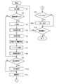
- FIG. 5 is a flowchart showing a procedure of processing performed by the image processing unit 220.
- RGB conversion processing S1 is performed by the RGB conversion unit 222a of the first image processing circuit 222.
- the RGB converter 222a amplifies the luminance signal Y and the color difference signals Cb and Cr sent from the driver signal processing circuit 112, respectively, and then converts them into the three primary color signals R, G, and B.
- the RGB conversion processing S1 is performed using the RGB conversion matrix coefficient M stored in the RGB matrix storage area 226a of the memory 226.
- the RGB conversion matrix coefficient M is set in advance according to the spectral characteristics of the illumination light used for imaging, and simultaneously with the conversion of the signal format from the Y, Cb, Cr signal to the R, G, B signal, the spectrum of the illumination light. The characteristic is corrected.
- the RGB conversion process S1 is completed, the three primary color signals R, G, B of the generated normal observation image data N are output to the image memory 224 and stored in the normal image memory areas 0nR, 0nG, 0nB, respectively.
- the image analysis mode is set (S2).
- color information particularly hue and saturation
- the pixel of the lesioned part is based on a predetermined determination criterion from the analysis result of the color information.
- This is an operation mode in which it is determined whether or not the pixel in the lesion area is identified and displayed.
- the type of lesion to be determined can be selected according to the examination content. Examples described below are observation images of ulcers (white lesions including white lichen and pus-like mucus) and inflammations (red lesions including edema and hemorrhagic bleeding) that are lesions of inflammatory bowel disease (IBD), respectively. Pixels in a specific color gamut are extracted and displayed for identification.
- the electronic endoscope apparatus 1 of the present embodiment is configured to operate in two operation modes: an image analysis mode and a normal observation mode.
- the operation mode is switched by a user operation on the operation unit 120 of the electronic scope 100 or the operation panel 208 of the electronic endoscope processor 200.
- the normal observation mode is set (S2: No)
- the process proceeds to S9.
- a TE process S3 is next performed by the tone emphasis (TE) processing unit 222b.
- the TE processing S3 performs gain adjustment that gives a non-linear gain (gain) to each primary color signal R, G, B in order to increase lesion determination accuracy, and a color gamut peculiar to the lesion to be determined (particularly the boundary portion). )
- This process increases the effective resolution of color expression by substantially expanding the dynamic range in the vicinity.
- the primary color signals R ′, G ′, B ′ (tone enhancement) are given to the primary color signals R, G, B by giving a monotonically increasing nonlinear gain as shown in FIG.
- a process for obtaining the image data E) is performed.
- the boundary area RA and slope of the gain curve is in steepest near the R B.
- the primary color signals G and B may be processed to give the same non-linear gain, and the primary color signal R may be given a non-linear gain different from these.
- the three primary color signals R ′, G ′, B ′ (tone-enhanced image data E) generated by the TE process S3 are output to the image memory 224 and stored in the tone-enhanced image memory areas 0eR, 0eG, 0eB, respectively.
- the TE treatment S3 changes the color of the inflamed part to red, the ulcer part to white, and the normal part to green. Therefore, when the tone-enhanced image data E generated by the TE process S3 is displayed on the monitor 300, the lesioned part (inflamed part or ulcer part) can be easily visually recognized than the normal observation image data N before the TE process S3. it can.
- FIG. 7 is a flowchart showing the procedure of the effective pixel determination process S4.
- the effective pixel determination process S4 shown in FIG. 7 is sequentially performed for all the pixels (x, y) constituting the image data.
- correction is performed from the primary color signals R ′ (x, y), G ′ (x, y), and B ′ (x, y) by the following formula 1.
- Luminance int (x, y) is calculated (S41).
- the corrected luminance int (x, y) is not a simple average of the primary color signals R ′ (x, y), G ′ (x, y), B ′ (x, y), It is obtained as a weighted average based on the specific visual sensitivity characteristics of a human (operator).
- S42 it is determined whether or not the exposure is appropriate (whether the exposure level is necessary for image analysis) (S42).
- S42 it is determined that the exposure is appropriate (S42: Yes) when at least one (or both) of the following two conditions (Expression 2 and Expression 3) is satisfied.
- Equation 2 total light amount
- R ′ (x, y) total light amount
- G ′ (x, y) total light amount
- B total light amount
- a lower limit value of '(x, y) is defined.
- the effective pixel determination unit 222c stores the flag table stored in the flag storage area 226b of the memory 226.
- the value of the flag f (x, y) corresponding to the pixel (x, y) of F is rewritten to “1” (S43).
- the flag f (x, y) takes any flag value from 0 to 3.
- the definition of each flag value is as follows. 0: Invalid pixel data 1: No lesion (normal) or no lesion determined (pixel data valid) 2: Lesions A (inflammation) 3: Lesion B (ulcer)
- the effective pixel determination unit 222c causes the flag f (x , Y) is rewritten to “0” (S44).
- process S45 it is determined whether or not the process has been completed for all the pixels (x, y). The above processes S41 to S45 are repeated until the processing of all the pixels (x, y) is completed.
- the color space conversion unit 222d performs the color space conversion process S5.
- tone-emphasized pixel data in the RGB space defined by the three primary colors of RGB is converted to HSI (Hue-) defined by three elements of hue, saturation, and intensity.
- HSI Hue-
- the data of underexposed or overexposed pixels is inaccurate and reduces the reliability of the analysis results. Therefore, in the color space conversion process S5, the pixel (x, y) in which the value of the flag f (x, y) is set to “1” (that is, determined to be appropriate exposure in the above-described effective pixel determination process S4). Only done about.
- a lesion determination process S6 is performed by the lesion determination unit 222e.
- the lesion determination processing S6 corresponds to each pixel (x, y) of the endoscopic image depending on which of the regions I to III in FIG. 9 to be described later is plotted. This is a process for determining a state (normal, inflammation, ulcer) presumed to be a site.
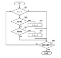
- FIG. 8 is a flowchart showing the procedure of the lesion determination process S6.
- the lesion determination process S6 shown in FIG. 8 is sequentially performed for all the pixels (x, y) constituting the image data.
- the lesion determination process S6 first, it is determined with reference to the flag table F whether or not the data of each pixel (x, y) is valid (S61). If the value of the flag f (x, y) is “1” (pixel data valid), the inflammation determination process S62 is performed next. If the value of the flag f (x, y) is “0” (pixel data invalid), the process advances to step S66 without performing the inflammation determination process S62.
- FIG. 9 plots pixel data (data pairs consisting of hue H (x, y) and saturation S (x, y)) of biological tissue images extracted from endoscopic image data of a plurality of inflammatory bowel disease patients. It is a scatter diagram.
- the scatter diagram of FIG. 9 is divided into a region III surrounded by a broken line on the left side, a region II surrounded by a one-dot chain line below the right side, and a region I other than that.
- most of the pixels of the part judged to be ulcer by a doctor skilled in endoscopic diagnosis of inflammatory bowel disease are plotted in the region III of FIG.
- each pixel value (H (x, y), S (x, y)) is plotted in the region II of FIG. Specifically, when the pixel values (H (x, y), S (x, y)) satisfy the following expressions 4 and 5, they are plotted in the region II (that is, the pixels of the inflamed part). ).
- ⁇ H1 , ⁇ S1, and ⁇ S2 are correction values that can be set by the operator, and the severity (sensitivity) of determination can be appropriately adjusted by setting these correction values.
- each pixel value (H (x, y), S (x, y)) is plotted in the region III of FIG. Specifically, when H (x, y) and S (x, y) satisfy the following Expression 6 or satisfy Expression 7 and Expression 8, the pixel value (H (x, y), It is determined that S (x, y)) is plotted in the region III (that is, the pixel of the ulcer portion).
- ⁇ S3 , ⁇ S4 , ⁇ H2, and ⁇ H3 are correction values that can be set by the operator, and the severity (sensitivity) of determination can be appropriately adjusted by setting these correction values.
- step S66 When the pixel value (H (x, y), S (x, y)) is plotted in the region III (S64: Yes), the value of the flag f (x, y) corresponding to the pixel (x, y) Is rewritten to “3” (ulcer) (S65), and the process proceeds to step S66.
- the pixel values (H (x, y), S (x, y)) are not plotted in the region III (S64: No), it is determined as a normal tissue, and the value “1” of the flag f (x, y) is determined. "(Normal)" is not rewritten, and the process directly proceeds to step S66.
- process S66 it is determined whether or not the process has been completed for all the pixels (x, y). The above processes S61 to S66 are repeated until the processing of all the pixels (x, y) is completed.
- an overlay process S7 is next performed by the overlay processing unit 222f.
- the overlay processing S7 determines the lesion (flag value) so that the pixel determined to be a lesion such as inflammation or ulcer by the lesion determination processing S6 can be easily distinguished from the pixel determined to be normal (has no lesion). This is a process of changing the color to the associated color tone.
- redness is strengthened (specifically, the R component is increased) for pixels determined to be inflamed, and yellowness is increased for pixels determined to be ulcer (specifically, G , B component is increased).
- FIG. 10 is a flowchart showing the procedure of the overlay process S7.
- the overlay process S7 shown in FIG. 10 is sequentially performed for all the pixels (x, y) constituting the normal observation image data N.
- the value of the flag f (x, y) corresponding to each pixel (x, y) is determined with reference to the flag table F (S71, S72, S74).
- the flag table F S71, S72, S74
- the process proceeds directly to S77.
- the values of the primary color signals G ′′ (x, y) and B ′′ (x, y) of the overlay image data S are not changed as they are. (S75), the process proceeds to step S77, and if the value of the flag f (x, y) is “3” (ulcer) (S71: No, S72: No, S74: No), the normal observation image data N A value obtained by adding 100 to the values of the primary color signals G (x, y) and B (x, y) as the values of the primary color signals G ′′ (x, y) and B ′′ (x, y) of the overlay image data S.
- the value of the primary color signal R ′′ (x, y) of the overlay image data S is set (S76), and the process proceeds to S77.
- the three primary color signals R, G, and B of the normal observation image data N are used for the overlay processing S7.
- the primary color signals R ′ (x, y), G ′ (x, y) and B ′ (x, y) may be used. .
- process S77 it is determined whether or not the process has been completed for all the pixels (x, y). The above processes S71 to S77 are repeated until the processing of all the pixels (x, y) is completed.
- the lesion index calculation processing S8 is performed by the lesion index calculation unit 228a of the second image processing circuit 228.
- the lesion index calculation process S8 occupies the number of pixels determined to have a lesion in the lesion determination process S6 out of the number of effective pixels of the endoscope image (the number of pixels determined to be proper exposure in the effective pixel determination process S4). This is a process of calculating a ratio (lesion index).
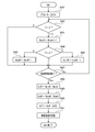
- FIG. 11 is a flowchart showing the procedure of the lesion index calculation process S8.
- each parameter is reset (S81).
- NumO, NumR, and NumW are counters for counting effective pixels, pixels determined to be inflammation, and pixels determined to be ulcer, respectively.
- each pixel (x, y) is a valid pixel (S82). If it is not an effective pixel (S82: 0), the process proceeds to S87 without changing each counter. If it is a valid pixel (S82: 1-3), the valid pixel counter NumO is incremented (S83). Next, it is determined from the value of the flag f (x, y) whether each pixel (x, y) is determined as normal, inflammation, or ulcer (S84). If it is determined to be normal (S84: 1), the process proceeds directly to S87. If it is determined as inflammation (S84: 2), the inflammation counter NumR is incremented (S85), and if it is determined as ulcer (S84: 3), after incrementing the ulcer counter NumW (S86), the process To S87.
- each lesion index IdxR, IdxW, IdxT is recorded in the memory 226, and the lesion index calculation process S8 is completed.
- a determination S9 (FIG. 5) is performed as to whether or not a still image storage command has been issued.
- the image processing unit 220 receives the position information Pos of the distal end portion of the electronic scope 100 together with the still image saving command from the driver signal processing circuit 112 (S9: Yes)
- the normal observation stored in the storage area group P0 of the image memory 224 is performed.
- a copy of the image data N, tone-enhanced image data E, and overlay image data S is stored in one of the storage area groups P1 to P6 corresponding to the position information Pos (S10), and then screen display processing S11 is performed. If there is no still image storage command from the driver signal processing circuit 112 (S9: No), the process proceeds to the screen display process S11 without performing the process S10.
- the next screen display process S11 is a process of generating display screen data to be displayed on the monitor 300, converting it into a video signal and outputting it, and is performed by the display screen generation unit 228b of the second image processing circuit 228.
- the display screen generation unit 228b can generate a plurality of types of display screen data under the control of the system controller 202.
- FIG. 12 is an example of a display screen generated by the screen display process S11, and is an analysis mode observation screen 320 displayed during endoscopic observation in the image analysis mode.
- the analysis mode observation screen 320 includes a date and time display area 321 in which the imaging date and time are displayed, a basic information display area 322 that displays basic information related to the examination (for example, medical chart number, patient name, and operator name), A lesion index display area 323 that displays the lesion indices IdxR, IdxW, and IdxT calculated in the lesion index calculation process S8, a normal image display area 324 that displays normal observation image data N (or tone-enhanced image data E), and an overlay An analysis image display area 325 for displaying image data S (observed image after overlay processing S7) is provided.
- the display screen generation unit 228b reads the real-time lesion indices IdxR, IdxW, and IdxT from the storage area group Q0 of the memory 226 and displays them in the lesion index display area 323.
- “red: 25.8%”, “white: 19.8%” and “detection area: 45.6%” indicate the lesion index of inflammation IdxR, lesion index of ulcer IdxW and total lesion index IdxT, respectively. Display.
- the display screen generation unit 228b reads real-time normal observation image data N (or tone-enhanced image data E) and overlay image data S from the storage area group P0 of the image memory 224, and the normal image display area 324 and the analysis image, respectively. Displayed in the display area 325. Information provided from the system controller 202 is displayed in the date / time display area 321 and the basic information display area 322.
- the surgeon observes the endoscope while looking at the analysis mode observation screen 320. Specifically, while referring to the overlay image data S displayed in the analysis image display area 325, the internal viewing is performed while viewing the normal observation image data N (or tone emphasized image data E) displayed in the normal image display area 324. Make a mirror observation. By particularly carefully observing the colored portion in the overlay image data S, an accurate diagnosis can be performed without overlooking the lesion. Further, by observing with reference to objective and specific numerical values of the lesion indices IdxR, IdxW, and IdxT displayed in the lesion index display area 323, subjective observation received from the normal observation image data N and the overlay image data S This makes it possible to perform more objective and precise diagnosis without being caught by the impression.
- a report output execution command according to the embodiment of the present invention has been received from the system controller 202 (S12).
- the system controller 202 issues an execution command for report output processing S13 described later to the image processing unit. 220. If an execution command for the report output process S13 is issued from the system controller 202 (S12: Yes), the report output process S13 is subsequently performed. If an execution command has not been issued (S12: No), the process proceeds to S14 without performing the report output process S13.
- the report output process S13 is a process for generating a report screen 420 in which endoscopy results are organized, converting the report screen 420 into a report output signal (print signal), outputting the report output signal to the printer 400, and printing the report screen 420.
- the report screen 420 shown in FIG. 13 includes a large intestine model diagram 421, a lesion index list 422, a lesion index distribution diagram 423, a statistical value list 424, and a thumbnail image list 425.
- the large intestine model diagram 421 illustrates the position (observation point) at which a still image is acquired, and a plurality of circles 421b indicating the observation points 1 to 6 are arranged on the schematic diagram 421a of the large intestine.
- the observation points 1 to 6 correspond to the storage area groups P1 to P6 of the image memory 224 and the storage area groups Q1 to Q6 of the memory 226, respectively.
- the lesion index list 422 is a list of total lesion indices IdxT (422c) at the respective observation points 1 to 6 (422b).
- the lesion index distribution diagram 423 is a graph showing the lesion index list 422.
- the statistical value list 424 displays a list of statistical values (average value, variance, standard deviation) of the total lesion index IdxT.
- the thumbnail image list 425 includes the still image thumbnail image 425b of the normal observation image data N (or tone emphasized image data E) acquired at each of the observation points 1 to 6 (425a) and the still image thumbnail image 425c of the overlay image data S.
- the chart number 425d assigned to each normal observation image data N is displayed as a list.
- the lesion is determined in the HSI space, but instead of the HSI space, the HSV (HSB) space based on hue, saturation, and lightness (Value (or Brightness)) is used. It is good also as a structure which performs the determination of a lesion in (1).
- HSV HSV
- the TE process S3 is performed on the RGB space.
- the TE process S3 may be performed on the HSI space after the color space conversion process S5.
- the present invention is not limited to this configuration. It is good also as a structure which acquires the information of an imaging position by the means.
- an optical proximity sensor including a light source and a light receiving element may be provided in the insertion unit 130 of the electronic scope 100.
- sensor light reflected by the inner wall of the digestive tract is detected by the light receiving element, and proximity is detected. Therefore, contrary to the above embodiment, by determining the distribution length of the optical proximity sensor in which the light receiving element detects light as the length of the insertion portion 130 inserted in the digestive tract, the distal end portion of the electronic scope 100 The position information can be acquired.
- a movement amount sensor that detects a movement amount (movement distance and direction) based on the same principle as that of the optical mouse may be provided in the insertion unit 130 of the electronic scope 100. In this case, only one movement amount sensor needs to be provided near the distal end of the insertion portion 130.
- a light source of the optical proximity sensor or the movement amount sensor a light source having an arbitrary wavelength in the range from the near infrared to the visible light region (for example, LD or LED) can be used. High detection accuracy can be obtained by using a light source of a red region having a high reflectance on the tissue surface.
- the position of the distal end portion of the endoscope can be determined by calculating the amount of movement of the distal end portion of the endoscope in the digestive tract by image analysis of the endoscopic image.
- the above embodiment is an example in which the present invention is applied to endoscopy for inflammatory bowel disease, but the present invention can naturally be applied to endoscopy for other diseases.
- the total lesion index IdxT is an index of good severity.
- a disease in which a lesion is localized for example, a polyp
- the closer the tip of the electronic scope is to the lesion the larger the angle of view of the lesion is, and thus the total lesion index IdxT increases. Therefore, the total lesion index IdxT is a good index as to whether or not the lesion is approaching, and oversight of the lesion can be prevented by carefully observing when the total lesion index IdxT starts to increase.
- the total lesion index is calculated from the inflammation lesion index and the ulcer lesion index. Calculated as the sum.
- a value obtained by dividing the number of pixels determined to have any lesion by the number of effective pixels may be used as the total lesion index.
- a still image is recorded by an operator's manual operation.
- the driver signal processing circuit 112 may automatically issue a still image storage command when the camera reaches a preset still image acquisition position (observation point), and the still image may be automatically stored.
- a CCD image sensor is used as the solid-state image sensor 108.
- a configuration using a solid-state image sensor having another configuration such as a CMOS (Complementary Metal Oxide Semiconductor) image sensor may be used.
- CMOS Complementary Metal Oxide Semiconductor
- the solid-state imaging device 108 having the R, G, and B Bayer array color filters 108b is used, but complementary colors Cy (cyan), Mg (magenta), Ye (yellow), A configuration using a solid-state imaging device having a G (green) filter may be used.
Landscapes
- Engineering & Computer Science (AREA)
- Health & Medical Sciences (AREA)
- Life Sciences & Earth Sciences (AREA)
- Surgery (AREA)
- Physics & Mathematics (AREA)
- General Health & Medical Sciences (AREA)
- Medical Informatics (AREA)
- Nuclear Medicine, Radiotherapy & Molecular Imaging (AREA)
- Optics & Photonics (AREA)
- Radiology & Medical Imaging (AREA)
- Heart & Thoracic Surgery (AREA)
- Biomedical Technology (AREA)
- Pathology (AREA)
- Biophysics (AREA)
- Molecular Biology (AREA)
- Animal Behavior & Ethology (AREA)
- Public Health (AREA)
- Veterinary Medicine (AREA)
- Signal Processing (AREA)
- Multimedia (AREA)
- Microelectronics & Electronic Packaging (AREA)
- Quality & Reliability (AREA)
- Computer Vision & Pattern Recognition (AREA)
- General Physics & Mathematics (AREA)
- Theoretical Computer Science (AREA)
- Endoscopes (AREA)
- Image Processing (AREA)
Abstract
カラー内視鏡画像データを取得する画像取得手段と、カラー内視鏡画像データの色空間を、色相、彩度及び輝度を基底とするHSI色空間、又は、色相、彩度及び明度を基底とするHSV色空間に変換する色空間変換手段と、カラー内視鏡画像を構成する各画素について、色相と彩度に基づいて病変部の画素であるか否かを判定する病変画素判定手段と、病変部の画素と判定された画素の数である病変画素数を計数する病変画素計数手段と、病変画素数に基づいて病変指数を計算する病変指数計算手段と、病変指数を表示する病変指数表示手段と、を備える。
Description
本発明は、内視鏡診断用の画像処理装置及び該画像処理装置を備えた医療用の内視鏡装置に関連し、特にカラー内視鏡画像の色情報に基づいて病変部に関する情報を取得して表示する機能を備えた装置に関する。
病変部は、一般に正常な粘膜組織とは異なる色を呈する。カラー内視鏡装置の性能向上により、正常組織とわずかに色の異なる病変部の識別も可能になってきている。しかしながら、術者が内視鏡画像上のわずかな色の相違により正常組織から病変部を正確に識別できるようになるには、熟練者の指導下で長期間のトレーニングを受ける必要があった。また、熟練した術者であっても、わずかな色の違いから病変部を識別することは容易ではなく、慎重な作業が要求されていた。そこで、例えば特開2009-106424号公報(以下、「特許文献1」と記す。)に、血管や病変部の識別を容易にするために、白色光を使用して撮像した内視鏡画像データに対して、色の違いを強調する色変換処理を行う機能を備えた電子内視鏡装置が提案されている。
特許文献1の電子内視鏡装置が生成する画像は、通常の内視鏡画像に比べれば病変部等を識別し易いものといえる。しかし、正常な粘膜組織と病変部等との境界における色の変化は連続的であり、また疾患の種類によっては正常な粘膜組織との色の違いが僅かである。そのため、特許文献1の電子内視鏡装置を使用した場合でも病変部等の識別が難しいという問題は解消されない。また、特許文献1の電子内視鏡装置を使用した場合でも、病変部かどうかの判断は、最終的には術者の経験や知識に依存する読像技能に委ねられており、客観的かつ再現性のある(術者のスキルに依存しない)検査結果を得ることができない。
本発明の実施形態によれば、カラー内視鏡画像データを取得する画像取得手段と、カラー内視鏡画像データの色空間を、色相、彩度及び輝度を基底とするHSI色空間、又は、色相、彩度及び明度を基底とするHSV色空間に変換する色空間変換手段と、カラー内視鏡画像を構成する各画素について、色相と彩度に基づいて病変部の画素であるか否かを判定する病変画素判定手段と、病変部の画素と判定された画素の数である病変画素数を計数する病変画素計数手段と、病変画素数に基づいて病変指数を計算する病変指数計算手段と、病変指数を表示する病変指数表示手段と、を備えた画像処理装置が提供される。
この構成によれば、病変部と正常部の相違が明瞭に現れるHSV色空間において病変部の判定が行われるため、病変部と正常部との正確な判別が可能になる。また、病変指数の表示により、内視鏡画像に写された病変部に関する客観的かつ定量的な情報(例えば、炎症性腸疾患等の非局在型の疾患の重症度や、ポリープ等の局在型の疾患の病変部に近づいているかどうか)を得ることができ、より正確かつ再現性の高い診断が可能になる。
上記の画像処理装置において、カラー内視鏡画像を構成する各画素について、画素値が所定の範囲内にあるか否かにより、画素が有効か否かを判定する有効画素判定手段と、有効画素判定手段により有効と判定された画素の数である有効画素数を計数する有効画素計数手段と、を更に備え、病変画素判定手段が、有効と判定された画素について、病変部の画素であるか否かを判定し、病変指数表示手段が、有効画素数に対する病変画素数の比率として病変指数を計算する構成としてもよい。
この構成によれば、有効でない画素(例えば、画素値が極度に高い場合や、極端に低い場合など、画素値の精度が低い画素)を判定の対象から外すことにより、より正確な病変部の識別が可能になる。
上記の画像処理装置において、病変画素判定手段が、カラー内視鏡画像を構成する各画素が病変部の画素であるか否かを、複数種類の病変についてそれぞれ判定し、病変画素計数手段が、複数種類の病変のそれぞれについて病変画素数を計数し、病変指数計算手段が、複数種類の病変のそれぞれについて病変指数を計算し、病変指数表示手段が、複数種類の病変の少なくとも一つの病変指数を表示する構成としてもよい。
この構成によれば、病変の種類毎の病変指数が表示されるため、術者は疾患の状態に関する詳細な情報が得られ、より正確な診断が可能になる。
上記の画像処理装置において、複数種類の病変の病変指数の合計である総病変指数を計算する総病変指数計算手段を更に備え、病変指数表示手段が総病変指数を表示する構成としてもよい。
この構成によれば、診断が難しい多様な病変を呈する疾患について、術者は客観的かつ総合的な情報を得ることができるため、的確な診断を容易に行うことが可能になる。
上記の画像処理装置において、病変画素計数手段が、複数種類の病変のいずれかの病変部の画素であると判定された画素の数を病変画素数として計数する構成としてもよい。
この構成によれば、画像解析による識別の難しい複数種類の病変を伴う疾患についても、疾患の状態に関する正確な情報を術者に提供することが可能になる。
上記の画像処理装置において、画素が病変部と判定される画素値の領域の境界近傍のダイナミックレンジが広がるように、非線形な利得を画素値に与えるトーン強調処理を行うトーン強調手段を更に備え、病変画素判定手段が、トーン強調処理後の画素値に基づいて判定を行う構成としてもよい。
この構成によれば、病変部の判定の境界(閾値)近傍におけるダイナミックレンジが広げられるため、より精密な判定が病変部の判定が可能になる。
上記の画像処理装置において、カラー内視鏡画像データが、RGB色空間においてトーン強調処理を受けた後、HSI色空間又はHSV色空間に変換される構成としてもよい。
上記の画像処理装置において、トーン強調手段が、各原色の輝度値R、G、Bに対して異なる利得曲線を適用してトーン強調処理を行う構成としてもよい。
この構成によれば、自由度の高いトーン強調処理により、より正確な病変部の判定が可能になる。
上記の画像処理装置において、病変画素判定手段が病変部と判定した画素の色を変更するオーバーレイ処理を行うオーバーレイ手段と、カラー内視鏡画像にオーバーレイ処理を施したオーバーレイ画像を表示するオーバーレイ画像表示手段と、を更に備える構成としてもよい。
この構成によれば、オーバーレイ画像上で病変部と判定された部位が明示されるため、病変部の見落としを防止し、より正確な診断を可能にする。
上記の画像処理装置において、オーバーレイ画像表示手段が、カラー内視鏡画像とオーバーレイ画像とを同時に表示する構成としてもよい。
この構成によれば、オーバーレイ画像と対比することにより、カラー内視鏡画像に写された病変部の識別が容易になる。
上記の画像処理装置において、オーバーレイ手段が、病変部の画素と判定された画素の画素値に、病変の種類に応じた所定値を加算する構成としてもよい。
この構成によれば、種類の異なる病変部が色別表示され、より詳細な疾患の状態に関する情報を、直感的かつ正確に把握することが可能になる。
上記の画像処理装置において、カラー内視鏡画像を撮像した位置の情報を取得する撮像位置取得手段と、カラー内視鏡画像を撮像した複数の位置と、位置において撮像したカラー内視鏡画像の病変指数との関係を、表、グラフ及び模式図の少なくとも一つを用いて表示するレポート表示手段と、を更に備える構成としてもよい。
この構成によれば、疾患の正確な全体像を容易に把握することが可能になる。
上記の画像処理装置において、レポート表示手段が印刷表示を行う構成としてもよい。
上記の画像処理装置において、病変が、炎症性腸疾患における炎症及び潰瘍を含む構成としてもよい。
この構成によれば、病変指数が炎症性腸疾患の重症度の良好な指標となるため、炎症性腸疾患の重症度のより適確な診断を可能にする。
また、本発明の実施形態によれば、上記の画像処理装置と、カラー内視鏡画像データを生成して、画像処理装置に出力する内視鏡と、を備えた内視鏡装置が提供される。
以上のように、本発明の実施形態の構成によれば、病変部と正常部との正確な判別を容易に行うことが可能になる。
以下、本発明の実施の形態について図面を用いて詳細に説明する。
図1は、本発明の実施形態に係る電子内視鏡装置1の概略構成を示すブロック図である。図1に示すように、本実施形態の電子内視鏡装置1は、電子スコープ100、電子内視鏡用プロセッサ200、モニタ300及びプリンタ400を備えている。
電子内視鏡用プロセッサ200は、システムコントローラ202やタイミングコントローラ206を備えている。システムコントローラ202は、メモリ204に記憶された各種プログラムを実行し、電子内視鏡装置1の全体を統合的に制御する。また、システムコントローラ202は、操作パネル208に入力されるユーザ(術者又は補助者)からの指示に応じて、電子内視鏡装置1の各種設定を変更する。タイミングコントローラ206は、各部の動作のタイミングを調整するクロックパルスを電子内視鏡装置1内の各種回路に出力する。
また、電子内視鏡用プロセッサ200は、電子スコープ100のLCB(Light Carrying Bundle)102に白色光束である照明光を供給する光源装置230を備えている。光源装置230は、ランプ232、ランプ電源234、集光レンズ236及び調光装置240を備えている。ランプ232は、ランプ電源234から駆動電力の供給を受けて照明光を放射する高輝度ランプであり、例えば、キセノンランプ、メタルハライドランプ、水銀ランプ又はハロゲンランプが使用される。ランプ232が放射した照明光は、集光レンズ236により集光された後、調光装置240を介してLCB102に導入される。
調光装置240は、システムコントローラ202の制御に基づいてLCB102に導入される照明光の光量を調整する装置であり、絞り242、モータ243及びドライバ244を備えている。ドライバ244は、モータ243を駆動するための駆動電流を生成して、モータ243に供給する。絞り242は、モータ243によって駆動され、照明光が通過する開口を変化させて、開口を通過する照明光の光量を調整する。
入射端からLCB102に導入された照明光は、LCB102内を伝播し、電子スコープ100の先端に配置されたLCB102の出射端から出射して、配光レンズ104を介して被写体に照射される。被写体からの反射光は、対物レンズ106を介して固体撮像素子108の受光面上で光学像を結ぶ。
固体撮像素子108は、IR(Infra Red)カットフィルタ108a、ベイヤ配列カラーフィルタ108bの各種フィルタが受光面に配置された単板式カラーCCD(Charge-Coupled Device)イメージセンサであり、受光面上で結像した光学像に応じた3原色R、G、B各色の撮像信号を生成する。生成された撮像信号は、電子スコープ100の接続部内に設けられたドライバ信号処理回路112において増幅された後、輝度信号Y及び色差信号Cb,Crからなる画像信号に変換される。輝度信号Y及び色差信号Cb,Crに変換された画像信号は、更にデジタル信号に変換された後、電子内視鏡用プロセッサ200の画像処理ユニット220に送られる。また、ドライバ信号処理回路112は、メモリ114にアクセスして電子スコープ100の固有情報を読み出す。メモリ114に記録される電子スコープ100の固有情報には、例えば固体撮像素子108の画素数や感度、動作可能なフレームレート等が含まれる。ドライバ信号処理回路112は、メモリ114から読み出した固有情報をシステムコントローラ202に出力する。
システムコントローラ202は、電子スコープ100の固有情報に基づいて各種演算を行い、制御信号を生成する。システムコントローラ202は、生成した制御信号を用いて、電子内視鏡用プロセッサ200に接続された電子スコープ100に適した処理がなされるように、電子内視鏡用プロセッサ200内の各種回路の動作やタイミングを制御する。
タイミングコントローラ206は、システムコントローラ202によるタイミング制御に従って、ドライバ信号処理回路112及び画像処理ユニット220にクロックパルスを供給する。ドライバ信号処理回路112は、タイミングコントローラ206から供給されるクロックパルスに従って、固体撮像素子108を電子内視鏡用プロセッサ200側で処理される映像のフレームレートに同期したタイミングで駆動制御する。
電子内視鏡用プロセッサ200の画像処理ユニット220は、システムコントローラ202による制御の下、電子スコープ100のドライバ信号処理回路112から送られてくる画像信号に基づいて内視鏡画像等をモニタ表示するためのビデオ信号を生成し、モニタ300に出力する。術者は、モニタ300に表示された内視鏡画像を確認しながら例えば消化管内の観察や治療を行う。また、画像処理ユニット220は、画像信号に基づいて後述するレポート画面を印刷出力するためのレポート出力信号(印刷信号)を生成して、プリンタ400に出力する。
電子内視鏡用プロセッサ200は、NIC(Network Interface Card)210及びネットワーク500を介してサーバ600に接続されている。電子内視鏡用プロセッサ200は、内視鏡検査に関する情報(例えば、患者の電子カルテ情報や術者の情報)をサーバ600から取得してモニタ300や操作パネル208に表示する。電子内視鏡用プロセッサ200はまた、内視鏡検査結果(内視鏡画像データ、検査条件、後述の画像解析結果、術者所見等)をサーバ600に送信して蓄積させる。
また、電子内視鏡装置1は、複数の内視鏡画像の静止画を撮像箇所(すなわち、撮像時の電子スコープ100の先端部の位置(挿入長))の情報と関連付けて記録する機能を備えている。電子スコープ100の挿入部130の外周には、複数の光センサ132が長さ方向に等間隔(例えば5cm間隔)で設けられている。光センサ132は、フォトダイオード等の受光素子であり、外光(内視鏡検査が行われる部屋の室内照明)を検出する。挿入部130の消化管内に挿入され部分に設けられた光センサ132は外光を検出せず、消化管内に挿入されていない部分に設けられた光センサ132は外光を検出する。そのため、光を検出していない光センサの分布長を消化管内に挿入された挿入部130の長さと判定することで、電子スコープ100先端部の位置(挿入長)の情報を取得することができる。光センサ132は、ドライバ信号処理回路112に接続されており、検出した光量を示すセンサ信号をドライバ信号処理回路112に送信する。ドライバ信号処理回路112は、光センサ132からのセンサ信号に基づいて、電子スコープ100の先端部の位置(挿入長)Posを計算する。
また、電子スコープ100の操作部120に対して静止画取得を指示するユーザ操作が行われると、操作部120からドライバ信号処理回路112に操作信号が送信される。システムコントローラ202は、操作部120から静止画取得の操作信号を取得すると、現在の電子スコープ100先端部の位置情報(挿入長)Posと共に静止画取得の指令を画像処理ユニット220に送信する。これにより、画像処理ユニット220において、撮像時の電子スコープ100の位置情報Posと関連付けられて内視鏡観察画像の静止画が記録される。画像処理ユニット220が静止画を記録する処理の詳細は後述する。
図2は、画像処理ユニット220の概略構成を示すブロック図である。画像処理ユニット220は、第1画像処理回路222、画像メモリ224、メモリ226及び第2画像処理回路228を備えている。第1画像処理回路222は、ドライバ信号処理回路112からの画像信号に対して種々の画像処理を施して、画像メモリ224に出力する。
図2に示すように、第1画像処理回路222は、RGB変換部222a、TE処理部222b、有効画素判定部222c、色空間変換部222d、病変判定部(閾値処理部)222e及びオーバーレイ処理部222fを備えている。また、第2画像処理回路228は、病変指数計算部228a、表示画面生成部228b及びレポート生成部228cを備えている。第1画像処理回路222及び第2画像処理回路228の各部が行う具体的な処理については後述する。
図3は、画像メモリ224が備える記憶領域の概略構成を示す図である。本実施形態の画像メモリ224には、7つの記憶領域群Pk(k=0~6)が設けられている。各憶領域群Pkは、通常観察画像データNの3原色信号R,G,Bをそれぞれ記憶する通常画像メモリ領域knR,knG,knB(k=0~6)と、後述するTE処理S3により生成されるトーン強調画像データEの原色信号R’,G’,B’をそれぞれ記憶するトーン強調画像メモリ領域keR,keG,keB(k=0~6)と、後述するオーバーレイ処理S7により生成されるオーバーレイ画像データSの3原色信号R”,G”,B”をそれぞれ記憶するオーバーレイ画像メモリ領域ksR,ksG,ksB(k=0~6)を備えている。すなわち、画像メモリ224は、通常観察画像データNとトーン強調画像データEとオーバーレイ画像データSのデータセットを最大7セット記憶することができる。画像メモリ224は、第1画像処理回路222から出力された画像データ(通常観察画像データN、トーン強調画像データE又はオーバーレイ画像データS)を、システムコントローラ202の制御に従い、記憶領域群P0~P6のいずれかに記憶させるように構成されている。なお、記憶領域P0には、第1画像処理回路222から順次出力される画像データが上書きされ、常にリアルタイムの動画を構成する画像データが保持される。一方、記憶領域群P1~P6には、システムコントローラ202から指令があった時にのみ、第1画像処理回路222から出力された画像データが書き込まれる。すなわち、画像メモリ224には最大6枚の静止画を記録することができる。
図4は、メモリ226が備える記憶領域の概略構成を示す図である。メモリ226は、RGBマトリクス記憶領域226a、フラグ記憶領域226b、設定情報記憶領域226c及び病変指数記憶領域群226dを備えている。RGBマトリクス記憶領域226aには後述するRGB変換処理S1において使用されるRGB変換マトリクス係数Mが格納される。また、フラグ記憶領域226bには第1画像処理回路222での処理に使用されるフラグテーブルFが格納される。なお、フラグテーブルFは、画像データを構成する各画素(x,y)に関する解析結果を示すフラグf(x,y)から構成された数値テーブルである。設定記憶領域226cには、画像処理ユニット220での処理に使用される各種設定値が記録されている。また、病変指数記憶領域群226dには、画像メモリ224の記憶領域群Pk(k=0~6)に対応する7つの記憶領域群Qk(k=0~6)が設けられている。各記憶領域群Qkには、対応する記憶領域群Pkに記憶された画像の解析結果である病変指数IdxR、IdxW、IdxTが記録される。
なお、記憶領域群Pk及びQk(k=1~6)は、それぞれ電子スコープ100の先端部の位置情報(挿入長)Posの値と関連付けられている。具体的には、記憶領域群P1及びQ1は検査範囲の最奥部(例えば横行結腸の右結腸曲付近)に相当する挿入長Posの範囲に対応し、k値が大きくなるほど対応する挿入長Posが短くなり、記憶領域群P6及びQ6が直腸付近に相当する挿入長Posの範囲に対応する。すなわち、検査範囲の最奥部から電子スコープ100の挿入部130を引き抜きながら静止画を取得していくと、取得した順にk=1~6の記憶領域に静止画が記録される。位置情報Posと記憶領域群Pk、Qk(k=1~6)との対応関係を規定する設定情報は、設定情報記憶領域226cに記録されている。画像データが記録される記憶領域群Pk、Qkは、画像データの位置情報Pos(撮像時の電子スコープ100先端部の位置)に応じて決定される。
第2画像処理回路228は、画像メモリ224に記憶された画像信号を使用してモニタ表示用のビデオ信号を生成し、モニタ300に出力する。また、第2画像処理回路228は、画像メモリ224に記憶された画像信号やメモリ226に記憶される病変指数(後述)を使用して、後述するレポート出力信号(印刷信号)を生成してプリンタ400に出力する。
次に、画像処理ユニット220が行う処理の詳細を説明する。図5は、画像処理ユニット220が行う処理の手順を示すフローチャートである。画像処理ユニット220の処理が開始すると、先ず、第1画像処理回路222のRGB変換部222aによりRGB変換処理S1が行われる。RGB変換処理S1では、RGB変換部222aが、ドライバ信号処理回路112から送られてくる輝度信号Y及び色差信号Cb,Crをそれぞれ増幅した後、3原色信号R,G,Bに変換する。RGB変換処理S1は、メモリ226のRGBマトリクス記憶領域226aに格納されたRGB変換マトリクス係数Mを使用して行われる。RGB変換マトリクス係数Mは、撮像に用いる照明光のスペクトル特性に応じて予め設定されており、Y,Cb,Cr信号からR,G,B信号への信号形式の変換と同時に、照明光のスペクトル特性の補正が行われる。また、RGB変換処理S1が完了すると、生成された通常観察画像データNの3原色信号R,G,Bは画像メモリ224に出力され、それぞれ通常画像メモリ領域0nR,0nG,0nBに記憶される。
次に、画像解析モードに設定されているか否かが判断される(S2)。本発明の実施形態に係る画像解析モードは、画像データの各画素について色情報(特に色相及び彩度)を解析し、色情報の解析結果から所定の判定基準に基づいて病変部の画素であるか否かを判定し、病変部の画素を識別表示する動作モードである。判定する病変の種類は、検査内容に応じて選択することができる。以下に説明する例は、炎症性腸疾患(IBD)の病変である潰瘍(白苔や膿様粘液を含む白色病変)及び炎症(浮腫や易出血性を含む赤変病変)の観察像にそれぞれ特有の色域にある画素を抽出して、識別表示するものである。
なお、本実施形態の電子内視鏡装置1は、画像解析モードと通常観察モードの2つの動作モードで動作するように構成されている。動作モードは、電子スコープ100の操作部120や電子内視鏡用プロセッサ200の操作パネル208に対するユーザ操作によって切り換えられる。通常観察モードに設定されている場合は(S2:No)、処理はS9に進む。
画像解析モードが選択されている場合は(S2:Yes)、次にトーン強調(TE)処理部222bによるTE処理S3が行われる。TE処理S3は、病変の判定精度を上げるために、各原色信号R,G,Bに対して非線形なゲイン(利得)を与えるゲイン調整を行い、判定する病変に特有の色域(特に境界部)付近におけるダイナミックレンジを実質的に広げて、色表現の実効的な分解能を高める処理である。具体的には、TE処理S3では、各原色信号R,G,Bに対して、図6に示すような単調増加の非線形のゲインを与えて原色信号R’,G’,B’(トーン強調画像データE)を取得する処理が行われる。例えば、潰瘍に特有な色域の境界のR空間への写像を境界領域RAとし、炎症に特有な色域の境界のR空間への写像を境界領域RBとすると、境界領域RA及びRBの付近においてゲイン曲線の傾きが最も急峻になっている。このようなゲイン曲線に従ってゲインを与えることにより、境界領域RA及びRBの付近における原色信号R’(原色信号Rに対してTE処理S3を施した信号)の実質的なダイナミックレンジを広げることができ、より精密な閾値判定が可能になる。
ここで、各原色信号R,G,Bに対してそれぞれ異なるゲイン調整を行ってもよい。さらにまた、各原色信号G,Bは同じ非線形のゲインを与え、原色信号Rにはこれらとは異なる非線形のゲインを与える処理であってもよい。また、TE処理S3により生成された3原色信号R’,G’,B’(トーン強調画像データE)は、画像メモリ224に出力され、それぞれトーン強調画像メモリ領域0eR,0eG,0eBに記憶される。
なお、TE処理S3により、炎症部が赤く、潰瘍部が白く、正常部が緑色に色味が変化する。そのため、TE処理S3により生成されたトーン強調画像データEをモニタ300に表示した場合、TE処理S3前の通常観察画像データNよりも病変部(炎症部や潰瘍部)を容易に視認することができる。
TE処理S3が完了すると、次にトーン強調画像データEに対して有効画素判定部222cによる有効画素判定処理S4が行われる。図7は、有効画素判定処理S4の手順を示すフローチャートである。図7に示す有効画素判定処理S4は、画像データを構成する全ての画素(x,y)について順次行われる。有効画素判定処理S4では、まず各画素(x,y)について、原色信号R’(x,y),G’(x,y),B’(x,y)から、下記の式1により補正輝度int(x,y)が計算される(S41)。
(式1)

なお、計算した補正輝度int(x,y)の値は、後述する適正露出判定S42に使用される。また、式1から分かるように、補正輝度int(x,y)は、原色信号R’(x,y),G’(x,y),B’(x,y)の単純平均ではなく、ヒト(術者)の比視感度特性に基づいた加重平均として求められる。
次に、各画素について、処理S41において計算したトーン強調画像データEの補正輝度int(x,y)及び原色信号R’(x,y),G’(x,y),B’(x,y)に基づいて、露出の適否(画像解析に必要な露出レベルか否か)を判定する(S42)。適正露出判定S42では、次の2つの条件(式2、式3)の少なくとも一方(或いは両方)を満たす場合に、適正露出(S42:Yes)と判定する。なお、式2により補正輝度int(x,y)(全体の光量)の上限値が規定されており、式3により各原色信号R’(x,y),G’(x,y),B’(x,y)の下限値が規定されている。
(式2)

(式3)

画素(x,y)について、式2又は式3を満たし、適正露出と判定されると(S42:Yes)、有効画素判定部222cは、メモリ226のフラグ記憶領域226bに格納されているフラグテーブルFの画素(x,y)に対応するフラグf(x,y)の値を「1」に書き換える(S43)。なお、フラグf(x,y)は、0~3のいずれかのフラグ値をとる。各フラグ値の定義は以下の通りである。
0:画素データ無効
1:病変無し(正常)又は病変未判定(画素データ有効)
2:病変A(炎症)
3:病変B(潰瘍)
0:画素データ無効
1:病変無し(正常)又は病変未判定(画素データ有効)
2:病変A(炎症)
3:病変B(潰瘍)
また、適正露出判定S42において、式2、式3のいずれの条件も満たさず、露出不適正と判定されると(S42:No)、有効画素判定部222cは、フラグテーブルFのフラグf(x,y)の値を「0」に書き換える(S44)。
次に、処理S45では、全ての画素(x,y)について処理が完了したかどうかが判定される。全ての画素(x,y)の処理が完了するまで、上記の処理S41~S45が繰り返される。
有効画素判定処理S4が完了すると、次に色空間変換部222dにより色空間変換処理S5が行われる。色空間変換処理S5は、RGB3原色で定義されるRGB空間のトーン強調された画素データを、色相(Hue)・彩度(Saturation)・輝度(Intensity)の3要素で定義されるHSI(Hue-Saturation-Intensity)空間の画素データに変換する処理である。具体的には、色空間変換処理S5において、トーン強調画像データEの各画素(x,y)の原色信号R’(x,y),G’(x,y),B’(x,y)が、色相H(x,y),彩度S(x,y),輝度I(x,y)に変換される。なお、本実施形態では、以降の処理において輝度I(x,y)が使用されないため、輝度I(x,y)の計算は行わず、色相H(x,y)及び彩度S(x,y)のみを計算して処理効率を高めている。
また、露出が不足又は過剰な画素のデータは精度が低く、解析結果の信頼度を下げてしまう。そのため、色空間変換処理S5は、フラグf(x,y)の値が「1」に設定された(すなわち、上述の有効画素判定処理S4において適正露出と判定された)画素(x,y)についてのみ行われる。
色空間変換処理S5が完了すると、次に病変判定部222eにより病変判定処理S6が行われる。本発明の実施形態に係る病変判定処理S6は、内視鏡画像の各画素(x,y)について、後述する図9の領域I~IIIのいずれにプロットされるかによって、その画素に対応する部位に推測される状態(正常、炎症、潰瘍)を判定する処理である。
図8は、病変判定処理S6の手順を示すフローチャートである。図8に示す病変判定処理S6は、画像データを構成する全ての画素(x,y)について順次行われる。病変判定処理S6では、まず、フラグテーブルFを参照して、各画素(x,y)のデータが有効か否かを判断する(S61)。フラグf(x,y)の値が「1」(画素データ有効)であれば、次に炎症判定処理S62を行う。また、フラグf(x,y)の値が「0」(画素データ無効)であれば、炎症判定処理S62を行わずに、処理S66へ進む。
ここで、炎症判定処理S62及び後述する潰瘍判定処理S64について説明する。図9は、複数の炎症性腸疾患患者の内視鏡画像データから抽出した生体組織像の画素データ(色相H(x,y)と彩度S(x,y)からなるデータ対)をプロットした散布図である。図9の散布図は、左側の破線で囲まれた領域III、右側下方の一点鎖線で囲まれた領域II、及びそれ以外の領域Iに区分される。本発明者の研究により、炎症性腸疾患の内視鏡診断に熟練した医師によって潰瘍と判断された部位の画素の大半が図9の領域IIIにプロットされ、炎症と判断された部位の画素の大半が図9の領域IIにプロットされ、正常と判断された部位の画素の大半が領域Iにプロットされることが判明した。このことは、生体組織を撮像した内視鏡観察像の色相(色合い)と彩度(鮮やかさ)の2つの情報により、生体組織の状態(潰瘍や炎症)を高い精度で判別できることを意味している。
炎症判定処理S62においては、各画素値(H(x,y),S(x,y))が、図9の領域IIにプロットされるか否かが判定される。具体的には、画素値(H(x,y),S(x,y))が、以下の式4及び式5を満たす場合に、領域IIにプロットされる(すなわち炎症部の画素である)と判定される。なお、δH1、δS1及びδS2は、術者によって設定可能な補正値であり、これらの補正値の設定によって判定の厳しさ(感度)等を適宜調整することができる。
(式4)

(式5)

画素値(H(x,y),S(x,y))が領域IIにプロットされる場合は(S62:Yes)、画素(x,y)に対応するフラグf(x,y)の値が「2」(炎症)に書き換えられ(S63)、処理S66に進む。また、画素値(H(x,y),S(x,y))が領域IIにプロットされない場合は(S62:No)、続いて潰瘍判定処理S64が行われる。
潰瘍判定処理S64では、各画素値(H(x,y),S(x,y))が、図9の領域IIIにプロットされるか否かが判定される。具体的には、H(x,y)、S(x,y)が、以下の式6を満たすか、若しくは、式7及び式8を満たす場合に、画素値(H(x,y),S(x,y))が領域IIIにプロットされる(すなわち潰瘍部の画素である)と判定される。なお、δS3、δS4、δH2及びδH3は術者によって設定可能な補正値であり、これらの補正値の設定によって判定の厳しさ(感度)等を適宜調整することができる。
(式6)

(式7)

(式8)

画素値(H(x,y),S(x,y))が領域IIIにプロットされる場合は(S64:Yes)、画素(x,y)に対応するフラグf(x,y)の値が「3」(潰瘍)に書き換えられ(S65)、処理S66に進む。また、画素値(H(x,y),S(x,y))が領域IIIにプロットされない場合は(S64:No)、正常組織と判定され、フラグf(x,y)の値「1」(正常)は書き換えられず、そのまま処理S66に進む。
処理S66では、全ての画素(x,y)について処理が完了したかどうかが判定される。全ての画素(x,y)の処理が完了するまで、上記の処理S61~S66が繰り返される。
病変判定処理S6が完了すると、次にオーバーレイ処理部222fにより本発明の実施形態に係るオーバーレイ処理S7が行われる。オーバーレイ処理S7は、病変判定処理S6により炎症や潰瘍といった病変部と判定された画素について、正常(病変を有しない)と判定された画素と容易に識別できるように、その病変(フラグ値)と関連付けられた色調に色を変更する処理である。本実施形態では、炎症と判定された画素に対して赤みを強め(具体的には、R成分を増加させ)、潰瘍と判定された画素に対して黄みを強める(具体的には、G、B成分を増加させる)処理が行われる。
図10は、オーバーレイ処理S7の手順を示すフローチャートである。図10に示すオーバーレイ処理S7は、通常観察画像データNを構成する全ての画素(x,y)について順次行われる。オーバーレイ処理S7では、まずフラグテーブルFを参照して、各画素(x,y)に対応するフラグf(x,y)の値を判断する(S71、S72、S74)。フラグf(x,y)の値が「0」(画素データ無効)の場合は(S71:Yes)、直接処理S77へ進む。フラグf(x,y)の値が「1」(正常)の場合は(S71:No、S72:Yes)、通常観察画像データNの原色信号R(x,y),G(x,y),B(x,y)をそのまま変更せずにオーバーレイ画像データSの原色信号R”(x,y),G”(x,y),B”(x,y)の値として(S73)、処理S77へ進む。フラグf(x,y)の値が「2」(炎症)の場合は(S71:No、S72:No、S74:Yes)、通常観察画像データNの原色信号R(x,y)の値に100を加えたものをオーバーレイ画像データSの原色信号R”(x,y)の値とし、通常観察画像データNの原色信号G(x,y)及びB(x,y)の値をそのまま変更せずにオーバーレイ画像データSの原色信号G”(x,y)及びB”(x,y)の値として(S75)、処理S77へ進む。また、フラグf(x,y)の値が「3」(潰瘍)の場合は(S71:No、S72:No、S74:No)、通常観察画像データNの原色信号G(x,y)及びB(x,y)の値にそれぞれ100を加えたものをオーバーレイ画像データSの原色信号G”(x,y)及びB”(x,y)の値とし、通常観察画像データNの原色信号R(x,y)の値をそのまま変更せずにオーバーレイ画像データSの原色信号R”(x,y)の値として(S76)、処理S77へ進む。ここで、本実施形態のオーバーレイ処理S7には通常観察画像データNの3原色信号R,G,Bを用いているが、別の実施形態では、トーン強調画像データEの原色信号R’(x,y),G’(x,y)およびB’(x,y)を用いてもよい。
処理S77では、全ての画素(x,y)について処理が完了したかどうかが判定される。全ての画素(x,y)の処理が完了するまで、上記の処理S71~S77が繰り返される。
オーバーレイ処理S7が完了すると、オーバーレイ処理S7により生成されたオーバーレイ画像データSが、画像メモリ224に出力され、それぞれオーバーレイ画像メモリ領域0sR,0sG,0sB(k=0~6)に記憶される。
次に、第2画像処理回路228の病変指数計算部228aにより本発明の実施形態に係る病変指数計算処理S8が行われる。病変指数計算処理S8は、内視鏡画像の有効画素数(有効画素判定処理S4において適正露出と判定された画素数)のうち、病変判定処理S6において病変を有すると判定された画素数の占める割合(病変指数)を計算する処理である。
図11は、病変指数計算処理S8の手順を示すフローチャートである。病変指数計算処理S8では、まず各パラメータをリセットする(S81)。なお、NumO、NumR及びNumWは、それぞれ有効画素、炎症と判定された画素及び潰瘍と判定された画素を計数するカウンタである。
次に、フラグテーブルFを参照して、各画素(x,y)が有効画素であるか否かが判断される(S82)。有効画素ではない場合は(S82:0)、各カウンタを変更せずに処理をS87に進める。有効画素である場合は(S82:1-3)、有効画素カウンタNumOをインクリメントする(S83)。次に、フラグf(x,y)の値から、各画素(x,y)が正常、炎症、潰瘍のいずれに判定されているかが判断される(S84)。正常と判定されていれば(S84:1)、そのまま処理をS87に進める。また、炎症と判定されていれば(S84:2)、炎症カウンタNumRをインクリメントし(S85)、潰瘍と判定されていれば(S84:3)、潰瘍カウンタNumWをインクリメントした後(S86)、処理をS87に進める。
次に、全ての画素(x,y)について処理が完了したかどうかが判定される(S87)。全ての画素(x,y)の処理が完了するまで、上記の処理S81~S87が繰り返される。
全ての画素(x,y)についてカウントが完了すると、次に、炎症の病変指数IdxRが計算される(S88)。炎症の病変指数IdxRは、全有効画素数に占める炎症と判定された画素数の割合であり、IdxR=NumR/NumOにより計算される。
次に、潰瘍の病変指数IdxWが計算される(S89)。潰瘍の病変指数IdxWは、全有効画素数に占める潰瘍と判定された画素数の割合であり、IdxW=NumW/NumOにより計算される。
次に、総病変指数IdxTが計算される(S90)。総病変指数IdxTは、全有効画素数に占める、病変(炎症又は潰瘍)と判定された画素数の割合であり、IdxT=IdxR+IdxWにより計算される。本発明者の研究により、炎症性腸疾患の内視鏡画像の総病変指数IdxTと炎症性腸疾患の重症度を示すMayoスコアとの間に強い相関があり、総病変指数IdxTが炎症性腸疾患の重症度を簡易的に判定するための良い指標となることが明らかにされている。
次に、メモリ226に各病変指数IdxR、IdxW、IdxTを記録して、病変指数計算処理S8が終了する。
次に、静止画保存の指令が出されているか否かの判定S9(図5)が行われる。画像処理ユニット220は、ドライバ信号処理回路112から静止画保存の指令と共に電子スコープ100先端部の位置情報Posを受け取ると(S9:Yes)、画像メモリ224の記憶領域群P0に記憶された通常観察画像データN、トーン強調画像データE及びオーバーレイ画像データSの複製を、位置情報Posに対応する記憶領域群P1~6のいずれかに記憶させ(S10)、次いで画面表示処理S11が行われる。ドライバ信号処理回路112から静止画保存の指令が無ければ(S9:No)、処理S10を行わずに画面表示処理S11に進む。
次の画面表示処理S11は、モニタ300に表示するための表示画面データを生成し、ビデオ信号に変換して出力する処理であり、第2画像処理回路228の表示画面生成部228bによって行われる。表示画面生成部228bは、システムコントローラ202の制御に応じて、複数種類の表示画面データを生成することができる。
図12は、画面表示処理S11によって生成される表示画面の一例であり、画像解析モードでの内視鏡観察中に表示される解析モード観察画面320である。解析モード観察画面320は、撮像日時が表示される日時表示領域321と、検査に関連する基本的な情報(例えば、カルテ番号、患者名、術者名)を表示する基本情報表示領域322と、病変指数計算処理S8において計算された病変指数IdxR、IdxW、IdxTを表示する病変指数表示領域323と、通常観察画像データN(又はトーン強調画像データE)を表示する通常画像表示領域324と、オーバーレイ画像データS(オーバーレイ処理S7後の観察画像)を表示する解析画像表示領域325を備えている。
画面表示処理S11において、表示画面生成部228bは、メモリ226の記憶領域群Q0からリアルタイムの病変指数IdxR、IdxW、IdxTを読み取り、病変指数表示領域323に表示する。図12中の「赤:25.8%」、「白:19.8%」及び「検出面積:45.6%」は、それぞれ炎症の病変指数IdxR、潰瘍の病変指数IdxW及び総病変指数IdxTの表示である。また、表示画面生成部228bは、画像メモリ224の記憶領域群P0からリアルタイムの通常観察画像データN(又はトーン強調画像データE)及びオーバーレイ画像データSを読み取り、それぞれ通常画像表示領域324及び解析画像表示領域325に表示する。また、日時表示領域321及び基本情報表示領域322には、システムコントローラ202から提供された情報が表示される。
術者は、解析モード観察画面320を見ながら内視鏡観察を行う。具体的には、解析画像表示領域325に表示されるオーバーレイ画像データSを参照しつつ、通常画像表示領域324に表示される通常観察画像データN(又はトーン強調画像データE)を見ながら内視鏡観察を行う。オーバーレイ画像データSにおいて色付けされた部位について特に慎重に観察を行うことで、病変部を見落とすことなく、正確な診察を行うことができる。また、病変指数表示領域323に表示される病変指数IdxR、IdxW、IdxTの客観的かつ具体的な数値を参照しながら観察することにより、通常観察画像データNやオーバーレイ画像データSから受ける主観的な印象に囚われず、より客観的かつ緻密な診断を行うことが可能になる。
次に、システムコントローラ202から本発明の実施形態に係るレポート出力の実行指令を受けたか否かが判断される(S12)。電子スコープ100の操作部120や電子内視鏡用プロセッサ200の操作パネル208に対するユーザ操作によりレポート出力の実行が指示されると、システムコントローラ202は後述するレポート出力処理S13の実行指令を画像処理ユニット220に送る。システムコントローラ202からレポート出力処理S13の実行指令が出されていれば(S12:Yes)、続いてレポート出力処理S13が行われる。また、実行指令が出されていなければ(S12:No)、レポート出力処理S13を行わずに処理がS14へ進む。
レポート出力処理S13は、内視鏡検査結果を整理したレポート画面420を生成し、これをレポート出力信号(印刷信号)に変換してプリンタ400に出力して、レポート画面420を印刷する処理である。図13に示すレポート画面420は、大腸モデル図421、病変指数リスト422、病変指数分布図423、統計値リスト424及びサムネイル画像リスト425を備えている。
大腸モデル図421は、静止画を取得した位置(観察ポイント)を図示したものであり、大腸の模式図421a上に観察ポイント1~6を示す複数の丸印421bが配置されている。観察ポイント1~6は、上述した画像メモリ224の記憶領域群P1~P6及びメモリ226の記憶領域群Q1~6にそれぞれ対応する。病変指数リスト422は各観察ポイント1~6(422b)における総病変指数IdxT(422c)を一覧表示したものである。また、病変指数分布図423は病変指数リスト422をグラフ表示したものである。統計値リスト424は、総病変指数IdxTの統計値(平均値、分散、標準偏差)を一覧表示したものである。また、サムネイル画像リスト425は、各観察ポイント1~6(425a)において取得した通常観察画像データN(又はトーン強調画像データE)の静止画サムネイル画像425b、オーバーレイ画像データSの静止画サムネイル画像425c及び各通常観察画像データNに対して割り当てられたカルテ番号425dを一覧表示したものである。
レポート画面420を使用することにより、腸管の長さ方向における内視鏡画像及び病変指数の変化の様子を一見して把握することができ、診断のみならず、患者へ検査結果の説明も適確かつ容易に行うことが可能になる。
次に、内視鏡観察を継続するか否かが判断される(S14)。電子内視鏡用プロセッサ200の操作パネル208に対して、内視鏡観察終了又は電子内視鏡装置1の運転停止を指示するユーザ操作が行われる(S14:No)まで、上記の処理S1~S14が繰り返される。
以上が、本実施形態の説明であるが、本発明は、本実施形態の構成に限定されるものではなく、特許請求の範囲の記載によって表現された技術的思想の範囲内で様々な変形が可能である。
上記の実施形態では、HSI空間において病変の判定が行われるが、HSI空間の代わりに色相(Hue)、彩度(Saturation)及び明度(Value(又はBrightness))を基底とするHSV(HSB)空間において病変の判定を行う構成としてもよい。
また、上記の実施形態では、TE処理S3がRGB空間上で行われているが、色空間変換処理S5の後にHSI空間上でTE処理S3を行う構成としてもよい。
また、上記の実施形態では、光センサ132を使用して電子スコープ100先端部の位置(撮像位置)の情報を取得する構成が採用されているが、本発明はこの構成に限定されず、他の手段によって撮像位置の情報を取得する構成としてもよい。例えば、光センサ132に替えて、光源と受光素子を備えた光学式近接センサを電子スコープ100の挿入部130に設けた構成としてもよい。この場合、光学式近接センサが消化管内に挿入されたときに、消化管の内壁で反射したセンサ光が受光素子で検出され、近接を検出する。そのため、上記の実施形態とは逆に、受光素子が光を検出している光学式近接センサの分布長を消化管内に挿入された挿入部130の長さと判断することで、電子スコープ100先端部の位置の情報を取得することができる。
また、光センサ132に替えて、光学式マウスと同じ原理により移動量(移動の距離及び方向)を検出する移動量センサを電子スコープ100の挿入部130に設けた構成としてもよい。この場合には、移動量センサは挿入部130の先端付近に一つだけ設ければよい。
なお、光学式近接センサや移動量センサの光源には、近赤外線から可視光域の範囲の任意の波長の光源(例えばLDやLED)を使用することができるが、ヘモグロビンによる吸収が少なく、生体組織表面での反射率の高い赤色領域の光源を使用することで、高い検出精度を得ることができる。
また、内視鏡検査中に被検者の体外から磁気共鳴画像、X線画像又は超音波画像を取得して、これらの画像から内視鏡先端部の位置を決定することもできる。また、内視鏡画像の画像解析により、内視鏡先端部の消化管内での移動量を計算することで、内視鏡先端部の位置を決定することもできる。
また、上記の実施形態は炎症性腸疾患の内視鏡検査に本発明を適用した例であるが、当然ながら他の疾患の内視鏡検査にも本発明を適用することができる。なお、炎症性腸疾患では、病変部(炎症部、潰瘍部)が広範囲に及び、重症になるほど病変部の割合が高くなるため、総病変指数IdxTが重症度の良い指標となる。他方、病変部が局在する疾患(例えばポリープ)では、電子スコープの先端部が病変部に接近するほど、病変部の画角が大きくなるため、総病変指数IdxTが増大する。そのため、総病変指数IdxTは、病変部に接近しているかどうかの良い指標となり、総病変指数IdxTが増え始めたときに注意深く観察することにより、病変部の見落としを防ぐことができる。
また、上記の実施形態では、図9に示すように、炎症(領域II)と潰瘍(領域III)の判定条件が重複していないため、総病変指数を炎症の病変指数と潰瘍の病変指数の和として計算している。しかしながら、各病変の判定条件が重複する場合には、いずれかの病変を有すると判定された画素の数を有効画素数で割った値を総病変指数としてもよい。
また、上記の実施形態は、術者の手動操作によって静止画が記録される構成であるが、電子スコープ100の挿入部130が検査範囲の最奥部から引き抜かれる際に、挿入部130の先端が予め設定された静止画取得位置(観察ポイント)に達した時に、ドライバ信号処理回路112が自動的に静止画保存の指令を出して、自動的に静止画を保存する構成としてもよい。
また、上記の実施形態では、固体撮像素子108としてCCDイメージセンサが用いられているが、CMOS(Complementary Metal Oxide Semiconductor)イメージセンサ等の別の構成の固体撮像素子を用いた構成としてもよい。
また、上記の実施形態では、R、G、Bのベイヤ配列カラーフィルタ108bを有する固体撮像素子108が使用されているが、補色系のCy(シアン)、Mg(マゼンタ)、Ye(イエロー)、G(グリーン)のフィルタを有する固体撮像素子を用いた構成としてもよい。
Claims (15)
- カラー内視鏡画像データを取得する画像取得手段と、
前記カラー内視鏡画像データの色空間を、色相、彩度及び輝度を基底とするHSI色空間、又は、色相、彩度及び明度を基底とするHSV色空間に変換する色空間変換手段と、
前記カラー内視鏡画像を構成する各画素について、色相と彩度に基づいて病変部の画素であるか否かを判定する病変画素判定手段と、
病変部の画素と判定された画素の数である病変画素数を計数する病変画素計数手段と、
前記病変画素数に基づいて病変指数を計算する病変指数計算手段と、
前記病変指数を表示する病変指数表示手段と、
を備えた画像処理装置。 - 前記カラー内視鏡画像を構成する各画素について、画素値が所定の範囲内にあるか否かにより、該画素が有効か否かを判定する有効画素判定手段と、
前記有効画素判定手段により有効と判定された画素の数である有効画素数を計数する有効画素計数手段と、
を更に備え、
前記病変画素判定手段が、前記有効と判定された画素について、病変部の画素であるか否かを判定し、
前記病変指数表示手段が、前記有効画素数に対する前記病変画素数の比率として前記病変指数を計算する、
ことを特徴とする請求項1に記載の画像処理装置。 - 前記病変画素判定手段が、前記カラー内視鏡画像を構成する各画素が病変部の画素であるか否かを、複数種類の病変についてそれぞれ判定し、
前記病変画素計数手段が、前記複数種類の病変のそれぞれについて前記病変画素数を計数し、
前記病変指数計算手段が、前記複数種類の病変のそれぞれについて前記病変指数を計算し、
前記病変指数表示手段が、前記複数種類の病変の少なくとも一つの病変指数を表示する、
ことを特徴とする請求項1又は請求項2に記載の画像処理装置。 - 前記複数種類の病変の病変指数の合計である総病変指数を計算する総病変指数計算手段を更に備え、
前記病変指数表示手段が前記総病変指数を表示する、
ことを特徴とする請求項3に記載の画像処理装置。 - 前記病変画素計数手段が、前記複数種類の病変のいずれかの病変部の画素であると判定された画素の数を前記病変画素数として計数する、
ことを特徴とする請求項3又は請求項4に記載の画像処理装置。 - 前記画素が病変部と判定される前記画素値の領域の境界近傍のダイナミックレンジが広がるように、非線形な利得を前記画素値に与えるトーン強調処理を行うトーン強調手段を更に備え、
前記病変画素判定手段が、前記トーン強調処理後の画素値に基づいて判定を行う、
ことを特徴とする請求項1から請求項5のいずれか一項に記載の画像処理装置。 - 前記カラー内視鏡画像データが、RGB色空間において前記トーン強調処理を受けた後、前記HSI色空間又は前記HSV色空間に変換される、
ことを特徴とする請求項6に記載の画像処理装置。 - 前記トーン強調手段が、各原色の輝度値R、G、Bに対して異なる利得曲線を適用して前記トーン強調処理を行う、
ことを特徴とする請求項7に記載の画像処理装置。 - 前記病変画素判定手段が病変部と判定した画素の色を変更するオーバーレイ処理を行うオーバーレイ手段と、
前記カラー内視鏡画像に前記オーバーレイ処理を施したオーバーレイ画像を表示するオーバーレイ画像表示手段と、
を更に備える、
ことを特徴とする請求項1から請求項8のいずれか一項に記載の画像処理装置。 - 前記オーバーレイ画像表示手段が、前記カラー内視鏡画像と前記オーバーレイ画像とを同時に表示する、
ことを特徴とする請求項9に記載の画像処理装置。 - 前記オーバーレイ手段が、前記病変部の画素と判定された画素の画素値に、該病変の種類に応じた所定値を加算する、ことを特徴とする請求項9又は請求項10に記載の画像処理装置。
- 前記カラー内視鏡画像を撮像した位置の情報を取得する撮像位置取得手段と、
前記カラー内視鏡画像を撮像した複数の位置と、該位置において撮像した前記カラー内視鏡画像の病変指数との関係を、表、グラフ及び模式図の少なくとも一つを用いて表示するレポート表示手段と、を更に備える、
ことを特徴とする請求項1から請求項11のいずれか一項に記載の画像処理装置。 - 前記レポート表示手段が印刷表示を行う、ことを特徴とする請求項12に記載の画像処理装置。
- 前記病変が、炎症性腸疾患における炎症及び潰瘍を含む、
ことを特徴とする請求項1から請求項13のいずれか一項に記載の画像処理装置。 - 請求項1から請求項14のいずれか一項に記載の画像処理装置と、
前記カラー内視鏡画像データを生成して、前記画像処理装置に出力する内視鏡と、
を備えた内視鏡装置。
Priority Applications (3)
| Application Number | Priority Date | Filing Date | Title |
|---|---|---|---|
| EP13819629.0A EP2875775A4 (en) | 2012-07-17 | 2013-05-14 | IMAGE PROCESSING DEVICE AND ENDOSCOPIC INSTRUMENT |
| US14/415,378 US20150181185A1 (en) | 2012-07-17 | 2013-05-14 | Image processing device and endoscope device |
| CN201380038083.7A CN104540438A (zh) | 2012-07-17 | 2013-05-14 | 图像处理装置和内窥镜装置 |
Applications Claiming Priority (2)
| Application Number | Priority Date | Filing Date | Title |
|---|---|---|---|
| JP2012158249A JP6027803B2 (ja) | 2012-07-17 | 2012-07-17 | 画像処理装置及び内視鏡装置 |
| JP2012-158249 | 2012-07-17 |
Publications (1)
| Publication Number | Publication Date |
|---|---|
| WO2014013777A1 true WO2014013777A1 (ja) | 2014-01-23 |
Family
ID=49948614
Family Applications (1)
| Application Number | Title | Priority Date | Filing Date |
|---|---|---|---|
| PCT/JP2013/063384 WO2014013777A1 (ja) | 2012-07-17 | 2013-05-14 | 画像処理装置及び内視鏡装置 |
Country Status (5)
| Country | Link |
|---|---|
| US (1) | US20150181185A1 (ja) |
| EP (1) | EP2875775A4 (ja) |
| JP (1) | JP6027803B2 (ja) |
| CN (1) | CN104540438A (ja) |
| WO (1) | WO2014013777A1 (ja) |
Cited By (5)
| Publication number | Priority date | Publication date | Assignee | Title |
|---|---|---|---|---|
| CN106068092A (zh) * | 2015-02-23 | 2016-11-02 | Hoya株式会社 | 图像处理装置 |
| CN106102557A (zh) * | 2015-02-27 | 2016-11-09 | Hoya株式会社 | 图像处理装置 |
| CN106102556A (zh) * | 2015-02-27 | 2016-11-09 | Hoya株式会社 | 图像处理装置 |
| US11656451B2 (en) | 2018-07-06 | 2023-05-23 | Olympus Corporation | Image processing apparatus for endoscope, image processing method for endoscope, and recording medium |
| WO2023187886A1 (ja) * | 2022-03-28 | 2023-10-05 | 日本電気株式会社 | 画像処理装置、画像処理方法及び記憶媒体 |
Families Citing this family (42)
| Publication number | Priority date | Publication date | Assignee | Title |
|---|---|---|---|---|
| JP6097629B2 (ja) | 2013-04-26 | 2017-03-15 | Hoya株式会社 | 病変評価情報生成装置 |
| JP6453607B2 (ja) * | 2014-10-15 | 2019-01-16 | デジタルワン株式会社 | 口腔内検診管理システム |
| JP6336949B2 (ja) * | 2015-01-29 | 2018-06-06 | 富士フイルム株式会社 | 画像処理装置及び画像処理方法、並びに内視鏡システム |
| WO2016189622A1 (ja) * | 2015-05-25 | 2016-12-01 | オリンパス株式会社 | 画像処理装置、医用観察システムおよび画像処理プログラム |
| CN105139383B (zh) * | 2015-08-11 | 2018-08-10 | 北京理工大学 | 基于定义圆hsv颜色空间的医学图像分割方法 |
| WO2017026539A1 (ja) | 2015-08-13 | 2017-02-16 | Hoya株式会社 | 評価値計算装置及び電子内視鏡システム |
| DE112016000095B4 (de) | 2015-08-13 | 2019-07-11 | Hoya Corporation | Vorrichtung zur Berechnung von Analysewerten und elektronisches Endoskopsystem |
| WO2017057574A1 (ja) | 2015-09-29 | 2017-04-06 | 富士フイルム株式会社 | 画像処理装置、内視鏡システム、及び画像処理方法 |
| WO2017057573A1 (ja) * | 2015-09-29 | 2017-04-06 | 富士フイルム株式会社 | 画像処理装置、内視鏡システム、及び画像処理方法 |
| CN107072509B (zh) * | 2015-09-30 | 2019-03-19 | Hoya株式会社 | 内窥镜系统以及评价值计算装置 |
| CN105748027B (zh) * | 2016-02-17 | 2017-11-07 | 深圳开立生物医疗科技股份有限公司 | 应用于内窥镜的成像方法和系统 |
| EP3437542B1 (en) | 2016-03-29 | 2020-11-04 | FUJIFILM Corporation | Image processing device, operation method for image processing device, and image processing program |
| CN109310301B (zh) * | 2016-08-31 | 2021-07-20 | Hoya株式会社 | 电子内窥镜用处理器以及电子内窥镜系统 |
| US10646102B2 (en) | 2016-08-31 | 2020-05-12 | Hoya Corporation | Processor for electronic endoscope, and electronic endoscope system |
| US10659658B2 (en) | 2016-08-31 | 2020-05-19 | Hoya Corporation | Processor for electronic endoscope, and electronic endoscope system |
| JP6770587B2 (ja) * | 2017-01-16 | 2020-10-14 | Hoya株式会社 | 内視鏡システム、及び画像表示装置 |
| EP3603483A4 (en) * | 2017-03-30 | 2020-04-22 | FUJIFILM Corporation | ENDOSCOPIC SYSTEM AND METHOD FOR THE OPERATION THEREOF |
| JP6906342B2 (ja) * | 2017-03-30 | 2021-07-21 | Hoya株式会社 | 内視鏡システム |
| CN107133941A (zh) * | 2017-04-18 | 2017-09-05 | 重庆金山医疗器械有限公司 | 一种无线胶囊内窥镜图像突出血管奇变以及凸起部位的显示方法 |
| EP3417758A1 (en) * | 2017-06-19 | 2018-12-26 | Ambu A/S | A method for processing image data using a non-linear scaling model and a medical visual aid system |
| WO2019008942A1 (ja) | 2017-07-03 | 2019-01-10 | 富士フイルム株式会社 | 医療画像処理装置、内視鏡装置、診断支援装置、医療業務支援装置、及び、レポート作成支援装置 |
| EP3649917A4 (en) | 2017-07-03 | 2020-07-08 | Fujifilm Corporation | MEDICAL IMAGE PROCESSING DEVICE, ENDOSCOPE SYSTEM, DIAGNOSTIC SUPPORT DEVICE, MEDICAL SERVICE SUPPORT DEVICE, AND REPORT GENERATION SUPPORT DEVICE |
| JP6850225B2 (ja) * | 2017-09-01 | 2021-03-31 | 富士フイルム株式会社 | 医療画像処理装置、内視鏡装置、診断支援装置、及び、医療業務支援装置 |
| EP3685731B1 (en) * | 2017-09-22 | 2023-06-07 | FUJIFILM Corporation | Medical image processing system, endoscope system, diagnostic support device, and medical task support device |
| CN111212591B (zh) * | 2017-10-17 | 2022-08-02 | 富士胶片株式会社 | 医疗图像处理装置及内窥镜装置 |
| CN111278349B (zh) * | 2017-10-26 | 2023-03-24 | 富士胶片株式会社 | 医疗图像处理装置 |
| WO2019138773A1 (ja) * | 2018-01-10 | 2019-07-18 | 富士フイルム株式会社 | 医療画像処理装置、内視鏡システム、医療画像処理方法及びプログラム |
| WO2019142689A1 (ja) * | 2018-01-19 | 2019-07-25 | Hoya株式会社 | 電子内視鏡用プロセッサ及び電子内視鏡システム |
| WO2020012872A1 (ja) * | 2018-07-09 | 2020-01-16 | 富士フイルム株式会社 | 医用画像処理装置、医用画像処理システム、医用画像処理方法、及びプログラム |
| US11944261B2 (en) * | 2018-09-27 | 2024-04-02 | Hoya Corporation | Electronic endoscope system and data processing device |
| JP7092633B2 (ja) * | 2018-10-11 | 2022-06-28 | 富士フイルム株式会社 | 内視鏡システム |
| CN113038868A (zh) * | 2018-11-14 | 2021-06-25 | 富士胶片株式会社 | 医疗图像处理系统 |
| JP6872581B2 (ja) * | 2018-12-04 | 2021-05-19 | Hoya株式会社 | 情報処理装置、内視鏡用プロセッサ、情報処理方法およびプログラム |
| JP6883662B2 (ja) | 2019-03-27 | 2021-06-09 | Hoya株式会社 | 内視鏡用プロセッサ、情報処理装置、内視鏡システム、プログラム及び情報処理方法 |
| TWI687899B (zh) * | 2019-06-27 | 2020-03-11 | 鈺緯科技開發股份有限公司 | 應用於內視鏡的顯示校正系統及其校正方法 |
| CN110400308B (zh) * | 2019-07-30 | 2022-01-28 | 青岛海信医疗设备股份有限公司 | 一种图像显示方法、装置、设备及存储介质 |
| US20220211250A1 (en) | 2019-09-30 | 2022-07-07 | Hoya Corporation | Electronic endoscope system |
| KR102360615B1 (ko) * | 2019-11-05 | 2022-02-09 | 주식회사 인피니트헬스케어 | 내시경 영상에 대한 복수의 의료 영상 판독 알고리듬들을 이용하는 의료 영상 판독 지원 장치 및 방법 |
| WO2021095446A1 (ja) * | 2019-11-11 | 2021-05-20 | 富士フイルム株式会社 | 情報表示システムおよび情報表示方法 |
| WO2021113375A1 (en) * | 2019-12-03 | 2021-06-10 | Boston Scientific Scimed, Inc. | Medical system comprising a medical imaging device with a light source and means to move a sensor based on the detection of light by the sensor |
| JP7154274B2 (ja) * | 2020-12-01 | 2022-10-17 | Hoya株式会社 | 内視鏡用プロセッサ、情報処理装置、内視鏡システム、プログラム及び情報処理方法 |
| CN113344841A (zh) * | 2021-03-19 | 2021-09-03 | 中国科学院近代物理研究所 | 一种免疫组化病理切片图片处理方法、系统与可读介质 |
Citations (12)
| Publication number | Priority date | Publication date | Assignee | Title |
|---|---|---|---|---|
| JPH02114931A (ja) * | 1988-10-26 | 1990-04-27 | Toshiba Corp | 電子内視鏡画像処理装置 |
| JPH034832A (ja) * | 1989-06-01 | 1991-01-10 | Toshiba Corp | 電子内視鏡装置 |
| JP2004154176A (ja) * | 2002-11-01 | 2004-06-03 | Olympus Corp | 内視鏡撮像装置 |
| WO2008146447A1 (ja) * | 2007-05-29 | 2008-12-04 | Olympus Medical Systems Corp. | カプセル内視鏡表示装置 |
| JP2009106424A (ja) | 2007-10-29 | 2009-05-21 | Hoya Corp | 電子内視鏡用信号処理装置および電子内視鏡装置 |
| JP2009297365A (ja) * | 2008-06-16 | 2009-12-24 | Olympus Corp | 画像処理装置、画像処理方法および画像処理プログラム |
| JP2010036017A (ja) * | 2008-07-08 | 2010-02-18 | Hoya Corp | 電子内視鏡用信号処理装置および電子内視鏡装置 |
| JP2010187756A (ja) * | 2009-02-16 | 2010-09-02 | Olympus Corp | 画像処理装置、画像処理方法および画像処理プログラム |
| JP2011143100A (ja) * | 2010-01-15 | 2011-07-28 | Olympus Corp | 画像処理装置、内視鏡システム、プログラム及び画像処理方法 |
| JP2011182993A (ja) * | 2010-03-09 | 2011-09-22 | Panasonic Electric Works Co Ltd | 歯垢検知装置 |
| JP2011218090A (ja) * | 2010-04-14 | 2011-11-04 | Olympus Corp | 画像処理装置、内視鏡システム及びプログラム |
| JP2011234931A (ja) * | 2010-05-11 | 2011-11-24 | Olympus Corp | 画像処理装置、画像処理方法、および画像処理プログラム |
Family Cites Families (11)
| Publication number | Priority date | Publication date | Assignee | Title |
|---|---|---|---|---|
| US7123293B1 (en) * | 1998-01-07 | 2006-10-17 | Fuji Photo Film Co., Ltd. | Image processing method to compensate for color differences due to a type of image sensing device |
| AU2002241215A1 (en) * | 2001-03-14 | 2002-09-24 | Given Imaging Ltd. | Method and system for detecting colorimetric abnormalities |
| EP1774910A4 (en) * | 2004-07-30 | 2009-11-11 | Hitachi Medical Corp | MEDICAL DIAGNOSTIC ASSIST SYSTEM BY IMAGE, IMAGE PROCESSING DEVICE AND PROGRAM |
| CN101404923B (zh) * | 2006-03-16 | 2010-12-22 | 奥林巴斯医疗株式会社 | 医疗用图像处理装置 |
| JP5106928B2 (ja) * | 2007-06-14 | 2012-12-26 | オリンパス株式会社 | 画像処理装置および画像処理プログラム |
| CA2746083C (en) * | 2007-12-21 | 2016-02-23 | Medical And Surgical Review, P.C. | Methods and devices for endoscopically creating an anastomosis |
| EP2096859B1 (en) * | 2008-02-26 | 2015-04-22 | Given Imaging Ltd. | Method for enhancing in-vivo image contrast |
| JP2011092681A (ja) * | 2009-09-30 | 2011-05-12 | Fujifilm Corp | 医用画像処理装置および方法並びにプログラム |
| JP5220780B2 (ja) * | 2010-02-05 | 2013-06-26 | オリンパス株式会社 | 画像処理装置、内視鏡システム、プログラム及び画像処理装置の作動方法 |
| JP2011194024A (ja) * | 2010-03-19 | 2011-10-06 | Fujifilm Corp | 異常陰影検出装置および方法ならびにプログラム |
| JP5580637B2 (ja) * | 2010-03-30 | 2014-08-27 | オリンパス株式会社 | 画像処理装置、内視鏡装置の作動方法及びプログラム |
-
2012
- 2012-07-17 JP JP2012158249A patent/JP6027803B2/ja active Active
-
2013
- 2013-05-14 US US14/415,378 patent/US20150181185A1/en not_active Abandoned
- 2013-05-14 EP EP13819629.0A patent/EP2875775A4/en not_active Withdrawn
- 2013-05-14 CN CN201380038083.7A patent/CN104540438A/zh active Pending
- 2013-05-14 WO PCT/JP2013/063384 patent/WO2014013777A1/ja active Application Filing
Patent Citations (12)
| Publication number | Priority date | Publication date | Assignee | Title |
|---|---|---|---|---|
| JPH02114931A (ja) * | 1988-10-26 | 1990-04-27 | Toshiba Corp | 電子内視鏡画像処理装置 |
| JPH034832A (ja) * | 1989-06-01 | 1991-01-10 | Toshiba Corp | 電子内視鏡装置 |
| JP2004154176A (ja) * | 2002-11-01 | 2004-06-03 | Olympus Corp | 内視鏡撮像装置 |
| WO2008146447A1 (ja) * | 2007-05-29 | 2008-12-04 | Olympus Medical Systems Corp. | カプセル内視鏡表示装置 |
| JP2009106424A (ja) | 2007-10-29 | 2009-05-21 | Hoya Corp | 電子内視鏡用信号処理装置および電子内視鏡装置 |
| JP2009297365A (ja) * | 2008-06-16 | 2009-12-24 | Olympus Corp | 画像処理装置、画像処理方法および画像処理プログラム |
| JP2010036017A (ja) * | 2008-07-08 | 2010-02-18 | Hoya Corp | 電子内視鏡用信号処理装置および電子内視鏡装置 |
| JP2010187756A (ja) * | 2009-02-16 | 2010-09-02 | Olympus Corp | 画像処理装置、画像処理方法および画像処理プログラム |
| JP2011143100A (ja) * | 2010-01-15 | 2011-07-28 | Olympus Corp | 画像処理装置、内視鏡システム、プログラム及び画像処理方法 |
| JP2011182993A (ja) * | 2010-03-09 | 2011-09-22 | Panasonic Electric Works Co Ltd | 歯垢検知装置 |
| JP2011218090A (ja) * | 2010-04-14 | 2011-11-04 | Olympus Corp | 画像処理装置、内視鏡システム及びプログラム |
| JP2011234931A (ja) * | 2010-05-11 | 2011-11-24 | Olympus Corp | 画像処理装置、画像処理方法、および画像処理プログラム |
Non-Patent Citations (1)
| Title |
|---|
| See also references of EP2875775A4 |
Cited By (7)
| Publication number | Priority date | Publication date | Assignee | Title |
|---|---|---|---|---|
| CN106068092A (zh) * | 2015-02-23 | 2016-11-02 | Hoya株式会社 | 图像处理装置 |
| CN106102557A (zh) * | 2015-02-27 | 2016-11-09 | Hoya株式会社 | 图像处理装置 |
| CN106102556A (zh) * | 2015-02-27 | 2016-11-09 | Hoya株式会社 | 图像处理装置 |
| EP3269295A4 (en) * | 2015-02-27 | 2018-08-01 | HOYA Corporation | Image processing device |
| US10521901B2 (en) | 2015-02-27 | 2019-12-31 | Hoya Corporation | Image processing apparatus |
| US11656451B2 (en) | 2018-07-06 | 2023-05-23 | Olympus Corporation | Image processing apparatus for endoscope, image processing method for endoscope, and recording medium |
| WO2023187886A1 (ja) * | 2022-03-28 | 2023-10-05 | 日本電気株式会社 | 画像処理装置、画像処理方法及び記憶媒体 |
Also Published As
| Publication number | Publication date |
|---|---|
| EP2875775A1 (en) | 2015-05-27 |
| JP6027803B2 (ja) | 2016-11-16 |
| EP2875775A4 (en) | 2016-04-27 |
| JP2014018333A (ja) | 2014-02-03 |
| US20150181185A1 (en) | 2015-06-25 |
| CN104540438A (zh) | 2015-04-22 |
Similar Documents
| Publication | Publication Date | Title |
|---|---|---|
| JP6027803B2 (ja) | 画像処理装置及び内視鏡装置 | |
| JP6581730B2 (ja) | 電子内視鏡用プロセッサ及び電子内視鏡システム | |
| JP6067264B2 (ja) | 画像処理装置及び内視鏡装置 | |
| JP6204314B2 (ja) | 電子内視鏡システム | |
| WO2017057680A1 (ja) | 内視鏡システム及び評価値計算装置 | |
| CN112351723B (zh) | 电子内窥镜系统与数据处理装置 | |
| JPWO2020066807A1 (ja) | 電子内視鏡システム | |
| WO2017183339A1 (ja) | 内視鏡システム、プロセッサ装置、及び、内視鏡システムの作動方法 | |
| CN114945314A (zh) | 医疗图像处理装置、内窥镜系统、诊断辅助方法及程序 | |
| JP6270967B2 (ja) | 画像処理装置及び内視鏡装置 | |
| JP6433634B2 (ja) | 電子内視鏡用プロセッサ及び電子内視鏡システム | |
| JP6877672B2 (ja) | 電子内視鏡システム及びデータ処理装置 | |
| JP6420358B2 (ja) | 内視鏡システム及び評価値計算装置 | |
| JP7455716B2 (ja) | 内視鏡用プロセッサ及び内視鏡システム | |
| JP6926242B2 (ja) | 電子内視鏡用プロセッサ及び電子内視鏡システム | |
| WO2021065286A1 (ja) | 電子内視鏡システム | |
| JP2001145599A (ja) | 内視鏡用画像処理方法及び内視鏡用画像処理装置 |
Legal Events
| Date | Code | Title | Description |
|---|---|---|---|
| 121 | Ep: the epo has been informed by wipo that ep was designated in this application |
Ref document number: 13819629 Country of ref document: EP Kind code of ref document: A1 |
|
| WWE | Wipo information: entry into national phase |
Ref document number: 14415378 Country of ref document: US |
|
| NENP | Non-entry into the national phase |
Ref country code: DE |
|
| WWE | Wipo information: entry into national phase |
Ref document number: 2013819629 Country of ref document: EP |