WO2014010632A1 - 稼働機械の保守管理装置 - Google Patents
稼働機械の保守管理装置 Download PDFInfo
- Publication number
- WO2014010632A1 WO2014010632A1 PCT/JP2013/068888 JP2013068888W WO2014010632A1 WO 2014010632 A1 WO2014010632 A1 WO 2014010632A1 JP 2013068888 W JP2013068888 W JP 2013068888W WO 2014010632 A1 WO2014010632 A1 WO 2014010632A1
- Authority
- WO
- WIPO (PCT)
- Prior art keywords
- maintenance
- abnormality
- failure
- case data
- grace period
- Prior art date
- Legal status (The legal status is an assumption and is not a legal conclusion. Google has not performed a legal analysis and makes no representation as to the accuracy of the status listed.)
- Ceased
Links
Images


Classifications
-
- G—PHYSICS
- G06—COMPUTING OR CALCULATING; COUNTING
- G06Q—INFORMATION AND COMMUNICATION TECHNOLOGY [ICT] SPECIALLY ADAPTED FOR ADMINISTRATIVE, COMMERCIAL, FINANCIAL, MANAGERIAL OR SUPERVISORY PURPOSES; SYSTEMS OR METHODS SPECIALLY ADAPTED FOR ADMINISTRATIVE, COMMERCIAL, FINANCIAL, MANAGERIAL OR SUPERVISORY PURPOSES, NOT OTHERWISE PROVIDED FOR
- G06Q10/00—Administration; Management
- G06Q10/20—Administration of product repair or maintenance
-
- E—FIXED CONSTRUCTIONS
- E02—HYDRAULIC ENGINEERING; FOUNDATIONS; SOIL SHIFTING
- E02F—DREDGING; SOIL-SHIFTING
- E02F9/00—Component parts of dredgers or soil-shifting machines, not restricted to one of the kinds covered by groups E02F3/00 - E02F7/00
- E02F9/20—Drives; Control devices
- E02F9/2025—Particular purposes of control systems not otherwise provided for
- E02F9/2054—Fleet management
-
- E—FIXED CONSTRUCTIONS
- E02—HYDRAULIC ENGINEERING; FOUNDATIONS; SOIL SHIFTING
- E02F—DREDGING; SOIL-SHIFTING
- E02F9/00—Component parts of dredgers or soil-shifting machines, not restricted to one of the kinds covered by groups E02F3/00 - E02F7/00
- E02F9/26—Indicating devices
- E02F9/267—Diagnosing or detecting failure of vehicles
-
- G—PHYSICS
- G05—CONTROLLING; REGULATING
- G05B—CONTROL OR REGULATING SYSTEMS IN GENERAL; FUNCTIONAL ELEMENTS OF SUCH SYSTEMS; MONITORING OR TESTING ARRANGEMENTS FOR SUCH SYSTEMS OR ELEMENTS
- G05B23/00—Testing or monitoring of control systems or parts thereof
- G05B23/02—Electric testing or monitoring
- G05B23/0205—Electric testing or monitoring by means of a monitoring system capable of detecting and responding to faults
- G05B23/0259—Electric testing or monitoring by means of a monitoring system capable of detecting and responding to faults characterized by the response to fault detection
- G05B23/0283—Predictive maintenance, e.g. involving the monitoring of a system and, based on the monitoring results, taking decisions on the maintenance schedule of the monitored system; Estimating remaining useful life [RUL]
-
- G—PHYSICS
- G06—COMPUTING OR CALCULATING; COUNTING
- G06Q—INFORMATION AND COMMUNICATION TECHNOLOGY [ICT] SPECIALLY ADAPTED FOR ADMINISTRATIVE, COMMERCIAL, FINANCIAL, MANAGERIAL OR SUPERVISORY PURPOSES; SYSTEMS OR METHODS SPECIALLY ADAPTED FOR ADMINISTRATIVE, COMMERCIAL, FINANCIAL, MANAGERIAL OR SUPERVISORY PURPOSES, NOT OTHERWISE PROVIDED FOR
- G06Q30/00—Commerce
- G06Q30/02—Marketing; Price estimation or determination; Fundraising
- G06Q30/0283—Price estimation or determination
-
- G—PHYSICS
- G06—COMPUTING OR CALCULATING; COUNTING
- G06Q—INFORMATION AND COMMUNICATION TECHNOLOGY [ICT] SPECIALLY ADAPTED FOR ADMINISTRATIVE, COMMERCIAL, FINANCIAL, MANAGERIAL OR SUPERVISORY PURPOSES; SYSTEMS OR METHODS SPECIALLY ADAPTED FOR ADMINISTRATIVE, COMMERCIAL, FINANCIAL, MANAGERIAL OR SUPERVISORY PURPOSES, NOT OTHERWISE PROVIDED FOR
- G06Q50/00—Information and communication technology [ICT] specially adapted for implementation of business processes of specific business sectors, e.g. utilities or tourism
- G06Q50/10—Services
-
- G—PHYSICS
- G07—CHECKING-DEVICES
- G07C—TIME OR ATTENDANCE REGISTERS; REGISTERING OR INDICATING THE WORKING OF MACHINES; GENERATING RANDOM NUMBERS; VOTING OR LOTTERY APPARATUS; ARRANGEMENTS, SYSTEMS OR APPARATUS FOR CHECKING NOT PROVIDED FOR ELSEWHERE
- G07C5/00—Registering or indicating the working of vehicles
- G07C5/008—Registering or indicating the working of vehicles communicating information to a remotely located station
-
- G—PHYSICS
- G07—CHECKING-DEVICES
- G07C—TIME OR ATTENDANCE REGISTERS; REGISTERING OR INDICATING THE WORKING OF MACHINES; GENERATING RANDOM NUMBERS; VOTING OR LOTTERY APPARATUS; ARRANGEMENTS, SYSTEMS OR APPARATUS FOR CHECKING NOT PROVIDED FOR ELSEWHERE
- G07C5/00—Registering or indicating the working of vehicles
- G07C5/08—Registering or indicating performance data other than driving, working, idle, or waiting time, with or without registering driving, working, idle or waiting time
- G07C5/0816—Indicating performance data, e.g. occurrence of a malfunction
Definitions
- the present invention relates to an operation machine maintenance management device that diagnoses whether or not an abnormality has occurred in the sensor data of the operation machine.
- Operating machines such as excavators and dumpers used in mines are required to operate 24 hours a day, and are greatly affected when they are stopped due to breakdowns. Therefore, maintenance is often performed to maintain a healthy state.
- This maintenance is generally a regular maintenance based mainly on the machine operating time, and inspection and maintenance of parts determined by the design standard or parts replacement are performed according to the machine operating time.
- condition-based maintenance CBM: Condition-Based Maintenance
- CBM Condition-Based Maintenance
- Patent Document 1 data of various sensors provided in the operating machine is collected, and this data is diagnosed to detect an abnormal state of the operating machine at an early stage, and maintenance is performed before the machine is stopped. As a result, it is possible to prevent sudden failure of the machine between periodic maintenance and minimize the influence.
- an operation management system for operating machines called a dispatch system.
- operation information and machine information are transmitted from an operating machine to a server via a wireless communication system, and a management screen showing the information is displayed.
- An administrator monitors this management screen. .
- the manager knows that the operating machine has stopped, etc.
- the operator confirms the detailed status to the operator of the operating machine by wireless communication, and instructs the maintenance staff in the mine to perform maintenance.
- condition-based maintenance it is possible to know an abnormal state of the machine before the machine stops due to failure.
- an administrator learns about an abnormal machine condition he / she should decide whether to stop the machine immediately and perform preventive maintenance (maintenance before failure), or wait until the timing of regular maintenance. Must.
- Such a determination needs to consider not only the time delay until the failure occurs but also the maintenance cost. This is because if the machine is stopped for preventive maintenance, damage costs are associated with a decrease in production efficiency.
- the present invention has been made in view of the above matters, and an object of the present invention is to provide a maintenance management device for an operating machine capable of providing support for determining the maintenance timing of the operating machine.
- the present invention provides a maintenance management device for an operating machine that is provided at a position distant from the operating machine and collects sensor data of the operating machine.
- a state abnormality diagnosis unit for diagnosing whether or not an abnormality has occurred, and a first grace period until failure occurs or / and a failure when the abnormality is diagnosed by the state abnormality diagnosis unit
- a grace period estimation unit that estimates a second grace period in which preventive maintenance can be postponed without failure, and a failure maintenance cost or / and a failure that occurs when a failure occurs after the first grace period elapses
- a maintenance cost estimation unit that estimates a preventive maintenance cost when the second grace period has passed, a combination of the first grace period and the failure maintenance cost, and / or the second grace period and the And a screen display unit for displaying a combination of anti-maintenance costs.
- the grace period and the maintenance cost are estimated and displayed.
- a first grace period until a failure occurs and a failure maintenance cost when a failure occurs after the first grace period elapses, and a combination thereof is displayed.
- the administrator can determine the maintenance timing from the time delay until the failure occurs.
- the maintenance timing can be determined in consideration of not only the time delay until the failure occurs but also the failure maintenance cost. That is, for example, if the failure maintenance cost is high, it is possible to determine that it is better to perform preventive maintenance early so that a failure does not occur. In addition, for example, if the failure maintenance cost seems to be low, it is possible to determine that the preventive maintenance may be delayed in order to prevent the machine from being stopped for the preventive maintenance and the production efficiency from decreasing. .
- a second grace period in which preventive maintenance can be postponed without causing a failure, and a preventive maintenance cost when the second grace period elapses without causing a failure indicate.
- the administrator can determine the maintenance timing from the time delay in which the preventive maintenance can be postponed. Further, the maintenance timing can be determined in consideration of the preventive maintenance cost as well as the time delay in which the preventive maintenance can be postponed. That is, for example, if the preventive maintenance timing is delayed and the preventive maintenance cost increases, it can be determined that the preventive maintenance should be performed at an early stage.
- a case data storage unit that stores in advance a plurality of failure case data each including an occurrence time of a failure, sensor data before the occurrence of the failure, and an abnormality type that is a sign of the failure
- a case data extraction unit that extracts failure case data including the type of abnormality when it is diagnosed that an abnormality has occurred in the state abnormality diagnosis unit
- the grace period estimation unit includes the case data extraction By comparing the sensor data at the occurrence time of the current abnormality used in the state abnormality diagnosis unit with the sensor data before the occurrence of the past failure included in each failure case data extracted by the unit, the past The first grace period from which the occurrence time of the abnormality is obtained and the difference between the occurrence time of the past abnormality and the occurrence time of the past failure corresponding thereto is used as the starting point of the current occurrence time of the abnormality To to operation.
- a case data storage unit that stores in advance a plurality of failure case data each including an occurrence time of a failure, a type of abnormality that is a sign of failure, and an occurrence time of the abnormality
- a case data extraction unit that extracts failure case data including the type of the abnormality when the state abnormality diagnosis unit diagnoses that an abnormality has occurred, and the grace period estimation unit is extracted by the case data extraction unit
- the difference between the past abnormality occurrence time and the past failure occurrence time included in each failure case data is calculated as a first grace period starting from the current abnormality occurrence time.
- the grace period estimation unit is configured to start the current abnormality occurrence time when the time has elapsed from the occurrence of the current abnormality to the present time. Based on the one grace period, the first grace period starting from the current time is calculated.
- each failure case data stored in the case data storage unit further includes information on a failure maintenance cost
- the maintenance cost estimation unit Obtains the failure maintenance cost based on information on the failure maintenance cost included in each failure case data extracted by the case data extraction unit, and the screen display unit extracts each failure extracted by the case data extraction unit. A combination of the first grace period and the failure maintenance cost obtained based on the failure case data is displayed.
- any one of the above (1) to (5) preferably, a plurality of times each including a preventive maintenance execution time, sensor data before the preventive maintenance, and a type of abnormality caused by the preventive maintenance
- a case data storage unit that preliminarily stores preventive maintenance case data, and a case data extraction unit that extracts preventive maintenance case data including the type of abnormality when the state abnormality diagnosis unit diagnoses that an abnormality has occurred
- the grace period estimation unit is currently used by the state abnormality diagnosis unit for sensor data before the execution of past preventive maintenance included in each preventive maintenance case data extracted by the case data extraction unit.
- the past occurrence time of the abnormality is obtained, and the past occurrence time of the abnormality and the corresponding preventive maintenance execution time corresponding to this The difference is calculated as a second grace period starting from the time of occurrence of the current abnormality.
- a plurality of preventive maintenance cases each including the preventive maintenance execution time, the type of abnormality caused by the preventive maintenance, and the occurrence time of the abnormality
- a case data storage unit that stores data in advance, and a case data extraction unit that extracts preventive maintenance case data including a type of abnormality when the abnormality diagnosis unit diagnoses that an abnormality has occurred.
- the period estimation unit uses a difference between a past abnormality occurrence time and a past preventive maintenance execution time included in each preventive maintenance case data extracted by the case data extraction unit as a starting point of the current abnormality occurrence time. Is calculated as the second grace period.
- the previous grace period estimation unit starts from the occurrence time of the current abnormality when the time has elapsed from the occurrence of the current abnormality to the present time. Based on the second grace period, the second grace period starting from the current time is calculated.
- each preventive maintenance case data stored in the case data storage unit preferably includes information on preventive maintenance costs
- the maintenance cost acquisition unit Acquires the preventive maintenance cost based on information on the preventive maintenance cost included in each preventive maintenance case data extracted by the case data extraction unit, and the screen display unit is extracted by the case data extraction unit A combination of the second grace period and the preventive maintenance cost obtained based on each preventive maintenance case data is displayed.
- the risk map creation unit divides the coordinate system into a plurality of regions, and the combination of the first grace period classified into each region and the failure maintenance cost. A risk map indicating the number of cases or / and the number of combinations of the second grace period and the preventive maintenance cost is created.
- the screen display unit indicates the timing of regular maintenance on the risk map.
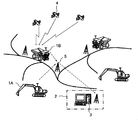
- FIG. 1 is a schematic diagram showing the configuration of an operation management system to which the present invention is applied.
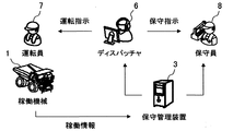
- FIG. 2 is a schematic diagram showing the flow of information together with the configuration of the operation management system to which the present invention is applied.
- operating machines (working machines) 1 such as excavators 1 ⁇ / b> A and dumpers 1 ⁇ / b> B are used in a quarry in a mine, and an operation management system that manages these operating machines 1 is used.
- a maintenance management device 3 is installed in a management office 2 near or in a quarry.
- the working machine 1 is provided with a position acquisition device (not shown) for acquiring the position of the own machine using the GPS satellite 4 and various sensors (not shown).
- the operation information (specifically, position, operation time, data of various sensors, etc.) and machine information (specifically, model, unit number, etc.) of each operating machine 1 are stored in a wireless communication system (specifically, for example,
- the data is transmitted to the maintenance management device 3 via a wireless communication device on the operating machine 1 side, a relay station 5, a wireless communication device on the management office 2 side, and the like.
- the maintenance management device 3 displays a management screen (not shown) indicating information collected from each operating machine 1, and the manager 6 (dispatcher) monitors this management screen.
- the administrator 6 judges from the information shown on the management screen and issues an operation instruction to the operator 7 of the working machine 1 and also issues a maintenance instruction to the maintenance person 8.
- the maintenance staff 8 performs maintenance work on the working machine 1 in accordance with the maintenance instruction.
- the maintenance staff 8 holds a portable terminal (not shown) that receives and displays information from the maintenance management apparatus 3, and performs maintenance work by judging from the information displayed on the portable terminal. Also good.
- the maintenance management device 3 diagnoses whether or not an abnormality has occurred in the data of various sensors collected from each operating machine 1, and displays state abnormality information (details will be described later) when it is determined that an abnormality has occurred. It is supposed to be. Furthermore, a grace period and maintenance cost are estimated and displayed corresponding to each state abnormality information. Specifically, for example, a first grace period until a failure occurs and a failure maintenance cost when a failure occurs after the first grace period elapses are displayed, and a combination thereof is displayed. In addition, a second grace period in which preventive maintenance can be postponed without causing a failure, and a preventive maintenance cost required when the second grace period elapses without causing a failure, and a combination thereof is displayed. .
- state abnormality information (details will be described later) when it is determined that an abnormality has occurred. It is supposed to be.
- a grace period and maintenance cost are estimated and displayed corresponding to each state abnormality information. Specifically, for example, a first grace period until
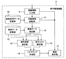
- FIG. 3 is a block diagram showing a functional configuration of the maintenance management device 3 in the present embodiment.
- the maintenance management device 3 includes an operation information input unit 9, a diagnostic reference data storage unit 10, a state abnormality diagnosis unit 11, a case data storage unit 12, a case data extraction unit 13, and a grace period estimation unit 14.
- the operation information input unit 9 inputs operation information collected from each operation machine 1 and associated with the body information (specifically, the position, operation time, sensor data, etc. of the operation machine 1). A part of the operation information associated with the machine body information is output and displayed on the screen display unit 17, and sensor data associated with the machine body information is output to the state abnormality diagnosis unit 11.
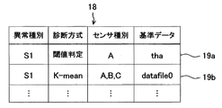
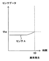
- the diagnostic standard data storage unit 10 stores diagnostic standard data 18 (see FIG. 4) in advance, and the state abnormality diagnostic unit 11 adds sensor data input from the operation information input unit 9 based on the diagnostic standard data 18. On the other hand, it is diagnosed whether or not an abnormality (a sign of failure) has occurred (in other words, whether or not a state abnormality that does not hinder the operation of the operating machine 1 has occurred).
- the diagnosis reference data 18 includes, as data items, an abnormality type, a diagnosis method, a sensor type, and reference data, and the diagnosis reference record in each row in FIG. 4 indicates one diagnosis process.
- One or more diagnostic reference records are prepared in advance for each type of abnormality, and it is selected and set in advance which diagnostic reference record is to be performed.
- diagnosis processing when the diagnosis process based on the diagnosis reference record 19a shown in FIG. 4 is performed (in other words, when the diagnosis is performed by the threshold determination method), the reference data tha is obtained by using the data of the sensor A input from the operation information input unit 9. Used as a threshold. And it is diagnosed whether abnormality S1 generate
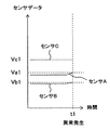
- the K-means method is a data classification method that classifies multivariate data without teaching. Each input data is regarded as a point in the multivariate space, and the proximity of each point to the Euclidean distance is used as a reference. Is a method of finding a cluster of data.
- the data of sensor A, the data of sensor B, and the data of sensor C are treated as multivariate data, and a cluster of data generated from time-series data at normal time is acquired in advance and stored in advance as detafile0. Yes.
- the sensor A data, the sensor B data, and the sensor C data input from the operation information input unit 9 are not included in the normal data cluster, or the spatial distance from the cluster is By determining whether or not it is large (in other words, by determining whether or not the data deviates from normal data), it is diagnosed whether or not an abnormality S1 has occurred. For example, as shown in FIG.
- the state abnormality diagnosis unit 11 diagnoses that an abnormality has occurred
- the state abnormality diagnosis unit 11 outputs state abnormality information (specifically, for example, the type of abnormality and the occurrence time of the abnormality) to the screen display unit 17 in association with the body information.
- the screen display unit 17 displays a state abnormality screen (not shown) indicating each state abnormality information.
- the sensor data in the abnormality type, the abnormality occurrence time, and the abnormality occurrence time is associated with the body information and is transmitted to the case data extraction unit 13. It is designed to output.
- the sensor at the abnormality type “S1”, the abnormality occurrence time “t1”, and the abnormality occurrence time t1 are output to the case data extraction unit 13 in association with the body information.
- the case data storage unit 12 constructs a case database 20 as shown in FIG. 7, for example, and includes a plurality of case data (specifically, failure case data relating to a case where a failure has occurred and failure maintenance has been performed, Preventive maintenance case data relating to a case where preventive maintenance is performed before the occurrence of the problem is stored in advance.
- the case database 20 includes a case management data table 21, a case sensor data table 22, a maintenance work data table 23, and a cost data table 24, which are associated with each other.
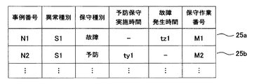
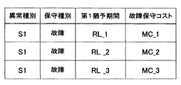
- the case management data table 21 has, as data items, a case number, an abnormality type, a maintenance type, a preventive maintenance execution time, a failure occurrence time, and a maintenance work number. Case management records in each row form part of each case data. Specifically, the case management record with the maintenance type “failure” and including the failure occurrence time constitutes a part of failure case data (in other words, failure maintenance case data), and the maintenance type is “prevention”. The case management record including the execution time of preventive maintenance constitutes a part of the preventive maintenance case data.
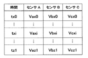
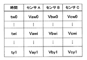
- the case sensor data table 22 stores case sensor data associated with each case management record (in other words, the case number of each case management record is given). Specifically, sensor data (see FIG. 9) before the failure occurrence time (for example, tz1) is stored for the case management record whose maintenance type is “failure” and includes the failure occurrence time. This constitutes part of the failure case data. For the case management record whose maintenance type is “preventive” and includes the preventive maintenance execution time, sensor data (see FIG. 10) before the preventive maintenance execution time (for example, ty1) is stored. This constitutes part of the preventive maintenance case data.
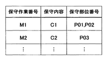
- the maintenance work data table 23 (see FIG. 11) has a maintenance work number, maintenance contents, and a maintenance part number as data items.
- the maintenance work numbers in the maintenance work data table 23 are associated with the maintenance work numbers in the case management data table 21, and the maintenance work records in each row in FIG. 11 constitute a part of each case data.
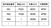
- the cost data table 24 (see FIG. 12) includes maintenance part numbers, parts costs, work costs, and work times as data items.
- the maintenance part number in the cost data table 24 is associated with the maintenance part number in the maintenance work data table 24.
- the maintenance work may involve part replacement or may not involve part replacement. Therefore, the cost record of each line in FIG. 12 includes a part cost and a work cost, and a part including a work cost without a part cost.
- the maintenance work record and the cost record associated with the case management record whose maintenance type is “failure” are information on the failure maintenance cost and constitute a part of the failure case data. Further, the maintenance work record and the cost record associated with the case management record whose maintenance type is “prevention” are information on the preventive maintenance cost and constitute a part of the preventive maintenance case data.
- the case data extraction unit 13 is configured to extract case data including the type of abnormality when it is diagnosed by the state abnormality diagnosis unit 11 that an abnormality has occurred. More specifically, the case management record including the same abnormality type is extracted from the case management data table 21 with reference to the abnormality type (for example, S1) input from the state abnormality diagnosis unit 11. Then, the extracted case management record is output to the grace period estimation unit 14 in association with the occurrence time of the abnormality input from the state abnormality diagnosis unit 11, the sensor data at the occurrence time of the abnormality, and the body information. Further, the extracted case management record is output to the maintenance cost estimation unit 15 in association with the abnormality occurrence time and machine information input from the state abnormality diagnosis unit 11.
- the abnormality type for example, S1
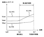
- the grace period estimation unit 14 calculates a grace period corresponding to each case management record input from the case data extraction unit 13. For example, when the maintenance type of the case management record input from the case data extraction unit 13 is “failure”, the first grace period until the failure occurs is calculated. Specifically, together with the case management record 25a shown in FIG. 8, the abnormality occurrence time “t1”, the sensor A data “Va1”, the sensor B data “Vb1”, and the sensor C data “ A case where “Vc1” is input from the case data extraction unit 13 will be described as an example.
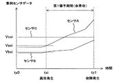
- the data of the sensor A, the data of the sensor B, and the data of the sensor C that are associated with the case management record 25a and before the failure occurrence time tz1 are searched (see FIG. 9). Then, with respect to the past sensor A data, sensor B data, and sensor C data searched, the sensor A data Va1, the sensor B data Vb1, and the sensor C data Vc1 at the current abnormality occurrence time t1. Is matched. More specifically, the spatial distance in the multivariate space is calculated in the same manner as the above-described K-means method, and sensor data (Vaxi, Vbxi, Vcxi) having a close spatial distance is searched. Thereby, as shown in FIG.
- the past abnormality occurrence time txi is acquired. Then, by calculating the difference between the past abnormality occurrence time txi and the corresponding past failure occurrence time tz1, the first grace period starting from the current abnormality occurrence time (in other words, the remaining lifetime) ) Is calculated. Then, the calculated first grace period is output to the risk map creation unit 16 in association with the corresponding case management record 25a (and the occurrence time of abnormality, machine information).
- the second grace period in which the preventive maintenance can be postponed without causing a failure is calculated.
- a case where “Vc1” is input will be described as an example.
- the past occurrence time twi of the abnormality is acquired.
- the second grace period starting from the current abnormality occurrence time is calculated by calculating the difference between the past abnormality occurrence time twi and the corresponding preventive maintenance execution time ty1 corresponding thereto.
- the calculated second grace period is output to the risk map creation unit 16 in association with the corresponding case management record 25b (and the occurrence time of the abnormality, the machine information).
- the maintenance cost estimation unit 15 calculates a maintenance cost corresponding to each case management record input from the case data extraction unit 13. That is, a failure management cost is calculated corresponding to a case management record whose maintenance type is “failure” (in other words, failure case data), and a case management record whose maintenance type is “prevention” (in other words, preventive maintenance case) Data) to calculate preventive maintenance costs. More specifically, first, referring to the maintenance work number (for example, “M1”) of the case management record, the maintenance work data table 23 is searched for a maintenance work record including the same maintenance work number.
- the cost data table 24 is searched for cost records including the same maintenance part number. Then, the parts cost (for example, “PC01” and “PC02”) and the work cost (for example, “WC01” and “WC01”) of the retrieved cost record are integrated to calculate the maintenance cost. Then, the calculated maintenance cost is output to the risk map creation unit 16 in association with the corresponding case management record (and the occurrence time of abnormality, machine information).
- the risk map creation unit 16 inputs the first grace period or the second grace period associated with the case management record (and the occurrence time of the abnormality, the aircraft information) from the grace period estimation unit 14, and the case management record (and The maintenance cost estimation unit 15 inputs a failure maintenance cost or a preventive maintenance cost associated with an abnormality occurrence time and machine information. Then, for example, as shown in FIG. 15, a combination of the first grace period and failure maintenance cost that share the case management record (and the occurrence time of the abnormality, the machine information) is created, and according to the abnormality type of the case management record Classify into groups. Further, for example, as shown in FIG.
- a combination of the second grace period and the preventive maintenance cost in which the case management record (and the occurrence time of the abnormality and the aircraft information) are common is created, and the combination of the case management record according to the abnormality type Classify into groups.
- a risk map 26 (see FIG. 17) is created for each type of abnormality, and the risk map 26 is output to the screen display unit 17 and displayed on the screen.
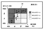
- the risk map 26 shows a combination of a grace period and a maintenance cost obtained based on each case data in a two-dimensional coordinate system with the grace period and the maintenance cost as coordinate axes.
- the combination of the first grace period obtained based on each failure case data and the failure maintenance cost (see the x in FIG. 17), and the second grace period obtained based on each preventive maintenance case data.
- the preventive maintenance cost combination (see ⁇ in FIG. 17) are plotted so as to be identifiable in the same coordinate system.
- the grace period is divided into a plurality of levels (ranges)
- the maintenance cost is divided into a plurality of levels (ranges)
- the entire coordinate system is divided into a plurality of risk zones (regions).
- the risk zone is shown to be identifiable by color tone.
- the grace period (RL) is divided into a small level (RL ⁇ ), a medium level ( ⁇ ⁇ RL ⁇ ), and a large level ( ⁇ ⁇ RL).
- the maintenance cost (MC) is divided into a small level (MC ⁇ ), a medium level ( ⁇ ⁇ MC ⁇ ), and a large level ( ⁇ ⁇ MC).
- the entire coordinate system is divided into a large risk zone (region satisfying the condition of RL ⁇ or ⁇ ⁇ MC), a medium risk zone ( ⁇ ⁇ RL ⁇ and MC ⁇ , or ⁇ ⁇ RL and ⁇ ⁇ MC ⁇ ). ) And small risk zones (regions satisfying ⁇ ⁇ RL and MC ⁇ ).
- the maintenance management device 3 diagnoses whether or not an abnormality has occurred in the sensor data collected from each operating machine 1, and when diagnosing that an abnormality has occurred, state abnormality information (specifically, for example, the type of abnormality) And an abnormal occurrence time) are displayed in association with the aircraft information. Thereby, the administrator can know the state abnormality of the working machine 1.
- the maintenance management device 3 extracts failure case data or preventive maintenance case data including the same abnormality type. For example, when failure case data is extracted, based on the failure case data, a first grace period until a failure occurs and a failure maintenance cost when a failure occurs after the first grace period elapses are estimated. . For example, when preventive maintenance case data is extracted, based on the preventive maintenance case data, a second grace period in which preventive maintenance can be postponed without causing a failure, and a second grace period without failure occurs. Estimate the preventive maintenance cost in the event of a failure. Then, a risk map indicating a combination of the first grace period and the failure maintenance cost or / and a combination of the second grace period and the preventive maintenance cost is created. Then, when the administrator operates the operation unit such as a keyboard or a mouse to select the state abnormality information (and the aircraft information) on the state abnormality screen and is instructed to display the risk map, the corresponding risk map is displayed. Display the risk map screen shown.
- the administrator can determine the maintenance timing from the time grace until the failure occurs based on the past results. it can. Further, the maintenance timing can be determined in consideration of not only the time delay until the failure occurs but also the failure maintenance cost. That is, for example, if the failure maintenance cost is high, it is possible to determine that it is better to perform preventive maintenance early so that a failure does not occur. In addition, for example, if the failure maintenance cost seems to be low, it is possible to determine that the preventive maintenance may be delayed in order to prevent the machine from being stopped for the preventive maintenance and the production efficiency from decreasing. .
- the administrator can suspend the preventive maintenance based on the past performance (in other words, no failure occurs).
- the maintenance timing can be determined from the time delay. Further, the maintenance timing can be determined in consideration of the preventive maintenance cost as well as the time delay in which the preventive maintenance can be postponed. That is, for example, if the preventive maintenance timing is delayed and the preventive maintenance cost increases, it can be determined that the preventive maintenance should be performed at an early stage.
- the risk map screen shown in FIG. 17 will be described.
- combinations of three first grace periods and failure maintenance costs (RL_1, MC_1), (RL_2, MC_2), and (RL_3, MC_3) are shown to belong to the large risk zone.
- the first grace period is at a medium level ( ⁇ ⁇ RL_1 ⁇ )
- the failure maintenance cost is at a high level ( ⁇ ⁇ MC_1).
- the first grace period is at a high level ( ⁇ ⁇ RL_2, ⁇ ⁇ RL_3), and the failure maintenance cost is at a high level ( ⁇ ⁇ MC_2, ⁇ ⁇ MC_3).
- the combination of two second grace periods and preventive maintenance costs (RL_4, MC_4), (RL_5, MC_5) is shown to belong to the medium risk zone, and they have the second grace period in the middle level. ( ⁇ ⁇ RL_4 ⁇ , ⁇ ⁇ RL_5 ⁇ ), and the preventive maintenance cost is at a medium level ( ⁇ ⁇ MC_4 ⁇ , ⁇ ⁇ MC_5 ⁇ ).
- combinations of four second grace periods and preventive maintenance costs (RL_6, MC_6), (RL_7, MC_7), (RL_8, MC_8), and (RL_9, MC_9) are shown to belong to the large risk zone. .
- the second grace period is at a low level (RL_6 ⁇ )
- the preventive maintenance cost is at a low level (MC_6 ⁇ )
- the second grace period is at a low level (RL_7 ⁇ )
- the preventive maintenance cost is at a medium level ( ⁇ ⁇ MC_7 ⁇ ).
- the second grace period is at a medium level ( ⁇ ⁇ RL_8 ⁇ ), and the preventive maintenance cost is at a high level ( ⁇ ⁇ MC_8).
- the second grace period is at a high level ( ⁇ ⁇ RL_9), and the preventive maintenance cost is at a high level ( ⁇ ⁇ MC_9).
- the administrator pays attention to the combination of the grace period and the maintenance cost (RL_1, MC_1), (RL_4, MC_4), (RL_5, MC_5), (RL_8, MC_8), and sets the maintenance timing to the grace period RL_4. , RL_5, or RL_8, or a timing before or before can be determined. Further, for example, paying attention to the combination of the grace period and the maintenance cost (RL_6, MC_6), (RL_7, MC_7), (RL_8, MC_8), the delay of the preventive maintenance timing increases the preventive maintenance cost. It is possible to judge that it is better to carry out at an early stage.
- support for determining the maintenance timing of the working machine 1 can be performed. Therefore, the burden on the administrator can be reduced.
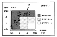
- the grace period estimation unit 14 calculates a grace period starting from the current occurrence time of the abnormality, and the risk map creation unit 16 uses the grace period starting from the current occurrence time of the abnormality.
- the case where the risk map 26 indicating the combination of the period and the maintenance cost is created and displayed on the screen display unit 17 has been described as an example.
- the present invention is not limited to this, and various modifications can be made without departing from the scope of the invention and the technical idea. Can be modified. That is, for example, the grace period estimation unit 14 presents when the time has elapsed from the occurrence of the current abnormality until the present time (specifically, the current date and time or the current operation time input from the operation information input unit 9).
- the grace period starting from the current time may be calculated by calculating the difference between the occurrence time of the current abnormality and the current time, and subtracting the difference from the grace period starting from the current time of occurrence of the abnormality.
- the risk map creation unit 16 may create a risk map 26 indicating a combination of a grace period and a maintenance cost starting from the current time and display the risk map 26 on the screen display unit 17. That is, the risk map 26 transitions from the state shown in FIG. 17 to the state shown in FIG. 18 with time (that is, the display data moves to the left).
- the administrator must judge that the timing for performing preventive maintenance is approaching because the number of cases belonging to the medium risk zone has decreased and the number of cases belonging to the large risk zone has increased. Is possible.
- the risk map creation unit 16 creates a risk map 26 that plots a combination of a grace period and a maintenance cost in a two-dimensional coordinate system, and displays this on the screen.
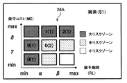
- the risk map creation unit 16 uses the first region (RL ⁇ and MC ⁇ ) and the second region (RL ⁇ and ⁇ ⁇ MC ⁇ ).
- a risk map 26A indicating the number of combinations of grace periods and maintenance costs classified into regions ( ⁇ ⁇ RL and ⁇ ⁇ MC) may be created and displayed on the screen display unit 17. Good.
- FIG. 1 Third region (RL ⁇ and ⁇ ⁇ MC), fourth region ( ⁇ ⁇ RL ⁇ and MC ⁇ ), fifth region ( ⁇ ⁇ RL ⁇ and ⁇ ⁇ MC ⁇ ), 6 region ( ⁇ ⁇ RL ⁇ and ⁇ ⁇ MC), 7th region ( ⁇ ⁇ RL and MC ⁇ ) region, 8th region ( ⁇ ⁇ RL and ⁇ ⁇ MC ⁇ ), and 9th region
- a risk map 26A indicating the number of combinations of grace periods and maintenance costs classified into regions ( ⁇ ⁇ RL and ⁇ ⁇ MC) may be created and displayed on the screen display unit 17. Good.
- FIG. 1 Third region (RL ⁇ and ⁇ ⁇ MC), fourth region ( ⁇ ⁇ RL ⁇ and MC ⁇ ), fifth region ( ⁇ ⁇ RL ⁇
- the number of combinations of the first grace period and the failure maintenance cost is shown outside the parentheses, and the number of combinations of the second grace period and the preventive maintenance cost is shown in parentheses.
- the first to third, sixth, and ninth areas correspond to the large risk zone
- the fourth, fifth, and eighth areas correspond to the medium risk zone
- the seventh area corresponds to the small risk zone.
- each region is shown to be identifiable by color tone or the like according to the risk zone, as in the above embodiment. Also in such a modification, the same effect as the one embodiment can be obtained.
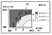
- the risk map 26 has been described as an example in which the risk map 26 is divided into a large risk zone, a medium risk zone, and a small risk zone using a polygonal boundary as shown in FIG.
- an arc-shaped boundary line may be used to divide into a large risk zone, a medium risk zone, and a small risk zone.
- the radius of the axis of the first arc specifically, the maximum value MAX of the grace period and the minimum value MIN of the maintenance cost are centered).
- a small area with a large maintenance cost may be set as a large risk zone, and an area between the first arc and the second arc may be divided into medium risk zones. Also in such a modification, the same effect as the one embodiment can be obtained.
- the maintenance management device 3 may include a periodic maintenance information storage unit 27 as shown in FIG.
- This periodic maintenance information storage unit 27 is set as the manufacturer's recommended value as the periodic maintenance information or is set in advance by the operator as a periodic maintenance interval, and the previous periodic maintenance execution time in each operating machine 1. I remember. Therefore, it is possible to calculate the next periodic maintenance timing based on the periodic maintenance information. Therefore, as a modification, the risk map creation unit 16 changes the setting of ⁇ so as to correspond to the next periodic maintenance timing, and changes the setting of ⁇ so as to correspond to the next periodic maintenance timing.
- 26 (or 26A, 26B) may be created and displayed on the screen display unit 17.
- the timing of the regular maintenance may be indicated on the risk map 26 (or 26A, 26B) by changing the risk zone so as to match the timing of the regular maintenance.
- the administrator can determine the timing of preventive maintenance while referring to the timing of periodic maintenance. Specifically, for example, according to the risk map screen shown in FIG. 17, when preventive maintenance is performed in accordance with the timing ( ⁇ ) of the next periodic maintenance, the occurrence of a failure can be prevented with a high probability.
- preventive maintenance is performed in accordance with the periodic maintenance timing ( ⁇ )
- preventive maintenance costs are higher than when preventive maintenance is performed at the next periodic maintenance timing ( ⁇ ). Judgment can be made.
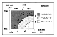
- the screen display unit 17 may display timing lines PM1 and PM2 indicating the regular maintenance timing on the risk map 26B as shown in FIG.
- the administrator can determine the timing of preventive maintenance while referring to the timing of periodic maintenance. Specifically, when preventive maintenance is performed in accordance with the next periodic maintenance timing (PM1), the occurrence of a failure can be prevented with a high probability, and preventive maintenance is performed in accordance with the next periodic maintenance timing (PM2). It is possible to determine that a failure may occur before the preventive maintenance is performed. In addition, when preventive maintenance is performed at the next periodic maintenance timing (PM2), preventive maintenance costs are higher than when preventive maintenance is performed at the next periodic maintenance timing (PM1). Judgment can be made.
- the administrator may operate the operation unit such as a keyboard or a mouse so that the timing line on the risk map 26B can be moved in the axial direction of the grace period (see FIG. 23). Then, the periodic maintenance interval may be calculated in response to the change of the timing line, and the calculated periodic maintenance interval may be output to the periodic maintenance information storage unit 27 for rewriting. That is, it is possible to change the setting and timing of periodic maintenance using the risk map screen.
- the combination of the first grace period and the failure maintenance cost and the combination of the second grace period and the preventive maintenance cost are shown in the same risk map 26 (or 26A, 26B).
- different risk maps in other words, different coordinate systems
- the same effect as described above can be obtained.
- case data storage unit 12 has been described by taking as an example a case in which failure case data and preventive maintenance case data are stored in advance.
- the present invention is not limited to this, and the gist and technology of the present invention Various modifications can be made without departing from the scope of the idea.
- the case data storage unit 12 may store only failure case data in advance.
- the case data extraction unit 13 extracts failure case data including the type of abnormality.
- the grace period estimation unit 14 calculates a first grace period based on each extracted failure case data
- the maintenance cost estimation unit 15 calculates a failure maintenance cost based on each extracted failure case data.
- the risk map creation unit 16 creates a risk map indicating a combination of the first grace period and the failure maintenance cost obtained based on each failure case data, and displays the risk map on the screen display unit 17. In this case, the same effect as described above can be obtained.
- the case data storage unit 12 may store only preventive maintenance case data in advance.
- the case data extraction unit 13 extracts the preventive maintenance case data including the type of abnormality when the state abnormality diagnosis unit 11 diagnoses that an abnormality has occurred.
- the grace period estimation unit 14 calculates the second grace period based on each preventive maintenance case data
- the maintenance cost estimation unit 15 calculates the preventive maintenance cost based on each extracted preventive maintenance case data, and the maintenance cost.
- the estimation unit 15 calculates the preventive maintenance cost based on each extracted preventive maintenance case data.
- the risk map creation unit 16 creates a risk map indicating a combination of the second grace period and the preventive maintenance cost obtained based on each preventive maintenance case data, and causes the screen display unit 17 to display the risk map. In this case, the same effect as described above can be obtained.
- the case where the risk map creation unit 16 is provided and the risk map 26 (or 26A, 26B) created by the risk map 16 is displayed has been described as an example.
- the present invention is not limited, and various modifications can be made without departing from the spirit and technical scope of the present invention. That is, for example, instead of the risk map creation unit 16, a list as shown in FIG. 15 or FIG. 16 described above (preferably, information indicating which risk zone the combination of the grace period and the maintenance cost belongs to is added.
- a list creation unit (not shown) to be created, and the list created by the list creation unit may be displayed on the screen display unit 17. Even in such a modification, it is possible to assist in determining the maintenance timing of the operating machine 1.
- the case data stored in advance in the case data storage unit 12 is the case sensor data (specifically, sensor data before the occurrence of a past failure or past preventive maintenance is performed).
- the grace period estimation unit 14 includes a case where the occurrence time of the past abnormality is calculated by collating the sensor data at the occurrence time of the current abnormality with the case sensor data.
- the present invention is not limited to this, and various modifications can be made without departing from the spirit and technical scope of the present invention. That is, for example, the case data may include an abnormality occurrence time instead of the case sensor data. Even in such a modification, the same effect as described above can be obtained.
- the case data stored in advance in the case data storage 12 includes a maintenance work record and a cost record as information on the maintenance cost.
- the maintenance cost estimation unit includes the maintenance work record and the maintenance work record.
Landscapes
- Business, Economics & Management (AREA)
- Engineering & Computer Science (AREA)
- Physics & Mathematics (AREA)
- General Physics & Mathematics (AREA)
- Strategic Management (AREA)
- Development Economics (AREA)
- Human Resources & Organizations (AREA)
- Theoretical Computer Science (AREA)
- General Business, Economics & Management (AREA)
- Marketing (AREA)
- Economics (AREA)
- Tourism & Hospitality (AREA)
- Entrepreneurship & Innovation (AREA)
- Accounting & Taxation (AREA)
- Finance (AREA)
- Structural Engineering (AREA)
- Civil Engineering (AREA)
- Mining & Mineral Resources (AREA)
- General Engineering & Computer Science (AREA)
- Quality & Reliability (AREA)
- Operations Research (AREA)
- Game Theory and Decision Science (AREA)
- Primary Health Care (AREA)
- General Health & Medical Sciences (AREA)
- Health & Medical Sciences (AREA)
- Automation & Control Theory (AREA)
- Testing And Monitoring For Control Systems (AREA)
- Component Parts Of Construction Machinery (AREA)
- Management, Administration, Business Operations System, And Electronic Commerce (AREA)
- Operation Control Of Excavators (AREA)
Priority Applications (1)
| Application Number | Priority Date | Filing Date | Title |
|---|---|---|---|
| US14/414,282 US10235658B2 (en) | 2012-07-13 | 2013-07-10 | Maintenance management device for operating machinery |
Applications Claiming Priority (2)
| Application Number | Priority Date | Filing Date | Title |
|---|---|---|---|
| JP2012158052A JP5988740B2 (ja) | 2012-07-13 | 2012-07-13 | 稼働機械の保守管理装置 |
| JP2012-158052 | 2012-07-13 |
Publications (1)
| Publication Number | Publication Date |
|---|---|
| WO2014010632A1 true WO2014010632A1 (ja) | 2014-01-16 |
Family
ID=49916082
Family Applications (1)
| Application Number | Title | Priority Date | Filing Date |
|---|---|---|---|
| PCT/JP2013/068888 Ceased WO2014010632A1 (ja) | 2012-07-13 | 2013-07-10 | 稼働機械の保守管理装置 |
Country Status (3)
| Country | Link |
|---|---|
| US (1) | US10235658B2 (enExample) |
| JP (1) | JP5988740B2 (enExample) |
| WO (1) | WO2014010632A1 (enExample) |
Cited By (2)
| Publication number | Priority date | Publication date | Assignee | Title |
|---|---|---|---|---|
| WO2018042940A1 (ja) * | 2016-09-01 | 2018-03-08 | 富士電機株式会社 | 設備管理装置、設備管理システム、プログラムおよび設備管理方法 |
| JP2018185774A (ja) * | 2017-04-27 | 2018-11-22 | 富士電機株式会社 | 設備管理装置、設備管理システム、プログラムおよび設備管理方法 |
Families Citing this family (20)
| Publication number | Priority date | Publication date | Assignee | Title |
|---|---|---|---|---|
| EP3155490B1 (de) * | 2014-07-25 | 2019-04-03 | Siemens Aktiengesellschaft | Verfahren, anordnung, und computerprogrammprodukt für eine zustandsbasierte berechnung eines wartungstermins einer technischen anlage |
| JP6508963B2 (ja) * | 2015-02-16 | 2019-05-08 | 住友重機械工業株式会社 | ショベル支援装置 |
| WO2017037905A1 (ja) * | 2015-09-02 | 2017-03-09 | サン電子株式会社 | サーバ及びコンピュータプログラム |
| JP5992087B1 (ja) | 2015-12-28 | 2016-09-14 | ファナック株式会社 | 機械の保全計画を作成する予防保全管理システム |
| US9805524B2 (en) * | 2016-03-11 | 2017-10-31 | General Electric Company | Systems and methods for displaying a fault analysis instructions of an engine control subsystem |
| KR101759916B1 (ko) * | 2016-05-20 | 2017-07-20 | 주식회사 세이프티아 | 공정 및 작업 위험도에 의한 위험지도 기반의 안전관리를 위한 서버, 시스템 및 방법 |
| US20210278832A1 (en) * | 2016-06-30 | 2021-09-09 | Nec Corporation | Maintenance plan formulation device, method, and non-transitory medium |
| JP6302014B2 (ja) * | 2016-08-16 | 2018-03-28 | ファナック株式会社 | セル制御装置 |
| JP6860406B2 (ja) * | 2017-04-05 | 2021-04-14 | 株式会社荏原製作所 | 半導体製造装置、半導体製造装置の故障予知方法、および半導体製造装置の故障予知プログラム |
| EP3404502B1 (en) * | 2017-05-17 | 2021-03-03 | Caverion Oyj | Condition-based maintenance of device |
| WO2019089380A1 (en) * | 2017-10-31 | 2019-05-09 | Nordson Corporation | Systems and methods for adaptive preventative maintenance in liquid dispensing systems and related equipment |
| JP7281875B2 (ja) * | 2018-06-27 | 2023-05-26 | 株式会社小松製作所 | メンテナンス支援装置、作業機械、メンテナンス支援システム及びメンテナンス支援方法 |
| JP7461879B2 (ja) * | 2018-07-10 | 2024-04-04 | 住友重機械工業株式会社 | 建設機械の表示方法及び建設機械の支援装置 |
| WO2020026437A1 (ja) * | 2018-08-03 | 2020-02-06 | 本田技研工業株式会社 | 情報管理装置、車両および方法 |
| JP6736733B1 (ja) | 2019-07-22 | 2020-08-05 | 日東電工株式会社 | 設備異常処置タイミング決定システム、設備異常処置タイミング決定方法及びコンピュータ・プログラム |
| US20220039339A1 (en) * | 2020-08-04 | 2022-02-10 | Lindsay Corporation | Maintenance monitoring and reporting system for a mobile agricultural irrigation system |
| US11961052B2 (en) * | 2020-12-15 | 2024-04-16 | Caterpillar Inc. | Systems and methods for wear assessment and part replacement timing optimization |
| JP7461899B2 (ja) * | 2021-01-08 | 2024-04-04 | 日立建機株式会社 | 保守支援システム |
| DE112023005525T5 (de) * | 2023-03-06 | 2025-10-30 | Komatsu Ltd. | Motordiagnosesystem und motordiagnoseverfahren |
| JP7738805B1 (ja) * | 2023-12-18 | 2025-09-12 | 三菱電機株式会社 | 更新計画装置、更新計画方法及び更新計画プログラム |
Citations (6)
| Publication number | Priority date | Publication date | Assignee | Title |
|---|---|---|---|---|
| JPH0954613A (ja) * | 1995-08-11 | 1997-02-25 | Toshiba Corp | プラント設備監視装置 |
| JP2002073155A (ja) * | 2000-08-31 | 2002-03-12 | Toshiba Corp | プラント機器の運用診断装置及びその運用診断方法 |
| JP2002195056A (ja) * | 2000-12-22 | 2002-07-10 | Central Res Inst Of Electric Power Ind | ガスタービン高温部品の廃却損最小化方法及びシステム及びガスタービン保守最適化支援プログラムを記録したコンピュータ読取可能な記録媒体 |
| JP2004145496A (ja) * | 2002-10-23 | 2004-05-20 | Hitachi Ltd | 機器設備の保守支援方法 |
| JP2007257376A (ja) * | 2006-03-23 | 2007-10-04 | Mitsubishi Heavy Ind Ltd | プラント用運転管理支援システム |
| JP2012094044A (ja) * | 2010-10-28 | 2012-05-17 | Hitachi Ltd | 異常診断装置および産業機械 |
Family Cites Families (4)
| Publication number | Priority date | Publication date | Assignee | Title |
|---|---|---|---|---|
| JP2001344404A (ja) * | 2000-03-31 | 2001-12-14 | Toshiba Corp | 製品ライフサイクル計画支援プログラム |
| US6832205B1 (en) * | 2000-06-30 | 2004-12-14 | General Electric Company | System and method for automatically predicting the timing and costs of service events in a life cycle of a product |
| US7088255B2 (en) * | 2001-05-29 | 2006-08-08 | Westinghouse Electric Co, Llc | Health monitoring display system for a complex plant |
| EP2186950B1 (en) | 2007-08-09 | 2016-10-12 | Hitachi Construction Machinery Co., Ltd | Instrument diagnostic system for a working machine |
-
2012
- 2012-07-13 JP JP2012158052A patent/JP5988740B2/ja active Active
-
2013
- 2013-07-10 WO PCT/JP2013/068888 patent/WO2014010632A1/ja not_active Ceased
- 2013-07-10 US US14/414,282 patent/US10235658B2/en active Active
Patent Citations (6)
| Publication number | Priority date | Publication date | Assignee | Title |
|---|---|---|---|---|
| JPH0954613A (ja) * | 1995-08-11 | 1997-02-25 | Toshiba Corp | プラント設備監視装置 |
| JP2002073155A (ja) * | 2000-08-31 | 2002-03-12 | Toshiba Corp | プラント機器の運用診断装置及びその運用診断方法 |
| JP2002195056A (ja) * | 2000-12-22 | 2002-07-10 | Central Res Inst Of Electric Power Ind | ガスタービン高温部品の廃却損最小化方法及びシステム及びガスタービン保守最適化支援プログラムを記録したコンピュータ読取可能な記録媒体 |
| JP2004145496A (ja) * | 2002-10-23 | 2004-05-20 | Hitachi Ltd | 機器設備の保守支援方法 |
| JP2007257376A (ja) * | 2006-03-23 | 2007-10-04 | Mitsubishi Heavy Ind Ltd | プラント用運転管理支援システム |
| JP2012094044A (ja) * | 2010-10-28 | 2012-05-17 | Hitachi Ltd | 異常診断装置および産業機械 |
Cited By (2)
| Publication number | Priority date | Publication date | Assignee | Title |
|---|---|---|---|---|
| WO2018042940A1 (ja) * | 2016-09-01 | 2018-03-08 | 富士電機株式会社 | 設備管理装置、設備管理システム、プログラムおよび設備管理方法 |
| JP2018185774A (ja) * | 2017-04-27 | 2018-11-22 | 富士電機株式会社 | 設備管理装置、設備管理システム、プログラムおよび設備管理方法 |
Also Published As
| Publication number | Publication date |
|---|---|
| JP2014021627A (ja) | 2014-02-03 |
| US10235658B2 (en) | 2019-03-19 |
| JP5988740B2 (ja) | 2016-09-07 |
| US20150206104A1 (en) | 2015-07-23 |
Similar Documents
| Publication | Publication Date | Title |
|---|---|---|
| JP5988740B2 (ja) | 稼働機械の保守管理装置 | |
| JP6060261B2 (ja) | 状態監視装置 | |
| JP6411769B2 (ja) | 状態監視装置 | |
| JP5858839B2 (ja) | 作業機械の異常診断装置 | |
| US10860004B2 (en) | Management system and non-transitory computer-readable recording medium | |
| JP6039696B2 (ja) | ショベルの異常判定方法、管理装置、及びショベル | |
| US10747212B2 (en) | Management system and non-transitory computer-readable recording medium | |
| KR20180082606A (ko) | 예측 모델에 기반하여 데이터 취득 파라미터들을 변경하기 위한 컴퓨터 구조 및 방법 | |
| US20190188110A1 (en) | Industrial control system, and assistance apparatus, control assist method, and program thereof | |
| US20250191083A1 (en) | Mine management system | |
| US12339641B2 (en) | Distributed system and data transmission method | |
| US20140188777A1 (en) | Methods and systems for identifying a precursor to a failure of a component in a physical system | |
| JP5809105B2 (ja) | メンテナンス手法選択装置、メンテナンス手法選択方法およびプログラム | |
| US9327846B2 (en) | Fleet performance optimization tool enhancement | |
| JP5918661B2 (ja) | 設備診断装置および設定変更督促方法 | |
| US20160210580A1 (en) | Method of determining availability and reliability of facility equipment | |
| JP7000266B2 (ja) | 分析フロー作成システムおよび分析フロー作成方法 | |
| WO2013143846A1 (en) | Monitoring the progress of a scheduled activity in an industrial process | |
| JP2021114255A (ja) | 予測装置、予測方法およびプログラム | |
| JP6441433B1 (ja) | 予兆診断装置 | |
| US20220270035A1 (en) | Global monitoring system for critical equipment performance evaluation | |
| CA2869468A1 (en) | Evaluating consequences of a fault in an industrial process | |
| JP2018124804A (ja) | 機器状態表示装置 | |
| KR20190011766A (ko) | 스마트한 제조 어셈블리 라인 성능을 위한 시각적 진단/분석 시스템 및 방법 |
Legal Events
| Date | Code | Title | Description |
|---|---|---|---|
| 121 | Ep: the epo has been informed by wipo that ep was designated in this application |
Ref document number: 13817017 Country of ref document: EP Kind code of ref document: A1 |
|
| WWE | Wipo information: entry into national phase |
Ref document number: 14414282 Country of ref document: US |
|
| NENP | Non-entry into the national phase |
Ref country code: DE |
|
| 122 | Ep: pct application non-entry in european phase |
Ref document number: 13817017 Country of ref document: EP Kind code of ref document: A1 |