WO2014007278A1 - 鉄基焼結合金製バルブシート - Google Patents
鉄基焼結合金製バルブシート Download PDFInfo
- Publication number
- WO2014007278A1 WO2014007278A1 PCT/JP2013/068228 JP2013068228W WO2014007278A1 WO 2014007278 A1 WO2014007278 A1 WO 2014007278A1 JP 2013068228 W JP2013068228 W JP 2013068228W WO 2014007278 A1 WO2014007278 A1 WO 2014007278A1
- Authority
- WO
- WIPO (PCT)
- Prior art keywords
- valve seat
- iron
- alloy
- mass
- based sintered
- Prior art date
- Legal status (The legal status is an assumption and is not a legal conclusion. Google has not performed a legal analysis and makes no representation as to the accuracy of the status listed.)
- Ceased
Links
Images
Classifications
-
- F—MECHANICAL ENGINEERING; LIGHTING; HEATING; WEAPONS; BLASTING
- F01—MACHINES OR ENGINES IN GENERAL; ENGINE PLANTS IN GENERAL; STEAM ENGINES
- F01L—CYCLICALLY OPERATING VALVES FOR MACHINES OR ENGINES
- F01L3/00—Lift-valve, i.e. cut-off apparatus with closure members having at least a component of their opening and closing motion perpendicular to the closing faces; Parts or accessories thereof
- F01L3/02—Selecting particular materials for valve-members or valve-seats; Valve-members or valve-seats composed of two or more materials
-
- C—CHEMISTRY; METALLURGY
- C21—METALLURGY OF IRON
- C21D—MODIFYING THE PHYSICAL STRUCTURE OF FERROUS METALS; GENERAL DEVICES FOR HEAT TREATMENT OF FERROUS OR NON-FERROUS METALS OR ALLOYS; MAKING METAL MALLEABLE, e.g. BY DECARBURISATION OR TEMPERING
- C21D6/00—Heat treatment of ferrous alloys
- C21D6/002—Heat treatment of ferrous alloys containing Cr
-
- C—CHEMISTRY; METALLURGY
- C22—METALLURGY; FERROUS OR NON-FERROUS ALLOYS; TREATMENT OF ALLOYS OR NON-FERROUS METALS
- C22C—ALLOYS
- C22C33/00—Making ferrous alloys
- C22C33/02—Making ferrous alloys by powder metallurgy
-
- C—CHEMISTRY; METALLURGY
- C22—METALLURGY; FERROUS OR NON-FERROUS ALLOYS; TREATMENT OF ALLOYS OR NON-FERROUS METALS
- C22C—ALLOYS
- C22C33/00—Making ferrous alloys
- C22C33/02—Making ferrous alloys by powder metallurgy
- C22C33/0257—Making ferrous alloys by powder metallurgy characterised by the range of the alloying elements
- C22C33/0278—Making ferrous alloys by powder metallurgy characterised by the range of the alloying elements with at least one alloying element having a minimum content above 5%
- C22C33/0285—Making ferrous alloys by powder metallurgy characterised by the range of the alloying elements with at least one alloying element having a minimum content above 5% with Cr, Co, or Ni having a minimum content higher than 5%
-
- C—CHEMISTRY; METALLURGY
- C22—METALLURGY; FERROUS OR NON-FERROUS ALLOYS; TREATMENT OF ALLOYS OR NON-FERROUS METALS
- C22C—ALLOYS
- C22C38/00—Ferrous alloys, e.g. steel alloys
-
- C—CHEMISTRY; METALLURGY
- C22—METALLURGY; FERROUS OR NON-FERROUS ALLOYS; TREATMENT OF ALLOYS OR NON-FERROUS METALS
- C22C—ALLOYS
- C22C38/00—Ferrous alloys, e.g. steel alloys
- C22C38/002—Ferrous alloys, e.g. steel alloys containing In, Mg, or other elements not provided for in one single group C22C38/001 - C22C38/60
-
- C—CHEMISTRY; METALLURGY
- C22—METALLURGY; FERROUS OR NON-FERROUS ALLOYS; TREATMENT OF ALLOYS OR NON-FERROUS METALS
- C22C—ALLOYS
- C22C38/00—Ferrous alloys, e.g. steel alloys
- C22C38/02—Ferrous alloys, e.g. steel alloys containing silicon
-
- C—CHEMISTRY; METALLURGY
- C22—METALLURGY; FERROUS OR NON-FERROUS ALLOYS; TREATMENT OF ALLOYS OR NON-FERROUS METALS
- C22C—ALLOYS
- C22C38/00—Ferrous alloys, e.g. steel alloys
- C22C38/18—Ferrous alloys, e.g. steel alloys containing chromium
- C22C38/22—Ferrous alloys, e.g. steel alloys containing chromium with molybdenum or tungsten
-
- C—CHEMISTRY; METALLURGY
- C22—METALLURGY; FERROUS OR NON-FERROUS ALLOYS; TREATMENT OF ALLOYS OR NON-FERROUS METALS
- C22C—ALLOYS
- C22C38/00—Ferrous alloys, e.g. steel alloys
- C22C38/18—Ferrous alloys, e.g. steel alloys containing chromium
- C22C38/24—Ferrous alloys, e.g. steel alloys containing chromium with vanadium
-
- C—CHEMISTRY; METALLURGY
- C22—METALLURGY; FERROUS OR NON-FERROUS ALLOYS; TREATMENT OF ALLOYS OR NON-FERROUS METALS
- C22C—ALLOYS
- C22C38/00—Ferrous alloys, e.g. steel alloys
- C22C38/18—Ferrous alloys, e.g. steel alloys containing chromium
- C22C38/30—Ferrous alloys, e.g. steel alloys containing chromium with cobalt
-
- C—CHEMISTRY; METALLURGY
- C22—METALLURGY; FERROUS OR NON-FERROUS ALLOYS; TREATMENT OF ALLOYS OR NON-FERROUS METALS
- C22C—ALLOYS
- C22C38/00—Ferrous alloys, e.g. steel alloys
- C22C38/18—Ferrous alloys, e.g. steel alloys containing chromium
- C22C38/36—Ferrous alloys, e.g. steel alloys containing chromium with more than 1.7% by weight of carbon
-
- F—MECHANICAL ENGINEERING; LIGHTING; HEATING; WEAPONS; BLASTING
- F01—MACHINES OR ENGINES IN GENERAL; ENGINE PLANTS IN GENERAL; STEAM ENGINES
- F01L—CYCLICALLY OPERATING VALVES FOR MACHINES OR ENGINES
- F01L3/00—Lift-valve, i.e. cut-off apparatus with closure members having at least a component of their opening and closing motion perpendicular to the closing faces; Parts or accessories thereof
- F01L3/22—Valve-seats not provided for in preceding subgroups of this group; Fixing of valve-seats
-
- F—MECHANICAL ENGINEERING; LIGHTING; HEATING; WEAPONS; BLASTING
- F16—ENGINEERING ELEMENTS AND UNITS; GENERAL MEASURES FOR PRODUCING AND MAINTAINING EFFECTIVE FUNCTIONING OF MACHINES OR INSTALLATIONS; THERMAL INSULATION IN GENERAL
- F16K—VALVES; TAPS; COCKS; ACTUATING-FLOATS; DEVICES FOR VENTING OR AERATING
- F16K25/00—Details relating to contact between valve members and seats
- F16K25/005—Particular materials for seats or closure elements
-
- B—PERFORMING OPERATIONS; TRANSPORTING
- B22—CASTING; POWDER METALLURGY
- B22F—WORKING METALLIC POWDER; MANUFACTURE OF ARTICLES FROM METALLIC POWDER; MAKING METALLIC POWDER; APPARATUS OR DEVICES SPECIALLY ADAPTED FOR METALLIC POWDER
- B22F5/00—Manufacture of workpieces or articles from metallic powder characterised by the special shape of the product
- B22F5/10—Manufacture of workpieces or articles from metallic powder characterised by the special shape of the product of articles with cavities or holes, not otherwise provided for in the preceding subgroups
- B22F5/106—Tube or ring forms
-
- C—CHEMISTRY; METALLURGY
- C21—METALLURGY OF IRON
- C21D—MODIFYING THE PHYSICAL STRUCTURE OF FERROUS METALS; GENERAL DEVICES FOR HEAT TREATMENT OF FERROUS OR NON-FERROUS METALS OR ALLOYS; MAKING METAL MALLEABLE, e.g. BY DECARBURISATION OR TEMPERING
- C21D2211/00—Microstructure comprising significant phases
- C21D2211/004—Dispersions; Precipitations
-
- C—CHEMISTRY; METALLURGY
- C21—METALLURGY OF IRON
- C21D—MODIFYING THE PHYSICAL STRUCTURE OF FERROUS METALS; GENERAL DEVICES FOR HEAT TREATMENT OF FERROUS OR NON-FERROUS METALS OR ALLOYS; MAKING METAL MALLEABLE, e.g. BY DECARBURISATION OR TEMPERING
- C21D2211/00—Microstructure comprising significant phases
- C21D2211/008—Martensite
Definitions
- the present invention relates to a valve seat for an internal combustion engine, and more particularly, to a valve seat made of an iron-based sintered alloy that can be used for a high-load, high-load diesel engine and is excellent in both wear resistance and machinability.
- valve seat Since the valve seat is mounted on the cylinder head of the internal combustion engine and repeatedly hit by the valve in a high temperature environment, various improvements have been made to improve its wear resistance and heat resistance. Especially in high-load high-load diesel engines, the load on the valve seat material with metal contact tends to become stronger due to the improvement of combustion efficiency for environmental reasons. There is also a need for improved wear resistance.
- a valve seat for a diesel engine for example, in Japanese Patent Application Laid-Open No.
- a wear-resistant sintered alloy in which titanium nitride particles in which TiN particles are dispersed in an area ratio of the portion excluding the pores in a base substantially made of Fe are dispersed by 2 to 30%.
- an object of the present invention is to provide an iron-based sintered alloy valve seat having high wear resistance and excellent machinability for use in a diesel engine compatible with high output.
- the sintered alloy has not a few pores, and the presence of the pores induces so-called interrupted cutting, and impacts the tool to promote chipping and tool wear. Therefore, in order to improve machinability, densification of the sintered alloy is also an important aspect.
- the present inventors have used an intermetallic compound having a Vickers hardness of Hv of 800 to 1200, and among the compositions of the iron-based sintered valve seat, For C and P, by setting the mass percentages in the range of 1.2 to 1.6% and 0.80 to 1.35% respectively, an iron-based sintered alloy valve seat excellent in both wear resistance and machinability can be obtained. I came up with it.
- the iron-based sintered alloy valve seat according to the present invention disperses 5 to 14% by volume of hard particles made of an intermetallic compound having an average particle diameter of 5 to 200 ⁇ m and a Vickers hardness of Hv 800 to 1200 in the base.
- the composition of the base is, by mass, C: 1.3 to 1.85%, Si: 0.4 to 0.8%, Cr: 10.0 to 13.0%, Mo: 0.8 to 1.2%, V: 1.7 to 2.2%, P: 0.80 to It is preferable to use a raw material powder blended so as to be composed of 1.72% and the balance: Fe and inevitable impurities.
- the hard particles are preferably made of an Fe—Mo—Si alloy and / or a Cr—W—Co—Fe alloy, and the Fe—Mo—Si alloy is in mass%, Mo: 40 to 70%, Si: 0.4 to 2.0%, C: 0.1% or less, and the balance: Fe and inevitable impurities, and the Cr-W-Co-Fe alloy is, in mass%, Cr: 27-33%, W: 22-28%, More preferably, it is composed of Co: 8 to 12%, and the balance: Fe and inevitable impurities.
- the density is preferably 7.5 to 7.8 g / cm 3 from the viewpoint of being excellent in both wear resistance and machinability.
- the iron-based sintered alloy valve seat of the present invention 5-14% by volume of hard particles made of an intermetallic compound having a Vickers hardness of Hv 800-1200 are dispersed, and the composition of the iron-based sintered valve seat is In particular, C can be used as a valve seat for a diesel engine having both wear resistance and machinability by adjusting the mass% to 1.2 to 1.6%. Furthermore, the addition of P in the range of 0.80 to 1.35% by mass with respect to the iron-based sintered valve seat contributes to densification by liquid phase sintering, and as a result, the hard particles are prevented from falling off and intermittently. Avoids cutting and contributes to both wear resistance and machinability. Furthermore, it is not necessary to make a machinability improvement measure by sealing treatment such as resin impregnation, which contributes to cost reduction.
- the valve seat made of an iron-based sintered alloy according to the present invention is composed of a base and hard particles made of an intermetallic compound dispersed in the base.
- Hard particles made of an intermetallic compound have an average particle diameter of 5 to 200 ⁇ m and a Vickers hardness of Hv 800 to 1200.
- Hv 800 the wear resistance
- Hv 1200 the toughness is reduced, the chipping and cracks generated in the valve seat are increased, and the hard particles are easily dropped.
- the average particle size is less than 5 ⁇ m, there is almost no effect on the wear resistance.
- the dispersion amount of hard particles is 5 to 14% by volume. If the dispersion amount of hard particles is less than 5% by volume, there is no effect on the wear resistance, and if it exceeds 14% by volume, densification is inhibited, machinability is lowered, and the opponent aggression is increased.
- Fe-based materials include Fe-Mo alloy, Fe-Mo-Si alloy, Fe-W alloy, Fe-Cr alloy, Fe-Si alloy, Fe-B alloy, Co
- the base material include a Co—W—Cr alloy, a Co—Si—Cr—Mo—Ni alloy, a Co—Mo—Cr—Si alloy, and a Co—Cr—Ni—Fe alloy.
- Fe-Mo-Si alloy and / or Cr-W-Co-Fe alloy are preferable, and Fe-Mo-Si alloy is in mass%, Mo: 40-70%, Si: 0.4-2.0%, C: 0.1% or less, and the balance: Fe and inevitable impurities, and Cr-W-Co-Fe alloy is in mass%, Cr: 27-33%, W: 22-28%, Co: 8-12%, C : 1.7 to 2.3%, and the balance: Fe and inevitable impurities are preferable.
- the base excluding hard particles has a composition in which the composition is C, Si, Cr, Mo, V, P, and the balance is Fe and inevitable impurities.
- C and P are C: 1.2 to 1.6% and P: 0.80 to 1.35% in mass% with respect to the entire iron-based sintered valve seat.
- C generally dissolves in the base to strengthen the base and combines with other alloy elements to form carbides and improve wear resistance.
- C is less than 1.2% by mass, soft ferrite is generated and a predetermined hardness cannot be obtained, resulting in insufficient wear resistance and 1.6% by mass.
- the content of C contained in the base excluding the hard particles is preferably 1.3 to 1.85% by mass.
- P is added as FeP (26.6% by mass P) to generate a liquid phase at the sintering temperature and promote densification. Since P has a smaller embrittlement effect on the iron-based sintered alloy than B and S, when only P is selected, a relatively large amount of P can be introduced. In the present invention, if the P content is less than 0.80% by mass (as FeP, about 3% by mass with respect to the entire iron-based sintered valve seat), the effect of densification is low, and 1.35% by mass (as FeP).
- the iron-based sintered alloy of the present invention can be densified, and the density can be increased to 7.5 to 7.8 g / cm 3 or a relative density of 95% or more. It becomes possible. If it can be densified to this level, the sealing treatment with a resin or the like, which has been performed for improving the machinability in the past, is no longer necessary. Of course, this does not prevent the sealing process.
- the content of P contained in the base excluding the hard particles is preferably P: 0.80 to 1.72% by mass.
- Si contained in the base excluding hard particles lowers the liquid phase formation temperature in the presence of Cr, suppresses coarsening of carbides, and refines the structure.
- the addition amount is preferably 0.4 to 0.8% by mass.
- Cr, Mo, and V are all partly dissolved in the matrix to strengthen the matrix, and the remainder is combined with C to form carbides and improve wear resistance.
- Cr dissolved in the base improves corrosion resistance
- Mo increases hardenability and high temperature strength.
- V also strengthens the base by forming fine and hard carbides, and contributes to improved wear resistance.
- the composition of the base Cr, Mo, V excluding hard particles is mass%, Cr is 10-13%, Mo It is preferable to use a raw material powder blended so that is 0.8 to 1.2% and V is 1.7 to 2.2%. Furthermore, since the alloy components constituting the hard particles can diffuse into the matrix during firing, the interface between the hard particles and the matrix has a good bonding interface, and the base alloy of the final iron-based sintered valve seat The component is more strengthened than the amount of the alloying component blended. In particular, Mo easily diffuses from hard particles into the matrix.
- Si, Cr, Mo, and V are in mass% with respect to the iron-based sintered valve seat, Si: 0.5 to 0.9%, Cr: 8.0 to 11.0%, It is preferable that the composition is Mo: 5.0 to 10.0% and V: 1.4 to 1.9%.
- metal powder of each alloy element or ferroalloy powder, graphite powder, etc. may be added to iron powder, and alloyed to a predetermined composition in advance.
- An alloy powder prealloy alloy powder
- a hard particle powder made of an intermetallic compound is blended into the iron powder and / or prealloy alloy powder and alloy element powder constituting the base, and the mixed powder is used as a raw material powder.
- the iron powder and / or the pre-alloy alloy powder and the alloy element powder constituting the base are in mass%, C: 1.3 to 1.85%, Si: 0.4 to 0.8%, Cr: 10.0 to 13.0%, Mo:
- the composition is 0.8 to 1.2%, V: 1.7 to 2.2%, P: 0.80 to 1.72%, and the balance: Fe and inevitable impurities. You may mix
- the mixed powder is compressed and molded by a molding press or the like to form a green compact, and the green compact is sintered in a temperature range of 980 to 1150 ° C. in a vacuum or non-oxidizing (or reducing) atmosphere. It is tempered in the temperature range of 550-750 ° C.
- the non-oxidizing (or reducing) atmosphere is desirably an atmosphere using NH 3 gas, a mixed gas of N 2 and H 2 , or the like.
- Examples 1 to 6 and Comparative Examples 1 to 4 Pre-alloy alloy powder consisting of Cr: 11.3%, Mo: 0.96%, V: 1.9%, Si: 0.78%, C: 1.1%, balance: Fe (and inevitable impurities) with a particle size distribution peaking at 150-200 mesh
- a predetermined amount of graphite powder such that C has the matrix composition shown in Table 1 is added, and FeP, which is expected to serve as a liquid phase aid, is added to the total mass of the sintered alloy including hard particles.
- Table 1 shows the mass% in the base) and 10% or 15% by mass of hard particles made of Fe-Mo-Si alloy with Vickers hardness of Hv 1175 and average particle size of 29 ⁇ m And kneaded with a mixer to produce a mixed powder.
- Table 1 shows the mixing ratio of the base composition and Fe—Mo—Si hard particles of each Example and Comparative Example.
- zinc stearate is added in an amount of 0.5 mass% with respect to the amount of the raw material powder in order to improve the mold release property in the molding process.
- the used Fe—Mo—Si alloy had a composition of Mo: 60.87%, Si: 1.20%, C: 0.05%, and the balance: Fe (and inevitable impurities) in mass%.
- the ratio of P (FeP) differs in terms of mass% in the matrix, but the ratio of P (FeP) to the entire sintered alloy is the same. In Examples 5 and 6, the ratio of P (FeP) to the entire sintered alloy is also different.
- iron powder and / or pre-alloy alloy powder and alloy element powder constituting the matrix phase have a C of less than 1.3% by mass (Comparative Example 1, C: 1.28% by mass), and C exceeds 1.85% by mass.
- Comparative Examples 2 and 3 C were 1.88 mass% and 1.98 mass%, respectively, and P was less than 0.8 mass% (Comparative Example 4, P: 0.63 mass%).
- the ring-shaped sintered bodies of Comparative Examples 1 to 4 were obtained by the same process as in 6.
- the density of the obtained sintered body was measured by the Archimedes method, and the HRC hardness was measured by a Rockwell hardness meter. Furthermore, the volume fraction (equal to the area fraction) of the hard particles was calculated by image analysis that binarized the backscattered electron image of the scanning electron microscope (SEM) using the composition difference between the hard particles and the matrix. The results are shown in Table 2.
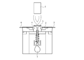
- the valve seat 4 was worn by being repeatedly struck by the valve 3, and the amount of wear was calculated as the receding amount of the contact surface by measuring the shape of the valve seat and the valve before and after the test.
- the valve is SUH alloy (JIS standard: JIS G 4311) and Stellite (registered trademark) # 12 (Cr: 29-31% by mass, C: 1.4-1.8% by mass, W: 8% by mass, balance: Co)
- a size suitable for the above valve seat was used.
- the test conditions were a temperature of 250 ° C. (surface per valve seat), a cam rotation speed of 2000 rpm, and a test time of 5 hours.
- the test results are shown in Table 2 together with the above-mentioned sintered body density (relative density) and HRC hardness.
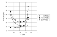
- FIG. 2 is a plot of valve seat wear, valve wear, and their total wear against C% in the base. The amount of wear of the valve is negligible when C% is low, but increases significantly when C% is high.
- the amount of wear of the valve seat is large when C% is low, but even when C% is high, it shows a tendency to increase slightly without decreasing below a certain amount.
- the amount of wear increases rapidly when C is lower than 1.2% by mass, and the amount of wear increases abruptly when C is higher than 1.6% by mass. It was found that the total wear amount of the valve and the valve seat can be kept extremely low in the numerical range of 1.2 to 1.6% by mass of C.
- the sintered body of Comparative Example 4 had a density of 7.16 g / cm 3 and a relative density of 90.8%, which had not been densified. Therefore, the hardness was low and the amount of self-abrasion of the valve seat was large. It was found that the addition of 0.8 mass% or more of P (FeP: about 3.0 mass% or more with respect to the entire sintered alloy) is effective for densification.
- Example 7 Ring-shaped sintering by mixing, molding, and sintering in the same manner as in Example 4 except that 15% by mass of Cr-W-Co-Fe alloy having a Vickers hardness of Hv 980 and an average particle size of 28 ⁇ m was blended as hard particles The body was made.
- the Cr—W—Co—Fe alloy used here has a composition consisting of Cr: 31.8%, W: 22.0%, Co: 8.4%, C: 2.1%, the balance: Fe and inevitable impurities in mass%. Was.
- the density and hardness of the sintered body were measured, and the wear test was performed in the same manner as in Example 4.
- Table 3 shows the matrix composition, hard particle type and mixing ratio
- Table 4 shows the density and hardness of the sintered body and the results of the wear test.
- Example 8 The same mixing as in Example 4 except that 10% by mass of the Fe—Mo—Si alloy used in Example 4 and 5% by mass of the Cr—W—Co—Fe alloy used in Example 7 were mixed as hard particles.
- a ring-shaped sintered body was produced by molding and sintering. The density and hardness of the sintered body were measured, and the wear test was performed in the same manner as in Example 4.
- Table 3 shows the matrix composition, hard particle type and mixing ratio
- Table 4 shows the density and hardness of the sintered body and the results of the abrasion test together with the results of Example 7.
- Example 9 Instead of a vacuum atmosphere at 1120 ° C., except firing at N 2 + H 2 mixed gas atmosphere of 1120 ° C., was prepared in the same manner as the ring-shaped sintered body as in Example 4. The density and hardness of the sintered body were measured, and the wear test was performed in the same manner as in Example 4. Table 3 shows the matrix composition, the type and mixing ratio of the hard particles, and Table 4 shows the density and hardness of the sintered body and the results of the wear test together with the results of Examples 7 and 8. The surface was nitrided by firing in a N 2 + H 2 mixed gas atmosphere, and a high hardness of HRC 46.3 was obtained.
- Comparative Example 5 As Comparative Example 5, a ring-shaped sintered body was produced in the same manner as in Example 4, except that TiN having an average particle diameter of 10 ⁇ m was changed to 10% by mass instead of the hard particles of the intermetallic compound. The density and hardness of the sintered body were measured, and the wear test was performed in the same manner as in Example 4. Table 3 shows the matrix composition, the kind and mixing ratio of the hard particles, and Table 4 shows the density and hardness of the sintered body and the results of the abrasion test together with the results of Examples 7-9. The measured value of hardness in Comparative Example 5 indicates that the high hardness (Hv 2000-2400) of TiN increases the hardness of the sintered body. Further, the wear amount of both the valve seat and the valve tended to be large. The composition components of the entire sintered body are shown in Table 5 together with the data of Examples 1 to 9 and Comparative Examples 1 to 5.
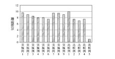
- FIG. 3 shows a relative comparison in which the cutting distance of Comparative Example 5 is 1.
- the present invention in which the intermetallic compound is a hard particle shows excellent machinability, and when C of the iron-based sintered valve seat exceeds 1.6% by mass, the machinability Tended to decrease.
Landscapes
- Chemical & Material Sciences (AREA)
- Engineering & Computer Science (AREA)
- Mechanical Engineering (AREA)
- Materials Engineering (AREA)
- Metallurgy (AREA)
- Organic Chemistry (AREA)
- General Engineering & Computer Science (AREA)
- Physics & Mathematics (AREA)
- Thermal Sciences (AREA)
- Crystallography & Structural Chemistry (AREA)
- Powder Metallurgy (AREA)
Priority Applications (3)
| Application Number | Priority Date | Filing Date | Title |
|---|---|---|---|
| CN201380035048.XA CN104428436B (zh) | 2012-07-06 | 2013-07-03 | 铁基烧结合金制阀座 |
| US14/412,910 US9359921B2 (en) | 2012-07-06 | 2013-07-03 | Sintered iron-based alloy valve seat |
| IN371DEN2015 IN2015DN00371A (enExample) | 2012-07-06 | 2013-07-03 |
Applications Claiming Priority (2)
| Application Number | Priority Date | Filing Date | Title |
|---|---|---|---|
| JP2012152597A JP5462325B2 (ja) | 2012-07-06 | 2012-07-06 | 鉄基焼結合金製バルブシート |
| JP2012-152597 | 2012-07-06 |
Publications (1)
| Publication Number | Publication Date |
|---|---|
| WO2014007278A1 true WO2014007278A1 (ja) | 2014-01-09 |
Family
ID=49882030
Family Applications (1)
| Application Number | Title | Priority Date | Filing Date |
|---|---|---|---|
| PCT/JP2013/068228 Ceased WO2014007278A1 (ja) | 2012-07-06 | 2013-07-03 | 鉄基焼結合金製バルブシート |
Country Status (5)
| Country | Link |
|---|---|
| US (1) | US9359921B2 (enExample) |
| JP (1) | JP5462325B2 (enExample) |
| CN (1) | CN104428436B (enExample) |
| IN (1) | IN2015DN00371A (enExample) |
| WO (1) | WO2014007278A1 (enExample) |
Cited By (1)
| Publication number | Priority date | Publication date | Assignee | Title |
|---|---|---|---|---|
| WO2015141331A1 (ja) * | 2014-03-19 | 2015-09-24 | 株式会社リケン | 鉄基焼結合金製バルブシート |
Families Citing this family (33)
| Publication number | Priority date | Publication date | Assignee | Title |
|---|---|---|---|---|
| JP6508611B2 (ja) * | 2015-03-30 | 2019-05-08 | 日立化成株式会社 | 焼結合金およびその製造方法 |
| DE102015211623A1 (de) * | 2015-06-23 | 2016-12-29 | Mahle International Gmbh | Verfahren zur Herstellung eines Ventilsitzringes |
| US10391557B2 (en) | 2016-05-26 | 2019-08-27 | Kennametal Inc. | Cladded articles and applications thereof |
| CN107838413B (zh) * | 2017-09-30 | 2021-03-16 | 东风商用车有限公司 | 一种重型发动机粉末冶金阀座材料及其制备方法 |
| US10344757B1 (en) | 2018-01-19 | 2019-07-09 | Kennametal Inc. | Valve seats and valve assemblies for fluid end applications |
| US11566718B2 (en) | 2018-08-31 | 2023-01-31 | Kennametal Inc. | Valves, valve assemblies and applications thereof |
| US11236834B2 (en) * | 2019-03-08 | 2022-02-01 | Applied Materials, Inc. | Diaphragm valves and methods of operating same |
| US11353117B1 (en) | 2020-01-17 | 2022-06-07 | Vulcan Industrial Holdings, LLC | Valve seat insert system and method |
| US12049889B2 (en) | 2020-06-30 | 2024-07-30 | Vulcan Industrial Holdings, LLC | Packing bore wear sleeve retainer system |
| US11421680B1 (en) | 2020-06-30 | 2022-08-23 | Vulcan Industrial Holdings, LLC | Packing bore wear sleeve retainer system |
| US11421679B1 (en) | 2020-06-30 | 2022-08-23 | Vulcan Industrial Holdings, LLC | Packing assembly with threaded sleeve for interaction with an installation tool |
| US11384756B1 (en) | 2020-08-19 | 2022-07-12 | Vulcan Industrial Holdings, LLC | Composite valve seat system and method |
| USD980876S1 (en) | 2020-08-21 | 2023-03-14 | Vulcan Industrial Holdings, LLC | Fluid end for a pumping system |
| USD997992S1 (en) | 2020-08-21 | 2023-09-05 | Vulcan Industrial Holdings, LLC | Fluid end for a pumping system |
| USD986928S1 (en) | 2020-08-21 | 2023-05-23 | Vulcan Industrial Holdings, LLC | Fluid end for a pumping system |
| US12366245B1 (en) | 2020-08-27 | 2025-07-22 | Vulcan Industrial Holdings, LLC | Connecting rod assembly for reciprocating pump |
| JP2022050275A (ja) * | 2020-09-17 | 2022-03-30 | 株式会社リケン | 焼結バルブシート |
| US11391374B1 (en) | 2021-01-14 | 2022-07-19 | Vulcan Industrial Holdings, LLC | Dual ring stuffing box |
| US12055221B2 (en) | 2021-01-14 | 2024-08-06 | Vulcan Industrial Holdings, LLC | Dual ring stuffing box |
| US12292120B1 (en) | 2021-02-23 | 2025-05-06 | Vulcan Industrial Holdings, LLC | System and method for valve assembly |
| US11988294B2 (en) | 2021-04-29 | 2024-05-21 | L.E. Jones Company | Sintered valve seat insert and method of manufacture thereof |
| US20240344467A1 (en) * | 2021-07-20 | 2024-10-17 | Nippon Piston Ring Co., Ltd. | Iron-based sintered alloy valve seat insert for internal combustion engine |
| US11846356B1 (en) | 2021-08-18 | 2023-12-19 | Vulcan Industrial Holdings, LLC | Self-locking plug |
| US12510164B1 (en) | 2021-08-18 | 2025-12-30 | Vulcan Industrial Holdings, LLC | Sleeved fluid end |
| JP7794723B2 (ja) * | 2021-10-29 | 2026-01-06 | 日本ピストンリング株式会社 | 鉄基焼結合金製バルブシートおよびその製造方法 |
| US12140240B1 (en) | 2022-01-19 | 2024-11-12 | Vulcan Industrial Holdings, LLC | Gradient material structures and methods of forming the same |
| US12297922B1 (en) | 2022-03-04 | 2025-05-13 | Vulcan Industrial Holdings, LLC | Valve seat with embedded structure and related methods |
| US11434900B1 (en) | 2022-04-25 | 2022-09-06 | Vulcan Industrial Holdings, LLC | Spring controlling valve |
| US11920684B1 (en) | 2022-05-17 | 2024-03-05 | Vulcan Industrial Holdings, LLC | Mechanically or hybrid mounted valve seat |
| USD1113987S1 (en) | 2022-05-20 | 2026-02-17 | Vulcan Industrial Holdings, LLC | Header ring for a pumping system |
| USD1061623S1 (en) | 2022-08-03 | 2025-02-11 | Vulcan Industrial Holdings, LLC | Fluid end for a pumping system |
| CN117120655B (zh) * | 2022-12-09 | 2024-07-09 | 帝伯爱尔株式会社 | 铁基烧结合金阀座 |
| US12292121B2 (en) | 2023-08-10 | 2025-05-06 | Vulcan Industrial Holdings, LLC | Valve member including cavity, and related assemblies, systems, and methods |
Citations (5)
| Publication number | Priority date | Publication date | Assignee | Title |
|---|---|---|---|---|
| JPH06101429A (ja) * | 1992-09-22 | 1994-04-12 | Mitsubishi Materials Corp | 内燃機関用鉛含浸鉄系焼結合金製バルブシート |
| JPH06306409A (ja) * | 1993-04-22 | 1994-11-01 | Mitsubishi Materials Corp | 耐摩耗性のすぐれたFe基焼結合金製バルブガイド部材 |
| JP2002129296A (ja) * | 2000-10-27 | 2002-05-09 | Nippon Piston Ring Co Ltd | バルブシート用鉄基焼結合金材および鉄基焼結合金製バルブシート |
| JP3784003B2 (ja) * | 2001-01-31 | 2006-06-07 | 日立粉末冶金株式会社 | ターボチャージャー用ターボ部品 |
| WO2011105338A1 (ja) * | 2010-02-23 | 2011-09-01 | 株式会社リケン | バルブシート |
Family Cites Families (15)
| Publication number | Priority date | Publication date | Assignee | Title |
|---|---|---|---|---|
| US4129444A (en) * | 1973-01-15 | 1978-12-12 | Cabot Corporation | Power metallurgy compacts and products of high performance alloys |
| JPS5830361B2 (ja) * | 1979-02-26 | 1983-06-29 | 日本ピストンリング株式会社 | 内燃機関用耐摩耗性部材の製造方法 |
| JPS55145151A (en) * | 1979-04-26 | 1980-11-12 | Nippon Piston Ring Co Ltd | Wear resistant sintered alloy material for internal combustion engine |
| JPS6119762A (ja) | 1984-07-06 | 1986-01-28 | Riken Corp | 耐摩耗焼結合金 |
| JPS6196058A (ja) * | 1984-10-15 | 1986-05-14 | Toyota Motor Corp | 動弁系摺動部材とその製造方法 |
| JP2506333B2 (ja) * | 1986-03-12 | 1996-06-12 | 日産自動車株式会社 | 耐摩耗性鉄基焼結合金 |
| JP2777373B2 (ja) * | 1988-06-28 | 1998-07-16 | 日産自動車株式会社 | 耐熱耐摩耗性鉄基焼結合金 |
| JPH05117703A (ja) * | 1991-09-05 | 1993-05-14 | Kawasaki Steel Corp | 粉末冶金用鉄基粉末組成物およびその製造方法ならびに鉄系焼結材料の製造方法 |
| US5507257A (en) | 1993-04-22 | 1996-04-16 | Mitsubishi Materials Corporation | Value guide member formed of Fe-based sintered alloy having excellent wear and abrasion resistance |
| JP3343313B2 (ja) * | 1995-06-30 | 2002-11-11 | 株式会社フジキン | ダイヤフラム弁 |
| JP3952344B2 (ja) * | 1998-12-28 | 2007-08-01 | 日本ピストンリング株式会社 | バルブシート用耐摩耗性鉄基焼結合金材および鉄基焼結合金製バルブシート |
| DE60323795D1 (de) * | 2002-08-16 | 2008-11-13 | Alloy Technology Solutions Inc | Verschleissbeständige und korrosionsbeständige austenitische Eisenbasislegierung |
| JP4650832B2 (ja) * | 2002-12-20 | 2011-03-16 | アプライド マテリアルズ インコーポレイテッド | 半導体処理装置に使用するための拡散接合されたガス分配アッセンブリを製造する方法 |
| JP4423254B2 (ja) * | 2005-12-02 | 2010-03-03 | 株式会社神戸製鋼所 | コイリング性と耐水素脆化特性に優れた高強度ばね鋼線 |
| US20080146467A1 (en) * | 2006-01-26 | 2008-06-19 | Takemori Takayama | Sintered Material, Ferrous Sintered Sliding Material, Producing Method of the Same, Sliding Member, Producing Method of the Same and Coupling Device |
-
2012
- 2012-07-06 JP JP2012152597A patent/JP5462325B2/ja not_active Expired - Fee Related
-
2013
- 2013-07-03 IN IN371DEN2015 patent/IN2015DN00371A/en unknown
- 2013-07-03 US US14/412,910 patent/US9359921B2/en not_active Expired - Fee Related
- 2013-07-03 WO PCT/JP2013/068228 patent/WO2014007278A1/ja not_active Ceased
- 2013-07-03 CN CN201380035048.XA patent/CN104428436B/zh not_active Expired - Fee Related
Patent Citations (5)
| Publication number | Priority date | Publication date | Assignee | Title |
|---|---|---|---|---|
| JPH06101429A (ja) * | 1992-09-22 | 1994-04-12 | Mitsubishi Materials Corp | 内燃機関用鉛含浸鉄系焼結合金製バルブシート |
| JPH06306409A (ja) * | 1993-04-22 | 1994-11-01 | Mitsubishi Materials Corp | 耐摩耗性のすぐれたFe基焼結合金製バルブガイド部材 |
| JP2002129296A (ja) * | 2000-10-27 | 2002-05-09 | Nippon Piston Ring Co Ltd | バルブシート用鉄基焼結合金材および鉄基焼結合金製バルブシート |
| JP3784003B2 (ja) * | 2001-01-31 | 2006-06-07 | 日立粉末冶金株式会社 | ターボチャージャー用ターボ部品 |
| WO2011105338A1 (ja) * | 2010-02-23 | 2011-09-01 | 株式会社リケン | バルブシート |
Cited By (3)
| Publication number | Priority date | Publication date | Assignee | Title |
|---|---|---|---|---|
| WO2015141331A1 (ja) * | 2014-03-19 | 2015-09-24 | 株式会社リケン | 鉄基焼結合金製バルブシート |
| JP2015178650A (ja) * | 2014-03-19 | 2015-10-08 | 株式会社リケン | 鉄基焼結合金製バルブシート |
| US10233793B2 (en) | 2014-03-19 | 2019-03-19 | Kabushiki Kaisha Riken | Valve seat of sintered iron-based alloy |
Also Published As
| Publication number | Publication date |
|---|---|
| IN2015DN00371A (enExample) | 2015-06-12 |
| CN104428436A (zh) | 2015-03-18 |
| US9359921B2 (en) | 2016-06-07 |
| US20150152753A1 (en) | 2015-06-04 |
| JP5462325B2 (ja) | 2014-04-02 |
| CN104428436B (zh) | 2016-10-26 |
| JP2014015645A (ja) | 2014-01-30 |
Similar Documents
| Publication | Publication Date | Title |
|---|---|---|
| JP5462325B2 (ja) | 鉄基焼結合金製バルブシート | |
| JP6305811B2 (ja) | バルブシート用鉄基焼結合金材およびその製造方法 | |
| JP5887374B2 (ja) | 鉄基焼結合金製バルブシート | |
| US9212572B2 (en) | Sintered valve guide and production method therefor | |
| JP3926320B2 (ja) | 鉄基焼結合金製バルブシートおよびその製造方法 | |
| JP3520093B2 (ja) | 二次硬化型高温耐摩耗性焼結合金 | |
| JP5658804B1 (ja) | 焼結合金製バルブガイド及びその製造方法 | |
| JP4584158B2 (ja) | 内燃機関用鉄基焼結合金製バルブシート材 | |
| JP2011174112A (ja) | バルブシート | |
| WO2012099239A1 (ja) | 鉄基焼結合金製バルブシート | |
| JP6392796B2 (ja) | 耐摩耗性鉄基焼結合金の製造方法、焼結合金用成形体、および耐摩耗性鉄基焼結合金 | |
| JP7188434B2 (ja) | 焼結バルブガイド及びその製造方法 | |
| JP6352959B2 (ja) | 耐摩耗性鉄基焼結合金の製造方法、焼結合金用成形体、および耐摩耗性鉄基焼結合金 | |
| JP2018044226A (ja) | 耐摩耗性鉄基焼結合金の製造方法および耐摩耗性鉄基焼結合金 | |
| JP6392530B2 (ja) | 鉄基焼結合金製バルブシート | |
| JP6842345B2 (ja) | 耐摩耗性鉄基焼結合金の製造方法 | |
| JP6528899B2 (ja) | 粉末冶金用混合粉および焼結体の製造方法 | |
| JPH09209095A (ja) | 耐摩耗性に優れた鉄基焼結合金 | |
| JP2013173961A (ja) | 鉄基焼結合金製バルブシート | |
| JP2006037138A (ja) | 鉄基焼結合金製バルブシート | |
| JPH06158217A (ja) | 耐摩耗性のすぐれたFe基焼結合金製バルブガイド部材 | |
| JPH03134139A (ja) | バルブシート用鉄基焼結合金 | |
| JPH06158242A (ja) | 耐摩耗性のすぐれたFe基焼結合金製バルブガイド部材 |
Legal Events
| Date | Code | Title | Description |
|---|---|---|---|
| 121 | Ep: the epo has been informed by wipo that ep was designated in this application |
Ref document number: 13813178 Country of ref document: EP Kind code of ref document: A1 |
|
| WWE | Wipo information: entry into national phase |
Ref document number: 14412910 Country of ref document: US |
|
| NENP | Non-entry into the national phase |
Ref country code: DE |
|
| 122 | Ep: pct application non-entry in european phase |
Ref document number: 13813178 Country of ref document: EP Kind code of ref document: A1 |