WO2014007278A1 - Valve seat made of iron-base sintered alloy - Google Patents
Valve seat made of iron-base sintered alloy Download PDFInfo
- Publication number
- WO2014007278A1 WO2014007278A1 PCT/JP2013/068228 JP2013068228W WO2014007278A1 WO 2014007278 A1 WO2014007278 A1 WO 2014007278A1 JP 2013068228 W JP2013068228 W JP 2013068228W WO 2014007278 A1 WO2014007278 A1 WO 2014007278A1
- Authority
- WO
- WIPO (PCT)
- Prior art keywords
- valve seat
- iron
- alloy
- mass
- based sintered
- Prior art date
Links
Images
Classifications
-
- F—MECHANICAL ENGINEERING; LIGHTING; HEATING; WEAPONS; BLASTING
- F01—MACHINES OR ENGINES IN GENERAL; ENGINE PLANTS IN GENERAL; STEAM ENGINES
- F01L—CYCLICALLY OPERATING VALVES FOR MACHINES OR ENGINES
- F01L3/00—Lift-valve, i.e. cut-off apparatus with closure members having at least a component of their opening and closing motion perpendicular to the closing faces; Parts or accessories thereof
- F01L3/02—Selecting particular materials for valve-members or valve-seats; Valve-members or valve-seats composed of two or more materials
-
- C—CHEMISTRY; METALLURGY
- C21—METALLURGY OF IRON
- C21D—MODIFYING THE PHYSICAL STRUCTURE OF FERROUS METALS; GENERAL DEVICES FOR HEAT TREATMENT OF FERROUS OR NON-FERROUS METALS OR ALLOYS; MAKING METAL MALLEABLE, e.g. BY DECARBURISATION OR TEMPERING
- C21D6/00—Heat treatment of ferrous alloys
- C21D6/002—Heat treatment of ferrous alloys containing Cr
-
- C—CHEMISTRY; METALLURGY
- C22—METALLURGY; FERROUS OR NON-FERROUS ALLOYS; TREATMENT OF ALLOYS OR NON-FERROUS METALS
- C22C—ALLOYS
- C22C33/00—Making ferrous alloys
- C22C33/02—Making ferrous alloys by powder metallurgy
-
- C—CHEMISTRY; METALLURGY
- C22—METALLURGY; FERROUS OR NON-FERROUS ALLOYS; TREATMENT OF ALLOYS OR NON-FERROUS METALS
- C22C—ALLOYS
- C22C33/00—Making ferrous alloys
- C22C33/02—Making ferrous alloys by powder metallurgy
- C22C33/0257—Making ferrous alloys by powder metallurgy characterised by the range of the alloying elements
- C22C33/0278—Making ferrous alloys by powder metallurgy characterised by the range of the alloying elements with at least one alloying element having a minimum content above 5%
- C22C33/0285—Making ferrous alloys by powder metallurgy characterised by the range of the alloying elements with at least one alloying element having a minimum content above 5% with Cr, Co, or Ni having a minimum content higher than 5%
-
- C—CHEMISTRY; METALLURGY
- C22—METALLURGY; FERROUS OR NON-FERROUS ALLOYS; TREATMENT OF ALLOYS OR NON-FERROUS METALS
- C22C—ALLOYS
- C22C38/00—Ferrous alloys, e.g. steel alloys
-
- C—CHEMISTRY; METALLURGY
- C22—METALLURGY; FERROUS OR NON-FERROUS ALLOYS; TREATMENT OF ALLOYS OR NON-FERROUS METALS
- C22C—ALLOYS
- C22C38/00—Ferrous alloys, e.g. steel alloys
- C22C38/002—Ferrous alloys, e.g. steel alloys containing In, Mg, or other elements not provided for in one single group C22C38/001 - C22C38/60
-
- C—CHEMISTRY; METALLURGY
- C22—METALLURGY; FERROUS OR NON-FERROUS ALLOYS; TREATMENT OF ALLOYS OR NON-FERROUS METALS
- C22C—ALLOYS
- C22C38/00—Ferrous alloys, e.g. steel alloys
- C22C38/02—Ferrous alloys, e.g. steel alloys containing silicon
-
- C—CHEMISTRY; METALLURGY
- C22—METALLURGY; FERROUS OR NON-FERROUS ALLOYS; TREATMENT OF ALLOYS OR NON-FERROUS METALS
- C22C—ALLOYS
- C22C38/00—Ferrous alloys, e.g. steel alloys
- C22C38/18—Ferrous alloys, e.g. steel alloys containing chromium
- C22C38/22—Ferrous alloys, e.g. steel alloys containing chromium with molybdenum or tungsten
-
- C—CHEMISTRY; METALLURGY
- C22—METALLURGY; FERROUS OR NON-FERROUS ALLOYS; TREATMENT OF ALLOYS OR NON-FERROUS METALS
- C22C—ALLOYS
- C22C38/00—Ferrous alloys, e.g. steel alloys
- C22C38/18—Ferrous alloys, e.g. steel alloys containing chromium
- C22C38/24—Ferrous alloys, e.g. steel alloys containing chromium with vanadium
-
- C—CHEMISTRY; METALLURGY
- C22—METALLURGY; FERROUS OR NON-FERROUS ALLOYS; TREATMENT OF ALLOYS OR NON-FERROUS METALS
- C22C—ALLOYS
- C22C38/00—Ferrous alloys, e.g. steel alloys
- C22C38/18—Ferrous alloys, e.g. steel alloys containing chromium
- C22C38/30—Ferrous alloys, e.g. steel alloys containing chromium with cobalt
-
- C—CHEMISTRY; METALLURGY
- C22—METALLURGY; FERROUS OR NON-FERROUS ALLOYS; TREATMENT OF ALLOYS OR NON-FERROUS METALS
- C22C—ALLOYS
- C22C38/00—Ferrous alloys, e.g. steel alloys
- C22C38/18—Ferrous alloys, e.g. steel alloys containing chromium
- C22C38/36—Ferrous alloys, e.g. steel alloys containing chromium with more than 1.7% by weight of carbon
-
- F—MECHANICAL ENGINEERING; LIGHTING; HEATING; WEAPONS; BLASTING
- F01—MACHINES OR ENGINES IN GENERAL; ENGINE PLANTS IN GENERAL; STEAM ENGINES
- F01L—CYCLICALLY OPERATING VALVES FOR MACHINES OR ENGINES
- F01L3/00—Lift-valve, i.e. cut-off apparatus with closure members having at least a component of their opening and closing motion perpendicular to the closing faces; Parts or accessories thereof
- F01L3/22—Valve-seats not provided for in preceding subgroups of this group; Fixing of valve-seats
-
- F—MECHANICAL ENGINEERING; LIGHTING; HEATING; WEAPONS; BLASTING
- F16—ENGINEERING ELEMENTS AND UNITS; GENERAL MEASURES FOR PRODUCING AND MAINTAINING EFFECTIVE FUNCTIONING OF MACHINES OR INSTALLATIONS; THERMAL INSULATION IN GENERAL
- F16K—VALVES; TAPS; COCKS; ACTUATING-FLOATS; DEVICES FOR VENTING OR AERATING
- F16K25/00—Details relating to contact between valve members and seat
- F16K25/005—Particular materials for seats or closure elements
-
- B—PERFORMING OPERATIONS; TRANSPORTING
- B22—CASTING; POWDER METALLURGY
- B22F—WORKING METALLIC POWDER; MANUFACTURE OF ARTICLES FROM METALLIC POWDER; MAKING METALLIC POWDER; APPARATUS OR DEVICES SPECIALLY ADAPTED FOR METALLIC POWDER
- B22F5/00—Manufacture of workpieces or articles from metallic powder characterised by the special shape of the product
- B22F5/10—Manufacture of workpieces or articles from metallic powder characterised by the special shape of the product of articles with cavities or holes, not otherwise provided for in the preceding subgroups
- B22F5/106—Tube or ring forms
-
- C—CHEMISTRY; METALLURGY
- C21—METALLURGY OF IRON
- C21D—MODIFYING THE PHYSICAL STRUCTURE OF FERROUS METALS; GENERAL DEVICES FOR HEAT TREATMENT OF FERROUS OR NON-FERROUS METALS OR ALLOYS; MAKING METAL MALLEABLE, e.g. BY DECARBURISATION OR TEMPERING
- C21D2211/00—Microstructure comprising significant phases
- C21D2211/004—Dispersions; Precipitations
-
- C—CHEMISTRY; METALLURGY
- C21—METALLURGY OF IRON
- C21D—MODIFYING THE PHYSICAL STRUCTURE OF FERROUS METALS; GENERAL DEVICES FOR HEAT TREATMENT OF FERROUS OR NON-FERROUS METALS OR ALLOYS; MAKING METAL MALLEABLE, e.g. BY DECARBURISATION OR TEMPERING
- C21D2211/00—Microstructure comprising significant phases
- C21D2211/008—Martensite
Abstract
In order to provide a valve seat which is made of an iron-base sintered alloy having excellent abrasion resistance and machinability and which is usable in a diesel engine accommodating an output increase, the present invention comprises: using an intermetallic compound having a Vickers hardness (Hv) of 800 to 1200; and adjusting the contents of C and P in the composition of an iron-base sintered valve seat to 1.2 to 1.6 mass% and 0.80 to 1.35 mass% respectively.
Description
本発明は、内燃機関のバルブシートに関し、特に高出力用の高負荷ディーゼルエンジンに使用可能な、耐摩耗性と被削性の両方に優れた鉄基焼結合金製バルブシートに関する。
The present invention relates to a valve seat for an internal combustion engine, and more particularly, to a valve seat made of an iron-based sintered alloy that can be used for a high-load, high-load diesel engine and is excellent in both wear resistance and machinability.
バルブシートは、内燃機関のシリンダヘッドに装着され、高温環境下でバルブにより繰り返し打撃を受けるため、その耐摩耗性、耐熱性などを向上させるべく種々の改良がなされている。特に高出力用の高負荷ディーゼルエンジンでは、環境対応のための燃焼効率の向上により金属接触を伴うバルブシート材料への負荷が益々強くなる傾向にあり、バルブシートには、幅広い使用温度において、従来にも増す耐摩耗性の向上が求められている。これまで、ディーゼルエンジン用バルブシートとして、例えば、特開昭61-19762には、熱負荷や機械的負荷に耐え、且つ耐摩耗性を確保するため、重量%で、C:1.0~3.0%、Si:0.2~1.0%、Cr:5.0~20%、Mo:0.5~2.0%、V:0.3~3.0%、B、P及びSの1種又は2種以上が合計で0.02~0.5%、残部が実質的にFeからなる基地中に、TiN粒子が気孔を除く部分の面積比で2~30%分散する窒化チタン粒子を分散した耐摩耗性焼結合金が開示されている。
Since the valve seat is mounted on the cylinder head of the internal combustion engine and repeatedly hit by the valve in a high temperature environment, various improvements have been made to improve its wear resistance and heat resistance. Especially in high-load high-load diesel engines, the load on the valve seat material with metal contact tends to become stronger due to the improvement of combustion efficiency for environmental reasons. There is also a need for improved wear resistance. Conventionally, as a valve seat for a diesel engine, for example, in Japanese Patent Application Laid-Open No. 61-19762, in order to withstand heat load and mechanical load and to ensure wear resistance, C: 1.0 to 3.0% by weight, Si: 0.2 to 1.0%, Cr: 5.0 to 20%, Mo: 0.5 to 2.0%, V: 0.3 to 3.0%, one or more of B, P and S total 0.02 to 0.5%, the balance A wear-resistant sintered alloy is disclosed in which titanium nitride particles in which TiN particles are dispersed in an area ratio of the portion excluding the pores in a base substantially made of Fe are dispersed by 2 to 30%.
しかしながら、TiNを分散させたものは、TiNが基地と密着性が高くないために脱落することにより、被削性が悪く加工が非常に困難になって、高コストな材料となってしまう。また、比較的相手材攻撃性が強いため、バルブを摩耗させてしまうという問題もある。すなわち、ディーゼルエンジン用バルブシートにおいては、被削性に加え、いわゆる相手材攻撃性も含めた耐摩耗性の向上が求められている。
However, in the case where TiN is dispersed, TiN is not highly adhesive with the base and falls off, so that machinability is poor and machining becomes very difficult, resulting in an expensive material. Moreover, since the counterpart material is relatively strong in attacking property, there is a problem that the valve is worn. That is, in a diesel engine valve seat, in addition to machinability, there is a demand for improved wear resistance including so-called mating material attack.
上記問題に鑑み、本発明は、高出力化に対応したディーゼルエンジンに使用する高い耐摩耗性及び優れた被削性を有する鉄基焼結合金製バルブシートを提供することを課題とする。
In view of the above problems, an object of the present invention is to provide an iron-based sintered alloy valve seat having high wear resistance and excellent machinability for use in a diesel engine compatible with high output.
また、焼結合金は少なからず気孔を有しており、気孔の存在によりいわゆる断続切削を誘起し、工具に衝撃を与えて欠損や工具摩耗を促進させてしまう。従って、被削性を改善するには、焼結合金の緻密化も重要な側面となる。
Also, the sintered alloy has not a few pores, and the presence of the pores induces so-called interrupted cutting, and impacts the tool to promote chipping and tool wear. Therefore, in order to improve machinability, densification of the sintered alloy is also an important aspect.
本発明者達は、鉄基焼結合金製バルブシートについて鋭意研究の結果、ビッカース硬さHvが800~1200の金属間化合物を使用し、且つ、鉄基焼結バルブシートの組成のうち、特にC及びPについて、質量%でそれぞれ1.2~1.6%及び0.80~1.35%の範囲とすることによって、耐摩耗性と被削性の両方に優れた鉄基焼結合金製バルブシートが得られることに想到した。
As a result of earnest research on the valve seat made of iron-based sintered alloy, the present inventors have used an intermetallic compound having a Vickers hardness of Hv of 800 to 1200, and among the compositions of the iron-based sintered valve seat, For C and P, by setting the mass percentages in the range of 1.2 to 1.6% and 0.80 to 1.35% respectively, an iron-based sintered alloy valve seat excellent in both wear resistance and machinability can be obtained. I came up with it.
すなわち、本発明の鉄基焼結合金製バルブシートは、基地中に、平均粒径5~200μm、ビッカース硬さHv 800~1200の金属間化合物からなる硬質粒子を体積%で5~14%分散させた鉄基焼結合金製バルブシートであって、前記基地の組成がC、Si、Cr、Mo、V、P、並びに残部がFe及び不可避的不純物からなり、前記C及び前記Pは質量%で前記鉄基焼結バルブシートに対しC:1.2~1.6%、P:0.80~1.35%であることを特徴とする。前記基地の組成としては、質量%で、C:1.3~1.85%、Si:0.4~0.8%、Cr:10.0~13.0%、Mo:0.8~1.2%、V:1.7~2.2%、P:0.80~1.72%、並びに残部:Fe及び不可避的不純物からなるように配合した原料粉末を使用することが好ましい。
That is, the iron-based sintered alloy valve seat according to the present invention disperses 5 to 14% by volume of hard particles made of an intermetallic compound having an average particle diameter of 5 to 200 μm and a Vickers hardness of Hv 800 to 1200 in the base. A valve seat made of an iron-based sintered alloy, wherein the matrix composition is C, Si, Cr, Mo, V, P, and the balance is Fe and inevitable impurities, and the C and P are in mass%. And C: 1.2-1.6% and P: 0.80-1.35% with respect to the iron-based sintered valve seat. The composition of the base is, by mass, C: 1.3 to 1.85%, Si: 0.4 to 0.8%, Cr: 10.0 to 13.0%, Mo: 0.8 to 1.2%, V: 1.7 to 2.2%, P: 0.80 to It is preferable to use a raw material powder blended so as to be composed of 1.72% and the balance: Fe and inevitable impurities.
前記硬質粒子は、Fe-Mo-Si合金及び/又はCr-W-Co-Fe合金からなることが好ましく、前記Fe-Mo-Si合金は、質量%で、Mo:40~70%、Si:0.4~2.0%、C:0.1%以下、並びに残部:Fe及び不可避的不純物、また前記Cr-W-Co-Fe合金は、質量%で、Cr:27~33%、W:22~28%、Co:8~12%、並びに残部:Fe及び不可避的不純物からなることがさらに好ましい。硬質粒子にFe-Mo-Si合金を選択した場合は、鉄基焼結バルブシートの組成のうち、Si、Cr、Mo、Vが質量%で鉄基焼結バルブシートに対しSi:0.5~0.9%、Cr:8.0~11.0%、Mo:5.0~10.0%、及びV:1.4~1.9%であることがより好ましい。
The hard particles are preferably made of an Fe—Mo—Si alloy and / or a Cr—W—Co—Fe alloy, and the Fe—Mo—Si alloy is in mass%, Mo: 40 to 70%, Si: 0.4 to 2.0%, C: 0.1% or less, and the balance: Fe and inevitable impurities, and the Cr-W-Co-Fe alloy is, in mass%, Cr: 27-33%, W: 22-28%, More preferably, it is composed of Co: 8 to 12%, and the balance: Fe and inevitable impurities. When an Fe-Mo-Si alloy is selected for the hard particles, Si, Cr, Mo, V in the composition of the iron-based sintered valve seat, and Si: 0.5 to 0.9 with respect to the iron-based sintered valve seat %, Cr: 8.0 to 11.0%, Mo: 5.0 to 10.0%, and V: 1.4 to 1.9% are more preferable.
また、液相焼結による緻密化に基づき、耐摩耗性と被削性の両方に優れるという観点で、密度が7.5~7.8 g/cm3であることが好ましい。
Further, based on densification by liquid phase sintering, the density is preferably 7.5 to 7.8 g / cm 3 from the viewpoint of being excellent in both wear resistance and machinability.
本発明の鉄基焼結合金製バルブシートは、ビッカース硬さHv 800~1200の金属間化合物からなる硬質粒子を体積%で5~14%分散し、また、鉄基焼結バルブシートの組成のうち特にCについて、質量%で1.2~1.6%の範囲とすることによって、耐摩耗性と被削性の両方を備えたディーゼルエンジン用バルブシートとして使用することが可能となる。さらに、鉄基焼結バルブシートに対し質量%で0.80~1.35%の範囲のPの添加は、液相焼結による緻密化に寄与し、結果的に、硬質粒子の脱落を抑止し、また断続切削を回避して、耐摩耗性及び被削性の両方に貢献する。さらに樹脂含浸等の封孔処理による被削性向上対策も必須とする必要がなくなり、コスト低減に貢献する。
In the iron-based sintered alloy valve seat of the present invention, 5-14% by volume of hard particles made of an intermetallic compound having a Vickers hardness of Hv 800-1200 are dispersed, and the composition of the iron-based sintered valve seat is In particular, C can be used as a valve seat for a diesel engine having both wear resistance and machinability by adjusting the mass% to 1.2 to 1.6%. Furthermore, the addition of P in the range of 0.80 to 1.35% by mass with respect to the iron-based sintered valve seat contributes to densification by liquid phase sintering, and as a result, the hard particles are prevented from falling off and intermittently. Avoids cutting and contributes to both wear resistance and machinability. Furthermore, it is not necessary to make a machinability improvement measure by sealing treatment such as resin impregnation, which contributes to cost reduction.
本発明の鉄基焼結合金製バルブシートは、基地と、基地中に分散した金属間化合物からなる硬質粒子で構成されている。金属間化合物からなる硬質粒子は、5~200μmの平均粒径と、Hv 800~1200のビッカース硬さを有する。ビッカース硬さがHv 800未満では、耐摩耗性が低下し、一方Hv 1200を超えると、靱性が低下してバルブシートに発生する欠けやクラックが増加し、硬質粒子も脱落しやすくなる。また、平均粒径5μm未満では、耐摩耗性に対する効果がほとんど無く、一方200μmを超えると、バルブシートの成形性が悪くなり、密度が低下して耐摩耗性が低下する。硬質粒子の分散量は体積%で5~14%とする。硬質粒子の分散量が5体積%未満では耐摩耗性に対する効果がなく、14体積%を超えると緻密化を阻害し、被削性を低下させ、相手攻撃性を増大させてしまうので好ましくない。
The valve seat made of an iron-based sintered alloy according to the present invention is composed of a base and hard particles made of an intermetallic compound dispersed in the base. Hard particles made of an intermetallic compound have an average particle diameter of 5 to 200 μm and a Vickers hardness of Hv 800 to 1200. When the Vickers hardness is less than Hv 800, the wear resistance is lowered. On the other hand, when the Vickers hardness is more than Hv 1200, the toughness is reduced, the chipping and cracks generated in the valve seat are increased, and the hard particles are easily dropped. On the other hand, when the average particle size is less than 5 μm, there is almost no effect on the wear resistance. On the other hand, when it exceeds 200 μm, the formability of the valve seat is deteriorated, the density is lowered, and the wear resistance is lowered. The dispersion amount of hard particles is 5 to 14% by volume. If the dispersion amount of hard particles is less than 5% by volume, there is no effect on the wear resistance, and if it exceeds 14% by volume, densification is inhibited, machinability is lowered, and the opponent aggression is increased.
硬質粒子として使用できる金属間化合物としては、Fe基材料としては、Fe-Mo合金、Fe-Mo-Si合金、Fe-W合金、Fe-Cr合金、Fe-Si合金、Fe-B合金、Co基材料としては、Co-W-Cr合金、Co-Si-Cr-Mo-Ni合金、Co-Mo-Cr-Si合金、Co-Cr-Ni-Fe合金等があげられる。なかでもFe-Mo-Si合金及び/又はCr-W-Co-Fe合金が好ましく、Fe-Mo-Si合金は、質量%で、Mo:40~70%、Si:0.4~2.0%、C:0.1%以下、及び残部:Fe及び不可避的不純物、またCr-W-Co-Fe合金は、質量%で、Cr:27~33%、W:22~28%、Co:8~12%、C:1.7~2.3%、及び残部:Fe及び不可避的不純物からなることが好ましい。
As intermetallic compounds that can be used as hard particles, Fe-based materials include Fe-Mo alloy, Fe-Mo-Si alloy, Fe-W alloy, Fe-Cr alloy, Fe-Si alloy, Fe-B alloy, Co Examples of the base material include a Co—W—Cr alloy, a Co—Si—Cr—Mo—Ni alloy, a Co—Mo—Cr—Si alloy, and a Co—Cr—Ni—Fe alloy. Among these, Fe-Mo-Si alloy and / or Cr-W-Co-Fe alloy are preferable, and Fe-Mo-Si alloy is in mass%, Mo: 40-70%, Si: 0.4-2.0%, C: 0.1% or less, and the balance: Fe and inevitable impurities, and Cr-W-Co-Fe alloy is in mass%, Cr: 27-33%, W: 22-28%, Co: 8-12%, C : 1.7 to 2.3%, and the balance: Fe and inevitable impurities are preferable.
硬質粒子を除いた基地は、その組成がC、Si、Cr、Mo、V、P、並びに残部がFe及び不可避的不純物からなる組成を有する。その中のC及びPは鉄基焼結バルブシート全体に対して質量%でC:1.2~1.6%、P:0.80~1.35%とする。
The base excluding hard particles has a composition in which the composition is C, Si, Cr, Mo, V, P, and the balance is Fe and inevitable impurities. Among them, C and P are C: 1.2 to 1.6% and P: 0.80 to 1.35% in mass% with respect to the entire iron-based sintered valve seat.
Cは、一般に、基地に固溶して基地を強化するとともに、他の合金元素と結合して炭化物を形成し、耐摩耗性を向上させる。本発明では、鉄基焼結バルブシートに対して、Cが1.2質量%未満では、軟らかいフェライトが生成して所定の硬さを得ることができずに耐摩耗性が不足し、1.6質量%を超えると炭化物が過剰に生成してバルブ攻撃性が著しく高くなる。よって、鉄基焼結バルブシートのCの含有量は1.2~1.6質量%とする。なお、硬質粒子を除いた基地に含まれるCの含有量は1.3~1.85質量%であることが好ましい。
C generally dissolves in the base to strengthen the base and combines with other alloy elements to form carbides and improve wear resistance. In the present invention, with respect to the iron-based sintered valve seat, if C is less than 1.2% by mass, soft ferrite is generated and a predetermined hardness cannot be obtained, resulting in insufficient wear resistance and 1.6% by mass. When it exceeds, carbide | carbonized_material will produce | generate excessively and valve attack property will become remarkably high. Therefore, the content of C in the iron-based sintered valve seat is set to 1.2 to 1.6% by mass. The content of C contained in the base excluding the hard particles is preferably 1.3 to 1.85% by mass.
また、PはFeP(26.6質量%P)として添加され、焼結温度で液相を生成し、緻密化を促進する。Pは、B及びSに比較して鉄基焼結合金に及ぼす脆化作用が小さいため、Pのみを選択した場合、比較的多量のPを導入することが可能となる。本発明では鉄基焼結バルブシートに対して、Pが0.80質量%(FePとして鉄基焼結バルブシート全体に対し約3質量%)未満では緻密化の効果が低く、1.35質量%(FePとして鉄基焼結バルブシート全体に対し約5質量%)を超えると焼戻し脆性等の好ましくない影響が出てくるため、0.80~1.35質量%(FePとして鉄基焼結バルブシート全体に対し3~5質量%)とする。最適な量のP(FeP)の添加により、本発明の鉄基焼結合金は緻密化が促進され、密度が7.5~7.8 g/cm3又は相対密度にして95%以上まで緻密化することが可能となる。このレベルまで緻密化できると従来の被削性改善のために行われていた樹脂等による封孔処理は、必須とする必要がなくなる。もちろん封孔処理を妨げるものではない。なお、硬質粒子を除いた基地に含まれるPの含有量としてはP:0.80~1.72質量%であることが好ましい。
P is added as FeP (26.6% by mass P) to generate a liquid phase at the sintering temperature and promote densification. Since P has a smaller embrittlement effect on the iron-based sintered alloy than B and S, when only P is selected, a relatively large amount of P can be introduced. In the present invention, if the P content is less than 0.80% by mass (as FeP, about 3% by mass with respect to the entire iron-based sintered valve seat), the effect of densification is low, and 1.35% by mass (as FeP). Exceeding approximately 5% by mass of the iron-based sintered valve seat) causes undesirable effects such as tempering brittleness, so 0.80 to 1.35% by mass (FeP is 3 to 5% of the total iron-based sintered valve seat) Mass%). By adding an optimal amount of P (FeP), the iron-based sintered alloy of the present invention can be densified, and the density can be increased to 7.5 to 7.8 g / cm 3 or a relative density of 95% or more. It becomes possible. If it can be densified to this level, the sealing treatment with a resin or the like, which has been performed for improving the machinability in the past, is no longer necessary. Of course, this does not prevent the sealing process. The content of P contained in the base excluding the hard particles is preferably P: 0.80 to 1.72% by mass.
硬質粒子を除いた基地に含まれるSiは、Crの存在下で液相生成温度を下げ、炭化物の粗大化を抑制し、組織を微細化させる。添加量としては0.4~0.8質量%が好ましい。また、Cr、Mo、Vは、いずれもその一部は基地に固溶して基地を強化するとともに、残部はCと結合して炭化物を形成し、耐摩耗性を向上させる。なお、基地に固溶したCrは耐食性を改善し、Moは焼入性と高温強度を高める。また、Vは、特に微細で硬い炭化物を形成して基地を強化し、耐摩耗性の向上に貢献する。Cr、Mo、Vの量が少なすぎれば、これらの効果が不足するが、硬質粒子を除いた基地のCr、Mo、Vの組成としては、それぞれ質量%で、Crが10~13%、Moが0.8~1.2%、Vが1.7~2.2%となるように配合した原料粉末を使用することが好ましい。さらに、硬質粒子を構成する合金成分は焼成中に基地中に拡散し得るため、硬質粒子と基地の界面は良好な結合界面を有し、また最終的な鉄基焼結バルブシートの基地の合金成分は、配合した合金成分の量よりも多く、より強化された状態になる。特にMoは硬質粒子から基地中に拡散しやすい。
Si contained in the base excluding hard particles lowers the liquid phase formation temperature in the presence of Cr, suppresses coarsening of carbides, and refines the structure. The addition amount is preferably 0.4 to 0.8% by mass. In addition, Cr, Mo, and V are all partly dissolved in the matrix to strengthen the matrix, and the remainder is combined with C to form carbides and improve wear resistance. In addition, Cr dissolved in the base improves corrosion resistance, and Mo increases hardenability and high temperature strength. V also strengthens the base by forming fine and hard carbides, and contributes to improved wear resistance. If the amount of Cr, Mo, V is too small, these effects will be insufficient, but the composition of the base Cr, Mo, V excluding hard particles is mass%, Cr is 10-13%, Mo It is preferable to use a raw material powder blended so that is 0.8 to 1.2% and V is 1.7 to 2.2%. Furthermore, since the alloy components constituting the hard particles can diffuse into the matrix during firing, the interface between the hard particles and the matrix has a good bonding interface, and the base alloy of the final iron-based sintered valve seat The component is more strengthened than the amount of the alloying component blended. In particular, Mo easily diffuses from hard particles into the matrix.
硬質粒子にFe-Mo-Si合金を使用した場合は、Si、Cr、Mo、及びVは、鉄基焼結バルブシートに対し質量%でSi:0.5~0.9%、Cr:8.0~11.0%、Mo:5.0~10.0%、及びV:1.4~1.9%の組成となることが好ましい。
When Fe-Mo-Si alloy is used for the hard particles, Si, Cr, Mo, and V are in mass% with respect to the iron-based sintered valve seat, Si: 0.5 to 0.9%, Cr: 8.0 to 11.0%, It is preferable that the composition is Mo: 5.0 to 10.0% and V: 1.4 to 1.9%.
本発明の鉄基焼結合金製バルブシートの製造において、基地の原料としては、鉄粉に各合金元素の金属粉末又はフェロアロイ粉末、黒鉛粉末等を加えても良く、予め所定の組成に合金化した合金粉末(プレアロイ合金粉末)を用いてもよい。基地を構成する鉄粉及び/又はプレアロイ合金粉末と合金元素粉末に、金属間化合物からなる硬質粒子粉末を配合し、混合した混合粉を原料粉とする。基地を構成する鉄粉及び/又はプレアロイ合金粉末と合金元素粉末は、前述したように、質量%で、C:1.3~1.85%、Si:0.4~0.8%、Cr:10.0~13.0%、Mo:0.8~1.2%、V:1.7~2.2%、P:0.80~1.72%、並びに残部:Fe及び不可避的不純物からなる組成とすることが好ましい。原料粉、すなわち、鉄粉、プレアロイ合金粉末、合金元素粉末、硬質粒子の混合粉末の合計量に対して、ステアリン酸塩等を0.5~2%、離型材として配合しても良い。混合粉は成形プレス等により圧縮・成形して圧粉体に成形され、前記圧粉体は真空又は非酸化性(又は還元性)雰囲気中で980~1150℃の温度範囲で焼結され、さらに550~750℃の温度範囲で焼き戻し処理される。
In the production of the iron-based sintered alloy valve seat of the present invention, as a base material, metal powder of each alloy element or ferroalloy powder, graphite powder, etc. may be added to iron powder, and alloyed to a predetermined composition in advance. An alloy powder (prealloy alloy powder) may be used. A hard particle powder made of an intermetallic compound is blended into the iron powder and / or prealloy alloy powder and alloy element powder constituting the base, and the mixed powder is used as a raw material powder. As described above, the iron powder and / or the pre-alloy alloy powder and the alloy element powder constituting the base are in mass%, C: 1.3 to 1.85%, Si: 0.4 to 0.8%, Cr: 10.0 to 13.0%, Mo: Preferably, the composition is 0.8 to 1.2%, V: 1.7 to 2.2%, P: 0.80 to 1.72%, and the balance: Fe and inevitable impurities. You may mix | blend stearate etc. as a mold release material 0.5 to 2% with respect to the total amount of raw material powder, ie, iron powder, prealloy alloy powder, alloy element powder, and mixed powder of hard particles. The mixed powder is compressed and molded by a molding press or the like to form a green compact, and the green compact is sintered in a temperature range of 980 to 1150 ° C. in a vacuum or non-oxidizing (or reducing) atmosphere. It is tempered in the temperature range of 550-750 ° C.
焼結温度は980℃未満では、液相の生成量が少なく所定の強度が得られない。一方、1150℃を超える温度で焼結すると、炭化物が粗大に成長してネットワーク構造をなすため、耐摩耗性の劣化がおこる。非酸化性(又は還元性)雰囲気としては、具体的にはNH3ガスやN2とH2の混合ガス等を用いた雰囲気とすることが望ましい。
When the sintering temperature is less than 980 ° C., the amount of liquid phase produced is small and a predetermined strength cannot be obtained. On the other hand, if sintering is performed at a temperature exceeding 1150 ° C, carbides grow coarsely to form a network structure, resulting in deterioration of wear resistance. Specifically, the non-oxidizing (or reducing) atmosphere is desirably an atmosphere using NH 3 gas, a mixed gas of N 2 and H 2 , or the like.
実施例1~6及び比較例1~4
粒度分布が150~200メッシュにピークを有するCr:11.3%、Mo:0.96%、V:1.9%、Si:0.78%、C:1.1%、残部:Fe(及び不可避的不純物)からなるプレアロイ合金粉末に、Cが表1に示す基地組成となるような所定量の黒鉛粉を加え、さらに、液相助剤としての役割を期待するFePを硬質粒子も含めた焼結合金全体の質量に対して3~5%(表1では基地中の質量%を示す。)と、ビッカース硬さがHv 1175で平均粒径29μmのFe-Mo-Si合金からなる硬質粒子を10質量%又は15質量%配合し、混合機で混練して混合粉を作製した。表1には、各実施例及び比較例の基地組成とFe-Mo-Si硬質粒子の混合比率を示す。なお、原料粉末には、成形工程の型抜き性をよくするためにステアリン酸亜鉛を原料粉末の量に対して0.5質量%加えている。また、使用したFe-Mo-Si合金は質量%でMo:60.87%、Si:1.20%、C:0.05%、残部:Fe(及び不可避的不純物)からなる組成を有していた。 Examples 1 to 6 and Comparative Examples 1 to 4
Pre-alloy alloy powder consisting of Cr: 11.3%, Mo: 0.96%, V: 1.9%, Si: 0.78%, C: 1.1%, balance: Fe (and inevitable impurities) with a particle size distribution peaking at 150-200 mesh In addition, a predetermined amount of graphite powder such that C has the matrix composition shown in Table 1 is added, and FeP, which is expected to serve as a liquid phase aid, is added to the total mass of the sintered alloy including hard particles. 3 to 5% (Table 1 shows the mass% in the base) and 10% or 15% by mass of hard particles made of Fe-Mo-Si alloy with Vickers hardness of Hv 1175 and average particle size of 29μm And kneaded with a mixer to produce a mixed powder. Table 1 shows the mixing ratio of the base composition and Fe—Mo—Si hard particles of each Example and Comparative Example. In addition, to the raw material powder, zinc stearate is added in an amount of 0.5 mass% with respect to the amount of the raw material powder in order to improve the mold release property in the molding process. Further, the used Fe—Mo—Si alloy had a composition of Mo: 60.87%, Si: 1.20%, C: 0.05%, and the balance: Fe (and inevitable impurities) in mass%.

これらの混合粉を成形金型に充填し、成形プレスにより面圧6.5t/cm2で圧縮・成形した後、1120℃の真空雰囲気にて焼結し、外径37.6mmφ、内径26mmφ、厚さ8mmのリング状焼結体を作製した。その後、690℃にて焼き戻し処理を行った。このようにして、焼き戻しマルテンサイト相からなる基地部に、硬質粒子(Fe-Mo-Si合金)を分散した実施例1~6のリング状焼結体を得た。比較例としては、基地相を構成する鉄粉及び/又はプレアロイ合金粉末と合金元素粉末のCが1.3質量%未満のもの(比較例1、C:1.28質量%)、Cが1.85質量%を超えたもの(比較例2及び3、Cはそれぞれ1.88質量%及び1.98質量%)、Pが0.8質量%未満のもの(比較例4、P:0.63質量%)の混合粉を用い、実施例1~6と同様な工程で比較例1~4のリング状の焼結体を得た。なお、実施例1と後述する実施例9の基地のSi、Cr、Mo、VについてEDX(Energy Dispersive X-ray Spectroscopy)分析を行った結果、それぞれ質量%でSi:0.70%と0.80%、Cr:10.5%と10.5%、Mo:4.4%と4.2%、V:1.6%と1.7%であった。Moが硬質粒子から基地中に多量に拡散していることが分かる。
These mixed powders are filled into a molding die, compressed and molded with a molding press at a surface pressure of 6.5 t / cm 2 , and then sintered in a vacuum atmosphere at 1120 ° C., outer diameter 37.6 mmφ, inner diameter 26 mmφ, thickness An 8 mm ring-shaped sintered body was produced. Thereafter, a tempering treatment was performed at 690 ° C. In this manner, ring-shaped sintered bodies of Examples 1 to 6 in which hard particles (Fe—Mo—Si alloy) were dispersed in the base portion composed of the tempered martensite phase were obtained. As a comparative example, iron powder and / or pre-alloy alloy powder and alloy element powder constituting the matrix phase have a C of less than 1.3% by mass (Comparative Example 1, C: 1.28% by mass), and C exceeds 1.85% by mass. Comparative Examples 2 and 3, C were 1.88 mass% and 1.98 mass%, respectively, and P was less than 0.8 mass% (Comparative Example 4, P: 0.63 mass%). The ring-shaped sintered bodies of Comparative Examples 1 to 4 were obtained by the same process as in 6. In addition, as a result of performing EDX (Energy Dispersive X-ray Spectroscopy) analysis about Si, Cr, Mo, and V of the base of Example 1 and Example 9 to be described later, Si: 0.70% and 0.80% in Cr, respectively, Cr : 10.5% and 10.5%, Mo: 4.4% and 4.2%, V: 1.6% and 1.7%. It can be seen that a large amount of Mo diffuses from the hard particles into the base.
得られた焼結体の密度(及び理論密度を100%とした相対密度)をアルキメデス法により、またHRC硬さをロックウェル硬度計により測定した。さらに、硬質粒子の体積率(面積率に等しい)を、硬質粒子と基地との組成差を利用し、走査電子顕微鏡(SEM)の反射電子像を2値化した画像解析により算出した。その結果を表2に示す。
The density of the obtained sintered body (and the relative density with a theoretical density of 100%) was measured by the Archimedes method, and the HRC hardness was measured by a Rockwell hardness meter. Furthermore, the volume fraction (equal to the area fraction) of the hard particles was calculated by image analysis that binarized the backscattered electron image of the scanning electron microscope (SEM) using the composition difference between the hard particles and the matrix. The results are shown in Table 2.
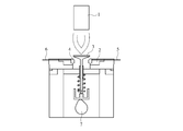
[1] 摩耗試験
得られたリング状焼結体をバルブシートに加工し、図1に示した単体摩耗試験機を用いて耐摩耗性を評価した。バルブシート4はシリンダヘッド相当材のバルブシートホルダ2に圧入して試験機にセットされ、摩耗試験は、バーナー1によりバルブ3及びバルブシート4を加熱しながら、カム7の回転に連動してバルブ3を上下させることによって行われる。なお、バルブシート4には熱電対5, 6を埋め込み、バルブシートの当たり面が所定の温度になるようにバーナー1の火力を調節する。バルブシート4はバルブ3によって繰り返し叩かれることにより摩耗し、その摩耗量は試験前後のバルブシート及びバルブの形状を測定することにより、当たり面の後退量として算出した。ここで、バルブはSUH合金(JIS規格:JIS G 4311)にステライト(登録商標)#12(Cr:29~31質量%、C:1.4~1.8質量%、W:8質量%、残部:Co)を盛金した上記バルブシートに適合するサイズのものを使用した。試験条件としては、温度250℃(バルブシート当たり面)、カム回転数2000 rpm、試験時間5時間とした。試験結果を、前述した焼結体の密度(相対密度)、HRC硬さとともに、表2に示す。 [1] Wear test The obtained ring-shaped sintered body was processed into a valve seat, and the wear resistance was evaluated using a single wear tester shown in FIG. The valve seat 4 is press-fitted into avalve seat holder 2 which is a cylinder head equivalent material and set in a testing machine. The wear test is performed in conjunction with the rotation of the cam 7 while the valve 3 and the valve seat 4 are heated by the burner 1. Done by moving 3 up and down. Thermocouples 5 and 6 are embedded in the valve seat 4, and the heating power of the burner 1 is adjusted so that the contact surface of the valve seat has a predetermined temperature. The valve seat 4 was worn by being repeatedly struck by the valve 3, and the amount of wear was calculated as the receding amount of the contact surface by measuring the shape of the valve seat and the valve before and after the test. Here, the valve is SUH alloy (JIS standard: JIS G 4311) and Stellite (registered trademark) # 12 (Cr: 29-31% by mass, C: 1.4-1.8% by mass, W: 8% by mass, balance: Co) A size suitable for the above valve seat was used. The test conditions were a temperature of 250 ° C. (surface per valve seat), a cam rotation speed of 2000 rpm, and a test time of 5 hours. The test results are shown in Table 2 together with the above-mentioned sintered body density (relative density) and HRC hardness.
得られたリング状焼結体をバルブシートに加工し、図1に示した単体摩耗試験機を用いて耐摩耗性を評価した。バルブシート4はシリンダヘッド相当材のバルブシートホルダ2に圧入して試験機にセットされ、摩耗試験は、バーナー1によりバルブ3及びバルブシート4を加熱しながら、カム7の回転に連動してバルブ3を上下させることによって行われる。なお、バルブシート4には熱電対5, 6を埋め込み、バルブシートの当たり面が所定の温度になるようにバーナー1の火力を調節する。バルブシート4はバルブ3によって繰り返し叩かれることにより摩耗し、その摩耗量は試験前後のバルブシート及びバルブの形状を測定することにより、当たり面の後退量として算出した。ここで、バルブはSUH合金(JIS規格:JIS G 4311)にステライト(登録商標)#12(Cr:29~31質量%、C:1.4~1.8質量%、W:8質量%、残部:Co)を盛金した上記バルブシートに適合するサイズのものを使用した。試験条件としては、温度250℃(バルブシート当たり面)、カム回転数2000 rpm、試験時間5時間とした。試験結果を、前述した焼結体の密度(相対密度)、HRC硬さとともに、表2に示す。 [1] Wear test The obtained ring-shaped sintered body was processed into a valve seat, and the wear resistance was evaluated using a single wear tester shown in FIG. The valve seat 4 is press-fitted into a

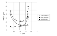
焼結体の密度は7.5~7.67 g/cm3、相対密度にして95.5~97.7%となり、非常に緻密な焼結体が得られている。また焼結体のロックウェル硬度HRCは24.5~36.5であった。これらはC量の増加とともに増加する傾向にあった。本発明の組成範囲では、Cは炭化物を形成して硬度を高めるだけでなく、焼結性も高めていることが明らかになった。図2はバルブシート摩耗量、バルブ摩耗量、及びそれらの合計摩耗量を、基地中のC%に対してプロットしたものである。バルブの摩耗量はC%が低いと極僅かであるが、C%が高くなると著しく多くなる。一方、バルブシートの摩耗量は、C%が低ければ多いが、C%が高くても一定の量より少なくなることはなくやや増加する傾向も示している。バルブとバルブシートの合計摩耗量という観点では、Cが1.2質量%より低くなれば急激に摩耗量が増加し、1.6質量%より高くなればやはり急激に摩耗量が増加する。Cの1.2~1.6質量%の数値範囲で、バルブとバルブシートの合計摩耗量が極めて低く抑えられるということが見出された。
The density of the sintered body is 7.5 to 7.67 g / cm 3 , and the relative density is 95.5 to 97.7%, and a very dense sintered body is obtained. The Rockwell hardness HRC of the sintered body was 24.5 to 36.5. These tended to increase with increasing C content. In the composition range of the present invention, it has become clear that C not only increases the hardness by forming carbides but also increases the sinterability. FIG. 2 is a plot of valve seat wear, valve wear, and their total wear against C% in the base. The amount of wear of the valve is negligible when C% is low, but increases significantly when C% is high. On the other hand, the amount of wear of the valve seat is large when C% is low, but even when C% is high, it shows a tendency to increase slightly without decreasing below a certain amount. In terms of the total amount of wear of the valve and the valve seat, the amount of wear increases rapidly when C is lower than 1.2% by mass, and the amount of wear increases abruptly when C is higher than 1.6% by mass. It was found that the total wear amount of the valve and the valve seat can be kept extremely low in the numerical range of 1.2 to 1.6% by mass of C.
比較例4の焼結体は、密度が7.16 g/cm3、相対密度にして90.8%と緻密化が進んでいなかったため、硬度も低く、バルブシートの自己摩耗量も多かった。Pの0.8質量%以上(FeP:焼結合金全体に対し約3.0質量%以上)の添加が緻密化に有効であることが見出された。
The sintered body of Comparative Example 4 had a density of 7.16 g / cm 3 and a relative density of 90.8%, which had not been densified. Therefore, the hardness was low and the amount of self-abrasion of the valve seat was large. It was found that the addition of 0.8 mass% or more of P (FeP: about 3.0 mass% or more with respect to the entire sintered alloy) is effective for densification.
実施例7
硬質粒子としてビッカース硬さがHv 980で平均粒径28μmのCr-W-Co-Fe合金を15質量%配合した以外は、実施例4と同様に混合、成形、焼結してリング状焼結体を作製した。ここで、使用したCr-W-Co-Fe合金は、質量%でCr:31.8%、W:22.0%、Co:8.4%、C:2.1%、残部:Fe及び不可避的不純物からなる組成を有していた。焼結体の密度及び硬度を測定し、摩耗試験も実施例4と同様に行った。基地組成並びに硬質粒子の種類及び混合比率を表3に、焼結体の密度及び硬度並びに摩耗試験の結果を表4に示す。 Example 7
Ring-shaped sintering by mixing, molding, and sintering in the same manner as in Example 4 except that 15% by mass of Cr-W-Co-Fe alloy having a Vickers hardness of Hv 980 and an average particle size of 28 μm was blended as hard particles The body was made. The Cr—W—Co—Fe alloy used here has a composition consisting of Cr: 31.8%, W: 22.0%, Co: 8.4%, C: 2.1%, the balance: Fe and inevitable impurities in mass%. Was. The density and hardness of the sintered body were measured, and the wear test was performed in the same manner as in Example 4. Table 3 shows the matrix composition, hard particle type and mixing ratio, and Table 4 shows the density and hardness of the sintered body and the results of the wear test.
実施例8
硬質粒子として実施例4で使用したFe-Mo-Si合金を10質量%と実施例7で使用したCr-W-Co-Fe合金を5質量%配合した以外は、実施例4と同様に混合、成形、焼結してリング状焼結体を作製した。焼結体の密度及び硬度を測定し、摩耗試験も実施例4と同様に行った。基地組成並びに硬質粒子の種類及び混合比率を表3に、焼結体の密度及び硬度並びに摩耗試験の結果を表4に実施例7の結果とともに示す。 Example 8
The same mixing as in Example 4 except that 10% by mass of the Fe—Mo—Si alloy used in Example 4 and 5% by mass of the Cr—W—Co—Fe alloy used in Example 7 were mixed as hard particles. A ring-shaped sintered body was produced by molding and sintering. The density and hardness of the sintered body were measured, and the wear test was performed in the same manner as in Example 4. Table 3 shows the matrix composition, hard particle type and mixing ratio, and Table 4 shows the density and hardness of the sintered body and the results of the abrasion test together with the results of Example 7.
実施例9
1120℃の真空雰囲気の代わりに、1120℃のN2+H2混合ガス雰囲気で焼成した以外は、実施例4と同様にリング状焼結体を作製した。焼結体の密度及び硬度を測定し、摩耗試験も実施例4と同様に行った。基地組成並びに硬質粒子の種類及び混合比率を表3に、焼結体の密度及び硬度並びに摩耗試験の結果を表4に実施例7及び8の結果とともに示す。N2+H2混合ガス雰囲気での焼成により、表面が窒化され、HRC 46.3の高硬度が得られた。 Example 9
Instead of a vacuum atmosphere at 1120 ° C., except firing at N 2 + H 2 mixed gas atmosphere of 1120 ° C., was prepared in the same manner as the ring-shaped sintered body as in Example 4. The density and hardness of the sintered body were measured, and the wear test was performed in the same manner as in Example 4. Table 3 shows the matrix composition, the type and mixing ratio of the hard particles, and Table 4 shows the density and hardness of the sintered body and the results of the wear test together with the results of Examples 7 and 8. The surface was nitrided by firing in a N 2 + H 2 mixed gas atmosphere, and a high hardness of HRC 46.3 was obtained.
比較例5
比較例5として金属間化合物の硬質粒子の代わりに平均粒径10μmのTiNを10質量%とした以外は、実施例4と同様にリング状焼結体を作製した。焼結体の密度及び硬度を測定し、摩耗試験も実施例4と同様に行った。基地組成並びに硬質粒子の種類及び混合比率を表3に、焼結体の密度及び硬度並びに摩耗試験の結果を表4に実施例7~9の結果とともに示す。比較例5の硬さの測定値は、TiNの高硬度(Hv 2000~2400)が焼結体の硬さを上げていることを示している。また、摩耗量はバルブシートもバルブも摩耗量が多い傾向にあった。なお、焼結体全体の組成成分を実施例1~9及び比較例1~5のデータとともに表5に示す。 Comparative Example 5
As Comparative Example 5, a ring-shaped sintered body was produced in the same manner as in Example 4, except that TiN having an average particle diameter of 10 μm was changed to 10% by mass instead of the hard particles of the intermetallic compound. The density and hardness of the sintered body were measured, and the wear test was performed in the same manner as in Example 4. Table 3 shows the matrix composition, the kind and mixing ratio of the hard particles, and Table 4 shows the density and hardness of the sintered body and the results of the abrasion test together with the results of Examples 7-9. The measured value of hardness in Comparative Example 5 indicates that the high hardness (Hv 2000-2400) of TiN increases the hardness of the sintered body. Further, the wear amount of both the valve seat and the valve tended to be large. The composition components of the entire sintered body are shown in Table 5 together with the data of Examples 1 to 9 and Comparative Examples 1 to 5.


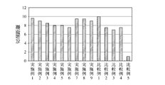
[2] 被削性試験
続いて、前述の実施例1~9及び比較例1~5の焼結体について被削性試験を行った。試験条件は汎用旋盤を用いた切削速度100 m/min、切り込み量0.1 mm、送り速度0.1 mm/revの乾式(切削液を使用しない)で、所謂トラバース方式の切削試験を行った。切削工具としてはCBNチップを使用し、被削性は逃げ面摩耗量が所定量となった時点の切削距離により評価した。結果を図3に示す。 [2] Machinability Test Subsequently, the machinability test was performed on the sintered bodies of Examples 1 to 9 and Comparative Examples 1 to 5 described above. The test conditions were a dry traverse method using a general-purpose lathe with a cutting speed of 100 m / min, a cutting depth of 0.1 mm, and a feed speed of 0.1 mm / rev (no cutting fluid used), and a so-called traverse type cutting test was performed. A CBN tip was used as the cutting tool, and the machinability was evaluated by the cutting distance when the flank wear amount reached a predetermined amount. The results are shown in FIG.
続いて、前述の実施例1~9及び比較例1~5の焼結体について被削性試験を行った。試験条件は汎用旋盤を用いた切削速度100 m/min、切り込み量0.1 mm、送り速度0.1 mm/revの乾式(切削液を使用しない)で、所謂トラバース方式の切削試験を行った。切削工具としてはCBNチップを使用し、被削性は逃げ面摩耗量が所定量となった時点の切削距離により評価した。結果を図3に示す。 [2] Machinability Test Subsequently, the machinability test was performed on the sintered bodies of Examples 1 to 9 and Comparative Examples 1 to 5 described above. The test conditions were a dry traverse method using a general-purpose lathe with a cutting speed of 100 m / min, a cutting depth of 0.1 mm, and a feed speed of 0.1 mm / rev (no cutting fluid used), and a so-called traverse type cutting test was performed. A CBN tip was used as the cutting tool, and the machinability was evaluated by the cutting distance when the flank wear amount reached a predetermined amount. The results are shown in FIG.
図3は、比較例5の切削距離を1とした相対比較を示している。硬質粒子がTiNの比較例5に比べ、金属間化合物を硬質粒子とした本発明は優れた被削性を示し、また鉄基焼結バルブシートのCが1.6質量%を超えると、被削性が低下する傾向にあった。
FIG. 3 shows a relative comparison in which the cutting distance of Comparative Example 5 is 1. Compared to Comparative Example 5 in which the hard particles are TiN, the present invention in which the intermetallic compound is a hard particle shows excellent machinability, and when C of the iron-based sintered valve seat exceeds 1.6% by mass, the machinability Tended to decrease.
FIG. 3 shows a relative comparison in which the cutting distance of Comparative Example 5 is 1. Compared to Comparative Example 5 in which the hard particles are TiN, the present invention in which the intermetallic compound is a hard particle shows excellent machinability, and when C of the iron-based sintered valve seat exceeds 1.6% by mass, the machinability Tended to decrease.
Claims (6)
- 基地中に、平均粒径5~200μm、ビッカース硬さHv 800~1200の金属間化合物からなる硬質粒子を体積%で5~14%分散させた鉄基焼結バルブシートであって、前記基地の組成がC、Si、Cr、Mo、V、P、並びに残部がFe及び不可避的不純物からなり、前記C及び前記Pは質量%で前記鉄基焼結バルブシートに対しC:1.2~1.6%、P:0.80~1.35%であることを特徴とする鉄基焼結バルブシート。 An iron-based sintered valve seat in which hard particles made of an intermetallic compound having an average particle size of 5 to 200 μm and a Vickers hardness of Hv 800 to 1200 are dispersed in a volume of 5 to 14% by volume. The composition is C, Si, Cr, Mo, V, P, and the balance consists of Fe and unavoidable impurities, and the C and P are in mass% with respect to the iron-based sintered valve seat C: 1.2 to 1.6%, P: An iron-based sintered valve seat characterized by 0.80 to 1.35%.
- 請求項1に記載の鉄基焼結バルブシートにおいて、前記基地の組成が質量%で、C:1.3~1.85%、Si:0.4~0.8%、Cr:10.0~13.0%、Mo:0.8~1.2%、V:1.7~2.2%、P:0.80~1.72%、並びに残部:Fe及び不可避的不純物からなるように配合した原料粉末を使用することを特徴とする鉄基焼結バルブシート。 The iron-based sintered valve seat according to claim 1, wherein the composition of the matrix is mass%, C: 1.3 to 1.85%, Si: 0.4 to 0.8%, Cr: 10.0 to 13.0%, Mo: 0.8 to 1.2% V: 1.7 to 2.2%, P: 0.80 to 1.72%, and balance: Fe-based sintered valve seat blended so as to be composed of Fe and inevitable impurities.
- 請求項1又は2に記載の鉄基焼結バルブシートにおいて、前記硬質粒子がFe-Mo-Si合金及び/又はCr-W-Co-Fe合金からなることを特徴とする鉄基焼結バルブシート。 The iron-based sintered valve seat according to claim 1 or 2, wherein the hard particles are made of a Fe-Mo-Si alloy and / or a Cr-W-Co-Fe alloy. .
- 請求項3に記載の鉄基焼結バルブシートにおいて、前記Fe-Mo-Si合金が質量%で、Mo:40~70%、Si:0.4~2.0%、C:0.1%以下、並びに残部:Fe及び不可避的不純物、前記Cr-W-Co-Fe合金が質量%で、Cr:27~33%、W:22~28%、Co:8~12%、並びに残部:Fe及び不可避的不純物からなることを特徴とする鉄基焼結バルブシート。 The iron-based sintered valve seat according to claim 3, wherein the Fe-Mo-Si alloy is mass%, Mo: 40-70%, Si: 0.4-2.0%, C: 0.1% or less, and the balance: Fe And inevitable impurities, the Cr-W-Co-Fe alloy is in mass%, Cr: 27-33%, W: 22-28%, Co: 8-12%, and the balance: Fe and inevitable impurities An iron-based sintered valve seat. *
- 請求項4に記載の鉄基焼結バルブシートにおいて、前記Si、Cr、Mo、及びVが質量%で鉄基焼結バルブシートに対しSi:0.5~0.9%、Cr:8.0~11.0%、Mo:5.0~10.0%、及びV:1.4~1.9%であることを特徴とする鉄基焼結バルブシート。 5. The iron-based sintered valve seat according to claim 4, wherein the Si, Cr, Mo, and V are in mass% with respect to the iron-based sintered valve seat, Si: 0.5 to 0.9%, Cr: 8.0 to 11.0%, Mo : Iron-based sintered valve seat characterized by 5.0 to 10.0% and V: 1.4 to 1.9%.
- 請求項1~5のいずれかに記載の鉄基焼結バルブシートにおいて、密度が7.5~7.8 g/cm3であることを特徴とする鉄基焼結バルブシート。 The iron-based sintered valve seat according to any one of claims 1 to 5, wherein the density is 7.5 to 7.8 g / cm 3 .
Priority Applications (3)
| Application Number | Priority Date | Filing Date | Title |
|---|---|---|---|
| CN201380035048.XA CN104428436B (en) | 2012-07-06 | 2013-07-03 | Iron-base sintered alloy valve seat |
| US14/412,910 US9359921B2 (en) | 2012-07-06 | 2013-07-03 | Sintered iron-based alloy valve seat |
| IN371DEN2015 IN2015DN00371A (en) | 2012-07-06 | 2013-07-03 |
Applications Claiming Priority (2)
| Application Number | Priority Date | Filing Date | Title |
|---|---|---|---|
| JP2012-152597 | 2012-07-06 | ||
| JP2012152597A JP5462325B2 (en) | 2012-07-06 | 2012-07-06 | Ferrous sintered alloy valve seat |
Publications (1)
| Publication Number | Publication Date |
|---|---|
| WO2014007278A1 true WO2014007278A1 (en) | 2014-01-09 |
Family
ID=49882030
Family Applications (1)
| Application Number | Title | Priority Date | Filing Date |
|---|---|---|---|
| PCT/JP2013/068228 WO2014007278A1 (en) | 2012-07-06 | 2013-07-03 | Valve seat made of iron-base sintered alloy |
Country Status (5)
| Country | Link |
|---|---|
| US (1) | US9359921B2 (en) |
| JP (1) | JP5462325B2 (en) |
| CN (1) | CN104428436B (en) |
| IN (1) | IN2015DN00371A (en) |
| WO (1) | WO2014007278A1 (en) |
Cited By (1)
| Publication number | Priority date | Publication date | Assignee | Title |
|---|---|---|---|---|
| WO2015141331A1 (en) * | 2014-03-19 | 2015-09-24 | 株式会社リケン | Valve seat constituted of iron-based sintered alloy |
Families Citing this family (19)
| Publication number | Priority date | Publication date | Assignee | Title |
|---|---|---|---|---|
| JP6508611B2 (en) * | 2015-03-30 | 2019-05-08 | 日立化成株式会社 | Sintered alloy and method of manufacturing the same |
| DE102015211623A1 (en) * | 2015-06-23 | 2016-12-29 | Mahle International Gmbh | Method for producing a valve seat ring |
| US10391557B2 (en) | 2016-05-26 | 2019-08-27 | Kennametal Inc. | Cladded articles and applications thereof |
| CN107838413B (en) * | 2017-09-30 | 2021-03-16 | 东风商用车有限公司 | Heavy-duty engine powder metallurgy valve seat material and preparation method thereof |
| US10344757B1 (en) | 2018-01-19 | 2019-07-09 | Kennametal Inc. | Valve seats and valve assemblies for fluid end applications |
| US11566718B2 (en) | 2018-08-31 | 2023-01-31 | Kennametal Inc. | Valves, valve assemblies and applications thereof |
| US11236834B2 (en) * | 2019-03-08 | 2022-02-01 | Applied Materials, Inc. | Diaphragm valves and methods of operating same |
| US11353117B1 (en) | 2020-01-17 | 2022-06-07 | Vulcan Industrial Holdings, LLC | Valve seat insert system and method |
| US11421680B1 (en) | 2020-06-30 | 2022-08-23 | Vulcan Industrial Holdings, LLC | Packing bore wear sleeve retainer system |
| US11421679B1 (en) | 2020-06-30 | 2022-08-23 | Vulcan Industrial Holdings, LLC | Packing assembly with threaded sleeve for interaction with an installation tool |
| US11384756B1 (en) | 2020-08-19 | 2022-07-12 | Vulcan Industrial Holdings, LLC | Composite valve seat system and method |
| USD986928S1 (en) | 2020-08-21 | 2023-05-23 | Vulcan Industrial Holdings, LLC | Fluid end for a pumping system |
| USD997992S1 (en) | 2020-08-21 | 2023-09-05 | Vulcan Industrial Holdings, LLC | Fluid end for a pumping system |
| USD980876S1 (en) | 2020-08-21 | 2023-03-14 | Vulcan Industrial Holdings, LLC | Fluid end for a pumping system |
| JP2022050275A (en) * | 2020-09-17 | 2022-03-30 | 株式会社リケン | Sintered valve seat |
| US11391374B1 (en) | 2021-01-14 | 2022-07-19 | Vulcan Industrial Holdings, LLC | Dual ring stuffing box |
| US11434900B1 (en) * | 2022-04-25 | 2022-09-06 | Vulcan Industrial Holdings, LLC | Spring controlling valve |
| US11920684B1 (en) | 2022-05-17 | 2024-03-05 | Vulcan Industrial Holdings, LLC | Mechanically or hybrid mounted valve seat |
| CN117120655A (en) * | 2022-12-09 | 2023-11-24 | 帝伯爱尔株式会社 | Iron-based sintered alloy valve seat |
Citations (5)
| Publication number | Priority date | Publication date | Assignee | Title |
|---|---|---|---|---|
| JPH06101429A (en) * | 1992-09-22 | 1994-04-12 | Mitsubishi Materials Corp | Lead impregnated iron system sintered alloy made valve seat for internal combustion engine |
| JPH06306409A (en) * | 1993-04-22 | 1994-11-01 | Mitsubishi Materials Corp | Valve guide member made of iron-base sintered alloy excellent in wear resistance |
| JP2002129296A (en) * | 2000-10-27 | 2002-05-09 | Nippon Piston Ring Co Ltd | Iron-base sintered alloy material for valve seat, and valve seat made of iron-base sintered alloy |
| JP3784003B2 (en) * | 2001-01-31 | 2006-06-07 | 日立粉末冶金株式会社 | Turbo parts for turbochargers |
| WO2011105338A1 (en) * | 2010-02-23 | 2011-09-01 | 株式会社リケン | Valve seat |
Family Cites Families (15)
| Publication number | Priority date | Publication date | Assignee | Title |
|---|---|---|---|---|
| US4129444A (en) * | 1973-01-15 | 1978-12-12 | Cabot Corporation | Power metallurgy compacts and products of high performance alloys |
| JPS5830361B2 (en) * | 1979-02-26 | 1983-06-29 | 日本ピストンリング株式会社 | Method for manufacturing wear-resistant parts for internal combustion engines |
| JPS55145151A (en) * | 1979-04-26 | 1980-11-12 | Nippon Piston Ring Co Ltd | Wear resistant sintered alloy material for internal combustion engine |
| JPS6119762A (en) | 1984-07-06 | 1986-01-28 | Riken Corp | Abrasion resistant sintered alloy |
| JPS6196058A (en) * | 1984-10-15 | 1986-05-14 | Toyota Motor Corp | Control valve sliding member and its production |
| JP2506333B2 (en) * | 1986-03-12 | 1996-06-12 | 日産自動車株式会社 | Abrasion resistant iron-based sintered alloy |
| JP2777373B2 (en) * | 1988-06-28 | 1998-07-16 | 日産自動車株式会社 | Heat- and wear-resistant iron-based sintered alloy |
| JPH05117703A (en) * | 1991-09-05 | 1993-05-14 | Kawasaki Steel Corp | Iron-base powder composition for powder metallurgy, its production and production of iron-base sintering material |
| US5507257A (en) | 1993-04-22 | 1996-04-16 | Mitsubishi Materials Corporation | Value guide member formed of Fe-based sintered alloy having excellent wear and abrasion resistance |
| JP3343313B2 (en) * | 1995-06-30 | 2002-11-11 | 株式会社フジキン | Diaphragm valve |
| JP3952344B2 (en) * | 1998-12-28 | 2007-08-01 | 日本ピストンリング株式会社 | Wear-resistant iron-based sintered alloy material for valve seat and valve seat made of iron-based sintered alloy |
| EP1391529B1 (en) * | 2002-08-16 | 2008-10-01 | Alloy Technology Solutions, Inc. | Wear and corrosion resistant austenitic iron base alloy |
| WO2004059474A2 (en) * | 2002-12-20 | 2004-07-15 | Applied Materials, Inc. | Micromachined intergrated fluid delivery system |
| JP4423254B2 (en) * | 2005-12-02 | 2010-03-03 | 株式会社神戸製鋼所 | High strength spring steel wire with excellent coiling and hydrogen embrittlement resistance |
| US20080146467A1 (en) * | 2006-01-26 | 2008-06-19 | Takemori Takayama | Sintered Material, Ferrous Sintered Sliding Material, Producing Method of the Same, Sliding Member, Producing Method of the Same and Coupling Device |
-
2012
- 2012-07-06 JP JP2012152597A patent/JP5462325B2/en not_active Expired - Fee Related
-
2013
- 2013-07-03 US US14/412,910 patent/US9359921B2/en not_active Expired - Fee Related
- 2013-07-03 WO PCT/JP2013/068228 patent/WO2014007278A1/en active Application Filing
- 2013-07-03 IN IN371DEN2015 patent/IN2015DN00371A/en unknown
- 2013-07-03 CN CN201380035048.XA patent/CN104428436B/en not_active Expired - Fee Related
Patent Citations (5)
| Publication number | Priority date | Publication date | Assignee | Title |
|---|---|---|---|---|
| JPH06101429A (en) * | 1992-09-22 | 1994-04-12 | Mitsubishi Materials Corp | Lead impregnated iron system sintered alloy made valve seat for internal combustion engine |
| JPH06306409A (en) * | 1993-04-22 | 1994-11-01 | Mitsubishi Materials Corp | Valve guide member made of iron-base sintered alloy excellent in wear resistance |
| JP2002129296A (en) * | 2000-10-27 | 2002-05-09 | Nippon Piston Ring Co Ltd | Iron-base sintered alloy material for valve seat, and valve seat made of iron-base sintered alloy |
| JP3784003B2 (en) * | 2001-01-31 | 2006-06-07 | 日立粉末冶金株式会社 | Turbo parts for turbochargers |
| WO2011105338A1 (en) * | 2010-02-23 | 2011-09-01 | 株式会社リケン | Valve seat |
Cited By (3)
| Publication number | Priority date | Publication date | Assignee | Title |
|---|---|---|---|---|
| WO2015141331A1 (en) * | 2014-03-19 | 2015-09-24 | 株式会社リケン | Valve seat constituted of iron-based sintered alloy |
| JP2015178650A (en) * | 2014-03-19 | 2015-10-08 | 株式会社リケン | Iron-based sinter alloy valve sheet |
| US10233793B2 (en) | 2014-03-19 | 2019-03-19 | Kabushiki Kaisha Riken | Valve seat of sintered iron-based alloy |
Also Published As
| Publication number | Publication date |
|---|---|
| IN2015DN00371A (en) | 2015-06-12 |
| CN104428436B (en) | 2016-10-26 |
| JP2014015645A (en) | 2014-01-30 |
| US20150152753A1 (en) | 2015-06-04 |
| CN104428436A (en) | 2015-03-18 |
| JP5462325B2 (en) | 2014-04-02 |
| US9359921B2 (en) | 2016-06-07 |
Similar Documents
| Publication | Publication Date | Title |
|---|---|---|
| JP5462325B2 (en) | Ferrous sintered alloy valve seat | |
| US9212572B2 (en) | Sintered valve guide and production method therefor | |
| JP3926320B2 (en) | Iron-based sintered alloy valve seat and method for manufacturing the same | |
| JP4584158B2 (en) | Valve seat material made of iron-based sintered alloy for internal combustion engines | |
| US9803268B2 (en) | Iron-base sintered alloy material for valve seat insert and method for manufacturing the same | |
| JP5887374B2 (en) | Ferrous sintered alloy valve seat | |
| JP5649830B2 (en) | Valve seat | |
| CN100422376C (en) | Iron-base sintered alloy valve holder materials for internal combustion engine | |
| WO2012099239A1 (en) | Iron-based sintered alloy valve seat | |
| JP7188434B2 (en) | Sintered valve guide and its manufacturing method | |
| JP6431012B2 (en) | Method for producing wear-resistant iron-based sintered alloy and wear-resistant iron-based sintered alloy | |
| JP6392796B2 (en) | Method for producing wear-resistant iron-based sintered alloy, compact for sintered alloy, and wear-resistant iron-based sintered alloy | |
| JP6392530B2 (en) | Ferrous sintered alloy valve seat | |
| JP6528899B2 (en) | Method of manufacturing mixed powder and sintered body for powder metallurgy | |
| JP6352959B2 (en) | Method for producing wear-resistant iron-based sintered alloy, compact for sintered alloy, and wear-resistant iron-based sintered alloy | |
| JPH09209095A (en) | Iron-base sintered alloy excellent in wear resistance | |
| JP6077499B2 (en) | Sintered alloy molded body, wear-resistant iron-based sintered alloy, and method for producing the same | |
| JP6842345B2 (en) | Abrasion-resistant iron-based sintered alloy manufacturing method | |
| JP2013173961A (en) | Valve seat made from iron-based sintered alloy | |
| JPH06158217A (en) | Valve guide member made of fe-based sintered alloy excellent in wear resistance | |
| JPH03134139A (en) | Iron-base sintered alloy for valve seat | |
| JP2006037138A (en) | Valve seat made of iron based sintered alloy | |
| JPH06158242A (en) | Valve guide member made of fe base sintered alloy excellent in wear resistance |
Legal Events
| Date | Code | Title | Description |
|---|---|---|---|
| 121 | Ep: the epo has been informed by wipo that ep was designated in this application |
Ref document number: 13813178 Country of ref document: EP Kind code of ref document: A1 |
|
| WWE | Wipo information: entry into national phase |
Ref document number: 14412910 Country of ref document: US |
|
| NENP | Non-entry into the national phase |
Ref country code: DE |
|
| 122 | Ep: pct application non-entry in european phase |
Ref document number: 13813178 Country of ref document: EP Kind code of ref document: A1 |