WO2014007031A1 - 車載電源制御装置 - Google Patents
車載電源制御装置 Download PDFInfo
- Publication number
- WO2014007031A1 WO2014007031A1 PCT/JP2013/066135 JP2013066135W WO2014007031A1 WO 2014007031 A1 WO2014007031 A1 WO 2014007031A1 JP 2013066135 W JP2013066135 W JP 2013066135W WO 2014007031 A1 WO2014007031 A1 WO 2014007031A1
- Authority
- WO
- WIPO (PCT)
- Prior art keywords
- storage battery
- vehicle
- voltage
- switching element
- lower limit
- Prior art date
- Legal status (The legal status is an assumption and is not a legal conclusion. Google has not performed a legal analysis and makes no representation as to the accuracy of the status listed.)
- Ceased
Links
Images





Classifications
-
- B—PERFORMING OPERATIONS; TRANSPORTING
- B60—VEHICLES IN GENERAL
- B60R—VEHICLES, VEHICLE FITTINGS, OR VEHICLE PARTS, NOT OTHERWISE PROVIDED FOR
- B60R16/00—Electric or fluid circuits specially adapted for vehicles and not otherwise provided for; Arrangement of elements of electric or fluid circuits specially adapted for vehicles and not otherwise provided for
- B60R16/02—Electric or fluid circuits specially adapted for vehicles and not otherwise provided for; Arrangement of elements of electric or fluid circuits specially adapted for vehicles and not otherwise provided for electric constitutive elements
- B60R16/03—Electric or fluid circuits specially adapted for vehicles and not otherwise provided for; Arrangement of elements of electric or fluid circuits specially adapted for vehicles and not otherwise provided for electric constitutive elements for supply of electrical power to vehicle subsystems or for
- B60R16/033—Electric or fluid circuits specially adapted for vehicles and not otherwise provided for; Arrangement of elements of electric or fluid circuits specially adapted for vehicles and not otherwise provided for electric constitutive elements for supply of electrical power to vehicle subsystems or for characterised by the use of electrical cells or batteries
Definitions
- the present invention relates to an in-vehicle power supply control device.
- An electric motor represented by a starter motor is used for starting an automobile engine, and the electric motor is driven by electric power from a storage battery mounted on the automobile.
- the starter motor starts the engine, momentary large electric power is required, and the storage battery as the engine starting power source is required to be discharged by a large current.
- Patent Document 1 shows an example in which a capacitor is used as a power source for starting an engine.
- Patent Document 1 discloses a technique for receiving power supply from another storage battery that does not supply starting power and charging the capacitor to a high voltage for an upcoming engine start in order to further improve engine startability by the capacitor. Is disclosed. However, if the state in which electric power is always stored in the capacitor is maintained, there is a problem that the electric energy that can be recovered during regeneration is greatly reduced.
- the on-vehicle power supply control device is mounted on a vehicle, and is mounted on the vehicle and includes a first storage battery that supplies power to a starter motor that transmits torque necessary for starting the engine to the engine.
- the first switching element and the first switching element are disposed between the first storage battery and the electric load between the second storage battery that supplies power to the electric load including the machinery.
- a control circuit that performs control to close both the first contact of the first switching element and the second contact of the second switching element, when the accelerator pedal of the vehicle is not depressed and the brake pedal of the vehicle is depressed
- the control circuit opens the first contact point of the first switching element and the second contact point of the second switching element with respect to the power accommodation circuit so that the electric power generated by the alternator is charged in the first storage battery. Is controlled to close.
- the utilization efficiency of the in-vehicle storage battery is improved.
- the connection configuration of the in-vehicle power supply control device and the peripheral device in one embodiment of the present invention will be described with reference to FIG.
- the on-vehicle power supply control device and peripheral devices are included in the vehicle 100.
- the in-vehicle power supply control device includes a controller 115 and a power interchange circuit 109
- the peripheral device includes devices other than the controller 115 and the power interchange circuit 109.
- the vehicle 100 includes an alternator 103 that is a generator that is rotationally driven by a belt 102 that transmits the driving force of the engine 101.
- a starter motor 104 which is a starter.
- a transmission 105 and a differential 106 are connected to the engine 101.
- Axle 107 drives wheels 108.
- the electric power generated by the alternator 103 is distributed to the first storage battery 110, the second storage battery 111, and the in-vehicle electric load 112 through the power interchange circuit 109.
- Charge state monitoring devices 113 and 114 are assembled to the first storage battery 110 and the second storage battery 111, respectively.
- the charging state monitoring devices 113 and 114 monitor the charging state of the first storage battery 110 and the second storage battery 111, respectively, and transmit the diagnosis result of the charging state to the controller 115.
- the accelerator pedal depression amount detection device 116 that detects the depression amount of the accelerator pedal 121
- the brake pedal depression amount detection device 117 that detects the depression amount of the brake pedal 122 are similarly sent to the controller 115. Send the amount detection result.
- the vehicle speed detection device 118 measures the vehicle speed of the automobile and transmits the measurement result of the vehicle speed to the controller 115.
- the controller 115 transmits a control signal to the alternator 103, the starter motor 104, and the power interchange device 109 based on information such as the diagnosis result, the detection result, and the measurement result obtained from each of the above-described devices, whereby the alternator 103, the starter.
- the motor 104 and the power interchange device 109 are controlled.
- the controller 115 includes a CPU that executes programs and arithmetic processing, a ROM that stores programs executed by the CPU, a RAM that temporarily stores information, an input / output port that is used to transmit and receive information, and the like.
- the information temporarily stored in the RAM includes a calculation result by the CPU of the controller 115 and a diagnosis result, a detection result, and a measurement result transmitted to the controller 115 by each of the devices described above.
- the first storage battery 110 supplies power to the starter motor 104, and the second storage battery 111 supplies power to the in-vehicle electric load 112 including auxiliary devices in the vehicle 100.
- the first storage battery 110 is preferably an assembled battery including at least one of an electric double layer capacitor and an asymmetric capacitor.
- the electric double layer capacitor may be a storage battery using an electric double layer, which is a physical phenomenon that occurs at the electrode interface in the battery. Carbon materials such as activated carbon and carbon nanotubes, metals, and the like are suitably used as electrodes. An aqueous solution, an organic solvent, or the like is filled between the electrodes.
- the asymmetric capacitor may be a storage battery having, as one electrode, an electrode to which the above-described electric double layer is applied, and having the other electrode as an intercalation type electrode or a dissolution precipitation type electrode.
- a lithium ion capacitor can be suitably used as the asymmetric capacitor.
- the second storage battery 111 is preferably a reserve storage battery or a rocking chair storage battery.
- the reserve type storage battery is a storage battery that can be charged and discharged by exchanging charges mainly by dissolution and precipitation reaction of metal.
- a lead acid storage battery can be suitably used.
- the rocking chair type storage battery may be a storage battery in which an intercalation type electrode is used as the positive electrode and the negative electrode, and the charge is exchanged by reciprocating between the positive electrode and the negative electrode by charging and discharging.
- Examples of the rocking chair type storage battery include a lithium ion secondary battery and a nickel hydride secondary battery.
- the first storage battery 110 and the second storage battery 111 are configured by connecting unit cells of minimum configuration in series and in parallel, respectively.
- an assembled battery combining a plurality of types of storage batteries such as a combination of a lithium ion capacitor and an electric double layer capacitor, may be used.
- an assembled battery in which a plurality of types of storage batteries are combined may be used.
- the first storage battery 110 is an assembled battery including at least one of an electric double layer capacitor and an asymmetric capacitor
- the second storage battery 111 is an assembled battery including at least one of a reserve storage battery and a rocking chair storage battery. If it is. By doing in this way, the 1st storage battery 110 can be discharged by an instantaneous large current required when the starter motor starts the engine, and can be rapidly charged. Battery life can be extended.
- the value of the quotient obtained by dividing the battery capacity of the second storage battery 111 by the battery capacity of the first storage battery 110 is 10 or more and 200 or less.
- the first storage battery 110 is preferentially charged over the second battery 111 in the charging mode (1).
- the battery capacity of the first storage battery 110 is smaller than the battery capacity of the second storage battery 111.
- the time required for preferential charging of the first storage battery 110 in the charging mode (1) is suppressed, and the possibility that the second storage battery 111 is not sufficiently charged during regeneration due to deceleration of the vehicle speed is suppressed. Since the time required for preferential charging of the first storage battery 110 is reduced, it is not necessary to mount a large amount of the first storage battery 110, and an in-vehicle power supply can be provided at low cost.
- the battery capacity of the first storage battery 110 is not too small. There is a high possibility that the engine 101 can be started using only the power supplied from the single storage battery 110, and the reduction in the number of idling stops can be suppressed to reduce fuel consumption. That is, if the value of the quotient obtained by dividing the battery capacity of the second storage battery 111 by the battery capacity of the first storage battery 110 is 10 or more and 200 or less, good power distribution is possible. It is possible to provide an in-vehicle power source at low cost because it is not necessary to mount the first storage battery 110 on the vehicle 100 in large quantities.
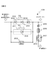
- FIG. 2 shows an example of the configuration of the power accommodation circuit 109.
- the power accommodation circuit 109 includes at least a first switching element 202 that enables a short circuit between the positive terminal of the first storage battery 110 and the positive terminal of the second storage battery 111, and the first storage battery 110 with respect to the power accommodation circuit 109.
- a second switching element 203 that can be electrically connected or disconnected.
- the first switching element 202 is disposed between the first storage battery 110 and the second storage battery 111 and between the first storage battery 110 and the in-vehicle electric load 112.
- the second switching element 203 is disposed between the first switching element 202 and the first storage battery 110 and between the alternator 103 and the first storage battery 110.
- the power interchange circuit 109 preferably further includes a first rectifier element 201 that limits the voltage or current in the direction D ⁇ b> 1 from the second storage battery 111 toward the first storage battery 110.
- the first rectifying element 201 is disposed in parallel with the first switching element 202 between the second switching element 203, the second storage battery 111, and the in-vehicle electric load 112.
- the power interchange circuit 109 further includes a second rectifying element 200 that limits the voltage or current in the direction D2 from the first storage battery 110 toward the second storage battery 111.
- the second rectifying element 200 is arranged in parallel with the first switching element 202 and the first rectifying element 201 between the second switching element 203 and the second storage battery 111 and the in-vehicle electric load 112.
- Each of the first rectifying element 201 and the second rectifying element 200 can be configured by connecting one or a plurality of diodes 204 in series as shown in FIG. Since one forward drop voltage of the diode 204 is approximately 0.5 V to 1.5 V, the voltage control by the first rectifier element 201 and the voltage control by the second rectifier element 200 are arbitrary and depending on the number of diodes 204 connected in series. It can be suitably provided.
- FIG. 2 shows a second rectifier element 200 configured by connecting three diodes 204 in series and a first rectifier element 200 configured by one diode 204.
- the number of diodes 204 to be connected is not particularly limited to the example shown in FIG. As each of the first rectifying element 201 and the second rectifying element 200, an arbitrary and suitable number of diodes 204 can be used.
- the first rectifying element 201 and the second rectifying element 200 are voltage-controlled rectifying elements using a diode 204.
- Each of the first rectifying element 201 and the second rectifying element 200 may be a current control type rectifying element using a switching element.
- a current control type rectifying element it is preferable to use a semiconductor switch such as an insulated gate bipolar transistor (Insulated Gate Bipolar Transistor, IGBT), a thyristor, a MOS-FET (Metal Oxide Semiconductor-Field Effect Transistor), or the like.
- a magnet switch or a semiconductor relay may be used as the first switching element 202 and the second switching element 203, respectively.
- a semiconductor switch is used as the first switching element 202
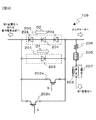
- forward current control or reverse current control may be performed depending on the arrangement direction of the semiconductor switch in the power interchange circuit 109. Therefore, as shown in FIG. 3, the switching elements 202a and 202b arranged in parallel with the first rectifying element 201 and the second rectifying element 200 are controlled by being arranged in parallel in mutually opposite arrangement directions. It is also possible to obtain a target characteristic considering both directions of current. Note that the switching elements 202 a and 202 b constitute the first switching element 202.
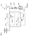
- the voltage-controlled or current-controlled first rectifying element 201 and second rectifying element 200 may also serve as the first switching element 202 shown in FIG. As shown in FIG. 4, the circuit can be simplified because the first rectifying element 201 and the second rectifying element 200 also function as the switching elements 202a and 202b, respectively, by a current-controlled rectifying element. Note that the switching elements 202 a and 202 b that are semiconductor switches constitute the first switching element 202. In such a case, the controller 115 compares the battery voltage measured by the charge state monitoring devices 113 and 114. The controller 115 controls the first rectifying element 201 and the second rectifying element 200 so that the battery voltage difference measured by the charge state monitoring devices 113 and 114 becomes a predetermined value. For example, the value of the current flowing through the power interchange circuit 109 can be adjusted by changing the duty ratio when the pulse signal is output from the controller 115. Note that the duty ratio is the ratio of the pulse rise time to one pulse period.
- a large reactance 205 as shown in FIG. 3 may be inserted in the vicinity of the second switching element 203 in order to mitigate steep power input, a resistor 206 may be included, and a snubber circuit may be included. 207 may be mounted in parallel with the second switching element 203. Any circuit element suitable for protecting such a circuit may be mounted on the circuit.
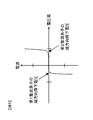
- FIGS When voltage-controlled rectifiers are used for the first rectifier element 201 and the second rectifier element 200, the current characteristics with respect to the voltage difference between both ends of the first rectifier element 201 and the second rectifier element 200 are shown in FIGS. It is shown in FIG.
- the current characteristics with respect to the voltage difference between both ends of the first rectifying element 201 and the second rectifying element 200 are shown in FIG. 5 when the contact of the first switching element 202 is open, and the contact of the first switching element 202 is closed. 6 is shown in FIG. 5 and 6, the voltage difference between both ends of the first rectifying element 201 and the second rectifying element 200 flows in the direction D2 with reference to the second storage battery 111 side corresponding to one of the both ends.
- the current has a positive value and the current flowing in the direction D1 has a negative value.
- the first switching element 202 is not driven by the controller 115, that is, when the contact of the first switching element 202 is open, as shown in FIG. 5, between the first storage battery 110 and the second storage battery 111, Since current does not flow until the forward voltage drop of each of the first rectifying element 201 and the second rectifying element 200 is applied, the voltage difference between both ends of the first rectifying element 201 and the second rectifying element 200 is maintained. That is, the voltage difference between the first storage battery 110 and the second storage battery 111 is maintained.
- the controller 115 drives the first switching element 202 to close the contact point of the first switching element 202, so that a current can flow regardless of the voltage difference between both ends of the first rectifying element 201 and the second rectifying element 200. It becomes like this. That is, regardless of the forward voltage drop of each of the first rectifying element 201 and the second rectifying element 200, the first storage battery 110 and the second storage battery 111 are preferentially discharged from a higher voltage battery, It becomes possible to charge the other battery having a low voltage with the discharge power of one of the first storage battery 110 and the second storage battery 111.
- first rectifier element 201 and the second rectifier element 200 only one of a voltage-controlled rectifier element and a current-controlled rectifier element may be used, or the first rectifier element 201 and the second rectifier element 200 may be used.
- a voltage-controlled rectifier element may be used for one of the elements 200 and a current-controlled rectifier element may be used for the other.
- the first storage battery 110 is an assembled battery including n1 single cells connected in series, and each of the n1 single battery cells has a voltage V12 when fully discharged and a voltage V12 greater than the voltage V11 when fully charged. Become. Therefore, the minimum discharge lower limit voltage VL of the first storage battery 110 is equal to n1 times the voltage V11 of each single battery cell, and the charge upper limit voltage VU larger than the minimum discharge lower limit voltage VL of the first storage battery 110 is the voltage of each single battery cell. Equal to n1 times V12.
- the second storage battery 111 is an assembled battery including n2 single battery cells connected in series, and the rated voltage C of the second storage battery 111 is equal to n2 times the rated voltage C0 of each single battery cell.
- the charging upper limit voltage Vu of the second storage battery 111 is larger than the rated voltage C and smaller than the charging upper limit voltage VU of the first storage battery 110.
- the minimum discharge lower limit voltage Vl of the second storage battery 111 is preferably smaller than the rated voltage C and larger than the minimum discharge lower limit voltage VL of the first storage battery 110. That is, it is preferable that the relationship VL ⁇ Vl ⁇ Vu ⁇ VU is established.
- the first rectifying element 201 included in the power interchange circuit 109 includes, for example, n3 diodes 204 connected in series, and the forward voltage drop V31 of the first rectifying element 201 is the forward voltage drop of each diode 204. Equal to n3 times V40.
- the second rectifying element 200 included in the power interchange circuit 109 includes, for example, n4 diodes 204 connected in series, and the forward voltage drop V32 of the second rectifying element 200 is the forward voltage drop of each diode 204. Equal to n4 times V40. At this time, it is preferable that 0 ⁇ V31 ⁇ V32 and VL ⁇ C ⁇ V31 ⁇ C ⁇ C + V32 ⁇ VU.
- the first storage battery 110 can be used for charging and discharging in the voltage range from C ⁇ V31 to C + V32. Become.
- the relationship of (VU ⁇ VL) ⁇ 2 + VL ⁇ C is established. That is, the rated voltage C of the second storage battery 111 is lower than the upper limit charging voltage VU of the first storage battery 110, higher than the lowest discharge lower limit voltage VL of the first storage battery 110, and lower than the upper limit charging voltage VU of the first storage battery 110. It is preferable that the sum of the quotient (VU ⁇ VL) / 2 obtained by dividing the difference obtained by subtracting the discharge lower limit voltage VL by 2 and the minimum discharge lower limit voltage VL of the first storage battery 110 is equal to or less.
- the first storage battery 110 that is a lithium ion capacitor is suitable for input / output of large power compared to the second storage battery 111 that is a lead acid storage battery, for example, and therefore VL ⁇ C ⁇ VU and (VU ⁇ VL) ⁇ When the relationship of 2 + VL ⁇ C is established, the utilization rate of the first storage battery 110 is improved.
- the charging voltage and the battery capacity are approximately proportional to each other, and the voltage obtained as a result of the calculation of (VU ⁇ VL) ⁇ 2 + VL is the battery capacity of the lithium ion capacitor.
- the voltage corresponds to approximately 50% of the voltage range in which charging / discharging is possible. If the configuration of the first storage battery 110 satisfies the relationship of (VU ⁇ VL) ⁇ 2 + VL ⁇ C, at least 50% or more of the power that can be stored and consumed by the first storage battery 110 will be described later.
- the “V. interchange mode (1)” the first storage battery 110 can be discharged to the second storage battery 111, or the first storage battery 110 can be supplied to the in-vehicle electric load 112. is there. That is, the utilization factor of the first storage battery 110 can be increased.
- the charging upper limit voltage Vu of the second storage battery 111 13.8 [V]
- the forward drop voltage V40 of the diode 204 included in the first rectifying element 201 and the second rectifying element 200 0.6 [V]
- One diode 204 included in one rectifying element 201 n3 2 the number
- FIG. 7 shows a power supply form at the time of normal engine start by a movement of current.
- the controller 115 controls the power interchange circuit 109 so that the contact of the second switching element 203 is opened.
- the first power supply system including the first storage battery 110 and the second power supply system including the second storage battery 111 are electrically disconnected. Since the first power supply system is disconnected from the second power supply system in this manner, the first storage battery 110 discharges a large amount of power necessary for supplying power to the starter motor 104 when the engine 101 is started. The engine can be started without interfering with the second power supply system.
- the second storage battery 111 does not need to discharge a large amount of power, voltage fluctuations associated with engine startup do not occur in the second storage battery 111, and power is stably supplied to the in-vehicle electric load 112 by the second storage battery 111. Deterioration of the second storage battery 111 due to rapid discharge is suppressed.
- FIG. 8 shows the power supply mode at the time of engine start in the safe mode by the movement of current. It is assumed that the charging voltage V1 of the first storage battery 110 is not sufficiently high. In such a case, the controller 115 controls the power interchange circuit 109 so that the contact of the second switching element 203 is closed. As a result, electrical connection between the first power supply system and the second power supply system is ensured. In this case, until the voltage difference exceeding the forward drop voltage V31 of the first rectifying element 201 is generated between the first storage battery 110 and the second storage battery 111, power is supplied to the starter motor 104 only by the first storage battery 110. Supplied.
- the charging voltage V1 of the first storage battery 110 When the charging voltage V1 of the first storage battery 110 further decreases, the voltage difference between the first storage battery 110 and the second storage battery 111 exceeds the forward voltage drop V31 of the first rectifying element 201. In addition to the discharge for supplying power to the electric load 112, the discharge for supplying power to the starter motor 104 is started. Thereby, even when the charging voltage V1 of the 1st storage battery 110 should fall by any chance, the engine 101 can be started reliably.
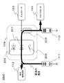
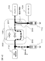
- FIG. 9 shows the power distribution mode when the vehicle speed is decelerated by the movement of current because the accelerator pedal 121 of the vehicle 100 is not depressed and the brake pedal 122 is depressed. At this time, electric power is generated by the alternator 103.
- the controller 115 controls the power interchange circuit 109 so that the contact of the first switching element 202 is opened and the contact of the second switching element 203 is closed. By doing so, the power generated by the alternator 103 is preferentially charged to the first storage battery 110 first.
- the first storage battery 110 When the charging of the first storage battery 110 progresses and the voltage difference between the first storage battery 110 and the second storage battery 111 exceeds the forward voltage drop V32 of the second rectifying element 200, it continues through the second switching element 203.
- the electric power generated by the alternator 103 is charged in the first storage battery 110, and the electric power generated by the alternator 103 is charged in the second storage battery 111 through the second rectifying element 200. That is, by providing the forward drop voltage V32 of the second rectifier element 200, the first storage battery 110 can be preferentially charged when the voltage of the first storage battery 110 is small.
- the voltage of the first storage battery 110 when the second rectifying element 200 is operated is automatically adjusted according to the charging voltage of the second storage battery 111, so the charging voltage of the second storage battery 111 is extremely reduced. It is possible to prevent the maintained state from being maintained.
- the electric power generated by the alternator 103 may be charged to the second storage battery 111 and supplied to the in-vehicle electric load 112 through the second rectifying element 200.
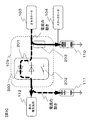
- FIG. 10 shows a charging mode for charging only the second storage battery 111 when the vehicle speed is decelerated in the inertial running state or the low speed running because the accelerator pedal 121 of the vehicle 100 is not depressed and the brake pedal 122 is hardly depressed. Is shown by the movement of the current.
- the controller 115 controls the power interchange circuit 109 so that the contact of the second switching element 203 is opened. Thereby, the electrical connection between the first power supply system and the second power supply system is disconnected.
- the controller 115 controls the power interchange circuit 109 so that the contact point of the first switching element 202 is closed, so that a charging current flows from the alternator 103 to the second storage battery 111 without passing through the second rectifying element 200. It becomes possible. Therefore, it is possible to prevent a voltage drop and a current loss due to the charging current flowing through the second rectifying element 200, and to charge the second storage battery 111 with a small loss.
- the opening / closing states of the first switching element 202 and the second switching element 203 are also the same state. Become.
- the engine 101 automatically stops while satisfying the engine automatic stop condition, the engine automatically stops after transitioning to the same state.
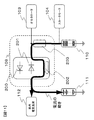
- FIG. 11 shows the form of power interchange from the first storage battery 110 to the second storage battery 111 and the in-vehicle electric load 112 in terms of current movement.
- the controller 115 performs the first switching.
- the power interchange circuit 109 is controlled so that the contact of the element and the contact of the second switching element 203 are both closed. By doing so, the power of the first storage battery 110 is discharged, and the discharged power of the first storage battery 110 is charged in the second storage battery 111 or supplied to the in-vehicle electric load 112.
- the electric power of the 1st storage battery 110 is discharged, and the charge voltage V1 of the 1st storage battery 110 can be reduced.
- the discharge lower limit voltage Vd of the first storage battery is determined based on the vehicle speed information of the vehicle 100.
- the vehicle speed is high, by reducing the discharge lower limit voltage Vd of the first storage battery, it is possible to increase the power recovery amount during deceleration regeneration without decreasing the number of idling stops. That is, since the kinetic energy increases as the vehicle speed increases, the electric power obtained by the deceleration regeneration increases. Therefore, the 1st storage battery 110 can increase the margin which the 1st storage battery 110 can accept regenerative electric power by discharging more electric power. In this way, the amount of power recovered during deceleration regeneration increases.
- the discharge lower limit voltage Vd of the first storage battery is increased.
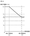
- FIG. 12 shows an example of the relationship between the discharge lower limit voltage Vd of the first storage battery and the vehicle speed of the vehicle 100.
- the discharge lower limit voltage Vd is equal to the charge upper limit voltage VU of the first storage battery 110.
- the discharge lower limit voltage Vd decreases.
- the discharge lower limit value Vd in accordance with the vehicle speed, it is possible to increase the amount of recovered regenerative power without reducing the number of idling stops.
- the regenerative lower limit vehicle speed va is a lower limit value of the vehicle speed that does not impair the drivability of the engine 101 even if fuel cut (stop of fuel supply to the engine 101) is performed in a state where the engine 101 is brought from the axle 107.
- the state where the engine 101 is driven from the axle 107 is a state where the engine 101 is driven by the rotation of the wheel 108 when the clutch is engaged by the lockup mechanism, for example.
- the vehicle speed at which the drivability of the engine 101 is not impaired is, for example, a vehicle speed at which engine stall does not occur in the engine 101.
- the regeneration lower limit vehicle speed va is changed to various values depending on the type of transmission, the gear ratio, the clutch engagement state, and the like. Therefore, it is preferable that the regeneration lower limit vehicle speed va is included in a range of approximately 10 km / h to 40 km / h. As the regeneration lower limit vehicle speed va decreases, the amount of regenerative electric power obtained increases. Therefore, the regeneration lower limit vehicle speed va is set at a lower vehicle speed side, that is, a value included in the range from 10 km / h to 20 km / h in the above-mentioned range of approximately 10 km / h to 40 km / h. More preferably. The regeneration lower limit vehicle speed va is most preferably set to a value included between 10 km / h and 15 km / h.
- the discharge lower limit voltage Vd becomes equal to the voltage V2 of the second storage battery 111.
- the discharge lower limit voltage Vd becomes equal to the voltage V2 of the second storage battery 111, the discharge lower limit voltage Vd does not fall below the voltage V2 of the second storage battery 111 even if the vehicle speed is further greater than the maximum discharge vehicle speed vb.
- the lower limit voltage Vd remains equal to the voltage V2 of the second storage battery 111.
- the charging voltage V1 of the first storage battery 110 is The maximum discharge vehicle speed vb is determined in advance so as to be included in a range of a predetermined ratio of a voltage range in which charge / discharge can be performed in the battery capacity of the storage battery 110, for example, in a range from 50% to 100%.
- the vehicle speed at which a sufficient amount of power is recovered by the deceleration regeneration is the maximum discharge vehicle speed vb.
- the maximum discharge vehicle speed vb needs to exceed at least the regeneration lower limit vehicle speed va. Moreover, it is preferable that the maximum discharge vehicle speed vb is set so that the first battery 110 can be charged to the vicinity of the charge upper limit voltage VU on the occasion of the coming deceleration regeneration. Therefore, the maximum discharge vehicle speed vb is preferably set to a value between 40 km / h and 100 km / h. More preferably, the maximum discharge vehicle speed vb is a value between 50 km / h and 80 km / h. Most preferably, a speed of approximately 60 km / h is set as the maximum discharge vehicle speed.
- the coordinate position where the discharge lower limit voltage Vd when the vehicle speed is the maximum discharge vehicle speed vb is represented by the voltage V2 of the second storage battery 111 and the discharge lower limit voltage Vd when the vehicle speed is the regeneration lower limit vehicle speed va are
- the lower limit voltage Vd when the vehicle speed is included between the regeneration lower limit vehicle speed va and the maximum discharge vehicle speed vb can be represented by a line connecting the coordinate position represented by the charge upper limit voltage VU with a straight line or a curve.
- the discharge lower limit voltage Vd changes according to the vehicle speed information.
- FIG. 13 shows a case where the charging voltage V1 of the first storage battery 110 is smaller than the voltage necessary for driving the starter motor 104 for starting the engine 101, and the engine 101 is not driven before starting.
- FIG. 5 is a diagram showing how a part of the electric power discharged by the second storage battery 111 is charged into the first storage battery 110 by the movement of current. The remainder of the electric power discharged by the second storage battery 111 is supplied to the in-vehicle electric load 112.
- the controller 115 controls the power interchange circuit 109 so that the contact point of the first switching element 202 and the contact point of the second switching element 203 are both closed.
- the electric power of the second storage battery 111 discharged is charged to the first storage battery 110 via the first switching element 202 and the second switching element 203.
- the charge state in which the charging voltage V1 of the first storage battery 110 is restored to the voltage necessary for driving the starter motor 104 is obtained.
- the charging state in which the charging voltage V1 of the first storage battery 110 is restored to the voltage necessary for driving the starter motor 104 is obtained, the charging of the first storage battery 110 ends.
- the in-vehicle power supply control device configured by the power interchange circuit 109 and the controller 115 stands by in the safe mode described above in preparation for starting the engine 101.
- the charging voltage V1 of the first storage battery 110 is lower than the voltage V2 of the second storage battery 111.
- the controller 115 causes the first storage battery 110 to start. It is determined that the charging state is not such that the motor 104 can be driven.
- the voltage difference between the voltage V1 of the first storage battery 110 and the voltage V2 of the second storage battery 111 is not less than 0 and included in the voltage range not more than the forward drop voltage of the first rectifying element 201.
- the controller 115 controls the power interchange circuit 109 to open the contact point of the first switching element 202 and to close the contact point of the second switching element 203 until the power interchange circuit 109 is turned on.
- the discharged power of the second storage battery 111 is charged into the first storage battery 110 via the first rectifying element 201 and the second switching element 203.
- FIG. 14 shows the power distribution mode when the generated power of the alternator 103 is charged to the first storage battery 110 and the second storage battery 111 so that the first storage battery 110 and the second storage battery 111 have the same voltage. Is shown.
- Charging mode (2) when the accelerator pedal 121 of the vehicle 100 is not depressed and the brake pedal 122 is hardly depressed, the electric power generated by the alternator 103 is the second storage battery. Only 111 is charged.
- Charging mode (1) when the accelerator pedal 121 of the vehicle 100 is not depressed and the brake pedal 122 is depressed, the first storage battery 110 and the second storage battery 111 The electric power generated by the alternator 103 is preferentially charged in the first storage battery 110 until the voltage difference between the two exceeds the forward drop voltage V32 of the second rectifying element 200.
- the idling stop frequently occurs, so that the power of the first storage battery 110 is consumed, and the second storage battery 111 is used by using the auxiliary equipment for a long time. Electric power is also consumed.
- the voltage V1 of the first storage battery 110 and the voltage V2 of the second storage battery 111 rise equally. It is preferable to do.
- the controller 115 When the alternator 103 is generating power, and when the voltage V1 of the first storage battery 110 falls below the first lower limit value and the voltage V2 of the second storage battery 111 falls below the second lower limit value, the controller 115 The circuit 109 is controlled so that the contact of the first switching element 202 is opened and the contact of the second switching element 203 is closed.
- the first storage battery 110 is charged with generated power obtained by driving the alternator 103 until the voltage V1 of the first storage battery 110 becomes the voltage V2 of the second storage battery 111 or higher.
- the controller 115 controls the power interchange circuit 109 so that the contact of the first switching element 202 is closed together with the contact of the second switching element 203.
- the controller 115 controls the power interchange circuit 109 by transmitting a control signal to the power interchange circuit 109 by the controller 115.
- the selection conditions for each of the drive modes described above by the controller 115 will be described in detail.
- FIG. 15 shows a state transition diagram when the controller 115 determines and controls each drive mode.
- the controller 115 prepares for the engine start by executing the engine stop process S100.
- the controller 115 executes the charge state determination process S101 and waits until there is an engine start request.
- the controller 115 determines that the charging voltage V1 of the first storage battery 110 is lower than the voltage capable of driving the starter motor 104 in the charging state determination S101
- the controller 115 performs the processing S102 of “VI. Interchange mode (2)”. Execute.
- the controller 115 restarts the engine 101 when the second storage battery 111 consumes electric power by supplying power to the in-vehicle electric load 112 during the automatic engine stop and the charging voltage of the second storage battery 111 decreases (processing).
- the alternator 103 makes a transition to a state where the second storage battery 111 can be charged, and causes the alternator 103 to charge the second storage battery 111 (processing S111).
- this control ends (process S109).
- the state transitions to the engine start determination process S105.
- the controller 115 determines whether the engine 115 in either the "I. engine start mode” process S106 or the “II. Safe mode” process S107 depending on the state of charge of the first storage battery 110 and the second storage battery 111. A determination is made as to whether a start is performed. If the engine start fails in process “I. Engine start mode” S106, engine start is attempted in process “S107” in “II. Safe mode”. If the engine start is successful, the state transitions to the engine driving process S110. When the engine start fails in the “II. Safe mode” process S107, the controller 115 notifies the user of an engine start error through the error process S108, and this control ends (process S109).
- the controller 115 selects and executes the process S111 of “IV. Charging mode (2)” as the standby mode of the power interchange circuit 109. From the state in which the process S111 of “IV. Charge mode (2)” is executed, the process S112 of “V. interchange mode (1)”, the process S113 of “III. Charge mode (1)”, “VII. Charge mode” It is possible to transition to each state in which each process of (3) "process S114 and engine automatic stop process S115 is executed.
- the process S112 of “V. interchange mode (1)” can be performed. Transition to the state.
- the accelerator pedal 121 that has been depressed is returned in the state of the process S112 in the “V. interchange mode (1)” and the vehicle 100 starts coasting, the process S111 in the “IV. Charge mode (2)” is executed. In the state of inertia running, the second storage battery 111 is charged with the generated power of the alternator 103.
- the first storage battery 110 and the second storage battery 111 detected by the charge state monitoring devices 113 and 114 Based on the charge state information, it may be detected that the voltage V1 of the first storage battery 110 is lower than the first lower limit value and the voltage V2 of the second storage battery 111 is lower than the second lower limit value. In that case, the voltage V1 of the first storage battery 110 is further reduced so as not to reach the minimum discharge lower limit voltage VL, and the voltage V2 of the second storage battery 111 is further reduced so as not to reach the minimum discharge lower limit voltage Vl.
- the charge to the 1st storage battery 110 and the 2nd storage battery 111 is performed equally. Therefore, when the vehicle 100 is coasting or traveling at low speed in the state of the process S111 of “IV. Charging mode (2)” and the alternator 103 is generating power, the voltage V1 of the first storage battery 110 is the first lower limit. When the voltage V2 of the second storage battery 111 is lower than the second lower limit value, the process shifts to a state in which the process S114 of “VII. Charging mode (3)” is executed, and the first storage battery 110 and the second storage battery 111 Is charged. When the engine automatic stop process S115 is executed in the state of the process S111 in “IV. Charging mode (2)”, the state transitions to the engine stop process S100.
- the transition from each state to another different state includes the charge state monitoring device 113, the charge state monitoring device 114, the accelerator pedal depression amount detection device 116, the brake pedal depression amount detection device 117, and the vehicle speed detection device. This is performed based on information transmitted from at least one of 118 to the controller 115.
- the information transmitted from the vehicle speed detection device 118 is vehicle speed information.
- the information transmitted from the accelerator pedal depression amount detection device 116 is information relating to the depression amount of the accelerator pedal 121.
- Information transmitted from the brake pedal depression amount detection device 117 is information relating to the depression amount of the brake pedal 122.
- Information transmitted from the charge state monitoring device 113 is information related to the charge state of the first storage battery 110.
- the information transmitted from the charge state monitoring device 114 is information related to the charge state of the second storage battery 111.
- the state transition described above may be performed in accordance with the passage of time measured by a timer (not shown) provided by the controller 115 or the like.
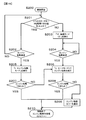
- FIG. 16 shows a flowchart of determination control executed by the controller 115 in the state transition from the engine stop process S100 to the engine drive process S101.
- the controller 115 determines in step S201 that the charging state of the first storage battery 110 is a charging state in which the starter motor can be driven, and in step S202, determines that there is an engine start request. Then, in step S205, it is determined to execute the processing of “I. Engine start mode”. If the controller 115 determines in step S202 that there is no engine start request, the control returns to step S201.
- the controller 115 determines whether or not the engine has been started in step S207. If the engine has been successfully started, the control is performed in step S210. The process is terminated, and the state transitions to the engine driving process S101. When engine start fails in step S207, step S206 described later is performed.
- step S201 determines in step S201 that the charging state of the first storage battery 110 is not a charging state in which the starter motor can be driven
- step S203 the controller 115 determines to execute “VI. Interchange mode (2)”. If the controller 115 determines in step S204 that there is no engine start request, the controller 115 waits until there is an engine start request, and if there is an engine start request, step S206 is performed. In step S206, when the process of “II. Safe mode” is executed, the engine is started. In step S208, the controller 115 determines whether or not the engine has been started. If the engine has been successfully started, the control ends in step S210, and the state transitions to the engine driving process S101. If engine start fails in step S208, in step S209, the controller 115 notifies the user of an engine start error. In step S210, this control ends, and the state transitions to the engine driving process S101.
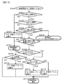
- FIG. 17 shows a flowchart of determination control executed by the controller 115 in the state transition from the engine driving process S101 to the engine stop process S100.
- the controller 115 determines that the charging voltage V2 of the second storage battery 111 obtained by the charging state monitoring device 114 of the second storage battery 111 is the second lower limit during engine driving in step S301. It is determined whether or not the value is below. If an affirmative determination is made, in step S302, the controller 115 determines whether or not the charging voltage V1 of the first storage battery 110 obtained by the charging state monitoring device 113 of the first storage battery 110 is lower than the first lower limit value during engine driving. Determine whether.
- step S301 or S302 the controller 115 determines to execute “VII. Charging mode (3)” in step S303, and charging of the first storage battery 110 and the second storage battery 111 is performed. As shown in step S307, this control returns to step S300.
- step S304 If the voltage V1 of the first storage battery 110 is greater than or equal to the first lower limit value in step S301 and the voltage V2 of the second storage battery 111 is greater than or equal to the second lower limit value in step S302, the controller 115 causes the engine in step S304 to It is determined whether or not the automatic stop condition is satisfied. In step S304, if the engine automatic stop condition is satisfied, the engine automatic stop process is performed. In step S305, the present control is terminated, and the state transitions to the engine stop process S100.
- the charging of the second storage battery that supplies power to the in-vehicle electric load 112 by determining the charging state of the first storage battery and the second storage battery in steps S301 and S302 before the controller 115 determines the engine stop condition. It is possible to prevent the voltage V2 and the charging voltage V1 of the first storage battery that supplies power to the starter motor 04 that starts the engine from being significantly reduced.
- step S304 If it is determined in step S304 that the engine stop condition is not satisfied and the engine 101 is driven and the vehicle 100 is traveling or is in a state where it can travel, in step S306, the controller 115 It is determined whether the vehicle speed of 100 is equal to or higher than the regeneration lower limit vehicle speed va. If an affirmative determination is made in step S306, in step S308, the controller 115 determines whether or not the vehicle speed is equal to or higher than the regeneration lower limit vehicle speed va and the accelerator pedal 121 is in an accelerated state. If an affirmative determination is made in step S308, the controller 115 determines in step S309 that the charging voltage V1 of the first storage battery 110 is greater than the discharge lower limit voltage Vd, in step S310, “V. 1) ”is executed. In “V.
- step S308 determines in step S308 that the accelerator pedal 121 has been returned and it is determined in step S311 that the brake pedal 122 has not been depressed, that is, if the vehicle 100 is coasting, “IV. It decides to execute “charging mode (2)”. In “IV. Charging mode (2)”, only the second storage battery 111 is charged. If the controller 115 determines in step S311 that the brake pedal 122 has been depressed and that strong deceleration regeneration is possible, then in step S313, the controller 115 determines to execute “III. Charging mode (1)”. . In this way, by changing the strength of the deceleration regeneration by the brake operation, the driver can feel the sudden deceleration and the ride comfort can be improved.
- the on-vehicle power supply control device described above includes a power interchange circuit 109 and a controller 115.
- the power interchange circuit 109 includes a first switching element 202.
- the first switching element 202 is disposed between the first storage battery 110 and the second storage battery 111 and between the first storage battery 110 and the in-vehicle electric load 112.
- the first storage battery 110 is mounted on the vehicle 100 and supplies power to the starter motor 104 that transmits torque necessary for starting the engine 101 to the engine 101.
- the second storage battery 111 is mounted on the vehicle 100 and supplies electric power to the in-vehicle electric load 112 including auxiliary machines in the vehicle 100.
- the power interchange circuit 109 includes a second switching element 203 along with the first switching element 202.
- the second switching element 203 is disposed between the first switching element 202 and the first storage battery 110 and between the alternator 103 and the first storage battery 110.
- the controller 115 sets the discharged first storage battery 110 to the second storage battery 111.
- the contact of the first switching element 202 and the contact of the second switching element 203 And control to close together.
- the controller 115 uses the electric power to charge the first storage battery 110 with the electric power generated by the alternator 103.
- the interchange circuit 109 is controlled to open the contact point of the first switching element 202 and close the contact point of the second switching element 203. Thereby, it becomes possible to collect
- the control of the in-vehicle power supply control device includes the charging voltage V1 of the first storage battery 110, the charging upper limit voltage VU, the minimum discharge lower limit voltage VL, the discharge lower limit voltage Vd, and the charging voltage V2 of the second storage battery 111.
- V1 the charging voltage
- VU the charging upper limit voltage
- VL the minimum discharge lower limit voltage
- Vd the discharge lower limit voltage
- V2 the charging voltage
- V1 of the first storage battery 110 the charging upper limit voltage VU
- VL the minimum discharge lower limit voltage
- Vd discharge lower limit voltage
- V2 of the second storage battery 111 the charging voltage V2 of the second storage battery 111.
- the output of the engine 101 is used as the driving force of the vehicle 100.
- the present invention is also applied to an in-vehicle power supply control device of a hybrid electric vehicle that uses both an engine and a motor as a power source of the vehicle 100. it can.
- an automatic transmission or a manual transmission can be used as the transmission 105 used in the above-described embodiment.
- the clutch pedal depression amount, shift position, or the like may be used.
- the present invention can also be applied to an in-vehicle power supply control device for a vehicle in which the engine stops before the vehicle completely stops.
Landscapes
- Engineering & Computer Science (AREA)
- Mechanical Engineering (AREA)
- Control Of Charge By Means Of Generators (AREA)
- Charge And Discharge Circuits For Batteries Or The Like (AREA)
Abstract
車載蓄電池の利用効率を向上させる。 本発明に係る車載電源制御装置は、スタータモータへ電力を供給する第1蓄電池と、電気負荷へ電力を供給する第2蓄電池との間であって、かつ第1蓄電池と電気負荷との間に配置される第1スイッチング素子を含むとともに、第1スイッチング素子と第1蓄電池との間であって、かつオルタネータと第1蓄電池との間に配置される第2スイッチング素子を含む電力融通回路と、車速が回生下限車速以上であって、かつ第1蓄電池の第1電圧が放電下限電圧よりも大きいとき、第1蓄電池の電力が第2蓄電池に充電されるようにするために、電力融通回路に対して、第1スイッチング素子の第1接点と第2スイッチング素子の第2接点とがともに閉じる制御を行う制御回路とを有する。
Description
本発明は、車載電源制御装置に関する。
自動車のエンジン始動にはスタータモータに代表される電動機が用いられており、電動機は自動車に搭載された蓄電池からの電力により駆動されている。スタータモータがエンジンを始動する際には瞬間的な大電力が必要であり、エンジンの始動用電源としての蓄電池は大電流による放電を要求される。特許文献1には、キャパシタをエンジンの始動用電源として用いる例が示されている。
特許文献1はキャパシタによるエンジンの始動性をより高めるために、始動電力を供給しない他の蓄電池から電力供給を受け、来たるエンジン始動の機会のために、キャパシタを高電圧に充電しておく技術が開示されている。しかしながら、キャパシタへ常に電力を蓄えた状態を維持していると、回生時に回収できる電力エネルギが大幅に減少しまうという問題がある。
請求項1に記載の車載電源制御装置は、車両に搭載され、エンジンの始動に必要なトルクをエンジンへ伝達するスタータモータへ電力を供給する第1蓄電池と、車両に搭載され、車両内の補機類を含む電気負荷へ電力を供給する第2蓄電池との間であって、かつ第1蓄電池と電気負荷との間に配置される第1スイッチング素子を含むとともに、第1スイッチング素子と第1蓄電池との間であって、かつオルタネータと第1蓄電池との間に配置される第2スイッチング素子を含む電力融通回路と、車両の車速が回生下限車速以上であって、かつ第1蓄電池の第1電圧が放電下限電圧よりも大きいとき、放電された第1蓄電池の電力が第2蓄電池に充電されるようにするために、電力融通回路に対して、第1電圧が放電下限電圧に等しくなるまで、第1スイッチング素子の第1接点と第2スイッチング素子の第2接点とがともに閉じる制御を行う制御回路とを備え、車両のアクセルペダルが踏み込まれず、かつ車両のブレーキペダルが踏み込まれているとき、 制御回路は、オルタネータが発電する電力が第1蓄電池に充電されるようにするために、電力融通回路に対して、第1スイッチング素子の第1接点が開くとともに第2スイッチング素子の第2接点が閉じる制御を行うことを特徴とする。
本発明によれば、車載蓄電池の利用効率が向上する。
図1を用いて、本発明の一実施の形態における車載電源制御装置及び周辺装置の接続構成を説明する。車載電源制御装置及び周辺装置は車両100に含まれる。図1において、車載電源制御装置はコントローラ115及び電力融通回路109を含み、周辺装置はコントローラ115及び電力融通回路109以外の装置を含む。車両100には、エンジン101の駆動力を伝達するベルト102によって回転駆動される発電機であるオルタネータ103が含まれる。エンジン101の始動時には、始動機であるスタータモータ104によって、エンジン始動に必要なトルクがエンジン101へ伝達される。
エンジン101には変速機105及びディファレンシャル106が接続される。車軸107が車輪108を駆動する。オルタネータ103によって発電された電力は、電力融通回路109を介して第1蓄電池110、第2蓄電池111、及び車内電気負荷112へ分配される。
第1蓄電池110及び第2蓄電池111には、それぞれ充電状態監視装置113及び114が組みつけられる。充電状態監視装置113及び114は、それぞれ第1蓄電池110及び第2蓄電池111の充電状態を監視し、充電状態の診断結果をコントローラ115へ送信する。アクセルペダル121の踏み込み量を検出するアクセルペダル踏み込み量検出装置116及びブレーキペダル122の踏み込み量を検出するブレーキペダル踏み込み量検出装置117も同様に、コントローラ115へ、それぞれアクセルペダル踏み込み量及びブレーキペダル踏み込み量の検出結果を送信する。車速検出装置118は、自動車の車速を計測し、コントローラ115へ車速の測定結果を送信する。
コントローラ115は、上述した各装置から得た診断結果、検出結果、及び測定結果といった情報に基づき、オルタネータ103、スタータモータ104、及び電力融通装置109へ制御信号を送信することによって、オルタネータ103、スタータモータ104、及び電力融通装置109を制御する。コントローラ115は、プログラムや演算処理を実行するCPU、CPUが実行するプログラム等を記憶するROM、一時的に情報を記憶するRAM、及び情報の送受信に用いる入出力ポート等を含む。RAMに一時的に記憶される情報は、コントローラ115のCPUによる演算結果と、上述した各装置によってコントローラ115へ送信された診断結果、検出結果、及び測定結果とを含む。
第1蓄電池110はスタータモータ104へ電力を供給し、第2蓄電池111は車両100内の補機類を含む車内電気負荷112へ電力を供給する。
第1蓄電池110は、電気二重層キャパシタ、及び非対称キャパシタのうちの少なくとも一方を含む組電池であることが好ましい。電気二重層キャパシタは、電池内の電極界面で生じる物理現象である電気二重層を応用した蓄電池であればよい。活性炭、カーボンナノチューブ等の炭素材料や金属などが、電極として好適に用いられる。電極間には、水溶液や有機溶媒等が充填される。
非対称キャパシタは、一方の電極として、前述の電気二重層を応用した電極を有し、かつ他方の電極として、インターカレーション型電極、または溶解析出型電極を有する蓄電池であればよい。非対称キャパシタとして、例えばリチウムイオンキャパシタを好適に用いることができる。
第2蓄電池111は、リザーブ型蓄電池、またはロッキングチェア型蓄電池であることが好ましい。リザーブ型蓄電池は、主に金属の溶解析出反応によって電荷が交換されることで充放電を可能にした蓄電池である。リザーブ型蓄電池として、例えば鉛酸蓄電池を好適に用いることができる。ロッキングチェア型蓄電池は、正極及び負極としてインターカレーション型電極が用いられ、かつイオンが充放電によって正極と負極との間を往復することで電荷が交換される蓄電池であればよい。ロッキングチェア型蓄電池として、例えばリチウムイオン二次電池、及びニッケル水素二次電池などが挙げられる。
第1蓄電池110、及び第2蓄電池111は、それぞれ最小構成の単位セルが直列及び並列に接続されて構成される。例えば、第1蓄電池110において、リチウムイオンキャパシタと電気二重層キャパシタとが組み合わされて用いられるなど、複数種類の蓄電池を組み合わせた組電池が使用されることとしても良い。同様に、第2蓄電池111において、複数種類の蓄電池を組み合わせた組電池が使用されることとしても良い。
第1蓄電池110は、電気二重層キャパシタ、及び非対称キャパシタのうちの少なくとも一方を含む組電池であり、第2蓄電池111は、リザーブ型蓄電池、及びロッキングチェア型蓄電池のうちの少なくとも一方を含む組電池であればよい。このようにすることで、第1蓄電池110は、スタータモータがエンジンを始動する際に必要な瞬間的な大電流による放電が可能であり、かつ急速充電が可能であるとともに、第2蓄電池111の電池寿命を延ばすことができる。
第2蓄電池111の電池容量を第1蓄電池110の電池容量で除算して得られた商の値が、10以上200以下であることが好ましい。「III.充電モード(1)」において後述するように、充電モード(1)においては第2電池111よりも第1蓄電池110が優先的に充電される。第2蓄電池111の電池容量を第1蓄電池110の電池容量で除算して得られた商の値が10以上の場合は、第1蓄電池110の電池容量が第2蓄電池111の電池容量に対して大きくなり過ぎないため、充電モード(1)において、第1蓄電池110の優先的な充電に要する時間が抑えられ、車速の減速による回生時に第2蓄電池111が充分に充電されない可能性が抑えられる。第1蓄電池110の優先的な充電に要する時間が抑えられるため、第1蓄電池110を大量に搭載する必要が無く、安価に車載電源を提供することができる。
第2蓄電池111の電池容量を第1蓄電池110の電池容量で除算して得られた商の値が200以下の場合は、第1蓄電池110の電池容量が小さ過ぎないため、スタータモータ104が第1蓄電池110からの供給電力のみを使ってエンジン101を始動できる可能性が高く、アイドリングストップ回数の減少を抑止して燃費低減を図ることができる。すなわち、第2蓄電池111の電池容量を第1蓄電池110の電池容量で除算して得られた商の値が10以上200以下であれば、良好な電力分配が可能となるため、第2蓄電池111へも充電が行われ、大量に第1蓄電池110を車両100に搭載することも必要無いため、安価に車載電源を提供することが可能である。
図2は、電力融通回路109の構成の一例を示す。電力融通回路109は、少なくとも、第1蓄電池110の正極端子と第2蓄電池111の正極端子とを短絡することを可能にする第1スイッチング素子202と、電力融通回路109に対して第1蓄電池110を電気的に接続したり切断したりすることが可能な第2スイッチング素子203とを含む。第1スイッチング素子202は、第1蓄電池110と第2蓄電池111との間であって、かつ第1蓄電池110と車内電気負荷112との間に配置される。第2スイッチング素子203は、第1スイッチング素子202と第1蓄電池110との間であって、かつオルタネータ103と第1蓄電池110との間に配置される。
電力融通回路109は、さらに、第2蓄電池111から第1蓄電池110へ向かう方向D1の電圧または電流を制限する第1整流素子201を含むことが好ましい。第1整流素子201は、第2スイッチング素子203と第2蓄電池111及び車内電気負荷112との間に、第1スイッチング素子202と並列に配置される。電力融通回路109は、さらに、第1蓄電池110から第2蓄電池111へ向かう方向D2の電圧または電流を制限する第2整流素子200を含むことが好ましい。第2整流素子200は、第2スイッチング素子203と第2蓄電池111及び車内電気負荷112との間に、第1スイッチング素子202及び第1整流素子201と並列に配置される。
第1整流素子201及び第2整流素子200は、それぞれ、図2に示すように1つまたは複数のダイオード204を直列に接続することで構成できる。ダイオード204の1つの順方向降下電圧はおよそ0.5V~1.5Vであるため、第1整流素子201による電圧制御及び第2整流素子200による電圧制御は、ダイオード204の直列接続数によって任意かつ好適に提供可能である。図2は、3個のダイオード204が直列に接続されることによって構成された第2整流素子200と、1個のダイオード204で構成された第1整流素子200とを示しているが、第1整流素子201及び第2整流素子200において、接続するダイオード204の個数は、図2に示す例に特に限定されるものではない。第1整流素子201及び第2整流素子200として、それぞれ任意かつ好適な個数のダイオード204を用いることができる。
図2に示した電力融通回路109において、第1整流素子201及び第2整流素子200は、ダイオード204を用いた電圧制御式の整流素子である。第1整流素子201及び第2整流素子200は、それぞれスイッチング素子を用いた電流制御式の整流素子であってもよい。このような電流制御式の整流素子として、絶縁ゲートバイポーラトランジスタ(Insulated Gate Bipolar Transistor,IGBT)や、サイリスタ、MOS-FET(Metal Oxide Semiconductor - Field Effect Transister)などの半導体スイッチを用いることが好ましい。
第1スイッチング素子202及び第2スイッチング素子203として、それぞれマグネットスイッチや半導体リレーが用いられることとしてもよい。第1スイッチング素子202として半導体スイッチが用いられる場合、電力融通回路109での半導体スイッチの配置方向に依存して順方向電流制御となる場合や逆方向電流制御となる場合がある。したがって、図3に示すように、第1整流素子201及び第2整流素子200と並列に配置されたスイッチング素子202a及び202bが、互いに逆の配置方向に並列して配置されることで、制御される電流の両方向を考慮した目標特性が得られるようにしてもよい。なお、スイッチング素子202a及び202bが第1スイッチング素子202を構成する。
電圧制御式または電流制御式の第1整流素子201及び第2整流素子200が、図3に示した第1スイッチング素子202を兼ねることとしてもよい。図4に示すように電流制御式の整流素子によって第1の整流素子201及び第2の整流素子200がそれぞれスイッチング素子202a及び202bの機能を兼ねることで、回路の簡略化を図ることができる。なお、半導体スイッチであるスイッチング素子202a及び202bが第1スイッチング素子202を構成する。このような場合には、充電状態監視装置113及び114によって計測される電池の電圧をコントローラ115が比較する。コントローラ115は、充電状態監視装置113及び114によって計測される電池の電圧差が所定値となるように、第1整流素子201及び第2整流素子200を制御する。例えば、コントローラ115からパルス状のスイッチング信号を出力する際のデューティ比を変更することにより電力融通回路109を流れる電流値を調節することができる。なお、デューティ比は、パルス一周期間に対するパルス立ち上がり時間の割合である。
第2スイッチング素子203の付近には、急峻な電力入力を緩和するために、図3に示すような大きなリアクタンス205が挿入されてもよいし、抵抗器206が含まれてもよいし、スナバ回路207が第2スイッチング素子203と並列に実装されてもよい。このような回路を保護するために適当な任意の回路素子がこの回路に実装されていてもよい。
第1整流素子201及び第2整流素子200に電圧制御式の整流素子が用いられた場合、第1整流素子201及び第2整流素子200の両端の電圧差に対する電流の特性は、図5及び図6に示される。第1整流素子201及び第2整流素子200の両端の電圧差に対する電流の特性は、第1スイッチング素子202の接点が開いているときは図5に示され、第1スイッチング素子202の接点が閉じているときは図6に示される。図5及び図6のいずれにおいても、第1整流素子201及び第2整流素子200の両端の電圧差は、その両端のうちの一方に対応する第2蓄電池111側を基準とし、方向D2に流れる電流が正の値をとり、方向D1に流れる電流が負の値とることとする。コントローラ115によって第1スイッチング素子202が駆動されていない場合、すなわち第1スイッチング素子202の接点が開いている場合は、図5に示すように、第1蓄電池110及び第2蓄電池111の間に、第1整流素子201及び第2整流素子200のそれぞれの順方向降下電圧が印加されるまでは電流が流れないので、第1整流素子201及び第2整流素子200の両端の電圧差は保持され、すなわち第1蓄電池110及び第2蓄電池111の間の電圧差は保持される。
コントローラ115が第1スイッチング素子202を駆動することで第1スイッチング素子202の接点が閉じるため、第1整流素子201及び第2整流素子200の両端の電圧差にほぼ関係なく電流を流すことができるようになる。すなわち、第1整流素子201及び第2整流素子200のそれぞれの順方向降下電圧に関わらず、第1蓄電池110及び第2蓄電池111のうち、より電圧の高い電池から優先的に放電させることや、第1蓄電池110及び第2蓄電池111のうちの一方の電池の放電電力で電圧の低い他方の電池を充電することも可能になる。第1整流素子201及び第2整流素子200として、電圧制御式の整流素子及び電流制御式の整流素子のうちのいずれか一方のみが用いられてもよいし、第1整流素子201及び第2整流素子200のうちの一方に電圧制御式の整流素子が用いられて、かつ他方に電流制御式の整流素子が用いられてもよい。
第1蓄電池110は直列に接続されたn1個の単独セルを含む組電池であり、それらn1個の単電池セルの各々は、完全放電時に電圧V11、満充電時に電圧V11よりも大きい電圧V12となる。したがって、第1蓄電池110の最低放電下限電圧VLは各単電池セルの電圧V11のn1倍に等しく、第1蓄電池110の最低放電下限電圧VLよりも大きい充電上限電圧VUは各単電池セルの電圧V12のn1倍に等しい。第2蓄電池111は、直列に接続されたn2個の単電池セルを含む組電池であり、第2蓄電池111の定格電圧Cは、各単電池セルの定格電圧C0のn2倍に等しい。
第2蓄電池111の充電上限電圧Vuは、定格電圧Cよりも大きく、かつ第1蓄電池110の充電上限電圧VUよりも小さいことが好ましい。第2蓄電池111の最低放電下限電圧Vlは、定格電圧Cよりも小さく、かつ第1蓄電池110の最低放電下限電圧VLよりも大きいことが好ましい。すなわち、VL<Vl<Vu<VUという関係が成り立つことが好ましい。このとき、第1蓄電池110と第2蓄電池111との間が電気的に接続されると、第1蓄電池110及び第2蓄電池111の充電電圧が大きいときは第1蓄電池110から第2電池111への電力融通が自動的に行われ得るとともに、第1蓄電池110及び第2蓄電池111の充電電圧が小さいときは第2蓄電池111から第1電池110への電力融通が自動的に行われ得る。
電力融通回路109に含まれる第1整流素子201は、例えば、直列に接続されたn3個のダイオード204を含み、第1整流素子201の順方向降下電圧V31は、各ダイオード204の順方向降下電圧V40のn3倍に等しい。電力融通回路109に含まれる第2整流素子200は、例えば、直列に接続されたn4個のダイオード204を含み、第2整流素子200の順方向降下電圧V32は、各ダイオード204の順方向降下電圧V40のn4倍に等しい。このとき、0≦V31<V32であって、かつVL<C-V31<C<C+V32<VUという関係が成り立つことが好ましい。その場合、電力融通回路109により、第2蓄電池111の定格電圧Cに対する電圧差が保持されるため、第1蓄電池110を、C-V31からC+V32までの電圧範囲で充放電に用いることが可能となる。
上述したVL<C<VUという関係に加えて、(VU-VL)÷2+VL≧Cという関係が成り立つことが好ましい。すなわち、第2蓄電池111の定格電圧Cは、第1蓄電池110の充電上限電圧VUよりも小さく、第1蓄電池110の最低放電下限電圧VLよりも大きく、第1蓄電池110の充電上限電圧VUから最低放電下限電圧VLを引いた差を2で除算して得られた商(VU-VL)÷2と、第1蓄電池110の最低放電下限電圧VLとの和以下であることが好ましい。例えばリチウムイオンキャパシタである第1蓄電池110は、例えば鉛酸蓄電池である第2蓄電池111と比較して大電力の入出力に適しているため、VL<C<VU、かつ(VU-VL)÷2+VL≧Cという関係が成り立つと、第1蓄電池110の利用率が向上する。
例えばリチウムイオンキャパシタである第1蓄電池110は、充電電圧と電池容量とがほぼ比例関係にあり、(VU-VL)÷2+VLという計算の結果として得られる電圧は、リチウムイオンキャパシタの電池容量のうちの充放電が可能な電圧範囲のほぼ50%に対応する電圧である。第1蓄電池110の構成が、(VU-VL)÷2+VL≧Cという関係を満足する構成であれば、第1蓄電池110が蓄積及び消費可能な電力のうちの少なくとも50%以上を、後述する「V.融通モード(1)」で第1蓄電池110が第2蓄電池111に向けて放電可能な電力、あるいは第1蓄電池110が車内電気負荷112に対して供給可能な電力とすることが、可能である。すなわち、第1蓄電池110の利用率を大きくすることができる。
一例として、第1蓄電池110に含まれる単電池セルの個数n1=4、その単電池セルの完全放電時の電圧V11=2.2[V]、その単電池セルの満充電時の電圧V12=3.8[V]、第1蓄電池110の最低放電下限電圧VL=8.8[V]、第1蓄電池110の充電上限電圧VU=15.2[V]、第2蓄電池111に含まれる単電池セルの個数n2=6、その単電池セルの定格電圧C0=2[V]、第2蓄電池111の定格電圧C=12[V]、第2蓄電池111の最低放電下限電圧Vl=10[V]、第2蓄電池111の充電上限電圧Vu=13.8[V]、第1整流素子201及び第2整流素子200に含まれるダイオード204の順方向降下電圧V40=0.6[V]、第1整流素子201に含まれるダイオード204の個数n3=2、第2整流素子200に含まれるダイオード204の個数n4=5、第1整流素子201の順方向降下電圧V31=1.2[V]、及び第2整流素子200の順方向降下電圧V32=3.0[V]は、上述した関係を満たす。
しかし、この例は一例であり、本発明はこの例に限られない。
しかし、この例は一例であり、本発明はこの例に限られない。
電力融通回路109及びコントローラ115によって提供される車載電源制御装置の電力融通処理時における駆動モードについて詳述する。
---I.エンジン始動モード---
図7は、通常のエンジン始動時における電力供給形態を、電流の動きで示している。第1蓄電池110の充電電圧V1が十分に高い場合は、コントローラ115は、第2スイッチング素子203の接点が開放されるように、電力融通回路109を制御する。その結果、第1蓄電池110を含む第1電源系と、第2蓄電池111を含む第2電源系とが電気的に切り離される。このように第1電源系が、第2電源系から切り離されることで、エンジン101始動時のスタータモータ104への電力供給に必要な大電力の放電が、すべて第1蓄電池110によって行われるため、第2電源系に干渉しないエンジン始動が可能になる。第2蓄電池111は大電力を放電する必要が無いので、エンジン始動に伴う電圧変動が第2蓄電池111では起こらず、第2蓄電池111によって車内電気負荷112へ安定的に電力が供給されるとともに、急速な放電による第2蓄電池111の劣化が抑制される。
図7は、通常のエンジン始動時における電力供給形態を、電流の動きで示している。第1蓄電池110の充電電圧V1が十分に高い場合は、コントローラ115は、第2スイッチング素子203の接点が開放されるように、電力融通回路109を制御する。その結果、第1蓄電池110を含む第1電源系と、第2蓄電池111を含む第2電源系とが電気的に切り離される。このように第1電源系が、第2電源系から切り離されることで、エンジン101始動時のスタータモータ104への電力供給に必要な大電力の放電が、すべて第1蓄電池110によって行われるため、第2電源系に干渉しないエンジン始動が可能になる。第2蓄電池111は大電力を放電する必要が無いので、エンジン始動に伴う電圧変動が第2蓄電池111では起こらず、第2蓄電池111によって車内電気負荷112へ安定的に電力が供給されるとともに、急速な放電による第2蓄電池111の劣化が抑制される。
---II.セーフモード---
図8は、セーフモードでのエンジン始動時における電力供給形態を、電流の動きで示している。第1蓄電池110の充電電圧V1が、十分に高くない場合が想定される。このような場合には、コントローラ115は、第2スイッチング素子203の接点が閉じられるように、電力融通回路109を制御する。その結果、第1電源系と第2電源系との電気的な接続が確保される。この場合、第1整流素子201の順方向降下電圧V31を上回る電圧差が、第1蓄電池110と第2蓄電池111との間に発生するまでは、第1蓄電池110のみによってスタータモータ104へ電力が供給される。第1蓄電池110の充電電圧V1がさらに低下すると、第1蓄電池110と第2蓄電池111との間の電圧差が第1整流素子201の順方向降下電圧V31を上回るため、第2蓄電池111による車内電気負荷112への電力供給用の放電に加えてスタータモータ104への電力供給用の放電が開始される。これにより、第1蓄電池110の充電電圧V1が万が一低下した場合においても、エンジン101を確実に始動することができる。
図8は、セーフモードでのエンジン始動時における電力供給形態を、電流の動きで示している。第1蓄電池110の充電電圧V1が、十分に高くない場合が想定される。このような場合には、コントローラ115は、第2スイッチング素子203の接点が閉じられるように、電力融通回路109を制御する。その結果、第1電源系と第2電源系との電気的な接続が確保される。この場合、第1整流素子201の順方向降下電圧V31を上回る電圧差が、第1蓄電池110と第2蓄電池111との間に発生するまでは、第1蓄電池110のみによってスタータモータ104へ電力が供給される。第1蓄電池110の充電電圧V1がさらに低下すると、第1蓄電池110と第2蓄電池111との間の電圧差が第1整流素子201の順方向降下電圧V31を上回るため、第2蓄電池111による車内電気負荷112への電力供給用の放電に加えてスタータモータ104への電力供給用の放電が開始される。これにより、第1蓄電池110の充電電圧V1が万が一低下した場合においても、エンジン101を確実に始動することができる。
---III.充電モード(1)---
図9は、車両100のアクセルペダル121が踏み込まれず、かつブレーキペダル122が踏み込まれているために、車速が減速する時の電力分配形態を、電流の動きで示している。このとき、オルタネータ103によって電力が発電される。第1蓄電池110の電圧と第2蓄電池111との間の電圧差が、第1整流素子201の順方向降下電圧V31以下であって、かつ第2整流素子200の順方向降下電圧V32以下の場合、コントローラ115は、第1スイッチング素子202の接点が開き、かつ第2スイッチング素子203の接点が閉じるように、電力融通回路109を制御する。こうすることによって、オルタネータ103によって発電された電力が、まず第1蓄電池110に優先的に充電される。
図9は、車両100のアクセルペダル121が踏み込まれず、かつブレーキペダル122が踏み込まれているために、車速が減速する時の電力分配形態を、電流の動きで示している。このとき、オルタネータ103によって電力が発電される。第1蓄電池110の電圧と第2蓄電池111との間の電圧差が、第1整流素子201の順方向降下電圧V31以下であって、かつ第2整流素子200の順方向降下電圧V32以下の場合、コントローラ115は、第1スイッチング素子202の接点が開き、かつ第2スイッチング素子203の接点が閉じるように、電力融通回路109を制御する。こうすることによって、オルタネータ103によって発電された電力が、まず第1蓄電池110に優先的に充電される。
第1蓄電池110の充電が進み、第1蓄電池110と第2蓄電池111との間の電圧差が第2整流素子200の順方向降下電圧V32を上回った際に、引き続き、第2スイッチング素子203を通じて、オルタネータ103によって発電された電力が第1蓄電池110に充電されるとともに、第2整流素子200を通じて、オルタネータ103によって発電された電力が第2蓄電池111へ充電される。すなわち、第2整流素子200の順方向降下電圧V32が設けられていることで、第1蓄電池110の電圧が小さいときは第1蓄電池110を優先的に充電することが可能となる。それとともに、第2整流素子200が作動する際の第1蓄電池110の電圧が、第2蓄電池111の充電電圧に応じて自動的に調整されるため、第2蓄電池111の充電電圧が極端に低下した状態が維持されることを防止できる。オルタネータ103によって発電された電力が、第2整流素子200を通じて、第2蓄電池111へ充電されるとともに、車内電気負荷112に対して給電されることとしてもよい。
---IV.充電モード(2)---
図10は、車両100のアクセルペダル121が踏み込まれず、かつブレーキペダル122もほとんど踏み込まれないために、惰性走行の状態で車速が減速する時または低速走行時の第2蓄電池111のみへの充電形態を、電流の動きで示している。このようにオルタネータ103の発電電力の第2蓄電池111のみへの充電が必要となる場合は、コントローラ115は、第2スイッチング素子203の接点が開くように電力融通回路109を制御する。これにより、第1電源系と第2電源系との間の電気的な接続が切り離される。加えて第1スイッチング素子202の接点が閉じるように、コントローラ115によって電力融通回路109が制御されることで、第2整流素子200を経由することなくオルタネータ103から第2蓄電池111へ充電電流を流すことが可能となる。そのため、充電電流が第2整流素子200を流れることによる電圧低下や電流損失を防止し、第2蓄電池111に対する損失の少ない充電を行うことが可能となる。オルタネータ103の発電電力が車内電気負荷112へ直接供給される場合、及び電力融通回路109が待機状態となる場合の、第1スイッチング素子202及び第2スイッチング素子203の開閉状態も、同様の状態となる。エンジン自動停止条件を満足してエンジン101が自動停止する際にも、同様の状態へ遷移した後に、エンジンが自動停止する。
図10は、車両100のアクセルペダル121が踏み込まれず、かつブレーキペダル122もほとんど踏み込まれないために、惰性走行の状態で車速が減速する時または低速走行時の第2蓄電池111のみへの充電形態を、電流の動きで示している。このようにオルタネータ103の発電電力の第2蓄電池111のみへの充電が必要となる場合は、コントローラ115は、第2スイッチング素子203の接点が開くように電力融通回路109を制御する。これにより、第1電源系と第2電源系との間の電気的な接続が切り離される。加えて第1スイッチング素子202の接点が閉じるように、コントローラ115によって電力融通回路109が制御されることで、第2整流素子200を経由することなくオルタネータ103から第2蓄電池111へ充電電流を流すことが可能となる。そのため、充電電流が第2整流素子200を流れることによる電圧低下や電流損失を防止し、第2蓄電池111に対する損失の少ない充電を行うことが可能となる。オルタネータ103の発電電力が車内電気負荷112へ直接供給される場合、及び電力融通回路109が待機状態となる場合の、第1スイッチング素子202及び第2スイッチング素子203の開閉状態も、同様の状態となる。エンジン自動停止条件を満足してエンジン101が自動停止する際にも、同様の状態へ遷移した後に、エンジンが自動停止する。
---V.融通モード(1)---
図11は、第1蓄電池110から第2蓄電池111及び車内電気負荷112への電力融通の形態を、電流の動きで示している。車両100の速度が後述する回生下限車速va以上となった場合であって、かつ第1蓄電池110の充電電圧V1が後述する放電下限電圧Vdよりも大きい場合には、コントローラ115は、第1スイッチング素子の接点及び第2スイッチング素子203の接点がともに閉じるように、電力融通回路109を制御する。こうすることで、第1蓄電池110の電力が放電され、放電された第1蓄電池110の電力が、第2蓄電池111に充電されたり、車内電気負荷112へ供給されたりする。このようにして第1蓄電池110の電力が放電されることで、第1蓄電池110の充電電圧V1を低下させることができる。
図11は、第1蓄電池110から第2蓄電池111及び車内電気負荷112への電力融通の形態を、電流の動きで示している。車両100の速度が後述する回生下限車速va以上となった場合であって、かつ第1蓄電池110の充電電圧V1が後述する放電下限電圧Vdよりも大きい場合には、コントローラ115は、第1スイッチング素子の接点及び第2スイッチング素子203の接点がともに閉じるように、電力融通回路109を制御する。こうすることで、第1蓄電池110の電力が放電され、放電された第1蓄電池110の電力が、第2蓄電池111に充電されたり、車内電気負荷112へ供給されたりする。このようにして第1蓄電池110の電力が放電されることで、第1蓄電池110の充電電圧V1を低下させることができる。
車両100の車速情報に基づき、第1蓄電池の放電下限電圧Vdが定まるのが好ましい。車速が大きいときは、第1蓄電池の放電下限電圧Vdを小さくすることで、アイドリングストップ回数を減少させることなく減速回生時の電力回収量を増加させることができる。すなわち、車速が大きくなるほど運動エネルギも増大するため、減速回生によって得られる電力が上昇する。そのため、第1蓄電池110が、より多くの電力を放電しておくことで、第1蓄電池110が回生電力を受け入れられる余裕を増やすことができる。こうして減速回生時の電力回収量が増加する。
車速があまり大きくない場合に、第1蓄電池110が過度に放電を行うと、減速回生時に回収できる電力が十分でないために、アイドリングストップ回数が減少する可能性が有る。したがって、車速が小さいときは、第1蓄電池の放電下限電圧Vdを大きくする。このように、車速に合わせて放電下限電圧Vdを設定することで、アイドリングストップ回数を減少させることなく回生電力の回収量を増大させることができる。
図12は、第1蓄電池の放電下限電圧Vdと車両100の車速との関係の一例を示す。図12に示すように、回生下限車速vaよりも車速が小さい場合、放電下限電圧Vdは、第1蓄電池110の充電上限電圧VUに等しい。車速が回生下限車速vaよりも大きくなるにつれて、放電下限電圧Vdは小さくなる。上述したように、車速に合わせて放電下限値Vdを設定することで、アイドリングストップ回数を減少させることなく回生電力の回収量を増大させることができる。
回生下限車速vaは、車軸107からエンジン101が連れまわされる状態でフューエルカット(エンジン101への燃料供給停止)を実施してもエンジン101のドライバビリティが損なわれない車速の下限値である。車軸107からエンジン101が連れまわされる状態は、例えば、ロックアップ機構によるクラッチ締結時の車輪108の回転によってエンジン101が駆動している状態である。エンジン101のドライバビリティが損なわれない車速は、例えば、エンジン101においてエンジンストールが発生しない車速である。
回生下限車速vaは、変速機の種別及び変速比、ならびにクラッチの締結状態等により種々の値に変更される。したがって、回生下限車速vaは、ほぼ時速10km/hから40km/hまでの範囲に含まれることが好ましい。回生下限車速vaが小さくなるほど、得られる回生電力量が大きくなる。そのため、回生下限車速vaは、上述したほぼ時速10km/hから40km/hまでの範囲のうちの、より低車速側、すなわち時速10km/hから20km/hまでの間に含まれる値で設定されることが、より好ましい。回生下限車速vaは、時速10km/hから15km/hまでの間に含まれる値に設定されると、最も好ましい。
車速がさらに大きくなって最大放電車速vbに達すると、放電下限電圧Vdが第2蓄電池111の電圧V2に等しくなる。放電下限電圧Vdが第2蓄電池111の電圧V2に等しくなると、車速が最大放電車速vbよりもさらに大きくなっても、放電下限電圧Vdは第2蓄電池111の電圧V2を下回らず、図12では放電下限電圧Vdは第2蓄電池111の電圧V2に等しいままである。車速が最大放電車速vbから回生下限車速vaに減速した際に、オルタネータ103が発電することによって得られる電力が第1蓄電池110に充電されると、第1蓄電池110の充電電圧V1が、第1蓄電池110の電池容量のうちの充放電が可能な電圧範囲の所定割合の範囲、例えば50%から100%までの範囲に含まれることとなるように、最大放電車速vbが予め決定される。換言すると、第1蓄電池110において、減速回生によって十分な電力量の電力が回復されることとなる車速が最大放電車速vbである。
最大放電車速vbは、少なくとも回生下限車速vaを上回る必要がある。また、最大放電車速vbは、来たる減速回生の機会に第1電池110が充電上限電圧VU付近まで充電可能となるように設定されることが好ましい。したがって、最大放電車速vbは、時速40km/hから時速100km/hまでの間の値に設定されることが好ましい。より好ましくは、最大放電車速vbは時速50km/hから80km/hの間の値である。ほぼ時速60km/hが、最大放電車速として設定されることが、最も好ましい。
このようにして最大放電車速vbが決定されることにより、減速回生によって十分な電力量の電力が回復される。車速が最大放電車速vbであるときの放電下限電圧Vdが第2蓄電池111の電圧V2で表される座標位置と、車速が回生下限車速vaであるときの放電下限電圧Vdが第1蓄電池110の充電上限電圧VUで表される座標位置とを、直線または曲線で結んだ線で、車速が回生下限車速vaと最大放電車速vbとの間に含まれるときの放電下限電圧Vdを表すことができる。この場合、放電下限電圧Vdは車速情報に応じて変化する。
---VI.融通モード(2)---
図13は、第1蓄電池110の充電電圧V1が、エンジン101が始動するためのスタータモータ104の駆動に必要な電圧よりも小さい場合であって、かつエンジン101が始動前で駆動していない場合に、第2蓄電池111によって放電された電力の一部が第1蓄電池110へ充電される様子を、電流の動きで示した図である。第2蓄電池111によって放電された電力の残部は車内電気負荷112に供給される。コントローラ115は、第1スイッチング素子202の接点と第2スイッチング素子203の接点とがともに閉じるように電力融通回路109を制御する。こうすることで放電された第2蓄電池111の電力が、第1スイッチング素子202及び第2スイッチング素子203を介して第1蓄電池110に充電される。これにより、第1蓄電池110の充電電圧V1がスタータモータ104の駆動に必要な電圧に回復した充電状態が得られる。第1蓄電池110の充電電圧V1がスタータモータ104の駆動に必要な電圧に回復した充電状態が得られると、第1蓄電池110の充電は終了する。充電終了後、電力融通回路109及びコントローラ115で構成される車載電源制御装置は、エンジン101の始動に備えて、上述したセーフモードで待機する。
図13は、第1蓄電池110の充電電圧V1が、エンジン101が始動するためのスタータモータ104の駆動に必要な電圧よりも小さい場合であって、かつエンジン101が始動前で駆動していない場合に、第2蓄電池111によって放電された電力の一部が第1蓄電池110へ充電される様子を、電流の動きで示した図である。第2蓄電池111によって放電された電力の残部は車内電気負荷112に供給される。コントローラ115は、第1スイッチング素子202の接点と第2スイッチング素子203の接点とがともに閉じるように電力融通回路109を制御する。こうすることで放電された第2蓄電池111の電力が、第1スイッチング素子202及び第2スイッチング素子203を介して第1蓄電池110に充電される。これにより、第1蓄電池110の充電電圧V1がスタータモータ104の駆動に必要な電圧に回復した充電状態が得られる。第1蓄電池110の充電電圧V1がスタータモータ104の駆動に必要な電圧に回復した充電状態が得られると、第1蓄電池110の充電は終了する。充電終了後、電力融通回路109及びコントローラ115で構成される車載電源制御装置は、エンジン101の始動に備えて、上述したセーフモードで待機する。
第1蓄電池110が、エンジン101が始動するためのスタータモータ104の駆動に必要な電力を有する充電状態にあるときでも、その第1蓄電池110の充電電圧V1が第2蓄電池111の電圧V2より低い場合が考えられる。この場合において、第1蓄電池110の電圧V1と第2蓄電池111の電圧V2との電圧差が、第1整流素子201の順方向降下電圧を上回るときは、コントローラ115は、第1蓄電池110がスタータモータ104を駆動できる充電状態では無いと判定する。このように判定されると、第1蓄電池110の電圧V1と第2蓄電池111の電圧V2との電圧差が、0以上であって第1整流素子201の順方向降下電圧以下の電圧範囲に含まれるようになるまで、コントローラ115は、電力融通回路109に対して、第1スイッチング素子202の接点が開く制御、かつ第2スイッチング素子203の接点が閉じる制御を行う。これにより、放電された第2蓄電池111の電力が、第1整流素子201及び第2スイッチング素子203を介して第1蓄電池110に充電される。これにより、車両100のエンジン101始動後の低速走行時におけるアイドリングストップ回数の減少を抑制することができる。
---VII.充電モード(3)---
図14は、第1蓄電池110及び第2蓄電池111が同じ電圧になるように、オルタネータ103の発電電力が第1蓄電池110及び第2蓄電池111に充電される場合の電力分配形態を、電流の動きで示している。上述した「IV.充電モード(2)」で説明したように、車両100のアクセルペダル121が踏み込まれず、かつブレーキペダル122もほとんど踏み込まれていないときは、オルタネータ103が発電した電力は第2蓄電池111のみへ充電される。上述した「III.充電モード(1)」で説明したように、車両100のアクセルペダル121が踏み込まれず、かつブレーキペダル122が踏み込まれているときは、第1蓄電池110と第2蓄電池111との間の電圧差が第2整流素子200の順方向降下電圧V32を上回るまでの間、オルタネータ103が発電した電力は第1蓄電池110に優先的に充電される。車両100が都市部や渋滞区間を走行するような場合には、アイドリングストップが頻繁に生じることによって第1蓄電池110の電力が消費されるとともに、補機類の長時間使用によって第2蓄電池111の電力も消費される。このような場合、すなわち第1蓄電池110の電圧V1及び第2蓄電池111の電圧V2がそれぞれ下限値を下回る場合には、第1蓄電池110の電圧V1及び第2蓄電池111の電圧V2が均等に上昇することが好ましい。
図14は、第1蓄電池110及び第2蓄電池111が同じ電圧になるように、オルタネータ103の発電電力が第1蓄電池110及び第2蓄電池111に充電される場合の電力分配形態を、電流の動きで示している。上述した「IV.充電モード(2)」で説明したように、車両100のアクセルペダル121が踏み込まれず、かつブレーキペダル122もほとんど踏み込まれていないときは、オルタネータ103が発電した電力は第2蓄電池111のみへ充電される。上述した「III.充電モード(1)」で説明したように、車両100のアクセルペダル121が踏み込まれず、かつブレーキペダル122が踏み込まれているときは、第1蓄電池110と第2蓄電池111との間の電圧差が第2整流素子200の順方向降下電圧V32を上回るまでの間、オルタネータ103が発電した電力は第1蓄電池110に優先的に充電される。車両100が都市部や渋滞区間を走行するような場合には、アイドリングストップが頻繁に生じることによって第1蓄電池110の電力が消費されるとともに、補機類の長時間使用によって第2蓄電池111の電力も消費される。このような場合、すなわち第1蓄電池110の電圧V1及び第2蓄電池111の電圧V2がそれぞれ下限値を下回る場合には、第1蓄電池110の電圧V1及び第2蓄電池111の電圧V2が均等に上昇することが好ましい。
オルタネータ103が発電しているときであって、かつ第1蓄電池110の電圧V1が第1下限値を下回るとともに第2蓄電池111の電圧V2が第2下限値を下回るとき、コントローラ115は、電力融通回路109に対して、第1スイッチング素子202の接点が開くとともに第2スイッチング素子203の接点が閉じる制御を行う。第1蓄電池110の電圧V1が、第2蓄電池111以上の電圧V2になるまでオルタネータ103が駆動して得られる発電電力が、第1蓄電池110に充電される。第1蓄電池110の電圧V1が第2蓄電池111の電圧V2よりも大きくなると、コントローラ115は、第2スイッチング素子203の接点とともに第1スイッチング素子202の接点が閉じるように電力融通回路109を制御する。このようにして、第1蓄電池110の電圧V1及び第2蓄電池111の電圧V2が、互いに等しい電圧を保ちながら、ともに第2蓄電池111の定格電圧Cに達するまで、オルタネータ103が発電する電力が、第1蓄電池110及び第2蓄電池111に充電されるとともに、車内負荷112にも供給される。これにより、第1蓄電池110の電圧V1及び第2蓄電池111の電圧V2を均等に上昇させることができる。
上述した車載電源制御装置の電力融通処理時における駆動モードにおいて、コントローラ115による電力融通回路109の制御は、コントローラ115によって電力融通回路109へ制御信号が送信されることによって行われる。以下においては、コントローラ115による上述した各駆動モードの選択条件について詳述する。
図15は、コントローラ115による各駆動モードの決定制御に際しての状態遷移図を示している。コントローラ115は、アイドリングストップなどで車両100のエンジン101が自動停止した状態では、エンジン停止中処理S100を実施することによってエンジン始動に備える。
エンジン停止中処理S100では、コントローラ115は、充電状態判定処理S101を実行しエンジン始動要求が有るまで待機する。コントローラ115は、充電状態判定S101で、第1蓄電池110の充電電圧V1がスタータモータ104を駆動可能な電圧より低下していると判断した場合、「VI.融通モード(2)」の処理S102を実行する。コントローラ115は、エンジン自動停止中に第2蓄電池111が車内電気負荷112への電力供給によって電力を消費し、第2蓄電池111の充電電圧が低下した場合には、エンジン101を再始動させる(処理S105及びS106)とともに、オルタネータ103によって第2蓄電池111を充電することが可能な状態に遷移し、オルタネータ103に第2蓄電池111を充電させる(処理S111)。エンジン停止中処理S100において、キーオフ操作処理S103が実施された場合には、本制御は終了する(処理S109)。
エンジン停止中処理S100の間にエンジン始動要求があった場合、または、キーオン操作S104によってエンジン始動が実施された際には、エンジン始動判定処理S105へ状態が遷移する。エンジン始動判定処理S105では、コントローラ115は、第1蓄電池110及び第2蓄電池111の充電状態に応じて、「I.エンジン始動モード」の処理S106及び「II.セーフモード」の処理S107のいずれにおいてエンジン始動が行われるかについて判定する。「I.エンジン始動モード」の処理S106でエンジン始動が失敗した場合は、「II.セーフモード」の処理S107によるエンジン始動が試みられる。エンジン始動が成功した場合は、エンジン駆動中処理S110へ状態が遷移する。「II.セーフモード」の処理S107でエンジン始動が失敗した場合、コントローラ115は、エラー処理S108を通じてエンジン始動エラーをユーザへ通知し、本制御は終了する(処理S109)。
エンジン駆動中処理S110では、コントローラ115は、電力融通回路109の待機モードとして、「IV.充電モード(2)」の処理S111を選択して実行する。「IV.充電モード(2)」の処理S111が実行される状態から、「V.融通モード(1)」の処理S112、「III.充電モード(1)」の処理S113、「VII.充電モード(3)」の処理S114、及びエンジン自動停止処理S115の各処理が実行される各状態への遷移が可能である。エンジン駆動中処理S110では、第1蓄電池110及び第2蓄電池111の充電状態監視装置113及び114から提供される情報と、アクセルペダル踏み込み量検出装置116から提供される情報と、ブレーキペダル踏み込み量検出装置117から提供される情報と、車速検出装置118から提供される情報と、エンジン101のエンジン回転数に関する情報と、車内電気負荷112の稼働状況に関する情報とのうちの少なくとも一つの情報に基づき、「IV.充電モード(2)」の処理S111が実行される状態から上述した他の運転状態へ遷移するように、割り込み処理が行われる。
「IV.充電モード(2)」の処理S111が実行される待機状態で車両100が加速し、車速が回生下限車速を上回ると、「V.融通モード(1)」の処理S112を実施可能な状態へ遷移する。「V.融通モード(1)」の処理S112の状態で、踏み込まれていたアクセルペダル121が戻され、車両100が惰性走行を始めると、「IV.充電モード(2)」の処理S111が実行される状態へ遷移し、惰性走行の状態ではオルタネータ103の発電電力の第2蓄電池111への充電が実施される。
車両100の車速が回生下限車速vaを上回った状態でブレーキペダル122が踏み込まれ、車両100の車速が減速し始めると、「III.充電モード(1)」の処理S113が実行される状態へ遷移し、第1蓄電池110及び第2蓄電池111への充電が実施される。「III.充電モード(1)」の処理S113の状態で車両100の車速が回生下限車速を下回ると、「IV.充電モード(2)」の処理S111が実行される状態へ遷移する。「III.充電モード(1)」の処理S113の状態で、踏み込まれていたブレーキペダル122が戻され、車速が再び加速され、かつその車速が回生下限車速vaを上回っていれば、「V.融通モード(1)」の処理S112が実行される状態へ遷移し、第1蓄電池110に蓄えられた電力が放電される。
アイドリングストップが多用されるような低速走行や、補機類が長時間使用されるような渋滞路走行においては、充電状態監視装置113及び114によって検出された第1蓄電池110及び第2蓄電池111の充電状態情報に基づき、第1蓄電池110の電圧V1が第1下限値を下回るとともに第2蓄電池111の電圧V2が第2下限値を下回ることが検出される場合がある。その場合、第1蓄電池110の電圧V1がさらに低下して最低放電下限電圧VLに達しないように、かつ第2蓄電池111の電圧V2がさらに低下して最低放電下限電圧Vlに達しないように、第1蓄電池110及び第2蓄電池111への充電が均等に行われることが好ましい。したがって、「IV.充電モード(2)」の処理S111の状態で車両100が惰性走行または低速走行を行っていて、オルタネータ103が発電している場合、第1蓄電池110の電圧V1が第1下限値を下回るとともに第2蓄電池111の電圧V2が第2下限値を下回るとき、「VII.充電モード(3)」の処理S114が実行される状態へ遷移し、第1蓄電池110及び第2蓄電池111への充電が行われる。「IV.充電モード(2)」の処理S111の状態において、エンジン自動停止処理S115が実行された場合には、エンジン停止中処理S100へ状態が遷移する。
以上のように、それぞれの状態から他の異なる状態への遷移は、充電状態監視装置113、充電状態監視装置114、アクセルペダル踏み込み量検出装置116、ブレーキペダル踏み込み量検出装置117、及び車速検出装置118のうちの少なくとも1つからコントローラ115へ送信される情報に基づいて行われる。車速検出装置118から送信される情報は車速情報である。アクセルペダル踏み込み量検出装置116から送信される情報は、アクセルペダル121の踏み込み量に関する情報である。ブレーキペダル踏み込み量検出装置117から送信される情報は、ブレーキペダル122の踏み込み量に関する情報である。充電状態監視装置113から送信される情報は、第1蓄電池110の充電状態に関する情報である。充電状態監視装置114から送信される情報は、第2蓄電池111の充電状態に関する情報である。上述した状態遷移は、コントローラ115によって提供される不図示のタイマ等によって計測される時間経過に応じて行われる場合もある。
図16及び図17を用いて、状態遷移における各駆動モードの決定処理について詳述する。
図16は、エンジン停止中処理S100からエンジン駆動中処理S101までの状態遷移において、コントローラ115によって実行される判定制御のフローチャートを示している。ステップS200で本制御が開始されると、コントローラ115は、ステップS201において、第1蓄電池110の充電状態がスタータモータを駆動できる充電状態であると判定し、ステップS202でエンジン始動要求があると判定すれば、ステップS205において、「I.エンジン始動モード」の処理を実行することを決定する。コントローラ115は、ステップS202でエンジン始動要求が無いと判定すれば、本制御はステップS201に戻る。ステップS205で「I.エンジン始動モード」の処理が実行されると、コントローラ115は、ステップS207でエンジン始動ができたか否かを判定し、エンジン始動に成功した場合は、ステップS210で本制御は終了し、エンジン駆動中処理S101へ状態が遷移する。ステップS207でエンジン始動に失敗した場合は、後述するステップS206が行われる。
コントローラ115は、ステップS201において、第1蓄電池110の充電状態がスタータモータを駆動できる充電状態ではないと判定すると、ステップS203において、「VI.融通モード(2)」を実行することを決定する。コントローラ115は、ステップS204でエンジン始動要求が無いと判定すれば、エンジン始動要求があるまで待機し、エンジン始動要求があれば、ステップS206が行われる。ステップS206では、「II.セーフモード」の処理が実行される際、エンジン始動が実施される。コントローラ115は、ステップS208でエンジン始動ができたか否かを判定し、エンジン始動に成功すれば、ステップS210で本制御は終了し、エンジン駆動中処理S101へ状態が遷移する。ステップS208でエンジン始動に失敗した場合、ステップS209において、コントローラ115はユーザへエンジン始動エラーを通知し、ステップS210で本制御は終了し、エンジン駆動中処理S101へ状態が遷移する。
図17は、エンジン駆動中処理S101からエンジン停止中処理S100までの状態遷移において、コントローラ115によって実行される判定制御のフローチャートを示している。ステップS300で本制御が開始されると、コントローラ115は、ステップS301において、エンジン駆動中に、第2蓄電池111の充電状態監視装置114によって得られた第2蓄電池111の充電電圧V2が第2下限値を下回るか否かを判定する。肯定判定された場合、コントローラ115は、ステップS302において、エンジン駆動中に、第1蓄電池110の充電状態監視装置113によって得られた第1蓄電池110の充電電圧V1が第1下限値を下回るか否かを判定する。ステップS301またはS302で否定判定された場合、コントローラ115は、ステップS303で「VII.充電モード(3)」を実行することを決定し、第1蓄電池110及び第2蓄電池へ111への充電が行われ、ステップS307に示すように本制御はステップS300へ戻る。
ステップS301において第1蓄電池110の電圧V1が第1下限値以上であって、かつステップS302において第2蓄電池111の電圧V2が第2下限値以上であれば、コントローラ115は、ステップS304において、エンジン自動停止条件が満たされているか否かを判定する。ステップS304において、エンジン自動停止条件が満たされていればエンジン自動停止処理が行われ、ステップS305において、本制御が終了し、エンジン停止中処理S100へ状態が遷移する。このように、コントローラ115がエンジン停止条件を判定する前のステップS301およびS302において第1蓄電池及び第2蓄電池の充電状態を判定することで、車内電気負荷112へ電力を供給する第2蓄電池の充電電圧V2及びエンジン始動を実施するスタータモータ04へ電力を供給する第1蓄電池の充電電圧V1が著しく低下することを防止することができる。
ステップS304においてエンジン停止条件が満足されていないと判定された場合であって、エンジン101が駆動し、車両100が走行中または走行可能な状態であるときは、ステップS306で、コントローラ115は、車両100の車速が回生下限車速va以上であるか否かを判定する。ステップS306で肯定判定されると、ステップS308において、コントローラ115は、車速が回生下限車速va以上であり、かつアクセルペダル121が踏み込まれる加速状態にあるか否かを判定する。ステップS308で肯定判定されると、コントローラ115は、ステップS309において、第1蓄電池110の充電電圧V1が放電下限電圧Vdよりも大きいと判定した場合には、ステップS310において、「V.融通モード(1)」を実行することを決定する。「V.融通モード(1)」においては、第1蓄電池110の放電電力が、第2蓄電池111へ充電されるとともに、車内電気負荷112へ給電される。こうして、第1蓄電池110の充電電圧V1を低下させることで、後述するステップS312における「III.充電モード(1)」において、減速回生時の回収電力量を増加させることができる。
コントローラ115は、ステップS308においてアクセルペダル121が戻されたと判定し、かつステップS311においてブレーキペダル122が踏まれていないと判定した場合、すなわち車両100が惰性走行している場合には、「IV.充電モード(2)」を実行することを決定する。「IV.充電モード(2)」においては、第2蓄電池111のみに対して充電が行われる。コントローラ115は、ステップS311において、ブレーキペダル122が踏み込まれ、強力な減速回生が可能となったと判定した場合には、ステップS313において、「III.充電モード(1)」を実行することを決定する。このようにブレーキ操作によって減速回生の強さを変更することで、ドライバーに急峻な減速を感じさせることが無く、乗り心地の向上を図ることができる。
オルタネータ103によって変動する減速の度合いに対して、他のブレーキ機構のブレーキ力を協調制御させることで、ドライバーに対して違和感のないブレーキフィーリングを提供し、乗り心地をさらに向上させることも可能である。
上述した車載電源制御装置は、電力融通回路109とコントローラ115とを含む。電力融通回路109は、第1スイッチング素子202を含む。第1スイッチング素子202は、第1蓄電池110と第2蓄電池111との間であって、かつ第1蓄電池110と車内電気負荷112との間に配置される。第1蓄電池110は、車両100に搭載され、エンジン101の始動に必要なトルクをエンジン101へ伝達するスタータモータ104へ電力を供給する。第2蓄電池111は、車両100に搭載され、車両100内の補機類を含む車内電気負荷112へ電力を供給する。電力融通回路109は、第1スイッチング素子202とともに、第2スイッチング素子203を含む。第2スイッチング素子203は、第1スイッチング素子202と第1蓄電池110との間であって、かつオルタネータ103と第1蓄電池110との間に配置される。コントローラ115は、車両100の車速が回生下限車速va以上であって、かつ第1蓄電池110の電圧V1が放電下限電圧Vdよりも大きいとき、放電された第1蓄電池110の電力が第2蓄電池111に充電されるようにするために、電力融通回路109に対して、第1蓄電池110の電圧V1が放電下限電圧Vdに等しくなるまで、第1スイッチング素子202の接点と第2スイッチング素子203の接点とがともに閉じる制御を行う。車両100のアクセルペダル121が踏み込まれず、かつ車両100のブレーキペダル122が踏み込まれているとき、コントローラ115は、オルタネータ103が発電する電力が第1蓄電池110に充電されるようにするために、電力融通回路109に対して、第1スイッチング素子202の接点が開くとともに第2スイッチング素子203の接点が閉じる制御を行う。これにより、大きな回生電力を回収することが可能となって、第1蓄電池110の利用効率が向上する。
上述した実施形態において、車載電源制御装置の制御は、第1蓄電池110の充電電圧V1、充電上限電圧VU、最低放電下限電圧VL、及び放電下限電圧Vd、ならびに第2蓄電池111の充電電圧V2、充電上限電圧Vu、最低放電下限電圧Vl、及び定格電圧Cといった電圧で規定されているが、電圧の代わりに電流または電気量で規定されることとしてもよい。
上述した実施形態では、車両100の駆動力にエンジン101の出力を用いたが、車両100の動力源として、エンジン及びモータを併用するハイブリッド電気自動車の車載電源制御装置に対しても本発明を適用できる。
上述した実施形態では、オルタネータ103及びスタータモータ104を搭載した車両の例を示したが、オルタネータ103及びスタータモータ104が一体となった電動発電機を搭載した車両の車載電源制御装置に対しても本発明を適用できる。
上述した実施形態で用いられる変速機105として、自動変速機を使用することも、手動変速機を用いることも可能である。
上述した実施形態で行われるエンジン停止や再始動の判定に、クラッチペダルの踏み込み量やシフトポジションなどを用いてもよい。車両が完全に停止する前にエンジンが停止する車両の車載電源制御装置に対しても本発明を適用できる。
本発明は上記に示した実施形態に限定されるものではなく、その思想の範囲内において種々の変更をなし得る。
100 車両
101 エンジン
102 ベルト
103 オルタネータ
104 スタータモータ
105 変速機
106 ディファレンシャル
107 車軸
108 車輪
109 電力融通回路
110 第1蓄電池
111 第2蓄電池
112 車内電気負荷
113 充電状態監視装置
114 充電状態監視装置
115 コントローラ
116 アクセルペダル踏み込み量検出装置
117 ブレーキペダル踏み込み量検出装置
118 車速検出装置
121 アクセルペダル
122 ブレーキペダル
200 第2整流素子
201 第1整流素子
202 第1スイッチング素子
203 第2スイッチング素子
204 ダイオード
205 リアクタンス
206 抵抗器
207 スナバ回路
Claims (12)
- 車両に搭載され、エンジンの始動に必要なトルクを前記エンジンへ伝達するスタータモータへ電力を供給する第1蓄電池と、前記車両に搭載され、前記車両内の補機類を含む電気負荷へ電力を供給する第2蓄電池との間であって、かつ前記第1蓄電池と前記電気負荷との間に配置される第1スイッチング素子を含むとともに、前記第1スイッチング素子と前記第1蓄電池との間であって、かつオルタネータと前記第1蓄電池との間に配置される第2スイッチング素子を含む電力融通回路と、
前記車両の車速が回生下限車速以上であって、かつ前記第1蓄電池の第1電圧が放電下限電圧よりも大きいとき、放電された前記第1蓄電池の電力が前記第2蓄電池に充電されるようにするために、前記電力融通回路に対して、前記第1電圧が前記放電下限電圧に等しくなるまで、前記第1スイッチング素子の第1接点と前記第2スイッチング素子の第2接点とがともに閉じる制御を行う制御回路とを備え、
前記車両のアクセルペダルが踏み込まれず、かつ前記車両のブレーキペダルが踏み込まれているとき、前記制御回路は、前記オルタネータが発電する電力が前記第1蓄電池に充電されるようにするために、前記電力融通回路に対して、前記第1スイッチング素子の前記第1接点が開くとともに前記第2スイッチング素子の前記第2接点が閉じる制御を行うことを特徴とする車載電源制御装置。 - 請求項1に記載の車載電源制御装置において、
前記車両の前記車速が前記回生下限車速よりも小さいとき、前記放電下限電圧は前記第1蓄電池の充電による上限電圧を表す第1充電上限電圧に等しく、前記車両の前記車速が前記回生下限車速よりも大きくなるにつれて前記放電下限電圧は小さくなることを特徴とする車載電源制御装置。 - 請求項2に記載の車載電源制御装置において、
前記車両の前記車速が大きくなるにつれて前記放電下限電圧が小さくなって前記第2蓄電池の第2電圧に等しくなると、前記車両の前記車速がさらに大きくなっても前記放電下限電圧は前記第2電圧を下回らず、
前記車両の前記車速が大きくなるにつれて前記放電下限電圧が小さくなって前記第2電圧に等しくなったときの前記車両の前記車速である最大放電車速は、前記車両の前記車速が前記最大放電車速から前記回生下限車速まで小さくなることによって前記オルタネータが発電する電力が前記第1蓄電池に充電された場合に、前記第1電圧が前記第1充電上限電圧の所定割合の範囲に含まれるようにするために、予め決定されることを特徴とする車載電源制御装置。 - 請求項3に記載の車載電源制御装置において、
前記エンジンが始動していないときであって、かつ前記エンジンが始動するための前記スタータモータの駆動に必要な電圧よりも前記第1電圧が小さいとき、前記制御回路は、前記第1スイッチング素子の前記第1接点及び前記第2スイッチング素子の前記第2接点が閉じるように前記電力融通回路を制御することによって、放電された前記第2蓄電池の電力が、前記第1スイッチング素子及び前記第2スイッチング素子を介して前記第1蓄電池に充電されることを特徴とする車載電源制御装置。 - 請求項4に記載の車載電源制御装置において、
前記電力融通回路は、前記第2スイッチング素子と前記第2蓄電池及び前記電気負荷との間に、前記第1スイッチング素子と並列に配置される第1整流素子をさらに含み、
前記第1蓄電池が前記エンジンの始動に必要な電力を有しているとき、
放電された前記第2蓄電池の電力が、前記第1整流素子及び前記第2スイッチング素子を介して前記第1蓄電池に充電されるようにするために、前記制御回路は、前記電力融通回路に対して、前記第1スイッチング素子の前記第1接点が開く制御、かつ前記第2スイッチング素子の前記第2接点が閉じる制御を行うことを特徴とする車載電源制御装置。 - 請求項5に記載の車載電源制御装置において、
前記オルタネータが発電しているときであって、かつ前記第1電圧が第1下限値を下回るとともに前記第2電圧が第2下限値を下回るとき、前記オルタネータが発電する電力が前記第1蓄電池に充電されるようにするために、前記制御回路は、前記電力融通回路に対して、前記第1スイッチング素子の前記第1接点が開く制御、かつ前記第2スイッチング素子の前記第2接点が閉じる制御を行い、
前記第1電圧が前記第2蓄電池の第2電圧よりも大きくなると、前記第1電圧と前記第2電圧とが互いに等しい電圧を保ちながら、前記オルタネータが発電する電力が前記第1蓄電池及び前記第2蓄電池に充電されるようにするために、前記制御回路は、前記電力融通回路に対して、前記第1スイッチング素子の前記第1接点が閉じる制御を行うことを特徴とする車載電源制御装置。 - 請求項6に記載の車載電源制御装置において、
前記電力融通回路は、前記第2スイッチング素子と前記第2蓄電池及び前記電気負荷との間に、前記第1スイッチング素子及び前記第1整流素子と並列に配置される第2整流素子をさらに含み、
前記オルタネータが発電しているとき、前記オルタネータが発電する電力が、前記第2スイッチング素子を介して前記第1蓄電池に充電されるとともに、前記第2整流素子を介して前記第2蓄電池に充電されるようにするために、前記制御回路は、前記電力融通回路に対して、前記第1スイッチング素子の前記第1接点が開くとともに前記第2スイッチング素子の前記第2接点が閉じる制御を行うことを特徴とする車載電源制御装置。 - 請求項7に記載の車載電源制御装置において、
前記第1充電上限電圧は、前記第2蓄電池の充電による上限電圧を表す第2充電上限電圧よりも大きく、
前記第1蓄電池の放電による下限電圧を表す第1最低放電下限電圧は、前記第2蓄電池の放電による下限電圧を表す第2最低放電下限電圧よりも小さく、
前記第1充電上限電圧は前記第1最低放電下限電圧よりも大きく、
前記第2充電上限電圧は前記第2最低放電下限電圧よりも大きいことを特徴とする車載電源制御装置。 - 請求項8に記載の車載電源制御装置において、
前記第1整流素子の第1順方向降下電圧は、0以上であって、かつ前記第2整流素子の第2順方向降下電圧よりも小さく、
前記第1充電上限電圧は、前記第2蓄電池の定格電圧と前記第2順方向降下電圧との和よりも大きく、
前記第1最低放電下限電圧は、前記第2蓄電池の前記定格電圧から前記第1順方向降下電圧を引いた差よりも小さいことを特徴とする車載電源制御装置。 - 請求項9に記載の車載電源制御装置において、
前記第2蓄電池の前記定格電圧は、前記第1充電上限電圧よりも小さく、前記第1最低放電下限電圧よりも大きく、前記第1充電上限電圧から前記第1最低放電下限電圧を引いた差を2で除算して得られた商と前記第1最低放電下限電圧との和以下であることを特徴とする車載電源制御装置。 - 請求項1に記載の車載電源制御装置において、
前記第1蓄電池は、電気二重層キャパシタ及び非対称キャパシタのうちの少なくとも一方を含むとともに、
前記第2蓄電池は、リザーブ型蓄電池及びロッキングチェア型蓄電池のうちの少なくとも一方を含むことを特徴とする車載電源制御装置。 - 請求項11に記載の車載電源制御装置において、
前記第2蓄電池の電池容量を前記第1蓄電池の電池容量で除算して得られた商が、10以上200以下であることを特徴とする車載電源制御装置。
Applications Claiming Priority (2)
| Application Number | Priority Date | Filing Date | Title |
|---|---|---|---|
| JP2012-150795 | 2012-07-04 | ||
| JP2012150795A JP2014012465A (ja) | 2012-07-04 | 2012-07-04 | 車載電源制御装置 |
Publications (1)
| Publication Number | Publication Date |
|---|---|
| WO2014007031A1 true WO2014007031A1 (ja) | 2014-01-09 |
Family
ID=49881791
Family Applications (1)
| Application Number | Title | Priority Date | Filing Date |
|---|---|---|---|
| PCT/JP2013/066135 Ceased WO2014007031A1 (ja) | 2012-07-04 | 2013-06-12 | 車載電源制御装置 |
Country Status (2)
| Country | Link |
|---|---|
| JP (1) | JP2014012465A (ja) |
| WO (1) | WO2014007031A1 (ja) |
Cited By (2)
| Publication number | Priority date | Publication date | Assignee | Title |
|---|---|---|---|---|
| CN109878494A (zh) * | 2017-12-05 | 2019-06-14 | 丰田自动车株式会社 | 混合动力汽车及混合动力汽车用的控制装置 |
| CN113187616A (zh) * | 2021-06-09 | 2021-07-30 | 中国第一汽车股份有限公司 | 基于双蓄电池电源系统的发动机怠速控制方法及装置 |
Families Citing this family (4)
| Publication number | Priority date | Publication date | Assignee | Title |
|---|---|---|---|---|
| JP6485242B2 (ja) * | 2015-06-16 | 2019-03-20 | スズキ株式会社 | 車両用発電制御装置 |
| JP6487059B2 (ja) * | 2015-10-15 | 2019-03-20 | 株式会社日立製作所 | ターボ回生システム |
| JP6750316B2 (ja) * | 2016-06-02 | 2020-09-02 | 日立化成株式会社 | 車両用電源システムおよび自動車 |
| JP6750558B2 (ja) * | 2017-05-16 | 2020-09-02 | 株式会社オートネットワーク技術研究所 | 電源ボックス |
Citations (3)
| Publication number | Priority date | Publication date | Assignee | Title |
|---|---|---|---|---|
| JP2005065403A (ja) * | 2003-08-11 | 2005-03-10 | Fuji Heavy Ind Ltd | 車両用電源システム |
| JP2010063330A (ja) * | 2008-09-08 | 2010-03-18 | Panasonic Corp | 車両用電源装置 |
| JP2011229353A (ja) * | 2010-04-23 | 2011-11-10 | Panasonic Corp | 電源装置 |
-
2012
- 2012-07-04 JP JP2012150795A patent/JP2014012465A/ja active Pending
-
2013
- 2013-06-12 WO PCT/JP2013/066135 patent/WO2014007031A1/ja not_active Ceased
Patent Citations (3)
| Publication number | Priority date | Publication date | Assignee | Title |
|---|---|---|---|---|
| JP2005065403A (ja) * | 2003-08-11 | 2005-03-10 | Fuji Heavy Ind Ltd | 車両用電源システム |
| JP2010063330A (ja) * | 2008-09-08 | 2010-03-18 | Panasonic Corp | 車両用電源装置 |
| JP2011229353A (ja) * | 2010-04-23 | 2011-11-10 | Panasonic Corp | 電源装置 |
Cited By (3)
| Publication number | Priority date | Publication date | Assignee | Title |
|---|---|---|---|---|
| CN109878494A (zh) * | 2017-12-05 | 2019-06-14 | 丰田自动车株式会社 | 混合动力汽车及混合动力汽车用的控制装置 |
| CN113187616A (zh) * | 2021-06-09 | 2021-07-30 | 中国第一汽车股份有限公司 | 基于双蓄电池电源系统的发动机怠速控制方法及装置 |
| CN113187616B (zh) * | 2021-06-09 | 2022-07-01 | 中国第一汽车股份有限公司 | 基于双蓄电池电源系统的发动机怠速控制方法及装置 |
Also Published As
| Publication number | Publication date |
|---|---|
| JP2014012465A (ja) | 2014-01-23 |
Similar Documents
| Publication | Publication Date | Title |
|---|---|---|
| JP4386138B1 (ja) | ハイブリッド車両の制御装置および制御方法 | |
| JP5772952B2 (ja) | 電動車両および電動車両の制御方法 | |
| JP6596480B2 (ja) | ハイブリッド車両の制御装置 | |
| KR101251502B1 (ko) | 하이브리드 자동차의 운전성향 학습장치 및 방법 | |
| US20150019097A1 (en) | Control system for vehicle | |
| JP6264362B2 (ja) | 電動車両の電池システム | |
| JP2019180211A (ja) | 車両電源システム | |
| JP2015217919A (ja) | 車両用電源装置、車両用回生システム | |
| JP2014131404A (ja) | 車両用充電装置 | |
| JP2004328988A (ja) | 車両用電源システム | |
| JP2009018713A (ja) | ハイブリッド車両およびハイブリッド車両の制御方法 | |
| JP2019180206A (ja) | 車両電源システム | |
| WO2015033199A2 (en) | Vehicle and control method for vehicle | |
| JP6481676B2 (ja) | ハイブリッド車両 | |
| JP2014012465A (ja) | 車載電源制御装置 | |
| US10406909B2 (en) | Control device for internal combustion engine | |
| JP2019180210A (ja) | 車両電源システム | |
| JP2019180212A (ja) | 車両電源システム | |
| JP2019180209A (ja) | 車両電源システム | |
| JP2021020657A (ja) | 車両の制御装置 | |
| JP2019180208A (ja) | 車両電源システム | |
| JP2019180213A (ja) | 車両電源システム | |
| KR101518898B1 (ko) | 플러그인 하이브리드 자동차의 충전지향모드 제어장치 및 방법 | |
| JP4192658B2 (ja) | 車両の制御装置および制御方法 | |
| JP2007336715A (ja) | 車両用の電力供給装置 |
Legal Events
| Date | Code | Title | Description |
|---|---|---|---|
| 121 | Ep: the epo has been informed by wipo that ep was designated in this application |
Ref document number: 13812515 Country of ref document: EP Kind code of ref document: A1 |
|
| NENP | Non-entry into the national phase |
Ref country code: DE |
|
| 122 | Ep: pct application non-entry in european phase |
Ref document number: 13812515 Country of ref document: EP Kind code of ref document: A1 |