WO2014006916A1 - 伝動ベルト - Google Patents
伝動ベルト Download PDFInfo
- Publication number
- WO2014006916A1 WO2014006916A1 PCT/JP2013/004175 JP2013004175W WO2014006916A1 WO 2014006916 A1 WO2014006916 A1 WO 2014006916A1 JP 2013004175 W JP2013004175 W JP 2013004175W WO 2014006916 A1 WO2014006916 A1 WO 2014006916A1
- Authority
- WO
- WIPO (PCT)
- Prior art keywords
- mass
- parts
- transmission belt
- belt
- respect
- Prior art date
Links
Images


Classifications
-
- F—MECHANICAL ENGINEERING; LIGHTING; HEATING; WEAPONS; BLASTING
- F16—ENGINEERING ELEMENTS AND UNITS; GENERAL MEASURES FOR PRODUCING AND MAINTAINING EFFECTIVE FUNCTIONING OF MACHINES OR INSTALLATIONS; THERMAL INSULATION IN GENERAL
- F16G—BELTS, CABLES, OR ROPES, PREDOMINANTLY USED FOR DRIVING PURPOSES; CHAINS; FITTINGS PREDOMINANTLY USED THEREFOR
- F16G5/00—V-belts, i.e. belts of tapered cross-section
- F16G5/04—V-belts, i.e. belts of tapered cross-section made of rubber
- F16G5/06—V-belts, i.e. belts of tapered cross-section made of rubber with reinforcement bonded by the rubber
-
- F—MECHANICAL ENGINEERING; LIGHTING; HEATING; WEAPONS; BLASTING
- F16—ENGINEERING ELEMENTS AND UNITS; GENERAL MEASURES FOR PRODUCING AND MAINTAINING EFFECTIVE FUNCTIONING OF MACHINES OR INSTALLATIONS; THERMAL INSULATION IN GENERAL
- F16G—BELTS, CABLES, OR ROPES, PREDOMINANTLY USED FOR DRIVING PURPOSES; CHAINS; FITTINGS PREDOMINANTLY USED THEREFOR
- F16G1/00—Driving-belts
- F16G1/06—Driving-belts made of rubber
- F16G1/08—Driving-belts made of rubber with reinforcement bonded by the rubber
- F16G1/10—Driving-belts made of rubber with reinforcement bonded by the rubber with textile reinforcement
-
- B—PERFORMING OPERATIONS; TRANSPORTING
- B29—WORKING OF PLASTICS; WORKING OF SUBSTANCES IN A PLASTIC STATE IN GENERAL
- B29D—PRODUCING PARTICULAR ARTICLES FROM PLASTICS OR FROM SUBSTANCES IN A PLASTIC STATE
- B29D29/00—Producing belts or bands
-
- B—PERFORMING OPERATIONS; TRANSPORTING
- B29—WORKING OF PLASTICS; WORKING OF SUBSTANCES IN A PLASTIC STATE IN GENERAL
- B29D—PRODUCING PARTICULAR ARTICLES FROM PLASTICS OR FROM SUBSTANCES IN A PLASTIC STATE
- B29D29/00—Producing belts or bands
- B29D29/10—Driving belts having wedge-shaped cross-section
- B29D29/103—Multi-ribbed driving belts
-
- F—MECHANICAL ENGINEERING; LIGHTING; HEATING; WEAPONS; BLASTING
- F16—ENGINEERING ELEMENTS AND UNITS; GENERAL MEASURES FOR PRODUCING AND MAINTAINING EFFECTIVE FUNCTIONING OF MACHINES OR INSTALLATIONS; THERMAL INSULATION IN GENERAL
- F16G—BELTS, CABLES, OR ROPES, PREDOMINANTLY USED FOR DRIVING PURPOSES; CHAINS; FITTINGS PREDOMINANTLY USED THEREFOR
- F16G1/00—Driving-belts
- F16G1/06—Driving-belts made of rubber
- F16G1/08—Driving-belts made of rubber with reinforcement bonded by the rubber
-
- F—MECHANICAL ENGINEERING; LIGHTING; HEATING; WEAPONS; BLASTING
- F16—ENGINEERING ELEMENTS AND UNITS; GENERAL MEASURES FOR PRODUCING AND MAINTAINING EFFECTIVE FUNCTIONING OF MACHINES OR INSTALLATIONS; THERMAL INSULATION IN GENERAL
- F16G—BELTS, CABLES, OR ROPES, PREDOMINANTLY USED FOR DRIVING PURPOSES; CHAINS; FITTINGS PREDOMINANTLY USED THEREFOR
- F16G1/00—Driving-belts
- F16G1/21—Driving-belts built-up from superimposed layers, e.g. zig-zag folded
-
- F—MECHANICAL ENGINEERING; LIGHTING; HEATING; WEAPONS; BLASTING
- F16—ENGINEERING ELEMENTS AND UNITS; GENERAL MEASURES FOR PRODUCING AND MAINTAINING EFFECTIVE FUNCTIONING OF MACHINES OR INSTALLATIONS; THERMAL INSULATION IN GENERAL
- F16G—BELTS, CABLES, OR ROPES, PREDOMINANTLY USED FOR DRIVING PURPOSES; CHAINS; FITTINGS PREDOMINANTLY USED THEREFOR
- F16G5/00—V-belts, i.e. belts of tapered cross-section
- F16G5/04—V-belts, i.e. belts of tapered cross-section made of rubber
- F16G5/06—V-belts, i.e. belts of tapered cross-section made of rubber with reinforcement bonded by the rubber
- F16G5/08—V-belts, i.e. belts of tapered cross-section made of rubber with reinforcement bonded by the rubber with textile reinforcement
-
- F—MECHANICAL ENGINEERING; LIGHTING; HEATING; WEAPONS; BLASTING
- F16—ENGINEERING ELEMENTS AND UNITS; GENERAL MEASURES FOR PRODUCING AND MAINTAINING EFFECTIVE FUNCTIONING OF MACHINES OR INSTALLATIONS; THERMAL INSULATION IN GENERAL
- F16G—BELTS, CABLES, OR ROPES, PREDOMINANTLY USED FOR DRIVING PURPOSES; CHAINS; FITTINGS PREDOMINANTLY USED THEREFOR
- F16G5/00—V-belts, i.e. belts of tapered cross-section
- F16G5/04—V-belts, i.e. belts of tapered cross-section made of rubber
- F16G5/06—V-belts, i.e. belts of tapered cross-section made of rubber with reinforcement bonded by the rubber
- F16G5/10—V-belts, i.e. belts of tapered cross-section made of rubber with reinforcement bonded by the rubber with metal reinforcement
-
- F—MECHANICAL ENGINEERING; LIGHTING; HEATING; WEAPONS; BLASTING
- F16—ENGINEERING ELEMENTS AND UNITS; GENERAL MEASURES FOR PRODUCING AND MAINTAINING EFFECTIVE FUNCTIONING OF MACHINES OR INSTALLATIONS; THERMAL INSULATION IN GENERAL
- F16G—BELTS, CABLES, OR ROPES, PREDOMINANTLY USED FOR DRIVING PURPOSES; CHAINS; FITTINGS PREDOMINANTLY USED THEREFOR
- F16G5/00—V-belts, i.e. belts of tapered cross-section
- F16G5/20—V-belts, i.e. belts of tapered cross-section with a contact surface of special shape, e.g. toothed
Definitions
- the present invention relates to a transmission belt.
- the belt body is generally formed of a rubber composition, and a core wire made of a fiber material is embedded in the belt body.
- a transmission belt is wound around a pulley with high tension or wound around a small-diameter pulley, stress concentration occurs at the interface between the rubber composition and the core wire forming the belt body, and the interface Peeling occurs, and in some cases, the core wire may jump out of the belt body.
- Patent Document 1 discloses a transmission belt in which an adhesive rubber layer in a belt body in which a core wire is embedded is formed of a rubber composition having a complex elastic modulus of 15000 kPa or more.
- Patent Document 2 discloses a rubber composition in which an adhesive rubber layer in a belt body in which a core wire is embedded has a tensile stress of 1.1 to 1.7 MPa when stretched by 10% in the belt length direction at 125 ° C.
- a transmission belt formed by the above is disclosed.
- the present invention relates to a transmission belt in which a core wire is embedded in a belt body formed of a rubber composition, and at least a portion of the belt body in contact with the core wire is made of an ethylene- ⁇ -olefin elastomer as a rubber component And a rubber composition in which an ⁇ , ⁇ -unsaturated fatty acid metal salt is added to the rubber component and is crosslinked with sulfur.
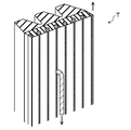
- FIG. 3 is a perspective view of a V-ribbed belt according to Embodiment 1.
- FIG. It is a figure which shows the pulley layout of the belt drive device for the auxiliary machinery drive of the motor vehicle using the V-ribbed belt which concerns on Embodiment 1.
- FIG. (A)-(c) is explanatory drawing which shows the manufacturing method of the V ribbed belt which concerns on Embodiment 1.
- FIG. 6 is a perspective view of a flat belt according to Embodiment 2.
- FIG. It is a figure which shows the pulley layout of the belt transmission apparatus using the flat belt which concerns on Embodiment 2.
- FIG. It is a perspective view of the test piece for a core wire peeling adhesion test. It is the figure which illustrated the test chart which measured the peeling adhesive force of the core wire. It is a figure which shows the pulley layout of a belt running test machine.
- FIG. 1 shows a V-ribbed belt B (power transmission belt) according to the first embodiment.
- the V-ribbed belt B according to the first embodiment is, for example, an endless belt used for an auxiliary machine driving belt transmission provided in an engine room of an automobile.
- the V-ribbed belt B according to Embodiment 1 has, for example, a belt length of 500 to 3000 mm, a belt width of 10 to 36 mm, and a belt thickness of 4.0 to 4.8 mm.
- the V-ribbed belt B includes a V-ribbed belt main body 10 configured in a double layer of an adhesive rubber layer 11 at an outer portion and a compressed rubber layer 12 at an inner portion.
- a reinforcing cloth 13 is stuck on the outer surface of the V-ribbed belt body 10.
- a core wire 14 is embedded in the adhesive rubber layer 11 so as to form a spiral having a pitch in the belt width direction.
- the adhesive rubber layer 11 is formed in a band shape having a horizontally long cross section, and has a thickness of 0.4 to 1.5 mm, for example.
- the adhesive rubber layer 11 is formed of a rubber composition crosslinked with sulfur by heating and pressurizing an uncrosslinked rubber composition in which a compounding agent is blended with a rubber component and kneaded.
- the rubber component of the rubber composition forming the adhesive rubber layer 11 is an ethylene- ⁇ -olefin elastomer.
- ethylene- ⁇ -olefin elastomers include ethylene- ⁇ -olefin copolymer rubber, ethylene- ⁇ -olefin-diene copolymer rubber, and the like. Specific examples include ethylene propylene diene monomer rubber. (EPDM), ethylene-propylene copolymer rubber (EPM), ethylene-butene copolymer rubber (EBM), ethylene-octene copolymer rubber (EOM) and the like.
- the ⁇ -olefin is preferably at least one selected from propylene, butene, hexene, and octene.
- ethylene- ⁇ -olefin-diene copolymer rubber is preferably used since it exhibits excellent heat resistance and cold resistance.
- the ethylene- ⁇ -olefin elastomer may be partially halogen-substituted.
- the rubber component a single type of ethylene- ⁇ -olefin elastomer may be used, or a plurality of types of ethylene- ⁇ -olefin elastomers may be blended.
- the rubber component may contain a rubber component other than the ethylene- ⁇ -olefin elastomer with a content of less than 50% by mass.
- the rubber composition that forms the adhesive rubber layer 11 contains sulfur and an ⁇ , ⁇ -unsaturated fatty acid metal salt as a compounding agent.
- compounding agents for example, carbon black, silica, organic reinforcing agent, vulcanization aid, vulcanization accelerator, anti-aging agent, silane coupling agent, and the like are blended.
- the amount of sulfur improves the adhesive strength between the adhesive rubber layer 11 and the core wire 14, and suppresses heat generation of the V-ribbed belt B during belt running, and peels off at the interface between the adhesive rubber layer 11 and the core wire 14. From the viewpoint of suppressing the above, it is preferably 2 parts by mass or more, more preferably 2.5 parts by mass or more with respect to 100 parts by mass of the rubber component. On the other hand, it is preferable that the compounding quantity of sulfur is 4 mass parts or less with respect to 100 mass parts of rubber components from the same viewpoint, and it is more preferable that it is 3.5 mass parts or less.
- ⁇ , ⁇ -unsaturated fatty acid metal salt is obtained by reacting ⁇ , ⁇ -unsaturated fatty acid with a metal oxide.
- the ⁇ , ⁇ -unsaturated fatty acid include ⁇ , ⁇ -monoethylenically unsaturated carboxylic acids such as methacrylic acid, acrylic acid, itaconic acid, and crotonic acid.
- the metal include zinc, magnesium, sodium, lithium, aluminum and the like, and zinc or magnesium which is a divalent metal is particularly preferable.
- Specific examples of the ⁇ , ⁇ -unsaturated fatty acid metal salt include zinc dimethacrylate, magnesium dimethacrylate, and zinc diacrylate.
- the ⁇ , ⁇ -unsaturated fatty acid metal salt a single species may be used, or a plurality of species may be used.
- the blending amount of the ⁇ , ⁇ -unsaturated fatty acid metal salt is 0.5 parts by mass or more with respect to 100 parts by mass of the rubber component from the viewpoint of improving the adhesive force between the adhesive rubber layer 11 and the core wire 14. Preferably, it is 1.0 part by mass or more.
- the blending amount of the ⁇ , ⁇ -unsaturated fatty acid metal salt is preferably 5.0 parts by mass or less, preferably 4.0 parts by mass or less, with respect to 100 parts by mass of the rubber component from the same viewpoint. Is more preferable.
- Examples of carbon black include furnace black (SAF, ISAF, N-339, HAF, N-351, MAF, FEF, SRF, GPF, ECF, N-234, etc.), thermal black (FT, MT, etc.), channel Examples thereof include black ((EPC, CC, etc.), acetylene black, etc. Carbon black may be used in a single kind or in a plurality of kinds.
- the adhesive force with the core wire 14 is improved, and the adhesive rubber layer 11 has a flexible rubber elasticity while having excellent bending resistance, whereby the core wire 14 jumps out of the adhesive rubber layer 11. From the viewpoint of preventing, it is preferably 10 parts by mass or more, more preferably 20 parts by mass or more with respect to 100 parts by mass of the rubber component. Masui.
- the amount of carbon black is preferably not more than 60 parts by mass with respect to 100 parts by mass of the rubber component, more preferably not more than 55 parts by mass.
- silica examples include those obtained by various production methods such as a sol-gel method, a wet method, and a dry method.
- silica produced by a wet method is preferable from the viewpoints of the reinforcing effect, low heat build-up, and wet friction characteristics.
- the microstructure of silica is not particularly limited, but the BET adsorption specific surface area is preferably 50 to 200 cm 2 / g in order to enhance the interaction with rubber molecules.
- the compounding amount of silica is preferably 20 parts by mass or more and more preferably 30 parts by mass or more with respect to 100 parts by mass of the rubber component.
- the amount of silica is preferably 100 parts by mass or less and more preferably 90 parts by mass or less with respect to 100 parts by mass of the rubber component.
- the compounding amount of silica is preferably 75% by mass or more, more preferably 80% by mass or more with respect to the compounding amount of carbon black.
- the compounding amount of silica is preferably 1000% by mass or less and more preferably 900% by mass or less with respect to the compounding amount of carbon black.
- the total amount of silica and carbon black is preferably 70 parts by mass or more and more preferably 75 parts by mass or more with respect to 100 parts by mass of the rubber component.
- the total amount of silica and carbon black is preferably 100 parts by mass or less and more preferably 90 parts by mass or less with respect to 100 parts by mass of the rubber component.
- organic reinforcing agent examples include phenol resin, high styrene resin, coumarone indene resin, amino resin, vinyl toluene resin, lignin resin, butylphenol acetylene resin, and xylene formaldehyde resin.
- the adhesive force between the adhesive rubber layer 11 and the core wire 14 can be further improved, and peeling at the interface between the adhesive rubber layer 11 and the core wire 14 can be suppressed to improve the durability of the V-ribbed belt B. From the viewpoint that the improvement effect becomes more remarkable, thermosetting phenol resin and melamine resin are preferable.
- a single type of organic reinforcing agent may be used, or a plurality of types may be used.
- the amount of the organic reinforcing agent blended is 0.5 to 100 parts by mass with respect to 100 parts by mass of the rubber component from the viewpoint that the adhesive rubber layer 11 has excellent wear resistance and flex resistance and has flexible rubber elasticity. It is preferably 3.0 parts by mass.
- the vulcanization aid examples include metal oxides such as magnesium oxide and zinc oxide, fatty acids such as metal carbonates and stearic acid, and derivatives thereof.
- a single type of vulcanization aid may be used, or a plurality of types may be used.
- the blending amount of the vulcanization aid is preferably 3.0 to 10 parts by mass with respect to 100 parts by mass of the rubber component.
- the rubber composition forming the adhesive rubber layer 11 preferably has a complex elastic modulus at 120 ° C. of 20 MPa or more from the viewpoint of suppressing the core wire 14 from jumping out of the adhesive rubber layer 11.
- the rubber composition forming the adhesive rubber layer 11 preferably has a complex elastic modulus at 120 ° C. of 30 MPa or less from the same viewpoint.
- the compression rubber layer 12 is provided so that a plurality of V ribs 15 constituting a pulley contact portion hang down inward.
- the plurality of V ribs 15 are each formed in a ridge having a substantially inverted triangular cross section extending in the circumferential direction, and provided in parallel in the belt width direction.
- Each V-rib 15 is formed, for example, with a rib height of 1.5 to 2.5 mm and a width between the base ends of 2.3 to 4.7 mm.
- the number of ribs is, for example, 3 to 10 (6 in FIG. 1).
- the compressed rubber layer 12 is formed of a rubber composition in which various compounding agents are blended with a rubber component.
- the rubber component include ethylene propylene diene monomer rubber (EPDM), chloroprene rubber (CR), hydrogenated nitrile rubber (H-NBR), and the like.
- the compounding agent include a crosslinking agent, a vulcanization aid, a vulcanization accelerator, an anti-aging agent, a plasticizer, a reinforcing material, a filler, a short fiber, and hollow particles.
- the rubber composition forming the compressed rubber layer 12 is obtained by crosslinking a non-crosslinked rubber composition obtained by blending a rubber component with a compounding agent and then kneading. This rubber composition may be crosslinked with sulfur as a crosslinking agent, or may be crosslinked with an organic peroxide as a crosslinking agent.
- Short rubber 16 such as nylon short fiber may be blended in the rubber composition forming the compressed rubber layer 12.
- the short fibers 16 are preferably included in the compressed rubber layer 12 so as to be oriented in the belt width direction, and the short fibers 16 are provided so as to protrude from the surface of the compressed rubber layer 12. Is preferred.
- the structure which made the short fiber 16 adhere to the surface of the compression rubber layer 12 instead of the structure which mix
- the reinforcing cloth 13 is composed of a woven cloth such as plain weave made of warp and weft such as polyester fiber and cotton.
- a process of immersing in a resorcin / formalin / latex aqueous solution (hereinafter referred to as “RFL aqueous solution”) and heating and heating the V-ribbed belt main body 10.
- RRL aqueous solution resorcin / formalin / latex aqueous solution
- Adhesion treatment is applied to the surface to be coated with rubber paste and dried.
- the reinforcing cloth 13 has a thickness of 0.5 to 2.0 mm, for example.
- the core wire 14 is arranged so as to form a spiral having a pitch in the belt width direction, and the pitch of the spiral is, for example, 0.6 to 1.5 mm.
- the core wire 14 is formed of a fiber material.
- the fiber material forming the core 14 include polyethylene terephthalate (PET) fiber, polyvinyl alcohol fiber (PVA), polyethylene naphthalate (PEN) fiber, para-aramid fiber, meta-aramid fiber, and 4,6 nylon fiber. 6, 6 nylon fiber, carbon fiber, glass fiber and the like.
- the core 14 may be composed of a single type of fiber material, or may be composed of a mixture of a plurality of types of fiber materials.
- the fineness of the fiber material constituting the core wire 14 is, for example, 200 to 5000 dtex, and the filament diameter is, for example, 0.003 to 0.030 mm.
- the total fineness of the fiber material constituting the core wire 14 is, for example, 2000 to 18000 dtex.
- the outer diameter of the core wire 14 is 0.4 to 2.2 mm or more, for example.
- Examples of the yarn configuration of the core wire 14 include a single twisted yarn, various twisted yarns, a Lang twisted yarn, and a braided string. Of these, single twisted yarns and various twisted yarns are preferable.
- the number of twists is, for example, 2 to 60 T / 10 cm.
- the core wire 14 of the single twisted yarn may be an S twisted yarn or a Z twisted yarn, and both the S twisted yarn and the Z twisted yarn may be provided so as to form a double helix.
- the fineness of the lower twisted yarn is, for example, 600 to 5000 dtex.
- the number of lower twists is, for example, 2 to 60 T / 10 cm.
- the number of lower twisted yarns is, for example, 2 to 20.
- the number of upper twists is, for example, 2T / 10 cm or more.
- the core wire 14 of the plied yarn may be an S twist yarn whose upper twist is an S twist, or may be a Z twist yarn whose upper twist is a Z twist, and further, both an S twist yarn and a Z twist yarn. You may provide so that a double helix may be formed.
- the core wire 14 is dipped in an RFL aqueous solution and then heated and / or dipped in rubber paste and then dried. Adhesive treatment is applied.
- the RFL aqueous solution used in the adhesion treatment is a mixture of latex and an initial condensate of resorcin and formaldehyde.
- the latex include vinylpyridine styrene butadiene rubber latex (Vp ⁇ SBR), chloroprene rubber latex (CR), chlorosulfonated polyethylene rubber latex (CSM), and the like.
- Vp ⁇ SBR vinylpyridine styrene butadiene rubber latex
- CR chloroprene rubber latex
- CSM chlorosulfonated polyethylene rubber latex
- a single type of latex may be used, or a plurality of types may be used.
- the mass ratio of the initial condensate (RF) of resorcin and formaldehyde to latex (L) is, for
- the rubber paste used in the adhesion treatment is obtained by dissolving an uncrosslinked rubber composition in a solvent such as toluene.
- a solvent such as toluene.
- the uncrosslinked rubber composition contained in the rubber paste include an uncrosslinked rubber composition before the formation of the adhesive rubber layer 11. Therefore, in the uncrosslinked rubber composition contained in the rubber paste, the rubber component may be an ethylene- ⁇ -olefin elastomer and an ⁇ , ⁇ -unsaturated fatty acid metal salt may be blended.
- the core wire 14 is immersed in a base treatment agent in which epoxy or isocyanate (block isocyanate) is dissolved in a solvent such as toluene or dispersed in water before the adhesion treatment with the RFL aqueous solution and / or rubber paste. It is preferable that an adhesive treatment for heating is performed.
- a base treatment agent in which epoxy or isocyanate (block isocyanate) is dissolved in a solvent such as toluene or dispersed in water before the adhesion treatment with the RFL aqueous solution and / or rubber paste. It is preferable that an adhesive treatment for heating is performed.
- the rigidity in the belt length direction becomes too high, and particularly in a small pulley.
- durability is likely to deteriorate because the restoring force of the adhesive rubber layer is large.
- the tensile stress at 10% elongation in the belt length direction at 125 ° C. of the rubber composition forming the adhesive rubber layer is 1.1 to 1.7 MPa. In this case, the durability tends to be lowered particularly when the transmission belt is wound around a pulley with high tension.
- the adhesive rubber layer 11 with which the core wire 14 contacts the V-ribbed belt main body 10 includes an ethylene- ⁇ -olefin elastomer as a rubber component, and the rubber component. Is formed of a rubber composition that is blended with ⁇ , ⁇ -unsaturated fatty acid metal salt and crosslinked with sulfur, so that the adhesive force between the core wire 14 and the V-ribbed belt body 10 can be improved. Therefore, it is possible to suppress the core wire 14 from being peeled off from the rubber composition forming the adhesive rubber layer. As a result, the core wire 14 is wound around a pulley with high tension or wound around a small-diameter pulley. Sufficient durability can be obtained.
- FIG. 2 shows a pulley layout of an auxiliary drive belt transmission device 20 for an automobile using the V-ribbed belt B according to the first embodiment.
- the accessory drive belt transmission device 20 is of a serpentine drive type in which a V-ribbed belt B is wound around six pulleys of four rib pulleys and two flat pulleys to transmit power.
- the accessory drive belt transmission 20 includes a power steering pulley 21 at the uppermost position, an AC generator pulley 22 disposed slightly diagonally to the right of the power steering pulley 21, and diagonally to the left of the power steering pulley 21.
- a flat pulley tensioner pulley 23 disposed diagonally to the left of the generator pulley 22; a flat water pump pulley 24 disposed diagonally to the left of the AC generator pulley 22 and directly below the tensioner pulley 23; and a tensioner pulley 23 and a crankshaft pulley 25 disposed diagonally to the left of the water pump pulley 24 and an air conditioner pulley 26 disposed diagonally to the right of the water pump pulley 24 and the crankshaft pulley 25.
- rib pulleys all except the tensioner pulley 23 and the water pump pulley 24 which are flat pulleys are rib pulleys.
- These rib pulleys and flat pulleys are made of, for example, a metal press-worked product, a casting, a resin molded product such as nylon resin, phenol resin, and the diameter of the pulley is 50 to 150 mm.
- the adhesive rubber layer 11 with which the core wire 14 of the V-ribbed belt main body 10 of the V-ribbed belt B contacts is made of an ethylene- ⁇ -olefin elastomer.
- ⁇ , ⁇ -unsaturated fatty acid metal salt is blended with the rubber component and formed with a rubber composition crosslinked with sulfur, so it is used by being wound around a pulley with high tension. However, even if the diameter of the pulley is reduced, sufficient durability can be obtained.
- each compound is first blended with the raw rubber and kneaded with a kneader such as a kneader or a Banbury mixer, and the resulting uncrosslinked rubber composition is formed into a sheet by calendar molding or the like.
- a kneader such as a kneader or a Banbury mixer
- an uncrosslinked rubber sheet 11 ′ uncrosslinked rubber composition for forming a belt
- an uncrosslinked rubber sheet 12 'for the compressed rubber layer 12 is also produced.
- the short rubber 16 is included in the compressed rubber layer 12 so as to be oriented in the belt width direction
- the sheet-shaped product is cut into a predetermined length, and the short fibers 16 are oriented in the width direction.
- the uncrosslinked rubber sheet 12 ′ may be formed by connecting as described above. Further, the woven fabric 13 ′ to be the reinforcing fabric 13 is subjected to a treatment of immersing in an RFL aqueous solution and heating, and an adhesive treatment of coating and drying the rubber paste on the surface on the V-ribbed belt main body 10 side, and joining both ends. To form a cylinder. Moreover, after performing the adhesion process which immerses and heats the twisted yarn 14 'used as the core wire 14 in each of the base treatment agent and the RFL aqueous solution, the adhesion process of immersing in rubber paste and drying by heating is performed.
- the outer peripheral portion of the adhesive rubber layer 11 is formed on the outer periphery of the cylindrical inner mold 30 after covering the outer periphery of the woven fabric 13 'serving as the reinforcing cloth 13.
- the uncrosslinked rubber sheet 11 ′ is wound, and then an adhesive-treated twisted yarn 14 ′ that becomes the core wire 14 is spirally wound thereon, and then an inner portion of the adhesive rubber layer 11 is formed thereon.
- An uncrosslinked rubber sheet 11 ' is wound, and further an uncrosslinked rubber sheet 12' for forming the compressed rubber layer 12 is wound thereon.
- the molded body on the inner mold 30 is covered with a rubber sleeve and set in a molding pot, and the inner mold 30 is heated with high-temperature steam and the like, and the rubber sleeve is radially inward by applying high pressure. Press on. At this time, the rubber component flows and the cross-linking reaction proceeds. In addition, the adhesion reaction of the twisted yarn 14 ′ to the rubber also proceeds to form a composite as shown in FIG. As a result, a cylindrical belt slab B '(belt body preform) is formed.
- the V-ribbed belt B is obtained by cutting the belt slab B ', which is divided and formed with the V-ribs 15 on the outer circumference, into a predetermined width and turning each side upside down.
- FIG. 4 shows a flat belt C according to the second embodiment.
- the flat belt C according to the second embodiment is, for example, an endless belt used for a drive transmission application or a conveyance application of a blower, a compressor, or a generator.
- the flat belt C according to the second embodiment has a belt length of 600 to 3000 mm, a belt width of 10 to 100 mm, and a belt thickness of 1.0 to 5.0 mm, for example.
- an endless flat belt body is formed by laminating a belt-like adhesive rubber portion (core wire embedded portion) 41a outside the belt and a belt-like bottom rubber portion 41b inside the belt. It is configured. Further, in this flat belt C, a core wire 42 is embedded in the center of the adhesive rubber portion 41a in the thickness direction so as to form a spiral with a constant pitch in the belt width direction. Further, the flat belt C is coated with a reinforcing cloth 43 on the outer surface of the belt.
- the adhesive rubber portion 41a is formed in a band shape having a horizontally long cross section, and has a thickness of 0.4 to 1.5 mm, for example.
- the adhesive rubber portion 41a is formed of a rubber composition in which various compounding agents are blended with a rubber component, and the composition thereof is the same as that of the adhesive rubber layer 11 of the first embodiment.
- the bottom rubber portion 41b is formed in a strip shape having a horizontally long cross section, and has a thickness of 0.5 to 2.0 mm, for example.
- the bottom rubber portion 41b is formed of a rubber composition in which various compounding agents are blended with a rubber component.
- the rubber component include ethylene propylene diene monomer rubber (EPDM), chloroprene rubber (CR), hydrogenated nitrile rubber (H-NBR) and the like, as in the case of the compressed rubber layer 12 of the first embodiment.
- the compounding agent for example, a crosslinking agent, a vulcanization aid, a vulcanization accelerator, an anti-aging agent, a plasticizer, a reinforcing material, a filler, a short fiber, and a hollow Particles and the like.
- the rubber composition forming the bottom rubber portion 41b is obtained by crosslinking an uncrosslinked rubber composition kneaded by blending a rubber component with a compounding agent by heating and pressing.
- This rubber composition may be crosslinked with sulfur as a crosslinking agent, or may be crosslinked with an organic peroxide as a crosslinking agent.
- the core wire 42 is the same as in the first embodiment, for example, polyethylene terephthalate (PET) fiber, polyvinyl alcohol fiber (PVA), polyethylene naphthalate (PEN) fiber, para-aramid fiber, meta-aramid fiber, 4,6 nylon fiber. , 6,6 nylon fibers, carbon fibers, or glass fibers are formed by applying an adhesive treatment with an RFL aqueous solution or the like before molding processing.
- PET polyethylene terephthalate
- PVA polyvinyl alcohol fiber
- PEN polyethylene naphthalate
- para-aramid fiber para-aramid fiber
- meta-aramid fiber 4,6 nylon fiber.
- 6,6 nylon fibers, carbon fibers, or glass fibers are formed by applying an adhesive treatment with an RFL aqueous solution or the like before molding processing.
- the core wire 42 has an outer diameter of 0.4 to 2.2 mm and a pitch in the belt width direction is 1.2 to 2 times the outer diameter.
- the reinforcing cloth 43 is composed of a woven cloth such as a plain weave made of warp and weft such as polyester fiber and cotton.
- the reinforcing cloth 43 is subjected to a treatment of dipping in an RFL aqueous solution and heating before molding, and a treatment of coating the surface on the flat belt C side with a rubber paste and drying.
- the reinforcing cloth 43 has a thickness of 0.5 to 2.0 mm, for example.
- the flat belt C having the above configuration can be manufactured by a known manufacturing method.
- FIG. 5 shows a pulley layout of the belt transmission device 50 using the flat belt C according to the second embodiment.
- the belt transmission device 50 has a configuration in which the flat belt C is wound around a pair of flat pulleys of a driving pulley 51 and a driven pulley 52 to transmit power.
- the pulley diameter of the driving pulley 51 is, for example, 50 to 200 mm
- the pulley diameter of the driven pulley 52 is, for example, 50 to 200 mm.
- the V-ribbed belt B and the flat belt C are examples of transmission belts.
- the belt is not particularly limited thereto, and may be a V belt, a toothed belt, or the like.
- V-ribbed belt V-ribbed belts of Examples 1 to 12 and Comparative Examples 1 to 12 below were produced. Each characteristic configuration is also shown in Tables 1 to 3.
- Example 1 A V-ribbed belt of Example 1 was produced by the same method as in Embodiment 1 above. Specifically, in the V-ribbed belt of Example 1, the rubber component is ethylene propylene diene monomer rubber (EPDM) (trade name: EP22 manufactured by JSR Corporation), and silica (Evonik Degussa) is added to 100 parts by mass of the rubber component. Japan Corporation, trade name: Ultra Jill VN3, BET specific surface area of 175cm 2 / g) 40 parts by weight, FEF carbon black (manufactured by Tokai carbon Co., Ltd.
- EPDM ethylene propylene diene monomer rubber
- silica Evonik Degussa
- the compressed rubber layer was formed of a rubber composition in which nylon short fibers and sulfur were blended with ethylene propylene diene monomer rubber (EPDM).
- EPDM ethylene propylene diene monomer rubber
- the core wire is heated after being immersed in an RFL aqueous solution in which a latex is mixed with an initial condensate of resorcinol and formaldehyde before being processed into a twisted yarn formed of para-aramid fiber (trade name: Technora manufactured by Teijin Limited). It is composed of an adhesive treatment.
- the reinforcing cloth is made of rubberized canvas.
- the V-ribbed belt of Example 1 had a belt circumference of 1180 mm, a belt thickness of 4.0 mm, a V-rib height of 2.0 mm, and three ribs (belt width of 10.68 mm).
- Example 2 A V-ribbed belt having the same configuration as in Example 1 was prepared except that the amount of silica in the uncrosslinked rubber composition forming the adhesive rubber layer was 30 parts by mass with respect to 100 parts by mass of the EPDM polymer, and this was carried out. Example 2 was adopted. Therefore, the blending amount of silica is 75% by mass with respect to the blending amount of carbon black. The total amount of FEF carbon black and silica is 70 parts by mass with respect to 100 parts by mass of the rubber component.
- Example 3 The amount of silica in the uncrosslinked rubber composition forming the adhesive rubber layer was 45 parts by mass with respect to 100 parts by mass of the EPDM polymer, and the amount of carbon black was 55 parts by mass with respect to 100 parts by mass of the EPDM polymer.
- a V-ribbed belt having the same configuration as in Example 1 was prepared, and this was taken as Example 3. Therefore, the amount of silica is 82% by mass with respect to the amount of carbon black.
- the total amount of FEF carbon black and silica is 100 parts by mass with respect to 100 parts by mass of the rubber component.
- Example 4 The amount of silica in the uncrosslinked rubber composition forming the adhesive rubber layer was 60 parts by mass with respect to 100 parts by mass of the EPDM polymer, and the amount of carbon black was 40 parts by mass with respect to 100 parts by mass of the EPDM polymer.
- a V-ribbed belt having the same configuration as in Example 1 was prepared, and this was designated as Example 4. Therefore, the compounding amount of silica is 150% by mass with respect to the compounding amount of carbon black.
- the total amount of FEF carbon black and silica is 100 parts by mass with respect to 100 parts by mass of the rubber component.
- Example 5 The amount of silica in the uncrosslinked rubber composition forming the adhesive rubber layer was 50 parts by mass with respect to 100 parts by mass of the EPDM polymer, and the amount of carbon black was 30 parts by mass with respect to 100 parts by mass of the EPDM polymer.
- a V-ribbed belt having the same configuration as in Example 1 was prepared, and this was designated as Example 5. Therefore, the compounding amount of silica is 167% by mass with respect to the compounding amount of carbon black.
- the total amount of FEF carbon black and silica is 80 parts by mass with respect to 100 parts by mass of the rubber component.
- Example 6 The amount of silica in the uncrosslinked rubber composition forming the adhesive rubber layer was 60 parts by mass with respect to 100 parts by mass of the EPDM polymer, and the amount of carbon black was 10 parts by mass with respect to 100 parts by mass of the EPDM polymer.
- a V-ribbed belt having the same configuration as in Example 1 was prepared, and this was designated as Example 6. Therefore, the compounding amount of silica is 600% by mass with respect to the compounding amount of carbon black.
- the total amount of FEF carbon black and silica is 70 parts by mass with respect to 100 parts by mass of the rubber component.
- Example 7 The amount of silica in the uncrosslinked rubber composition forming the adhesive rubber layer was 90 parts by mass with respect to 100 parts by mass of the EPDM polymer, and the amount of carbon black was 10 parts by mass with respect to 100 parts by mass of the EPDM polymer.
- a V-ribbed belt having the same configuration as in Example 1 was prepared, and this was designated as Example 7. Therefore, the compounding amount of silica is 900 mass% with respect to the compounding amount of carbon black.
- the total amount of FEF carbon black and silica is 100 parts by mass with respect to 100 parts by mass of the rubber component.
- Example 8 A V-ribbed belt having the same configuration as in Example 1 was prepared, except that the amount of zinc dimethacrylate in the uncrosslinked rubber composition forming the adhesive rubber layer was 0.5 parts by mass with respect to 100 parts by mass of the EPDM polymer. This was designated as Example 8. Therefore, the compounding quantity of silica is 100 mass% with respect to the compounding quantity of carbon black. The total amount of FEF carbon black and silica is 80 parts by mass with respect to 100 parts by mass of the rubber component.
- Example 9 A V-ribbed belt having the same configuration as in Example 1 was prepared except that the amount of zinc dimethacrylate of the uncrosslinked rubber composition forming the adhesive rubber layer was 3 parts by mass with respect to 100 parts by mass of the EPDM polymer, This was designated as Example 9. Therefore, the compounding quantity of silica is 100 mass% with respect to the compounding quantity of carbon black. The total amount of FEF carbon black and silica is 80 parts by mass with respect to 100 parts by mass of the rubber component.
- Example 10 A V-ribbed belt having the same configuration as in Example 1 was prepared except that the amount of zinc dimethacrylate in the uncrosslinked rubber composition forming the adhesive rubber layer was 5 parts by mass with respect to 100 parts by mass of the EPDM polymer, This was designated Example 10. Therefore, the compounding quantity of silica is 100 mass% with respect to the compounding quantity of carbon black. The total amount of FEF carbon black and silica is 80 parts by mass with respect to 100 parts by mass of the rubber component.
- Example 11 A V-ribbed belt having the same configuration as that of Example 1 was prepared except that the amount of sulfur in the uncrosslinked rubber composition forming the adhesive rubber layer was 2 parts by mass with respect to 100 parts by mass of the EPDM polymer. Example 11 was used. Therefore, the compounding quantity of silica is 100 mass% with respect to the compounding quantity of carbon black. The total amount of FEF carbon black and silica is 80 parts by mass with respect to 100 parts by mass of the rubber component.
- Example 12 A V-ribbed belt having the same configuration as in Example 1 was prepared except that the amount of sulfur in the uncrosslinked rubber composition forming the adhesive rubber layer was 4 parts by mass with respect to 100 parts by mass of the EPDM polymer, and this was carried out. Example 12 was adopted. Therefore, the compounding quantity of silica is 100 mass% with respect to the compounding quantity of carbon black. The total amount of FEF carbon black and silica is 80 parts by mass with respect to 100 parts by mass of the rubber component.
- the amount of silica in the uncrosslinked rubber composition forming the adhesive rubber layer is 20 parts by mass with respect to 100 parts by mass of the EPDM polymer
- the amount of carbon black is 60 parts by mass with respect to 100 parts by mass of the EPDM polymer
- a V-ribbed belt having the same configuration as in Example 1 was prepared except that the blending amount of zinc methacrylate was 0 parts by mass with respect to 100 parts by mass of the EPDM polymer. Therefore, the amount of silica is 33% by mass with respect to the amount of carbon black.
- the total amount of FEF carbon black and silica is 80 parts by mass with respect to 100 parts by mass of the rubber component.
- Example 2 A V-ribbed belt having the same configuration as in Example 1 was prepared except that the amount of zinc dimethacrylate in the uncrosslinked rubber composition forming the adhesive rubber layer was 0 parts by mass with respect to 100 parts by mass of the EPDM polymer, This was designated as Comparative Example 2. Therefore, the compounding quantity of silica is 100 mass% with respect to the compounding quantity of carbon black. The total amount of FEF carbon black and silica is 80 parts by mass with respect to 100 parts by mass of the rubber component.
- ⁇ Comparative example 4> The amount of silica in the uncrosslinked rubber composition forming the adhesive rubber layer was 30 parts by mass with respect to 100 parts by mass of the EPDM polymer, and the amount of carbon black was 70 parts by mass with respect to 100 parts by mass of the EPDM polymer.
- a V-ribbed belt having the same configuration as in Example 1 was prepared, and this was designated as Comparative Example 4. Therefore, the compounding quantity of silica is 43 mass% with respect to the compounding quantity of carbon black.
- the total amount of FEF carbon black and silica is 100 parts by mass with respect to 100 parts by mass of the rubber component.
- ⁇ Comparative Example 7> The amount of silica in the uncrosslinked rubber composition forming the adhesive rubber layer was 60 parts by mass with respect to 100 parts by mass of the EPDM polymer, and the amount of carbon black was 60 parts by mass with respect to 100 parts by mass of the EPDM polymer.
- a V-ribbed belt having the same configuration as in Example 1 was prepared, and this was designated as Comparative Example 7. Therefore, the compounding quantity of silica is 100 mass% with respect to the compounding quantity of carbon black.
- the total amount of FEF carbon black and silica is 120 parts by mass with respect to 100 parts by mass of the rubber component.
- ⁇ Comparative Example 8> The amount of silica in the uncrosslinked rubber composition forming the adhesive rubber layer was 80 parts by mass with respect to 100 parts by mass of the EPDM polymer, and the amount of carbon black was 40 parts by mass with respect to 100 parts by mass of the EPDM polymer. A V-ribbed belt having the same configuration as in Example 1 was prepared, and this was designated as Comparative Example 8. Therefore, the compounding amount of silica is 200% by mass with respect to the compounding amount of carbon black. The total amount of FEF carbon black and silica is 120 parts by mass with respect to 100 parts by mass of the rubber component.
- Example 10 A V-ribbed belt having the same configuration as in Example 1 was prepared except that the amount of zinc dimethacrylate of the uncrosslinked rubber composition forming the adhesive rubber layer was 7 parts by mass with respect to 100 parts by mass of the EPDM polymer, This was designated as Comparative Example 10. Therefore, the compounding quantity of silica is 100 mass% with respect to the compounding quantity of carbon black. The total amount of FEF carbon black and silica is 80 parts by mass with respect to 100 parts by mass of the rubber component.
- Example 11 A V-ribbed belt having the same configuration as in Example 1 was prepared except that the amount of sulfur in the uncrosslinked rubber composition forming the adhesive rubber layer was 1 part by mass with respect to 100 parts by mass of the EPDM polymer, and this was compared. Example 11 was used. Therefore, the compounding quantity of silica is 100 mass% with respect to the compounding quantity of carbon black. The total amount of FEF carbon black and silica is 80 parts by mass with respect to 100 parts by mass of the rubber component.
- Example 12 A V-ribbed belt having the same structure as in Example 1 was prepared except that the amount of sulfur in the uncrosslinked rubber composition forming the adhesive rubber layer was 5 parts by mass with respect to 100 parts by mass of the EPDM polymer, and this was compared. Example 12 was adopted. Therefore, the compounding quantity of silica is 100 mass% with respect to the compounding quantity of carbon black. The total amount of FEF carbon black and silica is 80 parts by mass with respect to 100 parts by mass of the rubber component.
- Example 1 was set to 1.00, and the relative values of the adhesive strengths of Examples 1 to 12 and Comparative Examples 2 to 12 were calculated.
- a test chart is obtained as shown in FIG. 7. Among these, five peak values are selected from the lowest, and the average value thereof is taken as the peel adhesive strength. Further, two test pieces T were tested with each belt, and the data with the lower peel adhesion was adopted as the data.
- FIG. 8 shows a belt running test machine 60 for durability test on a V-ribbed belt.
- This belt running test machine 60 is provided with a drive pulley 61 that is a ribbed pulley having a pulley diameter of 120 mm, an idler pulley 62 that is a flat pulley having a pulley diameter of 85 mm provided on the left and a diagonally upper right side of the idler pulley 62.
- a first driven pulley 63 which is a ribbed pulley having a pulley diameter of 120 mm
- a tension pulley 64 which is a ribbed pulley having a pulley diameter of 45 mm, which is provided diagonally right above the drive pulley 61 and diagonally below right of the first driven pulley 63. I have.
- the V-ribbed belt B is wound around the idler pulley 62 so that the belt winding angle ( ⁇ 1 ) becomes 120 degrees and the tension pulley 64 so that the belt winding angle ( ⁇ 2 ) becomes 90 degrees.
- the tension pulley 64 is configured so as to be able to apply a belt load to the wound V-ribbed belt B so as to be movable left and right and to the right by a constant dead weight DW.
- the V-rib 15 of the compression rubber layer 12 contacts the driving pulley 61, the driven pulley 63, and the tension pulley 64 of the belt running test machine 60.
- the tension pulley 61 was loaded with a dead weight DW of 9.06 N to the right.
- the drive pulley 61 was rotated at a rotational speed of 4900 rpm to run the V-ribbed belt. And the state of the location where the defect first occurred in the belt was recorded.
- the first defect in the belt run until the fault around the core, and measure the running time from the start of the belt until the fault occurs around the core, and compare The travel time of Example 1 was set to 1.00, and the relative value of each travel time was calculated.
- Test evaluation results The test evaluation results are shown in Tables 4-6.
- the complex elastic modulus at 120 ° C. of the adhesive rubber layer is 22.87 MPa in Example 1, 20.46 MPa in Example 2, 26.98 NPa in Example 3, 27.58 MPa in Example 4, and 23.58 in Example 5.
- 12 MPa, Example 6 22.75 MPa, Example 7 29.71 MPa, Example 8 23.21 MPa, Example 9 21.73 MPa, Example 10 20.70 MPa, Example 11 21.10 MPa, And Example 12 was 25.39 MPa
- Comparative Example 1 was 22.81 MPa
- Comparative Example 2 was 23.86 MPa
- Comparative Example 3 was 19.15 MPa
- Comparative Example 4 was 25.77 MPa
- Comparative Example 5 was 33.20 MPa
- Comparative Example 6 is 26.98 MPa
- Comparative Example 7 is 35.31 MPa
- Comparative Example 8 is 37.12 MPa
- Comparative Example 9 is 18.15 MPa
- Comparative Example 10 is 1 .52MPa
- the adhesive strength of the core wire is 1.58 in Example 1, 1.45 in Example 2, 1.40 NPa in Example 3 and 1.40 in Example 4 when the adhesive strength in Comparative Example 1 is 1.00. 49, Example 5 is 1.67, Example 6 is 1.71, Example 7 is 1.68, Example 8 is 1.40, Example 9 is 1.79, Example 10 is 1.95, Example 11 is 1.44, and Example 12 is 1.63, and Comparative Example 2 is 1.15, Comparative Example 3 is 1.35, Comparative Example 4 is 1.32, Comparative Example 5 is 1.64, And Comparative Example 6 is 1.65, Comparative Example 7 is 1.33, Comparative Example 8 is 1.38, Comparative Example 9 is 1.40, Comparative Example 10 is 1.19, Comparative Example 11 is 1.25, and The comparative example 12 was 1.67.
- Example 3 is 2.11 NPa
- Example 4 is 2.49
- Example 5 is 2.67
- Example 6 is 2.42
- Example 7 is 2.03
- Example 8 is 2.08,
- Example 9 was 2.75
- Example 10 was 2.50
- Example 11 was 2.11
- Example 12 was 2.39
- Comparative Example 2 was 1.10
- Comparative Example 3 was 1.49
- Comparative Example 4 is 1.31
- Comparative Example 5 is 1.68
- Comparative Example 6 is 1.79
- Comparative Example 7 is 1.59
- Comparative Example 8 is 1.63
- Comparative Example 9 is 1.29
- Comparative Example 10 was 1.91
- Comparative Example 11 was 1.85
- Comparative Example 12 was 1.93.
- the present invention is useful for a transmission belt.
- V-ribbed belt (power transmission belt) B 'Belt Slab C Flat Belt (Power Transmission Belt) T Test piece 10 V-ribbed belt main body 11 Adhesive rubber layer 11 ′, 12 ′ Uncrosslinked rubber sheet 12 Compressed rubber layer 13 Reinforcement fabric 13 woven fabric 14 Core wire 14 ′ Thread 15 V Rib 16 Short fiber 20 Auxiliary drive belt transmission 21 Power steering pulley 22 AC generator pulley 23 Tensioner pulley 24 Water pump pulley 25 Crankshaft pulley 26 Air conditioner pulley 30 Inner die 41a Adhesive rubber portion 41b Bottom rubber portion 42 Core wire 43 Reinforcement cloth 50 Belt transmission device 51 Drive pulley 52 Drive pulley 60 belt running test machine 61 tension pulley 61 drive pulley 62 idler pulley 63 driven pulley 64 tension pulley
Landscapes
- Engineering & Computer Science (AREA)
- General Engineering & Computer Science (AREA)
- Mechanical Engineering (AREA)
- Textile Engineering (AREA)
- Compositions Of Macromolecular Compounds (AREA)
Abstract
Description
図1は、実施形態1に係るVリブドベルトB(伝動ベルト)を示す。この実施形態1に係るVリブドベルトBは、例えば、自動車のエンジンルーム内に設けられる補機駆動用のベルト伝動装置等に用いられるエンドレスのものである。実施形態1に係るVリブドベルトBは、例えば、ベルト長さが500~3000mm、ベルト幅が10~36mm、及びベルト厚さが4.0~4.8mmである。
図4は、実施形態2に係る平ベルトCを示す。
上記実施形態1及び2では、VリブドベルトB及び平ベルトCを伝動ベルトの例としたが、特にこれに限定されるものではなく、Vベルト、歯付ベルト等であってもよい。
以下の実施例1~12及び比較例1~12のVリブドベルトを作製した。それぞれの特徴的構成については表1~3にも示す。
上記実施形態1と同一の方法により実施例1のVリブドベルトを作製した。具体的には、この実施例1のVリブドベルトでは、ゴム成分をエチレンプロピレンジエンモノマーゴム(EPDM)(JSR社製 商品名:EP22)とし、そのゴム成分100質量部に対して、シリカ(エボニックデグサジャパン社製 商品名:ウルトラジルVN3、BET比表面積が175cm2/g)40質量部、FEFカーボンブラック(東海カーボン社製 商品名:シーストSO、DBP吸油量115cm3/100g)40質量部、オイル(日本サン石油社製 商品名:SUNPAR2280)15質量部、ステアリン酸(日本油脂社製 商品名:ステアリン酸つばき)1質量部、酸化亜鉛(堺化学工業社製 商品名:酸化亜鉛3種)5質量部、ジメタクリル酸亜鉛(川口化学社製 商品面:アクターZMA)2質量部、フェノール樹脂(住友ベークライト社製 商品名:スミライトレジンPR12687)1.5質量部、硫黄(日本乾溜工業社製 商品名:セイミOT)3質量部、チアゾール系加硫促進剤(大内新興化学工業社製 商品名:ノクセラーDM)1質量部、及びチウラム系加硫促進剤加硫促進材(大内新興化学工業社製 商品名:ノクセラーTBT)2質量部を配合して密閉式混練機で混練したものをカレンダーロールで圧延したシート状の未架橋ゴム組成物を用いて接着ゴム層を形成した。従って、シリカの配合量は、カーボンブラックの配合量に対して100質量%である。また、FEFカーボンブラック及びシリカの合計配合量は、ゴム成分100質量部に対して80質量部である。
接着ゴム層を形成する未架橋ゴム組成物のシリカの配合量をEPDMポリマー100質量部に対して30質量部としたことを除いて実施例1と同一構成のVリブドベルトを作製し、これを実施例2とした。従って、シリカの配合量は、カーボンブラックの配合量に対して75質量%である。また、FEFカーボンブラック及びシリカの合計配合量は、ゴム成分100質量部に対して70質量部である。
接着ゴム層を形成する未架橋ゴム組成物のシリカの配合量をEPDMポリマー100質量部に対して45質量部とし、カーボンブラックの配合量をEPDMポリマー100質量部に対して55質量部としたことを除いて実施例1と同一構成のVリブドベルトを作製し、これを実施例3とした。従って、シリカの配合量は、カーボンブラックの配合量に対して82質量%である。また、FEFカーボンブラック及びシリカの合計配合量は、ゴム成分100質量部に対して100質量部である。
接着ゴム層を形成する未架橋ゴム組成物のシリカの配合量をEPDMポリマー100質量部に対して60質量部とし、カーボンブラックの配合量をEPDMポリマー100質量部に対して40質量部としたことを除いて実施例1と同一構成のVリブドベルトを作製し、これを実施例4とした。従って、シリカの配合量は、カーボンブラックの配合量に対して150質量%である。また、FEFカーボンブラック及びシリカの合計配合量は、ゴム成分100質量部に対して100質量部である。
接着ゴム層を形成する未架橋ゴム組成物のシリカの配合量をEPDMポリマー100質量部に対して50質量部とし、カーボンブラックの配合量をEPDMポリマー100質量部に対して30質量部としたことを除いて実施例1と同一構成のVリブドベルトを作製し、これを実施例5とした。従って、シリカの配合量は、カーボンブラックの配合量に対して167質量%である。また、FEFカーボンブラック及びシリカの合計配合量は、ゴム成分100質量部に対して80質量部である。
接着ゴム層を形成する未架橋ゴム組成物のシリカの配合量をEPDMポリマー100質量部に対して60質量部とし、カーボンブラックの配合量をEPDMポリマー100質量部に対して10質量部としたことを除いて実施例1と同一構成のVリブドベルトを作製し、これを実施例6とした。従って、シリカの配合量は、カーボンブラックの配合量に対して600質量%である。また、FEFカーボンブラック及びシリカの合計配合量は、ゴム成分100質量部に対して70質量部である。
接着ゴム層を形成する未架橋ゴム組成物のシリカの配合量をEPDMポリマー100質量部に対して90質量部とし、カーボンブラックの配合量をEPDMポリマー100質量部に対して10質量部としたことを除いて実施例1と同一構成のVリブドベルトを作製し、これを実施例7とした。従って、シリカの配合量は、カーボンブラックの配合量に対して900質量%である。また、FEFカーボンブラック及びシリカの合計配合量は、ゴム成分100質量部に対して100質量部である。
接着ゴム層を形成する未架橋ゴム組成物のジメタクリル酸亜鉛の配合量をEPDMポリマー100質量部に対して0.5質量部としたことを除いて実施例1と同一構成のVリブドベルトを作製し、これを実施例8とした。従って、シリカの配合量は、カーボンブラックの配合量に対して100質量%である。また、FEFカーボンブラック及びシリカの合計配合量は、ゴム成分100質量部に対して80質量部である。
接着ゴム層を形成する未架橋ゴム組成物のジメタクリル酸亜鉛の配合量をEPDMポリマー100質量部に対して3質量部としたことを除いて実施例1と同一構成のVリブドベルトを作製し、これを実施例9とした。従って、シリカの配合量は、カーボンブラックの配合量に対して100質量%である。また、FEFカーボンブラック及びシリカの合計配合量は、ゴム成分100質量部に対して80質量部である。
接着ゴム層を形成する未架橋ゴム組成物のジメタクリル酸亜鉛の配合量をEPDMポリマー100質量部に対して5質量部としたことを除いて実施例1と同一構成のVリブドベルトを作製し、これを実施例10とした。従って、シリカの配合量は、カーボンブラックの配合量に対して100質量%である。また、FEFカーボンブラック及びシリカの合計配合量は、ゴム成分100質量部に対して80質量部である。
接着ゴム層を形成する未架橋ゴム組成物の硫黄の配合量をEPDMポリマー100質量部に対して2質量部としたことを除いて実施例1と同一構成のVリブドベルトを作製し、これを実施例11とした。従って、シリカの配合量は、カーボンブラックの配合量に対して100質量%である。また、FEFカーボンブラック及びシリカの合計配合量は、ゴム成分100質量部に対して80質量部である。
接着ゴム層を形成する未架橋ゴム組成物の硫黄の配合量をEPDMポリマー100質量部に対して4質量部としたことを除いて実施例1と同一構成のVリブドベルトを作製し、これを実施例12とした。従って、シリカの配合量は、カーボンブラックの配合量に対して100質量%である。また、FEFカーボンブラック及びシリカの合計配合量は、ゴム成分100質量部に対して80質量部である。
接着ゴム層を形成する未架橋ゴム組成物のシリカの配合量をEPDMポリマー100質量部に対して20質量部とし、カーボンブラックの配合量をEPDMポリマー100質量部に対して60質量部とし、ジメタクリル酸亜鉛の配合量をEPDMポリマー100質量部に対して0質量部としたことを除いて実施例1と同一構成のVリブドベルトを作製し、これを比較例1とした。従って、シリカの配合量は、カーボンブラックの配合量に対して33質量%である。また、FEFカーボンブラック及びシリカの合計配合量は、ゴム成分100質量部に対して80質量部である。
接着ゴム層を形成する未架橋ゴム組成物のジメタクリル酸亜鉛の配合量をEPDMポリマー100質量部に対して0質量部としたことを除いて実施例1と同一構成のVリブドベルトを作製し、これを比較例2とした。従って、シリカの配合量は、カーボンブラックの配合量に対して100質量%である。また、FEFカーボンブラック及びシリカの合計配合量は、ゴム成分100質量部に対して80質量部である。
接着ゴム層を形成する未架橋ゴム組成物のシリカの配合量をEPDMポリマー100質量部に対して20質量部とし、カーボンブラックの配合量をEPDMポリマー100質量部に対して50質量部としたことを除いて実施例1と同一構成のVリブドベルトを作製し、これを比較例3とした。従って、シリカの配合量は、カーボンブラックの配合量に対して40質量%である。また、FEFカーボンブラック及びシリカの合計配合量は、ゴム成分100質量部に対して70質量部である。
接着ゴム層を形成する未架橋ゴム組成物のシリカの配合量をEPDMポリマー100質量部に対して30質量部とし、カーボンブラックの配合量をEPDMポリマー100質量部に対して70質量部としたことを除いて実施例1と同一構成のVリブドベルトを作製し、これを比較例4とした。従って、シリカの配合量は、カーボンブラックの配合量に対して43質量%である。また、FEFカーボンブラック及びシリカの合計配合量は、ゴム成分100質量部に対して100質量部である。
接着ゴム層を形成する未架橋ゴム組成物のシリカの配合量をEPDMポリマー100質量部に対して100質量部とし、カーボンブラックの配合量をEPDMポリマー100質量部に対して10質量部としたことを除いて実施例1と同一構成のVリブドベルトを作製し、これを比較例5とした。従って、シリカの配合量は、カーボンブラックの配合量に対して1000質量%である。また、FEFカーボンブラック及びシリカの合計配合量は、ゴム成分100質量部に対して110質量部である。
接着ゴム層を形成する未架橋ゴム組成物のシリカの配合量をEPDMポリマー100質量部に対して80質量部とし、カーボンブラックの配合量をEPDMポリマー100質量部に対して0質量部としたことを除いて実施例1と同一構成のVリブドベルトを作製し、これを比較例6とした。
接着ゴム層を形成する未架橋ゴム組成物のシリカの配合量をEPDMポリマー100質量部に対して60質量部とし、カーボンブラックの配合量をEPDMポリマー100質量部に対して60質量部としたことを除いて実施例1と同一構成のVリブドベルトを作製し、これを比較例7とした。従って、シリカの配合量は、カーボンブラックの配合量に対して100質量%である。また、FEFカーボンブラック及びシリカの合計配合量は、ゴム成分100質量部に対して120質量部である。
接着ゴム層を形成する未架橋ゴム組成物のシリカの配合量をEPDMポリマー100質量部に対して80質量部とし、カーボンブラックの配合量をEPDMポリマー100質量部に対して40質量部としたことを除いて実施例1と同一構成のVリブドベルトを作製し、これを比較例8とした。従って、シリカの配合量は、カーボンブラックの配合量に対して200質量%である。また、FEFカーボンブラック及びシリカの合計配合量は、ゴム成分100質量部に対して120質量部である。
接着ゴム層を形成する未架橋ゴム組成物のシリカの配合量をEPDMポリマー100質量部に対して30質量部とし、カーボンブラックの配合量をEPDMポリマー100質量部に対して30質量部としたことを除いて実施例1と同一構成のVリブドベルトを作製し、これを比較例9とした。従って、シリカの配合量は、カーボンブラックの配合量に対して100質量%である。また、FEFカーボンブラック及びシリカの合計配合量は、ゴム成分100質量部に対して60質量部である。
接着ゴム層を形成する未架橋ゴム組成物のジメタクリル酸亜鉛の配合量をEPDMポリマー100質量部に対して7質量部としたことを除いて実施例1と同一構成のVリブドベルトを作製し、これを比較例10とした。従って、シリカの配合量は、カーボンブラックの配合量に対して100質量%である。また、FEFカーボンブラック及びシリカの合計配合量は、ゴム成分100質量部に対して80質量部である。
接着ゴム層を形成する未架橋ゴム組成物の硫黄の配合量をEPDMポリマー100質量部に対して1質量部としたことを除いて実施例1と同一構成のVリブドベルトを作製し、これを比較例11とした。従って、シリカの配合量は、カーボンブラックの配合量に対して100質量%である。また、FEFカーボンブラック及びシリカの合計配合量は、ゴム成分100質量部に対して80質量部である。
接着ゴム層を形成する未架橋ゴム組成物の硫黄の配合量をEPDMポリマー100質量部に対して5質量部としたことを除いて実施例1と同一構成のVリブドベルトを作製し、これを比較例12とした。従って、シリカの配合量は、カーボンブラックの配合量に対して100質量%である。また、FEFカーボンブラック及びシリカの合計配合量は、ゴム成分100質量部に対して80質量部である。


<動的粘弾性測定>
実施例1~12及び比較例1~12のそれぞれのVリブドベルトの接着ゴム層を形成するゴム組成物について、プレス成形により同じ組成のゴムシートを作製し、そして、そこからベルト長さ方向に対応する列理方向を長さ方向とする短冊状のテストピースを切り出し、JIS K6394に準じて、動的粘弾性測定装置(DMA)(ティー・エイ・インスツルメント・ジャパン社製;RSAIII)を用いて動的粘弾性を測定して複素弾性率を求めた。測定条件は、120℃の温度雰囲気、引張りモード、周波数10Hz、動歪1.0%、及び静荷重0.294MPaとした。
実施例1~12及び比較例1~12のそれぞれのVリブドベルトについて、図6に示すように、幅方向に切断して長さ150mmに切り出した短冊状ベルト片から補強布を剥離して心線側面を露出させたテストピースTを作成した。このテストピースTの長さ方向の一端の中央付近から、心線1本を他端の方に約80mm剥離した。そして、120℃の雰囲気下において、テストピースTの一端と剥離した心線端とをそれぞれ引張試験機のチャックに固定し、引張速度50mm/minで心線の剥離接着力の測定を行い、比較例1の接着力を1.00とし、実施例1~12、比較例2~12のそれぞれの接着力の相対値を算出した。なお、テストチャートは、図7のように得られ、このうちピーク値を低いものから5つ選び、それらの平均値を剥離接着力とした。また、各ベルトで2つのテストピースTについて試験を行い、データは剥離接着力の低い方のデータを採用した。
図8は、Vリブドベルトにおける耐久性試験用のベルト走行試験機60を示す。
試験評価結果を表4~6に示す。


B’ ベルトスラブ
C 平ベルト(伝動ベルト)
T テストピース
10 Vリブドベルト本体
11 接着ゴム層
11’,12’ 未架橋ゴムシート
12 圧縮ゴム層
13 補強布
13’ 織布
14 心線
14’ 撚り糸
15 Vリブ
16 短繊維
20 補機駆動ベルト伝動装置
21 パワーステアリングプーリ
22 ACジェネレータプーリ
23 テンショナプーリ
24 ウォーターポンププーリ
25 クランクシャフトプーリ
26 エアコンプーリ
30 内金型
41a 接着ゴム部
41b 底ゴム部
42 心線
43 補強布
50 ベルト伝動装置
51 駆動プーリ
52 従動プーリ
60 ベルト走行試験機
61 テンションプーリ
61 駆動プーリ
62 アイドラープーリ
63 従動プーリ
64 テンションプーリ
Claims (12)
- ゴム組成物で形成されたベルト本体に心線が埋設された伝動ベルトであって、
上記ベルト本体のうち少なくとも上記心線が接触する部分は、エチレン-α-オレフィンエラストマーをゴム成分とし、前記ゴム成分に対してα,β-不飽和脂肪酸金属塩が配合されると共に硫黄により架橋されたゴム組成物で形成されている伝動ベルト。 - 請求項1に記載された伝動ベルトにおいて、
前記硫黄の配合量が、前記ゴム成分100質量部に対して2~4質量部である伝動ベルト。 - 請求項1又は2に記載された伝動ベルトにおいて、
前記α,β-不飽和脂肪酸金属塩の配合量が、前記ゴム成分100質量部に対して0.5~5質量部である伝動ベルト。 - 請求項1乃至3のいずれかに記載された伝動ベルトにおいて、
前記α,β-不飽和脂肪酸金属塩がジメタクリル酸亜鉛である伝動ベルト。 - 請求項1乃至4のいずれかに記載された伝動ベルトにおいて、
前記ベルト本体のうち少なくとも前記心線が接触する部分を形成するゴム組成物には、カーボンブラック及びシリカがさらに配合されており、
前記シリカの配合量が、前記カーボンブラックの配合量に対して75質量%以上である伝動ベルト。 - 請求項5に記載された伝動ベルトにおいて、
前記カーボンブラック及び前記シリカの合計配合量が、前記ゴム成分100質量部に対して70~100質量部である伝動ベルト。 - 請求項5又は6に記載された伝動ベルトにおいて、
前記カーボンブラックの配合量が、前記ゴム成分100質量部に対して10~60質量部である伝動ベルト。 - 請求項5乃至7のいずれかに記載された伝動ベルトにおいて、
前記シリカの配合量が、前記ゴム成分100質量部に対して20~100質量部である伝動ベルト。 - 請求項5乃至8のいずれかに記載された伝動ベルトにおいて、
前記カーボンブラックがFEFカーボンブラックである伝動ベルト。 - 請求項5乃至9のいずれかに記載された伝動ベルトにおいて、
前記シリカのBET吸着比表面積が50~200cm2/gである伝動ベルト。 - 請求項1乃至10のいずれかに記載された伝動ベルトにおいて、
前記ゴム組成物の120℃における複素弾性率が20~30MPaである伝動ベルト。 - 請求項1乃至11のいずれかに記載された伝動ベルトにおいて、
前記ベルト本体が、Vリブドベルト本体又は平ベルト本体である伝動ベルト。
Priority Applications (6)
| Application Number | Priority Date | Filing Date | Title |
|---|---|---|---|
| EP13812958.0A EP2871387B1 (en) | 2012-07-06 | 2013-07-04 | Transmission belt |
| CN201380035874.4A CN104412002B (zh) | 2012-07-06 | 2013-07-04 | 传动带 |
| KR1020157000513A KR102070476B1 (ko) | 2012-07-06 | 2013-07-04 | 전동 벨트 |
| JP2014523611A JP6192641B2 (ja) | 2012-07-06 | 2013-07-04 | 伝動ベルト |
| IN23MUN2015 IN2015MN00023A (ja) | 2012-07-06 | 2015-01-05 | |
| US14/590,744 US9709129B2 (en) | 2012-07-06 | 2015-01-06 | Transmission belt |
Applications Claiming Priority (2)
| Application Number | Priority Date | Filing Date | Title |
|---|---|---|---|
| JP2012-152102 | 2012-07-06 | ||
| JP2012152102 | 2012-07-06 |
Related Child Applications (1)
| Application Number | Title | Priority Date | Filing Date |
|---|---|---|---|
| US14/590,744 Continuation US9709129B2 (en) | 2012-07-06 | 2015-01-06 | Transmission belt |
Publications (1)
| Publication Number | Publication Date |
|---|---|
| WO2014006916A1 true WO2014006916A1 (ja) | 2014-01-09 |
Family
ID=49881683
Family Applications (1)
| Application Number | Title | Priority Date | Filing Date |
|---|---|---|---|
| PCT/JP2013/004175 WO2014006916A1 (ja) | 2012-07-06 | 2013-07-04 | 伝動ベルト |
Country Status (7)
| Country | Link |
|---|---|
| US (1) | US9709129B2 (ja) |
| EP (1) | EP2871387B1 (ja) |
| JP (1) | JP6192641B2 (ja) |
| KR (1) | KR102070476B1 (ja) |
| CN (1) | CN104412002B (ja) |
| IN (1) | IN2015MN00023A (ja) |
| WO (1) | WO2014006916A1 (ja) |
Cited By (6)
| Publication number | Priority date | Publication date | Assignee | Title |
|---|---|---|---|---|
| WO2015174480A1 (ja) * | 2014-05-16 | 2015-11-19 | ニッタ株式会社 | 無端状平ベルトおよびその製造方法 |
| JP2017089896A (ja) * | 2014-04-30 | 2017-05-25 | 三ツ星ベルト株式会社 | 歯付ベルト |
| US10006519B2 (en) | 2014-04-30 | 2018-06-26 | Mitsuboshi Belting Ltd. | Toothed belt |
| WO2018155722A1 (ja) * | 2017-02-27 | 2018-08-30 | 三ツ星ベルト株式会社 | 伝動ベルト |
| RU2719606C1 (ru) * | 2017-02-27 | 2020-04-21 | Мицубоси Белтинг Лтд. | Приводной ремень |
| WO2022114715A1 (ko) * | 2020-11-25 | 2022-06-02 | 김재복 | 섬유 강화 컨베이어 벨트 및 그 제조 방법 |
Families Citing this family (13)
| Publication number | Priority date | Publication date | Assignee | Title |
|---|---|---|---|---|
| JP5863712B2 (ja) * | 2013-02-21 | 2016-02-17 | バンドー化学株式会社 | 自動車の補機駆動ベルト伝動装置及びそれに用いるvリブドベルト |
| JP6145170B2 (ja) * | 2013-09-26 | 2017-06-07 | バンドー化学株式会社 | Vベルト及びその製造方法 |
| KR102253575B1 (ko) * | 2014-02-12 | 2021-05-18 | 반도 카가쿠 가부시키가이샤 | 전동벨트의 제조방법 및 전동벨트 |
| JP6616793B2 (ja) * | 2016-04-15 | 2019-12-04 | 三ツ星ベルト株式会社 | 摩擦伝動ベルト |
| JP6904001B2 (ja) * | 2017-03-30 | 2021-07-14 | 横浜ゴム株式会社 | コンベヤベルト用コートゴム組成物、積層体およびコンベヤベルト |
| EP3650731B1 (en) * | 2017-07-04 | 2022-01-26 | Mitsuboshi Belting Ltd. | V-ribbed belt |
| JP6748152B2 (ja) | 2017-07-04 | 2020-08-26 | 三ツ星ベルト株式会社 | Vリブドベルト |
| DE112019001775T5 (de) * | 2018-04-04 | 2020-12-17 | Bando Chemical Industries, Ltd. | Zahnriemen |
| JP6650545B1 (ja) * | 2018-08-23 | 2020-02-19 | 三ツ星ベルト株式会社 | 摩擦伝動ベルト用心線および摩擦伝動ベルトならびにそれらの製造方法 |
| JP6652678B1 (ja) * | 2018-10-12 | 2020-02-26 | 三ツ星ベルト株式会社 | 摩擦伝動ベルトおよびその製造方法 |
| ES2748214B2 (es) * | 2019-06-13 | 2022-02-01 | Gates Corp | Correa de transmision de potencia con superficie a franjas y una tela de recubrimiento a franjas. |
| JP7323560B2 (ja) * | 2021-01-29 | 2023-08-08 | バンドー化学株式会社 | 摩擦伝動ベルト |
| US20230001655A1 (en) * | 2021-07-01 | 2023-01-05 | Contitech Antriebssysteme Gmbh | Wrapped taped belt |
Citations (5)
| Publication number | Priority date | Publication date | Assignee | Title |
|---|---|---|---|---|
| JP2004507679A (ja) | 2000-08-18 | 2004-03-11 | ザ ゲイツ コーポレイション | 高モジュラス接着性ゴム部材を有する伝動ベルト |
| WO2007110974A1 (ja) | 2006-03-24 | 2007-10-04 | Bando Chemical Industries, Ltd. | 伝動ベルト |
| JP2008304053A (ja) * | 2007-05-08 | 2008-12-18 | Mitsuboshi Belting Ltd | 摩擦伝動ベルト |
| JP2009275781A (ja) * | 2008-05-13 | 2009-11-26 | Bando Chem Ind Ltd | 伝動ベルト |
| WO2010047029A1 (ja) * | 2008-10-24 | 2010-04-29 | バンドー化学株式会社 | 伝動ベルト用ゴム組成物及びそれを用いた伝動ベルト |
Family Cites Families (18)
| Publication number | Priority date | Publication date | Assignee | Title |
|---|---|---|---|---|
| US6132328A (en) * | 1997-03-31 | 2000-10-17 | Mitsuboshi Belting Ltd. | Load carrying cord and power transmission belt incorporating the load carrying cord |
| US6461264B1 (en) * | 2000-12-19 | 2002-10-08 | The Goodyear Tire & Rubber Company | Power transmission belt having rubber coated fabric layer |
| KR100599150B1 (ko) * | 2001-04-12 | 2006-07-12 | 더 게이츠 코포레이션 | 열가소성 재킷 벨트 |
| JP2004149728A (ja) * | 2002-10-31 | 2004-05-27 | Mitsuboshi Belting Ltd | エチレン・α−オレフィンゴム組成物と繊維との接着体の製造方法及び伝動ベルト |
| US7056250B2 (en) * | 2003-04-14 | 2006-06-06 | The Goodyear Tire & Rubber Company | Power transmission belt containing short high molecular weight polyacrylonitrile fiber |
| US7201688B2 (en) * | 2004-03-09 | 2007-04-10 | The Gates Corporation | Power transmission belt |
| US20060148989A1 (en) * | 2004-12-31 | 2006-07-06 | George Burrowes | Power transmission belts having enhanced properties |
| US7909720B2 (en) * | 2004-12-31 | 2011-03-22 | Veyance Technologies, Inc. | Fabric adhesion improvement for EPDM based low cost timing belt |
| US8030404B2 (en) * | 2004-12-31 | 2011-10-04 | Veyance Technologies, Inc. | Power transmission products having enhanced properties |
| DE112006000935T5 (de) * | 2005-04-15 | 2008-03-06 | Bando Chemical Industries Ltd., Kobe | Treibriemen und Verfahren zur Herstellung |
| JP5016239B2 (ja) * | 2006-03-07 | 2012-09-05 | バンドー化学株式会社 | 伝動ベルト |
| JP4125341B2 (ja) * | 2006-11-10 | 2008-07-30 | バンドー化学株式会社 | 伝動ベルト及びその製造方法 |
| US20100331129A1 (en) * | 2008-02-13 | 2010-12-30 | Bando Chemical Industries, Ltd. | Friction drive belt |
| DE102008033267A1 (de) * | 2008-07-15 | 2010-01-21 | Contitech Antriebssysteme Gmbh | Ölbeständiger Antriebsriemen, insbesondere Zahnriemen |
| JP5498941B2 (ja) * | 2008-07-17 | 2014-05-21 | バンドー化学株式会社 | 伝動ベルト |
| WO2010098091A1 (ja) * | 2009-02-24 | 2010-09-02 | バンドー化学株式会社 | 摩擦伝動ベルト |
| US20120058849A1 (en) * | 2009-05-20 | 2012-03-08 | Bando Chemical Industries, Ltd | Friction drive belt and manufacturing method thereof |
| JP5597545B2 (ja) * | 2009-10-13 | 2014-10-01 | ゲイツ・ユニッタ・アジア株式会社 | 歯付きベルト |
-
2013
- 2013-07-04 JP JP2014523611A patent/JP6192641B2/ja active Active
- 2013-07-04 CN CN201380035874.4A patent/CN104412002B/zh active Active
- 2013-07-04 EP EP13812958.0A patent/EP2871387B1/en active Active
- 2013-07-04 KR KR1020157000513A patent/KR102070476B1/ko active IP Right Grant
- 2013-07-04 WO PCT/JP2013/004175 patent/WO2014006916A1/ja active Application Filing
-
2015
- 2015-01-05 IN IN23MUN2015 patent/IN2015MN00023A/en unknown
- 2015-01-06 US US14/590,744 patent/US9709129B2/en active Active
Patent Citations (5)
| Publication number | Priority date | Publication date | Assignee | Title |
|---|---|---|---|---|
| JP2004507679A (ja) | 2000-08-18 | 2004-03-11 | ザ ゲイツ コーポレイション | 高モジュラス接着性ゴム部材を有する伝動ベルト |
| WO2007110974A1 (ja) | 2006-03-24 | 2007-10-04 | Bando Chemical Industries, Ltd. | 伝動ベルト |
| JP2008304053A (ja) * | 2007-05-08 | 2008-12-18 | Mitsuboshi Belting Ltd | 摩擦伝動ベルト |
| JP2009275781A (ja) * | 2008-05-13 | 2009-11-26 | Bando Chem Ind Ltd | 伝動ベルト |
| WO2010047029A1 (ja) * | 2008-10-24 | 2010-04-29 | バンドー化学株式会社 | 伝動ベルト用ゴム組成物及びそれを用いた伝動ベルト |
Cited By (10)
| Publication number | Priority date | Publication date | Assignee | Title |
|---|---|---|---|---|
| JP2017089896A (ja) * | 2014-04-30 | 2017-05-25 | 三ツ星ベルト株式会社 | 歯付ベルト |
| US10006519B2 (en) | 2014-04-30 | 2018-06-26 | Mitsuboshi Belting Ltd. | Toothed belt |
| WO2015174480A1 (ja) * | 2014-05-16 | 2015-11-19 | ニッタ株式会社 | 無端状平ベルトおよびその製造方法 |
| JP2015232392A (ja) * | 2014-05-16 | 2015-12-24 | ニッタ株式会社 | 無端状平ベルトおよびその製造方法 |
| TWI655141B (zh) * | 2014-05-16 | 2019-04-01 | 日商霓塔股份有限公司 | 無端狀平皮帶以及其製造方法 |
| US10570990B2 (en) | 2014-05-16 | 2020-02-25 | Nitta Corporation | Endless flat belt and method for manufacturing the same |
| WO2018155722A1 (ja) * | 2017-02-27 | 2018-08-30 | 三ツ星ベルト株式会社 | 伝動ベルト |
| RU2719606C1 (ru) * | 2017-02-27 | 2020-04-21 | Мицубоси Белтинг Лтд. | Приводной ремень |
| RU2719606C9 (ru) * | 2017-02-27 | 2021-10-01 | Мицубоси Белтинг Лтд. | Приводной ремень |
| WO2022114715A1 (ko) * | 2020-11-25 | 2022-06-02 | 김재복 | 섬유 강화 컨베이어 벨트 및 그 제조 방법 |
Also Published As
| Publication number | Publication date |
|---|---|
| US9709129B2 (en) | 2017-07-18 |
| EP2871387A1 (en) | 2015-05-13 |
| KR20150029694A (ko) | 2015-03-18 |
| CN104412002B (zh) | 2016-03-30 |
| KR102070476B1 (ko) | 2020-01-29 |
| EP2871387B1 (en) | 2019-01-02 |
| JP6192641B2 (ja) | 2017-09-06 |
| CN104412002A (zh) | 2015-03-11 |
| IN2015MN00023A (ja) | 2015-10-16 |
| JPWO2014006916A1 (ja) | 2016-06-02 |
| EP2871387A4 (en) | 2016-03-30 |
| US20150148165A1 (en) | 2015-05-28 |
Similar Documents
| Publication | Publication Date | Title |
|---|---|---|
| JP6192641B2 (ja) | 伝動ベルト | |
| JP4768893B2 (ja) | 摩擦伝動ベルト | |
| JP5704752B2 (ja) | 摩擦伝動ベルト | |
| JP5341870B2 (ja) | 摩擦伝動ベルト及びその製造方法 | |
| JP6209524B2 (ja) | 伝動ベルト | |
| WO2010007741A1 (ja) | 伝動ベルト | |
| KR101012544B1 (ko) | 마찰전동벨트 및 벨트전동장치 | |
| JP6529327B2 (ja) | 伝動ベルト | |
| JP2004324794A (ja) | 摩擦伝動ベルト | |
| JP2006144988A (ja) | Vリブドベルト及びそれを用いた自動車の補機駆動用ベルト伝動装置 | |
| WO2009150803A1 (ja) | 摩擦伝動ベルト及びそれを用いたベルト伝動装置 | |
| WO2009139160A1 (ja) | 伝動ベルト | |
| WO2016170795A1 (ja) | 伝動ベルト | |
| JP2011064257A (ja) | 伝動ベルト | |
| JP2006349002A (ja) | 摩擦伝動ベルト及びそれを用いたベルト伝動装置 | |
| JP2022116915A (ja) | 摩擦伝動ベルト | |
| JP6626226B2 (ja) | Vリブドベルトおよびその使用方法 | |
| JP2023001240A (ja) | 摩擦伝動ベルト | |
| WO2019160055A1 (ja) | Vリブドベルトおよびその使用 | |
| JP2006124484A (ja) | エチレン・α−オレフィンゴム組成物と繊維との接着体の製造方法及び動力伝動ベルト | |
| JP6918047B2 (ja) | 伝動ベルト | |
| JP6635753B2 (ja) | ベルト | |
| RU2588549C2 (ru) | Приводной ремень |
Legal Events
| Date | Code | Title | Description |
|---|---|---|---|
| WWE | Wipo information: entry into national phase |
Ref document number: 201380035874.4 Country of ref document: CN |
|
| 121 | Ep: the epo has been informed by wipo that ep was designated in this application |
Ref document number: 13812958 Country of ref document: EP Kind code of ref document: A1 |
|
| ENP | Entry into the national phase |
Ref document number: 2014523611 Country of ref document: JP Kind code of ref document: A |
|
| WWE | Wipo information: entry into national phase |
Ref document number: 2013812958 Country of ref document: EP |
|
| NENP | Non-entry into the national phase |
Ref country code: DE |
|
| ENP | Entry into the national phase |
Ref document number: 20157000513 Country of ref document: KR Kind code of ref document: A |