WO2014003172A1 - Dlc膜成形体 - Google Patents
Dlc膜成形体 Download PDFInfo
- Publication number
- WO2014003172A1 WO2014003172A1 PCT/JP2013/067833 JP2013067833W WO2014003172A1 WO 2014003172 A1 WO2014003172 A1 WO 2014003172A1 JP 2013067833 W JP2013067833 W JP 2013067833W WO 2014003172 A1 WO2014003172 A1 WO 2014003172A1
- Authority
- WO
- WIPO (PCT)
- Prior art keywords
- intermediate layer
- dlc film
- film
- dlc
- layer
- Prior art date
Links
Images
Classifications
-
- C—CHEMISTRY; METALLURGY
- C23—COATING METALLIC MATERIAL; COATING MATERIAL WITH METALLIC MATERIAL; CHEMICAL SURFACE TREATMENT; DIFFUSION TREATMENT OF METALLIC MATERIAL; COATING BY VACUUM EVAPORATION, BY SPUTTERING, BY ION IMPLANTATION OR BY CHEMICAL VAPOUR DEPOSITION, IN GENERAL; INHIBITING CORROSION OF METALLIC MATERIAL OR INCRUSTATION IN GENERAL
- C23C—COATING METALLIC MATERIAL; COATING MATERIAL WITH METALLIC MATERIAL; SURFACE TREATMENT OF METALLIC MATERIAL BY DIFFUSION INTO THE SURFACE, BY CHEMICAL CONVERSION OR SUBSTITUTION; COATING BY VACUUM EVAPORATION, BY SPUTTERING, BY ION IMPLANTATION OR BY CHEMICAL VAPOUR DEPOSITION, IN GENERAL
- C23C16/00—Chemical coating by decomposition of gaseous compounds, without leaving reaction products of surface material in the coating, i.e. chemical vapour deposition [CVD] processes
- C23C16/02—Pretreatment of the material to be coated
- C23C16/0272—Deposition of sub-layers, e.g. to promote the adhesion of the main coating
-
- C—CHEMISTRY; METALLURGY
- C23—COATING METALLIC MATERIAL; COATING MATERIAL WITH METALLIC MATERIAL; CHEMICAL SURFACE TREATMENT; DIFFUSION TREATMENT OF METALLIC MATERIAL; COATING BY VACUUM EVAPORATION, BY SPUTTERING, BY ION IMPLANTATION OR BY CHEMICAL VAPOUR DEPOSITION, IN GENERAL; INHIBITING CORROSION OF METALLIC MATERIAL OR INCRUSTATION IN GENERAL
- C23C—COATING METALLIC MATERIAL; COATING MATERIAL WITH METALLIC MATERIAL; SURFACE TREATMENT OF METALLIC MATERIAL BY DIFFUSION INTO THE SURFACE, BY CHEMICAL CONVERSION OR SUBSTITUTION; COATING BY VACUUM EVAPORATION, BY SPUTTERING, BY ION IMPLANTATION OR BY CHEMICAL VAPOUR DEPOSITION, IN GENERAL
- C23C16/00—Chemical coating by decomposition of gaseous compounds, without leaving reaction products of surface material in the coating, i.e. chemical vapour deposition [CVD] processes
- C23C16/22—Chemical coating by decomposition of gaseous compounds, without leaving reaction products of surface material in the coating, i.e. chemical vapour deposition [CVD] processes characterised by the deposition of inorganic material, other than metallic material
- C23C16/26—Deposition of carbon only
-
- F—MECHANICAL ENGINEERING; LIGHTING; HEATING; WEAPONS; BLASTING
- F16—ENGINEERING ELEMENTS AND UNITS; GENERAL MEASURES FOR PRODUCING AND MAINTAINING EFFECTIVE FUNCTIONING OF MACHINES OR INSTALLATIONS; THERMAL INSULATION IN GENERAL
- F16C—SHAFTS; FLEXIBLE SHAFTS; ELEMENTS OR CRANKSHAFT MECHANISMS; ROTARY BODIES OTHER THAN GEARING ELEMENTS; BEARINGS
- F16C2206/00—Materials with ceramics, cermets, hard carbon or similar non-metallic hard materials as main constituents
- F16C2206/02—Carbon based material
- F16C2206/04—Diamond like carbon [DLC]
-
- F—MECHANICAL ENGINEERING; LIGHTING; HEATING; WEAPONS; BLASTING
- F16—ENGINEERING ELEMENTS AND UNITS; GENERAL MEASURES FOR PRODUCING AND MAINTAINING EFFECTIVE FUNCTIONING OF MACHINES OR INSTALLATIONS; THERMAL INSULATION IN GENERAL
- F16C—SHAFTS; FLEXIBLE SHAFTS; ELEMENTS OR CRANKSHAFT MECHANISMS; ROTARY BODIES OTHER THAN GEARING ELEMENTS; BEARINGS
- F16C2206/00—Materials with ceramics, cermets, hard carbon or similar non-metallic hard materials as main constituents
- F16C2206/80—Cermets, i.e. composites of ceramics and metal
- F16C2206/82—Cermets, i.e. composites of ceramics and metal based on tungsten carbide [WC]
Definitions
- the present invention relates to a diamond-like carbon (hereinafter referred to as “DLC”) film molded body, and relates to a DLC film molded body having excellent adhesion between the DLC film and a substrate.
- DLC diamond-like carbon
- DLC is an amorphous carbon that has intermediate properties between diamond and graphite. Like DLC, DLC has high hardness and excellent wear resistance, solid lubricity, thermal conductivity, and chemical stability. Yes. Therefore, DLC films are being used as protective films for various parts such as sliding members, dies, cutting tools, wear-resistant mechanical parts, abrasives, magnetic / optical parts, and the like.
- the DLC film has poor adhesion to a substrate (particularly a metal substrate) and is easily peeled off.
- causes of peeling include high internal stress of the DLC film and weak chemical bond between the metal and DLC.
- the thickness of the DLC film is extremely reduced.
- the thickness of the DLC film is very thin, the above-described excellent characteristics of the DLC film may not be fully exhibited.
- Patent Document 1 discloses that the adhesiveness is improved by forming the intermediate layer into a four-layer structure including a first layer to a fourth layer using Cr and Al.
- Patent Document 2 discloses a technique for improving the adhesion by providing a five-layer base when a DLC film is formed on a steel base material.
- the intermediate layer provided between the DLC film and the base material needs to have a multilayer structure, and there is a problem that the manufacturing process becomes complicated.
- the present invention has been made paying attention to such circumstances, and its purpose is to form an intermediate layer having a simpler structure than the prior art even when a DLC film having a certain thickness or more is formed. Then, it is providing the DLC film molded object which can improve the adhesiveness of a DLC film and a base material.
- the DLC film molded body of the present invention that has solved the above problems is a DLC film molded body in which the DLC film is formed on a base material via an intermediate layer, and the intermediate layer is tungsten carbide (WC). Is the main component and the film thickness is 40 nm or more and 450 nm or less.
- WC tungsten carbide
- the intermediate layer has a composition gradient structure in which tungsten increases as carbon increases from the substrate side toward the DLC film side.
- the DLC film molded body of the present invention can ensure excellent adhesion between the DLC film and the substrate even when the film thickness of the DLC film is 1.5 ⁇ m or more.
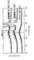
- FIG. 1 is a diagram showing a structural analysis result by X-ray diffraction of an intermediate layer, measured in an example.
- the present inventor has an intermediate layer formed between the base material and the DLC film mainly composed of tungsten carbide, and has a predetermined thickness. As a result, it was found that the adhesion between the base material and the DLC film can be sufficiently enhanced without the intermediate layer having a complicated structure, and the present invention has been completed.
- the intermediate layer according to the present invention is mainly composed of tungsten carbide (WC).
- “mainly composed of tungsten carbide (WC)” means that tungsten carbide (WC) occupies 60% or more of the film thickness in the film thickness direction of the intermediate layer.
- the tungsten carbide (WC) includes tungsten carbide constituting a composition gradient layer (W-WC, WC-C) in addition to tungsten carbide constituting a WC layer (composition single layer) described later.
- W layer in the intermediate layer W which comprises a metal layer
- the WC target may or may not contain Co as a binder.
- Co is a binder component in addition to a rare gas component used during sputtering such as argon as an inevitably contained element. May be included.
- composition form of the intermediate layer examples include the following forms.
- a substantially WC single layer that is, a layer (WC) composed of elements inevitably included with WC (such as the above-described rare gas components that can be used during sputtering, such as argon, and cobalt included as a binder in the WC target). layer
- B A layer (WC / WC-C layer) having a composition gradient structure (WC-C) in which a WC layer is formed immediately above the substrate and carbon increases and tungsten decreases as it approaches the DLC film side.
- the base material side is W (metal)
- Layer having a composition gradient structure (WC-C) in which tungsten is reduced (W-WC / WC / WC-C layer)
- the increase / decrease of the elements in the composition gradient structures (b) to (d) may be stepwise or continuous.
- WC which is the main component of the intermediate layer according to the present invention, contains carbon, which is a constituent element of DLC, and tungsten that constitutes WC has good compatibility with carbon that constitutes DLC. Is expensive.
- the intermediate layer according to the present invention may contain hydrogen. When hydrogen is included, it may contain several at% to about 20 at% hydrogen.
- the hydrogen content may also exhibit a composition gradient structure.
- the WC in the composition gradient structure contains almost no hydrogen, and the amount of hydrogen increases with the amount of C as it goes to the DLC film side (for example, it contains nearly 20 at% hydrogen in the portion in contact with the DLC film).
- the film thickness of the intermediate layer according to the present invention is 40 nm or more and 450 nm or less. As shown in the examples described later, if the film thickness is too thin, problems such as an intermediate layer not being uniformly formed on the surface of the substrate occur, and the effect of improving the adhesion is not fully exhibited. Therefore, the film thickness of the intermediate layer is 40 nm or more. Preferably it is 100 nm or more, More preferably, it is 140 nm or more, More preferably, it is 200 nm or more.
- the film thickness of the intermediate layer is 450 nm or less.
- it is 400 nm or less, More preferably, it is 360 nm or less, More preferably, it is 300 nm or less.
- composition gradient structure in addition to the case where the entire intermediate layer is a composition gradient layer, a WC layer (composition single layer), a composition gradient layer (W-WC formed on the substrate side, and / or Alternatively, a combination of WC-C) formed on the DLC film side can be given.
- the ratio of these to the intermediate layer film thickness is, for example, the film thickness of the composition single layer: the film thickness of the composition gradient layer (base material side and DLC film When formed on both sides, the total film thickness) can be within a range of 1: 1 (preferably 1: 1.5) to 1: 3 (preferably 1: 2.5).
- the film thickness of the lower layer (substrate side) than WC and the upper layer (DLC) of WC is preferably between 1: 1.5 and 1: 4, more preferably between 1: 1.6 and 1: 3.
- the intermediate layer according to the present invention is characterized by low stress as described later and excellent chemical bondability with the DLC film, it is considered that the intermediate layer exhibits better adhesion than conventional intermediate layers and underlayers. .
- a WC-based film (intermediate layer according to the present invention) and a metal film (Cr-based) each having a film thickness of about 300 nm are formed on the same substrate (on a Si (100) wafer), and the amount of deflection of the wafer
- the compressive stress of the WC-based film was -1.5 to -2.0 GPa, whereas the compressive stress of the Cr-based film was -3.0 GPa.
- the compressive stress was higher than that of the WC-based film. From this, it can be seen that the intermediate layer (WC-based film) according to the present invention has lower stress than the metal film.
- the reason why the stress of the intermediate layer according to the present invention is small is considered as follows. That is, when the intermediate layer has an amorphous structure or a microcrystalline structure, the stress is considered to be smaller than that of a metal layer having a crystal structure (specifically, a metal layer that exhibits columnar crystal growth by sputtering). .
- the intermediate layer according to the present case shows an amorphous structure (amorphous structure) or a microcrystalline structure as measured in the 2 ⁇ - ⁇ method by X-ray diffraction as shown in FIG.
- amorphous structure amorphous structure
- microcrystalline structure amorphous structure
- it can be confirmed from the fact that a broad peak is observed in the range of 2 ⁇ 35 ° to 45 °.
- W (0.1 ⁇ m) / WC gradient layer (0.2 ⁇ m) is shown as a comparative example inferior in adhesion.
- This intermediate layer is considered to be inferior in adhesiveness because a sufficient amorphous structure is probably not formed due to the influence of film formation conditions such as hydrogen content, bias voltage, and film formation speed.
- the present invention does not define the DLC film formed on the outermost surface, and a generally known DLC film can be employed.
- a generally known DLC film When applied to sliding parts used as automobile parts or machine parts, hydrogen-containing DLC (aC: H (hydrogenated amorphous carbon) or ta-C: H (hydrogenated) is used as the DLC constituting the DLC film. Tetrahedral amorphous carbon)), hydrogen-free DLC (ta-C (tetrahedral amorphous carbon)), and nitrogen-containing DLC (aC: (H): N) are preferred.
- the film thickness of the DLC film is not particularly limited, and can be, for example, 0.5 ⁇ m to 5.0 ⁇ m. As described above, according to the configuration of the present invention, a relatively thick DLC film can be formed as a single layer.
- the thickness of the DLC film is preferably 1.5 ⁇ m or more, more preferably 1. It can be 8 ⁇ m or more, more preferably 2.0 ⁇ m or more.
- an extremely thin film can be formed as the DLC film.
- the base material is not particularly limited, and iron-based alloys, cemented carbide alloys, titanium-based alloys, aluminum-based alloys, copper-based alloys, ceramics such as glass and alumina, Si, resin materials, and the like can be used.
- iron-based alloy include carbon steel for mechanical structure, structural alloy steel, tool steel, bearing steel, and stainless steel.
- Method for producing DLC film molded body includes PVD methods (arc ion plating methods, sputtering methods such as UBMS methods), CVD methods, and methods combining these methods.
- a tungsten target or a cemented carbide target may be used as the target.
- a WC layer is formed by sputtering a cemented carbide target, and a hydrocarbon gas such as methane, acetylene, benzene or the like is introduced during the film formation using the tungsten target.
- a hydrocarbon gas such as methane, acetylene, benzene or the like
- film forming conditions for forming a sufficient amorphous structure include using a hydrocarbon gas and setting the negative bias voltage to 100 (absolute value) V or more.
- the total gas pressure at the time of forming the intermediate layer (when only argon gas is used as the gas, the pressure of the argon gas is used, and when the mixed gas of argon gas and hydrocarbon gas is used, the pressure of the mixed gas is used.
- the total gas pressure is preferably 1.0 Pa or less, more preferably 0.8 Pa or less.
- DLC film formation examples include a CVD method and a PVD method (UBMS method, AIP method, etc.).
- Examples of the CVD method include a plasma CVD method, and examples thereof include introducing a hydrocarbon gas such as methane, acetylene, benzene, and toluene and forming a DLC film by decomposing the components of the hydrocarbon gas.
- a hydrocarbon gas such as methane, acetylene, benzene, and toluene
- the film formation may be performed using a carbon target and a hydrocarbon gas (for example, methane).
- a hydrocarbon gas for example, methane
- the intermediate layer was formed using an unbalanced magnetron sputtering (UBM202) apparatus manufactured by Kobe Steel. Details are as follows.
- a substrate base material
- a hard metal UTi20t: Mitsubishi Materials
- high-speed steel SKH51
- a Si (100) wafer was prepared for X-ray diffraction analysis (only No. 4 in Table 1 described later) and film thickness measurement.
- the substrate was introduced into the apparatus and evacuated to 1 ⁇ 10 ⁇ 3 Pa or less, and then an intermediate layer was formed.
- a tungsten target (purity 99.9%) or a cemented carbide target (Co is used as a binder manufactured by Allied Material Co., Ltd.) was used for forming the intermediate layer.
- Argon gas and hydrocarbon gas (CH 4 , C 2 H 2 ) are used as process gases, and only argon gas is used when forming a C-free layer, and argon gas and hydrocarbon gas are mixed when forming a C-containing layer.
- Gas was introduced into the chamber.
- the total gas pressure during film formation of the intermediate layer is No. For 1 to 20 and 24 to 30, the pressure is 0.6 Pa. 21 is 0.3 Pa, No. 21 22 and no. 23 was 0.2 Pa.
- the substrate application bias during film formation was kept constant at ⁇ 100V.
- the ratio of tungsten to carbon in the intermediate layer was controlled by changing the ratio of argon gas to hydrocarbon gas in the mixed gas during film formation.
- the input power to the tungsten target or the cemented carbide target was fixed at 2.0 kW, and the film thickness of the intermediate layer was adjusted by the film formation time.
- film formation was also performed using a chromium target, a titanium target, a stainless steel target, a TiAl target, a tantalum target, a molybdenum target, or a niobium target.
- XC (X is WC, Cr, Ti, SUS, TiAl, Ta, Mo, or Nb in Table 1) in the structure of the intermediate layer in Table 1 increases in the amount of C toward the DLC film. 1 shows a composition gradient structure with decreasing amounts.
- the DLC film was formed by two methods.
- One is a method by plasma CVD (PCVD). Specifically, hydrocarbon gas is introduced into the chamber so that the gas pressure becomes 2.0 Pa, and 900 V is applied to the substrate holder from a pulsed DC power source (manufactured by Kyosan Seisakusho) to decompose the components of the hydrocarbon gas. As a result, a DLC film was formed.
- PCVD plasma CVD
- each DLC film shown in Table 1 was formed by using a mixed gas with Ar or changing the hydrocarbon gas ratio.
- Another method is a UBMS method, in which each DLC film shown in Table 1 is formed by applying a power of 2.0 kW to a carbon target and using a mixed gas of CH 4 and Ar as a process gas.
- the intermediate layer is formed by coating the correction liquid on a part of the Si wafer in advance, forming the intermediate layer, and removing the correction liquid after the intermediate layer is formed (that is, the correction liquid and its The intermediate layer formed immediately above was removed), and the level difference between the intermediate layer surface and the substrate surface was measured with a surface roughness meter.
- the thickness of the DLC film was obtained by the following method. That is, the intermediate layer and the DLC film are formed, the total film thickness of (intermediate layer + DLC film) is measured, and the film thickness of the intermediate layer measured in advance by the above method is subtracted from this total film thickness. The film thickness was determined.
- the measurement of Lc was performed for each of a sample whose base material (substrate) was cemented carbide and a sample whose base material (substrate) was high-speed steel. And when a base material was a cemented carbide alloy, since this base material was hard and it was hard to peel, peeling generation
- X-ray diffraction analysis (XRD) of intermediate layer The X-ray diffraction analysis of the intermediate layer was performed using a sample in which only the intermediate layer was formed on high-speed steel.
- Table 1 No. In No. 4, a sample (DLC film molded body) in which a DLC film was further formed on the intermediate layer was also measured.
- X-ray diffraction was measured by 2 ⁇ - ⁇ method using RINT manufactured by RIGAKU.
- FIG. 1 shows a measurement example of a sample (No. 4 in Table 1) that satisfies the requirements of the present invention.
- the data of the WC / WCC (WC / WC-C) layer (film thickness: 303 nm) formed on the Si wafer is free from noise, and a broad peak derived from WC centering around 38 ° is confirmed. can do.
- a peak derived from the high-speed steel is often observed at 40 ° or more. Similar to the sample formed on the Si wafer, a broad peak derived from WC can be confirmed. That is, the presence of a broad peak derived from WC can also be confirmed in the intermediate layer formed on the high-speed steel.
- the thickness of the intermediate layer is in the range of 40 to 450 nm, and the composition of the intermediate layer is WC / WC-C layer (No. 2 to 5, 17, 19, 21, and 22), WC single layer ( In each of No. 8) and W / WC / WC-C layers (No. 11 to 15, 18, 20, and 23), good adhesion was observed, and a broad peak due to XRD was confirmed. Further, from this result, the total gas pressure at the time of forming the intermediate layer was 0.6 Pa. Among these examples, it was found that when the film thickness of the intermediate layer is preferably in the range of about 200 to 300 nm, better adhesion can be obtained.
- No. 17 and 18 are the results of depositing a DLC film by the UBMS method.
- No. 19 and No. No. 20 is an example in which the DLC film is relatively thin.
- No. 19 and No. 3 both of which the intermediate layer is WC / WC-C, and the film thickness of the intermediate layer is substantially the same, it can be confirmed that when the film thickness of the DLC film is relatively thin, high adhesion is exhibited. .
- the intermediate layer of No. 20 In this configuration, a W layer is further formed on the substrate side of the intermediate layer 19 (W / WC / WC-C). It can be seen that, as in FIG. Furthermore, no. 20 and no. 13 (both in which the intermediate layer is W / WC / WC-C, and the film thickness of the intermediate layer is substantially the same), when the film thickness of the DLC film is relatively thin, high adhesion is exhibited. Recognize.
- the upper limit of Lc when the material is high-speed steel is about 70N.
- No. 21 to 23 are examples in which the intermediate layer is formed by lowering the total gas pressure during the formation of the intermediate layer to be lower than the above example. Specifically, the total gas pressure is set to No. 21 is 0.3 Pa, No. 21 22 and no. 23, the film was formed at 0.2 Pa. As a result, these No. In Nos. 21 to 23, although the thickness of the DLC film is as large as 2000 nm or more, Lc in the case where the base material is high speed steel is improved to around 80 N, and shows excellent adhesion. . As described above, this is considered to be due to the fact that, by reducing the total gas pressure, the energy of incident atoms increases and surface diffusion occurs, thereby forming a high-density intermediate layer.
- the intermediate layer No. 23 is No. 23.
- a W layer is further formed on the substrate side of the intermediate layer 21 or 22 (W / WC / WC-C). It turns out that the outstanding adhesiveness is obtained similarly to 21 and 22.
- the intermediate layer is thinner than 40 nm (Nos. 1, 7 and 10)
- the adhesiveness is low in both cases of the cemented carbide and the high speed steel.
- the reason for this is considered as follows. That is, in these examples, since the peak is too weak to be detected even in XRD, the film thickness is too thin and the entire surface of the substrate is not uniformly covered with the intermediate layer, or is incomplete even if covered. It is assumed that it is in a state.
- the intermediate layer is thicker than 450 nm (No. 6, 9 and 16)
- the adhesion is deteriorated when the film is formed on either the cemented carbide or the high speed steel.
- a broad peak derived from WC is confirmed from the result of XRD, and there is no problem in the composition of the film.
- no. In No. 9 since the film thickness of the WC layer is too thick and brittle, it is considered that the scratch test caused a phenomenon in which the WC layer was broken and the DLC film was peeled off.
- a composition gradient layer is formed as an intermediate layer, and the composition gradient layer may have a region with unstable hardness. No. In Nos.
- the composition gradient layer is also relatively thick and the above-mentioned region where the hardness is unstable increases. As a result, the plastic deformation due to scratches cannot be dealt with, and peeling easily occurs. Conceivable.
- No. 24 to 30 are examples in which the constituent elements of the intermediate layer are not specified. In any of these examples, the adhesion was inferior.
- the WC-based intermediate layer of the present invention has interfacial bonding properties with the substrate and the DLC film, In addition, it can be said that the effect of reducing the stress of the intermediate layer is superior to the intermediate layer made of a material other than the WC-based material.
- the DLC film molded body of the present invention is useful as various parts such as sliding members, dies, cutting tools, wear-resistant machine parts, abrasives, magnetic / optical parts, and the like.
Landscapes
- Chemical & Material Sciences (AREA)
- Metallurgy (AREA)
- Chemical Kinetics & Catalysis (AREA)
- Engineering & Computer Science (AREA)
- Materials Engineering (AREA)
- Mechanical Engineering (AREA)
- General Chemical & Material Sciences (AREA)
- Organic Chemistry (AREA)
- Inorganic Chemistry (AREA)
- Cutting Tools, Boring Holders, And Turrets (AREA)
- Physical Vapour Deposition (AREA)
- Laminated Bodies (AREA)
- Chemical Vapour Deposition (AREA)
Abstract
DLC膜が、中間層を介して基材上に形成されたDLC膜成形体であって、前記中間層が、タングステンカーバイドを主成分とし、かつ膜厚が40nm以上450nm以下である。
Description
本発明は、ダイヤモンドライクカーボン(以下、「DLC」という。)膜成形体に関するものであり、DLC膜と基材との密着性に優れたDLC膜成形体に関するものである。
DLCは、ダイヤモンドとグラファイトとの中間的な性質を有する非晶質炭素であり、ダイヤモンドと同様、硬度が高く、耐摩耗性、固体潤滑性、熱伝導性、化学的安定性の特性に優れている。よってDLC膜は、例えば、摺動部材、金型、切削工具類、耐摩耗性機械部品、研磨材、磁気・光学部品等の各種部品の保護膜として利用されつつある。
しかしDLC膜は、基材(特に金属基材)との密着性が悪く、剥離しやすいといった問題がある。剥離が発生する原因として、DLC膜の内部応力が高いことや、金属とDLCとの化学結合が弱いことなどが挙げられる。
そのため、DLC膜と基材との密着性を高めるべく、DLC膜の厚さを非常に薄くすること等がなされている。しかしDLC膜の厚さを非常に薄くすると、DLC膜が有する上記優れた特性が存分に発揮されない場合がある。
DLC膜を一定以上の厚さで形成することを前提に、該DLC膜と基材との密着性を向上させる技術として、該DLC膜と基材の間に中間層を設ける技術が種々提案されている。例えば特許文献1には、前記中間層を、Cr、Alを用いた第1層から第4層までの4層の積層構造とすることによって、前記密着性を向上させることが開示されている。さらに特許文献2には、鋼母材上にDLC膜を形成する際に、5層構造の下地を設けることによって前記密着性を向上させる技術が示されている。
上記技術では、一定以上の厚さのDLC膜を形成する場合、該DLC膜と基材との間に設ける中間層を多層構造とする必要があり、製造工程が煩雑になるといった問題がある。本発明はこの様な事情に着目してなされたものであって、その目的は、一定以上の厚さのDLC膜を形成する場合であっても、上記先行技術よりも簡便な構造の中間層で、DLC膜と基材の密着性を高められるDLC膜成形体を提供することにある。
上記課題を解決し得た本発明のDLC膜成形体は、DLC膜が、中間層を介して基材上に形成されたDLC膜成形体であって、前記中間層が、タングステンカーバイド(WC)を主成分とし、かつ膜厚が40nm以上450nm以下であるところに特徴を有する。
前記中間層は、基材側からDLC膜側に向かって炭素が増加するとともにタングステンが減少する組成傾斜構造を有していることが好ましい。
また前記中間層は、X線回折による構造解析において、2θ=35°~45°にWCに由来するブロードなピークが観測されるものであることが好ましい。
更に、本発明のDLC膜成形体は、前記DLC膜の膜厚が1.5μm以上である場合も、DLC膜と基材の優れた密着性を確保することができる。
従来、DLC膜を一定以上の厚さで形成しようとする場合、中間層を多層構造としなければ十分な密着性が得られなかったが、本発明によれば、簡便な構造の中間層で十分高い密着性を確保することができる。その結果、DLC膜と基材の間の中間層を短時間で成膜でき、生産性の向上を図ることができる。また、該中間層上に一定以上の厚さのDLC膜を形成することもできるので、DLC膜が本来有する耐摩耗性を存分に発揮させることができる。
本発明者は、前記課題を解決するために鋭意研究を重ねた結果、基材とDLC膜との間に形成する中間層を、タングステンカーバイドを主成分とするものであって、所定の厚さとすれば、該中間層を複雑な構造としなくとも、基材とDLC膜の密着性が十分に高められることを見出し、本発明を完成した。
まず、本発明に係る中間層の材質について説明する。
本発明に係る中間層は、タングステンカーバイド(WC)を主成分とするものである。尚、本発明において、「タングステンカーバイド(WC)を主成分とする」とは、中間層の膜厚方向において、膜厚の60%以上をタングステンカーバイド(WC)が占めることを意味する。上記タングステンカーバイド(WC)には、後述するWC層(組成単一層)を構成するタングステンカーバイドの他、組成傾斜層(W-WC、WC-C)を構成するタングステンカーバイドも含まれる。
中間層におけるWC以外の成分として、不可避的に含まれる元素(例えば、アルゴンなどのスパッタリング時に用いうる希ガスの成分や、WCターゲット中にバインダとして含まれるコバルトなど)や、中間層におけるW層(金属層)を構成するWなどが挙げられる。尚、WCターゲットにはバインダとしてCoを含んでも含まなくてもよく、バインダを含む場合は、不可避的に含まれる元素としてアルゴンなどのスパッタリング時に用いる希ガスの成分に加え、バインダ成分であるCoなどを含んでもよい。
上記中間層の組成形態(膜厚方向の組成形態)として、下記の形態が挙げられる。
(a)実質WC単層、即ち、WCと不可避的に含まれる元素(上述したアルゴンなどのスパッタリング時に用いうる希ガスの成分や、WCターゲット中にバインダとして含まれるコバルトなど)からなる層(WC層)、
また、組成傾斜構造を有する形態として、
(b)基材直上にWC層が形成され、DLC膜側に近づくにつれて炭素が増加するとともにタングステンが減少する組成傾斜構造(WC-C)を有する層(WC/WC-C層)
(c)基材直上にW(金属)層が形成され、次いでWC層が形成され、DLC膜側に近づくにつれて炭素が増加するとともにタングステンが減少する組成傾斜構造(WC-C)を有する層(W/WC/WC-C層)
(d)基材側がW(金属)であり、DLC膜側に近づくにつれて炭素が増加する組成傾斜構造(W-WC)、次いでWC層が形成され、DLC膜側に近づくにつれて炭素が増加するとともにタングステンが減少する組成傾斜構造(WC-C)を有する層(W-WC/WC/WC-C層)
上記(b)~(d)の組成傾斜構造における元素の増減は、段階的または連続的であればよい。
本発明に係る中間層の主成分であるWCは、DLCの構成元素であるカーボンを含んでおり、WCを構成するタングステンもDLCを構成するカーボンと相性が良いため、DLC膜との化学結合性が高い。
また、上記(b)~(d)の通り、DLC膜との界面付近の炭素量を増加させた組成傾斜構造(WC-C)を採用することによって、中間層とDLC膜との界面結合性が更に増加する。更には上記(d)の通り、基材(特には金属基材)との界面付近のW(金属成分)量を増加させた組成傾斜構造(W-WC)を採用することによって、基材と中間層の界面結合性も増加し、DLC膜成形体全体の密着性が更に向上する。
本発明に係る中間層は、水素を含む場合がある。水素を含む場合、数at%~約20at%の水素を含みうる。
上記(b)~(d)の通り、DLC膜との界面付近の炭素量を増加させた組成傾斜構造(WC-C)を有する場合、水素量も組成傾斜構造を示す場合がある。即ち、組成傾斜構造におけるWCには水素がほとんど含まれず、DLC膜側に向かうにつれてC量と共に水素量が増加する(例えば、DLC膜と接する部分で20at%近い水素を含む)場合がある。
〔中間層の膜厚〕
本発明に係る中間層の膜厚は、40nm以上450nm以下である。後述する実施例に示す通り、該膜厚が薄すぎると、基材表面に中間層が均一に形成されない等の不具合が生じ、密着性向上効果が存分に発揮されない。よって中間層の膜厚は40nm以上とする。好ましくは100nm以上、より好ましくは140nm以上、更に好ましくは200nm以上である。
本発明に係る中間層の膜厚は、40nm以上450nm以下である。後述する実施例に示す通り、該膜厚が薄すぎると、基材表面に中間層が均一に形成されない等の不具合が生じ、密着性向上効果が存分に発揮されない。よって中間層の膜厚は40nm以上とする。好ましくは100nm以上、より好ましくは140nm以上、更に好ましくは200nm以上である。
一方、中間層の膜厚が厚すぎると、中間層はDLC膜に比べて硬度が低いため、中間層を起点としてクラックが発生し、該クラックが進展してDLC膜の剥離に至る、といった不具合が生じる。また組成傾斜構造を有する場合、中間層の膜厚が厚すぎると硬度の不安定な領域が生じ、密着性がかえって低下する。よって、中間層の膜厚は450nm以下とする。好ましくは400nm以下、より好ましくは360nm以下、更に好ましくは300nm以下である。
尚、上記組成傾斜構造を形成する場合、中間層全体が組成傾斜層である場合の他、WC層(組成単一層)と、組成傾斜層(基材側に形成されるW-WC、および/または、DLC膜側に形成されるWC-C)の組み合わせが挙げられる。
中間層が、この組成単一層と組成傾斜層の組み合わせの場合、中間層膜厚に占めるこれらの割合を、例えば、組成単一層の膜厚:組成傾斜層の膜厚(基材側とDLC膜側の両方に形成される場合は合計膜厚)=1:1(好ましくは1:1.5)~1:3(好ましくは1:2.5)の範囲内とすることができる。また、(c)のW/WC/WC-C及び(d)のW/W-WC/WC/WC-Cでは、WCよりも下層(基板側)の膜厚と、WCよりも上層(DLC側)の膜厚との比が1:1.5~1:4の間にあることが好ましく、更に好ましくは1:1.6~1:3の間である。
本発明に係る中間層は、特徴として、後述する通り応力が小さく、かつDLC膜との化学結合性に優れているため、従来の中間層や下地層よりも優れた密着性を発揮すると考えられる。
実際に、膜厚が300nm程度の、WC系皮膜(本発明に係る中間層)と金属膜(Cr系)をそれぞれ、同一基板(Si(100)ウエハ上)に形成して、ウエハのたわみ量を測定し、Stoneyの式から応力を算出・対比したところ、WC系皮膜の圧縮応力は-1.5~-2.0GPaであったのに対し、Cr系皮膜の圧縮応力は-3.0GPa程度であり、WC系皮膜よりも高い圧縮応力を示した。このことから、本発明に係る中間層(WC系皮膜)は、金属膜よりも応力が低いことがわかる。
この様に本発明に係る中間層の応力が小さい理由として、次のことが考えられる。即ち、中間層が非晶質構造または微結晶構造を示す場合に、結晶構造を有する金属層(具体的には、スパッタ法で柱状の結晶成長を示す金属層)よりも応力が小さくなると考えられる。
上記の通り、本件に係る中間層が非晶質構造(アモルファス構造)または微結晶構造を示すことは、後述する実施例で測定した図1に示す通り、X線回折による2θ-θ法の測定で、2θ=35°~45°の範囲内にブロードなピークが観察されることから確認できる。これに対し、WCが結晶性の構造である場合には、2θ=36°付近にシャープな(100)回折線が確認される。
尚、上記特許文献1の表1には、W(0.1μm)/WC傾斜層(0.2μm)が密着性に劣る比較例として示されている。この中間層は、水素含有量やバイアス電圧、成膜速度等の成膜条件の影響により、おそらく十分な非晶質構造が形成されていないため、密着性に劣っていると思われる。
〔DLC膜〕
本発明は、最表面に形成するDLC膜まで規定するものでなく、一般的に知られているDLC膜を採用することができる。自動車部品や機械部品等として用いられる摺動部品に適用する場合、DLC膜を構成するDLCとして、水素含有DLC(a-C:H(水素化アモルファスカーボン)や、ta-C:H(水素化テトラヘドラルアモルファスカーボン))、水素フリーDLC(ta-C(テトラヘドラルアモルファスカーボン))、窒素含有DLC(a-C:(H):N)が好ましい。
本発明は、最表面に形成するDLC膜まで規定するものでなく、一般的に知られているDLC膜を採用することができる。自動車部品や機械部品等として用いられる摺動部品に適用する場合、DLC膜を構成するDLCとして、水素含有DLC(a-C:H(水素化アモルファスカーボン)や、ta-C:H(水素化テトラヘドラルアモルファスカーボン))、水素フリーDLC(ta-C(テトラヘドラルアモルファスカーボン))、窒素含有DLC(a-C:(H):N)が好ましい。
DLC膜の膜厚も、特に限定されず、例えば0.5μm~5.0μmとすることができる。上述した通り、本発明の構成によれば、比較的膜厚の厚いDLC膜を単層で形成することもでき、例えば該DLC膜の膜厚を好ましくは1.5μm以上、より好ましくは1.8μm以上、更に好ましくは2.0μm以上とすることができる。この様にDLC膜の膜厚が厚い場合であっても、基材との優れた密着性を維持でき、かつDLC膜の有する耐摩耗性等の効果が存分に発揮される。勿論、DLC膜として極めて薄い膜を形成することもできる。
〔基材〕
基材は、特に限定されず、鉄系合金、超硬合金、チタン系合金、アルミ系合金、銅系合金、ガラス、アルミナなどのセラミックス、Si、樹脂材料等を用いることができる。前記鉄系合金としては、例えば機械構造用炭素鋼、構造用合金鋼、工具鋼、軸受鋼、ステンレス鋼などが挙げられる。
基材は、特に限定されず、鉄系合金、超硬合金、チタン系合金、アルミ系合金、銅系合金、ガラス、アルミナなどのセラミックス、Si、樹脂材料等を用いることができる。前記鉄系合金としては、例えば機械構造用炭素鋼、構造用合金鋼、工具鋼、軸受鋼、ステンレス鋼などが挙げられる。
〔DLC膜成形体の製造方法〕
(中間層の成膜)
中間層の形成方法として、PVD法(アークイオンプレーティング法、UBMS法等のスパッタリング法等)、CVD法、これらの方法を複合した方法等が挙げられる。
(中間層の成膜)
中間層の形成方法として、PVD法(アークイオンプレーティング法、UBMS法等のスパッタリング法等)、CVD法、これらの方法を複合した方法等が挙げられる。
例えば、スパッタリング法で形成する場合、ターゲットとして例えばタングステンターゲットや超硬合金ターゲットを用いればよい。具体的成膜方法として、例えば、超硬合金ターゲットをスパッタリングしてWC層を形成する他、上記タングステンターゲットを用い、成膜中にメタン、アセチレン、ベンゼン等の炭化水素ガスを導入して、反応性スパッタリングを行い、WとCの比率が異なる層を形成することが挙げられる。また、タングステンターゲットと、C(カーボン)ターゲットを同時にスパッタすること等も挙げられる。尚、十分な非晶質構造を形成するための成膜条件として、炭化水素ガスを使用することや、負バイアスの電圧を100(絶対値)V以上とすること等が挙げられる。
また、中間層成膜時の全ガス圧(ガスとして、アルゴンガスのみ使用時は、アルゴンガスの圧力をいい、アルゴンガスと炭化水素ガスの混合ガスの使用時は、該混合ガスの圧力をいう。以下同じ)は、例えば0.05~5.0Paの範囲とすることができる。より高い密着性を得るべく中間層の更なる緻密化を図るには、この全ガス圧を、1.0Pa以下とすることが好ましく、より好ましくは0.8Pa以下である。この様に全ガス圧を下げることにより、入射原子のエネルギーが高くなって表面拡散が起こり、密度の高い中間層が形成されると考えられる。
(DLC膜の成膜)
DLC膜の形成方法として、例えばCVD法、PVD法(UBMS法や、AIP法等)が挙げられる。
DLC膜の形成方法として、例えばCVD法、PVD法(UBMS法や、AIP法等)が挙げられる。
CVD法として、例えばプラズマCVD法が挙げられ、メタン、アセチレン、ベンゼン、トルエン等の炭化水素ガスを導入し、この炭化水素ガスの成分を分解することによってDLC膜を成膜することが挙げられる。
また、例えばUBMS法で形成する場合には、例えばカーボンターゲットと炭化水素ガス(例えば、メタン)を用いて成膜することが挙げられる。
以下、実施例を挙げて本発明をより具体的に説明するが、本発明はもとより下記実施例によって制限を受けるものではなく、前・後記の趣旨に適合し得る範囲で適当に変更を加えて実施することも勿論可能であり、それらはいずれも本発明の技術的範囲に包含される。
中間層の成膜は、神戸製鋼所製アンバランスドマグネトロンスパッタ(UBM202)装置を用いて行った。詳細は次の通りである。
基板(基材)として、スクラッチ試験用および中間層のX線回折分析用に、表面を鏡面研磨した超硬合金(UTi20t:三菱マテリアル)と高速度鋼(SKH51)を用意し、また中間層のX線回折分析用(後述する表1のNo.4のみ)および膜厚測定用に、Si(100)ウエハを用意した。
上記基材を装置内に導入し、1×10⁻³Pa以下に排気した後に、中間層の成膜を実施した。中間層の成膜には、タングステンターゲット(純度99.9%)、または超硬合金ターゲット(株式会社アライドマテリアル製 バインダーとしてCoを使用)を用いた。
プロセスガスとして、アルゴンガスと炭化水素ガス(CH4、C2H2)を用い、C非含有層の形成時はアルゴンガスのみ、またC含有層の形成時はアルゴンガスと炭化水素ガスの混合ガスをチャンバー内に導入した。中間層成膜時の全ガス圧は、No.1~20、および24~30では0.6Paとし、No.21では0.3Pa、No.22とNo.23では0.2Paとした。また成膜時の基板印加バイアスは-100V一定とした。成膜時の混合ガスにおけるアルゴンガスと炭化水素ガスの比を変化させることによって、中間層中のタングステンと炭素との比率を制御した。タングステンターゲットまたは超硬合金ターゲットへの投入電力は2.0kWで一定とし、中間層の膜厚は成膜時間により調整した。
また比較例として、上記タングステンターゲットの代わりに、下記表1のNo.24~30に示す通り、クロムターゲット、チタンターゲット、ステンレス鋼ターゲット、TiAlターゲット、タンタルターゲット、モリブデンターゲット、またはニオブターゲットを用いた成膜も行った。
表1の中間層の構成における「X-C」(Xは、表1におけるWC、Cr、Ti、SUS、TiAl、Ta、MoまたはNb)は、DLC膜に向かうにつれてC量が増加し、X量が減少する組成傾斜構造を示す。
中間層の成膜では、プロセスにより若干変化するが、組成単一層の膜厚:組成傾斜層の膜厚=1:2とした。
次いで、DLC膜を形成した。DLC膜の成膜は2種類の方法で行った。一つは、プラズマCVD(PCVD)による方法である。詳細には、チャンバー内に炭化水素ガスを、ガス圧が2.0Paとなるように導入し、基板ホルダーにパルスDC電源(京三製作所製)から900Vを印加し、炭化水素ガスの成分を分解することによってDLC膜を成膜した。本方法では、Arとの混合ガスを用いることや炭化水素ガス比率を変化させることで、表1に示す各DLC膜を成膜した。もう一つの方法は、UBMS手法であり、カーボンターゲットに2.0kWの電力を印加し、プロセスガスとしてCH4とArの混合ガスを用いることで表1に示す各DLC膜を成膜した。
尚、中間層の膜厚は、あらかじめSiウエハ上の一部に修正液を塗布してから中間層を成膜し、この中間層の成膜後に該修正液を除去(即ち、修正液とその直上に形成された中間層を除去)して、中間層表面と基板表面の段差を表面粗さ計で測定して求めた。
また、DLC膜の膜厚は次の方法で求めた。即ち、中間層およびDLC膜の成膜を行って、(中間層+DLC膜)の合計膜厚を測定し、この合計膜厚から、上記方法であらかじめ測定した中間層の膜厚を差し引いて、DLC膜の膜厚を求めた。
上記各種条件で得られた試料(基板上に中間層のみ形成したものやDLC膜成形体)を用いて、下記の測定を行った。
〔DLC膜と基板の密着性評価〕
DLC膜と基板の密着性を評価するため、スクラッチ試験を行った。スクラッチ試験では、試料を移動速度10mm/分で移動させつつ、先端の曲率半径が200μmのダイヤモンド圧子で試料表面を押圧した。押圧負荷を荷重増加速度100N/分で、0Nから100Nまで増大させながら(最大荷重100N)、皮膜の剥離が開始した時点の荷重、即ち、剥離発生臨界荷重Lc(Critical Load)を調べた。尚、剥離の開始は、上記装置に付属の光学顕微鏡で観察して確認した。
DLC膜と基板の密着性を評価するため、スクラッチ試験を行った。スクラッチ試験では、試料を移動速度10mm/分で移動させつつ、先端の曲率半径が200μmのダイヤモンド圧子で試料表面を押圧した。押圧負荷を荷重増加速度100N/分で、0Nから100Nまで増大させながら(最大荷重100N)、皮膜の剥離が開始した時点の荷重、即ち、剥離発生臨界荷重Lc(Critical Load)を調べた。尚、剥離の開始は、上記装置に付属の光学顕微鏡で観察して確認した。
上記Lcの測定は、基材(基板)が超硬合金である試料、基材(基板)が高速度鋼である試料のそれぞれについて行った。そして、基材が超硬合金の場合は、該基材が硬く剥離し難いことから、剥離発生臨界荷重Lcが80N以上を合格とした。一方、基材が高速度鋼の場合は、基材が組成変形しやすく剥離しやすいため、剥離発生臨界荷重Lcが60N以上の場合を合格とした。そして本実施例では、基材が超硬合金の場合と高速度鋼の場合の両方が合格の場合を、密着性に優れると評価した。
〔中間層のX線回折分析(XRD)〕
中間層のX線回折分析は、高速度鋼上に中間層のみが形成されている試料を用いて行った。尚、表1のNo.4では、中間層上に更にDLC膜の形成された試料(DLC膜成形体)についても測定を行った。
中間層のX線回折分析は、高速度鋼上に中間層のみが形成されている試料を用いて行った。尚、表1のNo.4では、中間層上に更にDLC膜の形成された試料(DLC膜成形体)についても測定を行った。
X線回折は、RIGAKU社製RINTを用い、2θ-θ法で測定を行った。線源としてCu-Kα線を用い、パラメータとして管電圧:20kV、管電流:20mA、角度範囲2θ=20°~80°で0.02°刻みでの測定を実施した。
図1に、本発明の要件を満たす試料(表1のNo.4)の測定例を示す。この図1から、Siウエハ上に形成したWC/WCC(WC/WC-C)層(膜厚:303nm)のデータはノイズがなく、38°付近を中心としたWC由来のブロードなピークを確認することができる。さらに、高速度鋼上に成膜されたWC/WC-C層(膜厚:303nm)のデータでは、高速度鋼由来のピークが40°以上で多くみられるが、38°付近には、上記Siウエハ上に形成した試料と同様の、WC由来のブロードなピークを確認できる。即ち、高速度鋼上に形成された中間層においても、WC由来のブロードなピークの存在を確認できる。
更に、中間層の上にDLC膜を成膜した試料では、DLCは完全に非晶質であることから、X線回折結果には反映されておらず、下地のみのデータ(即ち、高速度鋼/WC/WC-C)と同様の結果が得られている。つまりこの図1では、中間層上に更にDLC膜が形成されている場合であっても、DLC膜が形成されていない場合と同様に、中間層のX線回折分析(XRD)を行えることを示している。
表1のNo.4以外の例についても、上記図1に示す様なX線回折結果から、2θ=35°~45°のWC由来のブロードピークの有無を確認した。そして、このブロードピークがみられるものは、XRDブロードピークが「あり」とし、該ピークがみられないものは「なし」と評価した。
これらの結果を表1に示す。
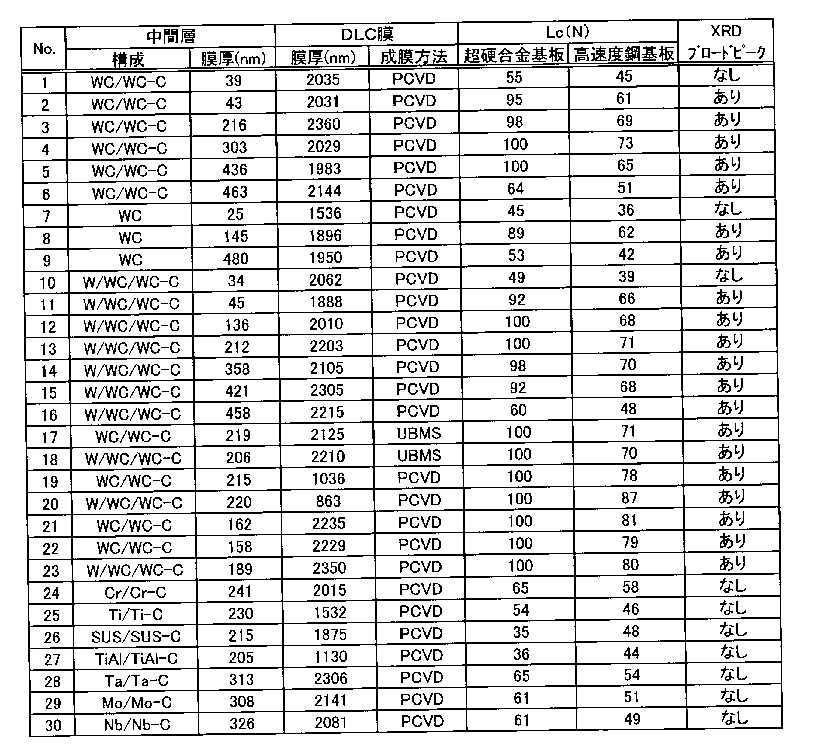
表1より次の様に考察することができる。
まず、中間層の膜厚が40~450nmの範囲内にあり、かつ中間層の組成が、WC/WC-C層(No.2~5、17、19、21および22)、WC単層(No.8)、W/WC/WC-C層(No.11~15、18、20および23)のいずれの場合も、良好な密着性を示すと共に、XRDによるブロードなピークも確認できた。また本結果から、中間層成膜時の全ガス圧が0.6Paである上記No.の例のうち、中間層の膜厚が、好ましくは約200~300nmの範囲内の場合には、より優れた密着性が得られることがわかった。
尚、No.17および18は、特にDLC膜をUBMS手法で成膜した結果である。中間層が同じであってPCVD法でDLC膜を成膜したNo.3やNo.13と比較すると、ほとんど同じ結果を示している。このことから、本発明に係る中間層は、DLC膜の製法によらず、良好な密着性を発揮することが分かる。
No.19およびNo.20は、DLC膜の膜厚が比較的薄い例である。No.19とNo.3(いずれも、中間層がWC/WC-Cであり、中間層の膜厚がほぼ同じ)との対比から、DLC膜の膜厚が比較的薄い場合、高い密着性を示すことを確認できる。またNo.20の中間層は、No.19の中間層の基板側に更にW層を形成した構成(W/WC/WC-C)であるが、この中間層を形成した場合も、No.19と同様に高い密着性を示すことがわかる。更に、No.20とNo.13(いずれも、中間層がW/WC/WC-Cであり、中間層の膜厚がほぼ同じ)との対比から、DLC膜の膜厚が比較的薄い場合、高い密着性を示すことがわかる。
中間層成膜時の全ガス圧を0.6Paとした場合であって、DLC膜の膜厚が約2000nm以上と厚い場合(例えばNo.2~4、12~15、17、18)、基材が高速度鋼の場合のLcは、上限が70N程度である。
これに対し、No.21~23(DLC膜の膜厚はいずれも2000nm以上)は、中間層形成時の全ガス圧を、上記例よりも低くして中間層を形成した例である。具体的には、全ガス圧を、No.21では0.3Pa、No.22とNo.23では0.2Paとして成膜した。その結果、これらNo.21~23は、DLC膜の膜厚が2000nm以上と厚いにもかかわらず、基材が高速度鋼の場合のLcは、いずれも80N前後まで向上しており、優れた密着性を示している。これは前述の通り、全ガス圧を下げることで、入射原子のエネルギーが高くなり、表面拡散が起こることによって、密度の高い中間層が形成されたことによると考えられる。
また上記No.23の中間層は、No.21や22の中間層の基板側に更にW層を形成した構成(W/WC/WC-C)であるが、この中間層を形成した場合も、No.21や22と同様に優れた密着性が得られることがわかる。
これに対し、中間層が40nmよりも薄い場合(No.1、7および10)には、基板が超硬合金と高速度鋼のいずれの場合も密着性が低い。この理由としては次の様なことが考えられる。即ち、これらの例では、XRDでもピークが弱すぎて検出されていないことから、膜厚が薄すぎて基板の全面が中間層で均一に覆われていないか、覆われていても不完全な状態であることが想定される。
また中間層が450nmよりも厚い場合(No.6、9および16)、超硬合金上と高速度鋼上のいずれに成膜した場合も密着性が悪くなっている。これらの例では、XRDの結果からWCに由来のブロードなピークが確認されており膜の組成は問題ない。しかしNo.9では、WC層の膜厚が厚すぎて脆いため、スクラッチ試験で、WC層から破壊が発生してDLC膜も剥離するといった現象が生じたものと考えられる。またNo.6および16では、中間層として組成傾斜層を形成しているが、該組成傾斜層は硬度の不安定な領域を有する場合がある。No.6および16では、膜厚が厚いため、相対的に組成傾斜層も厚くなって上記硬度が不安定な領域が増大し、結果としてスクラッチによる塑性変形に対応できず、剥離が発生しやすくなったと考えられる。
また、No.24~30は、中間層の構成元素が規定外の例である。これらいずれの例も、密着性が劣る結果となった。
このNo.24~30とNo.2~5、8、11~15および19~23(いずれもDLC膜をPCVD法で成膜)との比較から、本発明のWC系中間層は、基材およびDLC膜との界面結合性、ならびに中間層の応力の低減の効果が、WC系以外の材質の中間層よりも優れているといえる。
本発明を詳細にまた特定の実施態様を参照して説明したが、本発明の精神と範囲を逸脱することなく様々な変更や修正を加えることができることは当業者にとって明らかである。
本出願は、2012年6月29日出願の日本特許出願(特願2012-146681)及び2012年11月20日出願の日本特許出願(特願2012-254164)に基づくものであり、その内容はここに参照として取り込まれる。
本出願は、2012年6月29日出願の日本特許出願(特願2012-146681)及び2012年11月20日出願の日本特許出願(特願2012-254164)に基づくものであり、その内容はここに参照として取り込まれる。
本発明のDLC膜成形体は、摺動部材、金型、切削工具類、耐摩耗性機械部品、研磨材、磁気・光学部品等の各種部品等として有用である。
Claims (5)
- ダイヤモンドライクカーボン(DLC)膜が、中間層を介して基材上に形成されたDLC膜成形体であって、
前記中間層は、タングステンカーバイド(WC)を主成分とし、かつ膜厚が40nm以上450nm以下であることを特徴とするDLC膜成形体。 - 前記中間層は、基材側からDLC膜側に向かって炭素が増加するとともにタングステンが減少する組成傾斜構造を有するものである請求項1に記載のDLC膜成形体。
- 前記中間層は、X線回折による構造解析において、2θ=35°~45°にWCに由来するブロードなピークが観測されるものである請求項1または2に記載のDLC膜成形体。
- 前記DLC膜は、膜厚が1.5μm以上である請求項1または2に記載のDLC膜成形体。
- 前記DLC膜は、膜厚が1.5μm以上である請求項3に記載のDLC膜成形体。
Applications Claiming Priority (4)
| Application Number | Priority Date | Filing Date | Title |
|---|---|---|---|
| JP2012-146681 | 2012-06-29 | ||
| JP2012146681 | 2012-06-29 | ||
| JP2012254164 | 2012-11-20 | ||
| JP2012-254164 | 2012-11-20 |
Publications (1)
| Publication Number | Publication Date |
|---|---|
| WO2014003172A1 true WO2014003172A1 (ja) | 2014-01-03 |
Family
ID=49783306
Family Applications (1)
| Application Number | Title | Priority Date | Filing Date |
|---|---|---|---|
| PCT/JP2013/067833 WO2014003172A1 (ja) | 2012-06-29 | 2013-06-28 | Dlc膜成形体 |
Country Status (2)
| Country | Link |
|---|---|
| JP (1) | JP6172799B2 (ja) |
| WO (1) | WO2014003172A1 (ja) |
Cited By (4)
| Publication number | Priority date | Publication date | Assignee | Title |
|---|---|---|---|---|
| WO2019181742A1 (ja) * | 2018-03-19 | 2019-09-26 | 住友電気工業株式会社 | 表面被覆切削工具 |
| WO2019181740A1 (ja) * | 2018-03-19 | 2019-09-26 | 住友電気工業株式会社 | 表面被覆切削工具 |
| WO2019181741A1 (ja) * | 2018-03-19 | 2019-09-26 | 住友電気工業株式会社 | 表面被覆切削工具 |
| EP3845769A4 (en) * | 2018-08-29 | 2022-06-08 | NTN Corporation | DOUBLE ROW SELF-ALIGNING ROLLER BEARING AND EQUIPPED MAIN SHAFT SUPPORT FOR WIND GENERATION |
Families Citing this family (6)
| Publication number | Priority date | Publication date | Assignee | Title |
|---|---|---|---|---|
| JP2016056435A (ja) | 2014-09-12 | 2016-04-21 | 株式会社神戸製鋼所 | 硬質摺動部材の製造方法、および硬質摺動部材 |
| JP5903181B1 (ja) * | 2015-06-09 | 2016-04-13 | 株式会社吉城光科学 | 液晶表示画面保護シート |
| CN107034467B (zh) * | 2017-03-13 | 2019-12-03 | 深圳先进技术研究院 | 一种具有金刚石涂层的硬质合金件及其制备方法 |
| JP7218042B2 (ja) * | 2017-08-04 | 2023-02-06 | エリコン サーフェス ソリューションズ アーゲー、 プフェフィコン | 性能を強化したタップドリル |
| EP3650582A1 (en) | 2018-11-08 | 2020-05-13 | Nanofilm Technologies International Pte Ltd | Temperature resistant amorphous carbon coatings |
| CN110735126B (zh) * | 2019-10-24 | 2021-09-14 | 江苏亿阀股份有限公司 | 一种在钢基体上制备碳化钨过渡层-硅掺杂金刚石复合涂层的方法 |
Citations (5)
| Publication number | Priority date | Publication date | Assignee | Title |
|---|---|---|---|---|
| JPH03295552A (ja) * | 1990-04-13 | 1991-12-26 | Shin Etsu Chem Co Ltd | 歯科用切削具の製造法 |
| JP2000119843A (ja) * | 1998-10-12 | 2000-04-25 | Kobe Steel Ltd | ダイヤモンドライクカーボン硬質多層膜成形体 |
| JP2001192864A (ja) * | 1998-12-25 | 2001-07-17 | Sumitomo Electric Ind Ltd | 硬質被膜及び被覆部材 |
| JP2004018907A (ja) * | 2002-06-13 | 2004-01-22 | Kobe Steel Ltd | 溝付きプラグ |
| JP2007070667A (ja) * | 2005-09-05 | 2007-03-22 | Kobe Steel Ltd | ダイヤモンドライクカーボン硬質多層膜成形体およびその製造方法 |
Family Cites Families (4)
| Publication number | Priority date | Publication date | Assignee | Title |
|---|---|---|---|---|
| JPH0994911A (ja) * | 1995-09-29 | 1997-04-08 | Ntn Corp | 硬質カーボン膜成形体 |
| JP4139102B2 (ja) * | 2001-12-06 | 2008-08-27 | 株式会社デンソー | ダイヤモンドライクカーボン硬質多層膜成形体およびその製造方法 |
| JP4898162B2 (ja) * | 2005-07-25 | 2012-03-14 | 東芝キヤリア株式会社 | 密閉型圧縮機および冷凍サイクル装置 |
| JP2007118594A (ja) * | 2005-09-30 | 2007-05-17 | Think Laboratory Co Ltd | グラビア製版ロール及びその製造方法 |
-
2013
- 2013-06-28 JP JP2013137138A patent/JP6172799B2/ja not_active Expired - Fee Related
- 2013-06-28 WO PCT/JP2013/067833 patent/WO2014003172A1/ja active Application Filing
Patent Citations (5)
| Publication number | Priority date | Publication date | Assignee | Title |
|---|---|---|---|---|
| JPH03295552A (ja) * | 1990-04-13 | 1991-12-26 | Shin Etsu Chem Co Ltd | 歯科用切削具の製造法 |
| JP2000119843A (ja) * | 1998-10-12 | 2000-04-25 | Kobe Steel Ltd | ダイヤモンドライクカーボン硬質多層膜成形体 |
| JP2001192864A (ja) * | 1998-12-25 | 2001-07-17 | Sumitomo Electric Ind Ltd | 硬質被膜及び被覆部材 |
| JP2004018907A (ja) * | 2002-06-13 | 2004-01-22 | Kobe Steel Ltd | 溝付きプラグ |
| JP2007070667A (ja) * | 2005-09-05 | 2007-03-22 | Kobe Steel Ltd | ダイヤモンドライクカーボン硬質多層膜成形体およびその製造方法 |
Cited By (8)
| Publication number | Priority date | Publication date | Assignee | Title |
|---|---|---|---|---|
| WO2019181742A1 (ja) * | 2018-03-19 | 2019-09-26 | 住友電気工業株式会社 | 表面被覆切削工具 |
| WO2019181740A1 (ja) * | 2018-03-19 | 2019-09-26 | 住友電気工業株式会社 | 表面被覆切削工具 |
| WO2019181741A1 (ja) * | 2018-03-19 | 2019-09-26 | 住友電気工業株式会社 | 表面被覆切削工具 |
| CN110691664A (zh) * | 2018-03-19 | 2020-01-14 | 住友电气工业株式会社 | 表面被覆切削工具 |
| JPWO2019181742A1 (ja) * | 2018-03-19 | 2020-07-27 | 住友電気工業株式会社 | 表面被覆切削工具 |
| JPWO2019181741A1 (ja) * | 2018-03-19 | 2020-07-27 | 住友電気工業株式会社 | 表面被覆切削工具 |
| JPWO2019181740A1 (ja) * | 2018-03-19 | 2020-07-27 | 住友電気工業株式会社 | 表面被覆切削工具 |
| EP3845769A4 (en) * | 2018-08-29 | 2022-06-08 | NTN Corporation | DOUBLE ROW SELF-ALIGNING ROLLER BEARING AND EQUIPPED MAIN SHAFT SUPPORT FOR WIND GENERATION |
Also Published As
| Publication number | Publication date |
|---|---|
| JP2014122415A (ja) | 2014-07-03 |
| JP6172799B2 (ja) | 2017-08-02 |
Similar Documents
| Publication | Publication Date | Title |
|---|---|---|
| JP6172799B2 (ja) | Dlc膜成形体 | |
| Khadem et al. | Tribology of multilayer coatings for wear reduction: A review | |
| JP4918656B2 (ja) | 非晶質硬質炭素皮膜 | |
| JP4704950B2 (ja) | 非晶質炭素系硬質多層膜及びこの膜を表面に備えた硬質表面部材 | |
| KR100845372B1 (ko) | 유사 다이아몬드 카본 경질 다층 필름 형성 본체 및 이를제조하는 방법 | |
| Ziebert et al. | Hard multilayer coatings containing TiN and/or ZrN: A review and recent progress in their nanoscale characterization | |
| JP5641124B2 (ja) | 硬質皮膜被覆部材の製造方法 | |
| JP4373897B2 (ja) | 硬質皮膜被覆部材及びその被覆方法 | |
| US9371576B2 (en) | Coated tool and methods of making and using the coated tool | |
| JP5303816B2 (ja) | 硬質皮膜被覆工具 | |
| CN102649331B (zh) | 一种具有超硬膜涂层的刀具及其制备方法 | |
| JP2009167512A (ja) | 摺動部品用ダイヤモンドライクカーボン皮膜およびその製造方法 | |
| Cai et al. | Improved adhesion and cutting performance of AlTiSiN coatings by tuning substrate bias voltage combined with Ar ion cleaning pre-treatment | |
| Cao et al. | Microstructure, mechanical and tribological properties of multilayer TiAl/TiAlN coatings on Al alloys by FCVA technology | |
| US8962100B2 (en) | Method for making diamond composite materials | |
| JP5660457B2 (ja) | 硬質皮膜被覆金型 | |
| JP5226826B2 (ja) | ダイヤモンドライクカーボン硬質多層膜成形体の製造方法 | |
| JP2007277663A (ja) | 摺動材 | |
| US20090226715A1 (en) | Coated article and method of making the same | |
| Li et al. | Optimization of interlayer/CrWN bilayer films fabricated and monitored under Shewhart control | |
| JP5614405B2 (ja) | 硬質皮膜被覆工具及びその製造方法 | |
| JP3884378B2 (ja) | 密着性に優れた硬質皮膜 | |
| JP2006169614A (ja) | 金属複合ダイヤモンドライクカーボン(dlc)皮膜、その形成方法、及び摺動部材 | |
| JP2914142B2 (ja) | 傾斜組成膜およびその製造方法ならびに工具 | |
| JP2011189499A (ja) | 硬質皮膜被覆工具 |
Legal Events
| Date | Code | Title | Description |
|---|---|---|---|
| 121 | Ep: the epo has been informed by wipo that ep was designated in this application |
Ref document number: 13808798 Country of ref document: EP Kind code of ref document: A1 |
|
| NENP | Non-entry into the national phase |
Ref country code: DE |
|
| 122 | Ep: pct application non-entry in european phase |
Ref document number: 13808798 Country of ref document: EP Kind code of ref document: A1 |