WO2014002891A1 - 音叉型水晶振動子及びその製造方法 - Google Patents
音叉型水晶振動子及びその製造方法 Download PDFInfo
- Publication number
- WO2014002891A1 WO2014002891A1 PCT/JP2013/067080 JP2013067080W WO2014002891A1 WO 2014002891 A1 WO2014002891 A1 WO 2014002891A1 JP 2013067080 W JP2013067080 W JP 2013067080W WO 2014002891 A1 WO2014002891 A1 WO 2014002891A1
- Authority
- WO
- WIPO (PCT)
- Prior art keywords
- fork type
- tuning fork
- vibrating
- type crystal
- crystal resonator
- Prior art date
- Legal status (The legal status is an assumption and is not a legal conclusion. Google has not performed a legal analysis and makes no representation as to the accuracy of the status listed.)
- Ceased
Links
Images

Classifications
-
- H—ELECTRICITY
- H03—ELECTRONIC CIRCUITRY
- H03H—IMPEDANCE NETWORKS, e.g. RESONANT CIRCUITS; RESONATORS
- H03H9/00—Networks comprising electromechanical or electro-acoustic elements; Electromechanical resonators
- H03H9/15—Constructional features of resonators consisting of piezoelectric or electrostrictive material
- H03H9/21—Crystal tuning forks
- H03H9/215—Crystal tuning forks consisting of quartz
Definitions
- the present invention relates to a tuning fork type crystal resonator using quartz and a method for manufacturing the same, and more particularly to a tuning fork type crystal resonator having a weight at the tip of a vibration arm and a method for manufacturing the same.
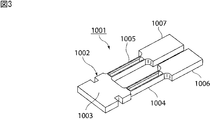
- Patent Document 1 discloses a tuning fork type crystal resonator 1001 shown in FIG.
- the tuning fork type crystal resonator 1001 has a tuning fork type resonator element 1002.
- the tuning fork type vibrating piece 1002 has a base portion 1003.
- One end of vibration arm portions 1004 and 1005 is connected to the base portion 1003.
- Weight portions 1006 and 1007 are connected to the other ends of the vibrating arm portions 1004 and 1005.
- the vibration arm portions 1004 and 1005 are provided with first and second vibration electrodes, respectively. By applying an alternating electric field from the first and second vibrating electrodes, the vibrating arm portions 1004 and 1005 vibrate in the bending mode.
- the tuning fork type crystal resonator 1001 by providing the weight portions 1006 and 1007, the resonance frequency can be lowered and the miniaturization can be promoted.
- the tuning fork type crystal resonator is required to be further downsized.
- a processing method by etching is widely used to form the outer shape of the tuning fork type vibrating piece 1002. That is, a method is generally used in which a quartz substrate is processed by etching to form an outer shape of a tuning fork type vibrating piece.
- An object of the present invention is to provide a tuning fork type crystal resonator in which the variation of the resonance frequency due to variations in processing dimensions is small, and a manufacturing method thereof.
- the tuning fork type crystal resonator according to the present invention includes a tuning fork type vibrating piece and a vibrating electrode.
- the tuning fork-type vibrating piece has a base, a vibrating arm, and a weight.
- the vibration arm portion has a first end portion and a second end portion opposite to the first end portion.
- the vibration arm portion has a first end portion connected to the base portion.
- the weight portion is connected to the second end portion of the vibration arm portion.
- the vibration electrode is provided on the vibration arm portion.
- a plurality of through holes or recesses are provided in the weight portion.
- the weight portion has first and second surfaces facing each other, and the depth direction of the plurality of through holes or recesses is the same as the first surface. This is the direction connecting the second surface.
- a through hole or a recess can be easily formed in the weight portion having the first and second surfaces facing each other.
- the vibrating arm portions are located on both sides in the thickness direction orthogonal to the length direction and the width direction, and are opposed to each other.
- the first surface and the third surface are on the same plane, and the second surface and the fourth surface are on the same plane.
- the weight portion and the vibrating arm portion can be easily formed integrally from one crystal substrate by etching or the like.
- a method for manufacturing a tuning fork type crystal resonator according to the present invention is a method for manufacturing a tuning fork type crystal resonator according to the present invention.
- the method includes a step of preparing a crystal substrate, and a processing of the crystal substrate by etching.
- the tuning fork type crystal resonator according to the present invention since the plurality of through holes or recesses are provided in the weight portion, even if variation in the outer dimensions due to processing occurs, the fluctuation of the resonance frequency is effectively suppressed. Can do.
- FIG. 1A is a perspective view showing an appearance of a tuning fork type crystal resonator according to an embodiment of the present invention
- FIG. 1B is a first vibrating arm in a region where a through hole is provided.
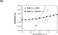
- FIG. FIG. 2 is a diagram illustrating a relationship between a processing dimension shift and a resonance frequency variation in the tuning fork type crystal resonator according to the embodiment of the present invention and the tuning fork type crystal resonator according to the comparative example.
- FIG. 3 is a perspective view showing the appearance of a conventional tuning fork type crystal resonator.
- FIG. 1A is a perspective view showing an appearance of a tuning fork type crystal resonator 1 according to an embodiment of the present invention.
- the tuning fork type crystal resonator 1 includes a tuning fork type vibrating piece 2 and first and second vibrating electrodes 8 and 9.
- the tuning fork type vibrating piece 2 is formed by processing a crystal substrate by etching or the like.
- the tuning fork type vibrating piece 2 has a base 3.
- the base 3 has a substantially rectangular plate shape.
- the shape of the base 3 is not particularly limited.
- First and second vibrating arm portions 4 and 5 are connected to the base portion 3.
- the first vibrating arm portion 4 has a first end portion 4a and a second end portion 4b opposite to the first end portion 4a.
- the first vibrating arm portion 4 is connected to the base portion 3 on the first end portion 4a side.
- the second vibrating arm portion 5 has first and second end portions 5a and 5b.
- the second vibrating arm portion 5 is connected to the base portion 3 on the first end portion 5a side.
- the base portion 3 is provided with L-shaped notches 3a and 3b in plan view.
- the notches 3a and 3b are located outside the portion of the base 3 where the first and second vibrating arm portions 4 and 5 are connected.
- the first vibrating arm portion 4 extends from the end surface 3c side of the base portion 3 toward the second end portion 4b side.
- the second vibrating arm portion 5 extends from the end surface 3 c side of the base portion 3 toward the second end portion 5 b side.
- the first and second vibrating arm portions 4 and 5 have a rod shape.
- the extending direction of the first and second vibrating arm portions 4 and 5 is defined as the length direction. Further, the direction perpendicular to the length direction of the first and second vibrating arm portions 4 and 5 and perpendicular to the thickness direction of the tuning fork type vibrating piece 2 is defined as a width direction.
- the first vibrating arm portion 4 is provided with first and second vibrating electrodes 8 and 9.
- the second vibrating arm unit 5 is also provided with first and second vibrating electrodes 8 and 9.
- weight portions 6 and 7 are connected to the tips of the first and second vibrating arm portions 4 and 5.
- the dimension in the width direction of the weight part 6 is made larger than the dimension in the width direction of the first vibrating arm part 4.
- the resonance frequency is lowered by the mass addition effect by the weight portion 6.
- the weight parts 6 and 7 have first and second surfaces facing each other.
- the weight portion 6 is provided with a plurality of through holes 6a.
- the shape of the plurality of through holes 6a is not particularly limited. In the present embodiment, the plurality of through holes 6a have a rectangular shape in plan view. Moreover, in this embodiment, although the several through-hole 6a is provided, it replaces with the through-hole 6a, and the recessed part which has not penetrated the weight part 6 may be provided.
- the recessed part when the recessed part is provided in the weight part 6, the recessed part may be provided in any of the 1st surface and the 2nd surface of the weight part 6, and is provided in both surfaces of the weight part 6. May be.
- the depth direction of the through hole or the concave portion is a direction connecting the first surface and the second surface. Thereby, the through hole or the recess can be easily formed by etching.
- the weight portion 7 is also provided with a plurality of through holes 7a.
- the plurality of through holes 7a have a rectangular shape in plan view. Also in the weight part 7, it replaces with the through-hole 7a, and the recessed part which does not penetrate the weight part 7 may be provided.
- the first and second vibrating arm portions 4 and 5 are located on both sides in the thickness direction perpendicular to the length direction and the width direction, and have third and fourth surfaces facing each other.
- the first surfaces of the weight portions 6 and 7 and the third surfaces of the first and second vibrating arm portions 4 and 5 are on the same plane.
- the second surfaces of the weight portions 6 and 7 and the fourth surfaces of the first and second vibrating arm portions 4 and 5 are on the same plane.
- the first vibrating arm portion 4 is provided with a through hole 4c extending in the length direction.
- the through hole 4c penetrates from the third surface toward the fourth surface, and has a rectangular shape in plan view.
- a plurality of crosspieces 4d are provided in the through hole 4c for reinforcement.
- the portions located on both sides in the width direction of the through hole 4c in the first vibrating arm portion 4 have the same polarization axis in the direction indicated by the arrow in FIG.
- the first vibration electrode 8 described above is provided on the inner surface of the first vibration arm portion 4 facing the through hole 4c.
- a second vibration electrode 9 is provided on the outer surface of the first vibration arm portion 4 that is located on the opposite side to the inner surface. Therefore, by applying an alternating electric field between the first vibrating electrode 8 and the second vibrating electrode 9, the first vibrating arm portion 4 provided with the through hole 4c is easily vibrated in the bending mode. be able to.
- the second vibrating arm portion 5 is also provided with a through hole and a plurality of crosspieces.
- the portions located on both sides in the width direction of the through hole in the second vibration arm portion 5 are aligned.
- the first vibration electrode 8 is provided on the inner surface facing the through hole in the second vibration arm portion 5, and the second vibration electrode 9 is opposite to the inner surface in the second vibration arm portion 5. Is provided on the outer surface located at Accordingly, by applying an alternating electric field between the first vibrating electrode 8 and the second vibrating electrode 9, the second vibrating arm portion 5 provided with the through hole can be easily vibrated in the bending mode. Can do.
- the first and second vibration arm portions 4 and 5 are provided with through holes.
- the first and second vibration arm portions 4 and 5 have a third surface.
- a concave portion is provided on each of the fourth surfaces, and the cross section may be an H-shaped structure, or the third surface and the fourth surface may be a rectangular parallelepiped structure.
- the resonance frequency of the tuning fork type crystal resonator 1 is F
- the dimension in the length direction of the first and second vibrating arm portions 4 and 5 is L
- the dimension in the width direction is W.
- the following formula (1) is established between F, L, and W.
- the resonance frequency F is lower than the value represented by the expression (1) due to the mass addition effect by the weight portions 6 and 7.
- the quartz substrate is processed by etching or the like to form the outer shape of the tuning fork type vibrating piece 2, a dimensional deviation occurs during the processing.
- the dimension W in the width direction is smaller than the dimension L in the length direction. Therefore, the influence of the dimension shift of the dimension W in the width direction is larger than the shift of the dimension L in the length direction.
- the etching amount tends to be larger or smaller than a desired etching amount.
- the etching amount is excessively large, both the dimension W in the width direction and the dimension L in the length direction become smaller than the target value, and the resonance frequency becomes lower than the desired frequency.
- the etching amount is too small, both the dimension W in the width direction and the dimension L in the length direction are larger than the target value, and the resonance frequency becomes higher than the desired frequency.
- FIG. 2 is a diagram showing a relationship between a machining dimension shift and a resonance frequency variation in the tuning fork crystal resonator 1 according to the embodiment and the tuning fork crystal resonator according to the following comparative example.
- a broken line X in FIG. 2 is a comparative example configured in the same manner as the tuning fork type crystal resonator 1 according to the above embodiment except that the through holes 6a and 7a are not provided in the weight portions 6 and 7.
- the result in the tuning fork type crystal resonator is shown. That is, in FIG. 2, the horizontal axis indicates the size of the processing dimension deviation due to etching, and the vertical axis indicates the amount of frequency fluctuation, that is, the amount of fluctuation of the resonance frequency from a desired frequency.
- the resonance frequency decreases as the processing dimension deviation becomes negative and the absolute value increases, that is, as the etching amount increases and the width dimension W and the length dimension L decrease. Become.
- the resonance frequency increases as the processing dimension deviation is a positive value and the absolute value increases, that is, as the etching amount becomes insufficient and the dimension W in the width direction and the dimension L in the length direction increase.
- the solid line Y in FIG. 2 shows the result in the tuning fork type crystal resonator 1 according to the above embodiment. As shown by the solid line Y in FIG. 2, even if the etching amount changes and a processing dimension shift occurs, it can be seen that the tuning fork crystal resonator 1 according to the present embodiment has a small variation in the resonance frequency. This is due to the following reason.
- the mass addition effect by the weight portions 6 and 7 also varies depending on the etching amount. For this reason, fluctuations in the resonance frequency can be reduced. More specifically, when the etching amount increases, the dimension W in the width direction and the dimension L in the length direction become smaller, and the resonance frequency is lowered. However, the through-holes 6a and 7a provided in the weight parts 6 and 7 are large, so that the mass addition effect by the weight parts 6 and 7 is reduced and the resonance frequency is increased. Therefore, the fluctuation of the resonance frequency becomes small.
- the etching amount when the etching amount is insufficient, the dimension W in the width direction and the dimension L in the length direction are increased, and the resonance frequency is increased.
- the through-holes 6a and 7a provided in the weight portions 6 and 7 are reduced, and the mass addition effect by the weight portions 6 and 7 is increased, and the resonance frequency is lowered. Therefore, the fluctuation of the resonance frequency becomes small.
- the change in the dimension W in the width direction and the change in the dimension L in the length direction due to the change in the etching amount in particular, the variation direction of the resonance frequency based on the change in the dimension W in the width direction, and the weight portion due to the change in the etching amount
- This is the direction opposite to the fluctuation direction of the resonance frequency due to the mass addition effect based on. Accordingly, it is possible to suppress fluctuations in the resonance frequency due to deviations in outer dimensions due to variations in etching amount, that is, variations in processing.
- the quartz substrate is etched to form the outer shape of the tuning fork type vibrating piece 2, that is, the outer shape including the shapes of the through holes 6a and 7a. be able to.
- the tuning fork type resonator element 2 is obtained by processing the quartz substrate by etching. Therefore, in the present embodiment, the first surfaces of the weight portions 6 and 7 and the third surfaces of the first and second vibrating arm portions 4 and 5 are on the same plane, and the first surfaces of the weight portions 6 and 7 are the same. Since the second surface and the fourth surfaces of the first and second vibrating arm portions 4 and 5 are on the same plane, the first and second of the same thickness can be obtained by processing one quartz substrate.
- the tuning fork type vibrating piece 2 having the vibrating arm portions 4 and 5 and the weight portions 6 and 7 can be easily obtained.
- the thicknesses of the weight parts 6 and 7 may be different from the thicknesses of the first and second vibrating arm parts 4 and 5.
- the through holes 6a and 7a are simultaneously and easily formed by the same etching process. be able to. Therefore, it is preferable that the first surface and the third surface are on the same plane, and the second surface and the fourth surface are on the same plane.
- the manufacturing method of the tuning fork type crystal resonator 1 is not particularly limited, but the following method can be preferably used. First, a quartz substrate is prepared. Thereafter, the crystal substrate is processed by etching to form the outer shape of the tuning fork type vibrating piece 2. In this case, as described above, even if the etching amount varies and the outer shape of the tuning fork type vibrating piece 2 deviates from the target dimension, the fluctuation of the resonance frequency can be suppressed according to the present invention.
- the first and second vibrating arms 8 and 9 are formed on the first and second vibrating arms 4 and 5 by a known method such as vapor deposition, plating, or sputtering. Form using method. In this way, the tuning fork type crystal resonator 1 can be obtained.
- the outer shape of the tuning fork type resonator element 2 of the tuning fork type crystal resonator 1 may be formed by a method other than etching.
Landscapes
- Chemical & Material Sciences (AREA)
- Crystallography & Structural Chemistry (AREA)
- Physics & Mathematics (AREA)
- Acoustics & Sound (AREA)
- Piezo-Electric Or Mechanical Vibrators, Or Delay Or Filter Circuits (AREA)
Description
本発明は、水晶を用いた音叉型水晶振動子及びその製造方法に関し、特に、振動アーム部先端に錘部が設けられている音叉型水晶振動子及びその製造方法に関する。
従来、発振子等に音叉型水晶振動子が広く用いられている。下記の特許文献1には、図3に示す音叉型水晶振動子1001が開示されている。
音叉型水晶振動子1001は、音叉型振動片1002を有する。音叉型振動片1002は、基部1003を有する。基部1003に、振動アーム部1004,1005の一端が連ねられている。振動アーム部1004,1005の他端には、錘部1006,1007が連ねられている。振動アーム部1004,1005には、それぞれ、第1,第2の振動電極が設けられている。第1,第2の振動電極から交番電界を印加することにより、振動アーム部1004,1005が屈曲モードで振動する。
音叉型水晶振動子1001では、錘部1006,1007を設けたことにより共振周波数を低めることができ、小型化を進めることが可能とされている。しかしながら、音叉型水晶振動子では、更なる小型化が求められている。
小型化に伴って、音叉型振動片1002の外形を形成するためにエッチングによる加工方法が広く用いられている。すなわち、水晶基板をエッチングにより加工し、音叉型振動片の外形を形成する方法が一般的に用いられている。
しかしながら、更なる小型化を果たすために、音叉型振動片の外形寸法が小さくなると、加工寸法のばらつきによる共振周波数の変動が大きくなるという問題があった。
本発明の目的は、加工寸法のばらつきによる共振周波数の変動が小さい音叉型水晶振動子及びその製造方法を提供することにある。
本発明に係る音叉型水晶振動子は、音叉型振動片と、振動電極とを備える。音叉型振動片は、基部と、振動アーム部と、錘部とを有する。振動アーム部は、第1の端部と第1の端部とは反対側の第2の端部とを有する。振動アーム部は、第1の端部が基部に連ねられている。錘部は、振動アーム部の第2の端部に連ねられている。振動アーム部の第1,第2の端部を結ぶ方向を長さ方向とし、長さ方向と直交する方向を幅方向としたときに、錘部の幅方向の寸法が、振動アーム部の幅方向の寸法よりも大きい。振動電極は、振動アーム部に設けられている。錘部に、複数の貫通孔または凹部が設けられている。
本発明の音叉型水晶振動子のある特定の局面では、錘部が、対向し合う第1,第2の面を有し、複数の貫通孔または凹部の深さ方向が、第1の面と第2の面とを結ぶ方向である。この場合には、対向しあう第1,第2の面を有する錘部に、貫通孔または凹部を容易に形成することができる。
また、本発明に係る音叉型水晶振動子の他の特定の居面では、振動アーム部が、長さ方向及び幅方向と直交する厚み方向の両側に位置しており、互いに対向している第3及び第4の面を有し、第1の面と第3の面とは同一平面上にあり、第2の面と第4の面とは同一平面上にある。この場合には、1つの水晶基板からエッチング等により、錘部と振動アーム部とを一体的に容易に形成することができる。
本発明に係る音叉型水晶振動子の製造方法は、本発明にしたがって構成された音叉型水晶振動子の製造方法であり、水晶基板を用意する工程と、エッチングにより水晶基板を加工し、音叉型振動片の外形を形成する工程と、振動アーム部に振動電極を形成する工程とを備える。
本発明に係る音叉型水晶振動子では、錘部に複数の貫通孔または凹部が設けられているため、加工による外形寸法のばらつきが生じたとしても、共振周波数の変動を効果的に抑制することができる。
以下、図面を参照しつつ、本発明の具体的な実施形態を説明することにより、本発明を明らかにする。
図1(a)は、本発明の一実施形態に係る音叉型水晶振動子1の外観を示す斜視図である。
音叉型水晶振動子1は、音叉型振動片2と、第1,第2の振動電極8,9とを有する。
音叉型振動片2は、水晶基板をエッチング等により加工することにより形成されている。音叉型振動片2は、基部3を有する。基部3は略矩形板状の形状を有する。もっとも基部3の形状は特に限定されるものではない。
基部3に、第1,第2の振動アーム部4,5が連ねられている。第1の振動アーム部4は、第1の端部4aと、第1の端部4aとは反対側の第2の端部4bとを有する。第1の端部4a側において、第1の振動アーム部4は基部3に連ねられている。第2の振動アーム部5も同様に、第1,第2の端部5a,5bを有する。第2の振動アーム部5は、第1の端部5a側において、基部3に連ねられている。
第1,第2の振動アーム部4,5の変位を大きくするために、基部3には、平面視してL字状の切欠3a,3bが設けられている。切欠3a,3bは、基部3の第1,第2の振動アーム部4,5が連ねられている部分の外側に位置している。
第1の振動アーム部4は、基部3の端面3c側から第2の端部4b側に向かって延ばされている。第2の振動アーム部5は、基部3の端面3c側から第2の端部5b側に向かって延ばされている。第1,第2の振動アーム部4,5は棒状の形状を有する。
ここで、第1,第2の振動アーム部4,5の延びる方向を長さ方向とする。また、第1,第2の振動アーム部4,5の長さ方向と直交する方向であって、音叉型振動片2の厚み方向と直交する方向を幅方向とする。
第1の振動アーム部4には、第1,第2の振動電極8,9が設けられている。第2の振動アーム部5にも、第1,第2の振動電極8,9が設けられている。
また、第1,第2の振動アーム部4,5の先端には、錘部6,7が連ねられている。錘部6の幅方向の寸法は、第1の振動アーム部4の幅方向の寸法よりも大きくされている。錘部6による質量付加効果により、共振周波数が低められている。錘部6,7は、対向し合う第1,第2の面を有する。
加えて、本実施形態では、錘部6に、複数の貫通孔6aが設けられている。複数の貫通孔6aの形状は特に限定されるものではない。本実施形態では、複数の貫通孔6aは、平面視して矩形の形状とされている。また、本実施形態では、複数の貫通孔6aが設けられているが、貫通孔6aに代えて、錘部6を貫通していない凹部が設けられていてもよい。
なお、錘部6に凹部が設けられている場合、凹部は錘部6の第1の面及び第2の面のいずれに設けられていてもよく、錘部6の双方の面に設けられていてもよい。いずれにしても、錘部6において、貫通孔や凹部の深さ方向は、上記第1の面と第2の面とを結ぶ方向であることが望ましい。それによって、エッチングにより貫通孔または凹部を容易に形成することができる。
錘部7にも、複数の貫通孔7aが設けられている。本実施形態では、複数の貫通孔7aは、平面視して矩形の形状とされている。錘部7においても、貫通孔7aに代えて、錘部7を貫通していない凹部が設けられていてもよい。
第1,第2の振動アーム部4,5は、長さ方向及び幅方向と直交する厚み方向の両側に位置しており、互いに対向している第3及び第4の面を有する。錘部6,7の第1の面と、第1,第2の振動アーム部4,5の第3の面とは、同一平面上にある。錘部6,7の第2の面と、第1,第2の振動アーム部4,5の第4の面とは、同一平面上にある。
第1の振動アーム部4には、長さ方向に延びる貫通孔4cが設けられている。貫通孔4cは、上記第3の面から第4の面に向かって貫通しており、平面視して矩形の形状とされている。貫通孔4cには補強のために複数本の桟4dが設けられている。第1の振動アーム部4における貫通孔4cの幅方向両側に位置する部分は、図1(b)に矢印で示す方向に分極軸が揃っている。また前述した第1の振動電極8は、第1の振動アーム部4における貫通孔4cに臨む内側面に設けられている。他方、第1の振動アーム部4における内側面とは反対側に位置している外側面に、第2の振動電極9が設けられている。従って、第1の振動電極8と第2の振動電極9との間に交番電界を印加することにより、貫通孔4cが設けられている第1の振動アーム部4を屈曲モードで容易に振動させることができる。
第2の振動アーム部5についても同様に、貫通孔と複数本の桟とが設けられている。また、第2の振動アーム部5における貫通孔の幅方向両側に位置する部分は、第1の振動アーム部4と同様に、分極軸が揃っている。また、第1の振動電極8が第2の振動アーム部5における貫通孔に臨む内側面に設けられており、第2の振動電極9が第2の振動アーム部5における内側面とは反対側に位置している外側面に設けられている。従って、第1の振動電極8と第2の振動電極9との間に交番電界を印加することにより、貫通孔が設けられている第2の振動アーム部5を屈曲モードで容易に振動させることができる。
なお、本実施形態では、第1,第2の振動アーム部4,5に貫通孔が設けられている構造であるが、第1,第2の振動アーム部4,5は第3の面と第4の面のそれぞれに凹部が設けられおり、断面はH型である構造であってもよく、第3の面と第4の面が平坦な直方体形状の構造であってもよい。
本実施形態の音叉型水晶振動子1では、上記錘部6,7に貫通孔6a,7aが設けられているため、共振周波数のばらつきを低減することができる。これを以下において詳述する。
音叉型水晶振動子1の共振周波数をF、第1,第2の振動アーム部4,5の長さ方向の寸法をL、幅方向の寸法をWとする。この場合、F、L及びWとの間には、下記の式(1)が成り立つ。
F=a(W/ L2)×(C′22/ρ)1/2 …(1)
C´22は弾性スティフネス定数、ρは水晶の密度、aは比例定数を示す。
C´22は弾性スティフネス定数、ρは水晶の密度、aは比例定数を示す。
上記錘部6,7が設けられている音叉型水晶振動子1では、錘部6,7による質量付加効果によって共振周波数Fが式(1)に表わされる値よりも低くなる。
他方、エッチングなどにより水晶基板を加工し、音叉型振動片2の外形を形成した場合、加工の際に寸法ずれが生じる。第1,第2の振動アーム部4,5では、長さ方向の寸法Lよりも幅方向の寸法Wの方が小さい。従って、長さ方向の寸法Lのずれよりも幅方向の寸法Wの寸法ずれの影響が大きい。
一般に、水晶基板をエッチングして音叉型振動片を得るにあたっては、所望のエッチング量よりもエッチング量が多くなったり、少なくなったりしがちである。エッチング量が多くなりすぎると、幅方向の寸法W及び長さ方向の寸法Lのいずれもが、目標の値よりも小さくなり、共振周波数は所望の周波数よりも低くなる。これに対して、エッチング量が少なすぎた場合には、幅方向の寸法W及び長さ方向の寸法Lがいずれも目標値よりも大きくなり、共振周波数は所望の周波数よりも高くなる。
図2は、上記実施形態に係る音叉型水晶振動子1及び下記の比較例に係る音叉型水晶振動子における加工寸法ずれと、共振周波数の変動量との関係を示す図である。
図2の破線Xは、上記錘部6,7に貫通孔6a,7aが設けられていないことを除いては、上記実施形態に係る音叉型水晶振動子1と同様にして構成した比較例に係る音叉型水晶振動子における結果を示す。すなわち、図2において、横軸はエッチングによる加工寸法ずれの大きさを示し、縦軸は周波数変動の量、すなわち、共振周波数の所望の周波数からの変動量を示す。破線Xから明らかなように、加工寸法ずれが負の値で絶対値が大きくなるほど、すなわち、エッチング量が増大し、幅方向の寸法W及び長さ方向の寸法Lが小さくなるほど、共振周波数は低くなる。これに対して、加工寸法ずれが正の値で絶対値が大きくなるほど、すなわち、エッチング量が不足し、幅方向の寸法W及び長さ方向の寸法Lが大きくなるほど、共振周波数が高くなる。
図2の実線Yは、上記実施形態に係る音叉型水晶振動子1における結果を示す。図2の実線Yで示すように、エッチング量が変化して加工寸法ずれが生じたとしても、本実施形態に係る音叉型水晶振動子1では、共振周波数の変動が小さいことがわかる。これは、以下の理由による。
本実施形態のように錘部6,7に貫通孔6a,7aが設けられている構造では、錘部6,7による質量付加効果もエッチング量によって変化する。そのため、共振周波数の変動を小さくすることができる。より詳しくは、エッチング量が増大すると、幅方向の寸法Wや長さ方向の寸法Lが小さくなり、共振周波数が低くなるように作用する。しかしながら、錘部6,7に設けられている貫通孔6a,7aは大きくなり、錘部6,7による質量付加効果が小さくなり、共振周波数が高くなるように作用する。従って、共振周波数の変動は小さくなる。これに対して、エッチング量が不足すると、幅方向の寸法Wや長さ方向の寸法Lが大きくなり、共振周波数は高くなるように作用する。しかしながら、錘部6,7に設けられている貫通孔6a,7aが小さくなり、錘部6,7による質量付加効果が大きくなり、共振周波数が低くなるように作用する。従って、共振周波数の変動は小さくなる。
上記のように、エッチング量の変化による幅方向の寸法Wや長さ方向の寸法Lの変化、特には幅方向の寸法Wの変化に基づく共振周波数の変動方向と、エッチング量の変化による錘部に基づく質量付加効果による共振周波数の変動方向とは逆方向となる。従って、エッチング量のばらつきすなわち加工ばらつきによる外形寸法のずれによる共振周波数の変動を抑制することができる。
また、上記実施形態では、水晶基板をエッチングすることにより、音叉型振動片2の外形すなわち貫通孔6a,7aの形状を含む外形を形成しているため、上記のとおり共振周波数の変動を抑制することができる。
なお、本実施形態では、水晶基板をエッチングにより加工することにより音叉型振動片2が得られている。従って、本実施形態では、錘部6,7の第1の面と第1,第2の振動アーム部4,5の第3の面とが同一平面上にあり、錘部6,7の第2の面と第1,第2の振動アーム部4,5の第4の面とが同一平面上にあるため、1枚の水晶基板を加工することにより、同じ厚みの第1,第2の振動アーム部4,5及び錘部6,7を有する音叉型振動片2を容易に得ることができる。
なお、本発明においては、錘部6,7の厚みは、第1,第2の振動アーム部4,5の厚みと異なっていてもよい。もっとも、上記のようにエッチングにより錘部6,7を第1,第2の振動アーム部4,5と同時に形成する場合には、貫通孔6a,7aを同じエッチング工程により同時にかつ容易に形成することができる。従って、第1の面と第3の面とが同一平面上にあり、第2の面と第4の面とが同一平面上にあることが好ましい。
上記音叉型水晶振動子1の製造法については、特に限定されないが、以下の方法を好適に用いることができる。まず、水晶基板を用意する。しかる後、この水晶基板をエッチングにより加工し、音叉型振動片2の外形を形成する。この場合、上記のとおり、エッチング量にばらつきが生じ、音叉型振動片2の外形が目的とする寸法からずれたとしても、本発明にしたがって共振周波数の変動を抑制することができる。
上記音叉型振動片2の外形を形成した後、第1,第2の振動アーム部4,5に第1,第2の振動電極8,9を蒸着法、めっき法もしくはスパッタリング法などの周知の方法を用いて形成する。このようにして、音叉型水晶振動子1を得ることができる。なお、音叉型水晶振動子1の音叉型振動片2の外形はエッチング以外の方法より形成されていてもよい。
1…音叉型水晶振動子
2…音叉型振動片
3…基部
3a,3b…切欠
3c…端面
4…第1の振動アーム部
4a…第1の端部
4b…第2の端部
4c…貫通孔
4d…桟
5…第2の振動アーム部
5a…第1の端部
5b…第2の端部
6,7…錘部
6a,7a…貫通孔
8…第1の振動電極
9…第2の振動電極
2…音叉型振動片
3…基部
3a,3b…切欠
3c…端面
4…第1の振動アーム部
4a…第1の端部
4b…第2の端部
4c…貫通孔
4d…桟
5…第2の振動アーム部
5a…第1の端部
5b…第2の端部
6,7…錘部
6a,7a…貫通孔
8…第1の振動電極
9…第2の振動電極
Claims (4)
- 基部と、第1の端部と前記第1の端部とは反対側の第2の端部とを有し、前記第1の端部が前記基部に連ねられている振動アーム部と、前記振動アーム部の前記第2の端部に連ねられており、前記振動アーム部の第1,第2の端部を結ぶ方向を長さ方向とし、長さ方向と直交する方向を幅方向としたときに、前記幅方向の寸法が、前記振動アーム部の幅方向の寸法よりも大きい錘部とを有する音叉型振動片と、
前記振動アーム部に設けられている振動電極とを備え、
前記錘部に、複数の貫通孔または凹部が設けられている、音叉型水晶振動子。 - 前記錘部が、対向し合う第1,第2の面を有し、前記複数の貫通孔または凹部の深さ方向が、前記第1の面と第2の面とを結ぶ方向である、請求項1に記載の音叉型水晶振動子。
- 前記振動アーム部が、前記長さ方向及び前記幅方向と直交する厚み方向の両側に位置しており、互いに対向している第3及び第4の面を有し、前記第1の面と前記第3の面とは同一平面上にあり、前記第2の面と前記第4の面とは同一平面上にある、請求項2に記載の音叉型水晶振動子。
- 請求項1~3のいずれか1項に記載の音叉型水晶振動子の製造方法であって、
水晶基板を用意する工程と、
エッチングにより水晶基板を加工し、前記音叉型振動片の外形を形成する工程と、
前記振動アーム部に前記振動電極を形成する工程とを備える、音叉型水晶振動子の製造方法。
Priority Applications (1)
| Application Number | Priority Date | Filing Date | Title |
|---|---|---|---|
| JP2014522590A JPWO2014002891A1 (ja) | 2012-06-27 | 2013-06-21 | 音叉型水晶振動子及びその製造方法 |
Applications Claiming Priority (2)
| Application Number | Priority Date | Filing Date | Title |
|---|---|---|---|
| JP2012143786 | 2012-06-27 | ||
| JP2012-143786 | 2012-06-27 |
Publications (1)
| Publication Number | Publication Date |
|---|---|
| WO2014002891A1 true WO2014002891A1 (ja) | 2014-01-03 |
Family
ID=49783046
Family Applications (1)
| Application Number | Title | Priority Date | Filing Date |
|---|---|---|---|
| PCT/JP2013/067080 Ceased WO2014002891A1 (ja) | 2012-06-27 | 2013-06-21 | 音叉型水晶振動子及びその製造方法 |
Country Status (2)
| Country | Link |
|---|---|
| JP (1) | JPWO2014002891A1 (ja) |
| WO (1) | WO2014002891A1 (ja) |
Cited By (2)
| Publication number | Priority date | Publication date | Assignee | Title |
|---|---|---|---|---|
| US20160006411A1 (en) * | 2014-07-07 | 2016-01-07 | Samsung Electro-Mechanics Co., Ltd. | Tuning fork and electronic device using the same |
| CN117767908A (zh) * | 2023-12-27 | 2024-03-26 | 天津大学 | 一种音叉型压电振动片及振荡器 |
Citations (5)
| Publication number | Priority date | Publication date | Assignee | Title |
|---|---|---|---|---|
| JP2004282230A (ja) * | 2003-03-13 | 2004-10-07 | Seiko Epson Corp | 圧電振動片、及びこれを利用した圧電デバイス、並びにこれを利用した携帯電話装置、電子機器 |
| JP2005005896A (ja) * | 2003-06-10 | 2005-01-06 | Seiko Epson Corp | 圧電振動片、圧電振動片の製造方法および圧電振動子、圧電振動子を搭載した電子機器 |
| JP2008085768A (ja) * | 2006-09-28 | 2008-04-10 | Nippon Dempa Kogyo Co Ltd | 音叉型水晶振動素子及びその製造方法 |
| JP2011250225A (ja) * | 2010-05-28 | 2011-12-08 | Nippon Dempa Kogyo Co Ltd | 圧電デバイス、および圧電デバイスの周波数調整方法 |
| JP2012120014A (ja) * | 2010-12-02 | 2012-06-21 | Seiko Epson Corp | 圧電振動素子、その製造方法、圧電振動子及び圧電発振器 |
-
2013
- 2013-06-21 WO PCT/JP2013/067080 patent/WO2014002891A1/ja not_active Ceased
- 2013-06-21 JP JP2014522590A patent/JPWO2014002891A1/ja active Pending
Patent Citations (5)
| Publication number | Priority date | Publication date | Assignee | Title |
|---|---|---|---|---|
| JP2004282230A (ja) * | 2003-03-13 | 2004-10-07 | Seiko Epson Corp | 圧電振動片、及びこれを利用した圧電デバイス、並びにこれを利用した携帯電話装置、電子機器 |
| JP2005005896A (ja) * | 2003-06-10 | 2005-01-06 | Seiko Epson Corp | 圧電振動片、圧電振動片の製造方法および圧電振動子、圧電振動子を搭載した電子機器 |
| JP2008085768A (ja) * | 2006-09-28 | 2008-04-10 | Nippon Dempa Kogyo Co Ltd | 音叉型水晶振動素子及びその製造方法 |
| JP2011250225A (ja) * | 2010-05-28 | 2011-12-08 | Nippon Dempa Kogyo Co Ltd | 圧電デバイス、および圧電デバイスの周波数調整方法 |
| JP2012120014A (ja) * | 2010-12-02 | 2012-06-21 | Seiko Epson Corp | 圧電振動素子、その製造方法、圧電振動子及び圧電発振器 |
Cited By (2)
| Publication number | Priority date | Publication date | Assignee | Title |
|---|---|---|---|---|
| US20160006411A1 (en) * | 2014-07-07 | 2016-01-07 | Samsung Electro-Mechanics Co., Ltd. | Tuning fork and electronic device using the same |
| CN117767908A (zh) * | 2023-12-27 | 2024-03-26 | 天津大学 | 一种音叉型压电振动片及振荡器 |
Also Published As
| Publication number | Publication date |
|---|---|
| JPWO2014002891A1 (ja) | 2016-05-30 |
Similar Documents
| Publication | Publication Date | Title |
|---|---|---|
| JP5155275B2 (ja) | 音叉型圧電振動片、圧電フレーム及び圧電デバイス | |
| US8053958B2 (en) | Piezoelectric resonator element, piezoelectric resonator, and acceleration sensor | |
| JP5089298B2 (ja) | 音叉型屈曲振動子 | |
| JP2007124441A (ja) | メサ型圧電振動片 | |
| JP2017085341A5 (ja) | ||
| JP4593203B2 (ja) | 音叉型水晶振動子及びその製造方法 | |
| JP5402031B2 (ja) | 水晶振動片の加工方法及び水晶ウェーハ | |
| US9819328B2 (en) | Tuning-fork type quartz vibrator | |
| JP2010232932A5 (ja) | 振動片 | |
| JP2011024225A5 (ja) | 水晶振動子と水晶ユニットと水晶発振器と情報通信機器及びそれらの 製造方法 | |
| WO2014002891A1 (ja) | 音叉型水晶振動子及びその製造方法 | |
| JP2017034667A (ja) | 圧電振動片および圧電振動子 | |
| JPWO2016114237A1 (ja) | 共振子 | |
| JP5399888B2 (ja) | 音叉型屈曲水晶振動素子 | |
| JP2003060482A (ja) | 音叉型水晶振動片 | |
| JP5973212B2 (ja) | 音叉型圧電振動子の製造方法 | |
| WO2014002892A1 (ja) | 音叉型水晶振動子 | |
| US20160182012A1 (en) | Tuning fork vibrator | |
| JP6007810B2 (ja) | 音叉型水晶振動子及びその製造方法 | |
| TWI705662B (zh) | 小的壓電共振器 | |
| JP6525821B2 (ja) | 音叉型水晶素子 | |
| JP4281451B2 (ja) | 圧電振動片および圧電振動子 | |
| JP6087527B2 (ja) | 音叉型水晶振動子 | |
| JP2017158146A (ja) | 水晶振動子 | |
| JP6111539B2 (ja) | 水晶振動子 |
Legal Events
| Date | Code | Title | Description |
|---|---|---|---|
| 121 | Ep: the epo has been informed by wipo that ep was designated in this application |
Ref document number: 13809359 Country of ref document: EP Kind code of ref document: A1 |
|
| ENP | Entry into the national phase |
Ref document number: 2014522590 Country of ref document: JP Kind code of ref document: A |
|
| NENP | Non-entry into the national phase |
Ref country code: DE |
|
| 122 | Ep: pct application non-entry in european phase |
Ref document number: 13809359 Country of ref document: EP Kind code of ref document: A1 |