WO2013190926A1 - 貼付装置 - Google Patents
貼付装置 Download PDFInfo
- Publication number
- WO2013190926A1 WO2013190926A1 PCT/JP2013/062816 JP2013062816W WO2013190926A1 WO 2013190926 A1 WO2013190926 A1 WO 2013190926A1 JP 2013062816 W JP2013062816 W JP 2013062816W WO 2013190926 A1 WO2013190926 A1 WO 2013190926A1
- Authority
- WO
- WIPO (PCT)
- Prior art keywords
- plate
- support
- substrate
- plate member
- laminate
- Prior art date
- Legal status (The legal status is an assumption and is not a legal conclusion. Google has not performed a legal analysis and makes no representation as to the accuracy of the status listed.)
- Ceased
Links
Images
Classifications
-
- H—ELECTRICITY
- H01—ELECTRIC ELEMENTS
- H01L—SEMICONDUCTOR DEVICES NOT COVERED BY CLASS H10
- H01L21/00—Processes or apparatus adapted for the manufacture or treatment of semiconductor or solid state devices or of parts thereof
- H01L21/67—Apparatus specially adapted for handling semiconductor or electric solid state devices during manufacture or treatment thereof; Apparatus specially adapted for handling wafers during manufacture or treatment of semiconductor or electric solid state devices or components ; Apparatus not specifically provided for elsewhere
- H01L21/683—Apparatus specially adapted for handling semiconductor or electric solid state devices during manufacture or treatment thereof; Apparatus specially adapted for handling wafers during manufacture or treatment of semiconductor or electric solid state devices or components ; Apparatus not specifically provided for elsewhere for supporting or gripping
- H01L21/6835—Apparatus specially adapted for handling semiconductor or electric solid state devices during manufacture or treatment thereof; Apparatus specially adapted for handling wafers during manufacture or treatment of semiconductor or electric solid state devices or components ; Apparatus not specifically provided for elsewhere for supporting or gripping using temporarily an auxiliary support
-
- H—ELECTRICITY
- H01—ELECTRIC ELEMENTS
- H01L—SEMICONDUCTOR DEVICES NOT COVERED BY CLASS H10
- H01L21/00—Processes or apparatus adapted for the manufacture or treatment of semiconductor or solid state devices or of parts thereof
- H01L21/67—Apparatus specially adapted for handling semiconductor or electric solid state devices during manufacture or treatment thereof; Apparatus specially adapted for handling wafers during manufacture or treatment of semiconductor or electric solid state devices or components ; Apparatus not specifically provided for elsewhere
- H01L21/683—Apparatus specially adapted for handling semiconductor or electric solid state devices during manufacture or treatment thereof; Apparatus specially adapted for handling wafers during manufacture or treatment of semiconductor or electric solid state devices or components ; Apparatus not specifically provided for elsewhere for supporting or gripping
-
- B—PERFORMING OPERATIONS; TRANSPORTING
- B32—LAYERED PRODUCTS
- B32B—LAYERED PRODUCTS, i.e. PRODUCTS BUILT-UP OF STRATA OF FLAT OR NON-FLAT, e.g. CELLULAR OR HONEYCOMB, FORM
- B32B37/00—Methods or apparatus for laminating, e.g. by curing or by ultrasonic bonding
- B32B37/0046—Methods or apparatus for laminating, e.g. by curing or by ultrasonic bonding characterised by constructional aspects of the apparatus
-
- H—ELECTRICITY
- H01—ELECTRIC ELEMENTS
- H01L—SEMICONDUCTOR DEVICES NOT COVERED BY CLASS H10
- H01L21/00—Processes or apparatus adapted for the manufacture or treatment of semiconductor or solid state devices or of parts thereof
- H01L21/67—Apparatus specially adapted for handling semiconductor or electric solid state devices during manufacture or treatment thereof; Apparatus specially adapted for handling wafers during manufacture or treatment of semiconductor or electric solid state devices or components ; Apparatus not specifically provided for elsewhere
- H01L21/67005—Apparatus not specifically provided for elsewhere
- H01L21/67011—Apparatus for manufacture or treatment
- H01L21/67092—Apparatus for mechanical treatment
-
- H—ELECTRICITY
- H01—ELECTRIC ELEMENTS
- H01L—SEMICONDUCTOR DEVICES NOT COVERED BY CLASS H10
- H01L21/00—Processes or apparatus adapted for the manufacture or treatment of semiconductor or solid state devices or of parts thereof
- H01L21/67—Apparatus specially adapted for handling semiconductor or electric solid state devices during manufacture or treatment thereof; Apparatus specially adapted for handling wafers during manufacture or treatment of semiconductor or electric solid state devices or components ; Apparatus not specifically provided for elsewhere
- H01L21/67005—Apparatus not specifically provided for elsewhere
- H01L21/67242—Apparatus for monitoring, sorting or marking
- H01L21/67288—Monitoring of warpage, curvature, damage, defects or the like
-
- B—PERFORMING OPERATIONS; TRANSPORTING
- B32—LAYERED PRODUCTS
- B32B—LAYERED PRODUCTS, i.e. PRODUCTS BUILT-UP OF STRATA OF FLAT OR NON-FLAT, e.g. CELLULAR OR HONEYCOMB, FORM
- B32B2457/00—Electrical equipment
- B32B2457/14—Semiconductor wafers
-
- B—PERFORMING OPERATIONS; TRANSPORTING
- B32—LAYERED PRODUCTS
- B32B—LAYERED PRODUCTS, i.e. PRODUCTS BUILT-UP OF STRATA OF FLAT OR NON-FLAT, e.g. CELLULAR OR HONEYCOMB, FORM
- B32B37/00—Methods or apparatus for laminating, e.g. by curing or by ultrasonic bonding
- B32B37/10—Methods or apparatus for laminating, e.g. by curing or by ultrasonic bonding characterised by the pressing technique, e.g. using action of vacuum or fluid pressure
-
- B—PERFORMING OPERATIONS; TRANSPORTING
- B32—LAYERED PRODUCTS
- B32B—LAYERED PRODUCTS, i.e. PRODUCTS BUILT-UP OF STRATA OF FLAT OR NON-FLAT, e.g. CELLULAR OR HONEYCOMB, FORM
- B32B37/00—Methods or apparatus for laminating, e.g. by curing or by ultrasonic bonding
- B32B37/12—Methods or apparatus for laminating, e.g. by curing or by ultrasonic bonding characterised by using adhesives
-
- B—PERFORMING OPERATIONS; TRANSPORTING
- B32—LAYERED PRODUCTS
- B32B—LAYERED PRODUCTS, i.e. PRODUCTS BUILT-UP OF STRATA OF FLAT OR NON-FLAT, e.g. CELLULAR OR HONEYCOMB, FORM
- B32B41/00—Arrangements for controlling or monitoring lamination processes; Safety arrangements
Definitions
- the present invention relates to a pasting device for pasting a substrate and a support through an adhesive layer by applying a pressing force.
- Patent Document 1 discloses an inorganic substrate made of a semiconductor or ceramics between a pair of upper and lower heating plates heated to a predetermined temperature in a vacuum press. After installing the combination set of the laminated material and the auxiliary material for lamination processing and bringing the pair of hot plates into contact with the combination set, a low pressure load of at least 0.05 MPa from the start of pressurization is 10 seconds or more. The method of pressing an inorganic substrate is described.
- the pasting device applies the pressing force to a laminate formed by laminating a substrate, an adhesive layer, and a support that supports the substrate in this order.
- a sticking device for attaching a substrate and a support through an adhesive layer comprising a pair of plate members that sandwich the laminate and apply a pressing force to the laminate, and a support member that supports the plate member,
- a portion of the plate member in contact with the laminate is made of ceramics, and the plate member has a flatness when the portion in contact with the laminate is not pressed is 1.0 ⁇ m or less.
- the portion of the plate member that contacts the laminate is made of ceramics, and the plate member has a flatness of 1.0 ⁇ m or less when the portion that contacts the laminate is not pressed. The possibility of sometimes damaging the substrate can be avoided. Therefore, it is possible to provide a sticking device that can evenly stick the substrate and the support through the adhesive layer.
- the sticking device applies a pressing force to a laminate formed by laminating a substrate, an adhesive layer, and a support that supports the substrate in this order, thereby attaching the adhesive layer to the substrate and the support.
- a pair of plate members that sandwich the laminated body and apply a pressing force to the laminated body, and a support member that supports the plate member, and a portion that contacts the laminated body in the plate member Is made of ceramics, and the plate member has a configuration in which the flatness of the portion in contact with the laminated body when not pressed is 1.0 ⁇ m or less.
- the laminate to be affixed is formed by laminating a substrate, an adhesive layer containing, for example, a thermoplastic resin, and a support plate (support) that supports the substrate in this order. That is, the laminate is formed by laminating the substrate, the adhesive layer, and the support plate in this order by applying an adhesive to either the substrate or the support plate. And after a laminated body is laminated
- the forming method and forming apparatus for forming the laminate that is, the method for forming the adhesive layer and the adhesive layer forming apparatus, and the method for overlaying the substrate and the support plate and the overlay apparatus are not particularly limited, Various methods and apparatuses can be employed.
- the adhesive layer can be formed by attaching an adhesive tape to which an adhesive is applied to either the substrate or the support plate.
- the laminated body only needs to be formed by laminating the substrate, the adhesive layer, and the support plate in this order when the pressing force is applied by the sticking device.
- the substrate is subjected to processes such as thinning, transporting, and mounting while being supported (attached) to the support plate.
- the substrate is not limited to a wafer substrate, and may be any substrate such as a ceramic substrate, a thin film substrate, or a flexible substrate that needs to be supported by a support plate.
- the support plate is a support that supports the substrate and is attached to the substrate through an adhesive layer. Therefore, the support plate only needs to have a strength necessary to prevent breakage or deformation of the substrate during a process such as thinning, transporting, and mounting of the substrate, and is desirably lighter. From the above viewpoint, the support plate is more preferably made of glass, silicon, acrylic resin, or the like.
- the adhesive constituting the adhesive layer may contain, for example, a thermoplastic resin whose thermal fluidity is improved by heating as an adhesive material.
- a thermoplastic resin whose thermal fluidity is improved by heating as an adhesive material.
- the thermoplastic resin include acrylic resins, styrene resins, maleimide resins, hydrocarbon resins, and elastomers.
- the thickness of the adhesive layer may be appropriately set according to the type of substrate and support plate to be attached, the step on the substrate surface, the treatment applied to the substrate after being attached, etc. When considering the step as a reference, it is preferably within a range of about 1.1 to 1.3 times.
- a layer other than the adhesive layer may be further formed between the substrate and the support plate as long as the attachment is not hindered.
- a separation layer that is altered by irradiation with light may be formed between the support plate and the adhesive layer. Since the separation layer is formed, the substrate and the support plate can be easily separated by irradiating light after processes such as thinning, transporting, and mounting of the substrate.
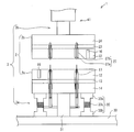
- the sticking device 1 includes a pair of plate members 2 that sandwich a laminated body (not shown) and a column member 3 that supports the plate members 2.
- the sticking device 1 can be sealed at the time of sticking, and is housed in a chamber (not shown) in which the inside of the sticking device 1 can be reduced in pressure using a suction device or the like.
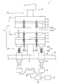
- the sticking device 1 in FIG. 1 shows a configuration in the case where the flatness at the time of pressing the mounting plate 12 to be described later is manually maintained, and the sticking device 1 in FIG. The structure in the case of maintaining is shown. In the following, common configurations will be described with the same reference numerals added.
- the support plate 14 is formed of a metal such as stainless steel, ceramics, or stone. Therefore, the intermediate plate 13 has a function as an insulator that prevents a short circuit between the heating device and the support plate 14. Further, since the support plate 14 is made of metal, it is easy to fix the lower plate member 2a to the lower support member 3a.
- the mounting plate 12, the intermediate plate 13, and the support plate 14 are fixed to each other with a plurality of bolts and nuts. Therefore, when the support plate 14 is made of metal, fixing with bolts and nuts is easy.
- the surface of the mounting plate 12 is formed so that the flatness when not pressed is 1.0 ⁇ m or less.
- the above flatness is a numerical value indicating the degree of unevenness with respect to the flat surface
- “the flatness is 1.0 ⁇ m or less” means that the surface of the mounting plate 12 (and a pressing plate 22 described later) at the time of non-pressing. It means that the unevenness is ⁇ 1.0 ⁇ m or less.
- the mounting plate 12 has a thickness (thickness in the vertical direction) of, for example, 35 mm or more so that the amount of bending at the time of pressing can be reduced. Since the mounting plate 12 is made of ceramics, it can be easily processed so that the flatness of the surface thereof is 1.0 ⁇ m or less.
- ceramic has a smaller coefficient of thermal expansion than metal, it is possible to reduce the curvature and distortion of the surface of the mounting plate 12 and the surface of the pressing plate 22 when pressed in a heated state, that is, the curvature and distortion. Therefore, the flatness (levelness) of each surface can be maintained.
- the lower plate member 2a further includes a thermometer 16 made of, for example, a thermocouple for measuring the temperature of the surface of the mounting plate 12, and facilitates a transport operation by the transport device at a portion of the mounting plate 12 that is in contact with the laminate.
- a plurality of conveying pins 17 are provided for lifting the laminated body during conveyance of the laminated body.
- the upper plate member 2b is a part in contact with the laminated body, for example, a pressing plate 22 that presses the support plate, a support plate 24 that is a part fixed to the center support member 41 of the upper support member 3b of the column member 3,
- the intermediate plate 23 is provided between the pressing plate 22 and the support plate 24.
- the pressing plate 22 and the intermediate plate 23 are made of ceramics such as alumina.
- the upper plate member 2b is heated to heat the laminate to 23 to 300 ° C. during pressing, for example, a heating device such as a surface heater or a ribbon heater (not shown) ) Is sandwiched. That is, the upper plate member 2b has a built-in heating device.
- the support plate 24 is made of a metal such as stainless steel, ceramics, or stone. Therefore, the intermediate plate 23 has a function as an insulator that prevents a short circuit between the heating device and the support plate 24. Further, since the support plate 24 is made of metal, the upper plate member 2b can be easily fixed to the upper support member 3b.
- the pressing plate 22, the intermediate plate 23, and the support plate 24 are fixed to each other with a plurality of bolts and nuts. Therefore, when the support plate 24 is made of metal, fixing with bolts and nuts is easy.
- the surface of the pressing plate 22 is formed so that the flatness when not pressed is 1.0 ⁇ m or less. Further, the pressing plate 22 has a thickness (a thickness in the vertical direction) of, for example, 35 mm or more so that the amount of bending at the time of pressing can be reduced. Since the pressing plate 22 is formed of ceramics, it can be easily processed so that the flatness of the surface thereof is 1.0 ⁇ m or less.
- the upper plate member 2b is further provided with a thermometer 16 made of, for example, a thermocouple for measuring the temperature of the surface of the pressing plate 22, and the laminated body is attached to the upper plate member 2b at a portion in contact with the laminated body in the pressing plate 22.
- a plurality of prevention members 27 for preventing sticking are provided.
- the column member 3 is arranged in the vertical direction, and includes a lower support member 3a that supports the lower plate member 2a and an upper support member 3b that supports the upper plate member 2b.
- the lower support member 3a and the upper support member 3b are formed of a metal such as stainless steel.
- the lower support member 3a is fixed to the base 30, and a center support member 31 that supports at least the central portion of the lower plate member 2a, and a plurality of lower support members 3a that are fixed to the base 30 and support other than the central portion of the lower plate member 2a.
- the lower side support member 3a is supporting the lower side plate member 2a so that the surface of the mounting plate 12 may become horizontal.
- the diameter of the center support member 31 only needs to have a strength necessary to support the lower plate member 2a at the time of pressing, but a smaller one is required so as not to release heat of the lower plate member 2a. desirable.
- the lower support member 3a is in the range of 3 to 10 in order to support the entire lower plate member 2a in a balanced manner without releasing the heat of the lower plate member 2a. It is preferable that the number is 6 or 8, more preferably.
- the plurality of peripheral support members 32 are arranged at equal intervals to support the entire lower plate member 2a in a balanced manner, that is, so that the level of the surface of the mounting plate 12 can be maintained. Yes.
- the diameter of the peripheral support member 32 only needs to have a strength necessary for reducing the amount of bending of the lower plate member 2a at the time of pressing, but in order not to let the heat of the lower plate member 2a escape. The thinner one is desirable.
- the peripheral support member 32 is composed of an upper support member 33a, a lower support member 33b, and a connecting member 33c that connects both the support members 33a and 33b.
- the peripheral support member 32 can be expanded and contracted manually using the.
- the connecting member 33c is formed of, for example, a screw member that can rotate against the pressing force of the upper plate member 2b, and the distance between the support members 33a and 33b can be increased by rotating the connecting member 33c.
- the flatness (horizontalness) of the surface of the mounting plate 12 is maintained by adjusting and correcting the curvature and distortion of the surface of the mounting plate 12.
- the peripheral support member 32 includes a cylindrical portion 32a and a support portion 32b accommodated in the cylindrical portion 32a.
- the support portion 32b can be expanded and contracted relatively in the moving direction of the upper plate member 2b, that is, in the vertical direction, by entering and exiting the cylindrical portion 32a.
- the support portion 32b is fixed to the reduction gear 36 having a high gear ratio through a hermetic seal 35 fixed to the base 30, and presses the lower plate member 2a against the pressing force by the upper plate member 2b.
- the pulse is controlled by the control unit 39 described later, and the motor controller 38 is By being driven through the reduction gear 36 by the pulse motor 37, it can be expanded and contracted in units of 0.1 ⁇ m.
- the support portion 32b is pulse-controlled by the control portion 39 even when not pressed, so that the flatness of the surface of the mounting plate 12 is 1.0 ⁇ m or less, that is, the surface of the mounting plate 12 is curved or
- the flatness (horizontalness) of the surface of the mounting plate 12 is maintained by correcting distortion and the like.
- the support portion 32b is manually controlled using a tool or the like instead of being pulse-controlled by the control portion 39 when not pressed, thereby correcting the curvature or distortion of the surface of the mounting plate 12.
- the flatness of the surface of the mounting plate 12 may be maintained.
- the configuration and method for correcting the curvature or distortion of the surface of the mounting plate 12 at the time of non-pressing are not particularly limited, and if the planarity of the surface of the mounting plate 12 can be maintained, Various configurations and methods can be employed.
- the upper support member 3b is connected to a pressure device (not shown) that applies (loads) a pressing force to press the laminated body, and includes at least a center support member 41 that supports at least the central portion of the upper plate member 2b. ing. And the upper side support member 3b is fixing the upper side plate member 2b so that the surface of the press plate 22 may become horizontal.
- the diameter of the center support member 41 only needs to have a strength necessary to support the upper plate member 2b during pressing, but a smaller one is desirable so as not to release heat of the upper plate member 2b.
- the center support member 41 is movable in the vertical direction by being driven by a pressure device. Accordingly, the upper support member 3b supports the upper plate member 2b so as to be movable in order to apply a pressing force to the stacked body.
- the upper support member 3b is configured to include only the center support member 41, but similarly to the lower support member 3a, the peripheral support member is further included. It may be. That is, the upper support member 3b may be composed of a center support member 41 and a plurality of peripheral support members that are provided on the center support member 41 and support other than the center portion of the upper plate member 2b. In this configuration, the number of the peripheral support members included in the upper support member 3b is 3 to 10 so as not to release the heat of the upper plate member 2b and to support (press) the entire upper plate member 2b in a balanced manner. It is preferable to be within the range, and it is more preferable that the number is 6 or 8.
- the plurality of peripheral supporting members are arranged at equal intervals to support (press) the entire upper plate member 2b in a balanced manner, that is, to maintain the level of the surface of the pressing plate 22. That's fine.
- the diameter of the peripheral support member only needs to have a strength necessary to reduce the amount of bending of the upper plate member 2b during pressing, but the thinner one is not to release heat of the upper plate member 2b. desirable.
- pulse control is performed at a high gear ratio by a control unit 39 which will be described later, and 0.1 ⁇ m unit is driven by the pulse motor 37 It only needs to be stretchable.
- the support portion of the upper support member 3b is pulse-controlled by the control unit 39 even when not pressed, so that the flatness of the surface of the pressing plate 22 is 1.0 ⁇ m or less. That is, the flatness (horizontalness) of the surface of the pressing plate 22 is maintained by correcting the curvature and distortion of the surface of the pressing plate 22.
- the support portion is manually expanded and contracted using, for example, a tool to correct the curvature and distortion of the surface of the pressing plate 22. It may be configured to maintain the flatness of the surface of the pressing plate 22.
- the configuration and method for correcting the curvature and distortion of the surface of the pressing plate 22 when not pressed are not particularly limited, and various types can be used as long as the flatness of the surface of the pressing plate 22 can be maintained. Configurations and methods can be employed.
- the sticking device 1 shown in FIG. 2 includes a detection unit 40 that detects (detects) the amount of bending of the plate member 2 that occurs when a pressing force is applied to the laminate, and the deflection that the detection unit 40 detects (detects). And a control unit 39 that expands and contracts the peripheral support members 32 through the motor controller 38 so that the amount is offset.
- the amount of bending of the plate member 2 that occurs when a pressing force is applied to the laminated body is detected so that the peripheral support member 32 can be manually expanded and contracted.
- a detection unit (not shown) that performs (detects) is provided.
- the detection unit 40 is, for example, a load cell (load cell) that is a sensor that detects a load applied to the peripheral support member 32 that supports the lower plate member 2a of the plate member 2 and converts the load into an electrical signal. The amount of deflection is detected using. That is, the detection unit 40 detects the load applied to each peripheral support member 32 and sets the amount of movement of the support unit 32b to the motor controller 38 via the control unit 39 so that these loads are uniform.
- the drive of the pulse motor 37 is adjusted.
- the detection unit 40 can be configured by including at least three load cells.
- the load cell may be a compression type, and any of a beam type, a column type, an S-shape, and a diaphragm type can be used.
- the control unit 39 adjusts the driving of each pulse motor 37 via the motor controller 38 by, for example, sequence control so that a predetermined pressure to be applied to the stacked body is uniformly applied over the entire mounting plate 12, and the peripheral support member 32 is expanded and contracted.
- the detection unit 40 may be configured by a sensor (displacement meter) that detects torque applied to the pulse motor 37 that extends and contracts the peripheral support member 32 instead of including a load cell.
- the control unit 39 performs, for example, sequence control so that the torque applied to the plurality of pulse motors 37 is uniform, that is, the predetermined pressure to be applied to the stacked body is uniformly applied over the entire mounting plate 12. Then, the drive of each pulse motor 37 is adjusted via the motor controller 38 so as to match the preset torque value, and the peripheral support member 32 is expanded and contracted.
- An amplifier may be provided between the motor controller 38 and the pulse motor 37 as necessary.
- the detection unit 40 is configured to measure the amount of bending of the plate member 2, that is, the mounting plate 12 and the pressing plate 22 with a laser displacement meter or the like, so that the amount of bending can be detected without contact. May be.
- the control unit 39 sets the detection value of each detection unit (a load cell, a sensor for detecting torque, a laser displacement meter, etc.) so that the detection value of the peripheral support member 32 is uniform.
- the expansion / contraction operation of the support portion 32b (and the support portion of the peripheral support member when the upper support member 3b includes a peripheral support member) is configured to perform pulse control. That is, the detection unit 40 and the control unit 39 feedback-control the amount of deflection of the peripheral portion of the mounting plate 12 and the peripheral portion of the pressing plate 22 when the laminate is pressed, that is, when the substrate and the support are attached. Therefore, the substrate and the support can be uniformly attached via the adhesive layer.
- control unit 39 extends and retracts the support portion 32b of the peripheral support member 32 (and the support portion of the peripheral support member when the upper support member 3b includes the peripheral support member) even when not pressed.
- the pulse motor 37 is configured to perform pulse control. That is, the support portion 32b always corrects the curvature or distortion of the surface of the mounting plate 12 and the surface of the pressing plate 22 regardless of the pressing operation, and the flatness (horizontal) of the surface of the mounting plate 12 and the surface of the pressing plate 22 (horizontal).
- the expansion / contraction operation is pulse-controlled by the control unit 39 so as to maintain the characteristics).
- the control unit 39 sets the movement amount of the support unit 32b in the motor controller 38 in advance and drives each pulse motor 37. Adjust. Further, when the drive of each pulse motor 37 is adjusted by the torque applied to the pulse motor 37, the control unit 39 sets a predetermined (preset) torque value in the motor controller 38 and sets each pulse motor 37. Adjust the drive.
- the control unit 39 is configured to cancel the pulse control of the expansion / contraction operation of the support portion 32b so that the support portion 32b can be manually expanded / contracted using a tool or the like when not pressed. May be.
- the prevention member 27 sticks the laminate to the pressing plate 22 when the lower plate member 2 a and the upper plate member 2 b are separated after pressing the laminate. It is a member to prevent.
- the prevention member 27 is made of a metal such as stainless steel, and includes a pin 27a having a round tip and a spring 27b that urges the pin 27a so as to protrude from the surface of the pressing plate 22.
- the urging force of the spring 27b is adjusted so that the pin 27a is pushed into the pressing plate 22 while pressing the laminated body, and the pin 27a protrudes from the surface of the pressing plate 22 when the pressing of the laminated body is released. ing.
- the pin 27a prevents sticking of the laminated body without attaching a wrinkle to the laminated body.
- the transfer pin 17 is a member that lifts the laminate when the laminate is transported in order to facilitate the transport operation by the transport device before and after the pressing operation.
- the transfer pin 17 is made of a metal such as stainless steel having a round tip, and is movably installed inside the placement plate 12.
- the said conveyance pin 17 is accommodated in the mounting plate 12 when the laminated body is pressed by the control unit 39, for example, and protrudes from the surface of the mounting plate 12 when the pressing of the laminated body is released. So that its operation is controlled.
- the conveyance pin 17 lifts the said laminated body from the mounting plate 12 surface at the time of conveyance of a laminated body, without attaching a wrinkle to a board
- the lower plate member 2a is fixed and the upper plate member 2b is driven up and down by the pressurizing device via the upper support member 3b.
- the affixing device according to the present invention may be configured such that the upper plate member 2b is fixed and the lower plate member 2a is driven in the vertical direction by the pressurizing device via the lower support member 3a, or the lower plate member 2a and the upper plate member 2b may be configured to be driven in the vertical direction.
- a substrate, an adhesive layer, and a support plate are laminated in this order in the center of the mounting plate 12 of the lower plate member 2a in the sticking device 1 accommodated in the chamber so that the substrate and the support plate do not shift.
- the laminated body temporarily fixed is transported using a transport device such as a robot arm, and placed with the substrate side facing down (transport process). At this time, the inside of the chamber is in a reduced pressure environment.
- the pair of plate members 2 is preheated to 150 to 250 ° C. by a heating device.
- the support portion 32b of the peripheral support member 32 (and the support portion of the peripheral support member when the upper support member 3b includes the peripheral support member) is the periphery of the mounting plate 12 and the periphery of the pressing plate 22.
- An appropriate expansion and contraction operation is performed so as to maintain the flatness (horizontality) of the surface of the mounting plate 12 and the surface of the pressing plate 22 by correcting the curvature and distortion of the portion.
- the pressing plate 22 is brought into contact with the support plate by lowering the upper plate member 2b in the sticking device 1, and the laminate is pressed and heated by further lowering (sticking step and heating step). That is, the substrate, the adhesive layer, and the support plate are pressed and heated in a reduced pressure environment.
- the pressing force is preferably such that a load of 4 to 6 t is applied to the entire substrate.
- the adhesive layer is preferably at least at room temperature (23 ° C.) or higher, for example, at a glass transition point (Tg) or higher due to the low-temperature tackiness (tackiness) of the thermoplastic resin that is the adhesive material of the adhesive layer. It is more preferable to heat until it reaches the temperature. By heating the adhesive layer until the temperature becomes equal to or higher than the glass transition point of the thermoplastic resin, the thermal fluidity of the adhesive layer is improved and the adhesive layer is easily deformed.
- the temperature of the contact surface is preferably in the range of 23 to 250 ° C, more preferably in the range of 150 ° C to 250 ° C. preferable.
- the heating time that is, the pressing time is preferably 2 to 4 minutes, and more preferably 2 to 3 minutes.
- the detecting unit 40 detects the amount of deflection of the plate member 2 in a non-contact manner through the pasting step and the heating step, that is, while the pasting device 1 is operating. Based on the detection result (measurement result) of the detection unit 40, the portion 39 of the support portion 32b of the peripheral support member 32 (and the support portion of the peripheral support member when the upper support member 3b includes the peripheral support member) Pulse control of expansion and contraction. That is, the mounting plate 12 or the pressing plate 22 is feedback-controlled so that the amount of deflection of the peripheral portion is 1.0 ⁇ m or less with the central portion as a reference. Therefore, the amount of bending of the plate member 2 that occurs when a pressing force is applied to the laminate can be offset.
- the sticking apparatus 1 performs the sticking process and the heating process at the same time, the sticking time for sticking the substrate and the support can be shortened as compared with the case where both processes are performed separately. Further, since the inside of the chamber is a reduced pressure environment, bubbles are not mixed between the adhesive layer, the substrate and the support plate, and can be suitably attached.
- the sticking device according to the present invention can be widely used, for example, in the manufacturing process of miniaturized semiconductor devices.
Landscapes
- Engineering & Computer Science (AREA)
- Physics & Mathematics (AREA)
- Condensed Matter Physics & Semiconductors (AREA)
- General Physics & Mathematics (AREA)
- Manufacturing & Machinery (AREA)
- Computer Hardware Design (AREA)
- Microelectronics & Electronic Packaging (AREA)
- Power Engineering (AREA)
- Fluid Mechanics (AREA)
- Container, Conveyance, Adherence, Positioning, Of Wafer (AREA)
Priority Applications (3)
| Application Number | Priority Date | Filing Date | Title |
|---|---|---|---|
| KR1020167019018A KR101678352B1 (ko) | 2012-06-20 | 2013-05-07 | 첩부 장치 |
| US14/408,903 US9548232B2 (en) | 2012-06-20 | 2013-05-07 | Attaching apparatus |
| KR1020157000444A KR20150031435A (ko) | 2012-06-20 | 2013-05-07 | 첩부 장치 |
Applications Claiming Priority (2)
| Application Number | Priority Date | Filing Date | Title |
|---|---|---|---|
| JP2012139213A JP5977592B2 (ja) | 2012-06-20 | 2012-06-20 | 貼付装置 |
| JP2012-139213 | 2012-06-20 |
Publications (1)
| Publication Number | Publication Date |
|---|---|
| WO2013190926A1 true WO2013190926A1 (ja) | 2013-12-27 |
Family
ID=49768532
Family Applications (1)
| Application Number | Title | Priority Date | Filing Date |
|---|---|---|---|
| PCT/JP2013/062816 Ceased WO2013190926A1 (ja) | 2012-06-20 | 2013-05-07 | 貼付装置 |
Country Status (5)
| Country | Link |
|---|---|
| US (1) | US9548232B2 (enExample) |
| JP (1) | JP5977592B2 (enExample) |
| KR (2) | KR101678352B1 (enExample) |
| TW (1) | TWI505939B (enExample) |
| WO (1) | WO2013190926A1 (enExample) |
Families Citing this family (3)
| Publication number | Priority date | Publication date | Assignee | Title |
|---|---|---|---|---|
| JP6855399B2 (ja) * | 2018-01-26 | 2021-04-07 | 株式会社スギノマシン | ノズルの振れの測定方法及びその装置 |
| JP7355709B2 (ja) * | 2020-05-29 | 2023-10-03 | 株式会社 日立パワーデバイス | 接合治具および半導体装置の製造方法 |
| IT202100018458A1 (it) * | 2021-07-13 | 2023-01-13 | Amx Automatrix S R L | Pressa di sinterizzazione |
Citations (5)
| Publication number | Priority date | Publication date | Assignee | Title |
|---|---|---|---|---|
| JPH07335512A (ja) * | 1994-06-08 | 1995-12-22 | Canon Inc | 接合方法および接合装置および接合物 |
| JP2002323694A (ja) * | 2001-04-24 | 2002-11-08 | Hitachi Industries Co Ltd | 基板貼り合わせ方法及び貼り合わせ装置 |
| JP4245138B2 (ja) * | 2003-03-11 | 2009-03-25 | 富士通株式会社 | 基板貼合せ装置及び基板貼合せ方法 |
| JP2009135451A (ja) * | 2007-10-23 | 2009-06-18 | Semiconductor Energy Lab Co Ltd | 半導体基板、表示パネル並びに表示装置の製造方法 |
| JP2012069900A (ja) * | 2010-08-23 | 2012-04-05 | Tokyo Electron Ltd | 接合システム、基板処理システム、接合方法、プログラム及びコンピュータ記憶媒体 |
Family Cites Families (24)
| Publication number | Priority date | Publication date | Assignee | Title |
|---|---|---|---|---|
| JP3165453B2 (ja) | 1991-01-31 | 2001-05-14 | 富士通株式会社 | プラズマディスプレイパネルの製造方法 |
| JPH09316399A (ja) * | 1996-05-28 | 1997-12-09 | Canon Inc | 基板貼合せ装置及び基板貼合せ方法 |
| JP2980073B2 (ja) * | 1997-08-29 | 1999-11-22 | 日本電気株式会社 | 熱圧着装置及びその制御方法 |
| US6081414A (en) | 1998-05-01 | 2000-06-27 | Applied Materials, Inc. | Apparatus for improved biasing and retaining of a workpiece in a workpiece processing system |
| JP2002192394A (ja) | 2000-12-28 | 2002-07-10 | Mitsubishi Gas Chem Co Inc | 無機基板のプレス加工法およびプレス装置 |
| JP2003241157A (ja) * | 2002-02-21 | 2003-08-27 | Shibaura Mechatronics Corp | 基板貼り合わせ装置、基板貼り合わせ方法、及び液晶表示パネルの製造装置、並びに製造方法 |
| JP2003347360A (ja) * | 2002-05-31 | 2003-12-05 | Sumitomo Electric Ind Ltd | ボンディングステージ |
| KR100511854B1 (ko) | 2002-06-18 | 2005-09-02 | 아네르바 가부시키가이샤 | 정전 흡착 장치 |
| JP4031732B2 (ja) * | 2003-05-26 | 2008-01-09 | 京セラ株式会社 | 静電チャック |
| JP4513329B2 (ja) * | 2004-01-16 | 2010-07-28 | 東京エレクトロン株式会社 | 処理装置 |
| US20060000802A1 (en) * | 2004-06-30 | 2006-01-05 | Ajay Kumar | Method and apparatus for photomask plasma etching |
| JP4480660B2 (ja) * | 2005-10-27 | 2010-06-16 | Necエンジニアリング株式会社 | 基板貼り合わせ装置 |
| CN101322237B (zh) * | 2006-01-31 | 2010-06-23 | 东京毅力科创株式会社 | 基板处理装置及其使用的基板载置台和暴露于等离子体的部件 |
| KR20080002323A (ko) | 2006-06-30 | 2008-01-04 | 엘지.필립스 엘시디 주식회사 | 합착 스테이지와 그 제어 장치 및 방법 |
| JP5160802B2 (ja) | 2007-03-27 | 2013-03-13 | 東京エレクトロン株式会社 | プラズマ処理装置 |
| KR100961871B1 (ko) | 2008-04-02 | 2010-06-09 | 에이피시스템 주식회사 | 기판 접합 장치 |
| JP2011530833A (ja) | 2008-08-12 | 2011-12-22 | アプライド マテリアルズ インコーポレイテッド | 静電チャックアセンブリ |
| WO2010101191A1 (ja) | 2009-03-03 | 2010-09-10 | 東京エレクトロン株式会社 | 載置台構造、成膜装置、及び、原料回収方法 |
| JP5482282B2 (ja) * | 2009-03-03 | 2014-05-07 | 東京エレクトロン株式会社 | 載置台構造及び成膜装置 |
| KR101522633B1 (ko) | 2009-04-08 | 2015-05-22 | 주식회사 원익아이피에스 | 진공처리장치 |
| FR2961630B1 (fr) | 2010-06-22 | 2013-03-29 | Soitec Silicon On Insulator Technologies | Appareil de fabrication de dispositifs semi-conducteurs |
| KR101145756B1 (ko) | 2010-07-30 | 2012-05-16 | 이지스코 주식회사 | 고무 점착식 척킹기구 및 이를 이용한 기판 합착장치 |
| JP6106162B2 (ja) * | 2011-05-31 | 2017-03-29 | アプライド マテリアルズ インコーポレイテッドApplied Materials,Incorporated | 縁部、側部及び裏面の保護を備えたドライエッチングのための装置及び方法 |
| TWI585028B (zh) * | 2013-01-30 | 2017-06-01 | 斯克林集團公司 | 剝離裝置及剝離方法 |
-
2012
- 2012-06-20 JP JP2012139213A patent/JP5977592B2/ja active Active
-
2013
- 2013-05-07 US US14/408,903 patent/US9548232B2/en active Active
- 2013-05-07 WO PCT/JP2013/062816 patent/WO2013190926A1/ja not_active Ceased
- 2013-05-07 KR KR1020167019018A patent/KR101678352B1/ko active Active
- 2013-05-07 KR KR1020157000444A patent/KR20150031435A/ko not_active Ceased
- 2013-05-15 TW TW102117203A patent/TWI505939B/zh active
Patent Citations (5)
| Publication number | Priority date | Publication date | Assignee | Title |
|---|---|---|---|---|
| JPH07335512A (ja) * | 1994-06-08 | 1995-12-22 | Canon Inc | 接合方法および接合装置および接合物 |
| JP2002323694A (ja) * | 2001-04-24 | 2002-11-08 | Hitachi Industries Co Ltd | 基板貼り合わせ方法及び貼り合わせ装置 |
| JP4245138B2 (ja) * | 2003-03-11 | 2009-03-25 | 富士通株式会社 | 基板貼合せ装置及び基板貼合せ方法 |
| JP2009135451A (ja) * | 2007-10-23 | 2009-06-18 | Semiconductor Energy Lab Co Ltd | 半導体基板、表示パネル並びに表示装置の製造方法 |
| JP2012069900A (ja) * | 2010-08-23 | 2012-04-05 | Tokyo Electron Ltd | 接合システム、基板処理システム、接合方法、プログラム及びコンピュータ記憶媒体 |
Also Published As
| Publication number | Publication date |
|---|---|
| TWI505939B (zh) | 2015-11-01 |
| TW201404598A (zh) | 2014-02-01 |
| JP5977592B2 (ja) | 2016-08-24 |
| US9548232B2 (en) | 2017-01-17 |
| US20150325463A1 (en) | 2015-11-12 |
| KR20150031435A (ko) | 2015-03-24 |
| KR20160088946A (ko) | 2016-07-26 |
| KR101678352B1 (ko) | 2016-11-21 |
| JP2014003245A (ja) | 2014-01-09 |
Similar Documents
| Publication | Publication Date | Title |
|---|---|---|
| CN103026482B (zh) | 利用临时载体处理衬底 | |
| TWI697938B (zh) | 基板貼合裝置及基板貼合方法 | |
| JP6148532B2 (ja) | 貼付装置及び貼付方法 | |
| JP5977592B2 (ja) | 貼付装置 | |
| JP2008300414A (ja) | 薄膜形成装置および薄膜形成方法 | |
| JP5639617B2 (ja) | 貼付装置および貼付方法 | |
| TW201801136A (zh) | 基板貼合裝置及基板貼合方法 | |
| KR101747485B1 (ko) | 시트 부착 장치 및 부착 방법 | |
| JP6046926B2 (ja) | 貼付装置 | |
| JP6055597B2 (ja) | 貼付方法及び貼付装置 | |
| JP6291275B2 (ja) | 貼付方法 | |
| TW201235197A (en) | Substrate assembling device | |
| JP6799988B2 (ja) | 貼付装置 | |
| JP2001126851A (ja) | 半導体ウエハーにおけるヒータ装置およびその製造方法 | |
| JP5356873B2 (ja) | 電子部品の実装装置及び実装方法 | |
| JP3348261B2 (ja) | 基板の貼り合わせ方法 |
Legal Events
| Date | Code | Title | Description |
|---|---|---|---|
| 121 | Ep: the epo has been informed by wipo that ep was designated in this application |
Ref document number: 13806137 Country of ref document: EP Kind code of ref document: A1 |
|
| WWE | Wipo information: entry into national phase |
Ref document number: 14408903 Country of ref document: US |
|
| NENP | Non-entry into the national phase |
Ref country code: DE |
|
| ENP | Entry into the national phase |
Ref document number: 20157000444 Country of ref document: KR Kind code of ref document: A |
|
| 122 | Ep: pct application non-entry in european phase |
Ref document number: 13806137 Country of ref document: EP Kind code of ref document: A1 |